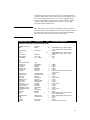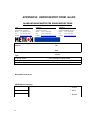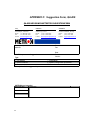
1
Q A - ID S U s e r & S e r v ic e M a n u a l Q A - ID S In f u s io n P u m p T e s t e r 1 Copyright 1998 by METRON. All rights reserved. METRON: USA_ 1345 Monroe NW, Suite 255A Grand Rapids, MI 49505 Phone: (+1) 888 863-8766 Fax: (+1) 616 454-3350 E-mail: [email protected] FRANCE 30, rue Paul Claudel 91000 Evry, France Phone: (+33) 1 6078 8899 Fax: (+33) 1 6078 6839 E-mail: [email protected] NORWAY Travbaneveien 1 N-7044 Trondheim, Norway Phone: (+47) 7382 8500 Fax: (+47) 7391 7009 E-mail: [email protected] Disclaimer METRON provides this publication as is without warranty of any kind, either express or implied, including but not limited to the implied warranties of merchantability or fitness for any particular purpose. Further, METRON reserves the right to revise this publication and to make changes from time to time to the content hereof, without obligation to METRON or its local representatives to notify any person of such revision or changes. Some jurisdictions do not allow disclaimers of expressed or implied warranties in certain transactions; therefore, this statement may not apply to you. Limited Warranty METRON warrants that the QA-IDS Infusion Pump Tester will substantially conform to published specifications and to the documentation, provided that it is used for the purpose for which it was designed. METRON will, for a period of twelve (12) months from date of purchase, replace or repair any defective analyzer, if the fault is due to a manufacturing defect. In no event will METRON or its local representatives be liable for direct, indirect, special, incidental, or consequential damages arising out of the use of or inability to use the QA-IDS Infusion Pump Tester, even if advised of the possibility of such damages. METRON or its local representatives are not responsible for any costs, loss of profits, loss of data, or claims by third parties due to use of, or inability to use the QA-IDS Infusion Pump Tester. Neither METRON nor its local representatives will accept, nor be bound by any other form of guarantee concerning the QA-IDS Infusion Pump Tester other than this guarantee. Some jurisdictions do not allow disclaimers of expressed or implied warranties in certain transactions; therefore, this statement may not apply to you. Trademarks IBM is a registered trademark, and PC/XT is a trademark of IBM Corporation. Centronix is a registered trademark of Centronix Corporation. Microsoft is a registered trademark and Windows is a trademark of Microsoft Corporation. 2 Table of Contents MANUAL REVISION RECORD............................................................................................5 1. INTRODUCTION..................................................................................................................7 1.1 QA-IDS Features .........................................................................................................................7 1.2 Specifications................................................................................................................................7 1.3 General Information......................................................................................................................8 2. INSTALLATION...................................................................................................................9 2.1 Receipt, Inspection and Return.....................................................................................................9 2.2 Setup............................................................................................................................................10 2.3 Power ..........................................................................................................................................10 2.4 PRO-Soft QA-IDS.......................................................................................................................10 3. OPERATING QA-IDS........................................................................................................13 3.1 Control Switches and Connections.............................................................................................13 3.2 Key Pad Functions.....................................................................................................................14 3.3 Menu and Function Keys............................................................................................................14 3.4 Display Menus and Messages ...................................................................................................15 3.5 Printing Test Reports.................................................................................................................20 3.6 Operator Maintenance................................................................................................................22 4. INFUSION PUMP TESTING.............................................................................................23 4.1 Introduction................................................................................................................................23 4.2 Test Preparation..........................................................................................................................23 4.3 Occlusion Pressure/ Bolus Volume Testing ..............................................................................25 4.4 Infusion Flow Rate and Volume Testing....................................................................................26 5. CONTROL AND CALIBRATION....................................................................................29 5.1 Required Test Equipment...........................................................................................................29 5.2 Adjusting the Display Contrast ..................................................................................................29 5.3 Testing Power Supply to IDS.....................................................................................................29 5.4 Testing Pressure Gauge Accuracy..............................................................................................30 5.5 Testing Flow Rate Accuracy.....................................................................................................30 5.6 Checking the Battery Backup.....................................................................................................31 6. COMPONENT FUNCTIONS AND PARTS....................................................................33 6.1 Theory of Operation....................................................................................................................33 6.2 Power Supply..............................................................................................................................33 6.3 Printer Output..............................................................................................................................33 6.4 Serial Port...................................................................................................................................34 6.5 Microprocessor............................................................................................................................34 6.6 Pressure Gauge............................................................................................................................34 6.7 Pump............................................................................................................................................34 6.8 Stepper Motor/Drivers................................................................................................................34 6.9 Control Panel...............................................................................................................................35 6.10 Component Parts......................................................................................................................35 3 APPENDIX A: DIAGRAMS......................................................................................39 Processor board Component Location...........................................................................................41 6.10.1 Processor board Schematic Diagram 1 ...............................................................................42 6.10.2 Processor board Schematic Diagram 2 (Digital Part) .......................................................43 6.10.3 Processor board Schematic Diagram 3 (CPU) ..................................................................44 6.10.4 Processor board Schematic Diagram 4 (Memory) ............................................................45 6.10.5 Processor board Schematic Diagram 5 (RS232C and Printer) .........................................46 6.10.6 Processor board Schematic Diagram 6 (Digital Outputs) .................................................47 6.10.7 Processor board Schematic Diagram 7 (Digital Inputs) ....................................................48 6.10.8 Processor board Schematic Diagram 8 (A/D) ...................................................................49 6.10.9 Processor board Schematic Diagram 9 (Stepper Motor and Drivers) ..............................50 6.10.10 Processor board Schematic Diagram 10 (Pressure Sensor and Temperature) ................51 6.10.11 Processor board Schematic Diagram 11 (Main Part) ......................................................58 6.10.12 Processor board Schematic Diagram 12 (Keyboard, Pressure Sensor and Pump Index) ..........................................................................................................................................................59 APPENDIX B: ERROR REPORT FORM, QA-IDS.........................................................62 APPENDIX C: SUGGESTION FORM, QA-IDS...............................................................65 4 Manual Revision Record This record page is for recording revisions to your QA-IDS User and Service Manual that have been published by METRON or its authorized representatives. We recommend that only the management or facility representative authorized to process changes and revisions to publications: • make the pen changes or insert the revised pages; • ensure that obsolete pages are withdrawn and either disposed of immediately, or marked as superseded and placed in a superseded document file, and; • enter the information below reflecting that the revisions have been entered. Rev No Date Entered Reason 0 - Initial Release Signature of Person Entering Change 5 This page intentionally left blank. 6 1. Introduction This chapter describes the Metron’s QA-IDS Infusion Pump Tester’s features and specifications. 1.1 QA-IDS Features METRON’s QA-IDS Infusion Pump Tester is a precision instrument, designed for use by trained service technicians, for testing all types of infusion pumps according to International Electrotechnical Commission (IEC) Draft Standard 62.D (IEC 601.2.24). Tests include: • volumetric tests • bolus tests • occlusion alarm tests QA-IDS is capable of detecting a minimum volume variation of one microliter in a range of 0.10 milliliter per hour (ml/hr) to 1000.0 ml/hr. Flow measurements are taken every 30 seconds, so that the measurements are independent of the infusion pump’s flow rate. Test results, shown in the QA-IDS's LCD display, can be printed out directly, or transferred to a PC via the PRO-Soft QA-IDS test automation software. PRO-Soft lets you design test protocols, remotely control the QA-IDS, and store the test results. 1.2 Specifications 1. Flow Rate Flow Range Min. volume detection Display resolution 2. Time Interval to Achieve ± % Accuracy of Reading 1000 ml/hr 0.5% 0.6 sec 1.0% 0.3 sec 1.5% 0.2 sec 3. 100 ml/hr 0.5% 6 sec 1.0% 3 sec 1.5% 2 sec 10 ml/hr 0.5% 52 sec 1.0% 26 sec 1.5% 18 sec Pressure Generation Range: Accuracy: - 200 to + 200 mmHg: + 201 to + 600 mmHg: 4. 0.10 ml/hr - 1000.0 ml/hr 0.72 µl 0.01 ml/hr - 200 to + 600 mmHg ± 10 mmHg ± 20 mmHg Occlusion Alarm Test Measurement Range: - 400 to +1500 mmHg. 7 Accuracy: - 400 to + 500 mmHg: + 501 to + 1500 mmHg: Maximum Input Pressure: 5. ± 10 mmHg ± 2% of reading 2500 mmHg Bolus Test Accuracy: ± 20 µl 1.3 General Information Temperature Requirements +15°C to +35°C when operating 0°C to +50°C in storage Display Type Alphanumeric format Display control LCD graphic display 4 lines, 40 characters 7 function keys and a keypad Data Input/ Output (2) Parallel printer port (1); Bi-directional RS -232C (1) for Computer control Power From 110 VAC to 240 VAC, 47 / 63 Hz. Mechanical Specifications Housing Metal case Height 13.5 cm / 5.31 in. Width 23.5 cm / 9.25 in. Depth 24.5 cm / 9.65 in. Weight 4.30 kg / 9.48 lbs. Printer Port Centronics Interface Standard Accessories User and Service Manual QA-IDS (P/N 15035) Additional Accessories Carrying case Carrying case, ext. printer PRO-Soft QA-IDS software PRO-Soft QA-IDS DEMO User Manual PRO-Soft QA-IDS (P/N (P/N (P/N (P/N (P/N 15100) 10500) 15200) 15201) 15205) Storage Store in the carrying case in dry surroundings within the temperature range specified. There are no other storage requirements. Periodic Inspection The unit should be calibrated every 12 months. 8 2. Installation This chapter explains unpacking, receipt inspection and claims, and the general procedures for QA-IDS setup. 2.1 Receipt, Inspection and Return 1. Inspect the outer box for damage. 2. Carefully unpack all items from the box and check to see that you have the following items: • QA-IDS Infusion Pump Tester (P/N 15000) • User and Service Manual QA-IDS (P/N 15035) 3. If you note physical damage, or if the unit fails to function according to specification, inform the supplier immediately. When METRON AS or the company’s representative, is informed, measures will be taken to either repair the unit or dispatch a replacement. The customer will not have to wait for a claim to be investigated by the supplier. The customer should place a new purchase order to ensure delivery. 4. When returning an instrument to METRON AS, or the company representative, fill out the address label, describe what is wrong with the instrument, and provide the model and serial numbers. If possible, use the original packaging material for return shipping. Otherwise, repack the unit using : • a reinforced cardboard box, strong enough to carry the weight of the unit. • at least 5 cm of shock-absorbing material around the unit. • nonabrasive dust-free material for the other parts. Repack the unit in a manner to ensure that it cannot shift in the box during shipment. METRON’s product warranty is on page ii of this manual. The warranty does not cover freight charges. C.O.D. will not be accepted without authorization from METRON A.S or its representative. 9 2.2 Setup 1. Equipment connection is as shown in the typical setup below. 2. If PRO-Soft QA-IDS is being used, attach an RS-232 (null modem/data transfer configured) cable to the 9-pin D-sub outlet port located at the rear of the QA-IDS. Do not attach the printer cable to the QA-IDS. See below. However, if you are not using PRO-Soft QA-IDS, and are sending directly to a printer for printouts, attach the printer cable to the 25-pin outlet port . NOTE Some RS-232C cables are missing the connection between the seventh and the eighth wires in the cable. The cable may still be called NULL-modem, but it will not work with the QA-IDS. Refer to the PRO-Soft QA-IDS Users Manual for more information. 2.3 Power Main On/Off Switch. QA-IDS should remain off for at least 5 seconds before switching on again, in order to allow the test circuits to discharge fully. 2.4 PRO-Soft QA-IDS PRO-Soft QA-IDS is a front-end test automation and presentation tool for METRON's QA-IDS Infusion Pump Tester. It allows you to conduct the same tests, but by remote control via an IBM-compatilbe PC/XT with MS Windows (Version 3.1 or later). 10 Each of the QA-IDS tests can be run independently from PRO-Soft in the “Manual” test mode. Results are shown on the PC screen during testing, and the user is prompted to set the tested equipment accordingly. At the conclusion of tests, the user may print a report, store the test and results on disk, or both. Combinations of tests can be created and stored as “Test Sequences.” The program maintains a library of these sequences. In this way you can store and retrieve sequences that are appropriate for each infusion device being tested at your facility. NOTE PRO-Soft QA-IDS has its own user manual which contains all the information concerning the program. If you order a demonstration version of the program you also receive the manual. Sequences can then be used independently, or can be attached to a checklist, written procedure, and equipment data in the form of a test “Protocol.” The equipment data can be entered manually into the protocol, or it may be retrieved by PRO-Soft from the QA-MAP program or other equipment files. Protocols can be created easily for each infusion pump in your inventory, and stored for use. Test protocols with results can be printed, or stored on disk, and the results of testing can be sent back to the equipment database to close a work order and update the service history. 11 This page intentionally left blank. 12 3. Operating QA-IDS This chapter explains the operating controls, switches and menus of the QA-IDS, details how to use them in testing, and provides instructions for printing reports, and operator maintenance. 3.1 Control Switches and Connections Front Panel 1. Key Pad 11 alphanumeric keys, used to enter information. 2. Function Keys F1-F4 are used to select the functions shown in the menu bar at the bottom of the display, i.e., for selecting the function that is directly above the key. F5-F7 are used to select the function, or enter information in the message field in the same line. 3 LCD Display Shows messages, test results and function menus. 4 Inlet Inlet connection for infusion set. 5. Drain Connection for drainage tube. 6. Upgrade Keys Special function keys for firmware upgrade. 13 Rear Panel 3.2 tions 7. Power Switch Turns power ON and OFF. 8. Mains QA-IDS Mains connection for test instrument. 9. Printer Outlet Port 25 pin D-sub. Centronic output. 10. RS-232 Serial Port 9-pin D-sub Key Pad FuncThe alphanumeric keys comprise both numbers and letters. Hold the key in and it moves automatically from character to character. 3.3 Menu and Function Keys The QA-IDS uses displays, function keys and a keypad to provide flexibility and control over operations. The top three lines in the display are used for messages, status and results. The menu bar is shown at the bottom of the display. Function keys are numbered from F1 to F7. A function/menu is selected by pressing that key which is directly below/to the right of the menu unit shown in the display. 14 3.4 Display Menus and Messages 1. Startup Screen. The following screens will be displayed in sequence for the first two seconds after the QA-90 has been switched ON. 2. Main Menu This window offers the following functions: 4. • Press Occlusion Test (F5) to go to the Occlusion Test Setup Screen. See paragraph 3.4.5 below. • Press Flow Measurement (F6) to go to the Flow Measurement Test Setup Screen. See paragraph 3.4.6 below. • Press Equipment Code (F7) to record the code or name of the device under test. Press Enter (↵ ) to store. 3. PRIME (F1). When PRIME (F1) is pressed, the following display will appear: • Press GO BACK (F2) to return to the main menu. SETUP (F3) This function is used for entering general information in connection with the test. Three main displays are shown below. • Press Operator (F6) to record the operator’s name or initials. 15 5. • Press Establishment (F5) to record the establishment. • Press MAIN MENU (F4) to return to the main menu. • Press MORE (F1) and the following display will appear: • Press Serial no (F7) to record the serial number of the QAIDS being used. • Press Reference Unit (F6) to select the reference unit, as follows: mmHg mBar kg/cm2 inH2O cmH2O kPa inHg PSI • Press Alarm After Test (F5) and select Yes or No. • Press GO BACK (F2) to return to the previous display. • Press MAIN MENU (F4) to return to the main menu. • Press MORE (F1) and the following display will appear: • Press Language (F7) to select the language used for the testing. • Press Date (F6) to set the day/month/year. • Press Time (F5) to set the hour/minute/second. • Press GO BACK (F2) to return to the previous display. • Press MAIN MENU (F4) to return to the main menu. Occlusion Test (F5) The Occlusion Alarm Test is used to protect the patient. An Occlusion Pressure Alarm will be activated if the pressure inside the administration set extends preset levels. The three main test displays are shown below. 16 • Press Flow Set (F7) to set the preset value of the infusion pump. • Press Alarm Prsr (F6) to set the preset pump value. • Press START (F2) to start the Occlusion Test, and the following display will appear: The following parameters are displayed: 6. Prsr: The pressure in the connction tube. Measurement results display: max. value > instantaneous measured value > mean value in mmHg. Time: The time from test start until alarm activation. Measurement results display: max. time > elapsed time > mean time in minutes/seconds. Bolus: The volume expansion within the tube when the infusion pump alarm activates. Measurement results display: max. bolus > last executed calculation after STOP is pressed > mean bolus in milliliters. • Press GO BACK (F4) to return to the previous menu. • Press STOP (F2) to stop the test. • Press START (F2) to return to the previous menu. • Press GO BACK (F4) to return to the previous display. Flow Measurement (F6) This function is used for entering flow information in connection with the test. There are four main displays, shown below: 17 The following parameters are displayed: Flow Set: This value is the preset value of the infusion pump. All error calculations of the flow measurement are related to this value. If the Flow Set value is not entered correctly, this may cause a poor presentation with incorrect overall errors. Press Set: This function enables you to enter + (positive) or - (negative) backpressure into the system. Operation range is from -200 to +600 mmHg. dT: Interrogation time, or time between two measurements. Average value during the test interval is displayed. Recommended dT from IEC is 30 sec, and this is the minimum value to be selected on the QA-IDS. Maximum dT is 600 sec. or 10 minutes. Default value is 30 sec. • Press Flow Set (F7) to set the preset value of the infusion pump. • Press Press Set (F6) to set the relevant + or - backpressure into the system. • Press dT (F5) to set the interrogation time, or time between two measurements. • Press PR HDR (F3) to print a header. • Press MAIN MENU (F4) to return to the Main Menu. • Press MORE (F1) and the following screen will appear: The following parameters are displayed: 18 Test Time: This is the preset time for a test. Maximum testing time is 24 hours. Default value is 1 hour. Delay Time: This is the delay before the first measuring. • Press Test Time (F7) to set the actual time of the test. • Press Delay Time (F6) to set the delay before the first measurement. • Press MORE (F5) to return to the previous display. • Press PR HDR (F3) to print a header. • Press MAIN MENU (F4) to return to the Main Menu. • Press START (F2) to start flow measurement, and the Flow Measurement 1 display will appear: The following parameters are displayed: Mean Flow: The flow of the liquid volume in infusion pump every second displayed in ml/h and %. Cum. Volume: The cumulative volume from start of the test. Time Left: The remaining time before the test is finish. • Press STOP (F2) to return to the Flow measurement setup. • Press MORE (F1) and the Flow Measurement 2 display will appear. The following parameters are displayed: Inst. Flow: Instantaneous Flow shows: max. value > mean value > minimum value in %. Inst. Flow: Instantaneous Flow shows: max. value > mean value > minimum value in ml/h. Prsr: The pressure in the connection tube. • Press STOP (F2) to return to the previous display. • Press MORE (F1) to return to the Flow Measurement Setup. 19 3.5 ports Printing Test ReHard copy printouts of test results can be made if a printer is connected to the QA-IDS. See paragraph 2.2 for connecting the printer. To obtain a printout of the test, select PR HDR (F3) at the completion of the test. As can be seen by the following examples, the printouts contain: • QA-IDS unit, operator and establishment identification. • Tested equipment identification • Test setup data, and detailed reselts. • Test summary • Comments 1. Example Printout of a Flow Measurement Test. METRON QA-IDS Infusion pump tester 1.17 Operator : Equipment Code Serial no. Status Group Manufacturer : Type Model Location Flow set Press Set dT : : : Ver. Serial no.: Establishment : - - EQUIPMENT INFORMATION - : ___________________________________________ : ___________________________________________ : ___________________________________________ : ___________________________________________ ___________________________________________ : : : ___________________________________________ ___________________________________________ ___________________________________________ - - SETUP DATA FLOW MEASUREMENT TEST - ml/h Test Time : s mmHg Delay Time : s s dT Pressure Cum. Volume Inst. Flow Mean Flow No. (mmHg) (ml) (ml/h) (%) (ml/h) (%) ***************************************************************** ********* -Mean Flow : Max. Peak Flow Min. Peak Flow Cum. Volume Measurement Time Comments TEST SUMMARY - ml/h : ml/h : ml/h : ml : s : ___________________________________________ ___________________________________________ Date-Time/Signature ______________________________ 20 2. Example Printout of an Occlusion Test. METRON QA-IDS Infusion pump tester 1.17 Operator : Equipment Code Serial no. Status Group Manufacturer : Type Model Location Ver. Serial no.: Establishment : - - EQUIPMENT INFORMATION - : ___________________________________________ : ___________________________________________ : ___________________________________________ : ___________________________________________ ___________________________________________ : : : ___________________________________________ ___________________________________________ ___________________________________________ Flow set Alarm pressure - - SETUP DATA OCCLUSION TEST - : ml/h Pump type : mmHg Occlusion Test no. Alarm time (mm:ss) Bolus (ml) : Alarm pressure (mmHg) Stop pressure (mmHg) ***************************************************************** ********* - - TEST SUMMARY - No. of occlusion Mean alarm time : tests : Mean bolus : ml Mean alarm pressure : mmHg Mean stop pressure : Comments : ___________________________________________ ___________________________________________ Date-Time/Signature ______________________________ The tested equipment and comments portions enable the operator to manually enter appropriate remarks. 3. Presentation of Measuring Data Instant Flow: Flow rate measured during the last interrogation. Maximum Flow: Max. flow detected during one interrogation period. Minimum Flow: Min. flow detected during one interrogation period. Mean flow: Mean flow from start of test till elapsed time. Cumulative Volume: Accumulated or delivered volume during the test. Measured Pressure: Measured pressure in the flowline. Elapsed Time: Elapsed time from start of test. Time Left: Time left of a preprogrammed test sequence. Delay Time: Delay for calculation of measuring values for a test. 4. Scaling Conversion from mmHg to Selected Pressure Unit mmHg = 1 kg/cm2 = 0.0013 21 cmH20 mBar kPa 3.6 nance = 1.3 = 0.013 = 0.13 inHg inH2O PSI = 0.03937 = 0.5118 = 0.01885 Operator Mainte1. Draining the QA-IDS. To ensure proper functioning, and reduce the chance of malfunction, the QA-IDS should be drained: • Daily after use. • Prior to storage. • Prior to being transported. To drain the QA-IDS: • Disconnect the infusion set from the Inlet. • Press DRAIN (F2) in the Main Menu. The following display will appear: • Drain the unit until the liquid in the drain tube disappears. • Press GO BACK (F2) to return to the main menu. 2. Cleaning. The QA-IDS should be cleaned every six months, in accordance with the following procedure: • Use any of the following cleaning materials: - Sodium hypochloride, 4% solution in distilled water. - Acetic Acid, 4% solution in distilled water. - Bicarbonate of Soda, 4% solution in distilled water. 22 • Mix the cleaning fluid in distilled water. • Prime the QA-IDS with the mixture (See paragraph 3.4.3). • Allow the mixture to remain in the system for 30 minutes. • Drain the unit, as above • Repeat this procedure two to three times. • Set the QA-IDS on a one-hour flow test, with a flow rate of 100 ml/hr, using distilled water. 4. Infusion Pump Testing This chapter details procedures for conducting each of the QA-IDS tests. 4.1 Introduction Infusion pump testers calculate flow rates from a measured time period to fill a defined volume. If it takes one hour to fill a defined volume of 10 milliliters, the flow rate is calculated to be 10 ml/hr. This flow rate is called the instant flow rate. The minimum volume detection of this measurement is 10 milliliters, since it needs that amount to calculate a flow rate. The next instant flow rate calculation may be done when an additional volume of 10 ml is delivered to the measuring device. When two or more instant flow rates have been obtained, the calculation of a mean flow rate can be done by averaging the instant flow rates. Detecting unexpected flow changes requires detection of tiny infusion volumes, as flow measurements may only be calculated every time the defined volume is filled up. The ability to detect small infusion volume requires that measurements be made frequently, hence a high flow-sampling rate. The ability to detect only larger infusion volumes decreases the sampling rate, as well as the ability to accurately detect flow changes. International standards prescribe flow sampling to be done every thirty seconds for all flow rates to ensure a steady rate of infusion from all types of infusion devices. To fulfill this requirement, minimum volume detection of the measuring device is critical. Example: To test an infusion pump for unexpected flow changes at a flow rate of 10 ml/hr, with an accuracy of ± 2%, the following minimum flow detection is needed: Expected flow: 10 ml/hr = 166.7 pl pr. minute (divide by 60) = 83.3 µl pr. 30 sec. (divide by 2). 2% of expected flow: 83.3 µl pr. 30 sec. x 2% = 1.67 µl pr. 30 sec. A volume detection of 1.67 µl is required to detect a 2% unexpected, sudden flow change from an expected flow rate of 10 ml/hr within 30 seconds. The minimum volume detection of QA-IDS is 0.72 µl. That means that less than 1 µl is needed for QA-IDS to detect any sudden flow change between 0.10 ml/hr and 1000.0 ml/hr. QA-IDS performs flow-samplings every second for all flow rates. 4.2 Test Preparation 23 WAR NI NG Do not start measuring with the QA-IDS without having liquid in the system, as it may be exposed to wear. IMPOR TA NT 24 1. METRON recommends sterile, distilled water in test use, as tap water may contain too much oxygen, and potentially destructive deposits. 1. Remove all air inside the administration set before connecting it to the QA-IDS. Air passing through the measurering system will give incorrect readings. 1. Set up the test components. See below. • Connect the infusion pump being tested to the QA-IDS Inlet Port and to an infusion container. • Switch the QA-IDS ON. The following will be displayed in the LCD display for about two seconds: • Fill the administration set with liquid (Metron recommends distilled water). 2. Prime the QA-IDS. Before starting the measurements, the internal volume of the QA-IDS has to be filled with liquid . • Connect the administration set to the inlet of the QA-IDS. • Press PRIME (F1) in the Main menu and the following display will appear. CAUTION Prime the unit properly. • Start the infusion pump with a high flow rate. Keep the QA-IDS working until there is no more air in the tubes. Timeout is max. 10 minutes. • Press GO BACK (F1) to return to the main menu. 4.3 Occlusion Pressure/ Bolus Volume Testing To protect the patient, an infusion device should include an occlusion pressure alarm. This alarm should activate if the pressure inside the administration set exceeds preset levels. Since an occlusion with built up pressure also distends the administration line, an excess volume of liquid is stored in the line. This is the Bolus volume, which is a discrete quantity of liquid delivered in a short time, and is not intended to form a part of the continuous flow output. Such uncontrolled volume may also be a risk to the patient, and must be measured for the infusion pump. 1. Prime the QA-IDS as per paragraph 4.2.2 above. 2. Press Occlusion Test (F5) in the Main Menu and the following display will appear: 3. Press Flow Set (F7) to select an intermediate flow rate on the infusion device. 4. Press Alarm Prsr (F6) to enter a preset pump value on pumps having programmable occlusion alarm settings. 5. Press Pump Type (F5) and select between the two options: Standard or Reversing. 6. Start the infusion, and simultaneously press START (F2) to start the Occlusion Test, and the following display will appear. During the test, the pressure (Prsr) in the administration set and elapsed time will be displayed. When the Occlusion Alarm on the infusion pump is activated, press STOP (F2) to stop the test, and the following display will appear. 25 The following parameters will then be displayed: Prsr: The pressure in the connction tube. Measurement results display: max. value > instantaneous measured value > mean value in mmHg. Note: For multiple measurements, max. measured value > last measured value > mean value are displayed. Time: The time from test start until alarm activation. Measurement results display: max. time > elapsed time > mean time in minutes/seconds. Bolus: The volume expansion within the tube when the infusion pump alarm activates. Measurement results display: max. bolus > last executed calculation after STOP is pressed > mean bolus in milliliters. Note: Maximum bolus volume to be measured with a standard QA-IDS is about 1.7 milliliters. 7. A new measurement in a series is initiated by just pressing START (F2) to start test. According to the IEC an occlusion test should be run with different settings of flow rate and, if the pump has a programmable occlusion pressure alarm, different alarm settings are recommended. 4.4 Infusion Flow Rate and Volume Testing 1. Press Flow measurement (F6) in from the Main Menu and the display will show the Flow Measurement Setup 1 Menu. The following parameters are displayed: 26 Flow Set: This value is the preset value of the infusion pump. All error calculations of the flow measurement are related to this value. If the Flow Set value is not entered correctly, this may cause a poor presentation with incorrect overall errors. Press Set: This function gives the possibility to enter + (positive) or - (negative) backpressure into the system. Operation range is from -200 to +600 mmHg. dT: Interrogation time, or time between two measurements. Average value during the test interval is displayed. Recommended dT from IEC is 30 sec, and this is the minimum value to be selected on the QA-IDS. Maximum dT is 600 sec. or 10 minutes. Default value is 30 sec. • Press Flow Set (F7) and enter the preset value of the infusion pump being tested. • Press Press Set (F6) and enter in the relevant + or - backpressure. • Press dT (F5) if values other than the default 30 seconds is desired, and enter the new value. 2. Press MORE (F1) in Flow Measurement Setup 1, and the display will show the Flow Measurement Setup 2. The following parameters will then be displayed: Test Time: This is the preset time for a test. Maximum testing time is 24 hours. Default value is 1 hour. Delay Time: This is the delay before the first measuring. • Press Test Time (F7) to select a time for the test other than the default time of 1 hour. • Press Delay Time (F6) to set a delay before the first measurement, if desired. • Press MORE (F1) to return to the Flow Measurement Setup 1 Menu. 3. Press START (F2) to start flow measurement in either the Flow Measurement Setup 1 or Flow Measurement Setup 2, and the following display will appear: The following parameters will then be displayed: Mean Flow: The flow of the liquid volume in infusion pump every second, displayed in milliliters per hour (ml/h) and percent (%). Cum. Volume: The cumulative volume from start of the test. Time Left: The remaining time before completion of the test. • Press STOP (F2) to return to the Flow Measurement 1 display. 27 • Press MORE (F1) and the Flow Measurement 2 display will appear. The following parameters will then be displayed: Inst. Flow: Instantaneous Flow shows: max. value > mean value and minimum value in percent (%). Inst. Flow: Instantaneous Flow shows: max. value > mean value and minimum value in milliliters per hour (ml/h). Prsr: Shows pressure in the connection tube. • Press STOP (F2) to return to the previous display. • Press MORE (F1) to return to the Flow Measurement Setup. 28 5. Control and Calibration This chapter explains the QA-IDS maintenance procedures, including testing and calibration. 5.1 Required Test Equipment • Digital multimeter, 10 µV resolution, 0.1% accuracy. • Pressure/vacuum generator, - 400 to + 1700 mmHg pressure. • Pressure gauge. • Calibrated infusion pump. 5.2 Adjusting the Display Contrast WARNING! HIGH VOLTAGES ARE CAPABLE OF CAUSING DEATH! USE EXTREME CAUTION WHEN PERFORMING TESTS AND CALIBRATION. USE ONLY INSULATED TOOLS WHEN THE UNIT IS PLUGGED IN, AND THE METAL CASE HOUSING IS OFF. 1. Remove metal case housing. 1. Set contrast in the display by adjusting potentiometer R160 (located at left of CPU) to desired contrast. See Component Location Diagram, page A-2. 5.3 Testing Power Supply to IDS 1. Disconnect cable to the stepper motor, and connect a power supply with 24 VDC and current limit set to 400 mA. 2. Measure current drawn from the supply voltage, max. 350 mA. 3. Connect mains unit and adjust the voltage to 24V. 4. Switch ON the mains voltage and measure/adjust the following voltages in the sequence given using the multimeter. There must be 0 mmHg pressure applied to the QA-IDS: Test point Level V24P (J140/1) 24 VDC ±1V Vcc (C1N12/I) + 5 VDC ± 50 mV V5N (C1N31/2) Max. deviation - 5 VDC ± 200 mV Uref 4.096 VDC ± 1 mV Uad 5 VDC ± 2 mV 29 5.4 Testing Pressure Gauge Accuracy 1. Connect pressure generator and pressure gauge to the Inlet and start calibration of the pressure gauge. 2. Set pressure to 0 mmHg and press F3. 3. Set pressure to 1000 mmHg and press F4. The pressure gauge is now calibrated. 4. Check that the QA-IDS is within specifications at - 400 and + 1700 mmHg pressure. Value - 400 mmHg Max. deviation ± 10 mmHg + 700 mmHg ± 10 mmHg + 900 mmHg ± 20 mmHg + 1700 mmHg ± 34 mmHg 5. To remove as much air pressure as possible from the pressure sensor: • Connect an infusion set with a supply of sterile, distilled water to the QA-IDS inlet. (Infusion pump or gravity-fed system can be used.) • Open the infusion set, or set the infusion pump to a rate of 250 ml/hr. • Select PRIME (F1) from the main menu to fill the hose QA-IDS measuring system with water. • Once filled, stop the infusion, and set the QA-IDS backpressure to - 400 mmHg. The tester will pump to create this negative pressure in the test circuit. • Select DRAIN (F2) and allow pump to run until it stops. • Then, set the back-pressure to 10 mmHg, and open the infusion set, pumping any remaining air out of the QA-IDS pressure sensor. 5.5 Testing Flow Rate Accuracy 1. Set QA-IDS to do a Flow Measurement, with a set flow rate (Flow Set) of 100 ml/hr, a back pressure setting (Press Set) of 0 mmHg, and a sampling interval (dT) of 30 seconds. 1. Connect infusion set of a calibrated infusion pump to the QAIDS inlet. Note: Metron recommends the use of sterile water for calibration tests. 2. Prime the QA-IDS: 30 • Turn infusion pump ON, and set flow rate at 250 ml/hr. • Select PRIME (F1) from the QA-IDS menu. • Select GO BACK (F1) when all air is cleared from the drain line. 3. Set infusion pump to 100 ml/hr. 4. Press START from the QA-IDS Flow Measurement menu. 5. Run test at each of the below settings for at least 15 minutes and check that deviations are within tolerance limits. Flow Rate - 1 ml/Hr + 10 ml/Hr Max. deviation ± 0.05 ml/Hr ± 0.5 ml/Hr Volume - 1 ml + 10 ml Max. deviation ± 0.05 ml ± 0.5 ml + 100 ml/Hr ± 5 ml/Hr + 100 ml ± 5 ml + 1000 ml/Hr ± 50 ml/Hr + 1000 ml ± 50 ml 5.6 Checking the Battery Backup 1. In the SETUP menu, check the clock for date and time. Correct if necessary. 2. Turn the QA-IDS OFF, then ON again, and verify that the correct date and time are displayed. 31 This page intentionally left blank. 32 6. Component Functions and Parts This chapter provides a description of the functions of the QA-IDS components, and a parts list for cross reference. The QA-IDS consists of an independent primary switched power supply, a keypad board, a processor board, a LCD display and an index transmitter mounted on the pump. The processor board, keypad board and index transmitter are described in diagrams, contained in Appendix A. One is a Component Location Diagram. Another, F190.20.2000.10, is a schematic diagram describing the keyboard, pressure sensor, and pump index. F190.20.1N00.10 diagrams the Processor Board Main Part. Set F190.20. 1000.10 through F190.20.1900.10 are schematic diagrams describing the processor board by function. The boards are connected by 2 x 16-conductor flat cables, 1 x 3-conductor and 1 x 2-conductor. 6.1 Theory of Operation The QA-IDS is an infusion pump tester that runs on 110 - 230 V AC mains voltage. The unit is based on a Motorola microprocessor. Controls on the front panel of the unit allow testing of all the functions of an infusion pump. QA-IDS performs tests according to IEC Draft Standard 62.D and IEC 601.2.24. Test results, which are shown in the QA-IDS LCD display, may be printed out on an external printer. A serial port (RS-232C) enables the unit to be controlled from a PC, simply by using the PRO-Soft QA-IDS software program. The program in QA-IDS is stored in RAM with battery backup, and can be updated from a PC via the built-in serial port. 6.2 Power Supply The power supply consists of a primary switched unit, mounted on the backplane, that supplies 24 VDC, 2A to the processor board (V24P). The processor board is equipped with a secondary switched regulator that generates + 5 VDC (Vcc). Via a passive filter, this is used as the supply voltage to the measurement amplifier and A/D converter (V5P). A capacitive switched supply generates - 5 VDC to the measurement amplifier and A/D converter (V5N). A reference voltage of 4.096 V is generated from V5P, which is used for the A/D and pressure sensor. The supply voltages are monitored by a watchdog, and the unit is reset if V24P falls below 20 V. The contrast on the display is regulated using R160. The stepper motor drivers are supplied directly from V24P. 6.3 Printer Output The QA-IDS has a printer output with a standard 25-pin D-sub contact for Centronics interface. The drivers are built up with TTL in- 33 verters, which are run from a register connected to the data bus. The inputs are protected against overvoltage. 6.4 Serial Port The serial port has a 9-pin D-sub male (DTE), and is connected to a PC with a null modem cable. The handshake is carried out in the software. The control signals RTS, CTS and DTR are connected on the D-sub contact. 6.5 Microprocessor The microprocessor unit consists of a Motorola processor with a clock frequency of 16 MHz, RAM, A/D converter, watchdog, real-time clock, parallel and serial I/O. The program is stored in a 128K RAM with battery backup. The setup parameters and calibration data are stored in EEPROM in the CPU. The LCD display and keypad are connected to the processor's bus via registers. The built-in A/D converter in the CPU is used to monitor the temperature and battery voltage. 6.6 Pressure Gauge The pressure gauge consists of a differential pressure sensor, a measurement amplifier, the reference voltage and an instrumentation amplifier. The pressure sensor, U1B00, is made up of a piezo-resistive element encapsulated in silicon. It is temperature- and offset-compensated. It receives its voltage supply from the reference voltage. The output signal is amplified with an instrumentation amplifier, U1B10, which is a 4 x operational amplifier. The amplified signal is proportional to the pressure measured, and is fed to a 12-bit A/D converter, U1700. To measure negative pressure, an offset of 800 mV is inserted at zero pressure. The offset is adjusted with R1 B1B. The amplification is adjusted with R1B10 to 4050 mV at 1700 mmHg. The reference voltage is generated from V5P using a variable voltage divider, R1B26, and an operational amplifier, U1B20. U1B20 is also used for temperature measurement, 6.7 Pump The QA-IDS has a pump from Saphierwerk, driven by a stepper motor. The pump is a rotating piston pump with the pump head and piston in artificial sapphire. It pumps 50 µl per revolution. The pump has a circuit board with a Hall sensor to provide an index per revolution. The index is used to measure the volume pumped. The stepper motor is a bipolar type with 200 steps per revolution. 6.8 Stepper Motor/Drivers The stepper motors are run by three circuits from Ericsson. The stepper motor driver U 1810 is connected to the CPU, and generates the control signal to two driver circuits. The stepper motor can run in full-and half-step mode. The driver circuits, U1820 and U 1830, have built-in temperature protection and pulse width modulation to 34 control the current drawn. The motor drivers are supplied with 24V to achieve rapid current increase and good torque. Each phase of the motor can be supplied with up to 1.5 A, which is regulated by the software independently of the step rate. U1840 is used for synchronizing the pulse width modulation to the drivers to prevent high peak values in the current drawn. 6.9 Control Panel The control panel is made up of a LCD display with 4 x 40 characters and a keypad with 22 push-buttons. The function buttons control the menu choices shown on the display. The numeric and alphanumeric keys are used to enter parameters and for setups. 6.10 Component Parts COMPONENT PART TYPE/VALUE QTY. DIAGRAM REFERENCE KEYBOARD, PRESSURE SENSOR, AND PUMP INDEX Printed cirouit board Diode Keyboard BAS16 1 22 Capacitor X7R Switch 100 nF 63V HALL-switch HD-Connector MX ENRAD A3141EU 16 pin RP 3pin IMRPL 1 1 1 Printed circuit board Op-ampl. 2x Op-ampl. 4x R Inverter Different. press. Currentampl. Register CPU LM6142BIM LF;347M MAX680 MPX200D MC34167 HCT574T 1 1 1 A/D converter S-RAM 128 x 8 Step driver Step driver NAND port 4x 2 CPU 16MHz Watch dog Decoder 4- 8 High voltage switch Realtime watch EEPROM 12C-buss Inverterw/OK output RS-232 Transistor Diode ADC12030CIW TC55001 BLF-85 PBD351 PBL3770AN HCT132T 68HC11F1N4P MAX693CSA HCT138T MC14066 NJU6355 PCF8582AT LS05 LTC1383CS BC846B BAS16 Schottkeydiode X-tal X-tal Resistor Resistor SS24 2A 40V 32.768kHz 8 x 3 22 1 D2000-D2004, D2010 - D2014, D2020 D2023, D2030 - D033, D2040 - D2043 C2109 S2000-S2004, S2010 - S2014, S2020 S2023, S2030 - S033, S2040 - S2043 U2100 J200 J210 CPU 10R 0.25W 22R 0.25W 1 1 1 7 1 1 1 1 1 2 1 1 1 2 1 1 5 1 1 1 7 1 2 8 U1B20 U1B10 U1N30 U1B00 U1N10 U1500, U1510, U1520, U1530, U1540, U1600, U1610 U1700 U1300 U1810 U1820, U1830 U1840 U1210 U1250 U1240, U1241 U1260 U1270 U1200 U1410, U1411 U1400 Q1430 D1B21, D1430, D1250, D1251, D1420, D1421, D1840, D1841 D1N10, D1820, D1821, D1830, D1831 X1270 X1210 R1252 R150- R154, R1700, R1702 35 36 COMPONENT PART TYPE/VALUE Resistor Resistor Resistor Resistor Resistor Resistor 47R 0.25W 100R 0.25W 330R 0.25W 470R 0.25W 680R 0.25W 1k 0.25W Resistor Resistor Resistor Resistor Resistor 1k3 2k0 3k0 3k3 4k7 0.25W 0.25W 0.25W 0.25W 0.25W 1 1 1 2 11 Resistor Resistor Resistor 5k6 0.25W 8k8 0.25W 10k 0.25W 1 1 33 Resistor Resistor Resistor Resistor Resistor Resistor Resistor Resistor Resistor Resistor Potentiometer Potentiometer Potentiometer El.lytt capacitor El.lytt capacitor El.lytt capacitor Tantal capacitor Tantal capacitor Tantal capacitor Tantal capacitor Cer. capacitor Cer. capacitor Cer. capacitor Capacitor NPO Capacitor NPO Capacitor X7R Capacitor X7R Capacitor X7R 38k 0.25W 47k 0.25W 56k 0.25W 68k 0.25W 100k 0.25W 510k 0.25W 10M 0.25W 000R 0.25W 0R47 0.3W 0R68 0.3W 200R 500R 1k 1 µF 40V 220 µF 40V 470 µF 16V 2u2 16V 4u7 16V 10 µF 16V 33 µF 16V 820pF 16V 3n3 22 nF 22 pF 63V 1n5 50V 1nF 63V 10 nF 63V 100nF 63V Spool Lithium battery Piezo piper D-sub D-sub HD connector MX single row 150 uH 1.7A 3V 25 pin VS 9 pin VP 16 pin RP 2 pin 1M RPL QTY. 8 1 6 5 1 1 1 1 2 1 4 1 3 1 1 1 4 1 1 2 1 1 2 40 1 1 1 1 1 2 1 3 2 2 1 1 1 1 1 2 1 DIAGRAM REFERENCE R1B1C R1215 R1B1D R1B27 R161 R1B21, R1B25, R1214, R1253, R1421, R1825, R1835, R1844 R1B11 R1400 R1B28 R1251, R1430 R1B1A, R1B22, R1270- R1273, R1822, R1410 - R1412, R1823 R1B20 R1N11 R1B14- R1B18, R1B23, R1N30, R1210R1213, R1216, R1217, R1220, R1221, R1223, R1420, R1260. R1264, R1811, R1510- R1514, R1812, R1842, R1843, R1845, R1848 R1250 R1431, R1600 - R1604 R1200, R1824, R1830, R1840, R1841 R1N10 R1B12, R1B13 R1B24 R1222 R1820, L1N11, L1430 R1827, R1837 R1828, R1838 R1B10 R1826 R1B1B, R160 C1N11 C1N18, C1N34. C1827, C1837 C1N32 C1701, C1707, C1818 C1210 C1702 C1N13 C1820, C1821,C1831, C1840 C1200 C1430 C1211, C1212 C1830 C1B00 C1B20, C1B24 C1B09, CIB10,C1B18, C1B19, CIB28,C1B29, C1N10, C1N12, C1N14, C1N19, C1N30, C1N31, C140, C160, C1250, CI 279, C1293 - C1296, C1309, C1400 . C1403, C1409, C1818, C1419, C1595 C1599, C1609, C1619, C1700, C1708, C1709, C1819, C1828, C1829, C1838, C1839, C1849 L1N10 B1250 X1430 J170 J120 J100, J160 J150 COMPONENT PART TYPE/VALUE MX single row Connector Connector Pin 3 pin 1M RPL 5pin 3.9 mm 2 pin 3.9 mm 2 pin QTY. 2 1 1 4 DIAGRAM REFERENCE J110, J1210 J180 J140 S1250- S1252, S1260 37 This page intentionally left blank. 38 APPENDIX A: DIAGRAMS Processor Board Component Location................................................................................................. Processor Board Schematic Diagram 1................................................................................................. Processor Board Schematic Diagram 2 (Digital Part).......................................................................... Processor Board Schematic Diagram 3 (CPU)..................................................................................... Processor Board Schematic Diagram 4 (Memory)............................................................................... Processor Board Schematic Diagram 5 (RS232C and Printer)............................................................ Processor Board Schematic Diagram 6 (Digital Outputs).................................................................... Processor Board Schematic Diagram 7 (Digital Inputs)...................................................................... Processor Board Schematic Diagram 8 (A/D)..................................................................................... Processor Board Schematic Diagram 9 (Stepper Motor and Drivers)................................................ Processor Board Schematic Diagram 10 (Pressure Sensor and Temperature).................................... Processor Board Schematic Diagram 11 (Main Part).......................................................................... Processor Board Schematic Diagram 12 (Keyboard, Pressure Sensor and Pump Index).................... 39 This page intentionally left blank. 40 Processor board Component Location 41 6.10.1 42 Processor board Schematic Diagram 1 6.10.2 Processor board Schematic Diagram 2 (Digital Part) 43 6.10.3 44 Processor board Schematic Diagram 3 (CPU) 6.10.4 Processor board Schematic Diagram 4 (Memory) 45 6.10.5 46 Processor board Schematic Diagram 5 (RS232C and Printer) 6.10.6 Processor board Schematic Diagram 6 (Digital Outputs) 47 6.10.7 48 Processor board Schematic Diagram 7 (Digital Inputs) 6.10.8 Processor board Schematic Diagram 8 (A/D) 49 6.10.9 50 Processor board Schematic Diagram 9 (Stepper Motor and Drivers) 6.10.10 Processor board Schematic Diagram 10 (Pressure Sensor and Temperature) 51 52 6.10.11 Processor board Schematic Diagram 11 (Main Part) 53 54 6.10.12 Processor board Schematic Diagram 12 (Keyboard, Pressure Sensor and Pump Index) 55 56 6.10.13 This page intentionally left blank. 57 APPENDIX B: ERROR REPORT FORM, QA-IDS QA-IDS INFUSION PUMP TESTER ERROR REPORT FORM USA_ 1345 Monroe NW, Suite 255A Grand Rapids, MI 49505 Phone: (+1) 888 863-8766 Fax: (+1) 616 454-3350 E-mail: [email protected] FRANCE 30, rue Paul Claudel 91000 Evry, France Phone: (+33) 1 6078 8899 Fax: (+33) 1 6078 6839 E-mail: [email protected] NORWAY Travbaneveien 1 N-7044 Trondheim, Norway Phone: (+47) 7382 8500 Fax: (+47) 7391 7009 E-mail: [email protected] From: (name) Address: Phone: Fax: QA-IDS Error Report Date: Product: Version: Type チ Wrong results チ Program stops, no reaction チ Other Description of the situation prior to the error: チ チ Error messages, without reason Wrong responses on commands. Description of the error: (METRON use internally) Received date: Comments: チ Critical Correction date: チ Minor Ref No. チ Normal 58 This page intentionally left blank. 59 APPENDIX C: Suggestion Form, QA-IDS QA-IDS INFUSION PUMP TESTER SUGGESTION FORM USA_ 1345 Monroe NW, Suite 255A Grand Rapids, MI 49505 Phone: (+1) 888 863-8766 Fax: (+1) 616 454-3350 E-mail: [email protected] FRANCE 30, rue Paul Claudel 91000 Evry, France Phone: (+33) 1 6078 8899 Fax: (+33) 1 6078 6839 E-mail: [email protected] NORWAY Travbaneveien 1 N-7044 Trondheim, Norway Phone: (+47) 7382 8500 Fax: (+47) 7391 7009 E-mail: [email protected] From: (name) Address: Phone: Fax: QA-IDS Improvement Suggestion Date: Product: Version: Type チ One window チ Several windows チ Documentation Description of the suggested improvement: (METRON use internally) Received date: Comments: Correction date: Ref No. 60 チ チ チ Presentation Options, configuration possibilities Other This page intentionally left blank. 61 62