1
EEG-9100A
EEG-9100J
EEG-9100K
EEG-9100G
EEG-9200A
EEG-9200J
EEG-9200K
EEG-9200G
ELECTROENCEPHALOGRAPH
Neurofax
Neurofax
EEG-9100
EEG-9200
0634-001584C
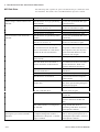
CONTENTS
Contents
GENERAL HANDLING PRECAUTIONS ......................................................................... i
WARRANTY POLICY .................................................................................................... ii
Conventions Used in this Manual and Instrument ........................................................ iv
Warnings, Cautions and Notes ........................................................................... iv
Explanations of the Symbols in this Manual and Instrument .............................. iv
Precautions for Input Jack Use .................................................................................... ix
Section 1
General .................................................................................. 1C.1
Introduction .......................................................................................................................... 1.1
General Information on Servicing ......................................................................................... 1.2
Service Policy, Service Parts and Patient Safety Checks .................................................... 1.4
Service Policy ............................................................................................................ 1.4
Service Parts ............................................................................................................. 1.4
Patient Safety Checks ............................................................................................... 1.5
Maintenance Equipments/Tools .................................................................................. 1.5
General Safety Information .................................................................................................. 1.6
Specifications .................................................................................................................... 1.15
Panel Descriptions .............................................................................................................. 1.19
Component Example ................................................................................................ 1.19
EEG-9100A/J/K/G .......................................................................................... 1.19
EEG-9200A/J/K/G .......................................................................................... 1.19
CC-901AK PC Unit (EEG-9100A/J/K/G) ................................................................... 1.20
CC-902AK PC Unit (EEG-9200A/J/K/G) ................................................................... 1.21
SC-901A/AK/AG Power Supply Unit (for EEG-9200A/J/K/G only) ............................ 1.22
SM-930AA/AJ/AK Isolation Unit (for EEG-9200A/J/K/G only) ................................. 1.22
JE-910A/AG, JE-911A/AG (Option) Electrode Junction Box .................................... 1.23
JE-913A/AG Mini Junction Box (Option) .................................................................. 1.24
LS-901AJ/AK/AG Photo Control Unit (Option) .......................................................... 1.25
Composition ....................................................................................................................... 1.26
EEG-9100A/J/K/G .................................................................................................... 1.26
Standard Components .................................................................................... 1.26
Options .......................................................................................................... 1.26
EEG-9200A/J/K/G .................................................................................................... 1.28
Standard Components .................................................................................... 1.28
Options .......................................................................................................... 1.28
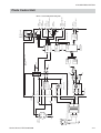
Connection Diagram ........................................................................................................... 1.30
EEG-9100A/J/K/G .................................................................................................... 1.30
EEG-9200A/J/K/G .................................................................................................... 1.31
Section 2
Changing Settings ............................................................... 2C.1
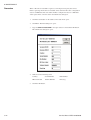
PC Unit Settings .................................................................................................................. 2.1
E11CFG.ini Configuration File .................................................................................... 2.1
Opening the Configuration Settings File Editor Window .................................... 2.1
Service Manual EEG-9100/9200
C.1
CONTENTS
Configuration File List and Settings .................................................................. 2.3
Changing the MO User Label When Installing Two or More Instruments in an Area or
Connecting the Instrument to a Network ............................................................................. 2.15
General ..................................................................................................................... 2.15
Procedure................................................................................................................. 2.15
Section 3
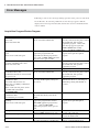
Troubleshooting and Error Messages ............................... 3C.1
How to Troubleshoot ............................................................................................................. 3.1
Closing the Program and Shutting Down Windows ........................................... 3.2
Troubleshooting .................................................................................................................... 3.3
Waveform Acquisition ................................................................................................. 3.3
Skin-electrode Impedance Check ............................................................................... 3.6
Control ........................................................................................................................ 3.7
Activation ................................................................................................................. 3.10
Power ....................................................................................................................... 3.11
Printer ...................................................................................................................... 3.11
MO Disk Drive .......................................................................................................... 3.12
CD-RW Drive (EEG-9200 Only) ................................................................................ 3.13
Error Messages .................................................................................................................. 3.14
Acquisition Program/Review Program ...................................................................... 3.14
File Utility Program ................................................................................................... 3.18
System Program ...................................................................................................... 3.19
Open File Dialog Box ............................................................................................... 3.20
Section 4
Board Description ................................................................ 4C.1
Block Diagram ...................................................................................................................... 4.1
Signal Flow .......................................................................................................................... 4.3
Electrode Junction Box ........................................................................................................ 4.4
EEG INPUT board ...................................................................................................... 4.6
EEG AMP board ........................................................................................................ 4.6
EEG MOTHER Board ................................................................................................. 4.9
Power Supply Unit, SC-901A/AK/AG (for EEG-9100A/J/K/G only) ..................................... 4.10
Isolation Unit, SM-930AA/AJ/AK (for EEG-9200A/J/K/G only) ........................................... 4.10
Photo Control Unit .............................................................................................................. 4.11
PHOTO STIM Board ................................................................................................. 4.12
SWITCH Board ........................................................................................................ 4.13
Section 5
Disassembly ......................................................................... 5C.1
Before You Begin .................................................................................................................. 5.1
Warnings, Cautions and Notes ................................................................................... 5.1
Required Tools ............................................................................................................ 5.2
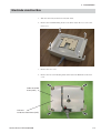
Electrode Junction Box ........................................................................................................ 5.3
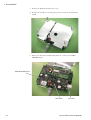
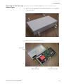
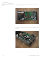
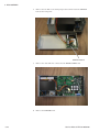
Photo Control Unit ................................................................................................................ 5.6
Removing the Top Cover and Bottom Cover ............................................................... 5.7
Removing the PHOTO STIM Board ............................................................................ 5.8
Removing the SWITCH Board .................................................................................... 5.9
C.2
Service Manual EEG-9100/9200
CONTENTS
Section 6
Maintenance ......................................................................... 6C.1
Checking the Electrode Junction Box ................................................................................... 6.1
Checking Noise .......................................................................................................... 6.1
Required Parts ................................................................................................. 6.1
Checking the Skin-electrode Impedance Check Function .......................................... 6.2
Required Parts ................................................................................................. 6.2
Checking the EEG Input Circuit ................................................................................. 6.3
Required Parts ................................................................................................. 6.3
Checking the Power Supplies ............................................................................................... 6.4
Checking the AC Power Voltage Output from the Power Supply Unit (EEG-9100) ...... 6.4
Checking the AC Power Voltage Output from the Isolation Unit (EEG-9200) .............. 6.4
Checking the Power on the Photo Control Unit ........................................................... 6.5
PHOTIC LAMP Connector ................................................................................ 6.5
Adjusting the Pacing Sound ................................................................................................. 6.6
Checking for Disk Damage Using Check Disk ..................................................................... 6.7
Magneto-Optical Disk ........................................................................................................... 6.8
Checking for Disk Damage Using Scan Disk (EEG-9200 Only) ........................................... 6.9
Writing Down the File and MO Data Before PC Unit or Hard Disk Replacement ................. 6.11
General ..................................................................................................................... 6.11
Procedure................................................................................................................. 6.12
Explanation of Each Setting ..................................................................................... 6.13
Country .......................................................................................................... 6.13
Serial Number ................................................................................................ 6.13
File Number ................................................................................................... 6.14
Fixed tag ........................................................................................................ 6.14
MO User Label ............................................................................................... 6.14
Volume Number .............................................................................................. 6.15
Installing the EEG-9000 System Program .......................................................................... 6.16
General ..................................................................................................................... 6.16
Caution - Before Installation ........................................................................... 6.16
Procedure - EEG-9100 ............................................................................................. 6.17
Installation Flowchart ..................................................................................... 6.17
Step 1 - Installing Windows 2000 Professional ............................................... 6.18
Step 2 - Changing the Screen Resolution ....................................................... 6.20
Step 3 - Turning the Display’s Energy-Saving Feature Off .............................. 6.20
Step 4 - Changing the Visual Effects ............................................................. 6.20
Step 5 - Changing the Hardware Profiles ........................................................ 6.21
Step 6 - Changing the Workgroup Setting ....................................................... 6.21
Step 7 - Checking the IDE Disk Setting ......................................................... 6.21
Step 8 - Changing the Sound Device Setting ................................................. 6.22
Step 9 - Changing the Folder Option Settings ................................................ 6.22
Step 10 - Installing the EEG-9000 System Program ...................................... 6.23
Step 11 - Making the EEG-9000 Shortcut Icon on the Desktop ..................... 6.23
Step 12 - Changing the USB Buffer Size in the Configuration File ................. 6.23
Step 13 - Installing the Electrode Junction Box Driver ................................... 6.24
Step 14 - Changing the Drive Letter ............................................................... 6.26
Procedure - EEG-9200 ............................................................................................. 6.27
Installation Flowchart ..................................................................................... 6.27
Step 1 - Installing Windows 2000 Professional ............................................... 6.28
Service Manual EEG-9100/9200
C.3
CONTENTS
Step 2 - Upgrading the Device Drivers ........................................................... 6.30
Step 3 - Changing the Screen Resolution ....................................................... 6.36
Step 4 - Turning the Display’s Energy-Saving Feature Off .............................. 6.36
Step 5 - Changing the Visual Effects ............................................................. 6.36
Step 6 - Changing the Hardware Profiles ........................................................ 6.37
Step 7 - Changing the Workgroup Setting ....................................................... 6.37
Step 8 - Changing the Folder Option Settings ................................................ 6.37
Step 9 - Installing the EEG-9000 System Program ........................................ 6.38
Step 10 - Making the EEG-9000 Shortcut Icon on the Desktop ..................... 6.38
Step 11 - Changing the USB Buffer Size in the Configuration File ................. 6.38
Step 12 - Installing the Electrode Junction Box Driver ................................... 6.39
Step 13 - Changing the Drive Letter ............................................................... 6.41
Step-14 Installing Roxio Easy CD Creator® 5.1 Basic ................................... 6.42
Internal Switch Settings ..................................................................................................... 6.43
Electrode junction Box ............................................................................................. 6.43
Photo Control Unit .................................................................................................... 6.43
BIOS Default Settings ........................................................................................................ 6.44
PC Unit, CC-901AK (EEG-9100A/J/K/G) .................................................................. 6.44
PC Unit, CC-902AK (EEG-9200A/J/K/G) .................................................................. 6.46
Periodic Replacement Schedule ......................................................................................... 6.48
Maintenance Check Sheet ................................................................................................. 6.49
Overview .................................................................................................................. 6.49
Power ....................................................................................................................... 6.50
Input Circuit and Amplifiers ...................................................................................... 6.51
Operation ................................................................................................................. 6.51
Activation ................................................................................................................. 6.52
Hard Disk, MO Disk Drive and MO Disk .................................................................. 6.52
Safety ...................................................................................................................... 6.52
CD-ROM/CD-RW Disk Drive and CD-R/CD-RW Disk ............................................... 6.53
Section 7
Replaceable Parts List......................................................... 7C.1
Electrode Junction Box ........................................................................................................ 7.2
Photo Control Unit ................................................................................................................ 7.4
LS-703A Flash Lamp Assembly ........................................................................................... 7.6
Section 8
Connector Pin Assignment ................................................ 8C.1
Input/Output Connector/Jack Pin Assignment ..................................................................... 8.1
JE-910A/AG, JE-911A/AG Electrode Junction Box ................................................... 8.1
LS-901AJ/AK/AG Photo Control Unit ......................................................................... 8.3
JE-913A/AG Mini Junction Box .................................................................................. 8.6
C.4
Service Manual EEG-9100/9200
GENERAL HANDLING PRECAUTIONS
This device is intended for use only by qualified medical personnel.
Use only Nihon Kohden approved products with this device. Use of non-approved products or
in a non-approved manner may affect the performance specifications of the device. This
includes, but is not limited to, batteries, recording paper, pens, extension cables, electrode
leads, input boxes and AC power.
Please read these precautions thoroughly before attempting to operate the instrument.
1. To safely and effectively use the instrument, its operation must be fully understood.
2. When installing or storing the instrument, take the following precautions:
(1) Avoid moisture or contact with water, dust, extreme atmospheric pressure, excessive humidity and temperatures,
poorly ventilated areas, and saline or sulphuric air.
(2) Place the instrument on an even, level floor. Avoid vibration and mechanical shock, even during transport.
(3) Avoid placing in an area where chemicals are stored or where there is danger of gas leakage.
(4) The power line source to be applied to the instrument must correspond in frequency and voltage to product
specifications, and have sufficient current capacity.
(5) Choose a room where a proper grounding facility is available.
3. Before Operation
(1) Check that the instrument is in perfect operating order.
(2) Check that the instrument is grounded properly.
(3) Check that all cords are connected properly.
(4) Pay extra attention when the instrument is in combination with other instruments to avoid misdiagnosis or other
problems.
(5) All circuitry used for direct patient connection must be doubly checked.
(6) Check that battery level is acceptable and battery condition is good when using battery-operated models.
4. During Operation
(1) Both the instrument and the patient must receive continual, careful attention.
(2) Turn power off or remove electrodes and/or transducers when necessary to assure the patient’s safety.
(3) Avoid direct contact between the instrument housing and the patient.
5. To Shutdown After Use
(1) Turn power off with all controls returned to their original positions.
(2) Remove the cords gently; do not use force to remove them.
(3) Clean the instrument together with all accessories for their next use.
6. The instrument must receive expert, professional attention for maintenance and repairs. When the instrument is
not functioning properly, it should be clearly marked to avoid operation while it is out of order.
7. The instrument must not be altered or modified in any way.
8. Maintenance and Inspection:
(1) The instrument and parts must undergo regular maintenance inspection at least every 6 months.
(2) If stored for extended periods without being used, make sure prior to operation that the instrument is in perfect
operating condition.
Service Manual EEG-9100/9200
i
(3) Technical information such as parts list, descriptions, calibration instructions or other information is available for
qualified user technical personnel upon request from your Nihon Kohden distributor.
9. When the instrument is used with an electrosurgical instrument, pay careful attention to the application and/or
location of electrodes and/or transducers to avoid possible burn to the patient.
10. When the instrument is used with a defibrillator, make sure that the instrument is protected against defibrillator
discharge. If not, remove patient cables and/or transducers from the instrument to avoid possible damage.
WARRANTY POLICY
Nihon Kohden Corporation (NKC) shall warrant its products against all defects in materials and workmanship for one year
from the date of delivery. However, consumable materials such as recording paper, ink, stylus and battery are excluded from
the warranty.
NKC or its authorized agents will repair or replace any products which prove to be defective during the warranty period,
provided these products are used as prescribed by the operating instructions given in the operator’s and service manuals.
No other party is authorized to make any warranty or assume liability for NKC’s products. NKC will not recognize any other
warranty, either implied or in writing. In addition, service, technical modification or any other product change performed by
someone other than NKC or its authorized agents without prior consent of NKC may be cause for voiding this warranty.
Defective products or parts must be returned to NKC or its authorized agents, along with an explanation of the failure.
Shipping costs must be pre-paid.
This warranty does not apply to products that have been modified, disassembled, reinstalled or repaired without Nihon
Kohden approval or which have been subjected to neglect or accident, damage due to accident, fire, lightning, vandalism,
water or other casualty, improper installation or application, or on which the original identification marks have been
removed.
In the USA and Canada other warranty policies may apply.
CAUTION
United States law restricts this device to sale by or on the order of a physician.
ii
Service Manual EEG-9100/9200
EMC RELATED CAUTION
This equipment and/or system complies with the International Standard IEC60601-1-2 for electromagnetic
compatibility for medical electrical equipment and/or system. However, an electromagnetic environment
that exceeds the limits or levels stipulated in the IEC60601-1-2, can cause harmful interference to the
equipment and/or system or cause the equipment and/or system to fail to perform its intended function or
degrade its intended performance. Therefore, during the operation of the equipment and/or system, if
there is any undesired deviation from its intended operational performance, you must avoid, identify and
resolve the adverse electromagnetic effect before continuing to use the equipment and/or system.
The following describes some common interference sources and remedial actions:
1.Strong electromagnetic interference from a nearby emitter source such as an authorized radio station or
cellular phone:
Install the equipment and/or system at another location if it is interfered with by an emitter source such
as an authorized radio station. Keep the emitter source such as cellular phone away from the equipment
and/or system.
2.Radio-frequency interference from other equipment through the AC power supply of the equipment and/
or system:
Identify the cause of this interference and if possible remove this interference source. If this is not
possible, use a different power supply.
3.Effect of direct or indirect electrostatic discharge:
Make sure all users and patients in contact with the equipment and/or system are free from direct or
indirect electrostatic energy before using it. A humid room can help lessen this problem.
4.Electromagnetic interference with any radio wave receiver such as radio or television:
If the equipment and/or system interferes with any radio wave receiver, locate the equipment and/or
system as far as possible from the radio wave receiver.
If the above suggested remedial actions do not solve the problem, consult your Nihon Kohden
Corporation subsidiary or distributor for additional suggestions.
The CE mark is a protected conformity mark of the European Community. The products herewith comply
with the requirements of the Medical Device Directive 93/42/EEC.
The CE mark is only applied to the EEG-9100K/G and EEG-9200K/G Electroencephalograph.
This equipment complies with EUROPEAN STANDARD EN-60601-1-2 (1993) which requires EN-55011,
class B.
Service Manual EEG-9100/9200
iii
Conventions Used in this Manual and Instrument
Warnings, Cautions and Notes
Warnings, cautions and notes are used in this manual to alert or signal the reader to specific information.
WARNING
A warning alerts the user to the possible injury or death associated with the use or misuse of the
instrument.
CAUTION
A caution alerts the user to possible injury or problems with the instrument associated with its use or
misuse such as instrument malfunction, instrument failure, damage to the instrument, or damage to other
property.
NOTE
A note provides specific information, in the form of recommendations, prerequirements, alternative
methods or supplemental information.
Explanations of the Symbols in this Manual and Instrument
The following symbols found in this manual/instrument bear the respective descriptions as given.
Power supply unit, SC-901A/AK/AG (for EEG-9100A/J/K/G)
Isolation unit, SM-930AA/AJ/AK (for EEG-9200A/J/K/G)
Symbol
Description
Description
Alternative current
Attention, consult operator’s
manual
Equipotential ground terminal
Serial number
Protective ground
Date of manufacture
The CE Mark is a protected
conformity mark of the
European Community. The
products herewith comply with
the requirements of the Medical
Device Directive 93/42/EEC.
iv
Symbol
EMC
The product complies with
IEC60601-1-2 (1993)
(for sales in Japan only)
Service Manual EEG-9100/9200
PC unit, CC-901AK (for EEG-9100A/J/K/G)
Symbol
Description
Symbol
Description
Power/suspend indicator
RS-232C connector
9
Num Lock indicator
Mouse connector
A
Caps Lock indicator
USB connector
Scroll Lock indicator
PRT connector
Hard disk access lamp indicator
Unlock icon
Battery charging indicator
Protective ground
Power socket
Attention, consult operator’s
manual
Symbols on the PC unit differ according to model. Refer to the Operator’s manual of the PC unit.
For the symbols of the following equipments, refer to each Operator’s manual.
• Magneto-optical disk drive
• Printer
Service Manual EEG-9100/9200
v
PC unit, CC-902AK (for EEG-9200A/J/K/G)
Symbol
Description
Symbol
Description
Standby (power on/off)
USB connector
Hard disk access lamp
Video connector
Headphone connector
Network connector
Printer port
Audio jack (Microphone)
Serial port
Audio jack (LINE OUT)
Mouse connector
Audio jack (LINE IN)
Keyboard connector
Attention, consult operator’s
manual
Protective ground
Symbols on the PC unit differ according to model. Refer to the Operator’s manual of the PC unit.
For the symbols of the following equipments, refer to each Operator’s manual.
• Display
• Magneto-optical disk drive
• Laser printer
vi
Service Manual EEG-9100/9200
Options
Electrode junction box, JE-910A/AG, JE-911A/AG
Symbol
Description
Symbol
Description
Attention, consult operator’s
manual
Type BF applied part
Flash lamp assembly, LS-703A/LS-706A
Symbol
Description
Symbol
Description
Attention, consult operator’s
manual
Hot surface
Photo control unit, LS-901AJ/AK/AG
Symbol
Description
Symbol
Description
Attention, consult operator’s
manual
Serial number
Alternative current
Date of manufacture
Equipotential ground terminal
Photo control unit (inside)
Symbol
Description
High voltage
Symbol
Description
Ground
Protective ground
Service Manual EEG-9100/9200
vii
On screen
Symbol
Description
Description
Display of list box
Warning query that displays a
warning or caution for
operation.
Scrolling of data, list and others
Warning message that displays a
warning or caution for operation
you to do something.
Check box
Option button
viii
Symbol
Maximize Restore Minimize
Window maximize/resize
minimize button
Close button
Service Manual EEG-9100/9200
Precautions for Input Jack Use
NOTE
Do not perform EEG measurement without the Z, C3, C4, A1 and A2 electrodes.
Use of input jack Z
Connect the lead from the electrode (Z electrode) attached on the patient’s nasion to the input jack Z on the electrode
junction box. The purpose of this input jack is to eliminate AC interference positively.
NOTE
The input jack Z is also used for checking electrode impedance.
Use of input jacks C3 and C4
Connect the leads from the electrodes attached on the positions C3 and C4 to the input jacks C3 and C4 respectively.
NOTE
• The C3 and C4 electrodes are the system reference electrodes for EEG measurement.
• The input jacks C3 and C4 must be attached for EEG measurement even when the C3 and C4 are not
programmed in any montage.
Use of input jacks A1 and A2 (or FP1 and FP2), C3 and C4 during skin-electrode impedance check
When checking each electrode impedance, connect the leads from the electrode attached on the positions A1, A2, C3 and C4
to the input jacks A1, A2, C3 and C4 respectively.
NOTE
• The A1 and A2 (or FP1 and FP2) electrodes are the reference electrodes for skin-electrode impedance
check.
• The input jacks A1 and A2 (or FP1 and FP2) in addition to the Z, C3 and C4 must be attached for the
electrode impedance check.
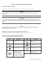
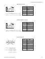
PG1
PG2
22
23
Z
FP1
FP2
1
T1
25
F7
13
Fz
11
F3
3
T3
15
C3
4
Cz
24
20
T2
26
T4
16
P4
8
OI
9
F8
14
C4
6
Pz
P3
7
F4
Fz
19
5
T5
17
2
A2
12
T6
18
O2
10
Checking original electrode potentials for all active electrodes
Check the original electrode potential for all active electrodes by programming a montage with the system reference (Select
the 0 V button for reference electrode on the Montage dialog box). Refer to “Programming Patterns” in Section 4.
The digital EEG displays the EEG waveform in each channel by subtracting two electrode potentials selected to a montage.
The subtracted result will be incorrect, if the electrode attachment is not correct, the original electrode potential is flat or
unstable, or artifact is superimposed on the original electrode potential. Omit the measurement result if the displayed EEG
waveform is incorrect.
Service Manual EEG-9100/9200
ix
This page is intentionally left blank.
x
Service Manual EEG-9100/9200
Section 1 General
Introduction ........................................................................................................................ 1.1
General Information on Servicing ...................................................................................... 1.2
Service Policy, Service Parts and Patient Safety Checks .................................................. 1.4
Service Policy .......................................................................................................... 1.4
Service Parts ........................................................................................................... 1.4
Patient Safety Checks .............................................................................................. 1.5
Maintenance Equipments/Tools ............................................................................... 1.5
General Safety Information ................................................................................................ 1.6
Specifications ................................................................................................................... 1.15
Panel Descriptions ........................................................................................................... 1.19
Component Example ............................................................................................. 1.19
EEG-9100A/J/K/G ....................................................................................... 1.19
EEG-9200A/J/K/G ....................................................................................... 1.19
CC-901AK PC Unit (EEG-9100A/J/K/G) ................................................................ 1.20
CC-902AK PC Unit (EEG-9200A/J/K/G) ................................................................ 1.21
SC-901A/AK/AG Power Supply Unit (for EEG-9200A/J/K/G only) ......................... 1.22
SM-930AA/AJ/AK Isolation Unit (for EEG-9200A/J/K/G only) ................................ 1.22
JE-910A/AG, JE-911A/AG (Option) Electrode Junction Box .................................. 1.23
JE-913A/AG Mini Junction Box (Option) ................................................................ 1.24
LS-901AJ/AK/AG Photo Control Unit (Option) ....................................................... 1.25
Composition ..................................................................................................................... 1.26
EEG-9100A/J/K/G .................................................................................................. 1.26
Standard Components ................................................................................. 1.26
Options ........................................................................................................ 1.26
EEG-9200A/J/K/G .................................................................................................. 1.28
Standard Components ................................................................................. 1.28
Options ........................................................................................................ 1.28
Connection Diagram ........................................................................................................ 1.30
EEG-9100A/J/K/G .................................................................................................. 1.30
EEG-9200A/J/K/G .................................................................................................. 1.31
Service Manual EEG-9100/9200
1C.1
This page is intentionally left blank.
1C.2
Service Manual EEG-9100/9200
1. GENERAL
Introduction
This service manual provides useful information to qualified service personnel to
understand, troubleshoot, service, maintain and repair this EEG-9100A/J/K/G and
EEG-9200A/J/K/G Electroencephalograph (referred to as “instrument” in this
service manual.
All replaceable parts or units of this instrument and its optional units are clearly
listed with exploded illustrations to help you locate the parts quickly.
The “Maintenance” section in this service manual only describes the maintenance
that should be performed by qualified service personnel. The Maintenance section
in the operator’s manual describes the maintenance that can be performed by the
user.
The information in the operator’s manual is primarily for the user. However, it is
important for service personnel to thoroughly read the operator’s manual and
service manual before starting to troubleshoot, service, maintain or repair this
instrument. This is because service personnel needs to understand the operation of
the instrument in order to effectively use the information in the service manual.
CAUTION
To turn the power off, follow the procedure in “Power Off Procedure”
in Section 3 of the Operator’s manual. Do not press the power button
on the PC unit. If the power button is pressed while a program is
running, the program, data file in the hard disk and/or MO disk may be
damaged.
Trademarks
Dell is a registered trademark of Dell Computer Corporation.
Windows is a registered trademarks of Microsoft Corporation.
Celeron is a trademark of Intel Corporation.
Canon is a registered trademark of Canon Corporation.
Fujitsu is a registered trademark of Fujitsu Limited.
Pentium is a trademark of Intel Corporation.
HP is a registered trade mark of Hewlette-Packard Company
SONY is a registered trade mark of Sony Corporation.
EIZO is a registered trade mark of EIZO NANAO Corporation
Service Manual EEG-9100/9200
1.1
1. GENERAL
General Information on Servicing
Note the following information when servicing the system.
CAUTIONS
Safety
• There is the possibility that the outside surface of the system, such as
the operation keys, could be contaminated by contagious germs, so
disinfect and clean the system before servicing it. When servicing the
system, wear rubber gloves to protect yourself from infection.
• There is the possibility that when the lithium battery is broken, a
solvent inside the lithium battery could flow out or a toxic substance
inside it could come out. If the solvent or toxic substance touches
your skin or gets into your eye or mouth, immediately wash it with a
lot of water and see a physician.
Liquid ingress
The system is not waterproof, so do not install the system where water
or liquid can get into or fall on the system. If liquid accidentally gets
into the system or the system accidentally drops into liquid,
disassemble the system, clean it with clean water and dry it
completely. After reassembling, verify that there is nothing wrong
with the patient safety checks and function/performance checks. If
there is something wrong with the system, contact your Nihon Kohden
representative to repair.
Environmental Safeguards
Depending on the local laws in your community, it may be illegal to
dispose of the lithium battery in the regular waste collection. Check
with your local officials for proper disposal procedures.
Disinfection and cleaning
To disinfect the outside surface of the system, wipe it with a nonabrasive cloth moistened with any of the disinfectants listed below.
Do not use any other disinfectants or ultraviolet rays to disinfect the
system.
- Chlorohexidine gluconate solution:
0.5%
- Benzethonium chloride solution:
0.2%
- Glutaraldehyde solution:
2.0%
- Benzalkonium chloride:
0.2%
- Hydrochloric alkyl diaminoethylglycine:
0.5%
1.2
Service Manual EEG-9100/9200
1. GENERAL
Caution - continued
Transport
• Use the specified shipment container and packing material to
transport the system. If necessary, double pack the system. Also, put
the system into the shipment container after packing so that the buffer
material does not get into the inside of the system.
• When transporting a board or unit of the system, be sure to use a
conductive bag. Never use an aluminum bag when transporting a
board or unit which a lithium battery is mounted. Also, never use a
styrene foam or plastic bag which generates static electricity to wrap
the board or unit of the system.
Handling the system
• Because the outside surface of the system is made of resin, the
outside surface of the system is easily damaged. So when handling
the system, remove clutter from around the system and be careful to
not damage the system or get it dirty.
• Because most of the boards in the system are multilayer boards with
surface mounted electrical devices (SMD), when removing and
soldering the electrical devices, a special tool is required. To avoid
damaging other electrical components, do not remove and solder
SMD components yourself.
Measuring and Test Equipment
Maintain the accuracy of the measuring and test equipment by
checking and calibrating it according to the check and calibration
procedures.
Service Manual EEG-9100/9200
1.3
1. GENERAL
Service Policy, Service Parts and Patient Safety Checks
Service Policy
Our technical service policy for this instrument is to replace the faulty unit, board
or part or damaged mechanical part with a new one. Do not perform electrical
device or component level repair of the multilayer board or unit. We do not support
component level repair outside the factory for the following reasons:
• Most of the boards are multilayer boards with surface mounted electrical
devices, so the mounting density of the board is too high.
• A special tool or high degree of repair skill is required to repair the multilayer
boards with surface mounted electrical devices.
Disassemble the instrument or replace a board or unit in an environment where the
instrument is protected against static electricity.
As background knowledge for repair, pay special attention to the following:
• You can reduce the repair time by considering the problem before starting repair.
• You can clarify the source of most of the troubles using the information from the
troubleshooting tables. Refer to “Troubleshooting“ of this manual.
Service Parts
Refer to “Replaceable Parts List” of this manual for the service parts for technical
service that we provide.
NOTE
When ordering parts or accessories from your Nihon Kohden
representative, please quote the NK code number and part name
which is listed in this service manual, and the name or model of the
unit in which the required part is located. This will help us to
promptly attend to your needs. Always use parts and accessories
recommended or supplied by Nihon Kohden Corporation to assure
maximum performance from your instrument.
1.4
Service Manual EEG-9100/9200
1. GENERAL
Patient Safety Checks
Periodic maintenance procedures and diagnostic check procedures are provided in
this manual to ensure that the instrument is operating in accordance with its design
and production specifications. To verify that the instrument is working in a safe
manner with regard to patient safety, patient safety checks should be performed on
the instrument before it is first installed, periodically after installation, and after any
repair is made on the instrument.
For patient safety checks, perform the following checks as described in the
IEC60601-1 “Medical electrical equipment - Part 1: General requirements for
safety”:
• Protective earth resistance check
• Earth leakage current check
• Enclosure leakage current check
• Patient leakage current check
• Withstanding voltage check
Maintenance Equipments/
Tools
Test equipment
When repairing or calibrating the instrument, the following test equipment is
required.
• Oscilloscope: 2 channels or more for input signal, 50 mV to 5 V input range, 1/
10 attenuating probe and 100 MHz or more frequency response characteristic
must be provided.
• Oscillator: standard type
• Digital voltmeter: standard type (An oscilloscope can be used instead of the
digital voltmeter.)
Checking tool
When checking the internal noise of the electrode junction box and skin-electrode
impedance check function, the checking tools are necessary. Refer to Section 7
“Maintenance”.
Service Manual EEG-9100/9200
1.5
1. GENERAL
General Safety Information
WARNING
• Never use this instrument in the presence of any flammable anesthetic
gas or high-concentration oxygen atmosphere. Failure to follow this
warning may cause explosion or fire.
• Never use this instrument in a high-pressure oxygen medical tank.
Failure to follow this warning may cause explosion or fire.
Using with an electrical surgical unit (ESU)
• Never use this instrument near an ESU. The instrument may
malfunction due to high-frequency noise from the ESU.
• When using this instrument with an ESU, refer to the instruction
manual for the ESU. Before measurement, check that the return plate
is correctly attached to the patient and check that the instrument
operates correctly when using with the ESU. If the return plate is not
attached correctly, it may burn the patient’s skin where the electrodes
are attached.
• Before using the ESU, remove all needle electrodes and silver ball
electrodes from the patient. Failure to follow this warning may cause
burn on the patient.
MRI examination
• Do not install this instrument in an MRI examination room. The
instrument may not operate properly due to high-frequency magnetic
noise from the MRI.
• When performing MRI tests, remove from the patient all the electrodes
and transducers which are connected to this instrument. Failure to
follow this warning may cause serious electrical burn on the patient
due to local heating caused by dielectric electromotive force. For
details, refer to the instruction manual for the MRI.
When performing defibrillation
• Before defibrillation, remove from the patient all electrodes and
transducers which are connected to connectors that do not have a
“
” or “
” mark. The discharged energy may cause serious
electrical burn or shock to the operator.
• Before defibrillation, remove all electrodes and gel from the chest of
the patient. If the defibrillator paddle touches electrodes or gel, the
discharged energy may burn the patient’s skin.
• Before defibrillation, all persons must keep clear of the bed and must
not touch the patient or any equipment connected to the patient.
Failure to follow this warning may cause serious electrical burn,
shock or other injury.
1.6
Service Manual EEG-9100/9200
1. GENERAL
Installation
WARNING
• Do not install the QP-0042/0043 EEG-9000 System program into a
personal computer which is not specified by Nihon Kohden and use it
for EEG measurement.
- If the personal computer does not satisfy the performance
specifications and safety standards which are required by Nihon
Kohden, the patient and operator may get electrical shock.
- Nihon Kohden does not warrant if hardware and/or software
becomes defective after installation.
• Only use the provided power cords. If another power cord is used, it
may cause electrical shock to the patient and operator.
• For patient safety, equipotential grounding of all instruments must be
performed. Consult a qualified biomedical engineer.
• Use the SC-901A/AK/AG Power Supply Unit (EEG-9100A/J/K/G) or SM930AA/AJ/AK Isolation Unit (EEG-9200A/J/K/G) to supply AC power to
a PC unit, display (EEG-9200A/J/K/G only) and an MO disk drive.
When two or more power supply units or isolation units are used,
ground the power supply units or isolation units to the same
equipotential ground and connect the power supply units or isolation
units to the same AC outlet to prevent electrical potential difference
between the power supply units or isolation units. Never use a
locally available multi-power outlets. Failure to follow this warning
may cause electrical shock to the patient and operator.
Display (EEG-9200A/J/K/G only)
• The display must comply with the IEC950 standard and CISPR11
Second Edition 1990-09 Group 1 and Class B standard, or the
equivalent.
• Only supply AC power from the SM-930AA/AJ/AK Isolation Unit. Do
not connect the display to a wall AC outlet. Failure to follow this
warning may cause electrical shock to the patient and operator.
Magneto-optical disk drive
• The MO disk drive must comply with the IEC950 standard and
CISPR11 Second Edition 1990-09 Group 1 and Class B standard, or the
equivalent.
• Only supply AC power from the SC-901A/AK/AG Power Supply Unit
(EEG-9100A/J/K/G) or from the SM-930AA/AJ/AK Isolation Unit (EEG9200A/J/K/G). Do not connect the MO disk drive to a wall AC outlet.
Failure to follow this warning may cause electrical shock to the
patient and operator.
Service Manual EEG-9100/9200
1.7
1. GENERAL
Warning - continued
* Patient environment
Any area in which intentional or
unintentional contact between
PATIENT and parts of SYSTEM or
some other persons touching of the
SYSTEM can occur.
Printer
• The printer must comply with the IEC950 standard and CISPR11
Second Edition 1990-09 Group 1 and Class B standard, or the
equivalent.
• Mount the printer on the KE-910A Cart (EEG-9100A/J/K/G) or KD-024A
Cart (EEG-9200A/J/K/G) and supply AC power from the SC-901A/AK/AG
Power Supply Unit (EEG-9100A/J/K/G) or SM-800RJ/RK Isolation Unit
(EEG-9200A/J/K/G) . Do not connect the printer to a wall AC outlet.
Failure to follow this warning may cause electrical shock to the
patient and operator.
• When the printer is not mounted on the KE-910A Cart or KD-024A Cart,
locate the printer outside the patient environment (IEC60601-1-1 2.204*)
and supply AC power from a medical isolation transformer. Do not
connect the printer to a wall AC outlet. Failure to follow this warning
may cause electrical shock to the patient and operator.
• Connect only the specified instruments to the connectors or socket
marked with
, by following the specified procedure. Otherwise,
electrical leakage current may harm the patient and operator.
• When the instrument is turned on, about 600 V is present at pin 2 of
the PHOTIC LAMP connector on the LS-901AJ/AK/AG Photo control
unit. To protect against shock, always connect the flash lamp
assembly cable to this connector, or attach the PHOTOTIC LAMP
connector cap to the PHOTIC LAMP connector even when the photic
stimulation is not used.
• When connecting an external instrument to the connectors marked
with , the external instrument and this instrument must be
connected according to the IEC-60601-1-1 “Medical electrical
equipment - Part 1-1: General requirements for safety - Collateral
standard: Safety requirements for medical electrical systems”. Failure
to follow this warning may cause electrical shock to the patient and
operator.
Connecting to a Local Area Network
• When connecting the instrument to a local area network, connect the
instrument so that the instrument is electrically separated from the
local area network according to the IEC-60601-1-1 “Medical electrical
equipment - Part 1-1: General requirements for safety - Collateral
standard: Safety requirements for medical electrical systems”. Failure
to follow this warning may cause electrical shock to the patient and
operator.
• Check that there is no damage on the surface of the network cable. If
it is damaged, it may cause electrical shock to the patient and
operator.
1.8
Service Manual EEG-9100/9200
1. GENERAL
Warning - continued
• Before connecting or disconnecting the DC input cable to the DC input
connector on the JE-911A/AG Electrode junction box, make sure that
the power of the external instrument is turned off or DC signal is not
output from the external instrument. Failure to follow this warning
may cause electrical shock to the patient and operator.
CAUTION
• When connecting the cables, make sure that each instrument is turned
off.
• Connect only the CC-901AK PC unit and MO disk drive to the SC-901A/
AK/AG power supply unit. If other equipment is connected, the power
supply unit may not supply enough AC power and may cause
malfunction.
• Connect only the CC-902AK PC unit, display and MO disk drive to the
SM-930AA/AJ/AK Isolation Unit. If other equipment is connected, the
isolation unit may not supply enough AC power and may cause
malfunction.
• Only install the specified software in the instrument. Otherwise the
system may malfunction.
• When moving the instrument, select a flat path and move it carefully
to prevent the components from falling off or the cart from tipping
over.
• If static electricity is applied to the connector for the optional
hyperventilation unit, pulse noise may be superimposed on the
waveform of the mark channel.
• When using the instrument in a high-frequency electric field, the
displayed waveform trace may be thicker.
• Use a printer cable which does not emit an unwanted radio frequency
signal (EMC protected).
Service Manual EEG-9100/9200
1.9
1. GENERAL
Caution - continued
Cart
• Use only the KE-910A Cart (EEG-9100A/J/K/G) or KD-024A/025A (EEG9200A/J/K/G) for this instrument. If any of these carts is not used,
secure the components of the instrument so that they do not fall off or
tip over.
• Do not sit or lean on the cart because it may tip over.
• Set the components of the electroencephalograph on the cart
according to the specified procedures. Otherwise, the cart may break
or the components may tip over.
• Align the cable with the cable tie or cable clamp so that the cable is
not accidentally pulled or caught. Otherwise, the connector may be
damaged or the components connected on the cart may fall off and
cause injury.
• Do not use the SD-901AJ/AK/AG (EEG-9100A/J/K/G), SD-903AJ/AK/AG
(EEG-9200A/J/K/G) Multiple Portable Socket Outlet if it is not secured
to the cart. Otherwise, it may cause electrical shock to the patient and
operator.
• When moving the cart,
- make sure that the power of all components are turned off,
- close the PC unit display (EEG-9100A/J/K/G - CC-901AK),
- release the caster lock,
- only grip the handle,
- select a flat path and move the cart carefully to prevent tipping over,
components falling or impact, and
- take care so that the electrode junction box or flash lamp assembly
does not bump into a surrounding instrument.
• Periodically check that the caster rotates smoothly and that no screw
or knob bolt is loose.
1.10
Service Manual EEG-9100/9200
1. GENERAL
Operation
WARNING
• When using the instrument for brain death diagnosis, before
examination, check and adjust the date and time of the system. The
date and time on the screen and on the recording result are part of
important information for the medical record.
• Do not connect the Z electrode lead plug to a ground or equipotential
ground. Otherwise, leakage current from another instrument cause
electrical shock to the patient.
• When the JE-913A/AG mini junction box is not used, make sure that
the multiple connecter cover is firmly attached to the electrode
junction box. Failure to follow this warning may cause electrical
shock to the patient and operator.
• All activation testing must be applied under the supervision of the
physician in charge. Mouth gags, tongue depressors and gauze
sponges must always be prepared for use to prevent the patient from
biting his tongue or injuring himself during testing because any
pattern of flash stimuli may induce seizure activity.
• Do not perform hyperventilation activation when the patient has
serious heart disease, acute cerebrovascular disease or respiratory
insufficiency.
• When performing the photic stimulation, If an abnormal waveform
appears due to photo-paroxymal response, stop the photic stimulation
immediately to prevent evoking seizure.
When using the NE-224S Sub-dermal Straight Needle Electrode
• Do not use the NE-224S sub-dermal straight needle electrode as a
measurement electrode for the EEG or evoked potential measurement
for any longer than one hour. When measuring the EEG or evoked
potential for over one hour, use the EEG disk electrode.
• Do not check the skin-electrode impedance when using a needle
electrode or intracranial electrode. Failure to follow this warning
injures the patient because these electrodes will be damaged by
electrolyzation inside the body.
• Only connect the respiration pickup which is specified by Nihon
Kohden to the RESP F, C, A jack. If an unspecified respiration pickup,
sensor or equipment is connected, electrical leakage current may
harm the patient and operator.
Service Manual EEG-9100/9200
1.11
1. GENERAL
CAUTION
• During measurement, do not change the date and time. This makes
the order of the saved event data and the time of the saved waveforms
incorrect.
• Do not use the photic stimulator continuously over 5 minutes in any
mode. When photic stimulation is performed for a long time, the flash
lamp assembly gets very hot and causes burn if touched. If the photic
stimulator is continuously used for 5 minutes, do not use it for at least
20 minutes to let it cool down.
• Do not turn the instrument off when the program is running.
When turning the instrument off, follow the procedure in “Power Off
Procedure” in Section 2.
• Do not delete any system file in the hard disk. Otherwise the
instrument may malfunction.
• Do not remove the optical disk or magneto-optical disk until the disk
drive access lamp is off. Otherwise, the disk or disk drive may be
damaged.
• Periodically back up the EEG data files to prevent loss of data when
the hard disk or MO disk is damaged.
NOTE
• If any static electricity enters the electrode junction box or serial input
terminal, spike noise may be superimposed on the waveform.
• If static electricity is applied to the connector for the optional
hyperventilation unit, pulse noise may be superimposed on the
waveform of the mark channel.
• When using the instrument in a high-frequency electric field, the
displayed waveform trace may be thicker.
Disinfecting or Sterilizing
CAUTION
Turn off the power before cleaning or disinfecting. Otherwise you may
get an electrical shock or the instrument may malfunction.
1.12
Service Manual EEG-9100/9200
1. GENERAL
Floppy Disk/CD-ROM Disk
Handling and Storing
WARNING
The QP-0042/QP-0043 EEG-9000 System Program is protected by
copyright law and international treaties. Unauthorized reproduction or
distribution of this software, or any portion of it, may result in severe
civil and criminal penalties, and will be prosecuted to the maximum
extent possible under law.
CAUTION
• Keep floppy disks away from strong magnetic objects such as a
magnet, TV set or speaker. Otherwise, data in the disk may be lost.
• Do not insert or remove a disk while the lamp on the disk unit is lit.
• During measurement, do not insert or remove a CD-R or CD-RW disk
into the CD-RW drive. Otherwise, the Acquisition program may
malfunction (EEG-9200A/J/K/G).
• Do not touch the disk surface of the recorded side (CD-ROM: opposite
side of the label side). If the surface of the disk becomes
contaminated with any foreign substances such as fingerprints,
reading data may be impossible.
• Keep the disk away from direct sunlight and high temperature.
Otherwise, the disk may become deformed.
• Do not handle the disk while smoking or eating.
• Do not get the disk wet.
• Do not put a label on top of another label. Remove the old label
before applying a new label.
• Do not write on the label after the label is attached on the disk.
Otherwise, the disk may be damaged and reading may be impossible.
• Do not bend the disk, put heavy material on the disk, or give a strong
impact to the disk.
• Clean the disk with a disk cleaner. Do not use organic solvents such
as acetone.
• This CD–ROM is not an audio CD and cannot be played with an audio
CD player.
Service Manual EEG-9100/9200
1.13
1. GENERAL
NOTE
• When using the EEG-9000 application program, close all other
programs. Otherwise, the System Program may not function properly.
• Turn off any screen saver before opening the EEG-9000 application
program.
1.14
Service Manual EEG-9100/9200
1. GENERAL
Specifications
Data Acquisition
Number of input jacks
EEG inputs on electrode position layout: 25
Extra inputs:
4 (X1 to X4)
Reference input for feedback:
1 (Z)
Respiration inputs:
3 {RESP F (flow), RESP C (chest), RESP A (abdomen)}
Bipolar inputs
6 (3 pairs)
DC input:
4 (JE-911A/AG only)
Input impedance
100 MΩ
Input leakage current
less than 5 nA
Internal noise level
Less than 1.5 µVp-p (0.53 to 60 Hz)
CMRR
105 dB or greater (at 60 Hz)
Gain
× 469.73
Low-cut filter
0.08 Hz (time constant: 2 s )
High-cut filter
300 Hz (-18 dB/oct)
Offset tolerance
±750 mV
A/D conversion
16 bits (97 nV/LSB)
Sampling and hold
All electrodes at the same time
Sampling frequency
1,000 Hz
Data Processing
Sensitivity
EEG INPUT:
DC INPUT:
Time constant
(Low-cut filter)
High-cut filter
AC filter
Calibration waveform
Waveform shape:
Voltage:
ECG elimination filter
Impedance check
Indication on the screen:
Indication on LED:
Impedance threshold:
Pattern
Reference electrode selector
Marking signal
Service Manual EEG-9100/9200
OFF, 1, 2, 3 (2.5), 5, 7, 10, 15, 20, 30, 50, 75, 100, 150, 200 µV/mm
OFF, 10, 15, 20, 30, 50, 70, 100, 150, 200 mV/mm
0.001, 0.003, 0.03, 0.1, 0.3, 0.6, 1.0, 2.0 s
0.08, 0.16, 0.27, 0.53, 1.6, 5.3, 53, 159 Hz (-6 dB/oct)
15, 30, 35, 60, 70, 120 (-12 dB/oct),
50 (RAPID), 300 Hz (-18 dB/oct)
50 or 60 Hz, (rejection ratio: 1/25 or more)
0.25 Hz step wave or 10 Hz sine wave
2, 5, 10, 20, 50, 100, 200, 500, 1,000 µV (× 1000 for DC input signal)
Available in acquisition and review programs
All electrodes are displayed on the screen in electrode position layout.
Impedance for each electrode is displayed and electrodes with impedance
higher than the preset impedance threshold are highlighted.
LEDs on the electrode junction box with impedance higher than the preset
impedance threshold light.
2, 5, 10, 20 and 50 kΩ
36 sets of programmable montages combined with programmable
individual amplifier settings
A1 →A2, A1 ←A2, A1 ↔ A2, A1 + A2, VX, AV (with unsuitable electrode
deletion function), Aav, Org, SD and OFF.
Photic stimulation mark, Hyperventilation mark
1.15
1. GENERAL
Display
Display resolution
Number of display channels
Display modes
Waveform display color
Waveform display on/off
Waveform position adjustment
Waveform freeze
Paient image display
Waveform sweep speed
Timing mark
Time scale
Event mark
EEG scale
Acquisition Program
Timer function
Data storage device
Sampling frequency
Manual timer, recording timer, HV timer
Hard disk drive (standard), magneto-optical disk drive (option)
100, 200, 500, 1000 Hz
Photic Stimulator
Maximum flash energy
Stimulation modes
Mode of operation
Duty cycle
0.64 J or more
3 automatic (30 steps, programmable), manual, and single
Continuous operation with intermittent loading
Max. 5 minutes continuous operation in 30 minutes
Automatic stimulation
Stimulus rate
Stimulation period
Pause period
0.5, 1 to 33 (1 Hz steps), 50 and 60 Hz
1 to 99 seconds in 1 second steps
1 to 30 seconds in 1 second steps
Manual stimulation
Photic frequency
Stimulation time
Manually set frequency and stimulation period
0.5 Hz, 1 to 33 Hz in 1 Hz steps, 50 and 60 Hz
1 to 99 s in 1 second steps and continuous stimulation (FREE: Max. 5 min)
Pulse mode
Random stimulation
Single stimulation
Normal, random, and double
1 to 33 Hz in 1 Hz steps within ±50%
Manual key operation single stimulation or automatic single stimulation by
external trigger signal.
TRIG. INPUT connector (1 to 5 V)
TRIG. OUTPUT connector (3 V or more)
Trigger input
Trigger output
Hyperventilation
Hyperventilation interval
Stimulation time
1.16
1024 dots × 768 lines (EEG-9100)
Up to 1600 dots × 1200 lines (EEG-9200)
Up to 64 and one mark channel
Overwrite and page-by-page
16 colors
Provided
Provided
Provided
Available when the optional QP-111A Camera Interface Board and/or QV110AK Digital Video Unit, and video camera are used (EEG-9200 Only).
5, 10, 15, 20, 30, 60s or 5 min /page
0.1, 1 s
off, 0.2, 1 s
Displays at the bottom of the screen
Provided
1.5, 2, 2.5, 3, 4 or 5 s
1, 2, 3, 4 or 5 min
Service Manual EEG-9100/9200
1. GENERAL
Review Program
Changeable items
Jump functions
Display modes
Display information
Montage, sensitivity, high-cut filter, time constant, reference electrode, and
display speed
Specified event, page by page, and specified time
Continuous, high speed, high speed with pause, manually page-by-page,
manually second-by-second and manually waveform centering
Event, channel number, montage and comment
Safety
Safety standard
IEC 60601-1 (1988)
IEC 60601-1 Amendment 1 (1991)
IEC 60601-1 Amendment 2 (1995)
IEC 60601-2-26 (1994)
EN 60601-1-1 (1992-06) with AM1 (1995 - 10)
Type of protection against electric shock
Class I
Degree of protection against electric shock
Type BF
Degree of protection against harmful ingress of water Not protected (IPX0)
Degree of safety of application in flammable gas
Not suitable for use in the presence of a flammable
anaesthetic mixture with air or oxygen or nitrous oxide
Mode of operation
Continuous
Electromagnetic Compatibility
IEC60601-1-2 (1993)
CISPR11(1990) GROUP 1 CLASS B
Dimensions and Weight
EEG-9100A/J/K/G
CC-901AK PC unit
319.5 (W) × 253.6 (D) × 36.8 (H) mm, 2.2 kg
The dimensions and weight differ according to model. Refer to the
Operator’s manual of the PC unit.
SC-901A/AK/AG Power supply unit
110 (W) × 200 (D) × 75 (H) mm, 3.0 kg
KE-910A Cart (option)
EEG-9200A/J/K/G
CC-902AK PC unit
420 (W) × 746 (D) × 800 (H) mm, 18.5 kg
181 (W) × 447 (D) × 425 (H) mm, 12.7 kg
The dimensions and weight differ according to model. Refer to the
Operator’s manual of the PC unit.
Isolation unit
SM-930AA/AJ: 150 (W) × 250 (D) × 140 (H) mm, 7.5 kg
SM-930AK:
180 (W) × 320 (D) × 140 (H) mm, 12.5 kg
Cart (option)
KD-024A:
KD-025A:
Service Manual EEG-9100/9200
620 (W) × 850 (D) × 1300 (H) mm, 45.5 kg
620 (W) × 850 (D) × 830 (H) mm, 36.0 kg
1.17
1. GENERAL
LS-901AJ/AK/AG Photo control unit
155 (W) × 300 (D) × 75 (H) mm, 3.9 kg
Multiple portable socket outlet
SD-901AJ
SD-901AK/AG
SD-903AJ
SD-903AK/AG
240 (W) ×
240 (W) ×
240 (W) ×
240 (W) ×
60 (D) ×
63 (D) ×
60 (D) ×
63 (D) ×
95 (H) mm, 0.6 k g
81 (H) mm, 0.75 k g
117 (H) mm, 0.6 k g
81 (H) mm, 0.75 k g
JE-910A/911A Electrode junction box
185 (W) × 72 (D) × 167 (H) mm, 1.0 kg (not including cables)
JE-913A/AG Mini junction box
85 (W) × 26.5 (D) ×113 (H) mm, 0.3 kg (not including cables)
Power Requirements
EEG-9100A/J/K/G
Line voltage
Line frequency
Power consumption
EEG-9200A/J/K/G
Line voltage
Line frequency
Power consumption
Operation Conditions
Temperature
Humidity
Atmospheric pressure
Transport and Storage Conditions
Temperature
Humidity
Atmospheric pressure
1.18
SC-901A:
AC 100 to 127 V
SC-901AK/AG: AC 220 to 240 V
50/60 Hz
420 VA
SM-930AA:
AC 117 V
SM-930AJ:
AC 110 to 127 V
SM-930AK:
AC 220 to 240 V
50/60 Hz
750 VA (for PC unit, display and MO disk drive)
1 kVA (PC unit, diplay, MO disk drive and photo control unit)
10 to 35° C (50 to 95° F)
30 to 80 % (no condensing)
70 kPa to 106 kPa
-20 to 65° C (-4 to 149° F)
EEG-9100A/J/K/G: 10 to 95 % (non-condensing)
EEG-9200A/J/K/G: 20 to 80 % (non-condensing)
70 kPa to 106 kPa
Service Manual EEG-9100/9200
1. GENERAL
Panel Descriptions
Component Example
EEG-9100A/J/K/G
PC unit, CC-901AK
Flash lamp assembly,
LS-703A/706A
Electrode junction box
JE-910A/AG, JE-911A/AG
Mouse
MO disk drive
(locally purchase)
Power supply unit,
SC-901A/AK/AG
Photo control unit,
LS-901AJ/AK/AG
Cart, KE-910A
Printer (locally purchase)
EEG-9200A/J/K/G
Laser printer
Cart, KD-024A
Display
(Locally purchase)
Electrode junction box,
JE-910A/AG, JE-911A/AG
Keyboard
Mouse
Stand, KC-001A
MO disk drive
(locally purchase)
Photo control unit,
LS-901AJ/AK/AG
Isolation unit,
SM-930AA/AJ/AK
PC unit,
CC-902AK
Service Manual EEG-9100/9200
1.19
1. GENERAL
CC-901AK PC Unit (for EEG-9100A/J/K/G)
For the
mark, refer to the descriptions for “General Safety Information” and “Panel Descriptions” in Section 1 of
the EEG-9100/9200 Operator’s manual.
The shape of the AC outlet differs according to the model.
Front panel
1
Left side panel
2
Rear panel
3
4
5
6
7
8
Front view
Name
9
1.20
1. CD-ROM drive
2. PC Card slot
3. RS-232C connector
4. PRT connector
5. Mouse connector
6. USB connector
7. Protective ground terminal
8. Power socket
9. Power button
Service Manual EEG-9100/9200
1. GENERAL
CC-902AK (PC Unit for EEG-9200A/J/K/G)
For the
mark, refer to the descriptions for “General Safety Information” and “Panel Descriptions” in Section 1 of
the EEG-9100/9200 Operator’s manual.
The shape of the AC outlet differs according to the model.
6
1
2
13
5
7
3
8
9
4
12
10
11
Name
1. CD-RW drive
2. CD-RW eject button
3. Floppy disk drive
4. PC power switch
5. Hard disk access LED
6. AC socket
7. Printer port
8. Mouse connector
9. Keyboard connector
10. USB connector
11. Video connector
12. Protective ground terminal
13. RS-232C connector
Service Manual EEG-9100/9200
1.21
1. GENERAL
SC-901A/AK/AG Power Supply Unit (for EEG-9100A/J/K/G only)
mark, refer to the descriptions for “General Safety Information” and “Panel Descriptions” in Section 1 of
For the
the EEG-9100/9200 Operator’s manual.
The shape of the AC outlet differs according to the model.
2
Name
1. AC outlets
2. AC SOURCE socket
3. FUSE holder
4. Equipotential ground terminal
5. Protective ground terminal
3
1
4
5
Example: SC-901A
SM-930AA/AJ/AK Isolation Unit (for EEG-9200A/J/K/G only)
For the
mark, refer to the descriptions for “General Safety Information” and “Panel Descriptions” in Section 1 of
the EEG-9100/9200 Operator’s manual.
The shape of the isolation unit differs according to the model.
3
1
OUTPUT AC 110 - 127 V
TOTAL
750 VA MAX.
2
4
5
Example: SM-930AJ
1.22
Name
1. OUTPUT (AC outlet)
2. Protective ground terminal
3. BREAKER
4. AC SOURCE socket
5. Equipotential ground terminal
Service Manual EEG-9100/9200
1. GENERAL
JE-910A/AG JE-911A/AG (Option) Electrode Junction Box
For the
mark, refer to the descriptions for “General Safety Information” and “Panel Descriptions” in Section 1 of
the EEG-9100/9200 Operator’s manual.
2
Front panel
3
1
X1 X2
6
X3 X4
PG1
2
7
FP1
F7
25
13
Fz
11
T3
IMPEDANCE
CHECK
C3
Cz
C4
6
Pz
P3
20
7
F8
14
4
24
P4
T2
BP1
A2
X7
RESP A
26
T4
16
8
OI
9
BP1
X6
RESP C
F4
Fz
19
5
T5
17
X4
2
F3
3
15
X3
4
FP2
1
5 10 20 50
T1
X5
RESP F
23
Z
)
X2
PG2
22
SELECTOR(K
X1
12
T6
9
BP1
18
O2
10
10
11
5
USB
12
8
PHOTO
MARK
Left side panel
Name
14
DC 1
DC 2
DC 3
DC 4
REMOTE
MARK
REMOTE MARK
13
13
JE-910A/AG
Service Manual EEG-9100/9200
JE-911A/AG
1.
2.
3.
4.
5.
6.
7.
8.
9.
10.
11.
12.
13.
14.
Impedance display LED
Z jack
Extra input jack
RESP F, C, A (Bipolar 1 to 3) jack
Electrode jack
2, 5, 10, 20 50 K Ω SELECTOR
(Impedance preset key)
IMPEDANCE CHECK key
Multiple connecter
Cord hanger
USB cable
Functional ground lead
Photo mark cable
REMOTE MARK connector
DC input connector (JE-911A/AG Only)
1.23
1. GENERAL
JE-913A/AG Mini Junction Box (Option)
For the
mark, refer to the descriptions for “General Safety Information” and “Panel Descriptions” in Section 1 of
the EEG-9100/9200 Operator’s manual.
2
PG1
FP1
T1
F7
A1
T3
T5
FP2
F3
Fz
F4
C3
Cz
C4
P3
Pz
P4
O1
X1
PG2
Z
T2
F8
Tz
A2
1
T6
O2
X2
X3
X4
3
X5
BP1
X6
BP2
X7
BP3
4
Name
1. Electrode jack
2. Z jack
3. Extra input jack
4. Multiple output connector
1.24
Service Manual EEG-9100/9200
1. GENERAL
LS-901AJ/AK/AG Photo Control Unit (Option)
For the
mark, refer to the descriptions for “General Safety Information” and “Panel Descriptions” in Section 1 of
the EEG-9100/9200 Operator’s manual.
Front panel
Rear panel
1
2
4
5
6
MIC SPEAKER
INPUT OUTPUT
S IN G L E
7
8
TRIG.
TRIG.
INPUT OUTPUT
IMP 100k
MAX +15V
PHOTO MARK
MAX CUR 15mA
MAX +5V
9
RS-232C
HV
P OW E R
PHOTIC LAMP
3
14
13
12
11
10
Name
1
2.
3.
4.
5.
6.
7.
8.
9.
10.
11.
12.
13.
14.
Service Manual EEG-9100/9200
SINGLE button
Power indicator
POWER switch
MIC INPUT connector
SPEAKER OUTPUT connector
TRIG. INPUT connector
TRIG. OUTPUT connector
PHOTO MARK connector
RS-232C connector
PHOTIC LAMP connector
HV connector
Equipotential ground terminal
AC SOURCE socket
FUSE holder
1.25
1. GENERAL
Composition
EEG-9100A/J/K/G
Standard Components
EEG-9100A
CA-9101
CC-901AK
PC unit
QP-0042
System program
SC-901A
Power supply unit
CC-901AK
PC unit
QP-0042
System program
SC-901A
Power supply unit
CC-901AK
PC unit
QP-0042
System program
SC-901AK
Power supply unit
CC-901AK
PC unit
QP-0043
System program
SC-901AG
Power supply unit
EEG-9100J
CA-9102
EEG-9100K
CA-9103
EEG-9100G
CA-9104
Options
JE-910A
JE-910AG
1.26
Electrode junction box for A/J/K version
Electrode junction box for G version
UT-0715
EEG MOTHER board
UT-0714
EEG AMP board
UT-0713
EEG INPUT board
Service Manual EEG-9100/9200
1. GENERAL
JE-911A
JE-911AG
Electrode junction box (with 4 DC inputs) for A/J/K version
Electrode junction box (with 4 DC inputs) for G version
UT-0715
EEG MOTHER board
UT-07141
EEG AMP board
UT-0713
EEG INPUT board
SC-901A
Power supply unit (100 V, two AC outlets) for A/J version
SC-901AK
Power supply unit (200 V, one AC outlet) for K version
SC-901AG
Power supply unit (220 to 240 V, one AC outlet) for G version
SD-901AJ
Multiple portable socket outlet for A/J version
SD-901AK
Multiple portable socket outlet for K version
SD-901AG
Miltiple portable socket outlet for G version
LS-901AJ
LS-901AK
LS-901AG
Photo control unit for A/J version
Photo control unit for K version
Photo control unit for G version
UT-0717
PHOTO STIM board
UT-0721
JE-913A
JE-913AG
Mini junction box for A/J/K version
Mini junction box for G version
UT-0722
Flash lamp assembly
LS-703A
Flash lamp assembly
YL-104A
Visual stimulation adaptor
KE-910A
Cart
ZE-510AK
Hyperventilation unit
UT-0454
Service Manual EEG-9100/9200
Mini junction board
LS-706A
JE-912AK
SWITCH board
PACER board
Sleep apnea unit
1.27
1. GENERAL
EEG-9200 A/J/K/G
Standard Components
EEG-9200A
CA-9201
CC-902AK
PC unit
QP-0042
System program
SM-930AA
Isolation unit
CC-902AK
PC unit
QP-0042
System program
SM-930AK
Isolation unit
CC-902AK
PC unit
QP-0042
System program
SM-930AJ
Isolation unit
CC-902AK
PC unit
QP-0043
System program
SM-930AK
Isolation unit
EEG-9200J
CA-9202
EEG-9200K
CA-9203
EEG-9200G
CA-9204
Options
JE-910A
JE-910AG
JE-911A
JE-911AG
1.28
Electrode junction box for A/J/K version
Electrode junction box for G version
UT-0715
EEG MOTHER board
UT-0714
EEG AMP board
UT-0713
EEG INPUT board
Electrode junction box (with 4 DC inputs) for A/J/K version
Electrode junction box (with 4 DC inputs) for G version
UT-0715
EEG MOTHER board
UT-07141
EEG AMP board
UT-0713
EEG INPUT board
Service Manual EEG-9100/9200
1. GENERAL
SM-930AA
Isolatin unit (117 V, three AC outlets) for A version
SM-930AJ
Isolation unit (110 to 127 V, three AC outlets) for J version
SM-930AK
Isolation unit (220 to 240 V, three AC outlets) for K/G version
SD-903AJ
Multiple portable socket outlet for A/J version
SD-903AK
Multiple portable socket outlet for K version
SD-903AG
Miltiple portable socket outlet for G version
LS-901AJ
Photo control unit for A/J version
LS-901AK
Photo control unit for K version
LS-901AG
Photo control unit for G version
UT-0717
PHOTO STIM board
UT-0721
JE-913A
JE-913AG
Mini junction box for A/J/K version
Mini junction box for G version
UT-0722
Mini junction board
LS-706A
Flash lamp assembly
LS-703A
Flash lamp assembly
YL-104A
Visual stimulation adaptor
KD-024A
Cart with printer table
KD-025A
Cart without printer table
ZE-510AK
Hyperventilation unit
UT-0454
Service Manual EEG-9100/9200
SWITCH board
PACER board
QV-110AK
Digital video unit
JE-912AK
Sleep apnea unit
1.29
CN010
CN081
CN091
Printer
8
9
AC power cord
AC power cord
Male/female connector
Solder
11
2
11
2
10
Power supply unit
Power supply unit
AC Adapter
PC unit
AC adapter connector
SCSI
card
PC card slot
PS/2
connector
Serial
Protective USB
connector connector
ground
terminal
Functional ground lead
SCSI
connector
MO disk drive
AC socket
Parallel
connector
Solder dip
1
Electrode junction box
CN040
CN020
CN050 CN070 CN021
CN010
CN171 CN212 CN211
CN030
EEG MOTHER board
Remote mark
EEG AMP board
EEG INPUT board
SPEAKER OUTPUT
CN052
TRIG. INPUT
CN042
TRIG. OUTPUT
CN041
CNJ041
AC power cord
Photo control unit
Multiple portable outlet
AC power cord
CN011
CNJ041
Power transformer
Universal
connector
CN031
CN043
MIC INPUT
CN051
AC power cord
RS-232C
AC power cord
Mouse
4
3
PHOTO MARK
PHOTO STIM board
CNJ013
1.30
CNJ012
To Mini junction box
7
6
5
SWITCH board
LED042
11
10 : Protective ground lead
9 : AC adapter cable
8 : SCSI cable
7 : Printer cable
6 : M63-04-0028SA L=450
5 : M63-12/S-1612A cable for LS-901AJ/AK/AG
4 : MK2M10DF09DF09-006-0684
3 : TCP8300 4-8 PIN cable
2 : EEG-9100 USB cable
1 : SML2CD-30×60-8D×6-P0.5-S4
CNA041
Hyperventilation unit
Flash lamp assembly
1. GENERAL
Connection Diagram
EEG-9100A/J/K/G
Service Manual EEG-9100/9200
CN010
CN081
CN091
AC power cord
Solder dip
9
AC power cord
Male/female connector
Solder
11
8
SCSI
connector
MO disk drive
AC socket
Parallel
connector
Printer
1
2
2
Isolation unit
Isolation unit
Keyboard
Display
AC power cord
TRIG. INPUT
CN042
TRIG. OUTPUT
CN041
CN011
CNJ041
CNJ041
AC power cord
AC power cord
Photo control unit
Power transformer
SPEAKER OUTPUT
CN052
Universal
connector
MIC INPUT
CN051
Multiple portable outlet
RS-232C
AC power cord
4
3
PHOTO MARK
PHOTO STIM board
AC power cord
10
Mouse
PS/2
connector
Keyboard
connector
Video
connector
AGP slot
PC unit
AC power cord
AC socket
SCSI
board
Parallel connector
Protective
USB
Serial
ground terminal connector connector
Functional ground lead
CN040
CN020
CN050 CN070 CN021
CN010
CN171 CN212 CN211
CN030
EEG MOTHER board
Remote mark
EEG AMP board
EEG INPUT board
CN043
CNJ031
Electrode junction box
CNJ013
Service Manual EEG-9100/9200
CNJ012
To Mini junction box
7
6
5
SWITCH board
LED042
11 : Protective ground lead for 3.5 inch MO disk drive
10 : Display cable
9 : SCSI cable
8 : Printer cable
7 : M63-04-0028SA L=450
6 : M63-12/S-1612A cable for LS-901AJ/AK/AG
5 : 172171-1 (S11, 15) for LS-901AJ/AK/AG
4 : MK2M10DF09DF09-006-0684
3 : TCP8300 4-8 PIN cable
2 : EEG-9100 USB cable
1 : SML2CD-30×60-8D×6-P0.5-S4
CNA041
Hyperventilation unit
Flash lamp assembly
1. GENERAL
EEG-9200A/J/K/G
1.31
1. GENERAL
This page is intentionally left blank.
1.32
Service Manual EEG-9100/9200
Section 2 Changing Settings
PC Unit Settings ................................................................................................................. 2.1
E11CFG.ini Configuration File ................................................................................... 2.1
Opening the Configuration Settings File Editor Window ................................... 2.1
Configuration File List and Settings ................................................................. 2.3
Changing the MO User Label When Installing Two or More Instruments in an Area or
Connecting the Instrument to a Network ............................................................................ 2.15
General .................................................................................................................... 2.15
Procedure ................................................................................................................ 2.15
Service Manual EEG-9100/9200
2C.1
This page is intentionally left blank.
2C.2
Service Manual EEG-9100/9200
2. CHANGING SETTINGS
PC Unit Settings
E11CFG.ini Configuration
File
In the E11CFG.ini configuration file, you can change the system settings which
cannot be changed in the System Program. This configuration file manages
advanced settings in the Acquisition and Review program
CAUTION
Only use the specified personal computer. Otherwise the EEG-9000
system program does not operate correctly.
NOTE
• When changing the settings in the Configuration file, close the all
EEG-9000 application programs.
• Before changing the contents of the E11CFG.ini configuration file,
back up the original E11CFG.ini configuration file, just in case.
Opening the Configuration Settings File Editor
Window
1. Right-click the My Computer icon on the desktop. The
pop-up menu opens.
2. Select Explore. The My Computer window opens.
3. Double- click the C:\nfx11\INIEditor.exe file. The File
Open dialog box opens.
Service Manual EEG-9100/9200
2.1
2. CHANGING SETTINGS
4. Double-click the E11CFG.ini file. The Configuration Settings
File Editor window opens.
5. Double-click the item that you want to change. The Change
dialog box opens.
6. Type the new setting in the Value text box and click the
OK button.
To cancel changing click the Cancel button.
You can change the configuration settings by opening the E11CFG.ini
configuration file. To open the configuration file, type C:/NFX11/E11CFG.INI in
the open text box (Start menu → Run→ Reun dialog box).
2.2
Service Manual EEG-9100/9200
2. CHANGING SETTINGS
Configuration File List and Settings
The following describes the default settings of the configuration file.
///////////////////////////////////////////////////////////////////////////////////////////////////////////////////////////////////////////
//
//
// Set various advanced settings in EEG-1000 Acquisition program and Review program
//
//
//
///////////////////////////////////////////////////////////////////////////////////////////////////////////////////////////////////////////
[Acquisition]
/////////////// Advanced settings in Acquisition /////////////////////////////
// Up to version 02-10
// Amp bar size
WHS
800:=48,18,10
1024:=72,22,14
1280:=90,28,17
AmpBarFontSize=14
// Auto record timer mode Increase/Decrease
AutoRecordTimer=Decrease
// Automatic file close interval (msec)
Backup_msec_Interval=2000
// Main patient database drive
MainDataBaseDrive=C
// Main patient database maximum size KB
MainDataBaseSpace=61440
// Mark event name
MarkerStartStatus=MARK ON
MarkerStopStatus=MARK OFF
// Show patient infomation dialog box at start. Clear items or not OFF/Clear/NotClear
PatientDlgonNew=NotClear
// Resource DLL for acquisition program
ResourceFileName=c:\nfx11\A11ResEng.dll
// Pop up message box StorageMsgMode 0:filing 1:not filing 2:record time
//StorageMsgInterval 1000:1 sec, ...5000:5 sec, 0:Do not display, 1:Do not blink
StorageMsgMode=1
StorageMsgInterval=2000
StorageMsgColor=0,0,128
StorageMessage=Filing
StorageStopMessage=Not Filing
StorageMsgFont=Arial Bold
StorageMsgSize=48
// CAL voltage in a EEG file
0-9 CODE5=50uV
StorageCalVolt=5
// Local patient database maximum size KB
// Tool bar size
WH
800:=23,23
1024:=27,27
1280:=35,35
ToolBarSwitchHeight=27
//Change display resolution automatically
WndResolution=0
// V0301
Service Manual EEG-9100/9200
1600:=112,34,21
1600:=45,45
2.3
2. CHANGING SETTINGS
// Link HV unit and HV timer 0:Not link, 1:Link
HvTimerLinkMode=0
// Size for the LTM bar
LtmBarFontSize=16
LtmBarSwitchHeight=23
LtmBarSwitchWidth=77
// Size for the Photo and Timer bar.
PhotoAndTimerFontSize=14
PhotoAndTimerSwitchWidth=26
// V0310
// Adjust PC clock time to acquisition program clock time when file close 0:OFF, 1:ON 0:OFF, 1:ON)
AdjustClockTime=0
// If file must be saved after the setting time past (ON) ON or OFF
//=File must be saved after the setting time past. Unit min
// The automatic save function at the time of patient information change. (ON or OFF)
AutoPatientChange=OFF
// Time of operation when using the automatic save function. (Unit:Minutes)
AutoPatientChangeTime=20
// Impedance check time length in auto record (10) Unit:Second
AutoRecordImpchkTime=10
// Application name started at the time of WIF interface operation.
CreateProcess=
// Deterrence of a disk full message. (ON or OFF)
DisableDiskMsg=OFF
// Event String for Storage disk full.
DiskFull=Disk Full
// EEG-9000: Weight time of data reception processing of bulk-in transmission. (Unit:millisecond)
InputBoxDeviceBulkInSleep=3
// EEG-9000: Stole state recognition time. (Unit:millisecond)
InputBoxDeviceStallInterval=500
// EEG-9000: Automatic pipe reset at the time of stole detection. (ON or OFF)
InputBoxDeviceStallSw=OFF
// Event string for disconnecting Junction Box.
InputBoxDisconnect=JBox Disconnected
// EEG-9000: Time to deter ring buffer overflow from stole state detection. (Unit:Second)
InputBoxOverrunDisableTime=60
// File automatic review function after Acquisition. (ON or OFF)
QuickReview=OFF
// V0401
// Acquisition Priority (-3,-2,-1,0,1, 0:Default)
ChangePriority=1
// Dummy bar hight
DummyBarHeight=10
// Dummy bar width
DummyBarWidth=456
// Use dummy bar ON/OFF (Used to display EEG wave half of the desktop area when using camera window)
DummyBarSW=OFF
// DV region check application name
LTMDVIndicatorPath=
2.4
Service Manual EEG-9100/9200
2. CHANGING SETTINGS
// Open/close Timer bar linked to Photo/HV bar . 0:Independent(Not link) 1:link
OpenCloseLinkPhotoAndTimer=0
// Pen recorder record timer. 0:Link to filing 1:Link to pen recorder
RecordTimerMode=0
// Show time in Camera window 0:Not show 1:show
ShowTimeInCameraWnd=1
// Show topographical montage top most mode
TopMostMontageMap=OFF
WriteBlockSize=1024 * 8
AmpBarSwitchWidth=72
AmpBarSwitchHeight=20
ToolBarSwitchWidth=29
PhotoAndTimerSwitchHeight=23
AutoFileSave=ON
AutoFileSaveTime=120
LTMExecDvtrJpn=c:\dvc\dvrec.exe /m:r /s:2
LTMExecDvtrUsa=c:\dvc\dvrec.exe /m:r /s:2
SubDataBaseSpace=10240
DelayTimePercentage=50
FileFlushCloseSw=ON
FileFlushCycleWriteInterval=0
[Common]
///////////////////////////////// Common settings /////////////////////////////
// Up to version 02-10
// ACC dialog auto close ON/OFF
AccAutoClose=ON
// Separator between year and month in patient infomation
AgeSeparator=M
// Channel number font size
800:=11
1024:=12
ChannelFontSize=14
// Use same amp condition in all pattern ON/OFF
ConditionFreeMode=OFF
// Wave width
0:One line 1:
2:
CrtWaveWidth=0
// Create EEG-1000 registry when EEG registry not found
DummyRegistryCreate=1
//Color of EEG scale
EEGScaleColor=255,0,0
// Event dialog auto close
ON/OFF
EventAutoClose=ON
// Put event before current time (sec)
EventDelay=0
// Event character font size
800:=14
1024:=14
EventFontSize=14
// Horizontal cursor width
HorizontalCursor=0
// Mark channel wave color
R,G,B
Service Manual EEG-9100/9200
1280:=13
1600:=14
1280:=18
1600:=22
2.5
2. CHANGING SETTINGS
MarkChColor=128,128,128
// Montage character font size
800:=12
1024:=12
1280:=14
1600:=18
MontageFontSize=14
// A name of era next to Heisei
NewEra=NO_DATA
// Patient search key
ID/NAME/DATE/EEG
PatientSearchKey=ID
// Patient condition items (used for Acquisition, Launcher, Fileutility, Database Maneger. not for Review)
//PatientTitleID=
PatientTitleName=Name
//PatientTitleSex=
//PatientTitleDOB=
//PatientTitleAge=
//PatientTitleHandedness=
//PatientTitleHeight=
//PatientTitleWeight=
//PatientTitleDate=
//PatientTitleEEGNo=
//PatientTitleInOut=
//PatientTitleReferDept=
//PatientTitlePhysician=
//PatientTitleOperator=
//PatientTitleComment=
//PatientTitlePatientCondition=
//PatientTitleSeizureType=
//PatientTitleSleepDisorder=
//PatientTitleMedicalHistory=
//PatientTitleMedication=
// Channel number in Pattern Table
PatternCh=24
// Right side montage position
RMontPosition=100
// Time jump mode
CLOCK/ELAPSED
TimeJumpMode=CLOCK
// Time mark color
R,G,B
TimerMarkColor=255,255,0
// 30 seconds time mark in 5 min/page ON/OFF
TimerMarkof5min=ON
// Title in about dialog box
// Title description
ID/NAME/DATE/EEG/VOL
TitleDescription=NAME,DATE,VOL
// Cursor width
800:=0
1024:=0
1280:=1
1600:=1
VerticalCursor=0
// Wave color list for pattern setting
// WaveColor1-8 could not be changed because of EEG-2100 color
//WaveColor1=0,0,0
//WaveColor2=80,0,0
//WaveColor3=0,80,0
//WaveColor4=80,80,0
2.6
Service Manual EEG-9100/9200
2. CHANGING SETTINGS
//WaveColor5=0,0,80
//WaveColor6=80,0,80
//WaveColor7=80,80,0
//WaveColor8=255,255,255
//WaveColor9=80,80,80
//WaveColor10=255,0,0
//WaveColor11=0,255,0
//WaveColor12=255,255,0
//WaveColor13=0,0,255
//WaveColor14=255,0,255
//WaveColor15=0,255,255
//WaveColor16=192,192,192
// Do not change following settings
// V0301
// Display type for the amp bar (0:Button , 1:Combobox)
AccSelectType=0
// Arrange the camera window and the Acquisition dialog automatically
// when opening the camera window. (0 or 1)
AutoWndArrangeWithCamera=0
// Font size of the time imformation displayed on the camera window.
CameraWndFontSize=24
// Width of the DC channel bar.
ChannelBarWidth=110
// Display Scale on the DC channel bar. (ON or OFF)
ChannelBarScaleDisp=ON
// Display limitation for the DC channel bar.
DcChannelLimit=10
// Width limitation for the DC channel bar. (ON or OFF)
DCWaveNoLimit=ON
// Select OS when using camera IF card 0:win98 1:win2k or later
// V0310
// Event color of the manual event. (R.G.B)
DefaultEventColor=128,128,128
// EEG filter is made to continue at the time of pattern change. (ON or OFF)
EcgFilterAutoOff=OFF
// Drawing method when an event line overlaps with the time scale. (ON:Overwrite, OFF:XOR)
EventLinePriorityOver=ON
// Style of the event line. (0:Solid, 1:Dash, 2:Dot, 3:Dash_Dot, 4,Dash_Dot_Dot)
EventLineStyle=0
// Thickness of the event line. (from 1 to 3)
EventLineWidth=1
// The 15Hz high cut filter is transposed to 1Hz. (ON or OFF)
ExHf15Mode=OFF
// String of the 15Hz when a setup of ExHf15Mode is set as ON.
ExHf15String=1
// Display the Event line at the time of Mark-ON event. (ON or OFF)
MarkOnEventLine=ON
// Line color of the Page Comennt. (R,G,B)
PComEventColor=255,255,0
Service Manual EEG-9100/9200
2.7
2. CHANGING SETTINGS
// Width of a page comment preview screen.
PCommentPreviewWidth=50
// The application name started at the time of page comment editing.
PComLaunchApp=mspaint
//EEG-9000: Size of the USB storage buffer (Unit:Second)
// Waveform drawing margin. (Unit:%)
WaveDrawMargin=0
// V0401
// Montage font name and font size of impedance check dialog and average delete dialog
AmpListFont=Microsoft Sans Serif
AmpListSize=16
// Camera window time font color R,G,B
CameraWndTimeColor=0,0,0
// Camera window time area back color R,G,B (If no value sets, time area becomes transparent)
CameraWndTimeBkColor=192,192,192
// Minimum memory size when using BG FFT (Do not change)
MemoryCheck=120
// Montage focus move mode 0:G1->G1-> 1:G1->G2->G1->
MontageFocusMode=1
// Electrode font name and font size of pattern table and average delete dialog
MontButtonFont=Microsoft Sans Serif
MontButtonSize=14
// Show Fp1 and Fp2 electrode name in montage map
MontTopoFp1Fp2=ON
// Font name in montage map window
MontTopoFontName=MS Sans Serif
// Font size in montage map window (unit 0.01mm)
MontTopoFontSize=420
// Line width of the Topographical montage(unit 0.01 mm)
MontTopoLineWidth=10
// Show pattern name in Topographical montage window
MontTopoPattern=ON
// Font name and size of the montage setting dialog box in Pattern table
PattListFont=Microsoft Sans Serif
PattListSize=16
// Motage description shift (-1000-1000) 0:No shift(over lap on waveform)
ShiftMontageString=-20
UsbStorageBuffSize=20
StorageBuffSize=30
WaveBuffSize=30
UseAltCamera=1
WDMVideoDevice=0
WDMAudioDevice=0
WDMVideoInputSource=0
WDMMasterStream=-1
WDMUseFrameRate=1
WDMVideoSignalType=1
WDMVideoBrightness=128
WDMVideoContrast=128
2.8
Service Manual EEG-9100/9200
2. CHANGING SETTINGS
WDMVideoHue=128
WDMVideoSaturation=128
WDMCameraImage=0
Title=EEG-9000
BackBuffSize=6
BackBuffSizeDSP=2
[Review]
////////////// Advanced settings in Review ////////////////////////////////////
// Up to version 02-10
// Amp bar size
WHS
800:=50,16,10
1024:=64,20,12
// Epoch time
EpochTime=10
// Beep at a event ON/OFF
EventBeep=OFF
// Page bar size
WH
800:=
1024:=
PageControlBarSwitchHeight=25
// Page number
ON:absolute OFF:relative
PageSelect=OFF
// Font and font size in printing
PrintFontName=Microsoft Sans Serif
// Resource DLL for review program
ResourceFileName=c:\nfx11\R11ResEng.dll
// Selected wave background color
// Tool bar size
WH
800:=21,21
1024:=25,25
ToolBarSwitchHeight=25
//Change display resolution automatically
WndResolution=0
// V0301
// Wave position for the Time information of FileMapping. (0-300)
FmapCurPos=0
// Font size of the Page comment.
PageCommentFontSize=15
// Background color of the Page comment. (R,G,B)
PageCommentBgColor=255,255,155
//V0310
// Application name started at the time of WIF interface operation.
CreateProcess=
// Coefficient for DC inputs exporting as ASCII file.
DcConvCoef=1.00
// Height of the Event jump bar.
EventBarHeight=90
// Width of the Event jump bar.
// Size of the Event jump bar. (ON:Half size OFF:Full Size)
EventBarHalfMode=OFF
// Hight of the button in the Event jump bar.
EventJumpBarButtonHeight=24
// Width of the button in the Event jump bar.
Service Manual EEG-9100/9200
1280:=80,25,15
1600:=100,32,19
1280:=
1600:=
1280:=33,33
1600:=42,42
2.9
2. CHANGING SETTINGS
EventJumpBarButtonWidth=90
// Font size of the Event jump bar.
EventJumpBarFontSize=12
// Add events when printing waveforms. (ON or OFF)
PrintedEvent=OFF
// Width of the event line at the time of printing (1/100mm unit)
PrintEventLineWidth=15
// Font size at the time of printing (1/100mm unit)
PrintFontSizeEx=300
// V0401
// DSA redraw interval in Jump bar(ms)
DrawIntervalDSABar=10
// DSA Dlg redraw interbal(ms)
DrawIntervalDSADlg=50
// DSA drawing volume per a timer event
DsaCalcIterationCount=2
// Spectral edge line color
DsaColorEdgeLine=255,255,0
// Spectral peek line color
DsaColorPeakLine=0,255,255
// Rec off area color in DSA dlg
DsaColorRecOff=192,192,192
// No (stage ) data area color in DSA dlg
DsaColorStageLost=0,255,255
// No data area color in DSA dlg
DsaColorStageOut=128,128,128
// Maximum DSA line in DSA Dlg(max=5)
DsaDlgBarSetCount=3
// Temporary saved DSA line bitmap image in background
DsaDlgBitimapStoreCount=24
// DSA voltage compress method when over lapped (1:peek 0:average)
DsaDrawType=1
// DSA height in DSA dialog
DsaEventHeight=25
// DSA height in jump bar
DsaHeight=50
// Time font size in DSA dialog Initial=13
DsaTimeScaleFontSize=13
// DSA window heignt in DSA dialog
DsaWndDlgHeight=50
// Digital video application name (This Item is set by Digital Video Installer)
DVLaunchPath=c:\dvc\dvplay.exe /s:2 /m:p /t:d
// Selected waveforms when stage changed in LIF review 0:Show dialog if save or not 1:Save 2:Not save (0 fixed)
ExportModeWhenChangingFile=0
// Set focus to the review after the review launched. Seconds after launched. 0:Not set focus
ForegroundTime=1
// Over write file when stage changed in LIF review. 0:Show dialog if overwrite or not 1:overwrite 2:Not Save (0 fixed)
LifAutoSave=0
// Maximum number of sample reference waveforms Initial value:100
2.10
Service Manual EEG-9100/9200
2. CHANGING SETTINGS
MaxNumOfSampleData=100
// Maximum number of reference waveforms saved in drive C Initial:1000
MaxNumOfSnapData=1000
// Use waveform calculation Initial OFF
MeasureFunc=OFF
// Which mouse wheel direction is linked to page foward. 0:fold forefinger=page forwad 1:extension forefinger = page
forward default 0
MouseWheelPageMode=0
// Printed out font size of montage map (unit 0.01mm)
MontTopoPrintFontSize=200
// Transparent montage map when pringing ( ON / OFF(transparent))
MontTopoPrintPenetrate=OFF
// Printed out montage map position 0:center 1:right side down 2:left side down 3:right side up 4:left side up, (1)
MontTopoPrintPosition=1
// Printed out montage map size (unit 0.01mm)
MontTopoPrintSize=3500
// Selected area back color (R, G, B) (Initial 220,255,220)
SelectedAreaBKColor=220,255,220
// Show the time in camera window 0:do not show the time, 1:show the time (1)
ShowTimeInCameraWnd=1
// Show center line of the note wave ON/OFF (ON)
SnapMarkerLine=ON
// Note wave time length (unit second) (20)
SnapSampleLength=20
// Zoom window frame color (cannot use in V04-01)
WaveMeasureFrameColor=0,0,255
SelectColor=180,250,180
EventBarWidth=180
AmpBarSwitchWidth=58
AmpBarSwitchHeight=20
AmpBarFontSize=12
ToolBarSwitchWidth=24
PageControlBarSwitchWidth=22
[PhotoUnitComm]
// COM port configuration for the Photo control unit.(LS-901A)
PhotoUnitCommPortNo=1
PhotoUnitCommPortSts=19200,n,8,1
[VLINK]
AdjustTimeJumpFF=5
AdjustTimeJumpREW=5
AfterSearchMode=PLAY
CarrierSkipCount=4
CommandAutoRepeat=ON
ComWaitMin=100
FineAdjustment=4
Service Manual EEG-9100/9200
2.11
2. CHANGING SETTINGS
LagTimePositive=2
LagTimeNegative=2
OverwriteDelay=0
TapeStopControl=ON
TimeCodeCommPort=1200,n,8,1
TimeCodeCommPortNum=2
TimeCodeErrorCount=8
VCRControlCommPortNum=3
//Controlling Additional VTR using LTM function.
//VCRControlCommPortNum2=
VCRControlCommPort=9600,o,7,1
// DVHS(JlIP) settings
DvhsControlCommPortNum=1
DvhsControlCommPort=9600,o,8,1
DvhsID1=1
DvhsID2=2
DvhsID3=3
DvhsID4=4
DvhsID5=5
// ALL TAPE WILL BE EJECTED
DvhsInitProcess1=08,41,60,00,00,00,00
// Time difference to the jump end point
JlipJumpFinishSec=40
// Time difference changing FF to Play FF
JlipJumpSlowSec=600
DvhsJump=ON
[EEG-Scope]
// Size for the Amp bar.
AmpBarFontSize=14
// Interval for the Auto refresh.
AutoRefreshInterval=5000
// Basic port number for the socket interface.
BaseSocketPort=2100
// Wait time for closing file
CloseWaitSec=10
// Intervals for connection
ConnectInterval=20
// Size for the Page control bar.
PageControlBarSwitchHeight=25
// Regtry count for the connection of socket interface.
PatientEditRetryCount=3
// Size for the Tool bar.
ToolBarSwitchHeight=25
//V0310
// Height of the Event jump bar.
EventBarHeight=90
2.12
Service Manual EEG-9100/9200
2. CHANGING SETTINGS
// Width of the Event jump bar.
// Size of the Event jump bar. (ON:Half size OFF:Full Size)
EventBarHalfMode=OFF
// Font size of the Remote annotation.
EventDisplayMsgSize=30
// Font color of the Remote annotation. (R,G,B)
EventDisplayMsgColor=0,0,255
// Font of the Remote annotation.
EventDisplayMsgFont=MS Sans Serif
// Display time of the Remote annotation. (Unit:Second)
EventDisplayMsgTime=10
// Hight of the button in the Event jump bar.
EventJumpBarButtonHeight=24
// Width of the button in the Event jump bar.
EventJumpBarButtonWidth=90
// Font size of the Event jump bar.
EventJumpBarFontSize=12
// V0401
// FFT data number per a dot in DSA window of the jump bar
DsaAverageNum=1
// File access delay time (sec) after EEG-Scope getting a file name from acquisition
FileReadWaitTime=3
AmpBarSwitchWidth=68
AmpBarSwitchHeight=20
PageControlBarSwitchWidth=25
ToolBarSwitchWidth=25
EventBarWidth=180
[ACQLAUNCHINFO]
///////////////////////////// ACQLAUNCHINFO /////////////////////////////
MenuTitle=
count=
LAUNCHITEM1=
DVLAUNCHITEM=3,30002,0000,”C:\DVC\DVREC.exe /S:2 /M:R”,SW_MINIMIZE
[ACQMENUINFO]
///////////////////////////// ACQMENUINFO /////////////////////////
MenuTitle=”Option(&X)”
count=1
// EEG-Scope Comparison (Ver.03-01)
MENUITEM1=”EEG Scope[Comparison]”, 30001, 1040, “c:\nfx11\E11Rev.exe /M:C /A:0”,SW_SHOWNORMAL
[REVLAUNCHINFO]
///////////////////////////// REVLAUNCHINFO /////////////////////////////
MenuTitle=
count=
Service Manual EEG-9100/9200
2.13
2. CHANGING SETTINGS
LAUNCHITEM1=
[REVMENUINFO]
///////////////////////////// REVMENUINFO /////////////////////////
MenuTitle=
count=
MENUITEM1=
[SCOPEMENUINFO]
///////////////////////////// SCOPEMENUINFO /////////////////////////
MenuTitle=”Option(&X)”
count=1
// QP/QV-110AK Digital Video remote review mode (Ver.03-01)
MENUITEM1=”Digital Video Play”, 30001, 0000, “c:\dvc\dvplay.exe /S:3 /M:P /T:D”,SW_SHOWNORMAL
[AlphaBlending]
//////////////////////////// Transparent Dialog Box ////////////////////////
// Dialog name=***(Transparent ratio (0:Transparent - 255:Not Transparent)
// Montage map dialog in Aquisition
AcqMontageMapDlg=255
// Aquisition Patient Dialog
AcqPatientDlg=255
// Auto record dialog
AUTODLG=255
// Pattern Table
PatternTableDlg=255
// Dsa Dialog in Review
RevDsaDlg=180
// Montage map dialog in Review
RevMontageMapDlg=255
// Review Patient Dialog
RevPatientDlg=255
// Not storaged (Blink) dialog
StorageDlg=180
[BGFFT]
////////////////////// Background (online) FFT /////////////////////
// Cal Code using in FFT =CAL Code Number (5=50uV)
CAL=5
// HF Code using in FFT = HF Code Number(2=30Hz)
HF=2
// Maximum FFT channels
MaxNumOfBGFftCh=32
// TC Code using in FFT = TC Code Number(5=0.3sec)
TC=5
2.14
Service Manual EEG-9100/9200
2. CHANGING SETTINGS
Changing the MO User Label When Installing Two or More
Instruments in an Area or Connecting the Instrument to a Network
General
When installing two or more EEG instruments in an area or connecting the
instrument to a network with other NK digital EEGs, assign the different MO disk
volume number for each instrument. The default “MO User Label” in the MO disk
volume number is “A”. Refer to “Writing Down the Data in the Volume Set Dialog
Box Before PC Unit or Hard Disk Replacement” in Section 6.
Procedure
1. Click the Start button on the taskbar. The Satrt menu opens.
2. Click Run. The Run dialog box opens.
3. Type in C:\NFX11\VINST.EXE in the Open text box and click the OK button.
The Volume Set dialog box opens.
4. Type in the MO disk volume number with a capital letter from “A” to “Z” in
the MO USER LABEL text box.
5. Click the OK button.
To cancel the change, click the Cancel button.
Service Manual EEG-9100/9200
2.15
2. CHANGING SETTINGS
This page is intentionally left blank.
2.16
Service Manual EEG-9100/9200
Section 3 Troubleshooting and
Error Messages
How to Troubleshoot .......................................................................................................... 3.1
Closing the Program and Shutting Down Windows ....................................... 3.2
Troubleshooting .................................................................................................................. 3.3
Waveform Acquisition .............................................................................................. 3.3
Skin-electrode Impedance Check ............................................................................ 3.6
Control ..................................................................................................................... 3.7
Activation ............................................................................................................... 3.10
Power ..................................................................................................................... 3.11
Printer .................................................................................................................... 3.11
MO Disk Drive ....................................................................................................... 3.12
CD-RW Drive (EEG-9200 Only) ............................................................................ 3.13
Error Messages ............................................................................................................... 3.14
Acquisition Program/Review Program ................................................................... 3.14
File Utility Program ................................................................................................ 3.18
System Program .................................................................................................... 3.19
Open File Dialog Box ............................................................................................. 3.20
Service Manual EEG-9100/9200
3C.1
This page is intentionally left blank.
3C.2
Service Manual EEG-9100/9200
3. TROUBLESHOOTING AND ERROR MESSAGES
How to Troubleshoot
Use this section to locate, identify and solve a problem in the instrument or an error
message displayed on the screen. The troubleshooting tables in this section are
divided into general problems and displayed error messages.
1. Determine which troubleshooting table to use.
2. In the “Problem” or “Error Message” column, find the trouble item that
matches the problem or error message.
3. Do the action recommended in the “Action” column. (Do the first action
recommended in the “Action” column).
4. If the problem or error message is not solved, do the next action recommended
in the “Action” column. (If this does not solve the problem, do the next
recommended sections.)
5. If none of the actions solve the problem, contact your Nihon Kohden
distributor or representative.
WARNING
When checking a cable connection, close the EEG-9000 application
program, turn off the power of the PC unit and all components, and
unplug the AC power cord from the AC outlet (For the procedure,
refer to the next page). Failure to follow this warning may cause
electrical shock.
After checking the cable connection, turn on the power of all components, then
restart the PC unit.
NOTE
Before contacting your NK distributor or representative for technical
support, please complete a copy of the Maintenance Check Sheet
(the original copy is provided at the end of the Section 6
“Maintenance”), and if possible, provide additional detailed
information on the problem. Send the complete copy of the
Maintenance Check Sheet to your NK distributor or representative.
This will allow your NK distributor or representative to provide you
with the best support.
Service Manual EEG-9100/9200
3.1
3. TROUBLESHOOTING AND ERROR MESSAGES
Closing the Program and Shutting Down Windows
1. Open the Windows Task Manager.
When the mouse does not operate:
1) Press the Ctrl + Alt + Del key. The Windows Security dialog box opens.
2) Select Task Manager to open the Windows Task Manager dialog box.
When the keyboard does not operate:
1) Right-click the task bar. The pop-up menu opens.
2) Select Task Manager to open the Windows Task Manager dialog box.
2. Select the program to close.
3. Select the End Task button.
4. Shut down Windows.
1) Select Shut Down from the Start menu. Or, press the Ctrl + Esc key,
then press the U key. The Shut Down Windows dialog box opens.
2) Select “Shut Down” in the “What do you want the computer to do ?”
list box.
3) EEG-9100:
Click the OK button. The PC unit is automatically turned off.
EEG-9200:
Click the OK button. When the “It is now safe to turn off your
computer” message appears, press the powr switch of the PC unit to
turn off the PC unit.
3.2
Service Manual EEG-9100/9200
3. TROUBLESHOOTING AND ERROR MESSAGES
Troubleshooting
Waveform Acquisition
NOTE
Before measurement, confirm the following:
• The examination room is free from artifact-causing sources.
• The electrodes are firmly attached to the patient.
• The electrodes and electrode leads are not dirty, damaged or
frayed.
If not, pulse noise caused by static electricity or generated by a
display may be superimposed on the EEG waveform. Refer to
“Instrument Location” in Section 2 of the EEG-9100/9200 Operator’s
manual.
Problem
Noise or artifact is superimposed on the
Possible cause
The electrode lead is faulty.
waveforms.
Action
Check the continuity of the electrode
lead with a multimeter.
If the
electrode lead is faulty, replace it with a
new one.
One or more of the leads from the Z,
Attach these leads to the patient
C3 and C4 input jacks are not attached
because the Z electrode and C3 and C4
to the patient.
electrodes are necessary for EEG
measurement.
The bed is not grounded.
If the bed is metal, ground it.
The instrument is not grounded.
If the AC outlet on the wall does not
have a ground terminal, ground the
instrument with the provided ground
lead.
Several medical electronic instruments
Perform equipotential grounding for
are used together.
each instrument.
There is an AC outlet or table tap near
Arrange the measurement environment
the patient or bed.
so that there is no influence from an AC
power line.
The PC unit or printer is placed near
Arrange the measurement environment
the patient or electrode junction box.
so that unwanted radio frequency does
not affect the measurement.
A desk lamp or fluorescent light is
Turn the desk lamp or fluorescent light
turned on.
off.
The patient touched some metal part.
Prevent the patient from touching metal
parts.
The patient is using an electric blanket.
Turn the electric blanket off and unplug
the AC power cord, then use another
warming method.
There is a cellular phone near the
Turn the cellular phone off.
patient.
Service Manual EEG-9100/9200
3.3
3. TROUBLESHOOTING AND ERROR MESSAGES
Problem
The waveform is not stable.
Possible cause
Action
One or more of the leads from the Z,
Attach these leads to the patient
C3 and C4 input jacks are not attached
because the Z electrode and C3 and C4
to the patient.
electrodes are necessary for EEG
measurement.
New and old electrodes or different
Do not use new and old electrodes or
types of electrodes are used together.
different types of electrodes together.
This may cause high polarization
voltage.
The waveform sometimes becomes flat.
The skin electrode contact impedance
Clean the electrode attachment to
of the C3 or C4 is high.
reduce the impedance, and reattach the
electrode.
During waveform acquisition the
The storage drive (the MO disk or hard
Click the OK button on the message
following message appears.
disk which saves the EEG data file) is
dialog box, then end the measurement
“The disk is full. Close the current file
almost full.
and save the file.
Refer to "Starting
to exit the acquisition program. Insert a
and Ending EEG Measurement -
new disk.
Ending the Measurement and Saving
[CAUTION]
the File" in Section 5 of the Operator’s
Do not turn off the power of the main
manual.
unit or connected instruments (Photo
a new MO disk, or delete unnecessary
Drive unit or MO drive).
files in the hard disk.
After saving the file, prepare
This can cause loss of EEG data and
damage to the hard disk.”
The waveform is not displayed.
The waveforms do not sweep smoothly.
The color of the waveform and
Use a different color for waveform and
background is the same.
background.
The Display setting in the Pattern table
Set the Display setting to "ON" for
is set to "OFF".
necessary channels.
Many channels are displayed.
The PC unit cannot process all running
The FFT analysis function is set to on.
programs. Reduce the channels to
display or set the FFT analysis function
to off.
The AC filter does not function.
The AC filter setting is not correct.
Select the correct AC filter setting (50
or 60 Hz) in the System program.
Noise is not caused by AC line
Use the proper filter according to the
influence.
artifact.
An unused electrode for AV derivation
Delete unnecessary electrodes for AV
is selected in the AV Delete dialog box.
derivation in the AV Delete dialog box.
The electrode name on the screen is
The electrode that is used for
Select the electrode for the storage
indicated in red.
measurement is not selected for the
electrode in the Electrodes to be Saved
storage electrode.
dialog box of the System program.
The electrode is selected for the AV
Select all electrodes which are selected
derivation but not selected for the
for the AV derivation for the storage
storage electrode.
electrode in the Electrodes to be Saved
Noise in AV derivation.
dialog box of the System program.
3.4
Service Manual EEG-9100/9200
3. TROUBLESHOOTING AND ERROR MESSAGES
Problem
Possible cause
Action
The amplifier setting (sensitivity, time
The amplifier setting is not set to
Set the amplifier setting to ACC with
constant or high-cut filter) does not
"ACC".
the pattern table in the System
change with the Amp bar.
program. You can temporarily change
the amplifier setting in the Acquisition
program and Review program.
The Acquisition program does not
---
open.
When an error appears, follow the
instructions on the dialog box.
Faulty USB cable connection.
Turn off the power of the PC unit, then
check that the USB cable from the
electrode junction box is correctly
connected to the PC unit.
Faulty electrode junction box.
No calibration waveform appears on
Faulty EEG MOTHER board.
the screen.
Replace the electrode junction box.
Replace the EEG MOTHER board or
electrode junction box.
Artifact is superimposed on all
calibration waveforms.
Only baselines appear on the screen.
No waveform appears on the screen.
Artifact is superimposed on all signals
Faulty EEG MOTHER board if no
Replace the EEG MOTHER board or
input from the electrode jacks.
SELECTOR (Impedance threshold
electrode junction box.
display) LED on the electrode junction
box lights.
A specific electrode signal does not
Faulty EEG AMP board.
Replace the EEG AMP board.
Faulty electrode lead.
Replace the electrode lead.
Faulty EEG AMP board. An amplifier
Replace the EEG AMP board or
corresponding to the signal is faulty.
electrode junction box.
Faulty electrode lead.
Replace the electrode lead.
Faulty electrode jack on the electrode
Replace the EEG INPUT board or
junction box.
electrode junction box.
Faulty EEG AMP board. An amplifier
Replace the EEG AMP board or
corresponding to the signal is faulty.
electrode junction box.
appear.
Artifact is superimposed on a specific
electrode signal.
No DC input signal appears on the
Faulty EEG AMP board.
screen.
Replace the EEG AMP board or
electrode junction box.
Artifact is superimposed on all DC
input signals.
A specific DC input signal does not
Faulty EEG AMP board. An amplifier
appear on the screen.
corresponding to the signal is faulty.
Replace the EEG AMP board.
Artifact is superimposed on a specific
DC input signal.
Service Manual EEG-9100/9200
3.5
3. TROUBLESHOOTING AND ERROR MESSAGES
Skin-electrode Impedance Check
Problem
The skin-electrode impedance check
Possible cause
Faulty IMPEDANCE CHECK key
result does not appear.
Action
Replace the EEG INPUT board or
electrode junction box.
Faulty EEG MOTHER board if no
Replace the EEG MOTHER board or
SELECTOR (Impedance threshold
electrode junction box.
display) LED on the electrode junction
box lights.
The skin-electrode impedance check
One or more of the following
Attach these electrodes to the patients
result is faulty.
electrodes that are used for the
firmly.
impedance check are not attached to the
patient: Z, A1 and A2 (or Fp1 and Fp2),
C3 and C4.
Faulty EEG INPUT board. An
Replace the EEG INPUT board or
electrode jack corresponding to the
electrode junction box.
faulty impedance check result is faulty.
Faulty EEG AMP board. An amplifier
Replace the EEG AMP board or
corresponding to the signal is faulty.
electrode junction box.
Faulty EEG MOTHER board.
Replace the EEG MOTHER board or
electrode junction box.
A specific impedance display LED on
Faulty LED.
Replace the EEG INPUT board.
the electrode junction box does not
light.
3.6
Service Manual EEG-9100/9200
3. TROUBLESHOOTING AND ERROR MESSAGES
Control
Problem
Possible cause
Action
When the power is turned on, the
The settings in the BIOS setup screen
Check and correct the settings in the
instrument does not start but the BIOS
are not correct.
BIOS setup screen according to “BIOS
Default Setting” in Section 6.
setup screen is displayed on the screen.
When the power is turned on, nothing
The AC adapter is not correctly
Connect the AC adapter to the power
is displayed on the screen. (EEG-9100)
connected to the power supply unit and
unit and PC unit correctly.
PC unit, and the rechargeable battery of
the PC unit is discharged.
Faulty PC unit.
Replace the PC unit.
When the power is turned on, nothing is The power of the display is not turned
Press the power switch of the display to
displayed on the screen (EEG-9200)
on.
turn the display on.
The brightness or contrast of the display
Adjust the brightness or contrast.
is not appropriate.
Refer to the Operator's manual of the
display and PC unit.
The display cable is not connected to the Connect the display cable to the video
PC unit correctly.
connector on the PC unit correctly.
The input line (BNC/D-Sub) is not
Select the correct input line.
correct.
the Operator's manual of the display.
Dell Optiplex GX240 SMT:
Connect the display cable from the CRT
The display cable from the CRT display
display and the display cable of the A/V
is not connected to the video connector
cable correctly.
Refer to
on the QI-111A Camera Interface Board
or display cable of the A/V input cable
from the Camera Interface Board is not
connected to the 15 pin video connector
on the PC unit.
When the power is turned on,
A floppy disk is inserted into the floppy
Windows does not start.
disk drive.
Faulty electrode junction box.
Remove the floppy disk.
1. Turn the power of the PC unit off.
2. Remove the USB cable from the PC
unit.
3. Restart the PC unit.
If Windows starts correctly, the
electrode junction box is faulty.
Replace the electrode junction box.
The settings in the BIOS setup screen
Check and correct the settings in the
are not correct.
BIOS setup screen according to “BIOS
Default Setting” in Section 6.
The screen is dark.
Problem with the Windows operating
Reinstall Windows 2000 and EEG-
system.
9000 system program.
Faulty PC unit.
Replace the PC unit.
The brightness or contrast is not
Adjust the brightness or contrast.
appropriate.
Refer to the Operator’s manual of the
display or PC unit.
Service Manual EEG-9100/9200
3.7
3. TROUBLESHOOTING AND ERROR MESSAGES
Problem
The EEG-9000 application program
Possible cause
Action
A screen saver program is active.
Close the screen saver program.
Another windows application program
Close all Windows application
is active.
programs. Or, delete the application
does not work correctly.
program if it conflicts with the EEG9000 system program.
The USB cable from the electrode
Turn off the power of the PC unit, then
junction box is not connected to the PC
connect the USB cable to the PC unit
unit.
correctly.
Problem with the EEG-9000 application
Reinstall the EEG-9000 system
program.
program.
Faulty PC unit.
Replace the PC unit.
The mouse does not function (EEG-
The mouse is not connected to the PC
Turn off the power of the PC unit, then
9100.
unit.
connect the mouse cable to mouse
connector on the PC unit correctly.
Program malfunction.
Use the Task Manager to close the
program, then shut down Windows.
Refer to “Closing the Program and
Shutting Down Windows” in Page 3.2
The keyboard does not function (EEG-
Faulty mouse.
Replace the mouse.
Temporary error.
Turn off the power of the PC unit, then
The active window is behind an inactive
When the AC power cord of the PC
window.
unit is disconnected and the PC unit
9100).
on again.
The title bar of the active
window is highlighted.
operates on battery power, this trouble
occurs. Click the title bar of the
window so that the window is active.
Program malfunction.
Use the Task Manager to close the
program or shut down Windows.
Refer to “Closing the Program and
Shutting Down Windows” in Page 3.2
Faulty PC unit.
Replace the PC unit.
The mouse or keyboard does not
The mouse is not connected to the PC
Turn the power off, then connect the
function (EEG-9200).
unit.
mouse cable to mouse connector on the
The mouse is connected to the keyboard
PC unit correctly.
connector.
The keyboard is not connected to the PC Turn the power off, then connect the
unit.
keyboard cable to keyboard connector
The keyboard is connected to the mouse
on the PC unit correctly.
connector.
The displayed window is inactive. The
Click the title bar of the window so that
title bar of the window is dimmed.
the window is active.
Faulty mouse.
Use the Task Manager to close the
Faulty keyboard.
program or shut down Windows.
Program malfunction.
to “Closing the Program and Shutting
Refer
Down Windows” in Page 3.2
3.8
Service Manual EEG-9100/9200
3. TROUBLESHOOTING AND ERROR MESSAGES
Problem
The manual mark (MARK ON,
Possible cause
Faulty mark cord connection.
MARK OFF) does not appear
The layout of the window is changed.
Action
Connect the mark cord to the electrode
junction box correctly
Faulty mark cord.
Replace the mark cord.
Faulty EEG MOTHER board.
Replace the EEG MOTHER board.
The size of the window is changed.
Change the size of the window
When the size of the window is
properly.
changed, the position of the button
changes.
The date and time is not correct.
The date and time setting is not correct.
Set the correct date and time. Refer to
the Windows online help.
Service Manual EEG-9100/9200
The backup battery of the PC unit is
Contact your NK distributor or
discharged.
representative.
3.9
3. TROUBLESHOOTING AND ERROR MESSAGES
Activation
Problem
The flash lamp does not light.
Possible cause
The AC power cord is not connected to
Action
Connect the AC power cord correctly.
the photo control unit correctly.
Faulty flash lamp assembly cable
Check that the flash lamp assembly
connection.
cable is correctly connected to the
PHOTIC LAMP connector on the
photo control unit.
Faulty RS-232C cable connection
Check that the RS-232C cable is
correctly connected to the photo control
unit and PC unit.
The power of the photo control unit is
1. Close the Acquisition program.
turned on after the Acquisition program
2. Turn on the photo control unit
opens.
power.
3. Open the Acquisition program.
The “Use photic stimulation" check
Check the “Use stimulation” check
box on the Photic Stimulation dialog
box.
box (System program) is not checked.
The photic stimulation mode is set to
Select the correct photic stimulation
“Single”.
mode.
The flash lamp is faulty.
Replace the flash lamp.
The photic stimulation mark or HV
The photo mark connection cable is not
Turn off the power of the PC unit and
mark does not appear.
connected to the electrode junction box
photo control unit, then check that the
and the photo control unit correctly.
photo mark connection cable is
connected to the electrode junction box
and the photo control unit correctly.
Faulty photo mark connection cable.
Replace the photo mark connection
cable.
3.10
The flash lamp is faulty.
Replace the flash lamp.
Faulty EEG MOTHER board
Replace the EEG MOTHER board.
Faulty PHOTO STIM board.
Replace the PHOTO STIM board.
Service Manual EEG-9100/9200
3. TROUBLESHOOTING AND ERROR MESSAGES
Power
Problem
Possible cause
Action
The PC unit operates on battery power
Faulty isolation AC power on the
Check that the power fuse is not blown.
(EEG-9100 Only).
power supply unit.
If the fuse is not blown, replace the
power supply unit.
The MO disk drive does not operate.
The printer does not operate.
The flash lamp does not light.
Faulty +5 VD and/or +12 VA on the
Check that the F012 fuse is not blown.
The photo control unit is not
PHOTO STIM board.
If the fuse is not blown, replace the
PHOTO STIM board.
recognized (The Display Activation
Control button on the tool bar is
dimmed).
No pacing sound (SPEAKER
Faulty –12 VA on the PHOTO STIM
Check that the F013 fuse is not blown.
OUTPUT) occurs.
board.
If the fuse is not blown, replace the
The photo control unit does not
Faulty +5 VD and/or +12 VA on the
Check that the F012 fuse is not blown.
operate.
PHOTO STIM board.
If the fuse is not blown, replace the
PHOTO STIM board.
PHOTO STIM board.
Faulty isolation AC power on the photo
Check that the power fuse is not blown.
control unit.
If the fuse is not blown, replace the
photo control unit.
The flash lamp does not light.
Faulty +512 V on the PHOTO STIM
Check that the F011 and/or F014 is not
board.
blown. If the fuse is not blown, replace
the PHOTO STIM board.
* The +5 VD power is generated from the +12 VA.
Printer
The following table explains general troubleshooting used with the
instrument. For details, refer to the printer Operator’s manual.
Problem
The printer does not operate.
Possible Cause
The printer power cord is not connected
Action
Connect the AC power cord correctly
to the power supply unit.
The printer cable is not connected to
Connect the printer cable correctly.
the PC unit or printer.
The printer does not print correctly.
The printer driver is not installed or an
Install the correct printer driver.
incorrect printer driver is installed.
Malfunction occurs during printing
Service Manual EEG-9100/9200
An error message appears on the
Refer to the Operator's manual of the
printer.
printer.
The size of the recording paper does
Match the size of the recording paper
not match the size of the printing data.
The printer power cord is connected to
the 3 prong outlet on the rear panel of
the main unit.
Both the instrument and isolation
transformer for the printer power cord
are connected to the same AC outlet.
and printing data.
Supply the printer power from a
medical isolation transformer.
Use a different outlet for the instrument
and transformer because the laser
printer consumes a lot of AC power.
3.11
3. TROUBLESHOOTING AND ERROR MESSAGES
MO Disk Drive
The following table explains the general troubleshooting in combination with
the instrument. For details, refer to the MO disk drive Operator’s manual.
Problem
Possible Cause
Action
Cannot assign a volume number to the
The MO disk is not a type specified by
Use only the specified MO disk type
MO disk.
Nihon Kohden.
(512 bytes/sector).
The SCSI device ID number of the MO
Set the SCSI device ID number to “4”
disk drive is not set to “4”.
and turn the instrument on again.
The MO disk is write-protected.
Release the write-protect and try again.
The MO disk is not formatted.
Format the MO disk and try again.
Cannot read/write a file from/to the
The MO disk is not specified by Nihon
Use only the specified MO disk (512
MO disk.
Kohden.
bytes/sector).
The SCSI device ID number of the MO
Set the SCSI device ID number to “4”
disk drive is not set to “4”.
and turn the instrument on again.
The MO disk drive is not recognized by
Check that the MO disk drive is
the instrument because the MO disk
recognized as a Removable Drive in the
drive is not turned on or it was turned
My Computer. If not, turn the power
on after the PC unit was turned on.
switch of the MO disk drive on and
turn the PC unit on again.
The MO disk drive is not specified by
Use only the specified MO disk drive.
Nihon Kohden.
The same SCSI device ID number is
Set a different SCSI device ID number
used for more than one SCSI devices.
for each SCSI device. Refer to the
Operator's manual of each device.
A terminator is not connected to the
Connect the terminator to the end of the
end of the SCSI device.
SCSI device.
The MO disk is write-protected.
Release the write-protect and try again.
The MO disk is not formatted.
Format the MO disk and assign the
volume number.
The MO drive is not selected as the
Select the MO disk drive as the storage
storage drive.
drive in the System Setting dialog box
of the System program.
The SCSI cable is not connected to the
Connect the SCSI cable correctly then
PC unit or MO disk drive.
turn the power on again.
The MO disk is faulty.
Use the Check Disk function to recover
the MO disk.
Clean the MO disk.
Refer to the
Operator's manual of the MO disk
drive.
The MO disk cannot be removed by
pressing the eject switch on the MO
disk drive.
3.12
The volume number is not assigned to
Assign the MO disk. Refer to
the MO disk.
“Formatting a MO Disk” in Section 3
The Enable library check box
(Computer Management window →
Optional Device Properties → General
page) is checked.
of the Operator's manual.
Uncheck the Enable library check box.
Refer to “Setting the Properties for 5
inch Magneto-optical Disk” in Section
of the Operator's manual.
Service Manual EEG-9100/9200
3. TROUBLESHOOTING AND ERROR MESSAGES
CD-RW Drive (EEG-9200 Only)
Problem
The following table explains the general troubleshooting. For details, refer to
PC unit Operator’s manual and CD-R/CD-RW recorder software online help..
Possible Cause
Action
Cannot assign a volume number to the
CD-R/CD-RW disk.
The CD-R/CD-RW disk is not
formatted as a Direct CD.
Format the CD-R/CD-RW disk with the
Direct CD format utility and try again.
Refer to “Formatting an Magnetooptical Disk, CD-R Disk and CD-RW
Disk” in Section 3 of the Operator’s
manual.
Cannot read/write a file from/to the
CD-R/CD-RW disk.
The CD-R/CD-RW disk is not
formatted.
Format the CD-R/CD-RW disk with the
Direct CD format utility and assign the
volume number.
The volume number is not assigned to
the CD-R/CD-RW disk.
Assign the volume number to the CDR/CD-RW disk.
The CD-R/CD-RW disk is faulty.
Use the Scan Disk function of the
Direct CD utility to recover the CDR/CD-RW disk.
Clean the CD-R/CD-RW disk.
The CD-RW drive is not recognized by
the Windows 2000 operating system.
Service Manual EEG-9100/9200
Check that the CD-RW drive is
recognized as a Compact Disk in the
My Computer window. If not, the PC
unit is faulty. Replace the PC unit.
3.13
3. TROUBLESHOOTING AND ERROR MESSAGES
Error Messages
Following is a list of error messages during operation or the power on self check
for the PC unit. To solve the problem if an error message appears, find the
displayed error message from the table, then do the action recommended in the
Action column.
Acquisition Program/Review Program
Error Message
A communication error in the Photo
Drive unit.
Please restart the unit.
Possible Cause
Faulty communication between the
photo control unit and PC unit
Acquisition or Review program is
open.
Please close it and start again.
You tried to open another EEG-9000
application program when the
Acquisition or Review program was
open. Only one EEG-9000 application
program can be open at a time.
Faulty RS-232C cable connection.
An error was detected by the diagnostic
program of the Photo Drive unit.
Please restart the unit.
An error was detected during operation
of the Photo Drive unit.
Confirm that the unit is connected and
the power is on.
Another file with the same name was
found in this disk.
A new file name has been set.
There was a possibility of abnormal
exit last time.
To be on the safe side, please check
your disk and system with
SCANDISK.EXE.
Another file with the same name was
found in this disk.
Overwrite the previous file?
Another software of this EEG system is
working.
Please close it and start again.
Can open the file no more.
Cannot access the patient register.
Cannot access the selected file.
3.14
Faulty PHOTO STIM board
Faulty communication between the
photo control unit and PC unit
The Acquisition program did not close
correctly and the registry settings are
not correct.
You tried to save the ASCII file with a
file name that already exists in the
folder.
You tried to open an EEG-9000
application program when another
EEG-9000 application program was
open. Only one EEG-9000
application program can be open at a
time.
You tried to open an EEG data file
when four EEG data files were open.
The database file cannot be opened.
The drive which saves EEG data file of
the selected patient has a malfunction.
Action
Check that the RS-232C cable is
correctly connected to the photo control
unit and PC unit, then open the
Acquisition program. If the same
error message appears again, the
PHOTO STIM board is faulty.
Replace the PHOTO STIM board.
Close the Acquisition or Review
program, then open the required
program.
Check that the RS-232C cable is
correctly connected to the photo control
unit and PC unit, then open the
Acquisition program.
Replace the PHOTO STIM board.
Check that the RS-232C cable is
correctly connected to the photo control
unit and PC unit, then open the
Acquisition program.
Check for disk error with the Check
Disk function. Refer to “Checking for
Disk Damage Using Check Disk” in
Section 3.
Use a different file name.
Close the EEG-9000 application
program, then open the required
program.
No more than four EEG data files can
be open at the same time.
Open the Acquisition program to
recreate the database file.
Check the drive with the Windows
Explore or Check Disk function.
Service Manual EEG-9100/9200
3. TROUBLESHOOTING AND ERROR MESSAGES
Error Message
Cannot read the storage drive.
Please verify that the drive door is
closed and that the disk is formatted
and free of errors.
Cannot revise the multiple events at the
same time.
Could not open the Communication
port (#%d) for the Photo Drive unit.
Confirm the COM port and the
E11CFG.INI file setting.
Date or Date of Birth was not entered
correctly.
Please re-enter it using the date format
in the Windows Control Panel.
<<DSP017>> Error found while
checking waveform data buffer.
Error found while saving data.
Check the drive or media.
Possible Cause
The MO disk is write-protected.
The SCSI cable is not correctly
connected to the PC unit and MO disk
drive.
The SCSI ID of the MO disk is not
correct.
The terminator setting of the MO disk
drive is not correct.
Two or more events are selected when
changing the event name.
The RS-232C port of the photo control
unit is not recognized.
You tried to enter the “Date” or “Date
of Birth” in an incorrect format.
The system resources are low.
Faulty storage drive (the MO disk or
hard disk which saves the EEG data
file).
Event was not created correctly.
The system resources are low.
The %d channel is used for ECG
trigger.
Cannot set this channel to Off.
The IMPEDANCE CHECK key on the
electrode junction box has been
pressed.
You tried to set the “Display” setting of
the channel that is set to the trigger
channel for the ECG filer to “OFF”.
When the power is turned on, the
IMPEDANCE CHECK key on the
electrode junction box is pressed, or the
IMPEDANCE CHECK key makes a
short-circuit.
Faulty RS-232C cable connection.
The Photo Drive unit is not connected
or the power is off.
The photo control unit is not turned on.
The SELECTOR key on the electrode
junction box was pressed during
startup.
Service Manual EEG-9100/9200
Faulty RS-232C cable
Faulty PHOTO STIM board
Faulty photo control unit
When the power is turned on, the
SELECTOR key on the electrode
junction box is pressed, or the
SELECTOR key makes a short-circuit.
Action
Find the trouble source and correct it,
referring to “Possible Cause” and check
that a file can be saved in the MO disk
with Windows Explore.
Change the event name one by one.
Close the Acquisition program, then
check the description of the
[PhotoControlComm] section in the
E11CFG.INI file
Check the format of the Date and Date
of Birth in the Windows Control Panel.
Restart the PC unit. If necessary add
system memory.
Check for disk error with the Check
Disk function. Refer to “Checking for
Disk Damage Using Check Disk” in
Section 3.
Restart the PC unit. If necessary add
system memory.
Do not change the “Display” setting to
“OFF” when the channel is set to the
trigger channel for the ECG filter.
Do not press the IMPEDANCE
CHECK key when the power is turned
on. If the IMPEDANCE CHECK key
is faulty, replace the EEG INPUT
board.
Check that the RS-232C cable is
correctly connected to the photo control
unit and PC unit, then open the
Acquisition program.
1. Close the Acquisition program.
2. Turn the photo control unit on.
3. Open the Acquisition program.
If the same error message appears
again, check the fuses on the photo
control unit.
Replace the RS-232C cable.
Replace the PHOTO STIM board.
Replace the photo control unit.
Do not press the SELECTOR key when
the power is turned on. If the
SELECTOR key is faulty, replace the
EEG INPUT board.
3.15
3. TROUBLESHOOTING AND ERROR MESSAGES
Error Message
The disk is full.
Close the current file to exit the
acquisition program. Insert a new disk.
[CAUTION]
Do not turn off the power of the main
unit or connected instruments (Photo
Drive unit or MO drive).
This can cause loss of EEG data and
damage to the hard disk.
The file has not been saved yet.
Save the file and open a new file?
Possible Cause
The storage drive (the MO disk or hard
disk which saves the EEG data file) is
almost full.
From the File menu, New is selected
after the Starts/Stop Filing button is
clicked.
If you select [No], the data will be lost.
The file has not been saved yet.
Save the file?
The data will be lost when you select
[NO].
The file is being saved.
Please wait for moment.
The following character cannot be
entered.
| '
The instrument is running on battery
power.
Connect AC power.
You tried to close the Acquisition
program without saving the EEG data
file.
The EEG data file is being saved.
You tried to enter the character “ ’ ” or
“|”.
The instrument temporarily running on
battery power.
Connect AC power.
The AC power cord of the AC adapter
is disconnected.
The maximum number of events have
been registered.
Cannot add more.
The number of information in the
patient register is over the maximum
number.
Save the current register to a file and
delete the register by using the
Database Manager.
The printer driver is not installed.
Please install the printer driver.
The specified Time has no EEG data.
Type a new time "hhhh:mm:ss".
The number of saved events has
reached 5000.
1. Close the EEG-9000 application
program.
2. Turn off the power of the PC unit
and all components.
3. Connect the AC adapter to the PC
unit correctly.
4. Turn on the all components and
restart the PC unit.
1. Close the EEG-9000 application
program.
2. Turn off the power of the PC unit
and all components.
3. Connect the AC adapter to the PC
unit correctly.
4. Turn on all components and restart
the PC unit.
No more events can be added. Delete
unnecessary events.
The maximum number of registered
patient information in the system
database has reached.
No more patient information can be
added. Delete unnecessary patient
information.
The printer driver is not installed.
Install the correct printer driver.
There is no waveform data
corresponding to the specified time to
jump to.
There is no epoch data corresponding
to the specified epoch number.
Enter the correct time corresponding to
the waveform data.
The specified epoch number is not
correct.
Please input the epoch number again.
3.16
The AC adapter is disconnected from
the PC unit.
Action
Click the OK button on the message
dialog box, then end the measurement
and save the file. Refer to "Starting
and Ending EEG Measurement Ending the Measurement and Saving
the File" in Section 5 of the Operator’s
manual. After saving the file, prepare
the new MO disk, or delete
unnecessary files in the hard disk.
Select the proper button on the dialog
box. Refer to “Start and Ending EEG
Measurement – Closing the File
without Saving” in Section 5 of the
Operator’s manual.
Click the appropriate button on the
message dialog box. Refer to "Starting
and Ending EEG Measurement –
Closing the File without saving" in
Section 5 of the Operator’s manual.
No operation can be done until this
message disappears.
The characters “ ’ ” and “|” cannot be
entered.
Enter the correct epoch number
corresponding to the epoch data.
Service Manual EEG-9100/9200
3. TROUBLESHOOTING AND ERROR MESSAGES
Error Message
The starting option parameter is not
correct.
Please check the setting of the shortcut.
The value for Time is invalid.
Type a new time "hhhh:mm:ss".
There was a possibility of abnormal
exit last time.
To be on the safe side, check your disk
and system with SCANDISK.EXE.
<< USB 901 >> The electrode junction
box has been disconnected.
The Acquisition program will be closed
after saving the acquired data.
Please connect the electrode junction
box, and restart the program.
<< USB 902 >> No electrode junction
box was detected.
Confirm the electrode junction box is
connected and restart the Acquisition
program.
Possible Cause
Invalid shortcut target or the target file
does not exist.
<< USB 903 >> The electrode junction
box is disconnected or there is a data
transmission error.
After the Acquisition program closes,
turn off the power,
confirm the electrode junction box is
connected and restart the Acquisition.
<< USB 904 >> An overflow occurred
during data transmission from the
electrode junction box.
Restart the Acquisition program
Faulty data communication between the
electrode junction box and PC unit.
Volume name was not found on the
storage Drive.
New volume name %s was created.
Windows data format must be set to 4
digit year.
No volume number is assigned to the
MO disk.
Service Manual EEG-9100/9200
You tried to enter the time in an
incorrect format.
The EEG-9000 application program did
not close correctly.
Faulty USB cable connection.
The electrode junction box is not
recognized.
Overflow occurs during data transfer.
This message appears when a two digit
year format will be used from the year
2009.
Action
Correct the shortcut target description
in the Properties of the shortcut icon, or
make a correct shortcut icon.
Enter the time in the “hhhh:mm:ss”
format.
Check the disk damage with the Check
Disk function. Refer to “Checking for
Disk Damage Using Check Disk” in
Section 3.
Check that the USB cable from the
electrode junction box is correctly
connected to the PC unit, then open the
Acquisition program.
Check that the USB cable from the
electrode junction box is correctly
connected to the PC unit, then open the
Acquisition program. If the same error
message appears again, reinstall the
electrode junction box driver, or replace
the electrode junction box.
1. Close the Acquisition program.
2. Turn the PC unit off.
3. Check that the USB cable is
correctly connected to the PC unit.
4. Restart the PC unit.
5. Open the Acquisition program.
1. Close the Acquisition program.
2. Turn the PC unit off.
3. Check that the USB cable is
correctly connected to the PC unit.
4. Restart the PC unit.
5. Open the Acquisition program.
The volume number is automatically
assigned.
Change the year format to 4 digits
(Control panel → Regional Options
Data page → Short date area → Short
date format).
3.17
3. TROUBLESHOOTING AND ERROR MESSAGES
File Utility Program
Error Message
Another program of this EEG system is
working.
Please close it and start again.
Cannot change file name.
Cannot open database file.
Possible Cause
You tried to open the File Utility
program when another EEG-9000
application program was open.
You tried to change the file name when
copying the file to a folder.
The database file is faulty.
Local Drive [***] has not been
initialized.
Please execute initialize.
No volume number is assigned.
Not enough disk space on the
destination drive to copy your file.
Not enough disk space on the
destination drive to move your file.
Select a different drive.
There is not enough free disk space to
copy the file.
There is not enough free disk space to
move the file.
You tried to copy the file to the same
drive.
You tried to move the file to the same
drive.
The MO disk is write-protected.
The MO disk drive that you want to
copy a file to is write-protected.
The MO disk that you want to move a
file to is write-protected.
The disk is not formatted.
The disk is write protected.
The selected drive has not been
formatted.
This drive has already been initialized.
Initialize canceled.
You tried to assign a volume number to
a disk or folder that already has a
volume number.
***.ini was not found.
Close File Utility.
The initial file for the File Utility
program is lost.
3.18
Action
Close the other EEG-9000 application
program, then open the File Utility
program.
The file name cannot be changed when
copying the file to a folder.
Reinstall the EEG-9000 system
program.
Check the disk, then assign the volume
number if necessary. Refer to
“Formatting a Magneto-optical Disk Assigning the Volume Number to a
Magneto-optical Disk” in Section 3 of
the Operator’s manual.
Prepare a new MO disk, or delete
unnecessary files in the hard disk
Prepare a new MO disk, or delete
unnecessary files in the hard disk
The file can only be copied to another
drive.
The file can only be moved to another
drive.
Release the write-protect.
Format the disk. Refer to “Formatting
a Magneto-optical Disk - Assigning the
Volume Number to a Magneto-optical
Disk” in Section 3 of the Operator’s
manual.
Check the volume number, then assign
a new volume number if necessary.
Refer to “Formatting a Magneto-optical
Disk - Assigning the Volume Number
to a Magneto-optical Disk” in Section 3
of the Operator’s manual.
Reinstall the EEG-9000 system
program.
Service Manual EEG-9100/9200
3. TROUBLESHOOTING AND ERROR MESSAGES
System Program
Error Message
At least one electrode must be selected.
Possible Cause
No electrode is selected and saved for
waveform acquisition.
Drive "D" is CD-ROM drive.
Storage drive is set to "C".
The MO disk drive is not recognized.
Drive "D" not found.
Storage drive is set to "C".
The MO disk drive is not recognized.
Please close Acquisition program
before you start the System program.
You tried to open the System program
when the Acquisition program was
open.
You tried to open the System program
when the Database Manager program
was open.
You tried to open the System program
when the File Utility program was
open.
You tried to open the System program
when the Review program was open.
The same directory is selected for the
“Storage drive” option and “Automatic
copy after acquisition” option.
Please close Database Manager
program before you start the System
program.
Please close File Utility program before
you start the System program.
Please close Review program before
you start the System program.
The storage folder and the automatic
copy folder
cannot be the same folder.
Time-out error (over 30 seconds).
The settings file may be damaged.
Service Manual EEG-9100/9200
The system setting file is faulty.
Action
Select and save the proper electrodes.
Refer to “Selecting and Saving the
Electrodes for Waveform Acquisition”
in Section 4 of the Operator’s manual.
Check that the SCSI cable is correctly
connected to the MO disk drive and PC
unit.
Check that the SCSI cable is correctly
connected to the MO disk drive and PC
unit.
Close the Acquisition program, then
open the System program.
Close the Database Manager program,
then open the System program.
Close the File Utility program, then
open the System program.
Close the Review program, then open
the System program.
Change the directory for the
“Automatic copy after acquisition”
option, or uncheck the “Automatic
copy after acquisition” option.
Reinstall the EEG-9000 system
program.
3.19
3. TROUBLESHOOTING AND ERROR MESSAGES
Open File Dialog Box
Error Message
429ActiveX Component can’t create
Object.
Cannot access the selected file.
Confirm the selected drive.
Could not create new database.
Exit application.
Device not ready.
Drive is write-protected.
Open in read-only mode.
Dskvol21.vol not found in selected
drive.
Possible Cause
Faulty “Data Access Object (DAO)”
installation.
The MO disk that has the selected EEG
data file is not inserted into the MO
disk drive.
The selected drive is not recognized.
The disk is write-protected.
No volume number is assigned.
File is write-protected.
Open in read-only mode.
File not found.
Initialize Error: could not write the
E11Launcher.ini file.
Exit application.
The MO disk is not inserted into the
MO disk drive.
The E11Launcer.ini file is not found.
No Data.
There is no EEG data file in the
selected drive.
No EEG folder in selected Drive
There is no folder to save EEG data
files
No volume number for Dskvol21.vol.
No volume number is assigned.
Selected file is not on selected drive.
This file is not entered.
Too many files selected.
Four EEG data files have been opened.
Action
Install the DAO*, or install the EEG9000 system program.
Insert the correct MO disk into the MO
disk drive.
Reinstall the EEG-9000 system
program.
Insert the correct MO disk into the MO
disk drive, or select the correct drive or
folder in the hard disk.
Release the write-protect, if necessary.
Check the disk, then assign a volume
number if necessary. Refer to
“Formatting a Magneto-optical Disk Assigning the Volume Number to a
Magneto-optical Disk” in Section 3 of
the Operator’s manual.
If necessary, change the attribute of the
file to “Archive” (Tools menu →
Change File Attributes).
Insert the correct MO disk, or select the
correct drive or folder in the hard disk.
Check that the E11Launch.ini file exists
in C:/NFX11. If it does not exist,
reinstall the EEG-9000 system
program.
Insert the correct MO disk into the MO
disk drive, or select the correct drive or
folder in the hard disk.
Assign a volume number. Refer to
“Formatting a Magneto-optical Disk Assigning the Volume Number to a
Magneto-optical Disk” in Section 3 of
the Operator’s manual.
Check the disk, then assign a volume
number if necessary. Refer to
“Formatting a Magneto-optical Disk Assigning the Volume Number to a
Magneto-optical Disk” in Section 3 of
the Operator’s manual.
Insert the correct MO disk into the MO
disk drive, or select the correct drive or
folder in the hard disk.
Add the EEG data file to the system
database. Refer to “Adding Files to the
System Database” in Section 8 of the
Operator’s manual.
Close unnecessary EEG data files.
* To install the DAO:
Double-clicking C:\nfx11\VXXXX\Dao35\Setup.exe.
The subdirectory name VXXXX differs depending on the software version.
Example: V0310
3.20
Service Manual EEG-9100/9200
Section 4 Board Description
Block Diagram ..................................................................................................................... 4.1
Signal Flow ......................................................................................................................... 4.3
Electrode Junction Box ....................................................................................................... 4.4
EEG INPUT board ..................................................................................................... 4.6
EEG AMP board ....................................................................................................... 4.6
EEG MOTHER Board ................................................................................................ 4.9
Power Supply Unit, SC-901A/AK/AG (for EEG-9100A/J/K/G only) .................................... 4.10
Isolation Unit, SM-930AA/AJ/AK (for EEG-9200A/J/K/G only) .......................................... 4.10
Photo Control Unit ............................................................................................................. 4.11
PHOTO STIM Board ................................................................................................ 4.12
SWITCH Board ....................................................................................................... 4.13
Service Manual EEG-9100/9200
4C.1
This page is intentionally left blank.
4C.2
Service Manual EEG-9100/9200
LS-703A/706A
SWITCH board UT-0721
TAP
Transformer
SPEAKER OUTPUT
MIC INPUT
Flash lamp assembly
High
voltage control
(floating circuit)
UT-0717
H8S
CPU
RS-232C
driver
PHOTO STIM board
LS-901AJ/AK/AG
Photo control unit
DC input (4 channel)
TRIG. INPUT
Service Manual EEG-9100/9200
TRIG. OUTPUT
Printer
Printer cable
CC-901AK
PC Unit
USB
controller
3.5 inch MO disk drive
SCSI cable
USB communication
(PC card slot)
SCSI card
PHOTO MARK signal
SH-Card
J-BOX
controller
SC-901A (100 to 127 V AC, two AC outlets)
SC-901AK/AG (220 to 240 V AC, one AC outlet)
Power supply unit
ZE-510AK
Hyperventilation unit
RS-232C
communication
A/D converter
UT-0715
UT-0714/07141
S/H
EEG MOTHER board
EEG AMP board
UT-0713
JE-910A/AG
JE-911A/AG (with 4 DC input connectors)
EEG INPUT board
Electrode junction box
SC-901A/AK/AG
Power supply unit
4. BOARD DESCRIPTION
Block Diagram
EEG-9100 A/J/K/G
4.1
LS-703A/706A
SWITCH board UT-0721
TAP
Transformer
MIC INPUT
Flash lamp assembly
High
voltage control
(floating circuit)
H8S
CPU
RS-232C
driver
SM-800RJ (110 to 127 V AC)
SM-800RK (220 to 240 V AC)
Isolatioon unit (for printer)
ZE-510AK
Hyperventilation unit
SCSI
(Option)
POWER
Printer
Printer cable
HOST
CPU
VIDEO
UT-0717
SPEAKER OUTPUT
USB
controller
3.5 inch MO disk drive
5 inch MO disk drive
SCSI cable
Display cable
USB communication
PHOTO MARK signal
CC-902AK
TRIG. INPUT
SH-Card
J-BOX
controller
PC Unit
RS-232C
communication
A/D converter
UT-0715
EEG MOTHER board
JE-910A/AG
JE-911A/AG (with 4 DC input connectors)
PHOTO STIM board
LS-901AJ/AK/AG
Photo control unit
DC input (4 channel)
UT-0714/07141
S/H
EEG AMP board
UT-0713
TRIG. OUTPUT
4.2
EEG INPUT board
Electrode junction box
SM-930AA (117 V AC)
SM-930AJ (110 to 127 V AC)
SM-930AK (220 to 240 V AC)
Isolatioon unit
Display
4. BOARD DESCRIPTION
EEG-9200A/J/K/G
Service Manual EEG-9100/9200
4. BOARD DESCRIPTION
Signal Flow
Electrode junction box
Photo control unit
TRIG. INPUT
3 PHOTO MARK cable
EEG MOTHER
board
PHOTO STIM
board
4
1 USB cable
TRIG. OUTPUT
Remote mark
PC unit
2 RS-232C cable
USB connector
HOST CPU
5 SCSI cable
PC card slot
SCSI card
RS-232C
connector
Printer
connector
6 Printer cable
MO disk drive
Printer
The host CPU in the PC unit controls all units and boards by sending and receiving the operation control signals
and input/output signals.
1. The electrode junction box converts the acquired analog signals (EEG waveforms, respiration waveforms,
ECG waveforms, DC input signals, remote mark on/off signals, etc.) to digital data and transfers the digital
data to the PC unit as serial data by USB communication.
The PC unit generates the electrode junction box control signals for functions such as resetting traces to the
baseline, changing the reference electrodes and checking the skin-electrode impedance, etc.
2. The photo control unit controls the photic stimulation and hyperventilation pacing sound by receiving a
command from the PC unit by RS-232C communication.
3. The photo control unit transfers the photo mark signal and hyperventilation mark signal to the electrode
junction box.
4. The photo control unit outputs the photic trigger signal to the TRIG. OUTPUT connector.
5. The PC unit communicates with the MO disk drive to read/write EEG data files via the SCSI card.
6. The PC unit communicates with the printer to print patient information, events and EEG waveforms.
Service Manual EEG-9100/9200
4.3
4. BOARD DESCRIPTION
Electrode Junction Box
The electrode junction box consists of the EEG INPUT board, EEG AMP board
and EEG MOTHER board. The JE-911A/AG electrode junction box has 4 DC
input connectors. The general functions of the electrode junction box are to:
• amplify the EEG signals picked up from the electrodes
• amplify the DC input signals from the DC input connectors (JE-911A/AG
only)
• simultaneously sample the amplified signals at the frequency of 1 kHz,
• convert the sampled analog signals to digital serial data,
• convert the photo mark signals and HV mark signals from the photo control
unit to digital serial data
• output the digital data to the PC unit by USB communication
• measure the skin-electrode contact impedance and display the skin-electrode
contact impedance with the LEDs
4.4
Service Manual EEG-9100/9200
Service Manual EEG-9100/9200
K
K
(Non-floating)
LEVEL
R-CHECK
A
A
K
A
AGND
EEG INPUT board
K
A
AGND
K
A
A
K
From EEG MOTHER board (CN020)
CN081
Z
C4
C3
AGND
A1 to T6, X1 to X4
RESP F, RESP C, RESP A
BP1 to BP3
AGND
-
+
Gain ×8
-
+
Z amplifier
AGND
-
+
+
-
Voltage
reference
AGND
(×29 blocks)
-
+
Gain ×8
AGND
-
+
Gain ×8
300 Hz
-18 dB/oct
Gain ×117
(Floating)
EEG AMP board
AGND
TC = 2 s
AGND
300 Hz
-18 dB/oct
Gain ×117
AGND
AGND
AGND
-
+
-
+
-
+
DGND
MPX
(Non-floating)
300 Hz
-18 dB/oct
(×4 blocks, JE-911A only)
MPX Control
S/H
INST
-
+
CN171
DGND
DC 1 to DC 4
From
EEG MOTHER board
4. BOARD DESCRIPTION
EEG INPUT board/EEG AMP board block diagram
4.5
4. BOARD DESCRIPTION
EEG INPUT board
The top of each EEG amplifier circuit and respiration pickup/bipolar deviation
circuit has an input protection circuit to limit the input voltage within ±7 V.
Input Terminals
• Input jacks which connect the electrode lead plugs.
• Multiple connector to connect to the JE-913A/AG Mini junction box, BE911A/912A EEG disk electrode (shielded type).
Impedance Check LEDs
Shows the result of the electrode impedance check.
Impedance Threshold LEDs
Shows the skin-contact impedance check threshold.
EEG AMP board
EEG Amplifier Circuits
• Primary operational amplifier (× 8)
Amplifies the difference between the two input signals 8 times.
• 2 second time constant circuit
Provides a 2 second time constant.
• Reset circuit
Resets the trace to the baseline.
• Secondary operational amplifier (× 117)
Amplifies the signals 117 times.
• Anti-aliasing circuit (300 Hz, -18dB/Oct)
Filters any aliasing signal.
• Sample and hold circuit (1 kHz)
Samples and holds signals at 1 kHz sampling frequency.
Respiration Pickup Circuit/Bipolar Derivation Circuit:
• Primary operational amplifier
Respiration pick up circuit:
Amplifies the respiration signals 8 times.
Bipolar derivation circuit:
Amplifies the difference between pair of input signals for bipolar derivation
8 times.
• 2 second time constant circuit
Provides a 2 second time constant.
• Reset circuit
Resets the trace to the baseline.
4.6
Service Manual EEG-9100/9200
4. BOARD DESCRIPTION
• Secondary operational amplifier (× 117)
Amplifies the signals 117 times.
• Anti-aliasing circuit (300 Hz, -18dB/Oct)
Filters any aliasing signal.
• Sample and hold circuit (1 kHz)
Samples and holds signals at 1 kHz sampling frequency.
System Reference Voltage (VREF) Generation Circuit
Averages the electrode potential between C3 and C4 and amplifies 1.14
times. This voltage is used for the system reference voltage for the electrode
junction box.
Z Signal Generation Circuit
Averages the electrode potential between C3 and C4. This voltage is fed
back to the Z electrode to reduce artifact.
DC Input Circuit (JE-911A/AG only)
• Buffer amplifier
Provides 1.5 MW input impedance
• Reset circuit
Resets the trace to the baseline.
• Anti-aliasing circuit (300 Hz, -18dB/Oct)
Filters any aliasing signal.
• Sample and hold circuit (1 kHz)
Samples and holds signals at 1 kHz sampling frequency.
Multiplexing Circuit
Multiplexes the data from the sample and hold circuit and outputs it as serial
data.
Service Manual EEG-9100/9200
4.7
4.8
To EEG INPUT
board (CN081)
USB cable
To PC unit
CN091
CN020
001
002
003
004
005
006
007
008
DD+
8.3 MHz
DGND
REMOTE MARK
DGND
+3.3 V
LEVEL SW
IMPCHK SW
A1 + A2
12 MHz
USB Control
U041
IRQ2
IRQ
I/O port
SDRAM
SH-Bus
U091 CARD-E09A
+3.3 V
LED0 - LE10, SL0 - SL3
DGND
+5 V
CPU
SH7709A
1.8 V
Power
circuit
CN040
+5 V
JBOX Type
JBOX ID
IRQ1
DGND
Buffer
3.3 V <-> 5 V
U024
J-BOX
control circuit
U091
EPROM
DGND
+5 V
IMPCHK 50 K
IMPCHK START
PHOTO MARK
INST
FRM
DATA
CLOCK
(Non-floating)
A/D, MPX,
Impedance check
control circuit
U101
Impedance
check circuit
D/A converter
A/D converter
U074
AGND
+5 VF
(Floating)
MPX
AGND
+5 VF
DC
SW A, SW B, SW C
S/H
MPX control
CN021
To EEG AMP board
CN050
4. BOARD DESCRIPTION
EEG MOTHER board block diagram
Service Manual EEG-9100/9200
4. BOARD DESCRIPTION
EEG MOTHER Board
Electrode junction box control circuit
• Controls the overall operation of the electrode junction box at 100 MHz
clock frequency using a SH7709A CPU (U091 CARD-E09A). The EPROM
(256 kB× 16 bit) contains the program to control the electrode junction box
operation.
• Simultaneously controls the reset circuits of all the amplifiers in the
electrode junction box.
• Outputs the A1 + A2 signal.
• Controls the impedance check function. The skin-electrode contact
impedance is calculated and the check result is displayed on the LEDs on the
EEG INPUT board and sent to the PC unit.
Power Supply Circuit
• On the non-floating circuit
+5 V: Power supply from the PC unit
+3.3V: Power supply for digital circuits
+1.8 V: Power supply for CARD-E09A
• On the floating circuit
The following powers are generated by the DC-DC converter.
+5 VF: Power supply for floating circuits.
Isolation Circuits
The photocouplers are used for transferring the digital data from the floating
circuit to the non-floating circuit.
A/D Conversion Control Circuit/Impedance Check Control circuit
• A/D conversion control circuit:
Controls the three circuits in the EEG AMP board and EEG MOTHER board
to convert the analog EEG signals and DC input signals (JE-911A/AG only)
into digital signals. First, the analog EEG signal is sampled and held.
Second, the sampled and held data is multiplexed. Third, the multiplexed
data is converted into digital EEG signals with a 16 bit A/D converter.
• Impedance check control circuit
The impedance check current is generated by an 8 bit D/A converter.
USB Communication Control Circuit
Controls the communication between the electrode junction box and PC
unit.
Service Manual EEG-9100/9200
4.9
4. BOARD DESCRIPTION
Power Supply Unit, SC-901A/AK/AG (for EEG-9100A/J/K/G only)
The power supply unit consists of an AC socket with fuse folders and noise
filter, medical isolation transformer, choke coil and AC outlet socket to supply
isolation power to a PC unit, locally purchased MO disk drive and printer.
Isolation transformer
AC Socket
Fuse
Noise filter
Choke coil
1:1
Outlet socket
L
L
N
N
Fuse
Fuse 2.0 A (SC-901A)
Fuse 1.25 A (SC-901AK/AG)
SC-901A:
2 outlet sockets
SC-901AK/AG: 1 outlet socket
Isolation Unit, SM-930AA/AJ/AK (for EEG-9200A/J/K/G only)
The isolation unit consists of an AC socket, circuit breaker, medical isolation
transformer with thermal fuse, choke coil and three AC outlet sockets to supply
isolation power to a PC unit, locally purchased display and MO disk drive.
Circuit breaker
Isolation transformer
AC Socket
L
Choke coil
1:1
Outlet socket
L
C101
0.01µF
N
N
Thermal fuse
Thermal fuse
SM-930AA/AJ/AK: 3 outlet sockets
4.10
Service Manual EEG-9100/9200
Service Manual EEG-9100/9200
2
1
CGND
TAP
2 A (100 to 127 V AC)
1.25 A (220 to 240V AC)
AC INLET
CGND
3
CNJ011
NCS-254-RF
4
Power transformer
CNJ012
15 V AC
CNJ013
380 V AC
1k
4 uF/1000 V
+
CNJ011
DGND
F013 2.0 A
E
E
+
+
(Non-floating circuit)
(Floating circuit)
F012 2.0 A
AGND
Photo trigger
control circuit
F014 160 mA
F011 200 mA
512 V IN
LAMP. T
PG2 (0 V)
PG1
4
3
U012
-12 VA
Regulator
-12 VA
+12 VA
U014
2
+12 VA
Regulator
U011
FC
L011
1
+5 VD
Regulator
U013
2
1
4
3
A
K
+5 VD
DGND
U031
U032
SRAM
U033
EPROM
DGND
UT-0717
PHOTO STIM board
A[0-15]
D[0-15]
19.6608 MHz
TXD0
RXD0
HV TRG, etc
U021
H8S/2655
-12 VA
+5 VD
Pacing
control circuit
+12 VA
Trigger/Mark
control circuit
+5 VD
-12 VA
U034
RS-232C
drive circuit
DGND
DGND
TXD0'
RXD0'
AGND
HV DTC
HV TRG
+12 VA
PH/HV MRK
CNJ042
CNA041
DGND
SW041
LED042
TOUT1, TOUT2, xIRQ0, etc
T-LAMP, etc
+5 VD
+5 VD
K
A
UT-0721
SWITCH board
CNJ013
To PC unit
(RS-232C cable)
CN052
SPEAKER OUTPUT
CN051
MIC INPUT
CNJ041
To HV unit
CN043
To electrode
junction box
(Photo mark cable)
CN042
TRIG. INPUT
CN041
TRIG. OUTPUT
4. BOARD DESCRIPTION
Photo Control Unit
Photo control unit block diagram
4.11
4. BOARD DESCRIPTION
WARNING
• Before connecting or disconnecting the flash lamp assembly cable,
turn the power off. After the power is turned off, high voltage is
present in the PHOTIC LAMP connector for several minutes.
• After the power is turned off, wait at least one minute to remove
cables and disassemble the instrument. When the instrument is
turned on, about 600 V is present at pin 2 of the PHOTIC LAMP
connector on the photo control unit. To protect against shock,
always connect the flash lamp assembly cable to this connector, or
attach the PHOTIC LAMP connector cap to the PHOTIC LAMP
connector even when the photic stimulation is not used.
PHOTO STIM Board
Power Supply Circuit
• On the non-floating circuit
+12 VA:
Power supply for +5 VD regulator, pacing control circuit and ZE510AK Hyperventilation unit.
-12 VA:
Power supply for pacing control circuit and ZE-510AK
Hyperventilation unit.
+5 VD:
Power supply for digital circuits.
• On the floating circuit
+512V DC: Power supply for photic lamp
Photo Control Unit Control Circuit
Controls the overall operation of the photo control unit by H8S/2655 16 bit
CPU (19.6608 MHz clock frequency). The program memory is 64 kB× 16 bit
EPROM and the data memory is two 32 kB´8 bit SRAMs. The CPU receives
the activation control command via the RS-232C driver from the PC unit.
Trigger/Mark Control Circuit
Generates trigger pulses for photic stimulation and hyperventilation pacing
sound, and outputs trigger signals and photo mark signals.
Pacing Sound Control Circuit
• Generates pacing sound for an external speaker.
• Amplifies the MIC INPUT signals and outputs the MIC INPUT signals to an
external speaker.
• The pacing sound intensity and duration can be adjusted. Refer to
“Adjusting the Pacing Sound” in Section 6.
512 V Generation Circuit
Changes the 380 V AC to 512 V DC and charges the 512 V DC to a highvoltage capacitor to drive a photic lamp. The trigger input circuit is isolated
by a photocoupler.
4.12
Service Manual EEG-9100/9200
4. BOARD DESCRIPTION
Photo Lamp Lighting Detection Circuit
Detects the current when the photic lamp is lit. The detected photo current
detection signal (PHOTO MARK signal) is sent to the electrode junction box
and output to the TRIG. OUTPUT connector on the photo control unit.
SWITCH Board
Service Manual EEG-9100/9200
When the power of the photo control unit is turned on, the LED042 POWER
ON/OFF LED lights. You can check the photic stimulation by pressing the
SW041 switch (Single button). When this switch is pressed, the photic lamp
lights once and the LED on the SW041 lights synchronized with the photic
trigger signal.
4.13
4. BOARD DESCRIPTION
This page is intentionally left blank.
4.14
Service Manual EEG-9100/9200
Section 5 Disassembly
Before You Begin ................................................................................................................
Warnings, Cautions and Notes ................................................................................
Required Tools .........................................................................................................
Electrode Junction Box ......................................................................................................
Photo Control Unit ..............................................................................................................
Removing the Top Cover and Bottom Cover ............................................................
Removing the PHOTO STIM Board .........................................................................
Removing the SWITCH Board .................................................................................
Service Manual EEG-9100/9200
5.1
5.1
5.2
5.3
5.6
5.7
5.8
5.9
5C.1
This page is intentionally left blank.
5C.2
Service Manual EEG-9100/9200
5. DISASSEMBLY
The procedures in this section tell how to remove, replace and install major
components in the instrument.
• To remove components from the cart, refer to the KE-910A or KD-024A/025A
Cart Installation Guide or “Setting the Components on the Cart” on Section 2 of
the EEG-9100/9200 Operator’s Manual.
• To remove the connection cables, refer to “Cable Connections” in Section 2 of
the EEG-9100/9200 Operator’s manual.
• To remove, replace and install the components in the PC unit, refer to the
personal computer documentation.
Before You Begin
Warnings, Cautions and
Notes
Removing, replacing and installing major components should be done only by
qualified service personnel.
WARNING
• To avoid the possibility of injury to yourself or damage to the
•
•
•
•
instrument, do not install or remove any component or change switch
settings while the power is on.
To avoid accidental discharge of static electricity which could damage
the components of the instrument, use a grounded wrist strap when
installing or removing any component of the instrument.
Before connecting or disconnecting the flash lamp assembly cable,
turn the power off. After the power is turned off, high voltage is
present in the PHOTIC LAMP connector for several minutes.
After the power is turned off, wait at least one minute to remove
cables and disassemble the instrument. When the instrument is
turned on, about 600 V is present at pin 2 of the PHOTIC LAMP
connector on the photo control unit.
Before connecting or disconnecting a cable, close the EEG-9000
application program, shut down Windows, turn off all components and
unplug the AC power cord from the AC outlet.
CAUTIONS
• Fuses cut off the power when an abnormality occurs in the
•
Service Manual EEG-9100/9200
instrument. Eliminate the malfunction before replacing the fuse. Use
the correct fuse only. The fuse rating is shown on the holder.
Do not use or change the DIP switches or jumper settings or expand
the system as recommended in the Product Guide of the personal
computer because the DIP switches and jumper settings on the
system board and CPU module and the installed hardware are
specially set for the instrument. Changing these settings can affect
the performance of the instrument.
5.1
5. DISASSEMBLY
Caution - continued
• Removal and replacement of any components in the instrument
should only be done by qualified service personnel.
• Use only parts recommended by Nihon Kohden to assure maximum
performance from your instrument.
Required Tools
5.2
•
•
•
•
•
Anti-static bench mat
Wrist ground strap
Phillips screwdriver (insulated type, for M3 and M4 screws)
Hex socket driver (for 8 mm floating bolt, 5.5 mm spacer bolt and nut)
Tweezers
Service Manual EEG-9100/9200
5. DISASSEMBLY
Electrode Junction Box
1. Turn the electrode junction box front side down.
2. Remove the four M4 binding head screws which fasten the rear cover to the
front cover.
3. Remove the rear cover.
4. Remove the five 8 mm floating bolts which fasten the PCB unit to the front
cover.
inside the shield
sheet (OUT)
PCB unit
inside the shield sheet (OUT)
Service Manual EEG-9100/9200
5.3
5. DISASSEMBLY
5. Remove the PCB unit from the front cover.
6. Remove the five M3 screws with spring washers and open the shield sheet
(OUT).
7. Remove the flat cable and USB cable which are connected to the EEG
MOTHER board.
EEG MOTHER board
USB cable
5.4
Flat cable
Service Manual EEG-9100/9200
5. DISASSEMBLY
The boards are connected with 5.5 mm spacer bolts and 5.5 mm spacer nuts.
EEG INPUT board
EEG AMP board
Shield sheet (IN)
EEG MOTHER board
Spacer bolt
Service Manual EEG-9100/9200
Spacer nut
5.5
5. DISASSEMBLY
Photo Control Unit
WARNING
• Before connecting or disconnecting the flash lamp assembly
cable, turn the power off. After the power is turned off, high
voltage is present in the PHOTIC LAMP connector for several
minutes.
• After the power is turned off, wait at least one minute to remove
cables and disassemble the instrument. When the instrument is
turned on, about 600 V is present at pin 2 of the PHOTIC LAMP
connector on the poto control unit.
5.6
Service Manual EEG-9100/9200
5. DISASSEMBLY
Removing the Top Cover and When only removing the PHOTO STIM board, remove only the top cover.
Bottom Cover
1. Remove the eight M4 binding screws which fasten the top cover and bottom
cover to the chassis.
2. Remove the top cover and bottom cover.
Capacitor
SWITCH board
Service Manual EEG-9100/9200
PHOTO STIM board
5.7
5. DISASSEMBLY
Removing the PHOTO STIM
Board
1. Remove the four M3 screws with spring washers which fasten the PHOTO
STIM board to the chassis.
2. Remove the two M3 screws with spring washers which fasten the heat sink to
the chassis.
3. Remove the two 5 mm jack posts of the RS-232C connector on the rear panel.
5.8
Service Manual EEG-9100/9200
5. DISASSEMBLY
4. Pull up the PHOTO STIM board and remove all cables which are connected to
the PHOTO STIM board.
Removing the SWITCH
Board
1. Remove the top cover and bottom cover. Refer to “Removing the Top Cover
and Bottom Cover”.
2. Remove the four M3 screws with spring washers which fasten the front panel
to the chassis.
3. Remove the front panel.
Service Manual EEG-9100/9200
5.9
5. DISASSEMBLY
4. Remove the two M3 screws with spring washers which fasten the SWITCH
board to the front panel.
SWITCH board
5. Remove the cable which is connected to the PHOTO STIM board.
6. Remove the SWITCH board.
5.10
Service Manual EEG-9100/9200
Section 6 Maintenance
Checking the Electrode Junction Box .................................................................................. 6.1
Checking Noise ......................................................................................................... 6.1
Required Parts ................................................................................................ 6.1
Checking the Skin-electrode Impedance Check Function ......................................... 6.2
Required Parts ................................................................................................ 6.2
Checking the EEG Input Circuit ................................................................................ 6.3
Required Parts ................................................................................................ 6.3
Checking the Power Supplies .............................................................................................. 6.4
Checking the AC Power Voltage Output from the Power Supply Unit (EEG-9100) ..... 6.4
Checking the AC Power Voltage Output from the Isolation Unit (EEG-9200) ............. 6.4
Checking the Power on the Photo Control Unit .......................................................... 6.5
PHOTIC LAMP Connector ............................................................................... 6.5
Adjusting the Pacing Sound ................................................................................................ 6.6
Checking for Disk Damage Using Check Disk .................................................................... 6.7
Magneto-Optical Disk .......................................................................................................... 6.8
Checking for Disk Damage Using Scan Disk (EEG-9200 Only) .......................................... 6.9
Writing Down the File and MO Data Before PC Unit or Hard Disk Replacement ................ 6.11
General .................................................................................................................... 6.11
Procedure ................................................................................................................ 6.12
Explanation of Each Setting .................................................................................... 6.13
Country ......................................................................................................... 6.13
Serial Number ............................................................................................... 6.13
File Number .................................................................................................. 6.14
Fixed tag ....................................................................................................... 6.14
MO User Label .............................................................................................. 6.14
Volume Number ............................................................................................. 6.15
Installing the EEG-9000 System Program ......................................................................... 6.16
General .................................................................................................................... 6.16
Caution - Before Installation .......................................................................... 6.16
Procedure - EEG-9100 ............................................................................................ 6.17
Installation Flowchart .................................................................................... 6.17
Step 1 - Installing Windows 2000 Professional .............................................. 6.18
Step 2 - Changing the Screen Resolution ...................................................... 6.20
Step 3 - Turning the Display’s Energy-Saving Feature Off ............................. 6.20
Service Manual EEG-9100/9200
6C.1
Step 4 - Changing the Visual Effects ............................................................ 6.20
Step 5 - Changing the Hardware Profiles ....................................................... 6.21
Step 6 - Changing the Workgroup Setting ...................................................... 6.21
Step 7 - Checking the IDE Disk Setting ........................................................ 6.21
Step 8 - Changing the Sound Device Setting ................................................ 6.22
Step 9 - Changing the Folder Option Settings ............................................... 6.22
Step 10 - Installing the EEG-9000 System Program ..................................... 6.23
Step 11 - Making the EEG-9000 Shortcut Icon on the Desktop .................... 6.23
Step 12 - Changing the USB Buffer Size in the Configuration File ................ 6.23
Step 13 - Installing the Electrode Junction Box Driver .................................. 6.24
Step 14 - Changing the Drive Letter .............................................................. 6.26
Procedure - EEG-9200 ............................................................................................ 6.27
Installation Flowchart .................................................................................... 6.27
Step 1 - Installing Windows 2000 Professional .............................................. 6.28
Step 2 - Upgrading the Device Drivers .......................................................... 6.30
Step 3 - Changing the Screen Resolution ...................................................... 6.36
Step 4 - Turning the Display’s Energy-Saving Feature Off ............................. 6.36
Step 5 - Changing the Visual Effects ............................................................ 6.36
Step 6 - Changing the Hardware Profiles ....................................................... 6.37
Step 7 - Changing the Workgroup Setting ...................................................... 6.37
Step 8 - Changing the Folder Option Settings ............................................... 6.37
Step 9 - Installing the EEG-9000 System Program ....................................... 6.38
Step 10 - Making the EEG-9000 Shortcut Icon on the Desktop .................... 6.38
Step 11 - Changing the USB Buffer Size in the Configuration File ................ 6.38
Step 12 - Installing the Electrode Junction Box Driver .................................. 6.39
Step 13 - Changing the Drive Letter .............................................................. 6.41
Step-14 Installing Roxio Easy CD Creator® 5.1 Basic .................................. 6.42
Internal Switch Settings .................................................................................................... 6.43
Electrode junction Box ............................................................................................ 6.43
Photo Control Unit ................................................................................................... 6.43
BIOS Default Settings ....................................................................................................... 6.44
PC Unit, CC-901AK (EEG-9100A/J/K/G) ................................................................. 6.44
PC Unit, CC-902AK (EEG-9200A/J/K/G) ................................................................. 6.46
Periodic Replacement Schedule ........................................................................................ 6.48
Maintenance Check Sheet ................................................................................................ 6.49
Overview ................................................................................................................. 6.49
Power ...................................................................................................................... 6.50
Input Circuit and Amplifiers ..................................................................................... 6.51
Operation ................................................................................................................ 6.51
Activation ................................................................................................................ 6.52
Hard Disk, MO Disk Drive and MO Disk ................................................................. 6.52
Safety ..................................................................................................................... 6.52
CD-ROM/CD-RW Disk Drive and CD-R/CD-RW Disk .............................................. 6.53
6C.2
Service Manual EEG-9100/9200
6. MAINTENANCE
Checking the Electrode Junction Box
Checking Noise
Use the EEG noise checker to check the internal noise of the electrode junction
box. This checker shorts circuits all EEG inputs as shown in the circuit diagram.
Assemble the EEG noise checker locally with parts that are purchased locally or
from your Nihon Kohden distributor or representative.
1. Connect the EEG noise checker to the multiple connector of the electrode
junction box with a connector adaptor cable.
2. Start the Acquisition program.
3. Set the EEG instrument to the following settings.
High-cut filter:
60 Hz
Time constant:
0.3 s
Sensitivity:
1 µV/mm
AC filter:
Off
Montage:
Any montage except E lead connection pattern.
4. Check that the amplitude of the noise on the screen is less than 1.5 µVp-p.
Required Parts
Description
Qty
Code No.
Connector CNP S-1345-CEA (45 pin)
1
269852
Connector adaptor cable
1
YZ-0220
Circuit diagram
1
Fp1
2
Fp2
F3
3
20
Appearance
Pz
Not used
21
22
PG1
T2
26
27 to 29
Not used
X1
X4
30
33
34 to 36
Not used
BP1(+)
37
38
BP1(-)
43
Z
To Electrode junction box
Noise checker
Service Manual EEG-9100/9200
6.1
6. MAINTENANCE
Checking the Skinelectrode Impedance
Check Function
Use the EEG impedance checker to check the skin-electrode impedance check
function. This checker shorts circuits all EEG inputs as shown in the circuit
diagram. Assemble the EEG impedance checker locally with parts bought locally
or from your Nihon Kohden distributor or representative.
We recommend assembling the five different checkers to perform the impedance
check for the five different resistance values.
Resistor
Checker 1
Checker 2
Checker 3
Checker 4
checker 5
2.0 kΩF
4.99 kΩF
10.0 kΩF
20.0 kΩF
49.9 kΩF
1. Connect the EEG impedance checker to the multiple connector of the electrode
junction box with a connector adaptor cable.
2. Start the Acquisition program.
3. Do the skin-electrode impedance check with the 5 different checkers. Refer to
“Checking the Skin-electrode Impedance” in Section 5 of the EEG-9100/9200
Operator’s manual.
Required Parts
Description
Circuit diagram
Qty
Code No.
Resistor MRS25F2001 2.0 kΩF
29
227051
Resistor MRS25F4991 4.99 kΩF
29
227434
Resistor MRS25F1002 10.0 kΩF
29
227728
Resistor MRS25F2002 20.0 kΩF
29
228014
Resistor MRS25F4992 49.9 kΩF
29
228398
Connector CNP S-1345-CEA (45 pin)
1
269852
Connector adaptor cable
1
YZ-0220
1
Fp1
2
Fp2
F3
3
Appearance
20
Pz
Not used
21
22
PG1
T2
26
27 to 29
Not used
X1
X4
30
33
34 to 42
Not used
43
Z
To Electrode junction box
6.2
Impedance checker
Service Manual EEG-9100/9200
6. MAINTENANCE
Checking the EEG Input
Circuit
Use the EEG input checker to check the EEG input circuits on the electrode
junction box. This checker divides the applied signals to 1/10000. (Example: 500
mV to 50 µV). Assemble the EEG input checker locally with parts that are
purchased locally or from your Nihon Kohden distributor or representative.
1. Connect the EEG input checker to the multiple connector of the electrode
junction box with a connector adaptor cable.
2. Start the Acquisition program.
3. Set the EEG instrument to the following settings.
High-cut filter:
120 Hz
Time constant:
0.3 s
Sensitivity:
10 µV/mm
AC filter:
Off
Montage:
(G-)
(G+)
Any electrode
0V
4. Apply 500 mV sine waves between pin 27 (500 mV) and 43 (ground).
5. With the Voltage cursor, check that the amplitude of each channel is 50 uV/
mm.
(The amplitude of C3-0V, C4-0V is 0 V: flat)
Circuit diagram
Required Parts
1
Fp1
Description
4
F4
100 Ω
5
C3
C4
P3
6
7
Qty
Code No.
Connector CNP S-1345-CEA (45 pin)
1
269852
Connector adaptor cable
1
YZ-0220
Resistor SN14C2CT26 1.00MΩ
1
070086
Resistor SN14C2CT26 100 Ω
1
066242
20
Pz
Not used
21
Appearance
22
PG1
26
T2
27
500 mV
28
Not used
1 MΩ
29
X1
30
33
X4
Not used
34 to 42
43
Ground (reference)
Z
To Electrode junction box
Input checker
Service Manual EEG-9100/9200
6.3
6. MAINTENANCE
Checking the Power Supplies
Checking the AC Power
Voltage Output from the
Power Supply Unit (EEG9100)
1. Measure the output voltage from the 3-prong AC outlet on the power supply
unit.
2. Make sure that the measured voltage is not more than +10% of the line
voltage.
NOTE
Before measurement, remove all AC power cord connected to the 3prong AC outlet and
If the measured voltage is out of range, troubleshoot by following
“Troubleshooting - Power” in Section 3. If the cause is a blown fuse on the
primary circuit of the power supply unit, find the cause, fix the problem, then
replace the blown fuse with a new one.
Fuse on the primary circuit of the power supply unit:
Model
NK Code No.
Description
SC-901A
104522
2A/250V (AC 100 to 127 V)
SC-901AK/AG
590959
1.25A/250V (AC 220 to 240 V)
Checking the AC Power
Voltage Output from the
Isolation Unit (EEG-9200)
1. Measure the output voltage from the 3-prong AC outlet on the isolation unit.
2.
Make sure that the measured voltage is not more than ±10% of the line
voltage.
NOTE
Before measurement, remove all AC power cord connected to the 3prong AC outlet and
If the measured voltage is out of range, troubleshoot by following
“Troubleshooting - Power” in Section 3.
6.4
Service Manual EEG-9100/9200
6. MAINTENANCE
Checking the Power on the
Photo Control Unit
Make sure that the correct voltage is output from the test pins on the PHOTO STIM
board after the power is turned on as shown below.
Test Pin
TP011 (+12 VA)
TP012 (+5 VD)
TP013 (-12 VA)
Reference Pin
TP014
TP014
TP014
Output Voltage
+12 V
+5 V
−12 V
Tolerance
±5%
±5%
±5%
If the measured voltage is out of range, troubleshoot by following
“Troubleshooting - Power” in Section 3. If the cause is a blown fuse on the
PHOTO STIM board, find the cause, fix the problem, then replace the blown fuse
with a new one.
Symbol
F012 (for +12 VA)
F013 (for -12 VA)
NK Code No.
332249
332249
Description
2A/250V
2A/250V
Symbol
NK Code No.
F011 (for +360 VAC)
503261
F014 (for +512 VDC)
293389
Description
200mA/250V
160mA/250V
Power fuse in the fuse folder on the AC SOURCE socket:
Model
NK Code No.
Description
LS-901AJ
104522
2A/250 (AC 100 to 127V)
LS-901AK/AG
590959
1.25A/250V (AC 220 to 240 V)
PHOTIC LAMP Connector
WARNING
When the instrument is turned on, about 600 V is present at pin 2 of
the PHOTIC LAMP connector on the LS-901AJ/AK/AG Photo Control
Unit. To protect against shock, always connect the flash lamp
assembly cable to this connector, or attach the PHOTIC LAMP
connector cap to the PHOTIC LAMP connector even when the photic
stimulation is not used.
Pin No.
4
1
3
2
Test Pin No. Reference Pin No.
2
3
Service Manual EEG-9100/9200
Signal
1
CG
2
High Voltage, 600 V
3
PG
4
Lamp Trigger
Output Voltage
512 V
Tolerance
±10%
6.5
6. MAINTENANCE
Adjusting the Pacing Sound
Use the following volumes on the PHOTO STIM board of the photo control unit to
adjust the pacing sound intensity, duration and input volume for MIC INPUT.
Before adjusting the volumes, remove the ZE-510AK Hyperventilation unit. If it is
connected, no sound can be output from the speaker.
Pacing Volume/Duration
1. Connect the speaker to the SPEAKER OUTPUT connector on the photo
control unit.
2. Start the hyperventilation. For the hyperventilation, refer to “Photic
Stimulation and Hyperventilation - Hyperventilation” in Section 5 of the
Operator’s manual.
3. Adjust the pacing sound intensity and duration with the following volumes.
VR052: pacing sound intensity
VR051: pacing sound duration
Input Volume
1. Connect the speaker to the SPEAKER OUTPUT connector on the photo
control unit and connect the microphone to the MIC INPUT connector on the
photo control unit.
2. Speak to the microphone.
3. Adjust the input volume with the VR0510 volume.
6.6
Service Manual EEG-9100/9200
6. MAINTENANCE
Checking for Disk Damage Using Check Disk
Run Check Disk once a month, or whenever your system has a problem, to check,
diagnose and repair damage on the hard disk or magneto-optical disk.
NOTE
• After formatting or assigning a volume number to a magneto-optical
disk, run Check Disk on the magneto-optical disk to check that data
can be properly saved.
• To check the CD-R/CD-RW disk, use the Scan Disk function of the
Direct CD utilities (EEG-9200 only).
1. Double-click the My Computer icon on the desktop. The My
Computer window opens.
2. Right-click the drive icon that you want to check. The pop-up
menu opens.
3. Select Properties. The Properties sheet opens.
4. Click the Tools tab. The Tools page opens.
5. Click the Check Now button in the Error-checking area.
The Check Disk dialog box opens.
Service Manual EEG-9100/9200
6.7
6. MAINTENANCE
6. Click the Start button.
We recommend that you do not select any options.
To cancel checking, click the Cancel button.
7. During the disk check, if an error is found, a dialog box to opens
to fix the error. Follow the instructions on the dialog box.
8. When the disk check is complete, the Checking Disk dialog box
opens. Check the contents and click the OK button.
Magneto-Optical Disk
When the same MO disk is used for a long times, it become dirty. Clean the MO
disk every 3 months with a locally available MO disk cleaning kit.
6.8
Service Manual EEG-9100/9200
6. MAINTENANCE
Checking for Disk Damage Using Scan Disk (EEG-9200 Only)
Run Scan Disk to check, diagnose and repair damage on the CD-R/CD-RW disk.
This function is only available for the EEG-9200A/J/K/G Electroencephalograph.
NOTE
After formatting or assigning a volume number to a CD-R/RW disk, run
Scan Disk on the CD-R/CD-RW disk to check that data can be properly
saved.
1. Double-click the Easy CD Creator 5 Basic icon on the desktop.
The Easy CD Creator 5 Select a Project dialog box opens.
2. Move the mouse pointer to the make data CD button.
3. Click the direct CD button.
4. Click the CD utilities button. The direct CD - Utilities dialog
box opens.
Service Manual EEG-9100/9200
6.9
6. MAINTENANCE
5. Click the ScanDisk button. The ScanDisk dialog box opens.
6. Click the Scan button. We recommend that you do not select
any options.
To cancel checking, click the Cancel button.
7. During the disk check, if an error is found, a dialog box opens to
fix the error. Follow the instructions on the dialog box.
8. When the scan disk is complete, the Done button is displayed.
Check the contents and click the Done button.
6.10
Service Manual EEG-9100/9200
6. MAINTENANCE
Writing Down the File and MO Data Before PC Unit or Hard Disk
Replacement
General
The EEG waveforms, patient information and measurement settings can be saved
as an EEG data file in a hard disk or MO disk in the Acquisition program or
Review program. When a new EEG data file is saved or a new MO disk is used, a
file name or MO disk volume number is automatically assigned (To assign the MO
disk volume number, use the Initialize dialog box in the File Utility program). The
new file name and volume number are based on the EEG data file name or MO
disk volume number settings.
Problem
When you replace a PC unit or hard disk and reinstall the EEG-9000 system
program, the current file name and volume number configuration data in the hard
disk are lost. If this information is not restored, new files and MO disks may be
assigned the same name or number as previous files and MO disks. If this occurs,
it causes the following problems:
· If two or more files which have the same file name are used in an instrument, an
EEG data file cannot be moved or copied in the File Utility program.
· If two or more MO disks which have the same volume number are used in the
instrument, this causes conflict in the EEG database in the instrument and the
instrument cannot recognize the EEG data files in these MO disks.
Solution
When replacing a PC unit or hard disk:
1. Before replacement, open the Volume Set dialog box and write down the six
settings described in the following sections.
2. Replace the PC unit or hard disk.
3. Install the EEG-9000 system program.
4. Enter the six settings in the Volume Set dialog box.
When two or more NK digital EEGs are installed in the same area or connected to
the same network, change the MO disk volume number identification number.
Refer to “Changing the MO Settings When Installing Two or More Instruments in
a Area or Connecting the Instrument to a Network” in Section 2.
CAUTION
Only use the specified personal computer. Otherwise the EEG-9000
system program does not operate correctly.
Service Manual EEG-9100/9200
6.11
6. MAINTENANCE
Procedure
When a PC unit or hard disk is replaced, some important registry data is lost.
Before replacing the PC unit or hard disk, write down the file name configuration
data for an EEG data file and volume number configuration data for a MO disk.
After replacement, enter the data in the Volume Set dialog box.
1. Click the Start button on the taskbar. The Start menu opens.
2. Click Run. The Run dialog box opens.
3. Type C:\NFX11\VINST.EXE in the Open text box and click the OK button.
The Volume Set dialog box opens.
4. Write down the following items
Country
Serial Number
MO User Label
Volume Number
File Number
Fixed tag
5. Click the OK button.
6.12
Service Manual EEG-9100/9200
6. MAINTENANCE
Explanation of Each
Setting
The EEG data file name consists of the following four settings that are saved in the
file name configuration data.
•
•
•
•
Country
Serial Number
File Number
Fixed tag
EEG data file name example: MA123456.EEG
The EEG data file name consists of:
1st digit:
Type of instrument in Fixed tag
2nd digit:
Language data in Country
3rd to 5th digits: Instrument serial number in Serial Number
6th to 8th digits: Total number of created EEG data files in File Number
The MO disk volume number consists of the following two settings that are saved
in the volume number configuration data.
• MO User Label
• Volume Number
MO disk volume number example: 1234567A
The MO disk volume number consists of:
1st to 7th digits: Total number of assigned volume numbers in Volume Number
8th digit:
MO disk volume identification data in MO User Label
Country
Identifies the language. This is used as the second digit when assigning a new EEG
data file name.
A: English
C: Chinese
J: Japanese
Example:
In the file name “MA123456.EEG”, the second character “A” means that the
language is English.
Serial Number
Displays the serial number of the instrument and is used as the third to fifth digits
when assigning a new EEG data file name.
To change the setting, type in a three digit number from “001” to “999”.
Service Manual EEG-9100/9200
6.13
6. MAINTENANCE
File Number
Displays the total number of created EEG data files (including files which are
opened in the Review program and saved as a different file) as a three digit code
number. This three digit code number is used as the sixth to eighth characters
when assigning a new file name. When a new file name is assigned, the three digit
code number is automatically incremented by one. The default setting is “001”.
When this three digit code reaches “zzz”, it resets to “001”.
To change the setting, type in a three digit number code number from “001” to
“999”.
If the current total number of files is lost, estimate the total number of files created
and type in one of the following three digit code numbers.
101: The total number of created files is 1,200 or less
201: The total number of created files is 2,400 or less
301: The total number of created files is 3,600 or less
…………………………………………………………………..
901: The total number of created files is 10,800 or less
….. ………………………………………………………………
ZZZ: The total number of created files is 46,656 or less
Fixed tag
Identifies the type of instrument. This is used as the first digit when assigning a
new EEG data file name.
A: EEG-2100/2110 Series digital EEG, digital EEG system (PC with the QP223A/AK Acquisition program kit)
C: EEG-1100 Series digital EEG, digital EEG (PC with the QP-111AJ/AK
Acquisition program kit)
M: EEG-9100/9200 Series digital EEG
Example:
In the file name “MA123456.EEG”, the first character “M” means the instrument is
EEG-9100/9200 Series digital EEG.
MO User Label
Identifies the MO disk, CD-R disk and CD-RW disk volume number. The
corresponding character is used as the eighth digit of the volume number when
assigning a new disk volume number. The default setting is “A”.
To change the setting, type in a letter from A to Z.
When two or more NK digital EEGs are installed in the same area or connected to
the same network, select a different character for each NK digital EEG.
6.14
Service Manual EEG-9100/9200
6. MAINTENANCE
Volume Number
Displays the total number of assigned MO disk, CD-R disk and CD-RW disk
volume numbers. The total number is saved as a seven digit number. This seven
digit number is used as the first to seventh digits when assigning a new volume
number. When a new disk volume number is assigned, this number is
automatically incremented by one. The default setting is “0000001”.
If the current volume number is lost, only type in the first digit.
Service Manual EEG-9100/9200
6.15
6. MAINTENANCE
Installing the EEG-9000 System Program
General
This section explains how to install the EEG-9000 system program and Windows
2000 Professional.
Caution - Before Installation
CAUTION
When you reinstall the EEG-9000 system program, the current EEG
data file name and MO disk volume number configuration data in the
registry is lost. If this information is not restored, new files and MO
disks may be assigned the same name or number as previous files
and MO disks. Write down the file name and volume number
configuration data before installation and reenter the data after
installation. Refer to “Writing Down the Registry Data Before PC Unit
or Hard Disk Replacement” in this section.
NOTE
Windows 2000 Professional is installed in the instrument in the
factory but the provided Windows in the Recovery disk is Windows
2000 Professional Service Pack 1 or more. Do not use the Recovery
disk for windows installation. If it is used, the instrument may
malfunction. When reinstallation is required, contact your Nihon
Kohden distributor or representative to provide you the Windows 2000
Professional Recover Disk for this instrument. Please inform your PC
unit model.
6.16
Service Manual EEG-9100/9200
6. MAINTENANCE
Procedure - EEG-9100
Installation Flowchart
Install the EEG-9000 system program according to the following steps 1 to 14.
• When installing Windows 2000 Professional, necessary device drivers and the
EEG-9000 System program, do procedures 1 to 14.
• When installing just the EEG-9000 system program, do step 10.
For a printer driver, refer to the installation manual of printer.
1. Installing Windows 2000 Professional
2. Changing the screen resolution
3. Turning the display’s energy-saving feature off
4. Changing the visual effects
5. Changing the hardware profiles
6. Changing the Workgroup setting
7. Checking the IDE disk settings
8. Changing the sound device setting
9. Changing the folder option settings
10. Installing the EEG-9000 system program
11. Making the EEG-9000 shortcut icon on the desktop
12. Changing the USB buffer size in the configuration file
13. Installing the electrode junction box driver
14. Changing the drive letter
Depending on the model of the PC unit, after Windows 2000 is installed, you must
install device drivers with the device driver installation CD-ROM provided with
the PC unit. Refer to the help files in the device driver installation CD-ROM.
Service Manual EEG-9100/9200
6.17
6. MAINTENANCE
Step 1 - Installing Windows 2000 Professional
1. Press the power button to turn the PC unit on.
2. When “Setup” appears on the upper right corner of the screen, press the F2 or
Ctrl + Alt + Enter key. The BIOS (System) Setup screen appears. If you wait
too long, the current operating system begins to load into memory. If this
happens, let the system complete the load operation, then shutdown the system
and try again.
3. Open Page 2 of 6 “Boot Configuration”.
4. Set “Boot First Device” to “CD/DVD/CD-RW Drive”.
5. Insert the “Windows 2000 Professional CD-ROM” into the CD-ROM drive.
6. Press the Esc key. The PC unit automatically restarts.
7. When the “Press any key to boot from CD …” message appears, press the
Enter key.
8. When the “Welcome to Setup” screen appears, press the Enter key. The “ENDUSER LICENSE AGREEMENT” screen appears.
9. Press the F8 key (I agree). The information about the current partitions is
displayed in the lower area.
10. Select “C:\FAT32” and press the D key. Or, select “C:\NTFS” and press the D
key when Windows 2000 has been installed. This step is necessary to delete all
the current partitions and format the hard disk with NTFS. The confirmation
dialog box appears.
11. Press the Enter key. The confirmation dialog box appears again.
12. Press the L key. The information about current partitions and unused areas are
displayed in the lower area.
13. Delete all partitions until only “Unpartitioned space” is displayed.
14. Select “Unpartitioned space” and press the C key.
15. Select the maximum partition size according to the available hard disk space
and press the Enter key. A “C:\New (Unforrmatted)” partition is created.
16. Press the Enter key. The file format selection screen appears.
17. Select “NTFS” and press the Enter key. Formatting starts. After formatting,
the necessary files to set up Windows 2000 are copied to the hard disk.
6.18
Service Manual EEG-9100/9200
6. MAINTENANCE
18. When the “Windows 2000 Professional Setup” screen appears, click the Next
button. Device installation starts.
19. In the “Regional Settings” screen, click the Next button.
20. In the “Personalize Your Software” secreen, type the following and click the
Next button.
Name:
EEG
Organization: NK
21. When prompted to enter the product key, type the product key on the
Windows 2000 Professional CD-ROM case and click the Next button.
22. In the “Computer name and Administrator password” screen, type the
following.
Computer name:
EEG
Administrator password: none (Don’t enter a password for Administrator)
23. In the “Date and Time Settings” screen, check the date and time and click the
Next button.
24. In the Completing the Windows 2000 Professional Setup Wizard, click the
Finish button. The computer restarts automatically.
25. When “Setup” appears on the upper right corner of the screen, press the F2 or
Ctrl + Alt + Enter key. The BIOS (System) Setup screen appears.
26. Open Page 2 of 6 “Boot Configuration”.
28. Set “Boot First Device” to “Diskette Drive”.
29. Press the Esc key The PC unit automatically restarts.
30. In the Network Identification Wizard, click the Next button.
31. When the “Users of This Computer” screen appears,
• Select “Windows always assumes the following user has logged on to this
computer”.
• Check that “User Name is set to “EEG1”.
• Click the Next button.
(Do not enter any password.)
32. In the Completing the Network Identification Wizard, click the Finish button.
33. In the “Getting Started with Windows 2000” dialog box, uncheck the “Show
this screen at setup” check box and close it.
34. Remove the “Windows 2000 Professional CD-ROM” from the CD-ROM drive.
Service Manual EEG-9100/9200
6.19
6. MAINTENANCE
Step 2 - Changing the Screen Resolution
1. Right-click anywhere on the desktop. The pop-up menu opens.
2. Select Properties. The Display Properties opens.
3. In the Setting page, set the following and click the Apply button.
Screen area: 1024 × 768
Colors:
High color [16 bit]
4. Exit the Display Properties by clicking the OK button.
5. Open the Display Properties again.
6. Click the Advanced button in the Setting page. The Advanced Properties
opens.
7. In the Monitor page, set “Refresh Frequency” to “60Hz”.
8. Exit the Display Properties by clicking the OK button.
Step 3 - Turning the Display’s Energy-Saving Feature Off
1. Right-click anywhere on the desktop. The pop-up menu opens.
2.
Select Properties. The Display Properties opens.
3. In the Screen Saver page, click the Power button in the Energy saving features
of monitor area. The Power Options display box opens.
4. Set “Power schemes” to “Always On”.
5. Set the items in the Setting for Always On power scheme to “Never”.
6. In the Advanced page, check the “Always show icon on the task bar” check box
in the Option area.
7. Exit the Display Properties by clicking the OK button.
Step 4 - Changing the Visual Effects
1. Right-click anywhere on the desktop. The pop-up menu opens.
2. Select Properties. The Display Properties opens.
3. In the Effects page, change the “Fade effect” to “Scroll Effect” and uncheck the
“Show window contents while dragging” check box.
4. Exit the Display Properties by clicking the OK button.
6.20
Service Manual EEG-9100/9200
6. MAINTENANCE
Step 5 - Changing the Hardware Profiles
1. Right-click the My Computer icon on the desktop. The pop-up menu opens.
2. Select Properties. The System Properties opens.
3. In the Hardware page, click the Hardware Profiles button. The Hardware
Profiles opens.
4. Check that the “Select the first profile listed if I don’t select a profile in” check
box is checked.
5. Type 3 (3 seconds) in the list box and click the OK button.
6. In the Advanced page, click the Startup and Recovery button. The Startup and
Recovery opens.
7. Uncheck the “Display list of operating systems for .....” check box.
8. Exit the Hardware Profiles by clicking the OK button.
Step 6 - Changing the Workgroup Setting
1. Right-click the My Computer icon on the desktop. The pop-up menu opens.
2. Select Properties. The System Properties opens.
3. In the Network Identification page, click the Properties button. The
Identification Change opens.
4. Set “Workgroup or domain” to “EEG-GROUP1”.
5. Exit Identification Change by clicking the OK button.
Step 7 - Checking the IDE Disk Setting
1. Right-click the My Computer icon on the desktop. The pop-up menu opens.
2. Select Properties. The System Properties opens.
3. In the Hardware page, click the Device Manager button. The Device Manager
opens.
4. Double-click “Primary IDE Channel” in the ”IDE ATA/ATAPI controllers” in
the device list. The Primary IDE Channel Properties opens.
5. In the Advanced Setting page, check that “Transfer mode of the Device 0 and
Device1” is “DMA if available”.
6. Close the Primary IDE Channel Properties.
Service Manual EEG-9100/9200
6.21
6. MAINTENANCE
7. Double-click “Secondary IDE Channel” in the ” IDE ATA/ATAPI controllers”
in the device list. The Secondary IDE Channel Properties opens.
8. In the Advanced Setting page, check that “Transfer mode of the Device 0 and
Device1” is “DMA if available”.
9. Close the Secondary IDE Channel Properties and Device Manager.
10. Restart the computer.
Step 8 - Changing the Sound Device Setting
1. Right-click the My Computer icon on the desktop. The pop-up menu opens.
2. Select Properties. The System Properties opens
3. In the Hardware page, click the Device Manager button. The Device Manager
opens.
4. Double-click “Sound, video and game controllers” in the device list.
5. In the sound devices, right-click “ESS Maestro PCI Audio”. The pop-up menu
opens.
6. Select Disable.
7. Check that the selected sound device has the “× ” mark beside the device name.
8. Close the device list and Device Manager.
Step 9 - Changing the Folder Option Settings
1. Right-click the My Computer icon on the desktop. The pop-up menu opens.
2. Select Explore. The My Computer window opens.
3. From the Tool menu, select Folder Options. The Folder Options dialog box
opens.
4. In the View page, set the following.
• Show My Documents on the Desktop
• Show hidden files and folders
• Remember each folder’s view setting
• Hide file extensions of known file type
→
→
→
→
OFF
ON
OFF
OFF
5. Close the Folder Options dialog box by clicking the OK button.
6.22
Service Manual EEG-9100/9200
6. MAINTENANCE
Step 10 - Installing the EEG-9000 System Program
CAUTION
• If you add or change the user name, add this user name to the
Administrator group before installing the EEG-9000 system program.
Otherwise, the system program cannot be installed.
• After installing the system program, do not change or add the user
name. If the user name is added or changed and this user name is
not added to the Administrator group, the instrument does not
operate. Even if this user name is added to the Administrator group,
the system program has to be installed again.
1. Insert the EEG-9000 system program CD-ROM into the CD-ROM drive.
2. From the Start menu, select Run. The Run dialog opens.
3. Type X:\Software\Setup.exe in the Open text box and click the OK button.
X: is the CD-ROM drive. The EEG-9000 setup program starts copying the
files.
4. Follow the instructions on the screen.
5. When the setup is complete, Restart the computer.
Step 11 - Making the EEG-9000 Shortcut Icon on the Desktop
1. Right-click the Start button. The pop-up menu opens.
2. Select Explore. The Start Menu window opens.
3. Drag the “EEG 9000” folder in C:\Documents and Settings\All Users\Start
Menu to the desktop as the “EEG-9000” shortcut icon.
4. Close the Start Menu window.
Step 12 - Changing the USB Buffer Size in the Configuration File
1. From the Start menu, select Run. The Run dialog box opens.
2. Type C:\NFX11\E11cfg.ini in the Open text box and click the OK button. The
E11CFG.ini configuration file opens.
3. Set “UsbStorageBufferSize” in the [COMMON] section to 20.
4. From the File menu, select Save.
5. Close the configuration file.
Service Manual EEG-9100/9200
6.23
6. MAINTENANCE
Step 13 - Installing the Electrode Junction Box Driver
When the electrode junction box has been connected to the PC unit before
Windows 2000 is installed:
1. Right-click the My computer icon on the desktop. The pop-up menu opens.
2. Select Properties. The System Properties opens.
3. In the Hardware page, click the Device Manager button. The Device Manager
opens.
4. Double-click “EEG-9000” in “Other devices” in the device list.
5. In the General page, click the Reinstall Driver button. The Upgrade Device
Driver Wizard opens.
6. Click the Next button. The Install Hardware Device Drivers opens.
7. Select “Search for a suitable driver for my device” and click the Next button.
The Locate Driver Files opens.
8. Check only the “Specify a location” check box in the search option and click
the Next button. The “Install the manufacturer’s installation disk…” dialog
box opens.
9. Click the Browse button. The Browse dialog box opens
10. In the Browse dialog box, select the C:\nfx11\VXXXX\Eeg90Usb folder.
The subdirectory name VXXXX differs depending on the software version.
Example: V0403
11. Check EegUsb.inf in the folder and click the Open button.
12. In the Install the manufacturer’s installation disk dialog box, click the OK
button. The Driver Files Search Results dialog box opens.
13. Click the Next button. The Completing the Upgrade Device Driver Wizard
opens.
14. Check that “EEG-9000 USB Target” is selected correctly and click the Finish
button.
15. Close the “EEG-9000 USB Target Properties”, “Device Manager” and
“System Properties”.
16. Restart the computer.
6.24
Service Manual EEG-9100/9200
6. MAINTENANCE
When the electrode junction box is connected to the PC unit after Windows 2000
was installed:
CAUTION
Before connecting the electrode junction box to the PC unit, turn off
the power of the PC unit and all components and unplug the AC
power cord from the AC outlet.
1.
Connect the USB cable from the electrode junction box to the PC unit.
2. Turn on the power of all components, then press the power button to turn the
PC unit on. When Windows 2000 starts, the electrode junction box is
automatically detected as “EEG-9000” and the Found New Hardware Wizard
opens.
3. In the Found New Hardware Wizard, click the Next button.
4. In the Install Hardware Device Drivers dialog box, select “Search for a suitable
driver for my device” and click the Next button.
5. In the Locate Driver Files dialog box, only select “Specify a location” in the
search option and click the Next button.
6. In the Install the manufacturer’s installation disk dialog box, click the Browse
button.
7. In the Browse dialog box, select the C:\nfx11\VXXXX\Eeg90Usb folder and
click the Open button.
The subdirectory name VXXXX differs depending on the software version.
Example: V0403
8. In the Install the manufacturer’s installation disk dialog box, click the OK
button.
9. In the Driver Files Search Results dialog box click the Next button.
10. In the Completing the Upgrade Device Driver Wizard, check that the “EEG9000 USB Target” is selected correctly and click the Finish button.
11. Restart the computer.
Service Manual EEG-9100/9200
6.25
6. MAINTENANCE
Step 14 - Changing the Drive Letter
When using the MO disk drive, do the following procedure. If not, skip this
procedure.
1. Right-click the My computer icon on the desktop. The pop-up menu opens.
2. Select Manage. The Computer Management window opens.
3. Select “Disk Management” → “Storage” in the list. The drive information is
displayed in the lower right side of the Computer Management window.
4. Right-click any of the drives. The pop-up menu opens.
5. Select “Change Drive Letter and Path…”. The “Change drive letter and
path…” opens.
6. Click the Edit button and change the drive letter as follows.
Drive C: Hard disk
Drive D: MO disk drive
Drive E: CD-ROM drive
7. Disable the library for the MO disk unit
NOTE
If a 5-inch MO disk is inserted into an MO disk drive and the power is
turned on, you cannot remove the MO disk by pressing the eject
switch on the MO disk drive. You can remove the MO disk from the
Explore or My Computer but the removed MO disk is not recognized
by Windows 2000 and EEG-9000 system when the MO disk is inserted.
The MO disk is recognized by Windows 2000 and the EEG-9000
system when the MO disk is removed and inserted again or the next
time the power is turned on. To prevent this trouble, do the following.
This trouble does not occur for a 3.5 inch MO disk.
1) Right-click the Optical Device (Storage→
Removable Storage → Physical Locations).
The Optical Device Properties opens.
2) Uncheck the Enable library check box on
the General tab.
3) Click the Apply button.
7. Close the Computer Management window.
6.26
Service Manual EEG-9100/9200
6. MAINTENANCE
Procedure - EEG-9200
Installation Flowchart
Install the EEG-9000 system program according to the following steps 1 to 14.
• When installing Windows 2000 Professional, necessary device drivers and the
EEG-9000 System program, do procedures 1 to 14.
• When installing just the EEG-9000 system program, do step 9.
For a printer driver, refer to the installation manual of printer.
Step 1 - Installing Windows 2000 Professional
Step 2 - Upgrading the Device Drivers
Step 3 - Changing the Screen Resolution
Step 4 - Turning the Display’s Energy-Saving Feature Off
Step 6 - Changing the Hardware Profiles
Step 7 - Changing the Workgroup Setting
Step 8 - Changing the Folder Option Settings
Step 9 - Installing the EEG-9000 System Program
Step 10 - Making the EEG-9000 Shortcut Icon on the Desktop
Step 11 - Changing the USB Buffer Size in the Configuration File
Step 12 - Installing the Electrode Junction Box Driver
Step 13 - Changing the Drive Letter
Step14 - Installing Roxio Easy CD Creator® 5.1 Basic
Depending on the model of the PC unit, after Windows 2000 is installed, you must
install device drivers with the device driver installation CD-ROM provided with
the PC unit. Refer to the help files in the device driver installation CD-ROM.
Service Manual EEG-9100/9200
6.27
6. MAINTENANCE
Step 1 - Installing Windows 2000 Professional
1. Press the power button to turn the PC unit on.
2. When “Setup” appears on the upper right corner of the screen, press the F2 or
Ctrl + Alt + Enter key. The BIOS (System) Setup screen appears. If you wait
too long, the current operating system begins to load into memory. If this
happens, let the system complete the load operation, then shutdown the
system and try again.
3. Select “Boot Sequence” and press the Enter key.
4. Set “1. Diskette Drive” to “IDE CD-ROM Device”.
5. Select “Integrated Devices” and press the Enter key
6. Set “Sound” to “On”.
7. Insert the “Windows 2000 Professional CD-ROM” into the CD-RW drive.
8. Press the Esc key.
9. Select “Save Changes and Exit” and press the Enter key. The PC unit
automatically restarts.
10. When the “Press any key to boot from CD …” message appears, press the Enter
key.
11. When the “Welcome to Setup” screen appears, press the Enter key. The “ENDUSER LICENSE AGREEMENT” screen appears.
12. Press the F8 key (I agree). The information about the current partitions is
displayed in the lower area.
13. If the “To repair the selected Windows 2000 installation, press R” and “To
continue installing a fresh copy of Windows 2000 without repairing, press
Esc” message appears, press the Esc key.
14. Select “C:\FAT32” and press the D key. Or, select “C:\NTFS” and press the D
key when Windows 2000 Professional has been installed. This step is
necessary to delete all the current partitions and format the hard disk with
NTFS. The confirmation dialog box appears.
15. Press the Enter key. The confirmation dialog box appears again.
16. Press the L key. The information about current partitions and unused areas are
displayed in the lower area.
17. Delete all partitions until only “Unpartitioned space” is displayed.
6.28
Service Manual EEG-9100/9200
6. MAINTENANCE
18. Select “Unpartitioned space” and press the C key.
19. Select the maximum partition size according to the available hard disk space
and press the Enter key. A “C:\New (Unformatted)” partition is created.
20. Press the Enter key. The file format selection screen appears.
21. Select “NTFS” and press the Enter key. Formatting starts. After formatting, the
necessary files to set up Windows 2000 Professional are copied to the hard
disk.
22. When the “Windows 2000 Professional Setup screen” appears, click the Next
button. Device installation starts.
23. In the “Regional Settings screen”, click the Next button.
24. In the “Personalize Your Software” screen, type the following and click the
Next button.
Name:
EEG
Organization: NK
25. When prompted to enter the product key, type the product key on the
Windows 2000 Professional CD-ROM case and click the Next button.
26. In the “Computer name and Administrator password” screen, type the
following.
Computer name:
EEG
Administrator password: none (Don’t enter a password for Administrator)
27. In the “Date and Time Settings” screen, check the date and time and click the
Next button.
28. In the Completing the Windows 2000 Professional Setup Wizard, click the
Finish button. The computer restarts automatically.
29. When “Setup” appears on the upper right corner of the screen, press the F2 or
Ctrl + Alt + Enter key. The BIOS (System) Setup screen appears.
30. Select “Boot Sequence” and press the Enter key.
31. Set as follows.
1. Diskette Drive
2. Hard Disk Drive C:
3. IDE CD-ROM Device
32. Press the Esc key.
33. Select “Save Changes and Exit” and press the Enter key. The PC unit
automatically restarts.
Service Manual EEG-9100/9200
6.29
6. MAINTENANCE
34. In the Network Identification Wizard, click the Next button.
35. When the “Users of This Computer” screen appears,
• Select “Windows always assumes the following user has logged on to this
computer”.
• Check that “User Name is set to “EEG1”.
• Click the Next button.
(Do not enter any password.)
36. In the Completing the Network Identification Wizard, click the Finish button.
37. In the Getting Started with Windows 2000 dialog box, uncheck the “Show this
screen at setup” check box and close it.
38. Remove the Windows 2000 Professional CD-ROM from the CD-ROM drive.
Step 2 - Upgrading the Device Drivers
1. Detecting the Devices
1). Right-click the My Computer icon on the desktop. The pop-up menu
opens.
2) Select Properties. The System Properties opens.
3) In the Hardware page, click the Device Manager button. The Device
Manager opens.
4) Right-click the “EEG/Computer/ACPI Uniprocessor PC”. The pop-up
menu opens.
5) Select Properties. The ACPI Uniprocessor PC Properties opens.
6) In the Driver page, click the Upgrade Driver button. The Upgrade Device
Driver Wizard opens
7) Click the Next button. The “Install Hardware Device Drivers” screen
appears.
8) Select “Display a list of the known drivers for this device so that I can
choose a specific driver.” and click the Next button.
9) In the “Select a Device Driver” screen, select “Show all hardware of this
device class”.
10) Select the following and click the Next button.
Manufactures are: Standard computers
Models area:
Standard PC
11) The “Update Driver Warning” message is displayed. Click the Yes button.
6.30
Service Manual EEG-9100/9200
6. MAINTENANCE
12) In the “Start Device Driver Installation” screen, click the Next button.
13) In the “Completing the Upgrade Device Driver Wizard” screen, click the
Finish button.
14) In the Standard PC Properties, click the Close button. The System Settings
Change opens.
15) Click the Yes button. The computer restarts automatically.
16) Windows 2000 finds new hardware automatically several seconds after
restarting.
17) In “the Found New Hardware Wizard” screen, click the Cancel button for
all items.
18) If the System Setting Change dialog box opens, click the Yes button. The
computer restarts automatically.
19) Right-click the My Computer icon on the desktop. The pop-up menu
opens.
20) Select Properties. The System Properties opens.
21) In the Hardware page, click the Device Manager button. The Device
Manager opens.
22) Two “Standard PC“ icons appear under the “EEG/Computer” in the Device
Manager dialog box.
23) Right-click the upper “Standard PC”. The pop-up menu opens.
24) Select Uninstall. The Confirm Device Removal dialog box opens. Click
the OK button.
25) Close the Device Manager and click the OK button in the System
Properties.
2. Installing the Intel 800 Series Integrated ChipSet
1) Insert the “Dell Optiplex Resource CD for Reinstalling Device Drivers and
Using Diagnostics, Utilities, and System Documentation CD-ROM” into
the CD-RW drive.
2) The Resource CD Installation opens automatically. Click the OK button.
3) The InstallShield Wizard opens. Click the Next button.
4) In the “InstallShield Wizard Complete” screen, click the Finish button.
The “Optiplex APCC Resource CD version:4.01” screen opens. Click the
Next button.
Service Manual EEG-9100/9200
6.31
6. MAINTENANCE
5). In the “Software is available on this CD for the following devices:” screen,
check and select that:
System Model:
Optiplex GX240
Operating System: Windows 2000
Device Type:
All
Topic:
My Drivers
6) Click the “Intel 800 Series Integrated Chipset” of the System.
7) In the “Software is available on this CD for the following devices:> Intel
800 Series Integrated Chipset” screen, click the Extract button under the
Installation Instructions. The Intel 800 Series Chipset INF Update Utility
opens
8) Click the Continue button.
9) In the “Select the folder where you want to unzip the files to” dialog box,
click the OK button.
10) In the “Folder ‘C:\dell\Drivers\0377C’ does not exist. Do you want to
create it?” dialog box, click the Yes button.
11) In the “All files were successfully unzipped” dialog box, click the OK
button.
12) In the “Intel(R) Chipset Software Installation Utility installs to ....... This is
needed for the proper functioning of the following features.” screen, click
the Install Now button. The File Download opens.
13) Select “Run this program from its current location” and click the OK
button.
14) The Security Warning opens. Click the Yes button.
15) In the “Welcome to the InstallShield Wizard for Intel(R) Chipset Software
Installation Utility” screen, click the Next button.
16). In the “License Agreement” screen, click the Yes button.
17). In the “Readme Information” screen, click the Next button. The
“InstallShield Wizard Complete” screen appears.
18) Select “Yes, I want to restart my computer now.” and click the Finish
button. The computer restarts automatically.
6.32
Service Manual EEG-9100/9200
6. MAINTENANCE
3. Installing the Intel Integrated Ultra ATA Controller
1) Windows finds new hardware automatically several seconds after
restarting.
2) In the “Found New Hardware Wizard” screen, click the Cancel button.
3) Click the Start button. The pop-up menu opens.
4) Select Run. The Run dialog box opens.
5) Type D:\AUTORCD.EXE in the Open text box and click the OK button.
6) The Optiplex APCC Resource CD version:4.01 opens. Click the Next
button.
7) In the “Software is available on this CD for the following devices:” screen,
check and select that:
System Model:
Optiplex GX240
Operating System: Windows 2000
Device Type:
All
Topic:
My Drivers
8). Click the “Intel Integrated Ultra ATA Controller” of the controller.
9) In the “Software is available in this CD for the following device:> Intel
Integrated Ultra ATA Controller” screen, click the Extract button under the
Installation Instructions. The WinZip Self-Extractor opens.
10) Click the OK button. The Dell Computer Self-Extracting Driver
Installation opens.
11) Click the Unzip button.
12) In the “20 file(s) unzipped successfully” dialog box, click the OK button.
13) In the “Intel Corporation Intel Ultra ATA Storage Driver” screen, click the
Install Now button. The File Download opens.
14) Select “Run this program from its current location” and click the OK
button.
15) The Security Warning opens. Click the Yes button.
16) In the “Welcome to the InstallShield Wizard for Intel Ultra ATA Storage
Driver” screen, click the Next button.
17) In the “License Agreement” screen, click the Yes button.
Service Manual EEG-9100/9200
6.33
6. MAINTENANCE
18) In the “Choose Destination Location” screen, click the Next button. The
“InstallShield Wizard Complete” screen appears.
19) Select “Yes, I want to restart my computer now.” and click the Finish
button. The computer restarts automatically.
4. Installing the ATI Rage 128 Ultra 16MB Display Driver
1). Windows finds new hardware automatically several seconds after
restarting.
2) In the “Found New Hardware Wizard” screen appears, click the Cancel
button.
3) Click the Start button. The pop-up menu opens.
4) Select Run. The Run dialog box opens.
5) Type D:\AUTORCD.EXE in the Open text box and click the OK button.
6) The Optiplex APCC Resource CD version 4.01 opens. Click the Next
button.
7) In the “Software is available on this CD for the following devices:” screen,
check and select that:
System Model:
Optiplex GX240
Operating System: Windows 2000
Device Type:
All
Topic:
My Drivers
8) Click the “ATI Rage 128 Ultra 16MB” of the Video.
9) In the “Software is available on this CD for the following devices:> ATI
Rage 128 Ultra 16MB” screen, click the Extract button under the
Installation Instructions.
10) The Video Driver for the ATI Rage 128 Ultra opens. Click the Continue
button.
12) In the “Select the folder where you want to unzip the files to” dialog box,
click the OK button.
14) In the “Folder ‘C:\dell\Drivers\3G153’ does not exist. Do you want to
create it?” dialog box, click the Yes button.
15) In the “All files were successfully unzipped” dialgo box, click the OK
button. The “Setup has finished copying files to your computer”
16) Select “Yes, I want to restart my computer now.” and click the Finish
button. The computer restarts automatically.
6.34
Service Manual EEG-9100/9200
6. MAINTENANCE
5. Installing the Devices AD 1885 Integrated Audio Drivers.
1) Windows finds new hardware automatically several seconds after
restarting.
2) In the Found New Hardware Wizard screen appears, click the Cancel
button.
3) Click the Start button. The pop-up menu opens.
4) Select Run. The Run dialog box opens.
5) Type D:\AUTORCD.EXE in the Open text box and click the OK button.
6) The Optiplex APCC Resource CD version:4.01 opens, click the Next
button.
7) In the “Software is available on this CD for the following devices:” screen,
check and select that:
System Model:
Optiplex GX240
Operating System: Windows 2000
Device Type:
All
Topic:
My Drivers
8) Click the “Analog Devices AD 1885 Integrated Audio” of the Audio.
9) In the “Software is available on this CD for the following devices:>
Analog Devices AD 1885 Integrated Audio” screen, click the Extract
button under the Installation Instructions.
10) In the Audio Drivers AC97 ADI188x opens. Click the Continue button.
11) In the “Select the folder where you want to unzip the files to” dialog box,
click the OK button.
12) In the “Folder ‘C:\del\Drivers\99940’ does not exist. Do you want to create
it?” dialog box, click the Yes button.
13) In the “All files were successfully unzipped” dialog box, click the OK
button.
14) The Welcome opens Click the Next button. The Restarting Windows
opens.
15) Select “Yes, I want to restart my computer now” and click the OK button.
The computer restarts automatically.
Service Manual EEG-9100/9200
6.35
6. MAINTENANCE
Step 3 - Changing the Screen Resolution
1. Right-click anywhere on the desktop. The pop-up menu opens.
2. Select Properties. The Display Properties opens.
3. In the Setting page, set the following and click the Apply button.
Screen area: 1024 × 768
Colors:
High color [16 bit]
4. Exit the Display Properties by clicking the OK button.
5. Open the Display Properties again.
6. Click the Advanced button in the Setting page. The Advanced Properties
opens.
7. In the Monitor page, set “Refresh Frequency” to “60Hz”.
8. Exit the Display Properties by clicking the OK button.
Step 4 - Turning the Display’s Energy-Saving Feature Off
1. Right-click anywhere on the desktop. The pop-up menu opens.
2.
Select Properties. The Display Properties opens.
3. In the Screen Saver page, click the Power button in the Energy saving features
of monitor area. The Power Options display box opens.
4. Set “Power schemes” to “Always On”.
5. Set the items in the Setting for Always On power scheme to “Never”.
6. Exit the Display Properties by clicking the OK button.
Step 5 - Changing the Visual Effects
1. Right-click anywhere on the desktop. The pop-up menu opens.
2. Select Properties. The Display Properties opens.
3. In the Effects page, change the “Fade effect” to “Scroll Effect” and uncheck
the “Show window contents while dragging” check box.
4. Exit the Display Properties by clicking the OK button.
6.36
Service Manual EEG-9100/9200
6. MAINTENANCE
Step 6 - Changing the Hardware Profiles
1. Right-click the My Computer icon on the desktop. The pop-up menu opens.
2. Select Properties. The System Properties opens.
3. In the Hardware page, click the Hardware Profiles button. The Hardware
Profiles opens.
4. Check that the “Select the first profile listed if I don’t select a profile in” check
box is checked.
5. Type 3 (3 seconds) in the list box and click the OK button.
6. In the Advanced page, click the Startup and Recovery button. The Startup and
Recovery opens.
7. Uncheck the “Display list of operating systems for .....” check box.
8. Exit the Hardware Profiles by clicking the OK button.
Step 7 - Changing the Workgroup Setting
1. Right-click the My Computer icon on the desktop. The pop-up menu opens.
2. Select Properties. The System Properties opens.
3. In the Network Identification page, click the Properties button. The
Identification Change opens.
4. Set “Workgroup or domain” to “EEG-GROUP1”.
5. Exit Identification Change by clicking the OK button and restart the computer.
Step 8 - Changing the Folder Option Settings
1. Right-click the My Computer icon on the desktop. The pop-up menu opens.
2. Select Explore. The My Computer window opens.
3. From the Tool menu, select Folder Options. The Folder Options dialog box
opens.
4. In the View page, set the following.
• Show My Documents on the Desktop
• Show hidden files and folders
• Remember each folder’s view setting
• Hide file extensions of known file type
→
→
→
→
OFF
ON
OFF
OFF
5. Close the Folder Options dialog box by clicking the OK button.
Service Manual EEG-9100/9200
6.37
6. MAINTENANCE
Step 9 - Installing the EEG-9000 System Program
CAUTION
• If you add or change the user name, add this user name to the
Administrator group before installing the EEG-9000 system program.
Otherwise, the system program cannot be installed.
• After installing the system program, do not change or add the user
name. If the user name is added or changed and this user name is not
added to the Administrator group, the instrument does not operate.
Even if this user name is added to the Administrator group, the
system program has to be installed again.
1. Insert the EEG-9000 system program CD-ROM into the CD-RW drive.
2. From the Start menu, select Run. The Run dialog opens.
3. Type X:\Software\Setup.exe in the Open text box and click the OK button.
X: is the CD-RW drive. The EEG-9000 setup program starts copying the files.
4. Follow the instructions on the screen.
5. When the setup is complete, Restart the computer.
Step 10 - Making the EEG-9000 Shortcut Icon on the Desktop
1. Right-click the Start button. The pop-up menu opens.
2. Select Explore. The Start Menu window opens.
3. Drag the “EEG 9000” folder in C:\Documents and Settings\All Users\Start
Menu to the desktop as the “EEG-9000” shortcut icon.
4. Close the Start Menu window.
Step 11 - Changing the USB Buffer Size in the Configuration File
1. From the Start menu, select Run. The Run dialog box opens.
2. Type C:\NFX11\E11cfg.ini in the Open text box and click the OK button. The
E11CFG.ini configuration file opens.
3. Set “UsbStorageBufferSize” in the [COMMON] section to 20.
4. From the File menu, select Save.
5. Close the configuration file.
6.38
Service Manual EEG-9100/9200
6. MAINTENANCE
Step 12 - Installing the Electrode Junction Box Driver
When the electrode junction box has been connected to the PC unit before
Windows 2000 is installed:
1. Right-click the My computer icon on the desktop. The pop-up menu opens.
2. Select Properties. The System Properties opens.
3. In the Hardware page, click the Device Manager button. The Device Manager
opens.
4. Double-click “EEG-9000” in “Other devices” in the device list.
5. In the General page, click the Reinstall Driver button. The Upgrade Device
Driver Wizard opens.
6. Click the Next button. The Install Hardware Device Drivers opens.
7. Select “Search for a suitable driver for my device” and click the Next button.
The Locate Driver Files opens.
8. Check only the “Specify a location” check box in the search option and click
the Next button. The “Install the manufacturer’s installation disk…” dialog
box opens.
9. Click the Browse button. The Browse dialog box opens
10. In the Browse dialog box, select the C:\nfx11\VXXXX\Eeg90Usb folder.
The subdirectory name VXXXX differs depending on the software version.
Example: V0403
11. Check EegUsb.inf in the folder and click the Open button.
12. In the Install the manufacturer’s installation disk dialog box, click the OK
button. The Driver Files Search Results dialog box opens.
13. Click the Next button. The Completing the Upgrade Device Driver Wizard
opens.
14. Check that “EEG-9000 USB Target” is selected correctly and click the Finish
button.
15. Close the “EEG-9000 USB Target Properties”, “Device Manager” and “System
Properties”.
16. Restart the computer.
Service Manual EEG-9100/9200
6.39
6. MAINTENANCE
When the electrode junction box is connected to the PC unit after Windows 2000
was installed:
CAUTION
Before connecting the electrode junction box to the PC unit, turn off
the power of the PC unit and all components and unplug the AC power
cord from the AC outlet.
1.
Connect the USB cable from the electrode junction box to the PC unit.
2. Turn on the power of all components, then press the power button to turn the
PC unit on. When Windows 2000 starts, the electrode junction box is
automatically detected as “EEG-9000” and the Found New Hardware Wizard
opens.
3. In the Found New Hardware Wizard, click the Next button.
4. In the Install Hardware Device Drivers dialog box, select “Search for a suitable
driver for my device” and click the Next button.
5. In the Locate Driver Files dialog box, only select “Specify a location” in the
search option and click the Next button.
6. In the Install the manufacturer’s installation disk dialog box, click the Browse
button.
7. In the Browse dialog box, select the C:\nfx11\VXXXX\Eeg90Usb folder and
click the Open button.
The subdirectory name VXXXX differs depending on the software version.
Example: V0403
8. In the Install the manufacturer’s installation disk dialog box, click the OK
button.
9. In the Driver Files Search Results dialog box click the Next button.
10. In the Completing the Upgrade Device Driver Wizard, check that the “EEG9000 USB Target” is selected correctly and click the Finish button.
11. Restart the computer.
6.40
Service Manual EEG-9100/9200
6. MAINTENANCE
Step 13 - Changing the Drive Letter
When using the MO disk drive, do the following procedure. If not, skip this
procedure.
1. Right-click the My computer icon on the desktop. The pop-up menu opens.
2. Select Manage. The Computer Management window opens.
3. Select “Disk Management” → “Storage” in the list. The drive information is
displayed in the lower right side of the Computer Management window.
4. Right-click any of the drives. The pop-up menu opens.
5. Select “Change Drive Letter and Path…”. The “Change drive letter and
path…” opens.
6. Click the Edit button and change the drive letter as follows.
Drive C: Hard disk
Drive D: MO disk drive
Drive E: CD-RW drive
7. Disable the library for the MO disk unit
NOTE
If a 5-inch MO disk is inserted into an MO disk drive and the power is
turned on, you cannot remove the MO disk by pressing the eject
switch on the MO disk drive. You can remove the MO disk from the
Explore or My Computer but the removed MO disk is not recognized
by Windows 2000 and EEG-9000 system when the MO disk is inserted.
The MO disk is recognized by Windows 2000 and the EEG-9000
system when the MO disk is removed and inserted again or the next
time the power is turned on. To prevent this trouble, do the following.
This trouble does not occur for a 3.5 inch MO disk.
1) Right-click the Optical Device (Storage→
Removable Storage → Physical Locations).
The Optical Device Properties opens.
2) Uncheck the Enable library check box on
the General tab.
3) Click the Apply button.
7. Close the Computer Management window.
Service Manual EEG-9100/9200
6.41
6. MAINTENANCE
Step-14 Installing Roxio Easy CD Creator® 5.1 Basic
1. Insert the Roxio Easy CD Creator 5.1 Basic CD-ROM in to the CD-RW drive.
2. The Roxio Easy CD Creator 5 opens. Click the Yes button.
3. In the Choose Setup Language dialog box, select the language and click the
OK button.
4. In the Welcome to the InstallShield wizard for Easy CD Creator 5 Basic screen,
click the Next button.
5. In the Setup type screen, select Complete and click the Next button.
6. In the Ready to Install the Program screen, click the Install button.
7. In the InstallShield Complete screen, click the Finish button.
8. When the message prompting the restart system appears, click the Yes button.
The computer restarts automatically.
6.42
Service Manual EEG-9100/9200
6. MAINTENANCE
Internal Switch Settings
Use this section to check the internal switch and jumper switch setting on the EEG
MOTHER board and PHOTO STIM board.
NOTE
Do not change the following factory default settings unless
necessary. In the tables, the factory default settings are underlined.
Electrode junction Box
EEG MOTHER Board, Jumper Switch, J012
The PC unit recognizes the electrode junction box by this jumper switch setting.
When two electrode junction box are connected to the PC unit, set a different ID
number for each electrode junction box.
Shorted: ID number = 1 (default setting)
Opened: ID number = 2
Photo Control Unit
PHOTO STIM Board, DIP Switch, SW042
ON:
When the flash lamp lights correctly, the photo control unit outputs
trigger signals to the PHOTO MARK and TRIG. OUTPUT connectors.
(default setting)
OFF:
Trigger signals are output even when the flash lamp does not light.
PHOTO STIM Board, DIP Switch, SW043
ON:
The TRIG. INPUT connector is only available in the single photic
stimulation mode (default setting) .
OFF:
The TRIG. INPUT connector is always available in any photic
stimulation mode.
Service Manual EEG-9100/9200
6.43
6. MAINTENANCE
BIOS Default Settings
The BIOS setting differs depending on the model of the PC unit. Refer to the PC unit Operator’s
manual.
PC Unit, CC-901AK (EEG-9100A/J/K/G)
Time:
Date:
Level 2 Cache:
System Memory:
Video Controller:
Video Memory:
Audio Controller:
(time display)
(date display)
128KB
128MB
ATI M3
8MB
ESS Maestro 3
Primary Hard Drive:
Diskette Drive A:
Diskette Drive B:
Diskette Reconfig:
6007MB
Not Installed
Not Installed
Any Time
Modular Bay:
CD-ROM
Page 1 of 6
******** Boot Configuration ********
Boot First Device:
Diskette Drive
Boot Second Device:
Internal HDD
Boot Third Device:
CD/DVD/CD-RW Drive →NONE
Page 2 of 6
Boot POST:
Minimal
Boot Speed:
700MHz
CPU Serial Number:
Disabled
******** Dock Configuration ********
Docking Status:
Unlocked
Docking Ethernet:
Enabled →Disabled
Docking IRQ:
Optimized
Universal Connect:
Disabled
6.44
Service Manual EEG-9100/9200
6. MAINTENANCE
***** Basic Device Configuration *****
Serial Port:
COM1
Infrared Data Port:
Disabled
Page 3 of 6
Parallel Mode:
Audio Mode:
ECP
Full Duplex
Click Volume:
Keyboard Click:
[
Disabled
Num Lock:
External Hot Key:
USB Legacy:
Disabled
Scroll Lock
Disabled
Pointing Device:
Primary Video:
Touch Pad-PS/2 Mouse
Dock Video Card
]
******** Battery Status ********
Page 4 of 6
******** Power Management ********
BATTERY
Brightness
[
Power Management
Disabled
Display Close:
Active
Page 5 of 6
AC
]
[
]
Disabled
Active
Ring/Event Resume:
Alarm Resume:
Wakeup On LAN
Enabled →Disabled
Enabled →Disabled
Disabled
Auto On Mode:
Auto On Time:
Disabled
00:00
******** System Security ********
Primary Password:
Disabled
Admin Password:
Disabled
Page 6 of 6
**** Hard-disk drive password(s)****
System Primary:
Disabled
Service Manual EEG-9100/9200
6.45
6. MAINTENANCE
PC Unit, CC-902AK (EEG-9200A/J/K/G)
System Time:
System Date:
Diskette Drive A:
Primary Drive 0:
Primary Drive 1:
Secondary Drive 0:
Secondary Drive 1:
(time display)
(date display)
3.5 inch, 1.44MB
Hard Drive
OFF
CD-ROM Reader
OFF
([ATAPI Device] When a 3.5inch MO disk drive is used.)
Boot Sequence:
1. Diskette Drive
2. Hard-Disk Drive C
3. IDE CD-ROM Device
Memory Information
Installed System Memory:
System Memory speed:
AGP Aperture:
128MB SDRAM
133MHz
64MB
CPU Information
CPU Speed:
Bus Speed:
Processor 0 ID:
Clock Speed:
Cache Size:
Normal
100MHz
F12
1.80GHz
256KB
Integrated Devices ( LegacySelect Options )
Sound:
Network Interface Controller:
Mouse Port:
USB Emulation:
USB Controller:
PCI Slots:
Serial Port 1:
Serial Port 2:
Parallel Port
Mode:
I/O Address:
DMA Channel:
IDE Drive Interface:
Diskette Interface:
PC Speaker:
Primary Video Controller:
Video DAC Snoop:
6.46
Off (On)
Off (On)
On
Off
On
Enabled
COM1 (Auto)
OFF (Auto)
ECP
378h
Off
Auto
Auto
On
AGP
Off
Service Manual EEG-9100/9200
6. MAINTENANCE
PCI IRQ Assignment
ATI Technologies Inc VGA adapter:
Intel Corp USB adapter:
Intel Corp serial bus:
Intel Corp multimedia:
3Com Corp network card:
IRQ11
IRQ11
IRQ10
IRQ10
IRQ11
IRQ Reservations
IRQ3:
IRQ4:
IRQ5:
IRQ7:
IRQ10:
IRQ11:
IRQ14:
IRQ15:
Available
Available
Reserved
Available
Available
Available
Available
Available
System Security
Password Status:
System Password:
Setup Password:
Unlocked
Not Enabled
Not Enabled
Chassis Intrusion:
PXE BIS Default Policy:
Keyboard Numlock:
Report Keyboard Errors:
Auto Power On:
Remote Wake Up:
AC Power Recovery:
Fast Boot:
System Mode:
System Event Log
Current Event Log Status:
Display System Event Log:
Clear System Event Log:
Mark All Entries as Read:
Disabled (Enabled or Detected)
Deny
On
Report
Disabled
Off
On (Last)
On
S3
UNREAD
Asset Tag.......................
Service Manual EEG-9100/9200
6.47
6. MAINTENANCE
Periodic Replacement Schedule
To maintain the performance of the instrument, the following parts must be
periodically replaced by qualified service personnel.
Built-in lithium Battery (PC unit)
After 3 years
This battery backs up the system clock. When the battery power is low, the time is
not accurately displayed. Refer to the PC unit operator’s manual.
Rechargeable Battery
After 2000 times
(PC unit, CC-901AK for EEG-9100A/J/K/G only)
Refer to the PC unit operator’s manual.
recharging
CAUTION
Before disposing of the battery, check with your local solid waste
officials for recycling options or proper disposal.
6.48
Service Manual EEG-9100/9200
6. MAINTENANCE
Maintenance Check Sheet
The maintenance check sheet is provided at the end of this subsection. Make a
copy of this check sheet before using it. The check sheet contains the check items
grouped as follows:
• Overview
• Power
• Input circuit and amplifiers
• Operation
• Activation
• Hard disk, MO disk drive and MO disk
• Safety
The rest of this section describes how to check each of the above items.
Overview
Item
Dirt
Loose screws
Damaged or bent parts
Installation
Electrode lead
Cords and cables
Check Procedure
Check that the outside of the instrument is not
dirty.
Check that there are no loose screws.
Check that there is no physically damaged or
bent parts. This includes the pins on the
connector or socket.
Check that the instrument is installed correctly.
Check the continuity of the electrode lead wire
with a multimeter.
Check that the cords and cables are connected
to their connectors.
Service Manual EEG-9100/9200
Action
If the outside of the instrument is dirty, clean it
with a cloth moistened with neutral soap or
alcohol.
If any screw is loose, tighten it.
If any part is damaged or bent, replace it.
If the instrument is not installed correctly,
install it correctly.
If a signal discontinuity is found, replace the
electrode lead wire with a new one.
If a cord or cable is not correctly connected,
reconnect it.
6.49
6. MAINTENANCE
Power
Item
Power cord
Equipotential grounding
Protective grounding
Equipment connected to
power supply unit (EEG9100A/J/K/G)
Equipment connected to
isolation unit (EEG9200A/J/K/G)
Fuse in power supply
unit and photo control
unit
Check Procedure
Check that a 3-prong power cord which has
three terminals (hot, neutral and ground) is
used.
Check that the power cord is not damaged.
Check that the instrument is grounded to a
dedicated equipotential ground terminal in the
facility.
Check that the PC unit, electrode junction box
and MO disk drive are grounded to the power
supply unit or isolation unit with a protective
ground lead.
Check that no equipment other than the PC
unit, printer and MO disk drive is connected to
the 3-prong AC outlets on the power supply
unit.
Check that no equipment other than the PC
unit, display and MO disk drive is connected
to the 3-prong AC outlets on the isolation unit.
Remove the fuse from the fuse holder on the
power supply unit and photo control unit and
check the following:
Action
If a 3-prong power cord is not used, replace it.
If the power cord or connection cable is
damaged, replace it.
If the instrument is not grounded, use the
provided ground lead to ground the instrument
to a dedicated equipotential ground terminal.
If the PC unit, electrode junction box, and/or
the MO disk drive is not grounded, use the
provided ground lead to ground the instrument
to a dedicated protective ground terminal on
the power supply unit or isolation unit.
If other equipment is connected to the power
supply unit, disconnect it.
If other equipment is connected to the
isolation unit, disconnect it.
If any condition described in the left column is
not satisfied, replace the fuse.
There is no physically damaged area on the
fuse.
• Time-lag type.
• The fuse rating is:
1.25 A for the following power supply unit
SC-901AK/SC-901AG
1.25 A for the following photo control unit
LS-901AK/LS-901AG
•
AC outlets on the power
supply unit
AC outlets on the
isolation unit
Clock battery
6.50
2 A for the following power supply unit
SC-901A
2 A for the following photo control unit
LS-901AJ
Check that the output voltage of the 3-prong
AC outlet is within the following range.
Hot to neutral:
not more than +10% of the line voltage.
Check that the output voltage of the 3-prong
AC outlet is within the following range.
Hot to neutral:
not more than ±10% of the line voltage.
Check that the clock of the PC unit works
correctly.
If any condition described in the left column is
not satisfied, contact your NK distributor or
representative.
If any condition described in the left column is
not satisfied, contact your NK distributor or
representative.
If the clock of the PC unit does not work
correctly, replace it with a new one. Refer to
the PC operator’s manual.
Service Manual EEG-9100/9200
6. MAINTENANCE
Input Circuit and Amplifiers
Item
Electrode lead input jack
connection
Check Procedure
Check that there are no loose electrode
connections
Amplifier
Use the noise checker to check that the
amplified noise of the instrument is below 1.5
µVp-p (high-cut filter: 60 Hz).
Check that the AC noise on the waveform is
reduced to 1/25 when the Acquisition program
is open and the AC interference filter is turned
On.
Check that the time constant effect appears on
the calibration waveform.
AC interference filter
Time constant
High-cut filter
Check that the high-cut filter effect appears on
the calibration waveform.
Action
If the electrode lead input jack terminal
connection is loose, replace the electrode lead
wire or the board which has input jacks in the
electrode junction box or mini junction box.
If the noise is above 1.5 µVp-p, replace the
electrode junction box.
If the AC noise is not reduced, check the AC
interference filter setting.
If the time constant effect does not appear on
the calibration waveform, check the
Acquisition program settings.
If the high-cut filter effect does not appear on
the calibration waveform, check the
Acquisition program settings.
Operation
Item
Keyboard
Check Procedure
Check that the PC unit correctly starts up after
power on.
Check that the keyboard works correctly.
Mouse
Check that the mouse works correctly.
Display
Check that the screen displays correctly.
Printing
Check that the instrument prints correctly.
Reset function
Impedance check
function
Check that all waveforms return to the
baseline when the Reset button on the amp bar
is clicked.
Use the impedance checker to check that the
impedance check function operates correctly.
Marks on the mark
channel
Check that the remote mark, photo mark and
HV mark are displayed correctly.
Startup
Service Manual EEG-9100/9200
Action
If the PC unit does not correctly start up after
power on, restart it.
If the keyboard does not work correctly,
1. Check the cable connection (EEG-9200).
2. Restart the PC unit.
If the mouse does not work correctly,
1. Check the cable connection.
2. Restart the PC unit.
If the screen does not display correctly,
1. Check the brightness, contrast, AC power
cord connection and display cable
connection (EEG-9200).
2. Contact your NK distributor or
representative.
If the instrument does not print correctly,
1. Check the cable connection.
2. Reinstall the printer driver.
3. Contact your NK distributor or
representative.
If all waveforms do not return to baseline,
contact your NK distributor or representative.
If the impedance check function does not
operate correctly,
1. Restart the PC unit.
2. Replace the electrode junction box.
If the remote mark is not displayed correctly,
check the remote mark cable connection.
If the photo mark or HV mark is not displayed
correctly,
1. Check the photo mark cable connection.
2. Replace the EEG MOTHER board or photo
control unit (PHOTO STIM board).
6.51
6. MAINTENANCE
Activation
Item
Photic stimulation
Check Procedure
Check that the flash lamp lights by pressing
the SINGLE button on the photo control unit.
Check that the flash lamp lights according to
the setting in the Activation dialog box of the
Acquisition program.
Hyperventilation
Check that the hyperventilation unit is
working correctly by checking the
hyperventilation pacing sound.
Action
If the flash lamp does not light, replace the
Xenon tube or flash lamp assembly.
If the flash lamp does not light,
1. Check that the flash lamp assembly cable
is connected to the photo control unit
correctly.
2. Turn the power of the photo control unit
off, then on again.
3. Replace the PHOTO STIM board.
If the hyperventilation pacing sound does not
occur,
1. Check that the hyperventilation unit cable
is connected to the photo control unit
correctly.
2. Turn the power of the photo control unit
off, then on again.
3. Replace the PHOTO STIM board.
Hard Disk, MO Disk Drive and MO Disk
Item
Check Procedure
Check that the data is read and written
correctly.
Hard disk
MO disk drive and MO
disk
Check that there is no abnormal noise while
reading or writing the data.
Check that the MO disk can be removed by
pressing the eject button on the MO disk drive.
Check that the data is read and written
correctly.
Check that there is no abnormal noise while
reading or writing the data.
Action
If the data is not read and written correctly, use
the Windows check disk function to check the
hard disk.
If there is any noise during reading or writing
the data, replace the hard disk.
If the MO disk cannot be removed, use the
MO disk remove pin to remove the MO disk.
Refer to the MO disk drive operator's manual.
If the data is not read and written correctly, use
the Windows check disk function to check the
MO disk.
If there is any noise while reading or writing
the data, replace the MO disk drive.
Safety
After replacing the board or unit, it is recommended to check the following items for electrical safety.
Item
Protective earth
resistance
Check Procedure
Check that the protective earth resistance is
within 0.1 Ω of the prescribed range
Earth leakage current
Check that the earth leakage current is within
500 µA of the prescribed range
Check that the enclosure leakage current is
within 100 µA of the prescribed range
Check that the patient leakage current is
within 100 µA of the prescribed range.
Check that the instrument can withstand the
following prescribed withstand voltage.
- (A-a1): 1,500 VAC for one minute
- (B-d): 1,500 VAC for one minute
Enclosure leakage
current
Patient leakage current
Withstand voltage
6.52
Action
If the protective earth resistance is out of
range, find the cause and reduce it to within
range.
If the earth leakage current is out of range,
find the cause and reduce it to within range.
If the enclosure leakage current is out of range,
find the cause and reduce it to within range.
If the patient leakage current is out of range,
find the cause and reduce it to within range.
If the instrument cannot withstand the
prescribed range, find the cause and reduce it
to within range.
Service Manual EEG-9100/9200
6. MAINTENANCE
CD-ROM/CD-RW Disk Drive and CD-R/CD-RW Disk
Item
CD-ROM/CD-RW drive
CD-R/CD-RW disk
(EEG-9200 only)
Check Procedure
Check that the compact disk can be removed
by pressing the eject button on the PC unit.
Check that there is no abnormal noise while
the CD-ROM or CD-RW disk drive is
operating.
Check that the data is read and written
correctly.
Service Manual EEG-9100/9200
Action
If the disk compact cannot be removed, the
CD-ROM or CD-RW disk drive is faulty.
Replace the CD-ROM or CD-RW disk drive.
To remove the compact disk, use the compact
disk removal pin (EEG-9100 only).
If there is any abnormal noise, the CD-ROM
or CD-RW disk drive is faulty. Replace the
PC unit.
If the data is not read or written correctly, use
the Scan Disk function of the Direct CD utility
to recover the CD-R/CD-RW disk.
6.53
6. MAINTENANCE
Maintenance Check Sheet
(Refer to "Maintenance Check Sheet" of this section for details about individual check items.)
Date:
Customer:
Customer Address:
Service Personnel:
Instrument Name:
Instrument Serial Number:
Software Revision:
Overview
Service Company:
Instrument Model:
Hardware Revision:
Outside of instrument is clean.
No loose screws.
Yes
Yes
No
No
No physically damaged and has no bent parts.
Instrument is installed correctly.
Yes
Yes
No
No
Power
Connection cables are connected correctly.
3-prong power cord is used.
Yes
Yes
No
No
Input circuit
Power cord is not damaged.
Equipotential grounding is constructed for instrument.
Correct equipment is connected to instrument.
Undamaged and correct fuse is used for power supply unit.
Undamaged and correct fuse is used for photo control unit
Correct AC power is supplied.
Clock of PC unit works correctly.
Electrode leads are securely connected to the input jacks.
Yes
Yes
Yes
Yes
Yes
Yes
Yes
Yes
No
No
No
No
No
No
No
No
Amplifier noise of instrument is within acceptable range.
AC line filter does not affect EEG waveforms
Time constant works correctly.
High-cut filter works correctly
PC unit starts up correctly.
Keyboard works correctly.
Mouse works correctly.
Screen is displayed correctly.
Instrument prints correctly.
Reset function is correct.
Impedance check function operates correctly.
Marks on the mark channel are displayed correctly.
Flash lamp assembly works correctly.
Hyperventilation unit works correctly.
MO disk drive head is clean.
No abnormal noise during reading and writing of data.
CD-ROM or CD-RW drive head is clean.
Floppy disk drive head is clean.
Electrode lead is not worn out.
Hard disk and MO disk is tested with the Windows check disk
function and has no bad sectors.
Yes
Yes
Yes
Yes
Yes
Yes
Yes
Yes
Yes
Yes
Yes
Yes
Yes
Yes
Yes
Yes
Yes
Yes
Yes
Yes
No
No
No
No
No
No
No
No
No
No
No
No
No
No
No
No
No
No
No
No
and amplifiers
Operation
Activation
Disk drives
Other
6.54
Service Manual EEG-9100/9200
Section 7 Replaceable Parts List
Electrode Junction Box ...................................................................................................... 7.2
Photo Control Unit .............................................................................................................. 7.4
LS-703A Flash Lamp Assembly ......................................................................................... 7.6
Service Manual EEG-9100/9200
7C.1
This page is intentionally left blank.
7C.2
Service Manual EEG-9100/9200
7. REPLACEABLE PARTS LIST
When ordering parts or accessories from your nearest Nihon Kohden Corporation
distributor, please quote the NK code number and part name which are listed in
this service manual, and the name or model of the unit in which the required part
is located. This will help us to promptly attend to your needs. Always use Nihon
Kohden parts and accessories to assure maximum performance from your
instrument.
Service Manual EEG-9100/9200
7.1
7. REPLACEABLE PARTS LIST
Electrode Junction Box
Index
Code No.
1
2
3
4
5
6
6112-014277B
6112-014286B
6114-111809B
6112-014241B
6112-014259A
6122-004786B
6122-004991
6124-034421B
6124-032412B
6124-033901
6124-033919
6114-111792A
6114-005612
6144-000668C
6114-056263A
127997
292015
128069
6114-117447
6114-1114535A
1
1
1
1
1
1
1
1
1
1
1
1
36
1
5
8
4
1
1
1
Front cover
Rear cover
Conector cover
Shiled sheet (OUT)
Shiled sheet (IN)
Front panel for JE-910A/911A
Front panel for JE-910AG/911AG
Remote mark panel for JE-910A
DC INPUT panel for JE-911A
Remote mark panel for JE-910AG
DC INPUT paenl for JE-911AG
LED spacer
Electrode jack (DIN type)
Holder attachment
Floating bolt
Spacer bolt (L9)
Spacer nut (L12)
Spacer nut (L9)
Sponge
USB cable holder
C
UT-0713
UT-0714
UT-07141
UT-0715
1
1
1
1
EEG INPUT board
EEG AMP board for JE-910A/AG
EEG AMP board for JE-911A/AG
EEG MOTHER board
d
513535A
1
EEG-9100 USB cable
7
8
9
10
11
12
13
14
15
16
A
B
7.2
Q’ty
Description
Service Manual EEG-9100/9200
7. REPLACEABLE PARTS LIST
10
2
7
4
11
13
a
a
15
C
11
16
14
PH
MARO
TO
K
8
USB
1
12
13
d
12
11
6
B
9
A
5
3
12
Service Manual EEG-9100/9200
12
7.3
7. REPLACEABLE PARTS LIST
Photo Control Unit
Index
1
2
3
4
5
6
7
8
9
10
11
12
13
14
15
NK Code No.
6111-006011B
6112-014214C
6112-014223C
6114-008137B
6114-008173A
6114-081137
6114-111426A
6114-111453
6114-113843A
6123-012115A
6123-012124A
6144-005993A
6114-081993
292194
296386
6114-113834A
A
B
C
D
E
F
UT-0717
UT-0721
590496A
513393
512705
580676
7.4
Qty
1
1
1
1
1
1
1
1
1
1
1
1
1
1
4
1
1
1
1
1
1
1
Description
Chassis
Top cover
Bottom cover
Transformer holder
PHOTO LAMP connector cap
Rubber for capacitor
Connector holder
Switch holder
Partition plate
Rear panel
Front panel
Ground terminal for LS-901AJ/AK
Ground terminal for LS-901AG
Toothed lock washer
Rubber foot
Heat sink
PHOTO STIM board
SWITCH board
Power transformer
Power switch
Capacitor
AC inlet with fuse holder
Service Manual EEG-9100/9200
7. REPLACEABLE PARTS LIST
2
6
A
9
15
10
5
4
C
E
12
13
a
F
a
7
1
D
B
8
11
3
Service Manual EEG-9100/9200
14
7.5
7. REPLACEABLE PARTS LIST
LS-703A Flash Lamp Assembly
Index
801
802
803
804
805
806
807
808
809
810
811
812
813
814
820
820-1
820-2
820-3
820-4
820-5
820-6
820-7
NK Code No.
2112-008414C
2114-074793
2114074784
2114-016606A
2114-016678
208161B
2113-024038A
2114-074757A
2112-008405C
2113-024056B
2114-074775A
292898
2114-074766B
2113-024047B
2153-001371
2113-024092A
2114-016589
2114-016633A
2114-016651
2144-002084
292782
251479
Qty
1
1
1
1
1
1
1
1
1
1
1
1
1
1
1
1
1
1
1
1
1
1
830
830-1
830-2
831
2141-000065L
6114-020988B
315214
6114-052383
1
1
1
1
7.6
Description
Top cover
Shield wire
Glass cover
Rubber packing 1
Shielding mesh
Lamp tube XFS-160B
Joint holder
Ring
Lamp housing
Horizontal joint
Joint washer
Corrugated washer WW-8 SK (ACP)
Joint shaft
Bellows
Lamp reflector assy
Reflecting plate
Socket base
Trigger terminal base
Shielding plate
Socket assy
Washer AC211
Oscillation transformer
T-41B (1:35)
Flash lamp arm assy
Vertical joint bolt
Clamp lever MK-3LDF-6-SG
Clamp KH-801E (?)
Service Manual EEG-9100/9200
7. REPLACEABLE PARTS LIST
Service Manual EEG-9100/9200
7.7
7. REPLACEABLE PARTS LIST
This page is intentioanlly left blank.
7.8
Service Manual EEG-9100/9200
Section 8 Connector Pin
Assignment
Input/Output Connector/Jack Pin Assignment ...................................................................
JE-910A/AG, JE-911A/AG Electrode Junction Box ..................................................
LS-901AJ/AK/AG Photo Control Unit .......................................................................
JE-913A/AG Mini Junction Box ................................................................................
Service Manual EEG-9100/9200
8.1
8.1
8.3
8.6
8C.1
This page is intentionally left blank.
8C.2
Service Manual EEG-9100/9200
8. CONNECTOR PIN ASSIGNMENT
Input/Output Connector/Jack Pin Assignment
CAUTION
Connect only the recommended equipment to the instrument input/
output connectors or jacks. Otherwise, there is a risk of electrical
shock to the patient and operator.
JE-910A/AG, JE-911A/AG
Electrode Junction Box
JE-910A/AG
JE-911A/AG
DC Input connector
X1 X2
X3 X4
PG1
2
25
FP1
F7
Fz
11
IMPEDANCE
CHECK
F3
T3
C3
4
Cz
24
20
DC 2
T2
P4
T6
18
BP2
DC 4
26
T4
16
8
OI
9
DC 1
DC 3
F8
14
C4
6
Pz
P3
7
F4
Fz
19
5
T5
17
BP1
X6
RESP C
2
3
15
X5
RESP F
FP2
1
13
X4
23
Z
)
5 10 20 50
T1
X2
X3
PG2
22
SELECTOR(K
X1
A2
REMOTE
MARK
X7
RESP A
REMOTE MARK
12
BP3
O2
10
Multiple connector
REMOTE MARK connector
Multiple Connector
For mini junction box
WARNING
When the JE-913A Mini junction box or BE-911A/BE-912A EEG disk
electrode is not used, make sure that the multiple connecter cover is
firmly attached to the electrode junction box. Failure to follow this
warning may cause electrical shock to the patient and operator.
CAUTION
Only connect the JE-913A Mini junction box or BE-911A/BE-912A
EEG disk electrode to the multiple connector. When another type of
mini junction box is connected, the instrument may malfunction.
Service Manual EEG-9100/9200
8.1
8. CONNECTOR PIN ASSIGNMENT
Multiple Connector
Pin No.
25
1
50
26
Signal
Signal
1
FP1
26
T2
2
FP2
27
Not used
3
F3
28
Not used
4
F4
29
Not used
5
C3
30
X1
6
C4
31
X2
7
P3
32
X3
8
P4
33
X4
9
O1
34
Not used
10
O2
35
Not used
11
A1
36
Not used
12
A2
37
BP1 +
13
F7
38
BP1 -
14
F8
39
BP2 +
15
T3
40
BP2 -
16
T4
41
BP3 +
17
T5
42
BP3 -
18
T6
43
Z
19
FZ
44
AG
20
PZ
45
AG
21
Not used
46
AG
22
PG1
47
Not used
23
PG2
48
Not used
24
CZ
49
Not used
25
T1
50
Not used
Junction box side:
Cable side:
8.2
Pin No.
PCR-E50LMD-SLB1
(Code No.: 513713)
Connector - PCR-E50FA
Housing- PCS-XEM50GLIU2N
Service Manual EEG-9100/9200
8. CONNECTOR PIN ASSIGNMENT
DC Input Connector
JE-911A only, Max. ±3 V, input impedance: 1.5 MΩ
1
Pin No.
Signal
3
1
Not used
2
2
DC INPUT
3
DGND
Junction box side:
Cable side:
HJS1462-01-010 (Code No.: 608389)
KP-2S (Code No.: 608406) ,
2.5 mm ϕ miniature jack
REMOTE MARK Connector
7
Pin No.
6
2
3
4
1
Not used
2
MARK INPUT
3
DGND
5
4
Not used
5
Not used
6
Not used
7
Not used
1
Signal
Junction box side: HSJ2000-01-010 (Code No.: 501503)
Cable side:
3.5 ϕ miniature jack (Code No: 606907)
LS-901AJ/AK/AG, Photo
Control Unit
TRIG. INPUT/TRIG. OUTPUT Connector
7
TRIG. INPUT connector
6
2
3
4
Pin No.
5
1
Pin 2
Trigger input:
Max. +5 V, input impedance: 100 kΩ
Trigger output:
Max +5 V, output current: 1.5 mA
Service Manual EEG-9100/9200
Signal
TRIG. OUTPUT connector
Pin No.
Signal
1
DGND
1
DGND
2
EXT TRIG IN
2
EXT TRIG OUT
3
Not used
3
Not used
4
Not used
4
Not used
5
Not used
5
Not used
6
DGND
6
Not used
7
Not used
7
Not used
Unit side: HSJ2000-01-010 (Code No.: 501503)
Cable side: 3.5 ϕ miniature jack (Code No: 606907)
8.3
8. CONNECTOR PIN ASSIGNMENT
HV Connector
1
Pin No.
7
6
12
Signal
Pin No.
Signal
1
Not used
7
VOICE
2
-12 VA
8
+12 VA
3
Not used
9
DGND
4
HVDTC
10
+12 VA
5
HVTRG
11
AGND
6
Not used
12
SG
Unit side: SW-1612A-ST (Code No.: 271582)
Cable side: P-1620BA-C (Code No.: 269513)
PHOTIC LAMP Connector
WARNING
• Before connecting or disconnecting the flash lamp cord, turn the
power off. After the power is turned off, about 600 V is present in the
PHOTIC LAMP connector for several minutes.
• When the instrument is turned on, about 600 V is present at pin 2 of
the PHOTIC LAMP connector on the LS-901AJ/AK/AG Photo control
unit. To protect against shock, always connect the flash lamp
assembly cable to this connector, or attach the PHOTIC LAMP
connector cap to the PHOTIC LAMP connector even when the photic
stimulation is not used.
Pin No.
4
3
2
1
Signal
1
CG
2
High Voltage, 600 V
3
PG
4
Lamp Trigger
Unit side: NCS-254-RF (Code No.: 269121)
Cable side: NCS-254-PM (Code No.: 268782)
PHOTO MARK Connector
4
2
3
Pin No.
1
Signal
1
PS/HV MRK
2
DGND
3
Not used
4
Not used
Unit side: TCS7548-01-201 (Code No.: 504946)
Cable side: TCP8340
8.4
Service Manual EEG-9100/9200
8. CONNECTOR PIN ASSIGNMENT
MIC INPUT Connector
7
Pin No.
6
2
3
4
5
1
Unit side: HSJ2000-01-010 (Code No.: 501503)
Cable side: 3.5 ϕ miniature jack (Code No: 606907)
Signal
1
AGND
2
MIC IN
3
Not used
4
Not used
5
Not used
6
AGND
7
Not used
SPEAKER OUTPUT Connector
Pin No.
7
Signal
1
AGND
2
SPEAKER OUT
3
Not used
5
4
Not used
1
5
Not used
6
AGND
7
Not used
6
2
3
4
Unit side: HSJ2000-01-010 (Code No.: 501503)
Cable side: 3.5 ϕ miniature jack (Code No: 606907)
RS-232C Connector
1
6
5
9
Unit side: DELC-J9PAF-10L9
(Code No.: 516987)
Cable side: Connector - DE-9SF-N
(Code No.: 383425)
Housing - DE-C4-J6
Service Manual EEG-9100/9200
Pin No.
Signal
1
Not used
2
RXDO’
3
TXDO’
4
Not used
5
DGND
6
Not used
7
RTS
8
Not used
9
Not used
8.5
8. CONNECTOR PIN ASSIGNMENT
JE-913A/AG Mini Junction
Box
Multiple output connector
Pin No.
PG1
FP1
T1
F7
A1
T3
T5
FP2
F3
Fz
F4
C3
Cz
C4
P3
Pz
P4
O1
X1
PG2
Z
T2
F8
Tz
A2
T6
O2
X2
X3
X6
BP2
X5
BP1
X4
X7
BP3
Multiple output connector
1
25
Unit side:
8.6
26
50
Signal
Pin No.
Signal
1
FP1
26
T2
2
FP2
27
Not used
3
F3
28
Not used
4
F4
29
Not used
5
C3
30
X1
6
C4
31
X2
7
P3
32
X3
8
P4
33
X4
9
O1
34
Not used
10
O2
35
Not used
11
A1
36
Not used
12
A2
37
BP1 +
13
F7
38
BP1 -
14
F8
39
BP2 +
15
T3
40
BP2 -
16
T4
41
BP3 +
17
T5
42
BP3 -
18
T6
43
Z
19
FZ
44
AG
20
PZ
45
AG
21
Not used
46
AG
22
PG1
47
Not used
23
PG2
48
Not used
24
CZ
49
Not used
25
T1
50
Not used
HDR-E50LFDT1-SLK
(Code No.: 521464)
Service Manual EEG-9100/9200