1
Alfa Romeo MiTo
Alfa TCT Automatic Transmission
-1-
Alfa TCT
DOCUMENT CHANGES/UPDATES
Date
Contact
File name
Description of change
© 2010 – Fiat Group Automobiles S.p.A.
All rights reserved. Disclosure and copy of all or part of this training material by
any means is prohibited.
Fiat Group Automobiles S.p.A. is not specifically liable for involuntary errors or
omissions in this material.
The information contained herein is subject to continuous updating: Fiat Group
Automobiles S.p.A. is not responsible for consequences arising from use of outof-date information.
This publication is for training purposes only.
Refer to the service manual and service information of the concerned vehicle
model for up-to-date, comprehensive technical information for service purposes.
-2-
Alfa TCT
TABLE OF CONTENTS
INTRODUCTION ........................................................................................................................................... 7
OPERATION OVERVIEW ............................................................................................................................. 8
ALFA TCT TRANSMISSION FEATURES ................................................................................................... 10
GEARBOX STRUCTURE............................................................................................................................ 12
ALFA TCT OPERATING PRINCIPLES - MECHANICAL PART ................................................................. 16
CLUTCHES ................................................................................................................................................. 17
FLYWHEEL ASSEMBLY EXPLODED VIEW - CLUTCH KIT ..................................................................................... 18
CLUTCH CONTROL ...................................................................................................................................... 19
FUNCTIONAL FEATURES .............................................................................................................................. 19
TRAVELLING IN 1ST GEAR ............................................................................................................................ 20
2ND SPEED PRE-ENGAGEMENT .................................................................................................................... 20
CROSS SHIFTING ........................................................................................................................................ 21
EVEN GEAR CSC ....................................................................................................................................... 22
ODD GEAR CSC ......................................................................................................................................... 23
UPPER LAYSHAFT .................................................................................................................................... 25
REVERSE ................................................................................................................................................... 26
LOWER LAYSHAFT ................................................................................................................................... 27
GEAR OUTLET ............................................................................................................................................ 28
GEAR ENGAGEMENT RODS .................................................................................................................... 30
DIFFERENTIAL ........................................................................................................................................... 31
ELECTROHYDRAULIC KIT COMPONENTS ............................................................................................. 32
POWER UNIT .............................................................................................................................................. 33
COMPLETE ACTUATION MODULE.................................................................................................................. 34
SHIFTER .................................................................................................................................................... 35
HYDRAULIC LABYRINTH ............................................................................................................................... 35
GEAR ENGAGEMENT PISTON ........................................................................................................................ 36
FUNCTIONAL HYDRAULIC DIAGRAM ............................................................................................................... 37
INTEGRATED SENSOR MODULE..................................................................................................................... 39
SHIFTER POSITION SENSOR ......................................................................................................................... 41
CLUTCH POSITION SENSOR .......................................................................................................................... 41
PRESSURE SENSORS .................................................................................................................................. 42
PROPORTIONAL FLOW SOLENOID VALVE ....................................................................................................... 43
PROPORTIONAL PRESSURE SOLENOID VALVE ................................................................................................ 43
GENERAL SYSTEM CONCEPTS ...................................................................................................................... 44
GEAR POSITIONS ON GRID AND SOLENOID VALVE ACTIVATION: ........................................................................ 44
KISS POINT ................................................................................................................................................ 45
WAKE-UP ................................................................................................................................................... 45
SDU (SMART DRIVER UNIT) ........................................................................................................................ 46
SDU PIN-OUT ............................................................................................................................................. 46
UNDERSPEED GEAR SHIFTS ......................................................................................................................... 48
LIMP HOME ................................................................................................................................................ 48
RETRY ....................................................................................................................................................... 48
POWER LATCH............................................................................................................................................ 48
DESCRIPTION OF POWERSHIFT AND GEAR SHIFTS WITH TORQUE INTERRUPTION STRATEGIES ............................ 49
DESCRIPTION OF CREEPING......................................................................................................................... 49
DESCRIPTION OF TORQUE TRACKING AND SPEED TRACKING ........................................................................... 49
OPERATING LOGICS ................................................................................................................................. 50
HYDRAULIC CIRCUIT PRESSURISATION .......................................................................................................... 50
CRANKING/STARTING OFF............................................................................................................................ 50
-3-
Alfa TCT
OPERATION WITH ENGINE OFF ..................................................................................................................... 50
SETTING OFF ............................................................................................................................................. 50
AUTOMATIC CLUTCH ENGAGEMENT DOWNHILL WITH ACCELERATOR PEDAL RELEASED ...................................... 50
DECELERATION .......................................................................................................................................... 51
GEAR SHIFT USING LEVER (SEMI-AUTOMATIC OPERATING MODE) .................................................................... 51
AUTOMATIC GEAR SHIFT (AUTO MODE) ......................................................................................................... 51
NEUTRAL REQUEST .................................................................................................................................... 51
INFORMATION FOR THE DRIVER (DISPLAY AND BUZZER) .................................................................................. 51
SELF-CALIBRATIONS ............................................................................................................................... 52
CLUTCH BLEEDING PROCEDURE .................................................................................................................. 52
ACCUMULATOR DEPRESSURISATION ............................................................................................................ 53
CLUTCH SELF-CALIBRATION ENABLING ......................................................................................................... 54
END-OF-LINE SERVICE SELF-CALIBRATION .................................................................................................... 55
NEW ACTUATORS ....................................................................................................................................... 56
DATA SET DELETION .................................................................................................................................. 57
GEAR ENGAGEMENT PROCEDURE ................................................................................................................ 58
LONGITUDINAL ACCELERATOR SENSOR LEARNING PROCEDURE ...................................................................... 58
"HISTORICAL DATA" REWRITING PROCEDURE........................................................................................... 59
KISS POINT LEARNING AND CLUTCH GEARBOX CURVE FINE-TUNING PROCEDURE .................... 60
PROCEDURE SUMMARY. ......................................................................................................................... 66
FUNCTIONAL INTERACTION WITH OTHER SYSTEMS .......................................................................... 67
INTERACTION WITH ENGINE CONTROL ........................................................................................................... 67
INTERACTION WITH CRUISE CONTROL .......................................................................................................... 67
SAFETY AND FUNCTIONS IN CASE OF FAILURE .................................................................................. 67
KEY LOCK .................................................................................................................................................. 67
P-R-N-D LEVER OPERATION .................................................................................................................... 68
P-R-N-D LEVER CONFIGURATION ................................................................................................................ 68
LEVER CONNECTOR PIN-OUT ....................................................................................................................... 68
ENGINE OFF AND VEHICLE STATIONARY ........................................................................................................ 69
AT KEY-OFF ............................................................................................................................................... 69
KEY ON (+15) ............................................................................................................................................ 69
SHIFT LOCK ............................................................................................................................................... 69
SHIFTING THE LEVER .................................................................................................................................. 69
FIRST STARTING: FROM KEY (+50). .............................................................................................................. 70
STARTING THE VEHICLE FROM STATIONARY .................................................................................................. 71
ENGINE STARTED ....................................................................................................................................... 71
AUTOMATIC RESTART ................................................................................................................................. 71
STEERING WHEEL CONTROLS ...................................................................................................................... 72
TCT LEVER MANAGEMENT ................................................................................................................... 73
LEVER FAILURE ........................................................................................................................................ 74
STEERING WHEEL PADDLE MANAGEMENT .......................................................................................... 74
INDICATION ON DISPLAY .............................................................................................................................. 75
GEARSHIFTING WITH THE VEHICLE MOVING ....................................................................................... 75
GEARSHIFTING IN MANUAL MODE: LEVER AT TIP ............................................................................................ 75
GEARSHIFTING IN AUTOMATIC MODE: LEVER AT D ......................................................................................... 75
DYNAMIC/NORMAL/ALL WEATHER LOGIC ............................................................................................ 76
PARKING REQUEST WITH VEHICLE MOVING.................................................................................................... 77
LAUNCH CONTROL STRATEGY ..................................................................................................................... 77
SYSTEM SAFETY FUNCTIONS ................................................................................................................. 77
VEHICLE STATIONARY, ENGINE RUNNING, GEAR ENGAGED (TYPICALLY 1ST OR R) ............................................ 77
-4-
Alfa TCT
VEHICLE STATIONARY, ENGINE RUNNING, GEAR ENGAGED (TYPICALLY 1ST OR R)............................................. 77
VEHICLE STATIONARY, ENGINE RUNNING, GEAR ENGAGED (TYPICALLY 1ST OR R)............................................. 78
VEHICLE STATIONARY, ENGINE RUNNING, GEAR ENGAGED (TYPICALLY 1ST OR R)............................................. 78
VEHICLE STATIONARY, ENGINE RUNNING, GEARBOX IN NEUTRAL (LEVER IN AT P): KEY-OFF PROCEDURE ............ 78
MANUALLY RELEASING THE LEVER ............................................................................................................... 79
SUMMARY OF MESSAGES SENT BY TCT TO INSTRUMENT PANEL...................................................................... 80
SPECIFICATIONS....................................................................................................................................... 81
GEAR RATIOS. ............................................................................................................................................ 81
CLUTCHES ................................................................................................................................................. 81
FLUIDS AND LUBRICANTS ....................................................................................................................... 81
GEARBOX CONTROL UNIT ....................................................................................................................... 82
GEARBOX ECU PIN-OUT ............................................................................................................................. 82
DTC ERROR CODE LIST ............................................................................................................................... 84
WIRING DIAGRAM ..................................................................................................................................... 86
SPECIAL TOOLS ........................................................................................................................................ 90
LIST OF ACRONYMS ................................................................................................................................. 91
APPENDIX .................................................................................................................................................. 94
DYNAMIC SUSPENSION (DS) ................................................................................................................... 94
OPERATING STRATEGIES ............................................................................................................................. 95
SYSTEM OPERATING STRATEGY ................................................................................................................... 96
SYSTEM FAILURE AND SERVICE INTERVENTIONS ............................................................................................ 97
WIRING DIAGRAM........................................................................................................................................ 98
ECU PIN-OUT ........................................................................................................................................... 100
DIAGNOSTICS ...................................................................................................................................... 101
-5-
Alfa TCT
-6-
Alfa TCT
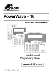
Introduction
The concept of the Alfa TCT transmission system develops the objective of previous MTA
(Mechanical Transmission Automatized) versions, i.e. to improve manual mechanical transmission
component performance. With this system, the driver does not need to press the clutch pedal or
operate the gear shift command but driving pleasure deriving from the possibility of directly controlling
the transmission is still guaranteed. Driving safety is also improved by direct control which prevents
driver errors and the incorrect control of the transmission system, allowing the driver a more advanced
interface with the vehicle.
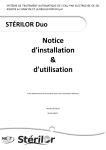
Fig. 1
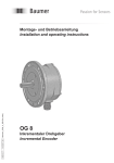
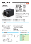
Furthermore, and here is the innovation, the TCT provides the same advantages in terms of
consumption of an MTA (Fig. 2 - horizontal axis) and the same driving comfort (Fig. 2 - vertical axis) of
an automatic gearbox. With respect to a normal gearbox, motion is transmitted from the engine to the
gearbox through two clutch plates. This allows to reduce consumption and increase driving comfort.
The system basically consists of a mechanical transmission, with two dry clutch plates and a
synchronised manual gearbox managed by an electrohydraulic robot.
Fig. 2
AT – Automatic transmission; ATnew – New-generation automatic transmission
Wet-DCT – Wet dual clutch transmission; MT – Mechanical manual transmission
MTA Selespeed – Robotised transmission; ALFA TCT – Twin clutch dry transmission
-7-
Alfa TCT
Operation overview
The TCT system for C633 has the following features:
• It improves the performance of manual mechanical transmission components.
• It saves the driver from having to operate the clutch pedal and the conventional gear lever.
• It improves driving safety by implementing a control that prevents driver errors and the
incorrect operation of the drive system.
• It is a hydraulic gearbox and clutch power assistance system that offers all the advantages
of a dry clutch and manual gearbox (weight, strength and reliability, low energy
consumption).
• It is simple to use and makes driving less tiring, especially in towns.
• It provides comfortable gear shifts, comparable to those of an automatic gearbox, by using
advanced assistance power logics.
• There is no clutch pedal in the passenger compartment and the gear shift lever is replaced
by "P (Parking) R (Reverse) N (Neutral) D (Drive)” commands on a joystick located on the
dashboard.
• Gear shifts may be suggested in automatic mode, using the lever (TIP) or the buttons (TAP).
• The gearbox may be automatically managed in "AUTO" mode.
There are two Alfa TCT transmission operating modes:
• SEMI-AUTOMATIC MODE (MANUAL): the driver manages gears shifts using the lever
located on the tunnel.
• AUTOMATIC MODE (AUTO): the electronic system manages the decision to shift gears.
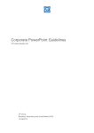
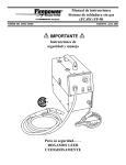
General diagram with the main components of the Alfa TCT transmission.
Fig. 3 – Application on Alfa Romeo Mito
-8-
Alfa TCT
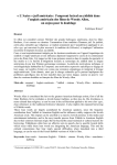
Fig. 4 – Future application on Alfa Romeo Giulietta
The power assistance system consists of an electrohydraulic unit (1) mounted directly on the gearbox
casing, which manages the following movements by means of two actuators:
• gear selection and engagement movement,
• clutch opening/closing control.
The electrohydraulic unit is controlled by five solenoid valves (which receive the required hydraulic
power from an electric pump and accumulator).
By identifying the driver's requests according to the position of the lever (3), an electronic control unit
TCU (2) autonomously manages gear shifts, by directly controlling clutches, gearbox and engine
torque; while shifting, the engine control is interlocked to gearbox control.
The synergy between gearbox and engine considerably improves system performance and saves the
driver from any need to synchronise clutch-accelerator movements while shifting. Gears may be
shifted with the accelerator pressed.
The system inhibits incorrect gear shift requests and prevents the engine from stalling or over-revving.
In terms of driving assistance, the system also ensures immediate availability of first gear when the
vehicle stops and the automatic down-shifting in the case of sudden deceleration.
The selected gear is shown on a display integrated in the instrument panel, along with indications of
faults and critical vehicle or gearbox component driving conditions. Warnings and faults are indicated
by messages and general or gearbox failure warning lights.
-9-
Alfa TCT
Alfa TCT transmission features
The new Fiat Powertrain Technologies Alfa TCT is a three-shaft transmission capable of transmitting a
maximum torque of 350 Nm. It implements innovative technology for combining the comfortable gear
shifts of an automatic transmission with lower running costs, better than that of a manual gearbox. By
increasing the transmittable torque capacity (which reaches 350 Nm), the Alfa TCT will be fitted on
various petrol and diesel B, C and D segment engines. The features of the new transmission include the
possibility of acquiring a highly sporty connotation by optimising gear shift times and uninterrupted drive
torque delivery to the wheels.
The Alfa TCT transmission is made by combining two aluminium alloy half-casings. It can be installed in
front wheel drive, transverse engine layout arrangements. The Alfa TCT has a typical three-shaft layout
for additional compactness. A particularity is that the main shaft actually consists of two mutually coaxial
driveshafts. Two dry clutches operated by two separate hydraulic actuators are used to transmit torque
to the main shaft:
•
•
a traditional one located under the gearbox casing (traditional) to manage the even gear clutch;
the second one located on the gearbox casing to manage the odd gear clutch.
Gears are engaged and the clutches are managed by an electrohydraulic robot, controlled in turn by a
specific transmission control unit (TCU). The electrohydraulic robot is positioned directly on the gearbox
casing.
- 10 -
Alfa TCT
The specific features are:
•
•
•
•
•
•
•
•
•
•
•
•
•
•
•
•
6 synchronised gears
Max. transmissible torque: 350 Nm
Three shafts, one input (main) shaft plus two layshafts (upper and lower)
Main shaft formed by two reciprocally coaxial shafts
Double dry clutch
Double hydraulic actuator for the clutches
Fixed idler manual gearbox
Synchronised reverse
Free wheel for reverse engagement
Helical tooth gears (straight teeth reverse gear)
Specific differential integrated in the gearbox casing
Brake on differential for "Parking" function
Designed for coupling to specific flywheel
Gearbox housing split in two aluminium half casings
Electrohydraulic robot for clutch and gear shift control
Dedicated TCU
- 11 -
Alfa TCT
Gearbox structure
Fig. 5
- 12 -
Alfa TCT
Fig. 6
- 13 -
Alfa TCT
Key
1.
2.
3.
4.
5.
6.
7.
8.
9.
10.
11.
12.
13.
14.
15.
16.
17.
18.
19.
20.
21.
22.
23.
24.
25.
26.
27.
28.
29.
30.
31.
32.
33.
34.
35.
36.
37.
38.
39.
40.
41.
42.
43.
44.
45.
46.
47.
48.
49.
50.
51.
52.
53.
54.
55.
56.
57.
58.
fixing screws
oil breather plug
fixing screws
complete odd gear clutch release sleeve
fixing screws
odd gear clutch release rod
main rear oil manifold
flanged nut
left differential shaft
left differential shaft oil seal
oil drain plug
gearbox casing
lower layshaft ring nut
lower secondary rear bearing inner ring
driven gear
1st speed roller cage
1st speed gear bushing
1st speed synchroniser ring
1st-3rd speed sleeve
3rd speed synchroniser ring
3rd speed driven gear
1st-3rd and 6th speed fork
3rd speed roller cage
3rd speed gear bushing
3rd speed thrust washer
6th speed spacer
6th speed sleeve
6th speed synchroniser ring
6th speed driven gear
6th speed roller cage
lower secondary front bearing circlip
lower secondary front bearing inner ring
lower layshaft
lower layshaft plug
fixing screws
upper secondary front bearing outer ring
lower secondary front bearing outer ring
primary front bearing outer ring
plate/support fixing screw and centring dowel
inner/outer main shaft seal
primary front bearing inner ring
outer main shaft
front main shaft roller cage
rear main shaft roller cage
outer main shaft thrust washer
inner main shaft front gasket
clutch release rod bushing
5th speed gear circlip
inner main shaft axial cage
5th speed driven gear
3rd speed driven gear
inner main shaft
main shaft rear bearing inner ring
parking actuator
upper layshaft rear bearing outer ring
upper layshaft rear bearing adjustment ring
main shaft rear bearing outer ring
main shaft rear bearing adjustment ring
- 14 -
Alfa TCT
59. parking ratchet
60. lower layshaft oil manifold cup
61. lower layshaft rear bearing adjustment ring
62. lower secondary rear bearing outer ring
63. rear differential bearing outer ring
64. left differential bearing adjustment ring
65. upper layshaft oil manifold cup
66. reverse idle gear roller cage
67. reverse idle gear
68. reverse shaft
69. reverse control support
70. 2nd-4th and 5th-reverse fork
71. gearbox plate
72. upper layshaft plug
73. upper layshaft
74. upper secondary front bearing inner ring
75. upper secondary front bearing circlip
76. 4th speed roller cage
77. 4th speed driven gear
78. 4th speed synchroniser ring
79. 2nd-4th speed sleeve
80. 2nd speed synchroniser ring
81. 2nd speed gear bushing
82. 2nd speed roller cage
83. 2nd speed driven gear
84. 2nd-5th speed judder thrust washer
85. 5th speed gear bushing and 5th gear roller cage
86. 5th speed driven gear
87. outer reverse synchroniser ring
88. 5th speed sleeve
89. outer 5th speed synchroniser ring
90. reverse gear bushing
91. fixed reverse gear roller cage
92. reverse gear
93. upper layshaft rear bearing inner ring
94. upper layshaft ring nut
95. rear differential bearing inner ring
96. differential gear casing
97. front differential bearing inner ring
98. cylindrical wheel
99. cylindrical ring gear fixing screws
100.
gearbox/mount centring dowel
101.
magnetic element
102.
front differential bearing outer ring
103.
clutch/CSC delivery pipe fitting clip
104.
gearbox/engine mount support
105.
fixing screws
106.
right differential shaft oil seal ring
107.
fixing screw
108.
gearbox/engine stud bolt
109.
even gear release sleeve
110.
fixing screw
111.
screw
112.
even gear clutch mechanism
113.
even gear clutch driven plate
114.
odd gear clutch mechanism
115.
thrust bearing plug
116.
pint-holder bearing
117.
screw
- 15 -
Alfa TCT
ALFA TCT operating principles - Mechanical part
FPT engineers have designed solutions to allow continuous motion transmission using the C633 manual
gearbox. Firstly, the main shaft of the Alfa TCT consists of two mutually coaxial shafts, called outer main
shaft and inner main shaft. The junction area houses an axial bearing allowing reciprocal rotation. Both
shafts are made of steel. The inner main shaft has a grooved profile for splining 3rd and 5th speed drive
gears, while the outer main shaft is made in one piece.
Section view:
1.
2.
3.
4.
5.
6.
7.
8.
9.
10.
11.
Fig. 7
3rd speed drive gear
outer main shaft (coupled to clutch K2 – even gears)
inner shaft odd gear clutch grooved profile
axial bearing
inner main shaft (coupled to clutch K1 – odd gears)
outer main shaft even gear clutch grooved profile
clutch rod bushing
outer main shaft bearing
roller cage
inner main shaft roller cage
inner main shaft hole for introducing odd gear clutch rod
The need for two main shafts derives from the fact that two pairs of gears must be meshed to allow
continuous motion gearbox. Therefore, two clutches are needed to obtain this without causing
mechanical damage, one for odd gears (called K1) and one for even gears (called K2). While travelling,
one of the two clutches is closed to transmit motion from one only pair of gears and the other clutch is
open to prevent gearbox using the other gear pair. While shifting either up or down, both clutches work in
tandem: one closes when the other one opens, and vice versa.
•
The even drive gears (2nd, 4th and 6th) are obtained on the outer shaft (coupled to clutch K2),
along with the groove for splining the even gear clutch.
•
The odd driven gears (1st, 3rd, 5th, reverse) are splined on the inner main shaft (connected to
the clutch K1), along with the grooved profile for splining the odd gear clutch.
- 16 -
Alfa TCT
Clutches
Clutch kit – view from engine side
Clutch kit – view from gearbox side
Fig. 8
The clutch kit is made by LuK and consists of a single body with two clutch plates and retaining
mechanisms of the two clutches, such as pressure plate with diaphragm springs and pressure plate
retaining springs.
The kit must be coupled to a specific flywheel which is provided with locking grooves visible on the clutch
mechanism facing outside (engine side). Disassembling the clutch kit, we can see that odd gear driven
plate K1 (normally closed) is positioned facing engine side and differs from the even gear driven plate
clutch K2 (normally open) because of the visibly smaller diameter of the main shaft splining grooved
profile. The two clutches cannot be replaced individually. The entire unit needs to be replaced in case of
problems to either clutch.
1.
2.
3.
4.
5.
6.
7.
8.
Fig. 9
odd gear clutch K1 mechanism lid
odd gear clutch K1 driven plate
odd gear clutch K1 pressure plate spring
intermediate flywheel
even gear clutch K2 pressure plate retaining spring
even gear clutch K2 pressure plate spring
even gear clutch K2 mechanism lid
even gear clutch K2 driven plate
- 17 -
Alfa TCT
Flywheel assembly exploded view - Clutch kit
Fig. 10
1.
2.
3.
4.
5.
Flywheel assembly - Clutch kit
Flywheel
Odd gear clutch K1 kit
Even gear clutch K2 plate
Clutch K2 lid-pressure plate assembly
Clutch unit section view:
Fig. 11
1.
2.
3.
4.
5.
Dual mass engine flywheel assembly
Odd gear clutch K1
Even gear clutch K2
Intermediate flywheel
Clutch K2 diaphragm spring pivot
- 18 -
Alfa TCT
Neither clutch plate K1 nor K2 (Fig. 11) is pressed on the dual mass flywheel surface. On the contrary,
they are pressed on the surface of an intermediate flywheel mass between the two plates K1 and K2 and
integral with the dual mass flywheel. The odd gear clutch K1 (engine side) operates on one side of the
intermediate flywheel mass; the even gear clutch K2 (gearbox side) works on the other side. Clutch K1 is
normally closed and provided with automatic clearance recovery mechanism. Clutch K2 is normally open
and not provided with clearance recovery mechanism. The diaphragm spring of clutch K2 has a different
layout and a different pivoting point than clutch K1: consequently, clutch K2 is normally open.
Clutch control
There are two clutch controls, usually called CSC, which work in tandem. When one clutch is released,
the other one is engaged. CSC movement is entirely controlled by the TCU which, by means of the robot
on the gearbox, can engage or release the clutches. The oil supply circuit to both CSCs is not separate
from the oil circuit used by the robot to actuate the gear engagement and selection actuators. The same
hydraulic oil is used.
1.
2.
3.
4.
5.
6.
7.
8.
Fig. 12
odd gear clutch K1 CSC
inner main shaft
outer main shaft
odd gear clutch K1 thrush bearing control rod
even gear clutch K2 CSC
even gear clutch K2 thrust plate bearing
odd gear K1 clutch thrust bearing
odd gear clutch K1 bearing plug
Functional features
The following pictures illustrate the operating features of the clutch during a normal Powershift type gear
shift.
We will take shifting from 1st gear to 2nd gear as an example. Remember that:
•
•
The 1st speed drive gear is on the inner main shaft and is connected to odd gear clutch K1.
The 2nd speed drive gear is on the outer main shaft and is connected to even gear clutch K2.
- 19 -
Alfa TCT
Travelling in 1st gear
With engine running, the system engages 1st gear when the lever is set to D.
The TCU closes the odd gear clutch K1 when starting off and for the first instants of movement.
Fig. 13
1.
2.
3.
4.
5.
6.
1st speed drive gear
2nd speed drive gear
1st speed engagement sliding sleeve
2nd speed engagement sliding sleeve
Even gear clutch K2
Odd gear clutch K1
2nd speed pre-engagement
When travelling in 1st speed, the TCU controls 2nd speed pre-engagement by means of the robot to
reduce shifting time and loss of torque caused by the gear shift.
In the picture:
The 2nd speed sliding sleeve engages but with clutch K2 open.
Fig. 14
- 20 -
Alfa TCT
Cross shifting
After pre-engaging 2nd gear, a cross shifting stage starts when the engine running conditions so require.
The TCU controls the robot so that the even gear clutch K2 is gradually closed and the odd gear clutch
K1 is gradually opened.
Fig. 15
Fig. 16
Therefore, there is a very short time (Fig. 16) during which both clutches are transmitting torque, slipping
in either 1st or 2nd gear. The cross shifting stage ends when clutch K1 is all open and clutch K2 is
definitely closed.
Fig. 17
The gear shift ends when the 1st gear sliding sleeve is released. The driver is not aware of this stage
because movement is transmitted to the wheels through clutch K2.
Fig. 18
- 21 -
Alfa TCT
Even gear CSC
The even gear CSC is a traditional hydraulic cylinder, coaxial to the gearbox main shaft. Its (annular)
piston is in contact with the even gear clutch diaphragm spring by means of the thrust bearing. The
piston is held in rest position by the reaction of the diaphragm spring. Consequently, the clutch is
normally released if there is no pressure from the robot. There is no position sensor. Position is
controlled by a pressure sensor fitted on the CSC power line. The signal is appropriately processed by
the TCU (see below).
Fig. 19
Fig. 20
- 22 -
Alfa TCT
Odd gear CSC
The odd gear CSC is all new and specific for this gearbox. The delivery oil flow from the robot causes
the movement of the piston (5) running on the guide tube. Low sliding friction is guaranteed by Teflon
runners, which also prevent jamming of the piston in the release position. The action of the piston is
transmitted by a specific rod (3) which runs inside the main shafts on a specific bushing and seal to the
thrust bearing, thus allowing to release the clutch.
When the robot stops sending pressurised oil into the CSC, the diagram spring pushes the thrust
bearing, which, by means of the control rod, positions the piston in retracted position, thus restoring
engagement conditions and making oil flow towards the reservoir. The lack of compressibility of oil
ensures gradual clutch operation because the trapped fluid column prevents the movement of the piston,
which therefore maintains its position, when the robot maintains an intermediate position. The TCU
controls the position assumed by the piston by means of a Hall effect sensor (1) fitted on the CSC to
monitor odd gear clutch release failures and prevent mechanical damage to the gearbox components.
Fig. 21
Sectioned CSC key:
1.
2.
3.
4.
5.
6.
7.
position sensor
oil inlet chamber
bearing control rod
CSC support
piston
magnet
air bleed
- 23 -
Alfa TCT
CSC and thrust bearing
Fig. 22
Fig. 23
Thrust bearing section
1.
2.
3.
4.
5.
6.
7.
odd gear clutch K1 release movement
odd gear clutch K1 engagement movement
odd gear clutch K1 CSC
odd gear K1 clutch thrust bearing
control rod
nut
thrust bearing contact ring
- 24 -
Alfa TCT
Upper layshaft
1
2
Fig. 24
1. Plastic plug
2. Upper layshaft
The upper layshaft is entirely made of steel; it is hollow so that oil can flow to the appropriate
openings for lubricating the driven gear roller bearings. A plastic plug is positioned so that the oil
channelled into the shaft can only flow out through the specific openings for lubricating the roller
bearings on the shaft inner side. The Alfa TCT upper layshaft is the same as that of the manual
gearbox. The difference concerns the position of the gears on the shaft itself. The gears interface
with the shaft by means of steel bushings.
1.
2.
3.
4.
5.
6.
7.
8.
9.
10.
11.
12.
Fig. 25
upper layshaft inner bearing
4th speed gear toothed ring
2nd speed synchroniser ring
5th speed gear
5th speed and reverse sliding sleeve
upper layshaft outer bearing
reverse driven gear
5th speed synchroniser ring
2nd speed driven gear
2nd and 4th speed sliding sleeve
4th speed driven gear
motion transfer gear from shaft to differential
- 25 -
Alfa TCT
Reverse
Motioned is reversed in the Alfa TCT by using a straight tooth idle gear installed in the gearbox and
accommodated on a specific support.
Fig. 26
1.
2.
3.
4.
Inner main shaft
Idle wheel
Idle wheel support
Reverse driven gear
- 26 -
Alfa TCT
Lower layshaft
Fig. 27
1. Plastic plug
2. Lower layshaft
The lower layshaft is entirely made of steel; it is hollow so that oil can flow to the appropriate
openings for lubricating the driven gear roller bearings. A plastic plug is positioned so that the oil
channelled into the shaft can only flow out through the specific openings for lubricating the roller
bearings on the shaft inner side. The TCT upper layshaft is the same as that of the manual gearbox.
The difference concerns the position of the gears on the shaft itself. The gears interface with the
shaft by means of steel bushings.
1.
2.
3.
4.
5.
6.
7.
8.
9.
10.
11.
Fig. 28
Motion transfer gear from shaft to differential
6th speed driven gear
6th speed sliding sleeve
3rd speed driven gear
3rd and 1st speed sliding sleeve
Lower layshaft outer bearing
1st speed toothed ring
3rd speed synchroniser ring
6th speed spacer
6th speed toothed ring
Lower layshaft inner bearing
- 27 -
Alfa TCT
Gear outlet
The gear output of the Alfa TCT is shown in the figures below.
Odd gears are shown in blue. Even gears are shown in green. The inner main shaft is light blue and the
outer main shaft is yellow.
Fig. 29 - 1st gear outlet
Fig. 30 - 2nd gear outlet
Fig. 31 - 3rd gear outlet
Fig. 32 - 4th gear outlet
- 28 -
Alfa TCT
Fig. 33 - 5th gear outlet
Fig. 34 - 6th gear outlet
Fig. 35 - Reverse outlet
- 29 -
Alfa TCT
Gear engagement rods
The robot uses four rods ending in four forks, which are engaged in the sliding sleeves for engaging
the gears.
Fig. 36
The rods are positioned in pairs. One pair engages the gear on the upper layshaft, the other pair
those on the lower layshaft. The rods are anchored to the gearbox casing by means of two hollow
steel shafts, which also allow sliding to move the sliding sleeve. The rods are shown below in gear
engagement order:
Fig. 37
- 30 -
Alfa TCT
Differential
The Alfa TCT is equipped with an open differential. The crown is joined to the body of the differential
by means of 12 screws.
Fig. 38
1.
2.
3.
4.
5.
Tapered bearing, left side
Cylindrical ring gear
"Parking" function ring gear
Differential gear casing
Tapered bearing, right side
To replicate the “Parking” function of automatic gearboxes, a toothed wheel (3 in the picture above)
is inserted on the differential body with the purpose of blocking a ratchet when the selection lever is
in the “Parking” position. The ratchet is moved mechanically by means of a Bowden cable, which in
turn moves an actuator consisting of a spring and a piston. The movement of the actuator lowers the
ratchet due to the contact with the piston.
Fig. 39
1.
2.
3.
4.
5.
Bowden engagement
Parking ratchet
Spring
Piston
Parking actuator
- 31 -
Alfa TCT
Electrohydraulic kit components
Fig. 40
The electrohydraulic kit is positioned directly on the manual gearbox. It consists of several parts: the
reservoir, the hydraulic power unit, the CSCs and the actuator unit (CAM). The unit is called Complete
Actuation System hence the acronym CAS. It comprises:
•
•
The hydraulic power unit with electric pump and accumulator;
Fig. 41
The solenoid valve actuating unit, which transforms hydraulic energy into mechanical
energy by interfacing engagement pistons and control rods. This unit is called Complete
Actuation Module (CAM).
Fig. 42
- 32 -
Alfa TCT
Power unit
The power unit supplies hydraulic energy for actuating both gear engagement/selection and clutch
CSCs. The unit includes an electric pump, high pressure pipes connecting to the solenoid valve unit and
a low-pressure, pre-shaped rubber flexible hose, which connects the valve unit to the pump.
Fig. 43
1.
2.
3.
4.
5.
precharged nitrogen accumulator
motor
oil pump
low pressure oil line
high pressure oil line
The system works with line pressure at ambient temperature in the range from 44 to 55 bar. The
engagement/release pressure thresholds are appropriately reduced at lower temperatures by effect of
the lower accumulator precharging to prevent the electric pump from overworking (because the oil is
more viscous). At higher temperatures, the engagement/release pressures are appropriately increased
to take into account the precharge increase in the accumulator. For example, the system works between
39 and 43 bar at -30°C and between 50 and 58 bar at 120°C in normal conditions. In recovery condition,
the system may reach a maximum operating pressure of 70 ± 5 bar.
The electric pump is activated when the pressure drops below 44 bar and is deactivated when the
pressure of the circuit reaches 55 bar.
Technical specifications:
•
•
•
•
•
Line pressure at ambient temperature: between 44 and 55 bar
Operating temperature: between -30°C and +120°C
Starting possible to a temperature of -30°C
Pump flow is >1.35 l/min
Accumulator volume is 480 cm3, precharged at 30 bar at 20°C
- 33 -
Alfa TCT
Complete Actuation Module
The module consists of four pressure proportional solenoid valves (PPV), a flow proportional solenoid
valves (QPV) for CSC K1, a control pressure sensor for CSC K2, a line pressure sensor, magnetoresistive sensors for controlling movements of the shifter and gear engagement pistons and gearbox
input rpm sensors.
The functions of this module are:
•
•
to control and manage clutch position
to control and manage gear selection and engagement
Fig. 44
The Complete Actuation Module includes:
1. Electrohydraulic kit line pressure sensor.
2. Proportional pressure solenoid valve PPV K2 (for even gear clutch control)
3. Proportional pressure solenoid valve PPV-S (shifter)
4. Proportional pressure solenoid valve PPV2 for engagement (engagement of first-sixthfourth-fifth speed gears)
5. Proportional flow solenoid valve QPV K1 (for odd gear clutch control)
6. Proportional pressure solenoid valve PPV1 for engagement (engagement of third - (seventh)
- second - reverse speed gears)
7. Shifter selector position sensor
8. Shifter selector axis
9. K2 CSC pressure sensor
10. K2 CSC oil outlet
11. Low pressure oil outlet towards hydraulic power unit.
12. CSC K1 oil outlet
13. Connection to pressure accumulator.
14. High pressure oil inlet from hydraulic power unit.
- 34 -
Alfa TCT
Shifter
The shifter is used to select the gears. The range selection solenoid valve PPV-S sends pressurised oil
to the selection actuator. The oil pressure moves the hydraulic spool (3) against the load of the spring
(4). Under oil pressure, the hydraulic spool goes next to the engagement actuator for the required gear.
The hydraulic spool acts as a hydraulic power shifter.
Fig. 45
1.
2.
3.
4.
Position sensor
Magnetic target on spool
Hydraulic selection spool
Load simulation spring
Hydraulic labyrinth
Fig. 46
1. Hydraulic labyrinth on the valve seat housing
2. Connections between valve seats and labyrinth ducts
3. Functional separation plate
- 35 -
Alfa TCT
Fig. 47
1. Connection between labyrinth ducts and gear engagement actuators
2. Gear engagement actuators
Gear engagement piston
Fig. 48
1.
2.
3.
4.
5.
Snap centring stop
Piston chamber plug
Steel cam
Seals
Magnetic target
- 36 -
Alfa TCT
Functional hydraulic diagram
Fig. 49
K1 - CSC odd gear clutch K1
K2 - CSC even gear clutch K2
U.I. – Hydraulic power unit – (M delivery; S exhaust)
A1 – 1st and 3rd gear engagement actuator
A2 – 6th and (7th) gear engagement actuator
A3 – 2nd and 4th engagement actuator
A4 – 5th and reverse gear engagement actuator
The electrohydraulic kit solenoid valves are of the proportional type. There are no on-off type solenoid
valves. Clutch K1 is normally closed. The clutch K1 CSC is controlled by flow proportional solenoid valve
QPV-K1. Clutch K1 is controlled by means of oil flow. Clutch K2 is normally open. The clutch K2 CSC is
controlled by pressure proportional solenoid valve PPV-K2. Clutch K2 is thus controlled by means of
action on the oil pressure towards the actuator. As shown in the mechanical description, the main shaft
consists of two parts. All even gears (1st, 3rd, 5th, R) are on one of the two parts, connected to the
clutch K1, while all the even gears (2nd, 4th, 6th) are on the other part and connected to clutch K2. The
engagement plane (range) selection is managed by the proportional pressure solenoid valve PPV-S,
which controls the shifter for hydraulic power. Gear engagement is managed by two proportional
pressure solenoid valves PPV1 and PPV2. Unlike the traditional robotised gearboxes known until today
(M20 and M40, for example), the Alfa TCT does not fit two engagement solenoid valves (e.g. an even
gear solenoid valve and an odd gear solenoid valve). The PPV1 solenoid valve controls engagement of
both the even gears and the odd gears. The same applies to the PPV2. This is how. With reference to
the hydraulic functional diagram in figure 49, we will describe engaging 1st gear and then 2nd gear. The
TCU controls PPV-S so to position the shifter in position 1. At the same time, the TCU controls solenoid
valve PPV2 to send pressurised oil along the red channel. The shifter moves to position 1, thus putting
the red channel into communication with the left part of actuator A1. At this point, oil fills the left chamber
of the actuator, shifting it rightwards and engaging 1st speed. Obviously, this happens only after the TCU
- 37 -
Alfa TCT
- through solenoid valve QPV-K1 - has opened clutch K1 by controlling the corresponding CSC. When
1st gear is engaged, the TCU releases QPV-K1 so as to drain oil from CSC-K1 and close clutch K1. The
2nd gear is pre-selected when transmitting motion in 1st gear. This is how. The TCU controls the slider
by means of PPV-S to arrange it in position 2. At the same time, the TCU controls solenoid valve PPV1
to drain pressurised oil from the blue channel. The shifter goes to position 2 and puts the light blue duct
into communication with the left side of actuator A3. In this way, pressurised oil pushes actuator A3
rightwards, engaging 2nd speed. The 2nd gear is engaged without TCU controlling solenoid valve PPVK2 because clutch K2 is already normally open. In this way, drive transmission occurs only through 1st
speed (which is engaged) and clutch K1 is closed; at the same time, 2nd speed is also engaged, but
neutralised by clutch K2 (which is open). The clutches are simply swapped when the engine operating
conditions are such to require motion transmission in 2nd gear. This is carried by gradually closing K2 by
means of PPV-K2 and opening K1 by means of QPV-K1. It is important to note that solenoid valves
PPV1, PPV2 and PPV-S are not controlled for the entire gear engagement time. The electric control to
the solenoid valves is cut off when the gear is engaged. This means, for example, that after having
engaged 1st gear, TCU stops supplying power to PPV2 to drain oil from the left of actuator A1. When oil
is drained, the TCU stop supplying power also to PPV-S* in order to be able to drain oil from the shifter.
This occurs also for the engagement of all other gears. The working channels are coloured in red and
blue on the hydraulic diagram along with the shifter ducts inside the labyrinth in the lower part of the
valve seat body (figure on page 35). The channels which connect the shifter to the actuators (A1, A2; A3,
A4) are obtained in the labyrinth arranged in the upper part of the actuator body (figures on page 36).
There is a separation plate between actuator body and labyrinth with a certain number of holes which
allow the oil to flow from a labyrinth system to the other.
Fig. 50
1. Gear engagement piston unit
2. Control dogs
* Note: After engagement, solenoid valve PPV-S is controlled to cycle the shifter along all ranges
and drain residual oil from the actuators.
- 38 -
Alfa TCT
Integrated sensor module
1.
2.
3.
4.
Fig. 51
Wire output with oil seal
Integrated sensor module
Magnetic-resistive position sensor for each engagement piston
Clutch K1 and clutch K2 rpm sensor
Integrated sensor module connector
Integrated sensor module pin-out
1 – 6th gear position signal
2 – 5th gear and reverse position signal
3 – 2nd and 4th gear position signal
4 – 1st and 3rd gear position signal
5 – Electronic GND from TCU to position sensors and temperature sensor
6 – CAS temperature signal (actuator assembly)
7 – Integrated sensor module +5 V power (6th gear position sensor and 2nd and 4th gear position
sensor)
8 – Integrated sensor module +5 V power (1st/3rd gear position sensor and 5th gear/reverse position
sensor)
9 – Odd K1 gear clutch rpm signal
10 – Electronic earth from TCU for odd gear clutch K1 rpm and even clutch K2 clutch rpm sensors
11 – Even gear clutch K2 rpm signal
12 – Integrated sensor module +5 V power (clutch K1 rpm sensor and clutch K2 rpm sensor)
- 39 -
Alfa TCT
1.
2.
3.
4.
Fig. 52
Magnetic target
Engagement actuator position sensor element
Outer main shaft rpm sensor element
Inner main shaft rpm sensor element
Sensor module position in gearbox casing
Fig. 53
Actuator position sensors (1):
• PWM output signal (0-5 V), refreshed every 0.5 ms
• 5 V ± 0.5 V power
• Working range: -30°C – 150°C
• Measuring range: 25 – 30 mm
Clutch rpm sensor (2):
• Electromagnetic, Hall effect sensor
• Output signal: square wave, width 0 – 5 V
• Max. measurable speed: 10000 rpm
- 40 -
Alfa TCT
Shifter position sensor
Fig. 54
•
•
•
•
PWM output signal (0-5 V), refreshed every 1 ms
5 V ± 0.5 V power
Working range: -30°C – 150°C
Measuring range: 25 – 30 mm
Clutch position sensor
Fig. 55
•
•
•
•
PWM output signal (0-5 V), refreshed every 1 ms
5 V ± 0.5 V power
Working range: -30°C – 120°C
Measuring range: 13 mm
- 41 -
Alfa TCT
Pressure sensors
Fig. 56
Fig. 57
•
•
•
•
Supply power: 4.5 – 5.5 V
Working range: -40°C – 135°C
Measurable pressure range: 0 – 80 bar
Electric resistance: 10 kΩ
- 42 -
Alfa TCT
Proportional flow solenoid valve
•
•
•
Fig. 58
max. flow: 11 l/min (with pressure differential of 10 bar)
control current: from 0 to 2 A (controlled directly by ECU) [from 0 to 0.8 A approx. valve
draining to reservoir; from 0.8 to 1.15 A approx. valve closing; from 1.15 to 2 A valve draining
to actuator] [see feature in Fig.]
electric resistance of winding: 2.5 Ω ± 6% at 20°C.
Proportional pressure solenoid valve
Current-pressure at 60 [°C]
65
60
55
50
45
Pressure [bar]
40
35
30
25
20
15
10
5
0
0.0 0.1 0.2 0.3 0.4 0.5 0.6 0.7 0.8 0.9 1.0 1.1 1.2 1.3 1.4 1.5 1.6 1.7 1.8 1.9 2.0 2.1 2.2
Current [A]
•
•
•
Fig. 59
max. flow: 12 l/min (with pressure differential of 10 bar).
control current: from 0 to 2.2 A (controlled directly by ECU).
electric resistance of winding: 2.6 Ω ± 6% at 20°C.
- 43 -
Alfa TCT
General system concepts
• Gear position on grid and solenoid activation
• The notion of "kiss point" and explanation of the existence of two kiss points related to two
clutches
• Wake-up (SDU presence indication)
• Overspeed and underspeed gear shifts
• Gearbox limp home and engine limp home, special automatic (even gear only or odd gear only
engagement strategies)
• Retry
• Powerlatch
• Description of powershift and gear shifts with torque interruption strategies
• Description of creeping
• Description of torque tracking and speed tracking
Gear positions on grid and solenoid valve activation:
Fig. 60
A.
B.
C.
D.
Travel
Sensor reading
EV Shifter current
Engagement sensor reading
The coloured areas represent the reading value of the gear engagement sensor:
• For 3rd, 6th, 4th, 5th gears, the sensor reading value is high.
• For the other gears (i.e. 1st, 2nd, reverse and possibly 7th), the sensor reading value is low.
• 1st gear is engaged using PPV2 and 2nd gear is engaged using PPV1 to allow engagement of
one of the two start-off gears if either engagement valve is faulty.
- 44 -
Alfa TCT
The considered features of the selection actuator are:
•
•
•
•
•
•
•
•
•
selection travel 1st-3rd: 0 mm
selection travel 2nd-4th: 18 mm
selection stroke reverse-5th: 27 mm
selection stroke 6th: 9 mm
piston diameter: 10 mm
3
max. chamber volume: 2.12 cm
2
thrust area: 0.79 cm
spring pre-load: 58.9 N
spring stiffness: 5.3 N/mm
Fig. 61
Kiss point
The kiss point is calculated after the engine has been started. It is the point in which a clutch
starts/stops transmitting torque.
A distinction is necessary:
•
Clutch K1: the respective CSC is provided with position sensor, and therefore the kiss
point is actually identified by a distance measurement. Similarly, as in robotised gearbox
applications, the kiss point position is identified by the distance (kiss delta) from the
closed clutch position. In order to learn this position, the clutch opens when the engine is
started and the clutch starts closing when the engine rpm curve exceeds a set threshold.
The kiss point is detected and the delta kiss is thus calculated.
•
Clutch K2: CSC is not equipped with a position sensor and its position is inferred by
reading the pressure sensor located on the feeding pipe instead. The kiss point is
therefore identified by a pressure value instead of a position delta. This value is normally
in the range from 3 to 5 bar when the system is new.
The K1 kiss point is normally learnt only after having started the vehicle with the gearbox in neutral.
On the other hand, the K2 kiss point may be learnt with the 1st gear engaged because the clutch is
normally open, providing that the K1 kiss point has already been determined.
Wake-up
This system function allows pressure from the hydraulic circuit to escape before key-on when the door
is opened.
The TCU is woken up when the door is opened and the pump is activated if the pressure in the
hydraulic circuit is too low.
The pump will not start up if the pressure in the circuit is adequate (the pressure must be under the
pump pressure threshold level for the pump to be activated) or may be due to a fault (e.g. failed
operation of a door switch, a faulty relay or pump fuse, etc.).
- 45 -
Alfa TCT
SDU (Smart Driver Unit)
With respect to applications with MTA robotised gearbox, electric power supply is only sent to the
pump through a device named SDU according to a given law (not in ON/OFF mode) in order to
reduce pump noise.
Fig. 62
Fig. 63
SDU pin-out
1 – Electrohydraulic unit pump motor power (+)
2 – SDU power (+ 12 V battery)
3 – Diagnosis feedback for TCU control unit
4 – SDU PWM command from TCU control unit
5 – Electrohydraulic unit pump motor earth (-)
6 – SDU earth (body earth)
- 46 -
Alfa TCT
14
12
(Volt)
10
8
6
4
2
0
0
10
20
30
40
50
60
Duty-Cycle (%)
70
80
90
100
Fig. 64
Horizontal axis - PWM command from TCU control unit
Vertical axis - pump motor supply voltage output from SDU control unit
The SDU receives in input (pin 4, see pin-out) a PWM command from TCU. According to the PWM
command duty-cycle, the SDU activates the electrohydraulic pump motor according to a law shown in
the graph in Fig. 64. The graph shows the TCU command duty-cycle on the horizontal axis and the
voltage sent by SDU to electrohydraulic unit pump motor on the vertical axis.
Specifically:
Duty-cycle from 0% to 5%: switch from 0 V to 13 V (saturation) – switch from off to on.
Duty-cycle from 5% to 20%: 13 V constant power – maximum pump speed.
Duty-cycle from 20% to 30%: pump power switch from 13 V (saturation) to regulation voltage – switch
from maximum pump speed to medium pump speed.
Duty-cycle from 30% to 75%: pump motor running at average voltage – average pump speed is
maintained.
Duty-cycle from 75% to 85%: pump motor power voltage switch from average value to zero (0 V) - the
pump motor is still on in this range.
Duty-cycle from 85% to 95%: pump motor is stopped.
The typical noise of MTA robotised gearboxes, usually heard when the driver's door is opened, has been
eliminated as a result of this power law governing the pump motor.
- 47 -
Alfa TCT
Underspeed gear shifts
An underspeed gear shift occurs when the TCT (in manual mode) automatically shifts down one or
more gears (e.g. from 5th to 4th to 3rd) to prevent engine underspeed and stalling. As a result, the
vehicle can decelerate without requesting to shift down, because the system shifts down and
ultimately engages 1st gear when the vehicle is stationary.
Limp home
Limp home is low-performance mode used in presence of a system failure. Only 1st, 2nd and 3rd gear
and reverse can be engaged in this mode which can be used for some faults only. System
performance in limp home conditions is obviously worse than normal (gear shifts are slower). Engine
limp home can be requested in some cases. This mode limits engine rpm.
Special automatic maps may be activated in some recovery conditions (automatic even gear strategy
and automatic odd gear strategy). The objective is to be able to drive the vehicle while cutting out the
faulty gearbox part.
Retry
The retry strategy attempts to engage a gear which, having been previously requested, was not
engaged because of a problem. After recognising that gear engagement is impossible, the system
attempts to engage the gear again (starting from neutral). It tries twice more if the second attempt
fails. Neutral is engaged if all attempts fail.
The distinction explained below is needed to understand how the system works after the third failed
engagement attempt:
•
Powershift: the shifting operation has not been completed and therefore the previous
gear is still engaged and the corresponding clutch is still transmitting torque. The driver is
unaware of problem because traction is maintained. Another set of three attempts can be made, if
a new gear shift is required. If this behaviour is systematic, after a given series of consecutive
events, the gearbox part of the gear concerned by the failure is cut out by and appropriate
recovery strategies are implemented (automatic even or odd gear strategy).
•
Gears shifts with torque interruption: ISO MTA management logic will be applied,
i.e. the system will attempt to engage the highest gear compatible with speed.
There are special cases:
the gearbox will be placed in neutral if retry fails when 1st gear is requested and the
vehicle is stationary
the gearbox will be placed in neutral if retry fails when reverse is requested and the
vehicle is stationary
Power latch
Power latch is the TCU shut-down procedure. This procedure starts at key-off (+15 off) if certain
conditions are present:
No gear shift in progress
Engine speed below 400 rpm
Clutch speed equal to 0
Clutch K1 closed
Key signal + 15 at 0.
- 48 -
Alfa TCT
The shut-down procedure starts one second after "K15 off" if these conditions are present. During this
procedure, the TCU is self-powered at +30 (see pin-out) and saves a number of parameters (clutch
adjustment parameters, system counters, such as gear engagement counters, etc.) in the flash
memory.
The power latch procedure cannot be run (TCU will shut down at +15 off) if +30 TCU power is not
present.
The power latch procedure lasts about 5 seconds.
Description of powershift and gear shifts with torque interruption strategies
In Powershift mode there is no interruption of torque transmission to drive wheels during the gear shift
(see cross-shifting clutch logic described on pages 20 and 21). Alfa TCT normally shifts all gears in
this manner, but there are some exceptions in which an interrupted torque shifting method is used.
These are:
•
•
Multiple gear shifts concerning the same clutch
Activation of recovery procedures required for safety reasons
Interrupted torque gear shifts are made according to a logic already implemented on robotised MTA
transmissions, i.e.:
1.
2.
3.
4.
both clutches are opened
the engaged gear is released
a new gear is engaged
only the clutch of the engaged gear is closed
Description of creeping
On vehicles with transmission and torque converter, creeping mode which allows the vehicle to
advance in D or R simply by releasing the brake. This behaviour is intrinsic.
On vehicles equipped with Alfa TCT, this function is obtained by releasing the brake and engaging a
gear. Clutch K1 is slightly closed enough to allow the forward/backward movement of the vehicle. This
function is extremely useful while parking or moving forward in a queue at a very slow speed.
Description of torque tracking and speed tracking
•
As known, clutch K2 is normally open. The hydraulic unit must keep oil pressurised in the
corresponding CSC to close clutch K2 when an even gear is engaged. Due to its construction,
the Belleville cup spring of clutch K2 cannot be pressed at loads higher than a given value.
The torque tracking strategy obtains this objective by closing K2 and applying a
transmissibility margin with respect to the currently transmitted engine torque. For example, if
the engine is transmitting 100 Nm (information received from ECU through CAN), the clutch is
closed so that 120 Nm can be transmitted (with a transmissibility margin of 20 Nm).
•
We will now consider the case of the vehicle is moving forward with an odd gear and no even
gear engaged. Because clutch K2 is normally open, the respective gearbox part will stop
turning. The speed tracking strategy is applied by slightly closing the clutch K2 to keep it
turning.
- 49 -
Alfa TCT
Operating logics
Hydraulic circuit pressurisation
When the pressure is under the minimum operating threshold, the hydraulic circuit is pressurised in
two different ways:
•
•
when the driver's door is opened, the system automatically pressurises the hydraulic system
to allow, if requested, a gear shift without needing to wait for the hydraulic circuit to be
charged (fixed pump activation timing)
at key-on: the system ECU is powered (and will remain powered until the key is turned off and
the vehicle and engine speed is zero).
The
electric
pump
is
also
powered
to
when the minimum pressure (approximately 44 bar) is reached.
pressurise
the
unit
When the driver turns the key to the unstable cranking position, TCU allows to crank the engine if the
lever is at P or N:
Cranking/starting off
The engine ECU directly controls the starter relay to start the engine when the ignition key is turned
and after receiving an authorisation from the TCU.
Operation with engine off
The available gears with the engine off are Reverse, 1st and N.
Setting off
The engageable gears, with the engine on and the vehicle stationary, for setting off are:
•
1st and R; these gears in these conditions can be requested only by moving the lever.
The vehicle only sets off if the driver presses the accelerator pedal (releasing the brake pedal); at this
point, the system gradually engages clutch K1 to set off. The driver can control the torque transmitted
by clutch K1 by modulating the position of the accelerator pedal; when the accelerator is released,
clutch K1 must gradually release when a minimum engine rpm is reached. When the system detects
synchronisation between the engine and clutch rpm, it completes engaging the clutch (fully closed). A
special clutch engagement map is implemented for each of the two gears used for setting off. When
setting off, shift up may be requested if rpm is equal to engine rpm.
Setting off in 2nd gear is possible when the vehicle is moving slowly.
Automatic clutch engagement downhill with accelerator pedal released
If the vehicle picks up speed when travelling downhill with gear engaged and accelerator released, the
clutch is automatically closed when a pre-set speed is reached to supply engine brake function. If the
driver presses the accelerator pedal, the torque transmitted is once again controlled directly by the
driver. Automatic clutch engagement is interrupted if the vehicle moves in the opposite direction to the
engaged gear.
- 50 -
Alfa TCT
Deceleration
When decelerating, e.g. with gear engaged and accelerator pedal released, the system automatically
releases the clutch to prevent engine stalling when approach idling speed. The release occurs at an
engine speed which depends on the deceleration level and driver's controls (brake pressed or not).
However, the gearbox automatically shifts down if a gear higher than 2nd gear is engaged during
deceleration. 1st gear is automatically engaged when the vehicle stops.
Gear shift using lever (semi-automatic operating mode)
When the vehicle is moving and the clutch is completely engaged, an up or down request from the
driver by means of the gear control lever will cause a gear shift. The requests are accepted by the
system only if they are compatible with engine under-revving and over-revving limits. As a rule,
operating the lever causes to shift only one gear up or down. In some operating conditions, however,
more than one gear can be shifted by quickly double-tapping the control. The gear can be shifted up
by the driver without releasing the accelerator pedal. Once the control is accepted by the system, an
automatic sequence of steps is run to follow the driver's behaviour.
A gear shift may be interrupted at any time by another request from the driver providing the second
request is acceptable (that is, compatible with engine under-revving and over-revving limits).
Automatic gear shift (auto mode)
The Alfa TCT is equipped with an automatic operating mode, very similar to that of a conventional
automatic transmission. The gear to be engaged is selected using a (double) map which correlates
the power required by the driver and the car speed. A double map is needed because two
AUTOMATIC control modes named Normal & Dynamic can be selected by pressing a button in the
dashboard. If the accelerator pedal is released in Dynamic mode, the system does not shift up to
maintain engine brake function. In Normal mode, instead, the gear is shifted up (if allowed) when the
accelerator is released to the benefit of consumptions. The gear shift mode is identical to that of semiautomatic operation using the lever but transmission and engine actuator control parameters
dedicated to each mode are used. Automatic mode is selected by tipping the lever to the
corresponding toggle position. It is turned off in the same way.
N.B.: the system switches to AUTOMATIC if the lever is faulty.
Neutral request
This request takes priority over all the other requests and is possible using the lever only. As
mentioned, the brake pedal must be pressed when the engine is off. Neutral request is always
accepted when the vehicle is moving.
Information for the driver (display and buzzer)
The system informs the driver by means of:
•
•
display: "Manual" mode operation and gear engaged, "D" operation and gear engaged,
system failure
buzzer: vehicle misuse, unsafe conditions, system failure.
Some examples of misuse are listed below:
•
setting off with overheated clutch
if the system is shut down with gearbox in neutral, the buzzer must indicate the danger of leaving the
engine off without having engaged a gear.
- 51 -
Alfa TCT
Self-calibrations
Clutch bleeding procedure
The guidelines of the procedure are illustrated below:
When?
•
After CAM (Complete Actuation Module) repairs, after replacing hydraulic components (valves,
pump, pressure sensor, delivery pipe, etc.) or generic CAM intervention.
•
For filling after draining needed for CAM repairs.
Why?
The objective of this self-calibration procedure is to eliminate air from the hydraulic circuit after replacing
one of the aforesaid components. A customisable number of clutch K1 and K2 opening/closing cycles is
run with the electric pump on.
What tools are needed?
Examiner diagnosis instrument
NOTES:
The procedure takes approximately 1 minute.
Power latch takes approximately 15 seconds.
The procedure must be run in the following conditions:
- key on
- engine off (not stopped by S&S)
- lever at parking
- clutch K1 position sensor OK
- clutch K1 actuator OK
- clutch K2 pressure sensor OK
- clutch K2 actuator OK
The procedure will end without indicating an error code if any one of the conditions listed above does not
occur.
- 52 -
Alfa TCT
Accumulator depressurisation
The guidelines of the procedure are illustrated below:
When?
Before CAM (Complete Actuation Module) repairs for replacing hydraulic components (valves, pressure
sensor, delivery pipe, gearbox-hydraulic kit separation, etc.) or generic CAM interventions.
Why?
The objective of this self-calibration procedure is to drain the hydraulic circuit, by sending CAM oil to the
reservoir to allow replacement of the aforesaid components. It consists in running a customisable
number of clutch K1 and K2 opening/closing cycles with the electric pump off.
To check oil level.
What tools are needed?
Examiner diagnosis instrument
NOTES:
The procedure takes approximately 1 minute.
Power latch takes approximately 15 seconds.
Check (read hydraulic pressure) that the pressure in the hydraulic circuit is under the accumulator precharge threshold (approx. 2-3 bar).
The procedure must be run in the following conditions:
•
•
•
•
•
•
•
key on
engine off (not stopped by S&S)
lever at parking
clutch K1 position sensor OK
clutch K1 actuator OK
clutch K2 pressure sensor OK
clutch K2 actuator OK
The procedure will end with self-calibration KO if any one of the conditions listed above does not occur.
- 53 -
Alfa TCT
Clutch self-calibration enabling
The guidelines of the procedure are illustrated below:
When?
•
•
•
•
•
•
At vehicle end of line
After replacing ECU during Service
After replacing/removing gearbox
After replacing/removing (disconnecting) CAM
After replacing clutch pack
After replacing clutch sensors
Important: Run the “Data Set Deletion” before running the self-calibration procedure described here if a
component is replaced.
Why?
The objective of the procedure is to quickly recalculate the kiss point, i.e. the point in which the clutches
start transmitting torque.
What tools are needed?
Examiner diagnosis instrument
NOTES:
The procedure takes approximately 1 minute.
Power latch takes approximately 15 seconds.
The procedure must be requested before starting the engine, with key-on and gearbox in neutral. The
engine can then be started.
The procedure can also be requested after starting the engine providing the gearbox is in neutral. If the
gearbox is not in neutral, the request remains pending until neutral is engaged (see below)
Wait for the TCU to end testing the two clutches before key-off.
The procedure can start in the following conditions:
-
key on
engine on
lever at parking
no gear shift in progress
engine running
The instrument will hang until at least one of the previous conditions occurs. The procedure will be run
as soon as the aforesaid conditions occur.
The following conditions are monitored during the procedure:
-
key on
transmission in neutral
clutch K1 position sensor OK
clutch K2 pressure sensor OK
engagement actuators OK
sensor/actuator/ECU power supply OK
The procedure will be aborted (self-calibration KO) if even only one of these conditions is not true.
Examiner cannot request to interrupt the procedure. It will be concluded after having been started.
- 54 -
Alfa TCT
End-of-line service self-calibration
The guidelines of the procedure are illustrated below:
When?
•
•
•
•
•
At end of line (when necessary)
After replacing the transmission
After replacing/disconnecting CAM
After replacing any selection or engagement sensor
After replacing the TCU
Important: Run the “Data Set Deletion” before running the procedure described here if a component is
replaced.
Why?
The objective of the procedure is to store the gear shift grid thresholds.
What tools are needed?
Examiner diagnosis instrument
NOTES:
The procedure takes approximately 1 minute.
The procedure must be requested with engine off and key on.
Hydraulic pressure must be above the gear shift acceptability threshold (42÷51 bar range).
Battery voltage must be within the set limits (vehicle operating range).
Turn key-off and complete power latch (15 sec) to store values in TCU.
Power latch takes approximately 15 seconds.
The following functions must be automatically activated for the procedure:
•
•
•
•
•
•
•
Clutch K1 closed position quick self-calibration
Clutch bleeding
EV clutch K1 current self-calibration
Clutch K1 travel test
K2 current characterisation test
Shifter calibration (position and current calculation)
Engagement grid self-calibration
The procedure must be run in the following conditions:
• engine off (not stopped by S&S)
• lever at parking
• battery voltage in a range
• K15 on
• hydraulic pressure over threshold
The procedure will end with self-calibration KO if any one of the conditions listed above does not occur.
Furthermore, the procedure may be aborted for the following reasons:
-
engagement, selection, clutch sensor error
selection, engagement driver/solenoid valve, clutch error
sensor/actuator/TCU power supply error
- 55 -
Alfa TCT
New actuators
The guidelines of the procedure are illustrated below:
When?
•
•
After replacing CAM
After replacing clutch selection and/or engagement solenoid valve
Why?
The objective of the procedure is to force the solenoid valve offset values to those of new solenoid
valves.
What tools are needed?
Examiner diagnosis instrument
NOTES:
The procedure takes approximately 5 seconds.
Power latch takes approximately 15 seconds.
- key on
- engine off (not stopped by S&S)
The procedure must be requested with engine off and key on.
Turn key-off and complete power latch to store values in TCU.
- 56 -
Alfa TCT
Data Set Deletion
The guidelines of the procedure are illustrated below:
When?
•
•
•
•
•
•
•
•
•
•
Replacing the hydraulic kit
Replacing the transmission
Replacing the clutch pack
Replacing the sensor module
Replacing the pump
Replacing the accumulator only
Replacing SDU
Replacing clutch K1 position sensor
Replacing K2 pressure sensor
Resetting statistic data
Important: The "Data Set Deletion" procedure must be carried out after the "Historical Data" rewriting
procedure if the TCU is replaced at the same time as one of the components listed above.
Why?
Failure to run the procedure will not effect system operation.
The following counters describe the history of each single part. This is why the associated data must be
reset or set to default values when one of the aforesaid components is replaced. Furthermore, the
following counters can be used to identify the number of incorrect manoeuvres or conditions of the
system when an error was validated.
What tools are needed?
Examiner diagnosis instrument
- 57 -
Alfa TCT
Gear engagement procedure
This Active Diagnostic procedure is used to engage all gears with the vehicle stationary. The procedure
must be used to diagnose problems concerning the solenoid valves.
The procedure engages all the gears. Steps include centring neutral, keeping both clutches open,
operating the shifter, appropriately controlling the engagement valve and switching back to neutral.
NOTES:
The procedure must be run in the following conditions:
- key on
- engine off (not stopped by S&S)
- gear lever in N
Longitudinal accelerator sensor learning procedure
The guidelines of the procedure are illustrated below:
When?
•
•
•
End of line
After replacing the gearbox ECU
After replacing the longitudinal accelerator sensor
Important: Run the “Data Set Deletion” before running the procedure described here if a component is
replaced.
Why?
The following procedure is used to learn the longitudinal acceleration offset transmitted by NYL (yaw
sensor node).
Failure to perform the procedure will affects system operation. For this reason, if must be carried out at
end of line and during service.
What tools are needed?
Examiner diagnosis instrument
Conditions:
key on
engine off
vehicle on level ground
- 58 -
Alfa TCT
"HISTORICAL DATA" rewriting procedure
The guidelines of the procedure are illustrated below:
When?
This procedure must only be run after replacing the TCU.
Why?
Failure to run the procedure will not effect system operation.
This procedure is used to save the system history records (transmission and CAM) for transferring data
from one TCU to another.
This operation is possible if the services necessary for running it are not affected. In other words, the
procedure cannot be run if the data cannot be read from the TCU to be replaced. As mentioned, in this
case the system operation is not affected.
If the TCU and any other component subject to the "Data Set Deletion" procedure are replaced at the
same time, the historical data of the component to be replaced must be deleted before copying the
records.
What tools are needed?
Examiner diagnosis instrument
- 59 -
Alfa TCT
Kiss Point learning and clutch gearbox curve fine-tuning procedure
The following two cases may occur with regards to the on-vehicle kiss point and transmission curve finetuning learning procedures:
•
•
Cases in which both kiss point and transmission curve fine-tuning learning procedures must be
run
Cases in which only the kiss point learning procedure must be run
The cases are illustrated in the following table:
Cases in which both kiss point and
transmission curve fine-tuning learning
procedures must be run
When replacing the TCU (for 955 application
(Mito) only, remember than in this case the
longitudinal accelerometer offset procedure must
also be run)
Cases in which only the kiss point
learning procedure must be run
When hydraulic unit is replaced
When replacing the gearbox
When replacing the sensor module
When replacing clutch K1 or K2 CSC or both
CSCs
When replacing clutch K2 pressure
sensor
When replacing the clutch pack
Whenever the following "Data Set Deletion"
functions are started in TCU even without having
replaced the corresponding component:
• Gearbox replacement
• Clutch unit replacement
• Clutch K1 position sensor replacement
• Statistic data reset
Starting the clutch parameter reset service (DATA SET DELETION) which resets the following
parameters:
Clutch pack replacement data
Self-calibrated clutch closed position
All closed even clutch pressure
Self-calibrated clutch slip starting position delta (PIS)
Even clutch calculated pressure
Odd clutch plate temperature (maximum between temperatures of surfaces S1 and
S2)
Even clutch plate temperature (maximum between temperatures of surfaces S1 and
S2)
Clutch K1 transmissibility index
Clutch K2 transmissibility index
Clutch K1 overheat permanence time
Clutch K2 overheat permanence time
Self-calibrated kiss point K1
Self-calibrated kiss point K2
Clutch K1 closed position
Clutch K2 feature
Shifter OK calibration
Launch Control counter
- 60 -
Alfa TCT
The warning light will be on and two errors will be present:
•
•
End-of-line service self-calibration procedure error (P290D)
Not calibrated kiss points error (P290E)
The “END-OF-LINE/SERVICE SELF-CALIBRATION” and “CLUTCH SELF-CALIBRATION ENABLING”
functions must be started in the order shown below to resume correct system operations.
Kiss point and transmissibility curve fine-tuning learning procedure operating flows
START
START
“END-OF-LINE
SERVICE
SELFCALIBRATION" function with
engine off and lever in P
ANALYSE AND SOLVE
CAUSE OF PROBLEM
ACCORDING TO
INDICATED FAULT
NO
RESULT OK?
YES
Key-off, power latch
and key-on
CHECK TEMPERATURE OF
CLUTCH K1 AND K2
NO
RUN CLUTCH WARM-UP
PROCEDURE
TEMPERATURE > 40°C?
YES
Continue the procedure on
next page
- 61 -
Alfa TCT
START FUNCTION
“CLUTCH SELF-CALIBRATION
ENABLING” procedure with engine
off OFF, transmission in neutral and
lever at P
ANALYSE AND SOLVE CAUSE OF
PROBLEM ACCORDING TO
INDICATED FAULT
Start engine
NO
RESULT OK?
YES
Key-off, power latch and
key-on
RUN TRANSMISSIBILITY FINETUNING PROCEDURE
DELETE ERRORS
END
- 62 -
Alfa TCT
Kiss point learning procedure operating flow
START
START
“END-OF-LINE
SERVICE
SELFCALIBRATION" function with
engine off and lever in P
ANALYSE AND SOLVE
CAUSE OF PROBLEM
ACCORDING TO
INDICATED FAULT
NO
RESULT OK?
YES
Key-off, power latch
and key-on
CHECK TEMPERATURE OF
CLUTCH K1 AND K2
NO
RUN CLUTCH WARM-UP
PROCEDURE
TEMPERATURE > 40°C?
YES
Continue the procedure on
next page
- 63 -
Alfa TCT
START FUNCTION
“CLUTCH SELF-CALIBRATION
ENABLING” procedure with engine
OFF, transmission in neutral and
lever at P
ANALYSE AND SOLVE CAUSE OF
PROBLEM ACCORDING TO
INDICATED FAULT
Start engine
NO
RESULT OK?
YES
Key-off, power latch and
key-on
DELETE ERRORS
END
- 64 -
Alfa TCT
CLUTCH HEATING PROCEDURE
Check clutch temperatures ("Odd clutch plate temperatures" and "Even clutch plate temperatures,
respectively).
Run the following procedure if these temperatures are lower than 40°C:
1.
2.
3.
4.
Select manual mode.
Engage 1st gear and set off in 1st gear with pedal in middle/low position.
After reaching a sufficient engine rpm, shift to 2nd gear.
Drive for a short distance to make sure that the even gear clutch is closed, then slow down until
almost reaching the automatic shift-down threshold, then press the accelerator (pedal in
middle/low position) to set off in 2nd gear. This will cause the K2 clutch to slip and heat it up.
5. Check K1 and K2 clutch temperatures again. If at least one is lower than 40°C, repeat the
procedure from point 2; otherwise proceed according to the sequence shown in the flow chart.
TRANSMISSIBILITY CURVE FINE-TUNING PROCEDURE
Wait for the engine to warm up before starting the procedure: engine water temperature higher than
90°C (an empiric indication is to wait for the cooling fan to start up for the first time).
1.
2.
3.
4.
Select manual mode.
Engage 1st gear and set off in 1st gear with pedal in middle position.
After reaching a sufficient engine rpm, shift to 2nd gear.
Drive for a short distance to make sure that the even gear clutch is closed, then slow down until
almost reaching the automatic shift-down threshold, then press the accelerator (pedal in middle
position) to set off in 2nd gear.
5. Engage 1st gear and set off with the pedal in middle-high position.
6. After reaching a sufficient engine rpm, shift to 2nd gear.
7. Drive for a short distance to make sure that the even gear clutch is closed, then slow down until
almost reaching the automatic shift-down threshold, then press the accelerator (pedal in middlehigh position) to set off in 2nd gear.
8. Engage 1st gear and set off in 1st gear with pedal in low position.
9. After reaching a sufficient engine rpm, shift to 2nd gear.
10. Drive for a short distance to make sure that the even gear clutch is closed, then slow down until
reaching the automatic shift-down threshold, then press the accelerator (pedal in low position) to
set off in 2nd gear.
11. Select automatic mode.
12. Drive about 5 km, possibly on a mixed urban/extra-urban route, shifting gears in different
accelerator pedal conditions.
The transmissibility curve self-learning procedure must be run during a dynamic test because the TCU
must fine-tune the transmissibility curve in its memory according to the features of the new clutch unit (if
the latter was replaced and is therefore new). If the TCU is replaced, the latter will store a standard
transmissibility (default) curve which must be fine-tuned according to the features of the clutch unit (which
is already present on the gearbox and not replaced). The self-learning procedure must be run also when
a component which interfaces with the clutch pack is replaced (CSC K1 or CSC K2; gearbox).
- 65 -
Alfa TCT
Procedure summary.
1) Clutch bleeding procedure
The objective of this self-calibration procedure is to eliminate air from the hydraulic circuit after
replacing/repairing one of the CAM components. A customisable number of clutch K1 opening/closing
cycles is run with the electric pump on.
2) Accumulator depressurisation procedure
The objective of this procedure is to drain the hydraulic circuit, sending CAM oil to the reservoir to allow
replacement of the CAM components. It consists in running a customisable number of clutch K1
opening/closing cycles with the electric pump off.
3) Clutch self-calibration enabling procedure
The objective of this procedure is to autonomously calculate the kiss point for clutches K1 and K2.
4) End-of-line Service self-calibration procedure
The objective of this procedure is to automatically calculate the engagement and selection thresholds.
5) New actuator procedure
The objective of this procedure is to write the solenoid valve leakage value in ROM.
6) Data Set Deletion procedure
The objective of this procedure is to clear gearbox or CAM component data for replacement.
7) Gear engagement procedure
The objective of the procedure is to engage the required gears using the FIAT protocol.
8) Longitudinal acceleration sensor learning
The objective of the routine is to calculate and store the longitudinal acceleration value.
9) “HISTORICAL DATA” rewriting procedure
The objective of the procedure is to rewrite system data records for TCU replacement.
10) Clutch transmissibility index self-learning
The objective of the transmissibility index learning procedure is to model the TCU transmissibility curve
according to the features of the clutches.
- 66 -
Alfa TCT
Functional interaction with other systems
Interaction with engine control
The two systems do not interact while travelling, because the system has no task to perform.
Therefore, data and signals are only exchanged on the network.
Unlike robotised gearbox, when setting off or shifting TCU is master with respect to the engine control
unit, and therefore cuts out all the safety conditions that are always managed by the engine. The
engine is managed only by the TCU. This control ends after setting off or shifting.
With the introduction of S&S operating logics, further information is exchanged between the
transmission and engine control units. All the possible cases are described below. To understand
what occurs, we will consider the example of a driver approaching a red light:
•
•
•
•
•
•
The engine stops when the car stops (the driver is pressing the brake pedal).
As soon as the driver releases the brake pedal:
ECU asks TCU to set the transmission in neutral.
Once the transmission is in neutral, TCU informs ECU that the transmission is secured.
ECU can restart the engine.
ECU restarts the engine and at the same time asks TCU to engage the previously released
gear.
Interaction with Cruise Control
The CC system is not affected by the presence of the TCT system. There is no function interaction logic
with the system.
Safety and functions in case of failure
These strategies manage incorrect commands to prevent potentially dangerous situations or critical
conditions for the transmission or the vehicle.
Key lock
Two situations can occur after stopping the engine:
•
•
The driver positions the lever in P
The driver positions the lever a position other than P
In the first case, the driver can remove the key from the dashboard without any problem; in the
second case, the key cannot be removed because the vehicle is not safe. The following operations
are possible:
•
•
The driver turns the key again and positions the lever in P
Despite knowing that vehicle conditions are not safe, the driver removes the ignition key
manually, using the mechanical release control.
Obviously, the second option may only be used in genuinely critical cases.
- 67 -
Alfa TCT
P-R-N-D LEVER OPERATION
Fig. 64
P-R-N-D lever configuration
Fig. 65
•
Backlit fretting fixed at +key
•
Steering wheel paddles (opt)
Lever connector pin-out
Pin
1
2
3
4
5
6
7
8
9
10
11
12
Description
+30 direct battery power
+15 key-operation power
Earth
D Tip position signal to TCU (A21)
Parking Lock signal to TCU (A8)
Key lock signal
CCAN H (in)
CCAN H (out)
CCAN L (in)
CCAN L (out)
Steering wheel controls earth signal
Steering wheel controls earth signal
- 68 -
Alfa TCT
Engine off and vehicle stationary
Door open
With the vehicle stationary, the instrument panel is turned on when the door is opened and various
vehicle-related information is displayed. The engaged gear is however not displayed.
The electric pump of the hydraulic unit is activated to pressurise the circuit and allow the system to be
activated when starting is requested.
Measures before key-on
At key-off
(vehicle stationary with key-operated power off):
•
if the lever is at P: the gear lever cannot be moved neither with the brake pedal released, nor
with the brake pedal pressed, nor by pressing the lever lock button on the knob (nothing is
displayed)
•
if the lever is at R/N/D/TIP: the gear lever can be moved to position P (by pressing the button on
the knob), after which the lever is mechanically locked in P (see previous case).
TCT stops communicating on CAN at the key-off (the vehicle is stationary).
The gear lever engages the parking lock and displays P position only if the lever is moved to P within 5
seconds from key-on Æ key-off
After 5 seconds, the parking lock can be engaged, but the indication will not appear on the display.
Alfa TCT keeps the gear prior to key-off engaged; at the following key-on the gear selected by the lever
position is displayed.
Key on (+15)
The icon on the gearbox trim corresponding to the lever position lights up.
When the lever is faulty, all the icons are lit and blink. With the vehicle stationary and key on (keyoperated power on), the instrument panel must display the gear selected by the lever position.
Operating logics (Dynamic, Normal and All Weather) of this application are managed by the Body
Computer using a specific signal. All the logics can be set using the "lever", both in Automatic and
Manual conditions.
Shift lock
When the car is stationary, the lever can only be shifted from position P (corresponding to neutral) when
the brake pedal and knob button are pressed.
Shifting the lever
All shifts must be performed exclusively with car stationary and engine idling.
The drive wheels are mechanically locked in position P.
•
Shifting from PÆR is only allowed with the brake pedal pressed and the lever button pressed.
•
Shifting from R Æ N is free.
•
Shifting from N Æ D is free.
•
Shifting from D Æ Tip is free.
•
Shifting from Tip Æ D is free.
•
Shifting from D Æ N is free.
•
The lever button must be pressed to shift from N to R.
•
Shifting from R Æ P is possible with the gear lever button pressed.
- 69 -
Alfa TCT
Lever initial position
These shifts are summarised in the following table:
Final lever position
P
R
N
D
TIP
P
Brake
pressed
+
Lever
button
R
Lever
Free
button
N
Lever
Free
button
D
Free
Free
TIP
Free
Fig. 66
Steering wheel paddles: they work with the lever at Tip or D with +15
Operate the lever as indicated above to have the system actuate the gear shift requests.
The engaged gear is shown on the display (1, 2,…6) with the lever at TIP: only 1st gear can be engaged
at key-on, engine off or and speed = 0 km/h .
The following lever-gear inconsistencies may occur after moving the lever.
INITIAL
LEVER
POSITION
AND GEAR
ENGAGED
NEUTRAL N
INITIAL
INDICATION
ON
DISPLAY
FINAL
LEVER
POSITION
WARNINGS IN
FINAL
INDICATION ON PANEL AND
ACOUSTIC
DISPLAY
WARNINGS
Warning
messages
[N]
D/Tip
[N]
No
Yes
This situation occurs in retry mode. The gearbox cannot engage first gear.
In these lever-gear inconsistency situations, the icon of the requested target will light up fixed on the
gear lever trim (final lever position). The icon will start blinking (operated by TCU) if the transmission
cannot engage the requested gear after a Tout.
A buzzer must be operated for a predetermined time in these cases.
TIP position (central stable position between UP (+) and DOWN (-)) corresponds to first gear.
In case of retry (lever position D or TIP, but N gear engaged), the "+" lever control on the steering wheel
can be used to select 1st gear (with or without pressing the brake pedal).
(D position with vehicle stationary corresponding to gear request consistent with vehicle speed; TIP
position on SW level instead does not correspond to any request (it is interpreted as meaning that the
lever is released). The lever must cross position D to reach TIP. Position D is therefore always detected
and therefore the gear is always engaged.
Engine running and/or vehicle moving
First starting: from key (+50).
Starting is only allowed with lever in position N or P (with or without pressing the brake pedal) and
neutral engaged.
N.B.: The gear engaged and lever position may not coincide.
The engine cannot be started with the lever in D, R or TIP. No warning message is shown on the display.
The system is in N or P for starting (the latter corresponds to neutral, but the vehicle wheels are
mechanically locked).
The instrument panel displays the gear engaged when the starting request is made in any operation
mode (Dynamic/Normal/All Weather).
The lever position and indication on display will be consistent after starting.
- 70 -
Alfa TCT
Starting the vehicle from stationary
At the end of the starting procedure, the engine is running, the vehicle speed V is 0 km/h, the gearbox in
is neutral (N) and selector lever is in N or P.
To shift the lever from position P: press the brake pedal and the button on the knob. The system
activates the shift lock coil and releases the lever.
The driver can choose to select 1st gear (lever at D or TIP) or reverse (lever at R).
The instrument panel displays the engaged gear.
The request for engaging 2nd gear (by TIP+) is not accepted by the system (with or without brake): no
message is displayed.
Engine started
The vehicle starts moving either forwards or backwards as soon as the gear is engaged (no need to
press the accelerator).
This creeping strategy is activated by the system by default in the following conditions:
•
1st gear or reverse engaged
•
Handbrake released
•
Creeping deactivation recovery strategy not working (e.g. clutch not overheated)
•
Brake pedal released
• Accelerator pedal released
Creeping is automatically deactivated/reduced (with 1st gear or R engaged) in the following conditions:
•
Handbrake applied
•
Road slope over 5%: creeping torque is gradually switched off
•
Clutch temperature is higher than a threshold (firstly set as "out of range")
•
Creeping torque is constant (higher than a given threshold) for a given time (Tcreep = approx. 4
sec): e.g. if the vehicle knocks into the kerb or stalls, on gradient after Tcreep creeping is
gradually cut out by applying a ramp (to clutch torque = 0). Afterwards, creeping is reactivated
when the accelerator or brake pedal are pressed again.
(In general, the creeping torque is gradually reduced to pre-start-off torque while creeping by pressing
the brake pedal. After a given time in this condition, creeping condition is gradually cut off and "waiting
for start-off" condition is selected).
When the engine is running, only 1st or R gear speeds (apart from neutral) can be engaged.
NOTE: There is NO ACOUSTIC WARNING when “R” is engaged.
NOTE: TIP position corresponds to 1st gear from D, N or R.
Any TIP- request is ignored by the system because it is not a plausible request.
NOTE: With S&S mode off, the system closes clutch K1 after a given time if the vehicle is standing with
engine running in neutral.
Automatic restart
TCT sends the clutch state and the engaged gear signal to CAN.
Automatic start-up is actuated by the engine ECU after automatic stop according to Start&Stop
strategies without any intervention by the driver using the key.
The engine will be stopped by S&S when the brake pedal is pressed if the lever (not the engaged gear)
is in position other than up, down or reverse.
The engine asks the gearbox to enable automatic starting if:
•
the brake pedal is released and the lever is neither in N nor P
- 71 -
Alfa TCT
•
the lever is moved to up, down or reverse position
When the lever is in N or P, with brake pedal pressed and engine stopped by S&S, the engine will not be
restarted when the brake is released.
Following starting request from engine, Alfa TCT engages neutral and consequently updates the
engaged gear signal on CAN thus allowing to restart the engine.
The following shifts will appear on the display:
•
D Æ N Æ D: if engine is stopped with lever in D (automatic mode)
•
1 Æ N Æ 1: if the engine is stopped with lever in TIP (manual mode)
The gearbox will keep managing signals related to lever position and displayed gear on CAN in parallel
and coherently in both modes (automatic/manual).
TCU can reactivate creeping function after starting the engine.
Steering wheel controls
On some versions, gears can be shifted using the controls on the steering wheel (Fig. 67). To use the
steering wheel controls, the gear lever must be in Sequential position:
- steering wheel paddle +: to shift up
- steering wheel lever -: to shift down
Fig. 67
- 72 -
Alfa TCT
TCT LEVER MANAGEMENT
TCT must send the lever status (i.e. the gear shift request) through CAN to the engine control by means
of an appropriate signal (even if rejected).
If the engine is automatically stopped, the lever is usually in TIP - D and the gearbox in 1st gear, or the
lever is in N and transmission is in neutral. Later:
•
If the lever is shifted from DRIVE to N (with brake pressed because if it is released the engine will
start up immediately)
o
TCU must communicate the updated conditions of the lever (neutral)
o
TCT must go to stable idling
o
TCT must continue to keep clutch K1 open
o
ECM in this case does not start the engine
Note: if the gearbox is in neutral, the Stop&Start strategy does not need the brake to be pressed to keep
the engine stopped, and the driver may therefore release the brake pedal without restarting the engine.
•
If the lever is moved from N to DRIVE
o
TCU must communicate the updated conditions of the lever (DRIVE)
o
ECM must manage the information like a re-crank request and restart the engine regardless
of the brake pedal position.
o
TCU waits until the engine is started and keeps the clutch K1 open (in N).
o
TCU engages 1st gear and then resumes control over clutch K1, according to normal
creeping strategies (accelerator pedal released) or start-off strategies (accelerator pedal
pressed).
•
If the lever is shifted from TIP to UP or DOWN (with brake pressed because if it is released the
engine will start up immediately).
o
TCU must communicate the updated conditions of the lever (UP or DOWN).
o
ECM restarts the engine.
o
TCU releases the gear and waits until the engine is restarted keeping clutch K1 open (in N).
o
TCU engages 1st gear and then resumes control over clutch K1, according to normal
creeping strategies (accelerator pedal released) or start-off strategies (accelerator pedal
pressed).
•
If the lever is shifted from DRIVE or N Æ to R (also without pressing the brake if from N)
o
TCU must communicate the updated conditions of the lever (Reverse).
o
ECM restarts the engine.
o
TCU releases the gear and waits until the engine is restarted keeping clutch K1 open (in N).
o
TCU engages R gear and then resumes control over clutch K1, according to normal
creeping strategies (accelerator pedal released) or start-off strategies (accelerator pedal
pressed).
- 73 -
Alfa TCT
•
If the lever is shifted from DRIVE to TIP (with brake pressed because if it is released the engine will
start up immediately).
o
TCU must communicate the updated conditions of the lever (TIP).
o
ECM may restart the engine (if enabled by specific calibration parameter).
o
If there is an engine start command:
TCT releases the gear and waits for the engine to be started while maintaining the
clutch open
o
TCU engages 1st gear and then resumes control over clutch K1, according to normal
creeping strategies (accelerator pedal released) or start-off strategies (accelerator pedal
pressed).
o
If there is no engine start command:
•
TCT remains with 1st gear engaged and clutch open.
If the lever is shifted from TIP to DRIVE (with brake pressed because if it is released the engine will
start up immediately).
•
o
TCU must communicate the updated conditions of the lever (DRIVE).
o
In this case, the engine cannot be restarted.
o
TCT remains with 1st gear engaged and clutch K1 open.
If the lever is shifted from DRIVE or N to PARKING:
o
TCU must communicate the updated conditions of the lever (PARKING).
o
TCT sends information concerning the engaged gear: neutral
o
In this case, the engine cannot be restarted even if the brake pedal is released.
o
TCT engages parking mode when the engine is off.
The lever crosses position P to shift: if it is paused in position R for longer than a given time (200 ms) the
engine is restarted as described above.
•
If the lever is shifted from PARKING to N or R or DRIVE:
o
TCU must communicate the updated conditions of the lever (Neutral, Reverse or Drive).
o
ECM restarts the engine.
o
Transmission can engage N, R or 1st gear depending on the final position of the lever; then
TCU resumes control over clutch K1 according to normal creeping strategy (accelerator
pedal released) or start-off strategy (accelerator pedal pressed).
With lever in R, the engine does stop in START&STOP mode.
Lever failure
In case of lever failure, TCU must set lever position signal = Not Available: this will make exit Stop&Start
strategy.
Steering wheel paddle management
For versions with paddles, restarting can be requested by the paddle with the lever at TIP or D, as
described for the UP/DOWN lever.
- 74 -
Alfa TCT
Indication on display
If the engine is stopped by the Start&Stop function, information concerning the engaged gear is still
displayed on the instrument panel by means of the usual the "lever position" and "displayed gear"
signals.
Shifting through N must be displayed when the engine is automatically restarted.
NOTE: only after neutral request from engine will the “lever position” signal and the “displayed gear”
signal transmitted by the transmission be temporarily linked to the requested gear (variable target gear
in TCU) instead of the gear actually engaged (current gear).
D/N/A logic engagement/release will be managed as normal, regardless of whether S&S is on or not.
Gearshifting with the vehicle moving
Gearshifting in manual mode: lever at Tip
Each shift up request is made by tipping the lever to the position UP (+) position or pressing the
steering wheel “+” paddle (lever in TIP position).
Requests are only accepted if shifting is over and engine rpm are sufficient to prevent engine stalling.
If the request is accepted by the system:
the new current gear will appear on the display which the gear shift is over.
NOTE 1: the system displays the actually engaged gear on the display and not the gear requested by
the user.
If the request is not accepted by the system:
The gear engaged before the request will remain on the display and a buzzer will sound (for
approximately 500 ms).
Similarly, the driver may request shift downs by tipping the lever to DOWN (-) or pressing the “-” paddle
on the steering wheel (the lever is at Tip).
In this case, the system will only accept the request if the engine rpm after shifting does not exceed the
maximum rotation speed permitted for the engine. If the request is not accepted, the system behaves as
it does when the shift up request is not accepted.
Furthermore, the system will autonomously select the lower ratio if the driver keeps the current ratio on
engine stalling limit (AUTODOWN).
The lever is located in the TIP position in the operations described above.
NOTE 2: autoup/autodown are functional, not safety functions. The safety function is provided by the
limiter only.
Gearshifting in automatic mode: lever at D
Letter D will be appear on the display instead of the engaged gear.
Starting from N lever position, the driver must request setting-off gear (1st = lever at D) or R with the
knob button pressed to set off (forwards or reverse). The system will maintain automatic mode.
The system accepts requests using the steering wheel levers (both TIP+ and TIP-) with the lever
at D in this mode:
Automatic gear shift suggestion strategy.
Upon request by the driver, the system starts working manually. The engaged gear is displayed for
certain time (approximately 5 seconds).
After this interval of time, the system goes back to working in Automatic mode (D appears on the
display).
Manual mode is displayed even if the request is not accepted.
- 75 -
Alfa TCT
The Kick Down function is also available: if the driver presses the accelerator to end of travel the
system recognises this as a request for maximum torque and shifts down one, two or three gears, if
conditions allow.
Dynamic/Normal/All Weather logic
The operation logic can always be selected - either automatically or manually - using the "lever". The
following settings are activated:
•
•
in AUTOMATIC mode:
o
Dynamic: “Sport” shift calibration map is used
o
Normal: “Economy” shift calibration map is used
o
All Weather: “Economy” shift calibration map is used
in MANUAL mode:
o
no effect on shift calibration maps
Neutral or R/1st gear request with vehicle moving:
N.B. Reverse can only be engaged in the following conditions:
vehicle speed close to 0 km/h
Setting: Sthreshold (= 5 km/h)
•
D/TIP Æ N shift: accepted for all speeds
•
D/TIP Æ R shift (crossing N: this also applies to N Æ R):
Æ S < Sthreshold: accepted (R is engaged)
Æ S > Sthreshold: not accepted: accepted only to N request and then leaves N engaged: if
within a time from the beginning of request S becomes < Sthreshold ÆOK R is
engaged, otherwise N is left. If acceptance fails and lever is shifted to D, Æ see note.
•
R Æ N shift: accepted for all speeds
•
R Æ D/TIP shift (crossing N: this also applies to N Æ D/TIP):
Æ S < Sthreshold: accepted (1st is engaged)
Æ S > Sthreshold: accepted or not accepted Æsee note
Note
R Æ N Æ D/TIP shift with S > Sthreshold
A) If R Æ D/TIP shift is fast without and crossing of N is not recognised, the direct D/TIPÆ R shift
strategy will be used, i.e. N will be engaged.
B) If the R Æ D/TIP shift is slow, and crossing of position N is recognised, the shift will be treated as two
separate shifts:
1) R Æ N shift: always accepted.
2) N Æ D/TIP shift: always accepted.
In this case, although starting from position R, the D/TIP shift will be accepted and 1st gear (or a more
suitable gear) will be engaged, regardless of speed.
The calibration confirmation time for acknowledging lever stably in N position is currently 200 ms.
If shifting is not accepted, the message NOT ALLOWED will be displayed for a certain time + buzzer.
- 76 -
Alfa TCT
Parking request with vehicle moving:
The mechanical lock will not be engaged if the lever is positioned at P at speeds other than 0 km/h. The
system shifts to neutral and the lever remains locked in P. The gearbox control unit must send the “Lever
release request” on CAN to release the lever.
Launch Control strategy
The launch strategy can be activated in Dynamic mode and speed = 0 km/h:
1. To arm launch control:
a. press the brake pedal without releasing it
b. press the accelerator pedal without releasing it (even partially)
c.
tip DOWN (“-“) with paddle only if lever is in D position or from paddle or lever with lever
in TIP position.
2. For launching (after arming the strategy):
a. release the brake pedal holding the accelerator pedal pressed
3. For aborting launch (after arming the strategy):
a. release the accelerator pedal.
System safety functions
Vehicle stationary, engine running, gear engaged (typically 1st or R)
Press the brake pedal and/or accelerator, then open the driver door:
the system keeps the current gear. The instrument panel will continue to display mode, logic current
gear.
The buzzer will always sound when the door is open, the key is on, the engine is running and the lever is
not in P.
Vehicle stationary, engine running, gear engaged (typically 1st or R)
Do NOT press the brake pedal or the accelerator pedal, then open the driver's door:
the buzzer will sound for 5 seconds if the lever is in position other than P (even if the brake pedal is
pressed).
Currently, the buzzer will always sound when the door is open, the key is on, the engine is running and
the lever is not in P.
if creeping is off (e.g. handbrake applied or creeping recovery mode):
•
the system engages N (neutral) after approximately 1.5 sec.
•
The instrument panel will continue to display mode, logic and N.
Since the lever may be at D/TIP or R, the shift to N (neutral) operated by the system will create an
inconsistency between lever position and engaged gear. Therefore, the buzzer will sound.
the buzzer will continue until consistency is restored.
(To engage 1st gear again (with the lever in D/TIP) the steering wheel paddles may also be used, with
the brake pressed).
NOTE: the buzzer is used whenever N is engaged automatically.
- 77 -
Alfa TCT
Vehicle stationary, engine running, gear engaged (typically 1st or R)
Wait for longer than 3 minutes before starting any operation. In other words, do not press the brake
pedal or the accelerator and do not shift the lever (e.g. when standing at a traffic light):
if creeping is off (e.g. handbrake applied or creeping recovery mode):
•
the system independently selects N (neutral).
• The instrument panel will continue to display mode, logic and N.
Since the lever may be at TIP or R, the shift to N (neutral) operated by the system will create an
inconsistency between lever position and engaged gear. Therefore, the buzzer will sound.
the buzzer will continue until consistency is restored.
Vehicle stationary, engine running, gear engaged (typically 1st or R)
Keep the brake pedal pressed without operating (standing) for longer than 10 minutes:
•
the system independently selects N (neutral).
•
The instrument panel will continue to display mode, logic and N.
Since the lever may be at TIP or R, the shift to N (neutral) operated by the system will create an
inconsistency between lever position and engaged gear. Therefore, the buzzer will sound.
the buzzer will continue until consistency is restored.
Vehicle stationary, engine running, gearbox in neutral (lever in at P): key-off procedure
Turn the engine off:
P will blink on the display and the buzzer will sound indicating that the vehicle is about to be left with the
lever not in P: P will blink and the buzzer will sound for approximately 5 seconds (controlled by the
gearbox lever).
The buzzer and blinking will last for 5 seconds. After 5 seconds, the systems go to power-off. If the lever
is not moved to P within 5 seconds, the key will remain locked after power-off. The Parking function is
only mechanical and can therefore be engaged even after 5 seconds. The lever will remain locked after it
is placed at P.
Vehicle stationary, engine running, lever at P): key-off procedure
Turn the engine off:
no gearbox information will be displayed and the buzzer will not sound.
- 78 -
Alfa TCT
Manually releasing the lever
In an emergency (breakdown, flat battery, etc.) the lever can be moved from position P using the lever
under the boot, on the left side, as shown in fig. 68.
Fig. 68
Remember that the starter key (if inserted) will remain locked if the battery is flat. The key may be
extracted mechanically by inserting a screwdriver in the hole under the dashboard (Fig. 69) and pressing
slightly to extract the key.
Fig. 69
- 79 -
Alfa TCT
Summary of messages sent by TCT to instrument panel
EVENT
CONTROL
action
WARNING MESSAGE
present
BUZZER
present
Lever inconsistency may be due
to the impossibility to engage a
requested gear or caused by
automatic safety neutral selection
procedures
no
yes
no
yes
Door open with
engine running and
lever not in P
no
yes
R engaged
no
yes
Request to engage
2nd
gear
from
stationary
with
engine running
Yes
NOT ALLOWED
yes
Yes
NOT ALLOWED
yes
Clutch overheating
Yes
OVERHEATED CLUTCH
yes
Manual
recovery
deactivation
Yes
MANUAL
MODE
AVAILABLE
NOT
no
Manual
recovery
deactivation
Yes
AUTOMATIC MODE NOT
AVAILABLE
no
Gear request not
available
Yes
GEAR REQUEST
AVAILABLE
yes
Lever
positionengaged
gear
inconsistency
Manual
UP/DOWN
accepted
shift
not
D->R R->D request
while moving not
allowed
Automatic neutral selection if shift
request is over an acceptable
speed threshold for a maximum
timeout
- 80 -
NOT
Alfa TCT
SPECIFICATIONS
Gear ratios.
Type
Alfa
Romeo
MiTo
Transmission ratios
1st
3.900
2nd
2.269
3rd
1.522
4th
1.116
5th
0.915
6th
0.767
R
FR
4.000
4.118
Clutches
K1
Dry, single plate and pressure plate with automatic
wear take-up device
K2
Dry, single plate and pressure plate without
automatic wear clearance take-up device
Operation
Pressure
Fluids and lubricants
Recommended products specifications
Hydraulic unit oil
Type
Tutela Car CS Speed
quantity
maintenance
(ATF DEXRON III)
viscosity 1800 cPs at -40°C;
6.5 cPs at 100°C)
0.76 litres
Check
120000 km.
- 81 -
every
Alfa TCT
Gearbox control unit
8TDF
80 pin connector
Ambient working temperature T:
•
From -30°C to +100°C (while working)
Working voltage:
•
Minimum working voltage VBAT_min:
6.0 V (4.5 V while cranking)
•
Maximum working voltage VBAT_max:
16.0 V
•
Nominal working voltage VBAT_typ:
12.0 V
•
Nominal voltage test VBAT_test:
13.5 V +/- 0.2 V
•
Overvoltage range
26.0 V < VBAT_ovld < 40.0 V
Communication network:
•
C- CAN (500 kbyte/sec)
Special hardware functions:
•
ECU – wake-up from driver's door opening switch
Fig. 70
Gearbox ECU pin-out
Pin
A1
A2
A3
A4
A5
A6
A7
A8
A9
A10
A11
A12
A13
A14
A15
A16
A17
A18
A19
A20
A21
A22
A23
A24
A25
A26
Description
GND – power earth
GND – power earth
+12 V - direct battery supply
N.C.
N.C.
N.C.
N.C.
Parking sensor
N.C.
N.C.
N.C.
N.C.
N.C.
N.C.
N.C.
N.C.
Driver's door switch
N.C.
SDU diagnosis feedback
N.C.
D TIP signal
N.C.
N.C.
N.C.
N.C.
N.C.
- 82 -
Alfa TCT
A27
+ 12 V - battery power
A28
+ 12 V - battery power
A29
N.C.
A30
Reverse light control 1 (optional)
A31
Reverse light control 2
A32
N.C.
A33
N.C.
A34
+ 15 – key-operated power supply
A35
N.C.
A36
SDU control
A37
N.C.
A38
N.C.
A39
CCAN H (out)
A40
CCAN L (out)
A41
N.C.
A42
N.C.
A43
Brake pedal signal
A44
N.C.
A45
N.C.
A46
N.C.
A47
N.C.
A48
N.C.
A49
Serial line K (preparation)
A50
CCAN H (IN)
A51
CCAN L (IN)
A52
N.C.
28 pin connector
Pin
Description
A53
+ 5 V Line pressure sensor power
A54
N.C.
A55
GND - PPV-S (shifter) solenoid valve earth
A56
GND - PPV2 (engagement) solenoid valve earth
A57
GND - QPV-K1 (odd gear clutch) solenoid valve earth
A58
GND - PPV1 (engagement) solenoid valve earth
A59
GND - PPV-K2 (even gear clutch) solenoid valve earth
A60
Electrohydraulic unit temperature sensor signal
A61
Even gear clutch K2 pressure sensor signal
A62
+ 12 V PPV-S solenoid valve power
A63
+12 V PPV2 (engagement) solenoid valve power
A64
+12 V QPV-K1 (even gear clutch) solenoid valve power
A65
+12 V PPV1 (engagement) solenoid valve power
A66
+12 V PPV-K2 (even gear clutch) solenoid valve power
A67
Odd gear clutch K1 position sensor signal
A68
Position 5/R sensor signal
A69
Position 2/4 sensor signal
A70
Clutch K2 rpm sensor signal
A71
Odd gear engagement position sensors and clutch K1 power
Even gear engagement position sensors, clutch K2 pressure and
A72
selection sensor power
A73
Clutch rpm sensor and line pressure power
A74
Odd clutch rpm sensor signal
A75
Selection (shifter) position sensor signal
A76
Position 1/3 sensor signal
A77
Position 6 sensor signal
A78
Sensor module and clutch K2 pressure sensor earth
A79
Line pressure sensor and clutch K1 position sensor earth
A80
Clutch K1 and clutch K2 rpm sensor module earth
- 83 -
Alfa TCT
DTC error code list
P0571
P0604
P0605
P062F
P0641
P0666
P0667
P0703
P0715
P0716
P0719
P0726
P0805
P0817
P081C
P0900
P0901
P0902
P0904
P0905
P0906
P0907
P0914
P0915
P0916
P0917
P0932
P0933
P0942
P1215
P1771
P2901
P2903
P2904
P290A
P290B
P290C
P2910
P2911
P2912
P2913
P2916
P2918
P291B
P291E
P2920
P2921
Service brake switch (from CAN)
ECU fault (RAM)
ECU fault (ROM)
ECU fault (EEPROM)
Even clutch position/hydraulic pressure sensor earth
ECU temperature
ECU temperature
Service brake switch (from CAN)
Odd gear clutch plate speed
Even gear clutch plate speed
Brake switch
Engine rpm control
Even clutch position sensor
Power supply (+15)
Parking sensor
Even gear clutch solenoid valve
Even gear clutch solenoid valve
Even gear clutch solenoid valve
Selection sensor
Odd gear clutch solenoid valve
Odd gear clutch solenoid valve
Odd gear clutch solenoid valve
1st/3rd gear engagement position sensor
6th gear engagement position sensor
2nd/4th gear engagement position sensor
5th/reverse gear engagement position sensor
Hydraulic circuit pressure sensor
Odd gear clutch pressure sensor
Hydraulic circuit pressure
Driver's door
Electric pump temperature
Drain oil accumulator
No accelerator pedal information
Outside temperature
Even gear engagement sensor and even gear engagement clutch
power
Even gear clutch engagement/pressure sensor and selection sensor
power
Clutch revolution and hydraulic pressure sensor power
Engine torque (from NCM)
Requested engine torque not reached
Maximum engine torque (from CAN)
Engine torque
Engine temperature (from NCM)
Atmospheric pressure
Parking brake (from CAN)
Key lock
Parking switch (inconsistency)
Lever lock solenoid
- 84 -
Alfa TCT
P2922
P2923
P2927
P2928
P292B
P292C
P292D
P292E
P292F
P2930
P2931
P2932
P2933
P2934
P2935
P2936
P2937
P2938
P293F
P2940
P294B
P294C
P294D
P0560
P0561
P0562
P0606
P0720
P0725
P0813
P0856
P0857
P290D
P290E
P290F
U0001
U1700
U1701
U1706
Lever lock solenoid
Lever lock solenoid
Wheel circumference (from CAN)
Pressure (master cylinder)
Failed gear selections
Failed gear selections (total)
1st/3rd/5th gear release
Reverse release
2nd/4th/6th gear release
Impossible gear release on both ranges
1st/3rd gear engagement
5th engagement
2nd/4th gear engagement
6th gear engagement
Failed gear engagements (total)
Impossible gear engagement on both ranges
Engaged gear release
Engaged neutral gear release
Odd gear clutch
Sensor module temperature
Selespeed electric pump
Selespeed electric pump
Selespeed electric pump
Battery voltage
Battery voltage
Battery voltage
Control unit fault (microprocessor)
Vehicle speed
Engine speed
Reverse light control
VDC messages (from CAN)
VDC messages (from CAN)
End of line/service self-calibration
Clutch self-calibration enabling
Yaw/side acceleration node (NYL)
NCR node fault
CAN (NCR - NBC)
CAN (NCR - NCM)
CAN (NCR - NFR)
- 85 -
Alfa TCT
WIRING DIAGRAM
- 86 -
Alfa TCT
- 87 -
Alfa TCT
- 88 -
Alfa TCT
Key
A001 BATTERY
B001 JUNCTION UNIT UNDER DASHBOARD
C015 BODY EARTH
C061 CENTRAL TUNNEL BODY EARTH
D001 CENTRAL TUNNEL CONNECTOR
D030 INTERMEDIATE JUNCTION UNDER DASHBOARD
D047 GEARBOX CONTROLS ON STEERING WHEEL
D273 ENGINE COMPARTMENT INTERMEDIATE JUNCTION
E050 INSTRUMENT PANEL
H001 IGNITION SWITCH
I030 BRAKE SWITCH
L055 LEVER RELEASE ELECTROMAGNET
L111 ODD GEAR CLUTCH K1 FLOW PROPORTIONAL SOLENOID VALVE
L112 EVEN GEAR CLUTCH K2 PRESSURE PROPORTIONAL SOLENOID VALVE
L113 PPV1 ENGAGEMENT PRESSURE PROPORTIONAL SOLENOID VALVE
L114 PPV2 ENGAGEMENT PRESSURE PROPORTIONAL SOLENOID VALVE
L115 PPV-S SELECTION PRESSURE PROPORTIONAL SOLENOID VALVE
M001 BODY COMPUTER NODE
M195 GEARBOX LEVER
M196 ALFA TCT TRANSMISSION TCU
N198 ELECTROHYDRAULIC KIT HYDRAULIC POWER UNIT PUMP
K220 SHIFTER POSITION SENSOR
K221 ELECTROHYDRAULIC KIT SENSOR MODULE
K222 EVEN GEAR CLUTCH K2 PRESSURE SENSOR
K223 LINE PRESSURE SENSOR
K224 ODD GEAR CLUTCH K1 POSITION SENSOR
- 89 -
Alfa TCT
Special tools
The following special tools are needed for mechanical overhaul of ALFA TCT:
2000035500
C 635 transmission overhaul kit
2000035501
C 635 transmission
2000035502
C 635 transmission
2000035503
C 635 transmission
2000035504
C 635 transmission
2000035505
C 635 transmission
2000035506
C 635 transmission
2000035507
C 635 transmission
2000035508
C 635 transmission
2000035510
C 635 transmission
2000035511
C 635 transmission
2000036099
2000036100
Alfa TCT automatic
transmission overhaul kit
Alfa TCT
2000036200
Alfa TCT
2000036300
Alfa TCT
2000036400
Alfa TCT
2000036500
Alfa TCT
2000036600
Alfa TCT
2000036700
Alfa TCT
2000036800
Alfa TCT
- 90 -
Alfa TCT
LIST OF ACRONYMS
The following list shows most of the acronyms used to identify electric system components. Some may
not be specifically used in this training manual because the corresponding devices are not fitted.
ACRONYM
ACC
ACU
AFLM
AFLM:
AHCU
AHM
AL:
AM-ASU
ASM
ASU
ATSM
AVAC:
BAM
BCM
BDU
BLS
BSM
C3CM
CCM
CDC
CSM
CSS
CSS:
CTCU
CTM
DBL:
DCM
DDC
DDM
DIAG TEST
DLC
DMM
DMMU
DMU
D-PDU
DSHS
DSM
DSU
ECC
ECD
ECM
EEMS
EMC
EPB
EPS
ESCM
ESL
DESCRIPTION
Adaptive Cruise Control
Automatic Climate Unit
Adaptive Front Light Module
Adaptive Front Lighting Module
Additional Heater Control Unit
Additional Heater Module
Automotive Lighting
After Market Alarm System Unit
Air Suspension Module
Alarm Siren Unit
AntiTilt Sensor Module
Automatic Vehicle Aim Control (levelling, vertical)
Brake Assistant Module
Body Control Module
Battery power Distribution Unit
Brake Lights Switch
Braking System Module
Convergence C3 Command Module
Controlled Clutch Module
Co - Driver Door Commands
Column Switch Module
Central Stack Switches
Central Stack Switches
Chrono Tachograph Control Unit
Convergence Telematic Module
Dynamic Bending Light (horizontal)
Dumping Control Module
Driver Door Commands
Driver Door Module
Diagnostic Tester
Diagnostic Link Connector
Door Management Module
Driver Mirror Movement Unit
Door Management Unit
Dashboard Power Distribution Unit
Driver Seat Heater System
Driver Seat Module
Dynamic Selector Unit
Electronic Climate Control
Electronic Climate Device
Engine Control Module
Electric Energy Management System
External Mirror Adjustment Commands
Electric Parking Brake
Electric Power Steering
Engine Signal Converter Module
Electric Steering Lock
- 91 -
Alfa TCT
FCLU
FDM
FDU
FIS
FMM
FWL
GCLU
GSM
HALF
HS:
IPC
ITM
LHDU
LHDU:
LHL
LHRCLU
LSS
MCD
MHD
ML:
MMI
MTA
N/A:
NBC:
NCM:
NCR:
NFA:
NFR:
NGE:
NQS:
O-PDU
PAM
PCU
PDM
PEM
PMMU
PSHS
PSM
RAC
RAM
RCLU
RCM
RDU
RHDU
RHDU:
RHL
RHRCLU
RLDC
RLS
RMN
RRDC
RRM
Front Ceiling Light Unit
Front Door Module
Front Distribution Unit
Fire Intervention System
Fuel Methane Module
Front Window Lifter
Glove box Ceiling Light Unit
Gearbox Selector Module
Heptic Lane Feedback
Half Step[s]
Instrument Panel Cluster
InfoTainment Module
Left Headlamp Discharge Unit
Left Headlamp Discharge Unit
Left HeadLamp Levelling
Left Hand Rear Ceiling Light Unit
Left Stack Switches
Manual Climate Device
Manual Heater Device
Motorway Light
Man Machine Interface)
Manual Transmission Automatized
Not Applicable
Body Computer Node
Engine Control Module
Robotized Gearbox Module
Adaptive Front Lighting Module
BSM, Braking System Module
EPS, Electric Power Steering
IPC, Instrument Panel Cluster
Optional Power Distribution Unit
Parking Aid Module
Passenger Control Unit
Passenger Door Module
Passive Entry Module
Passenger Mirror Movement Unit
Passenger Seat Heater System
Passenger Seat Module
Roof Area Commands
Roof Area Module
Rear Ceiling Light Unit
Roll Control Module
Rear Distribution Unit
Right Headlamp Discharge Unit
Right Headlamp Discharge Unit
Right HeadLamp Levelling
Right Hand Rear Ceiling Light Unit
Rear Left Door Commands
Rain Light sensor
Radio Map Nav
Rear Right Door Commands
Radio Receiver Module
- 92 -
Alfa TCT
SAS
SAU
SBDU
SBR
SCD
SCM
SDM
SMM
SPM
SRU
SSCU
SSM
SWC
TAM
TCLU
TCM
TPM
TRM
TRU
TSM
UAM
UCM
UDM
VPAS
WCU
WLU
WSU
YRS
TCU
CAS
CAM
PPV
QPV
DS
Steering Angle Sensor
Stereo Amplifier Unit
Supplementary Battery power Distribution Unit
Seat Belt Reminder and Child Rating
Sensor Cluster Device
Sensor Cluster Module
Sensing and Diagnostic Module
Starter Management Module
Semi-automated Parking aid Module
Sun Roof Unit
Servo Steering Control Unit
Steering Switch Module
Steering Wheel Commands
Trunk Area Module
Trunk Ceiling Light Unit
Transmission Control Module
Tyre Pressure Module
Teg Reader Module
TEG Reader Unit
Tunnel Stack Module
Ultrasonic & Antitilt Module
Unlatch Control Module
Unique Door Module
Video Parking Aid System
Wiping Control Unit
Window Lifter Unit
Weight Sensor Unit
Yaw Rate Sensor
Transmission Control Unit
Complete Actuation System
Complete Actuation Module
Pressure Proportional Valve
Quantity Proportional Valve
Dynamic Suspension
- 93 -
Alfa TCT
APPENDIX
An additional technology feature fitted on Alfa Romeo Mito is the electronic controlled shock absorber
system. Operation is described on the following pages.
DYNAMIC SUSPENSION (DS)
The shock absorber stiffness is varied by an electrohydraulic unit which adjusts the oil flow in the
damping system. The oil flow is adjusted by a solenoid valve (A) integrated in each of the four shock
absorbers.
The solenoid valves are controlled by an electronic control unit (D), which processes signals from vehicle
and from specific accelerometers (B) located on the vehicle body. The ECU is a node connected to the
C-CAN located on the rear left wheel arch inside the boot.
- 94 -
Alfa TCT
Operating strategies
The node uses information from five accelerometers located in five strategic areas of the car (see Fig. 1)
and other parameters to determine operating strategy, according to the following criteria:
1.
2.
3.
4.
5.
6.
7.
8.
Sensors
Accelerometer on front left side body.
Accelerometer on front right side body.
Accelerometer on front left side hub.
Accelerometer on front right side hub.
Accelerometer on rear left side body.
Rear shock absorbers with electronically controlled valve.
Front shock absorbers with electronically controlled valve.
In order to work and obtain maximum efficiency, DS must exchange information with the following nodes
on C-CAN:
NCM (ECU)
NCR
NFR
EPS
NBC
To get information about:
Brake pressure signal, ABS/ASR/VDC intervention, vehicle speed, side acceleration, yaw speed, brake
and accelerometer pedal position, steering wheel angle, engine torque, engine rpm, external
temperature and other vehicle data to optimise control logics, according to vehicle type and to what is
happening.
- 95 -
Alfa TCT
System operating strategy
Sky Hook: three sensors (F, G, H) identify body movements so that the system can dampen vertical
movements.
Hole/road roughness recognition: two sensors on front shock absorbers (B, C) recognise the
presence of irregular road surface to reduce annoyance.
Longitudinal Dynamics: body movements are damped during acceleration, braking and gearshifting.
Side dynamics: this function works when cornering making reaction sharper and while bearing on outer
wheels for additional stability.
- 96 -
Alfa TCT
The DS intervention mode can be adjusted using the dna lever on the central tunnel:
1. In “Normal” and “All weather” modes
•
The active shock absorbers adjust vehicle damping to the type of road and driving stress
to considerably improve riding comfort on rough and slippery roads for increased safety.
2. In “Dynamic” mode
•
The function produces a sporty driving set-up with responsive acceleration and steering
assistance to provide a suitable driving feeling. Furthermore, the shock absorber
damping action is correctly adjusted and split to increase precision and reactiveness
while maintaining an adequate comfort level in all cases. The driver feels the car sharper
while cornering and faster in changing directions.
System failure and service interventions
DS system failure
In case of faults, the system informs the driver by switching on the
instrument panel display.
amber warning light on the
In case of failure/fault of one accelerometer only, the system keeps working using the signals from other
accelerometers. The warning light does not come on.
Run the proxy alignment and calibration procedure using Examiner if the control unit is replaced.
No procedure is required if one of the shock absorbers or accelerometers is replaced.
- 97 -
Alfa TCT
Wiring diagram
- 98 -
Alfa TCT
1.
2.
3.
4.
5.
6.
7.
8.
9.
10.
11.
12.
13.
14.
15.
16.
17.
18.
NCM
NFR
NYL
EPS
DIAGNOSTIC SOCKET
NBC
IGNITION SWITCH
DYNAMIC SUSPENSION NODE
LEFT FRONT DOME ACCELEROMETER
LEFT FRONT WHEEL ACCELEROMETER
RIGHT FRONT WHEEL ACCELEROMETER
RIGHT FRONT DOME ACCELEROMETER
LEFT FRONT SHOCK ABSORBER SOLENOID VALVE
RIGHT FRONT SHOCK ABSORBER SOLENOID VALVE
LEFT REAR SHOCK ABSORBER SOLENOID VALVE
RIGHT REAR SHOCK ABSORBER SOLENOID VALVE
LEFT REAR DOME ACCELEROMETER
CVM
- 99 -
Alfa TCT
ECU pin-out
PIN
A1
A2
A3
A4
A5
A6
A7
A8
A9
A10
A11
A12
A13
A14
A15
A16
A17
A18
A19
A20
A21
A22
A23
A24
A25
A26
A27
A28
A29
A30
A31
A32
A33
A34
A35
A36
A37
A38
A39
A40
A41
A42
A43
CONNECTOR A
FUNCTION
N.C.
Battery terminal earth
N.C.
Left front wheel accelerometer
earth
Left front dome accelerometer
earth
N.C.
Left front dome accelerometer 5V
voltage
Left front wheel accelerometer 5V
voltage
C-CAN High
Right front dome accelerometer
earth
Right front wheel accelerometer
earth
N.C.
N.C.
Accelerometer signal on left front
wheel
N.C.
N.C.
N.C.
N.C.
N.C.
N.C.
N.C.
N.C.
N.C.
N.C.
N.C.
N.C.
Battery voltage
N.C.
Right front shock absorber valve
positive
N.C.
Left front shock absorber valve
positive
N.C.
N.C.
Right front dome accelerometer
5 V voltage
C-CAN Low
KL 15
N.C.
N.C.
N.C.
Right front wheel accelerometer
signal
N.C.
Right front shock absorber valve
A44
A45
A46
A47
A48
A49
A50
A51
A52
PIN
B53
B54
B55
B56
B57
B58
B59
B60
B61
B62
B63
B64
B65
B66
B67
B68
B69
B70
B71
B72
B73
B74
B75
B76
B77
B78
B79
B80
- 100 -
earth
Left front shock absorber valve
earth
N.C.
Right front wheel accelerometer 5
V voltage
C-CAN High
C-CAN Low
N.C.
N.C.
N.C.
Left front dome accelerometer
signal
Right front dome accelerometer
signal
CONNECTOR B
FUNCTION
N.C.
N.C.
N.C.
Left rear dome accelerometer
earth
N.C.
N.C.
N.C.
N.C.
N.C.
N.C.
N.C.
N.C.
N.C.
N.C.
N.C.
N.C.
Left rear dome accelerometer
signal
N.C.
Right rear shock absorber valve
positive
N.C.
Left rear shock absorber valve
positive
N.C.
N.C.
N.C.
Left rear dome accelerometer 5 V
voltage
Left rear shock absorber valve
earth
Right rear shock absorber valve
earth
N.C.
Alfa TCT
ACCELEROMETER CONNECTOR
PIN
FUNCTION
1
Signal output
2
Earth
3
5 V power supply
Pin
1
2
SOLENOID VALVE CONNECTOR
Function
Positive
Earth
DIAGNOSTICS
ECU parameters
Example of main page
List of selectable parameters and corresponding status
Description
PSX body accelerometer
Unit of measure/Status value
m/sec2
ADX body accelerometer
ASX body accelerometer
Front right wheel accelerometer
Front left wheel accelerometer
Vehicle speed
Battery voltage
km covered
Outside temperature
Vertical acceleration
Lateral acceleration
Failure warning light
m/sec2
m/sec2
m/sec2
m/sec2
km/h
V
km
Degrees centigrade
m/sec2
m/sec2
OFF
- 101 -
Alfa TCT
Description
Front left valve
Front right valve
Rear left valve
Rear right valve
Key status
Dynamic control selector
Number of settings
Operating time
Time since key-on
Operating time (EEPROM) (not used)
Time since key-on (EEPROM) (not used)
Start-up counter
Time since first fault
Key-on time since first fault
Key-on counter alignment
Unit of measure/Status value
ON
recovery
Minimum limit
Maximum limit
recovery
Minimum limit
Maximum limit
recovery
Minimum limit
Maximum limit
recovery
Minimum limit
Maximum limit
Stop
Park
ON
Crank requested
No signal
Normal
City
Sport
Ice
min.
sec
min.
sec
min.
sec
-
Parameter help
Parameter
Battery voltage
Right front vertical acceleration
Left front vertical acceleration
Rear vertical acceleration
Right front vertical accelerometer
Left front vertical accelerometer
Rear vertical accelerometer
Battery voltage
Right front vertical acceleration
Help
BATTERY VOLTAGE: this indicates the supply voltage to the control
unit.
ACCELERATION/LEFT-RIGHT-REAR ACCELEROMETER: this refers
to the sensor which measures the vertical body acceleration.
ACCELERATION/LEFT-RIGHT-REAR ACCELEROMETER: this refers
to the sensor which measures the vertical body acceleration.
ACCELERATION/LEFT-RIGHT-REAR ACCELEROMETER: this refers
to the sensor which measures the vertical body acceleration.
ACCELERATION/LEFT-RIGHT-REAR ACCELEROMETER: this refers
to the sensor which measures the vertical body acceleration.
ACCELERATION/LEFT-RIGHT-REAR ACCELEROMETER: this refers
to the sensor which measures the vertical body acceleration.
ACCELERATION/LEFT-RIGHT-REAR ACCELEROMETER: this refers
to the sensor which measures the vertical body acceleration.
BATTERY VOLTAGE: it indicates the supply voltage to the control
unit.
ACCELERATION/LEFT-RIGHT-REAR ACCELEROMETER: this refers
to the sensor which measures the vertical body acceleration.
- 102 -
Alfa TCT
Parameter
Left front vertical acceleration
Rear vertical acceleration
Right front vertical accelerometer
Left front vertical accelerometer
Rear vertical accelerometer
Help
ACCELERATION/LEFT-RIGHT-REAR ACCELEROMETER: this refers
to the sensor which measures the vertical body acceleration.
ACCELERATION/LEFT-RIGHT-REAR ACCELEROMETER: this refers
to the sensor which measures the vertical body acceleration.
ACCELERATION/LEFT-RIGHT-REAR ACCELEROMETER: this refers
to the sensor which measures the vertical body acceleration.
ACCELERATION/LEFT-RIGHT-REAR ACCELEROMETER: this refers
to the sensor which measures the vertical body acceleration.
ACCELERATION/LEFT-RIGHT-REAR ACCELEROMETER: this refers
to the sensor which measures the vertical body acceleration.
BATTERY VOLTAGE: this indicates the supply voltage to the control
unit.
Battery voltage
Displays of errors detected by ECU
Example of error page
- 103 -
Alfa TCT
DTC table
Value
Description 1
(hex)
C1300
2 or more faulty accelerometers
C1301
Front left wheel accelerometer
Description
C1302
Front right wheel accelerometer
C1303
ASX body accelerometer
C1304
ADX body accelerometer
C1305
PSX body accelerometer
C1306
Front left valve
C1307
Front right valve
C1308
Rear left valve
C1309
Rear right valve
C130A
Battery voltage
C130C
C130D
C130E
C130F
C1310
C1311
C1312
C1313
C1314
C1315
C1316
C131A
C131B
U0001
Faulty ECU
End-of-line configuration error
No end-of-line configuration
ASX chassis and ADX wheel accelerometer power
Dynamic control selector
Brake node
EPS electric steering (NGE)
Engine ECU
Vehicle speed signal (from NFR)
Steering angle sensor (NGE)
Yaw sensor
ASX wheel and ADX chassis accelerometer power
ADX body accelerometer
C-CAN line error
U1700
Body Computer (NBC)
U1701
Engine ECU
U1702
EPS
U1706
Brake node
U1715
Yaw sensor
- 104 -
Not plausible signal
S.C. to +Vbatt
S.C. to earth/O.C.
Plausibility
S.C. to +Vbatt
S.C. to earth/O.C.
Plausibility
S.C. to +Vbatt
S.C. to earth/O.C.
Plausibility
S.C. to +Vbatt
S.C. to earth/O.C.
Plausibility
S.C. to +Vbatt
S.C. to earth/O.C.
Plausibility
S.C. to earth
S.C. to +Vbatt
Open circuit
S.C. to earth
S.C. to +Vbatt
Open circuit
S.C. to earth
S.C. to +Vbatt
Open circuit
S.C. to earth
S.C. to +Vbatt
Open circuit
Under minimum threshold
Over maximum limit
Inner error
No info
Not configured
Electric error
Invalid signal
Invalid signal
Invalid signal
Invalid signal
Invalid signal
Invalid signal
Invalid signal
Electric error
Electric error
Mute
BUS off
Error
No communication
Error
No communication
Error
No communication
Error
No communication
Error
No communication
Alfa TCT
Error detail reading
Environmental parameters table
Parameter/Status description
Unit of measure/Status value
Fault presence time (Stamps RAM)
minutes
Time elapsed with MIL ON (Stamps KeyOn seconds
RAM)
Key-on error counter
Code error (failure type)
Battery voltage
V
Vehicle speed
km/h
Outside temperature
Degrees centigrade
Vertical accelerometer/rough road
m/sec2
Lateral acceleration
m/sec2
Km covered
km
Probable causes of error
DTC
C1300
DTC Description
2 or more faulty accelerometers
C1301
Front left wheel accelerometer
C1302
Front right wheel accelerometer
C1303
ASX body accelerometer
C1304
ADX body accelerometer
C1305
PSX body accelerometer
C1306
Front left valve
C1307
Front right valve
C1308
Rear left valve
Probable Cause
Faulty accelerometer
Faulty wiring
Wiring insulation
Faulty control unit
Faulty accelerometer
Faulty wiring
Wiring insulation
Faulty control unit
Faulty accelerometer
Faulty wiring
Wiring insulation
Faulty control unit
Faulty accelerometer
Faulty wiring
Wiring insulation
Faulty control unit
Faulty accelerometer
Faulty wiring
Wiring insulation
Faulty control unit
Faulty accelerometer
Faulty wiring
Wiring insulation
Faulty control unit
Faulty solenoid valve
Faulty wiring
Wiring insulation
Faulty control unit
Faulty solenoid valve
Faulty wiring
Wiring insulation
Faulty control unit
Faulty solenoid valve
Faulty wiring
Wiring insulation
Faulty control unit
- 105 -
Alfa TCT
DTC
C1309
C130A
C130C
C130D
C130E
C130F
C130F
C1311
C1312
C1313
C1314
C1315
C1316
DTC Description
Rear right valve
Probable Cause
Check engine control unit diagnosis
Faulty solenoid valve
Faulty wiring
Wiring insulation
Faulty control unit
Battery voltage
Faulty battery
Faulty wiring
Wiring insulation
Faulty control unit
Faulty control unit
Faulty connections
Faulty wiring
Wiring insulation
Faulty control unit
End-of-line configuration error
System configuration error
Not configured (control unit code)
No end-of-line configuration
System configuration error
Not configured (control unit code)
ASX chassis and ADX wheel accelerometer Sensor power
power
Faulty wiring
Wiring insulation
Faulty control unit
Dynamic control selector
Faulty manual operation selector
Faulty wiring
Wiring insulation
Faulty control unit
Engine Casing (BSM)
Faulty CAN line wiring
Errors are present in specified control
sensors
Wiring insulation
Faulty control unit
EPS
Faulty CAN line wiring
Errors are present in specified control
sensors
Wiring insulation
Faulty control unit
ECM
Faulty CAN line wiring
Errors are present in specified control
sensors
Wiring insulation
Faulty control unit
WHEEL speed signal (from BSM)
Faulty CAN line wiring
Errors are present in specified control
sensors
Wiring insulation
Faulty control unit
Steering angle sensor (ESP)
Faulty CAN line wiring
Errors are present in specified control
sensors
Wiring insulation
Faulty control unit
YRS
Faulty CAN line wiring
Errors are present in specified control
sensors
Wiring insulation
Faulty control unit
- 106 -
unit or
unit or
unit or
unit or
unit or
unit or
Alfa TCT
DTC
C131A
U0001
U1700
U1701
U1702
U1706
U1716
DTC Description
Probable Cause
ASX wheel and ADX chassis accelerometer Sensor power
power
Faulty wiring
Wiring insulation
Faulty control unit
C-CAN line error
Faulty CAN line wiring
Errors are present in specified
sensors
Wiring insulation
Faulty control unit
NBC
Faulty CAN line wiring
Errors are present in specified
sensors
Wiring insulation
Faulty control unit
ECM
Faulty CAN line wiring
Errors are present in specified
sensors
Wiring insulation
Faulty control unit
EPS
Faulty CAN line wiring
Errors are present in specified
sensors
Wiring insulation
Faulty control unit
BSM
Faulty CAN line wiring
Errors are present in specified
sensors
Wiring insulation
Faulty control unit
YRS
Faulty CAN line wiring
Errors are present in specified
sensors
Wiring insulation
Faulty control unit
- 107 -
control unit or
control unit or
control unit or
control unit or
control unit or
control unit or
Alfa TCT
Active diagnosis
The active diagnosis for the system are:
Rear right valve
Rear left valve
Front right valve
Front left valve
Active diagnosis help
Active diagnosis
Rear right valve
Rear left valve
Front right valve
Front left valve
Help
Check solenoid valve operation
Check solenoid valve operation
Check solenoid valve operation
Check solenoid valve operation
- 108 -
Alfa TCT
Configuration
The system configurations are:
Accelerometer calibration
The respective error message will appear if errors are present in memory at the end of the procedure.
- 109 -
Alfa TCT
The respective error message is displayed if an ACCELEROMETER is faulty:
List of accelerometers which can be displayed in case of error:
ASX body accelerometer
ADX body accelerometer
PSX body accelerometer
Front left wheel accelerometer
Front right wheel accelerometer
The respective page will appear if the result is positive:
Procedure/configuration help
Procedure
Accelerometer calibration
Help
This procedure is used to calibrate the suspension system
accelerometers.
- 110 -
Alfa TCT