1
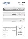
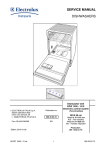
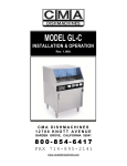
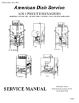
Effective: June, 2008
American Dish Service
ADS MODEL ASQ
GLASSWASHER
SERVICE MANUAL
900 Blake Street
Edwardsville, Kansas 66111
(913)-422-3700
© 05/08
IMPORTANT:
American Dish Service provides this information as a service to our customers.
Keep all instructions for future reference. Although ADS will make every effort to
make sure the information in this service manual is correct and up-to-date, ADS
does not certify that this is the case, and should you decide to utilize this manual,
you do so at your own risk. ADS reserves the right to alter or update this
information at any time without notice. Should you desire to make sure that you
have the most up-to-date information, we would direct you to the appropriate
document on our website: www.AmericanDish.com. The instructions and
guidelines in this owners manual are given with the assumption that the
dishwasher has been installed, operated, and maintained properly and in
accordance with all applicable Codes, Ordinances, and Safety requirements.
Failure to install, operate, and maintain the machine in this manner will void the
ADS Warranty. ADS assumes no liability or control over the installation,
maintenance (service), or operation of the equipment. Product failure due to
improper installation, maintenance, and operation is not covered under the ADS
Warranty.
WARNING:
During the operation of all dishmachines, chemicals, high voltage electricity, and
normal operational functions can cause harm, bodily injury, or worse if proper
installation, operation, and maintenance are not observed. It is imperative that
the operator(s) are trained in the operation and made aware of the hazards that
can exist. This is the responsibility of the owner of this equipment. When
installing, operating, or maintaining your dishwasher you must follow all
applicable safety requirements, including the wearing of approved personal
protective equipment.
TABLE OF CONTENTS
1.0
GENERAL
2.0
OPERATOR PROCEDURE
3.0
INSTALLATION
4.0
CHEMICALS
5.0
PREVENTIVE MAINTENANCE
6.0
TROUBLESHOOTING
7.0
REPAIR PROCEDURES
8.0
REPLACEMENT PARTS
1.0 GENERAL
The Model ASQ Glass washing machine is intended for under counter installation in bars
and restaurants. The unit has a circular rack divided into three compartments. This rack
is indexed manually so that one compartment is at the back of the machine in the wash
zone while the other two compartments are used for loading and unloading. The machine
uses liquid chemicals for sanitizing, rinse-aid and detergent.
During the first part of the cycle detergent is metered and the machine washes glasses.
It then drains and pre-rinses. Fresh water continues to flow into the machine until the
sump is full and the recirculating pump starts for the pumped rinse. Chlorine based
sanitizing chemicals are introduced during the rinse. When the cycle is complete the
rinse water remains in the machine to serve as wash water for the following load.
The rack is manually indexed bringing freshly washed glasses to the front compartment
and taking soiled glassware into the wash compartment. When the cycle start button is
pressed the next cycle begins.
Chemicals are stored in the front compartment accessible through the main door.
Electrical controls are enclosed in a cabinet on this door for accessibility. A small heater
maintains wash temperature when there are long periods between cycles.
2.0 OPERATOR PROCEDURES
2.1 DAILY START-UP
The following procedure should be
followed at the beginning of each
shift:
1. Inspect spray arm, screen and
sump (1) for cleanliness.
2. Inspect chemical containers to
insure an adequate supply for the
entire shift.
3. Turn on power switch (Green) at
the front of the machine.
4. Depress the fill button on the side
of the control cabinet until the
machine begins its cycle.
5. When the machine has finished
its first cycle check the water
temperature (2). If it has not
reached 120° F. (49°C.) then
press the cycle start button on
the front of the machine (Red).
Repeat this procedure until water
is at the proper temperature.
6. Load the first glasses into the left
hand side of the carousel.
Unlatch and rotate the carousel
1/3 revolution.
7. Press the cycle start button
(Red).
8. Subsequent loads of soiled
glasses may be placed on the
left hand side of the carousel
and clean glasses may be
removed from the right hand
side of the carousel while the
machine is in operation.
2.2 DAILY MAINTENANCE
At the end of his shift the operator should do the following (See Figure 2.2.1):
1. Drain water from the machine using the drain switch inside the door.
2. Remove the hood top (1) by lifting up approximately 1 inch and pulling
forward.
3. Remove the carousel by lifting approximately 1 ½ inches and pulling
forward.
4. Remove the splash shields (2) on either side of the carousel pivot by
pulling up at the center and sliding inward.
5. Remove the spray arm (3) by lifting it off the pivot.
6. Remove the scrap screen (4) and dispose of accumulated debris.
7. Thoroughly clean the inside of the sump and drain pan as well as all
removed parts.
8. Clean the spray arm.
9. Reassemble in reverse order.
10. Refill with water.
3.0 INSTALLATION
Adjust height and level of the machine
(See Section 7.1.3).
Connect the machine (1) to a
separately fused 20 amp circuit using
½ inch Sealtite. All electrical work
shall conform to the current edition of
the National Electric Code or to
applicable local codes, whichever is
most stringent. Check building wiring
for proper polarity and grounding.
Connect the fresh water inlet (2) to a
suitable source of hot water. Source
must be capable of supplying 140° F.
(60° C.) water with a recovery rate of
50 GPH.
Connect tail piece (3) to drain.
Place chemical suction tubes in their
proper containers.
RED – DETERGENT
GREEN – SANITIZER
BLUE – RINSE-AID
3.1 START-UP
Perform the following start-up
procedures. This should be done by a
qualified service representative.
1. Check voltage rating on name
plate (4) and confirm that electrical
supply is correct.
2. Visually inspect machine for
defects, shipping damage or
improper installation.
3. Prime chemical pumps
(See Figure 2.1.2).
4. Adjust chemical pump delivery in accordance with the recommendations of
Section 4.0 and 7.4.3.
5. Fill and operate machine. Insure that water level is correct and all components
work properly. Water level may be checked at the clear plastic tube inside the
front compartment.
6. Wash several loads. Insure that chemicals are metered in the appropriate
quantities and that glasses are clean.
7. Re-check for leakage at plumbing or cabinet.
8. Confer with owner to insure that he understands the operation and is
satisfied with the start-up.
3.2 WARRANTY
Record Model #, Serial #, and other necessary information on Warranty Card
and forward to:
AMERICAN DISH SERVICE
900 BLAKE STREET
EDWARDSVILLE, KS 66111-3820
4.0 CHEMICALS
All ADS machines require detergent and sanitizer for proper operation. A rinse-aid
may be used if desired.
Selection of the proper chemicals and the correct amounts will depend on several
factors. Proper selection is vital if optimum results are to be realized. It may be
necessary to change chemicals or adjust the quantity after the initial selection.
4.1 DETERGENT
Detergent is used to “emulsify” grease and loosen soil. Emulsification is a process
which breaks down grease into very small particles which then mix with water. The
detergent also reduces surface tension of the water to dissolve soluble matter.
The detergent selected must be designed for low-temperature dishwashing. Always
use established brands.
The proper quantity of detergent may vary over a wide range, and depends on the
following factors:
1.
2.
3.
4.
5.
Water hardness.
Type and amount of grease.
Length of time the dishes stand.
Iron content of water.
Detergent formulation.
For this reason, your chemical distributor should be consulted to determine the amount
which will give good results with lowest detergent usage. Your distributor should use the
Hatch Test Kit to test water hardness before making a recommendation. After the
machine has been in use or if conditions change, the setting can be readjusted for
optimum results.
4.2 SANITIZER
Sanitizer should be 6% solution of sodium hypochlorite. Initial setting is 5cc and
this should be checked periodically with a Chlorine Test Kit. Free chlorine in the
final rinse should be 50ppm or more.
4.3 RINSE-AID
Rinse-aid reduces surface tension and causes the rinse water to run off in sheets
rather than collect in droplets. This exposes more water surface to the air which
allows the glasses to dry faster and prevents spot formation.
The optimum amount of rinse-aid varies depending on many of the same factors
that affect detergent usage. Consult your chemical supplier and use
nationally recognized brands.
5.0 PREVENTIVE MAINTENANCE
The machine should be inspected
approximately once a month. The
following steps will prevent many
costly repairs.
1. Check that Operator Procedures
have been followed.
2. Inspect spay arm hub (1) for
tightness and spray arm for free
rotation (See Section 7.2.0).
3. Assemble machine and check for
distortion of sheet metal parts,
ease of assembly and proper
operation of carousel and
latch (2). Check for proper gap
between carousel and splash
guards (See Section 7.1.1).
4. Using manual fill switch (3), check
fill rate and water level.
5. During the machine cycle, check
the following:
a. Leakage at vacuum breaker
or cabinet.
b. Timer for proper operation.
c. Operation and flow of chemical
pumps.
d. Operation of pilot lights and
switches.
6. Remove control box cover (4)
and check the following:
a. Cycle counter and drive tube.
b. Chemical pumps and rotors
(lubricate if required).
c. Squeeze tubes.
d. Chemical intake and
discharge tubes.
e. Timer and switches.
f. Wiring for loose connections.
7. Inspect door hinges and latch.
TROUBLESHOOTING INDEX
DESCRIPTION
PAGE
6.0 TROUBLESHOOTING
2
Machine Will Not Operate – Green Light Off
Machine Will Not Operate – Green Light On
Cycle Will Not Resume After Wash
Machine Repeats Cycle
Pump Motor Will Not Operate
Pump Will Not Stop - Timer Is In Neutral
Motor Stops After Short Time
Recirculating Pump Leaks
Noisy Recirculating Pump
Low or Unsteady Pump Pressure
Detergent Pump Will Not Operate
Detergent Pump Will Not Stop
Sanitizer Pump Will Not Operate
Sanitizer Pump Will Not Stop
Rinse-Aid Pump Will Not Operate
Rinse-Aid Pump Will Not Stop
Chemical Does Not Flow
Heater Will Not Shut Off
Heater Will Not Operate
Fill Water Will Not Stop
Machine Does Not Fill
Water Leaks From Vacuum Breaker
Spray Arm Does Not Spin Properly
Glasses Not Clean – But Machine Operates
Excessive Foaming
3
4
5
6
7
8
9
10
11
12
13
14
15
16
17
18
19
20
21
22
23
24
25
26
27
DIAGRAMS
Electrical Component Identification
Interconnection Diagram with Chemical Alert
Ladder Diagram with Chemical Alert
Interconnection Diagram without Chemical Alert
Ladder Diagram without Chemical Alert
91-0001
91-0002
91-0003
91-9004
6.0 TROUBLESHOOTING
Scope – This section should be used to isolate problems if the machine malfunctions.
When a diagnosis has been made and confirmed, refer to Section 7.0 for repair
procedures.
CAUTION
ALWAYS turn off Power Switch when removing or replacing electrical covers.
ALWAYS use extreme care when checking voltages.
ALWAYS turn off Power Switch and disconnect circuit breaker or fuses before
making electrical repairs.
To use the troubleshooting charts, find the chart which describes the problem best
in the upper left hand corner. A series of questions is asked and should be answered
“YES” or “NO”. This answer leads to the next question until the problem is isolated and
a repair is described. When the electrical control system is involved, a portion of the
circuit diagram is included on the chart to assist in understanding.
Unless otherwise stated, voltage measurements should be taken from the
neutral buss.
REPAIR PROCEDURES INDEX
DESCRIPTION
PAGE
7.0
REPAIR PROCEDURES
2
7.1
CABINET ASSEMBLY
7.1.1 Carousel Adjustment
7.1.2 Height Adjustment
SPRAY SYSTEM
7.2.1 Pressure Check
7.2.2 Bearing and/or Spray Arm Replacement
PUMP/MOTOR ASSEMBLY
7.3.1 Upper Pump Housing Replacement
7.3.2 Pump/Motor Replacement
CONTROL SYSTEM
7.4.1 Timer Motor Replacement
7.4.2 Cam Adjustment
7.4.3 Timer Switch Replacement
7.4.4 Motor Relay Replacement
7.4.5 Replacement of Start Winding Relay
7.4.6 Chemical Pump Replacement
7.4.7 Heater Replacement
7.4.8 Thermostat Replacement
7.4.9 Float Switch Replacement
7.4.10 Power or Cycle Start Switch Repair
7.4.11 Cleaning Flow Indicator
7.4.12 Flow Indicator Replacement
FRESH WATER PLUMBING
7.5.1 Clean/Replace Strainer Screen
7.5.2 Replace Shut-Off Valve Packing
7.5.3 Service Solenoid Valve Diaphragm
7.5.4 Replace Solenoid Valve Coil
7.5.5 Overhaul Vacuum Breaker
7.5.6 Plumbing Removal
3
3
5
6
6
7
8
8
10
11
13
13
15
15
15
16
16
16
16
17
19
19
20
20
20
23
23
23
25
7.2
7.3
7.4
7.5
7.0 REPAIR PROCEDURES
Repair procedures are organized around the major sub-assemblies of the
machine. Most common procedures are included. In addition to specific
procedures, each major sub-assembly is discussed with respect to its
construction and operation. Before attempting any repair, maintenance
personnel should be thoroughly familiar with the construction and operation
of the equipment and should be certain that the diagnosis is correct.
7.1.0 CABINET ASSEMBLY
(See Figure 7.1)
The cabinet of the Model ASQ
Glasswasher is of welded stainless steel
construction. The lower section of the
cabinet has two compartments. The
motor compartment houses the pump
motor, solenoid valve and several
electrical components. Except during
maintenance the motor compartment
panel (1) must always be in place.
The front compartment provides storage
areas for washing, sanitizing and rinseaid chemicals. The control box (2)
which is mounted o the door is also
contained in this compartment.
The carousel (3) which holds the
glasses is supported at the bottom on a
pivot pin and at the top by a ring on the
hood top. Alignment of the carousel is
attained by moving the lower pivot left or
right. On some machines, shims may
be used to position the pivot front to
rear. A latching mechanism maintains
position of the carousel.
7.1.1 CAROUSEL ADJUSTMENT
(See Figure 7.1.1)
Alignment of the carousel is critical to
proper operation and sealing of the
wash compartment. This alignment is
made at the factory but if the machine is
damaged or a new hood is installed this
alignment could be altered. Before
making any alignment changes be
absolutely sure that the hood and hood
top are seated firmly in place and there
are no broken or protruding parts.
1. Assemble the machine and check
the gap above the carousel divider
and below. This gap should be
approximately 1/8 inch at the top and
3/16 inch at the bottom and should
be even along the entire length and
the same on both sides.
2. Adjust the lower pivot in order to attain an even gap along both sides at the top of the
carousel.
3. The width of the gap may now be adjusted by installing or removing spacers at the bottom
of the carousel.
7.1.2 HEIGHT ADJUSTMENT
(See Figure 7.1.2)
1. Place level (1) on top of machine in both front-back and side-side directions to determine if
machine is out of level and in which direction.
2. Adjust level by turning lower portion of bullet feet (2) with an open-end crescent wrench.
7.2.0 SPRAY SYSTEM
The Model ASQ Glasswasher spray system consists of a rotating spray arm with “V” type
spray jets. The arm rotates on a stainless steel pivot and uses the hydro-static principle in which
fluid is forced under pressure between the bearing surfaces. The bearing therefore rides on a
thin film of water. The spray arm may be readily removed for daily cleaning.
7.2.1 PRESSURE CHECK
(See Figure 7.2.1)
1. Install special pressure fitting (1) on one end of lower spray arm (2) and attach pressure gauge
which reads 0.20 PSI.
2. Close doors and start machine.
3. Record pressure during wash portion of cycle. If pressure fluctuates, record maximum and
minimum pressure.
4. Normal pressure may range from 8 PSI (5600 KG/M2) to 12 PSI (8400 KG/M2). If pressure is
less than 8 PSI (5600 KG/M2) or fluctuates more than 3 PSI (2100 KG/M2), refer to
Section 6.11.
7.2.2 BEARING and/or SPRAY ARM REPLACEMENT
1. Remove spray arm.
2. Inspect bearing for scoring or excessive wear and replace if necessary.
3. Inspect spray arm hub for wear or scoring and jets for wear.
4. Replace spray arm as required.
7.3.0 PUMP/MOTOR ASSEMBLY
The Model ASQ Glasswasher uses an integral pump and motor assembly. Field repair of this
unit is not recommended with the exception that the upper housing may be replaced if damaged
or the gasket may be replaced if leakage occurs. Any other defects normally cause extreme
damage to the pump or motor windings and replacement of the entire unit is the most economical
and reliable repair.
This unit contains a recirculating pump for spraying water over the glasses as well as drain pump
which pumps soiled water from the machine. The recirculating pump is activated when the motor
is driven in the forward direction and drain pump is active when the motor reverses. The motor
has three windings. The main winding energizes and provides power for the pump. The forward
or reverse windings are energized for approximately ½ second when the motor is first started to
initiate rotation in the proper direction. Once the motor is at operating speed the starting winding
is de-energized by the motor start relay and the main winding continues to rotate the motor in
either the forward or reverse.
Motor burn outs may be caused by failure of the motor start relay or a loose connection in the
motor starting circuit. If a motor has been replaced because of burn out it is imperative that the
main and starting circuits be checked and the motor start relay replaced.
7.3.1 UPPER PUMP HOUSING REPLACEMENT
(See Figure 7.3.1)
1. Remove hood top, hood, carousel and splash shields.
2. Remove spray arm and scrap tray.
3. Remove eight screws (1) around the top of the pump housing (2) and remove housing.
4. Do not move or rotate any portions of the lower pump assembly.
5. Reassemble in reverse order.
7.3.2 PUMP/MOTOR REPLACEMENT
1. Remove hood top, hood sides, splash shields, spray arm and scrap tray.
2. Remove motor compartment panel and floor.
3. Disconnect motor from wiring harness.
4. Remove eight screws attaching motor to sump bottom.
5. Remove motor/pump assembly.
6. Remove spray arm pivot from motor assembly.
7. Reassemble in reverse order making certain that the motor is oriented properly.
8. Before energizing machine connect a neon test light across the two lower terminals of the
motor starting relay.
9. Press the “Power On” button and “Cycle Start” button, the neon test light should go out as
soon as the main motor relay is energized. It will remain out for approximately ½ second and
then light again. If this does not occur IMMEDIATELY shut off power to the machine. Check
the motor starting circuits and replace the motor start relay.
7.4.0 CONTROL SYSTEM
(See Figure 7.4)
The timer (1) consists of a drive motor and seven cams. These cams open and close seven
switches which control most functions of the machine.
Switch #1 (LS1) controls the timer motor. When the machine is off and the timer is in its neutral
position, no power is supplied to the timer motor. When the machine cycle starts, Switch #1 is
activated and the timer motor drives the cams through their cycle.
Switch #2 (LS2) supplies power to the MOTOR RELAY which powers the main motor windings.
Switch #3 (LS3) activates either the forward or reverse motor start windings through the MOTOR
START RELAY.
Switch #4 (LS4) controls the Solenoid Valve which supplies fresh water to the machine. Its cam
is adjustable in order to control the starting point of the purge cycle and the water level.
Switches #5 (LS5), #6 (LS6), and #7 (LS7) control the detergent (RED), sanitizer (GREEN) and
rinse-aid (BLUE) metering pumps respectively. The cams which operate these switches are also
adjustable.
R1, the Instant Start Relay (2) supplies power to the timer and pump motors for approximately
one second after the cycle start button is depressed. This allows time for Cam #1 to actuate.
R2, the Cycle Resume Relay (3) restarts the timer motor when the water level is near its proper
point. Water continues to flow for several seconds and this time is adjustable to provide the exact
water level required.
7.4.1 TIMER MOTOR (4) REPLACEMENT
1. Remove two mounting screws and nuts.
2. Pull motor to the left, away from timer frame until stopped by the pinion.
3. Slide motor up and forward so that motor shaft slides out slot in frame.
4. Disconnect wires and reconnect to new motor.
5. Replace motor in frame making sure that gear and pinion are meshed and that the motor is
flush against the frame with the shaft bushing locked in place at the bottom of the slot
7.4.2 CAM ADJUSTMENT
(See Figure 7.4.2)
The timer cams which control the water solenoid valve and chemical pumps are adjustable.
These cams are split with a left and right side. The right side of the cam sets the point at which
the solenoid valve opens or the chemical pump starts. The left side sets the point at which the
solenoid valve closes or chemical pump stops.
THE RIGHT SIDE OF CAM SHOULD
ALWAYS REMAIN AT FACTORY SETTING.
Adjustment of the left side will determine the length of time the solenoid valve is open or the
chemical pump operates and thus controls the amount of water or chemical introduced into the
machine.
Cams are adjusted using a special wrench which fits into notches on the side of the cam.
The cart shows factory cam settings. The right side of adjustable cams should always be at
factory setting but the left side may be changed to suit field conditions.
7.4.3 TIMER SWITCH REPLACEMENT
1. Remove small Phillips head screw
which holds the timer switch bracket
to the timer frame.
2. Move the switch straight to the rear
away from the timer frame
approximately 3/8 inch.
3. Separate the switch from its bracket
and attach the bracket to the
replacement switch.
4. Transfer wires one at a time from the
old switch to the new switch.
5. Replace bracket and screw.
7.4.4 MOTOR RELAY REPLACEMENT
1. Remove four wires from the motor
start relay (5).
2. Remove two screws and nuts which
attach the motor relay to the cabinet
side.
3. Install the new motor relay and attach
wires.
7.4.5 REPLACEMENT OF START
WINDING RELAY (6)
1. Remove the two screws which hold the
relay bracket to the timer cabinet.
2. Attach new relay to the cabinet.
3. Remove wires one at a time from the old
relay and reattach to the new relay.
CAUTION
Install relay in upright position!
Care must be taken to insure that wires are attached to this relay
properly. Improper wiring will cause immediate motor burn out.
7.4.6 CHEMICAL PUMP REPLACEMENT
1. Loosen the two mounting screws which
attach the chemical pump to its bracket.
2. Carefully remove the squeeze tube from
the chemical intake and chemical
discharge tubes.
3. Pull the pump (7) forward out of the
cabinet and disconnect wires.
4. Reassemble in reverse order with the
new pump.
7.4.7 HEATER REPLACEMENT
1. Remove motor compartment panel.
2. Remove attachment nuts and heater (8).
3. Remove ceramic insulating caps and
disconnect wires.
4. Reassemble in reverse order.
7.4.8 THERMOSTAT REPLACEMENT
1. Remove motor compartment panel.
2. Remove two screws (1) which hold
thermostat (9) to bracket.
3. Disconnect wires and attach to new
thermostat.
4. Install new thermostat and screws.
7.4.9 FLOAT SWITCH REPLACEMENT
1. Remove motor compartment panel.
2. Disconnect two wires from float
switch (10).
3. Remove clip and float.
4. Remove stem.
5. Reassemble in reverse order making sure that float is installed right side up.
7.4.10 POWER or CYLE START SWITCH REPAIR
(See Figure 7.4.10)
1. Disconnect wires from all four terminals.
2. Remove lens (1) from front of switch.
3. Remove collar (2).
4. Remove small gasket (3).
5. Remove remainder of switch assembly from the door.
6. To replace lamp transformer insert a screwdriver under the locking tabs on one side of the
transformer (4) and then on the opposite side. Reverse steps 1 thru 5.
7. To replace switch operator insert screwdriver under locking tabs at the front of the switch and
pry up. Do the same on the opposite side.
8. Install the operator. Reverse steps 1 thru 5.
9. Replace contact block (5).
1. Insert a small screwdriver in the slot at the rear of the contact block and separate the
blocks.
2. Slide the blocks forward and backward, do not attempt to pry apart laterally.
3. Assemble the new contact block (blocks) and insert the lamp holder from the front.
Apply sufficient force to push lamp holder into place.
10. Reassemble in reverse order.
CAUTION
Flow indicators and chemical system contain
caustic chemicals. Flush system and protect
eyes before performing service.
7.4.11 CLEANING FLOW INDICATOR (11)
(See Figure 7.4)
1. Remove chemical tubes from detergent and sanitizer containers and place in a container
or clean water.
2. Operate both pumps using the prime switches until the chemical tubes are flushed and
filled with clean water. If flow indicator still remains cloudy remove the silicone tubes from
both ends and clean with rags and pipe cleaner.
3. Reassemble.
7.4.12 FLOW INDICATOR REPLACEMENT
1. Remove chemical suction tubes from chemical containers and place in clean water. Flush
the system using the prime switches.
2. Remove silicone rubber tubes from both ends of the flow indicator and remove glass balls.
3. Remove screws attaching indicator to door.
4. Install new indicator reversing steps 1, 2, and 3.
7.5.0 FRESH WATER PLUMBING
(See Figure 7.5)
Fresh water is introduced into the machine through the fresh water plumbing assembly. A
manual shut-off valve in the front compartment closes off the system when servicing is required
on other components. Water flows from the shut-off valve through a strainer and into the water
solenoid which controls water flow into the machine. A vacuum breaker provides back flow
protection.
7.5.1 CLEAN/REPLACE STRAINER SCREEN
1. Remove strainer cap (1).
2. Remove screen and inspect.
3. Slightly open shut-off valve (2) to flush loose scale or dirt from the strainer housing.
4. If screen is clogged, soak in lime remover. If damaged, replace.
5. Reassemble in reverse order.
7.5.2 REPLACE SHUT-OFF VALVE PACKING
1. Shut off water supply upstream of machine.
2. Remove screw and lift off valve handle.
3. Using ¾ inch wrench, remove valve bonnet (3).
4. Disassemble stem, packing and plug.
5. Clean plug, stem and bonnet using lime remover and steel wool.
6. Install new packing and reassemble in reverse order.
7.5.3 SERVICE SOLENOID VALVE DIAPHRAGM
(See Figure 7.5.3)
1. Shut off water with manual valve.
2. Remove screw (1) and lift off solenoid.
3. Unscrew valve bonnet (2) using spanner or channel-locks. Insure that valve body (3) is
held firmly to prevent damage to plumbing.
4. Remove bonnet (2), o-ring (4) and diaphragm (5).
5. Clean screen (6) and valve body.
6. Inspect bleeder holes (7) for plugging and diaphragm for damage.
7. Reassemble in reverse order using new parts from diaphragm kit.
8. Clean strainer screen (7). (See Figure 7.5)
7.5.4 REPLACE SOLENOID VALVE COIL
(See Figure 7.5.3)
1. Remove screw (1) on top of solenoid coil housing.
2. Remove coil and housing.
3. Disassemble housing and replace coil.
4. Install housing on valve body and replace screw.
7.5.5 OVERHAUL VACUUM BREAKER
(See Figure 7.5.5)
1. Remove cap by turning counter clockwise with channel-locks or pipe wrench.
2. Remove plunger (1) and gasket.
3. Clean gasket seat, plunger seat and stem using steel wool and lime remover.
4. Reassemble in reverse order using new plunger and gasket.
7.5.6 PLUMBING REMOVAL
(See Figure 7.5)
Most repairs on fresh water plumbing can be done without removing the plumbing assembly from
the machine. However, when a valve or a strainer body must be replaced the plumbing must be
completely disassembled and removed. The following procedure applies:
1. Remove 45° elbow, washer and gasket from inside the machine sump (4).
2. Rotate the pipe attached to the discharge at the vacuum breaker 90° to an upward direction
as shown.
3. Using a pipe wrench rotate the vacuum breaker inlet pipe and remove this portion of the
plumbing from the machine.
4. Remove the elbow (5).
5. Remove lock nut (6) on plumbing inlet.
6. Remove screw which attaches the gusset to the front sump panel.
7. Remove lower plumbing assembly from the machine.
8. Replace individual parts as required and reassemble in reverse order using teflon pipe
fitting tape on all joints.