1
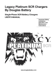
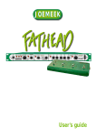
CORNELL MODEL NC-102D
CONTROLLER FOR
4000 & 4500 SERIES
DUAL / TRIPLE-STATUS NURSE CALL
INSTALLATION & SERVICE MANUAL
CORNELL Communications, Inc.
7915 N. 81st St.
Milwaukee, WI 53223
www.cornell.com
800-558-8957
The purpose of this document is to aid the Installer or Service Person in properly installing and
troubleshooting the NC-102D Controller within a Cornell Nurse Call System.
If this is your first Dual or Triple-Status Cornell Nurse Call System, it is suggested that you should read
the entire manual, in order to thoroughly familiarize yourself with this key component of the system.
This manual consists of the following sections:
TABLE OF CONTENTS:
Section 1
FUNCTIONAL DESCRIPTION
Pages 1.1 – 1.4
This section will help you understand the terminology used
within the NC-102D, and theory of operation
Section 2
CALIBRATION PROCEDURE
Page 2.1
Procedure for field calibration of NC-102D
Section 3
INSTALL / TROUBLESHOOTING GUIDE
Pages 3.1 – 3.8
Provides guidance in troubleshooting NC-102D / related
problems
Section 5
TERMINAL DEFINITIONS
Pages 4.1 – 4.5
Describes intended function and limitation of each NC-102D
Termination
Revised 06/01/07 RDG
page A
CORNELL MODEL NC-102D – FUNCTIONAL DESCRIPTION
The purpose of this document is to aid the Installer, Service Person, or Designer in understanding the
purpose and function of the NC-102D Controller within a Cornell Nurse Call System.
OVERVIEW:
The NC-102D Controller is the functional core of a dual or triple-status Nurse Call System. It is
normally used in conjunction with Cornell 4000-Series and 4500-Series Dual Status products.
The NC-102D controls Audible & Visible indication of the different call priorities within a system.
Audible Indication – The NC-102D ensures that only the highest priority that is present is
audibly indicated at sounders, that are built into the Annunciators and Duty Stations.
Visible Indication – The NC-102D generates the different flash rates that are used to indicate the
various call priorities via Annunciator and Duty Station LEDs and Dome Lights/Zone Lights.
Cornell 4000 and 4500-Series Nurse Call Systems utilize a “Common Positive” wiring/operation
scheme – this means that one side of every device (Stations with LEDs or Electronic Latching, Dome
Lamps, Annunciators, Sounders, etc.) is tied to the Positive side of the 24-Volt System Power Supply.
Indication and Control functions are accomplished by switching the Negative side of the system.
CALL PRIORITIES:
The NC-102D has the capability to identify and differentiate between 3 types of Cornell-Defined system
calls. The 3 types of calls, and their letter designations are described as follows:
PRIORITY-1
[HIGH]
(LETTER DESIGNATION = “P” PRIORITY)
This type of call has the highest priority status, and is usually used for Dwelling Unit Smoke
Detectors, Code Call Stations, or “Panic” Alarms.
Audible Indication
Visible Indication
= 2 Pulses per second, Rapid Pulse (2Hz – 50% duty cycle)
= 2 Flashes per second, Rapid Pulse (2Hz – 50% duty cycle)
PRIORITY-2
[MIDDLE]
(LETTER DESIGNATION = “F” FLASH)
This type of call has middle priority status, and is usually used for Bathroom (Pull-String)
Stations.
Audible Indication
Visible Indication
= 1 Pulse per second, Slow Pulse (1Hz – 50% duty cycle)
= 1 Flash per second, Slow Pulse (1Hz – 50% duty cycle)
PRIORITY-3
[LOW]
(LETTER DESIGNATION = “S” STEADY)
This type of call has the lowest priority status, and is usually used for Routine calls from Bedside
(Call Cord) Stations.
Audible Indication
Visible Indication
= 1 Pulse every 6 seconds (Slow Pulse (1Hz – 50% duty cycle)
= 2 Flash per second, Slow Pulse (1Hz – 50% duty cycle)
CALL SENSING:
Three Current-Sensing Outputs are incorporated into each NC-102D Controller – One for each Priority
Condition, and designated by letters as defined above:
•
•
•
“P” Current-Sensing Output for High-Priority Calls, and their associated Stations
“F” Current-Sensing Output for Mid-Priority Calls, and their associated Stations
“S” Current-Sensing Output for Low-Priority Calls, and their associated Stations
Revised 06/01/07 RDG
page 1.1
CORNELL MODEL NC-102D – FUNCTIONAL DESCRIPTION
Each of these Current-Sensing Outputs performs both an Output and an Input function, as follows:
OUTPUT FUNCTION – SIGNAL GENERATOR
Each Station used within the associated Nurse Call System derives Negative 24-Volt Power from
one of the Current-Sensing Outputs. Each Current-Sensing Output also provides a SignalGenerator function, which affects operation of the LEDs and Lamps associated with it:
•
“P” (PRIORITY) OUTPUT
o Associated Stations = Smoke Detectors, Panic Alarms, or Code Blue Stations
o Signal-Generator = Lights & LEDs fed via this Output will Fast Flash at 2 Hz.
•
“F” (FLASH) OUTPUT
o Associated Stations = Bathroom (Pull-Cord) Stations
o Signal-Generator = Lights & LEDs fed via this Output will Slow Flash at 1 Hz.
•
“S” (STEADY) OUTPUT
o Associated Stations = Bedside Patient (Call-Cord) Stations
o Signal-Generator = Lights & LEDs fed via this Output will illuminate Steadily.
INPUT FUNCTION – CURRENT SENSING:
Each Current-Sensing Output has the capability to continuously monitor the amount of current
that is drawn from it. All other functions of the NC-102D depend upon this function.
•
When no Stations or a particular type are actuated, little or no current will be drawn from the
associated Current-Sensing Output. This is defined as the “Idle” state.
•
Whenever a Station or Detector is actuated, a measurable increase in current will be detected
via the associated Current-Sensing Output. This is defined as the “Active” state.
•
In order to be sensed as “Active”, a minimum amount of current needs to be drawn from each
Current-Sensing Output. This is defined as the “Minimum Trigger Current”.
•
Lastly, certain types of devices, when connected to the system, will cause a small amount of
current to be continuously drawn from the Current-Sensing Outputs that are used within the
system. This situation will be referred to as “Idle Current”. In order to ignore such Idle
Current loads, a Calibration function has been designed into the NC-102D.
VISIBLE INDICATION
On Nurse Call Systems that are equipped with NC-102D Controllers, Visible Indication is accomplished
via Annunciator LEDs and via Corridor Dome Lamps and Zone Lamps.
•
For Most Annunciators, a single LED will be provided for each room, which illuminates
according to the Signal Generator Output Functions, as described above (Steady, Slow Flash, or
Fast Flash). Proper operation of these LEDs depends upon the stations being properly
interconnected, as shown in the proper “typical” dual or triple-status Cornell Wiring Diagrams.
•
Where Single Corridor Dome Lamps are used, they are usually interconnected to the same
circuits that drive the Annunciator LEDs, and behave in the same manner.
•
Where Multi-Lamp Corridor Dome Lamps and Zone Lamps are used, they are usually wired
such that a separate lamp, sometimes color-coded, is utilized for each status condition being
used. In this case, multiple status conditions can be indicated simultaneously.
•
Additional Visible Indication Outputs are provided for use in conjunction with Duty Stations.
These are intended to cover the particular combination of priorities present in each system.
Revised 06/01/07 RDG
page 1.2
CORNELL MODEL NC-102D – FUNCTIONAL DESCRIPTION
AUDIBLE INDICATION SCHEME
On Nurse Call Systems that are equipped with NC-102D Controllers, Audible Indication is
accomplished via Piezo Sounders or Tone-Boards that are built into Annunciators and Duty Stations.
The NC-102D contains several Outputs and Inputs that are intended for Audible Indication Functions.
Actuation of these outputs depends upon calls sensed via the Current-Sensing Outputs.
The NC-102D simultaneously monitors all three of the Current-Sensing Outputs. Based upon internal
control logic functions, the Audible Output Circuits only respond to the highest priority status condition
that is present at any given time:
•
The “P” (Priority) Audible Output Function will take precedence over any “F” or “S” Audible
Output Functions. This occurs:
•
The “F” (Flash) Audible Output Function will take precedence over any “S” Audible Output
Function. This occurs:
•
Whenever the “P” Current-Sensing Output is Idle AND
Whenever the “F” Current-Sensing Output is Idle AND
When the “S” Current-Sensing Output is Active
Audible Output Functions will be automatically Silenced:
•
Whenever the “P” Current-Sensing Output is Idle AND
When the “F” Current-Sensing Output is Active, regardless of the state of the “S”
Current-Sensing Output.
The “S” (Steady) Audible Output Function will occur only when Type “S” calls are the only
calls present on the system. This can only occur:
•
Whenever the “P” Current-Sensing Output is Active, regardless of any other
Current-Sensing Output.
Only when ALL 3 Current-Sensing Outputs are Idle
Audible Output Functions automatically Escalate as higher-priority calls are sensed, and DeEscalate as higher-priority calls are cleared, according to this priority scheme.
NON-MUTABLE AUDIBLE OUTPUTS:
Non-Mutable Audible Outputs operate in strict accordance with the Audible Indication Scheme outlined
above. Sounders that are connected to Non-Mutable Audible Outputs will continue to produce Audible
Signal Sounds until ALL Current-Sensing Outputs are Idle.
MUTABLE AUDIBLE OUTPUTS:
Mutable Audible Outputs operate in the same manner as Non-Mutable Audible Outputs, with the
following exceptions:
•
Associated “Mute” Inputs are provided, in order to permit operation of the Muting feature.
•
Whenever a “Mute” Input is momentarily actuated, the associated Mutable Output will be
silenced.
•
The Mutable Output will automatically re-sound whenever a New Call occurs (whenever the
current draw sensed by ANY Current-Sensing Output increases measurably).
•
The “Mute” feature IS NOT currently utilized on any “standard” Cornell Nurse Call products.
Revised 06/01/07 RDG
page 1.3
CORNELL MODEL NC-102D – FUNCTIONAL DESCRIPTION
CALIBRATION FEATURE:
The NC102D has been equipped with a feature that allows the system to ignore any idle current devices
connected to the system. An idle current device is defined as any component connected to an “S”, “F”,
or “P” Current-Sensing Output, which requires a current draw in order to operate in a deactivated state.
EXAMPLE – CORNELL ZONE LIGHT
The Z-103 senses current in the circuits that feed the portion of the system that it serves. In order
to perform this function, it requires a small amount of current to operate its internal sensing
circuits – even when none of its associated lamps are illuminated.
Without the calibration procedure, the Idle Current required by one or more such Zone Lights
may be sensed by the Current-Sensing Outputs – which would create false call indication.
Once it is calibrated, the NC-102D that serves this system will disregard the idle current caused
by such devices, and will then operate as follows:
(Idle Current) + (Trigger Current) = Indicate call for increase due to Trigger Current
Refer to the “Cornell Model NC-102D – Calibration Procedure” for more detailed information.
DIAGNOSTIC FEATURES:
In order to aid the installer or service personnel in installation and troubleshooting, the NC-102D
incorporates the following diagnostic features:
LED Indicators are provided, aligned with the Terminal Strip, which indicate the Active State of
the associated Inputs and Outputs.
• The NC102D also has a full RS232 diagnostic screen output for system troubleshooting. This
feature is reserved for internal use by Cornell Communications, Inc., and for particular custom
configurations.
•
Revised 06/01/07 RDG
page 1.4
CORNELL MODEL NC-102D – CALIBRATION PROCEDURE
WHEN SHOULD CALIBRATION BE PERFORMED?:
A.
NEW SYSTEM INSTALLATIONS:
Cornell recommends that the Calibration procedure should be performed for new systems,
regardless of the equipment used in the system.
B.
IDLE CURRENT ON S, F, OR P:
The NC-102D will require calibration when there will be any idle current on any of the CurrentSensing Outputs “P”, “F”, or “S”, with no calls entered into the system.
An example of idle current is when one or more Cornell Z-103 zone lights are installed in the
system. (The circuitry within the Z-103 draws current, even when no lights are illuminated.)
C.
ADDITIONS / CHANGES TO AN EXISTING SYSTEM:
If Z-103 Zone Lights, or other idle current devices are added to an existing system or removed,
or if the NC-102D replaces an older model controller, re-calibration will be necessary.
WHAT SWITCHES ARE USED IN THE CALIBRATION PROCEDURE?:
The following descriptions assume that the NC-102D is mounted with:
•
•
14-Position Terminal Strip – at Bottom
Large Integrated Circuit Chip – at Top
The following two switches will be utilized:
•
•
S1 = Sliding “CAL” switch - located at Top Center of circuit board
S2 = Small Momentary Pushbutton “RST” – located at Top Left of circuit board (Near
jumper block)
CALIBRATION PROCEDURE:
Follow the following steps EXACTLY, in order to calibrate the NC-102D Controller:
1.
CHECK SYSTEM FOR ACTIVE CALLS
Make sure there are no active calls in the system.
2.
SET S1:
Move the sliding switch (S1, labeled “CAL”) to the right (AWAY from the adjacent Red LED).
3.
PRESS AND RELEASE S2 – Momentarily press the system reset switch (S2, labeled “RST”).
4.
OBSERVE RED DIAGNOSTIC LED “DS2” (located adjacent to Switch S1):
After Switch S2 is released, LED “DS2” should perform the following sequence of events:
•
Initially, it will illuminate in a Steady manner for a few seconds
•
It will start blinking rapidly (you will clearly see the on/off flashing) – this flashing indicates
that system calibration is complete.
5.
TURN CALIBRATION SWITCH “S1” OFF:
Move the sliding switch (S1, labeled “CAL”) to the Left (TOWARDS the adjacent Red LED).
6.
OBSERVE RED DIAGNOSTIC LED “DS2” (Same Red LED as before):
After Switch S1 is turned off, this LED should also turn off.
END OF PROCEDURE - The NC102D system is now ready for operation.
Revised 06/01/07 RDG
page 2.1
CORNELL MODEL NC-102D – INSTALL / TROUBLESHOOTING GUIDE
The purpose of this document is to aid the Installer or Service Person in properly installing and
troubleshooting the NC-102D Controller within a Cornell Nurse Call System.
This document incorporates tips and symptoms that have been observed by Cornell Technical Support
over the past years – allowing you to learn from others’ mistakes, and saving you time and money.
FIRST THINGS FIRST:
First, before installing or servicing an NC-102D Controller, it helps to understand the function and
features of the Controller. The following documents are part of the NC-102D Installation Manual, and
are also available via Cornell’s website (www.Cornell.com):
•
•
•
NC-102D Functional Description
NC-102D Calibration Procedure
NC-102D Pin Definitions
Second - ensure that you have the correct installation drawings for the particular system being installed /
serviced. If you don’t have them, obtain them from Cornell’s website before heading to the jobsite.
Third – if the problems does not encompass the entire system, or ALL of a particular station type, the
source of the problem is probably not the NC-102D.
Lastly, keep an open mind – sometimes, what appears to be the “problem”, is actually a Symptom of the
problem. REPLACING A COMPONENT, WITHOUT FIRST ATTEMPTING TO FIND OUT WHY
IT FAILED, OFTEN RESULTS IN THE SAME COMPONENT BECOMING “BLOWN” AGAIN.
POWER SUPPLY-RELATED PROBLEMS AND TROUBLESHOOTING:
Although the Power Supply is a different component from the NC-102D, power supply problems are
often mistaken for NC-102D problems. This section of the Troubleshooting and Installation Guide deals
with power supply problems, and some tips that you can use in diagnosing and fixing such problems.
BE CAREFUL! – Dead and/or Damaged Power Supplies are often the symptom of some other problem.
Check your field wiring and other components before simply replacing the power supply. Otherwise,
you may simply end up with a second burned-out power supply.
SYMPTOMS OF POWER-SUPPLY RELATED PROBLEMS:
• System Totally “Dead” (It’s probably the Power Supply, not the NC-102)
•
All system LEDs and Lamps function “normally”, but All Annunciator / Duty Station Sounders
are not working. (Check Voltage)
•
All Station Types (Bed Stations and Bath Stations) are experiencing the same problem –
particularly if lamps appear dim, or if they fail to light once several stations are actuated.
(Check Load Performance of Power Supply.)
•
System worked normally for a few hours / a few days, and then experienced problems (check
Primary AC and Batteries, if so equipped [if this is the case, be sure to check “Battery
Problems”, and “Failed after a few days/hours” near the end of this Guide]).
(continued on next page)
Revised 06/01/07 RDG
page 3.1
CORNELL MODEL NC-102D – INSTALL / TROUBLESHOOTING GUIDE
DEAD POWER SUPPLY
Sometimes, it’s the simple things that get overlooked:
•
Check the Circuit Breaker / Measure incoming Primary AC. If it’s not there, it’s only natural
that the system is not working. If the breaker was turned Off, you have probably found the
problem. If it was tripped, you are probably “on the trail” of some greater problem.
•
If 120 VAC (most of U.S.A.) IS present:
o Check any fuses / overload protection associated with the Power Supply (refer to
instructions for particular power supply).
o Try Disconnecting the Batteries (If so equipped) – batteries sometimes experience
internal Short-Circuiting. When the charger circuits attempt to charge shorted batteries,
this sometimes causes overload protection to kick-in, causing shutdown. If this is the
case, replace the batteries (always date-mark new batteries).
o Try disconnecting the Supply’s DC output. Many power supplies use “foldback” output
protection. When an overload or short occurs on the output, the unit shuts down. If
disconnecting the field wiring appears to restore operation, one of two cases is likely:
•
An overload or short-circuit is present in the system, “downstream” of the power
supply (more testing will be needed to find it)
If the Power Supply fails under load, something may be wrong with it, or with it’s
overload protection circuitry. However, even if you know that the power supply
is bad, it is almost always prudent to check the remainder of the system for
unusual loads, and for shorts and ground faults before replacing it.
If a higher Voltage (208 / 220 VAC) is present – ensure that the power supply was intended to
operate on this AC voltage. [Most Commercial Lighting Circuits operate on 208 or 220 VAC,
while outlets are on 120 VAC.] (Most Cornell Power Supplies are not designed for 208/220 –
you probably need to replace the power supply, after obtaining a proper 120 VAC feeder for it.)
WRONG OUTPUT VOLTAGE
ALL Cornell 4000 and 4500-Series Nurse Call Systems are designed to operate on 24-Volts DC.
Measure the Power Supply Output Voltage, and observe the following:
•
Approximately 23 to 28 Volts is acceptable, depending upon how far the power supply is from
the measurement location. If your measurement is significantly different, check the following:
o Make sure that the Power Supply is set at the correct Voltage. Most recent Cornell
Power Supplies are configurable for both 12 and 24-Volt operation – if you are getting
12-Volts, set it for 24 (See Power Supply Instructions).
o Older Cornell Linear Power Supplies (these have Big Transformer) sometimes utilized
center-tapped transformers (two 12-Volt secondary windings, rather than one 24-Volt).
If one winding goes bad, the supply output is affected – you will probably measure
approximately 12 Volts DC, with significant AC “ripple”.
o If the Voltage is too high (over approximately 28-Volts):
Attempt to adjust the output Voltage. Some Cornell Power Supplies are equipped
with trim potentiometers for this purpose.
If the Output Voltage cannot be adjusted, the regulator circuitry may be bad, and
the Power Supply may need to be replaced.
Revised 06/01/07 RDG
page 3.2
CORNELL MODEL NC-102D – INSTALL / TROUBLESHOOTING GUIDE
BATTERY PROBLEMS / BATTERY CONFIGURATION ERRORS
If a new Power Supply contains Batteries, ensure that they are properly configured. Where any Power
Supply contains Batteries, test them to make sure that they are “good”.
If you work with sealed Gell-Cell (Immobilized Electrolyte) Batteries on a regular bases, Cornell
suggests that you should purchase an Electronic Battery Load Tester. Measuring Voltage is OK, but
sometimes, cells that put out proper voltage when measured fail when under load.
Some symptoms of Battery Problems are as follows:
•
Total System Failure – If system resumes normal operation when batteries are disconnected,
check for cells that are internally short-circuited.
•
The System functions for a day or two, then experiences total failure.
•
The lights and LEDs function normally, but the Sounder/Audio is not working
In the last two cases -- particularly new systems, or where a new Battery Back-Up Power Supply has
been installed - the batteries may be wired properly, but the Power Supply is either:
•
Turned off (Breaker Off / Tripped) – Unit ran on batteries until they either went dead, or the
voltage dropped too low.
•
Set at Wrong Voltage – If Power Supply is set for 12 Volts, but Batteries are at 24 Volts, the
system probably ran on battery until they dropped to about 12 Volts (charger circuits unable to
re-charge the batteries properly) – after which certain functions fail.
CYCLICAL FAILURE / INTERMITTENT OPERATION
Where the power supply appears to operate properly for a few hours / days at a time, with unexplained
“shutdowns” in between, the source of the problem is usually related to one of the following:
•
•
•
Overload of the system
Overheating component(s)
AC Power fluctuations (brown-outs)
In such cases, Cornell recommends that you should check for the following:
•
Is the Power Supply Big Enough? A “typical” Patient Room will draw approximately 100 mA
of current (0.1 Amp), due to the internal circuitry of the station, and Station / Annunciator LEDs.
o A 1-Amp Power Supply will be able to simultaneously operate approximately 7-10
single-lamp rooms. (Fewer if dual / triple lamps and/or Zone Lamps are used.)
o A 3-Amp Power Supply will be able to simultaneously operate approximately 25-30
single-lamp rooms. (Fewer if dual / triple lamps and/or Zone Lamps are used.)
o On a typical system, the power supply should be sized adequately to permit the number
of stations (worst case) that are expected to be active at any given time. This would be at
least 10% of the entire system, per UL requirements, but 25 to 33 percent is usually more
realistic. (Note - Local Code / project specifications may have different requirements.)
o Ask the Nursing Staff to note “Peak” Number of Calls & “Peak” Times - They will
usually have a good understanding of the call traffic patterns in their facility. Ask them
to note how many LEDs are lit up at their annunciator during the busiest times of the day,
with the associated time for a week or so, and see if there is a corresponding pattern.
Revised 06/01/07 RDG
page 3.3
CORNELL MODEL NC-102D – INSTALL / TROUBLESHOOTING GUIDE
•
Have any components become disconnected from their associated heat sink? (Missing / Lost clip
or screw?) Voltage regulators and transistors can overheat, which can cause temporary
shutdown, once they cool down, the power supply resumes operation. Similar events can happen
when such components are failing.
•
Is there any sort of problem with the AC Circuit that feeds the Power Supply? Although this is
not common, it DOES happen. In particular, be aware of arrangements where the circuit or
phase within the breaker panel also feeds some sort of high-current load. If this is the case, find
out if there is any time correlation between system failures and when such high-current loads are
feeding the Power Supply
NC-102D PROBLEMS AND TROUBLESHOOTING:
The NC-102D is considerably more robust than the older NC-101 and NC-102A models that it replaced.
However, from time to time, failures do occur, and failures / problems with other system components
can and do affect the NC-102D. This section of the Troubleshooting and Installation Guide deals with
problems that are directly related to the Controller itself, and some tips that you can use in diagnosing
and fixing the problem.
Once the Power Supply has been eliminated as the source of a system-level problem, the next place to
start looking is logically the NC-102D Controller, and its associated circuits.
IS THE PROBLEM WITH THE NC-102D, OR IS IT A FIELD PROBLEM?
This is the next logical question to ask – use the following procedure to diagnose / answer this question:
•
QUICK FIELD-TEST OF NC-102D UNIT – In order to quickly find out if the NC-102D is
functioning properly, perform the following steps:
1. Obtain/borrow a dome lamp and sounder (best = get a single 24-Volt bulb, with socket &
wires, and a Dual Status Duty Station that you know is good, and use them only for testing.)
2. Disconnect ALL field wiring from the NC-102D. Only leave the following connected:
•
“HI” or “NSTN” connection to ONE Annunciator or Duty Station Sounder (make
sure that the Annunciator / Duty Station has incoming 24VDC)
•
Incoming 24 VDC power from the power supply (“+24V” & “GND” terminals)
•
Earth ground (“CH” Terminal)
3. Re-Calibrate the NC-102D (Refer to “NC-102D Calibration Procedure” document)
4. Test the “S” (Low/Routine Priority) Current-Sensing Output as follows:
A. Place one lead of the Lamp on the “+24V”Terminal
B. Place the other Lamp Lead on the “S” Terminal – Once you do this, the following
should occur:
C. The Lamp and the LED at the “S” Terminal should illuminate in a steady manner
D. The Annunciator Sounder should “Chirp” once every 6 seconds (The “HI” and
“NSTN” LEDs at the Outputs should mimic this as well).
E. If this happens, the “S” Current-Sensing Output, and associated logic is good. If not,
the NC-102D is probably bad and should be repaired or replaced.
Revised 06/01/07 RDG
page 3.4
CORNELL MODEL NC-102D – INSTALL / TROUBLESHOOTING GUIDE
5. Test the “F” (Mid / Bath Priority) Current-Sensing Input as follows:
A. Place one lead of the Lamp on the “+24V”Terminal
B. Place the other Lamp Lead on the “F” Terminal – Once you do this, the following
should occur:
C. The Lamp and the LED at the “F” Terminal should flash – once per second
D. The Annunciator Sounder should beep - once per second. (The LEDs at the “HI” and
“NSTN” Outputs should mimic this as well).
E. If this happens, the “F” Current-Sensing Output, and associated logic is good. If not,
the NC-102D is probably bad and should be repaired or replaced.
6. Test the “P” (High / Priority) Current-Sensing Input as follows:
A. Place one lead of the Lamp on the “+24V”Terminal
B. Place the other Lamp Lead on the “P” Terminal – when you do this, the following
should occur:
C. The Lamp and the LED at the “P” Terminal should flash rapidly – twice per second
D. The Annunciator Sounder should beep – twice per second. (The LEDs at the “HI” and
“NSTN” Outputs should mimic this as well).
E. If this happens, the “F” Current-Sensing Output is good. If not, the NC-102D is
probably bad and should be repaired or replaced.
(Also refer to “Cornell Model NC-102D Controller – Pin Definitions” for more information.)
If the ALL steps of the “Quick Field Test” (see previous page) pass – then the NC-102D is probably
working properly, and the problems are most likely due to Field Wiring, or failure of some other
component. Skip to the appropriate section, based upon the type of problem you are experiencing.
SOUNDER FUNCTION ISSUES
Perform the “Quick Field Test” procedure, as outlined above. If that test passes, but you are still
experiencing Sounder Function problems – check the following:
S1. NO SOUND – Check the Volume Control (if it has one), make sure that it has not been turned
too far down. (Sometimes, users make unauthorized adjustments.)
S2. NO SOUND, AND SYSTEM DOES NOT USE DOME LAMPS – (Assisted Living, etc.) – The
problem may be a Current-Sensing Issue. (See “Current-Sensing Issues” section.)
S3. CONTINUOUS SOUND - Whenever Sounder is connected to NC-102D – Check the following:
•
NC-102D not calibrated (particularly, if you have Z-103 / Z-203 Zone Lamps) – If it is not
calibrated, the quiescent current draw of these can cause “false tripping” of the sounders.
•
Bad Sounder / Sounder Board in Annunciator / Duty Station
•
Stray Voltage on “HI” wiring, caused by cross-connection with some other wiring.
S4. The Sounder Board within the Annunciator or Duty Station may be bad – Connect ONLY ONE
Annunciator or Duty Station Sounder that you know works to the “HI” output of the NC-102D
(it’s best to do this right at the NC-102D, eliminating the field wiring), and repeat the “Quick
Field Test” procedure, as outlined on the previous page.
•
If this fails, there is probably a problem with the “HI” or “NSTN” Output of the NC-102D.
•
If this passes, move on to Step “S5”.
Revised 06/01/07 RDG
page 3.5
CORNELL MODEL NC-102D – INSTALL / TROUBLESHOOTING GUIDE
S5. You may be exceeding the load capability of the NC-102D Sounder Output. Both the “HI” and
“NSTN” Outputs are designed for a maximum current draw of approximately 500 mA. If the
installation has several Annunciators and/or Duty Stations, check the following:
•
If there are only a few Annunciators and Duty Stations - check them one at a time. One
“bad” unit may be causing excessive load; preventing the others from working properly.
•
If there are many Annunciators and/or Duty Stations, the combined load on the “HI” or
“NSTN” Output may be exceeding the capability of that output. Measure the DC Current –
if it’s excessive or borderline, disconnect a few Duty Stations / Annunciators. If doing so
fixes the problem, you may need to find a way to make the change permanent.
S6. If Steps S1 thry S5 do not diagnose the problem, it is probably related to Field Wiring –
disconnect the wiring from the “HI” or “NSTN” Output, and check for shorts to Earth Ground,
and to all other field wires. Once you find a problem here, you will have to systematically trace
the system wiring in order to find the source of the problem.
LAMP FUNCTION ISSUES
Did you check the Power Supply? If not, do that first - then perform the “Quick Field Test” procedure,
as outlined previously. If that test passes, but you are still experiencing Dome Lamp / Zone Lamp
Function problems – check the following:
L1. SYSTEM CAN ONLY HANDLE A FEW LAMPS: Particularly if the project is a retrofit (reusing / using Non-Cornell Dome Lamps) – spot check a few Dome Lamp Light Bulbs.
•
Cornell uses Type “1820” bulbs that are rated for: 28 Volts @ 100 mA (0.1A) – If your
system is all Cornell, and needs to be UL-Listed, you need Cornell Lamps.
•
If you find bulbs that are not Type 1820 - Obtain a copy of the specifications for such bulbs
from the manufacturer, or check the current draw on a single bulb. If it varies significantly
from the 1820 Bulb specifications, you probably need to replace ALL bulbs and/or Dome
Lamps. Too much current draw can limit operational capacity of the system, while too little
can affect Current-Sensing operation.
•
If the bulbs are OK, then there may be a problem in the field wiring associated with the
Dome Lamps – check for wire-to-wire shorts and wire-to-Ground shorts.
L2. If there is a problem with the proper function of all dome lamps, or with all lamps associated
with a particular station type, then there is probably some sort of a Field Wiring problem (wiring
to “S”, “F”, “P” Current-Sensing Outputs shorted together, wiring landed to wrong output, or
stations mis-wired).
CALL-SENSING ISSUES
Perform the “Quick Field Test” procedure, as outlined previously. If that test passes, but the system /
NC-102D does not seem to properly respond to active calls – check the following:
C1. If your system LACKS DOME LAMPS (Assisted Living, etc.), the NC-102D may not be seeing
the required Minimum Trigger Current. To fix this situation, try the following:
•
If your system is Cornell 4000 Series, do the following:
o At one of the LED boards in the Annunciator, ADD a 1-K Ohm, ½-Watt Resistor
between the “TONE” Terminal and the “24V” Terminal.
Revised 06/01/07 RDG
page 3.6
CORNELL MODEL NC-102D – INSTALL / TROUBLESHOOTING GUIDE
o If there is more than one LED Board in the Annunciator, connect the “TONE”
Terminal of each additional board to the “Tone” Terminal where the resistor was
added (parallel them together).
•
If your system is Cornell 4500 Series (Voice System, with Handset), do the following:
o At one of the LED boards in the Annunciator, ADD a 1-K Ohm, ½-Watt Resistor
between the “TO” Terminal and the “24V” Terminal.
o If there is more than one LED Board in the Annunciator, connect the “TO” Terminal
of each additional board to the “Tone” Terminal where the resistor was added
(parallel them together).
•
This will add approximately 25 mA of current draw, any time any Station is actuated.
C2. If your system USES Z-103 or Z-203 Zone Lamps, or if you ADDED OR REMOVED Zone
Lamps, make sure that the NC-102D has been re-calibrated. If it has not been, the system may
operate in a “tripped” mode all of the time, or may spuriously trip, due to minor current
fluctuations. (See “Cornell Model NC-102D – Calibration Procedure”.)
C3. If the Rooms ARE WIRED IN A “NORMAL CONFIGURATION” (Each Room has a Dome
Lamp), and if it takes multiple stations to “trip” Audible functions – Check the field wiring –
particularly, for shorts to Ground. If Negative current can be drawn through ground, it may
bypass the Current-Sensing ability of the NC-102D, since in some cases the Negative side of the
Power Supply is connected to Earth Ground.
CYCLICAL FAILURE / INTERMITTENT OPERATION
Perform the “Quick Field Test” procedure, as outlined on the previous page. If that test passes, but the
system / NC-102D still appears to experience intermittent complete failures – check the following:
Like the Power Supply, the NC-102D provides a Negative Feed to all of the Stations.
As with the Power Supply – I f a power-related problem is identified, EFFORTS SHOULD BE MADE
TO FIND AND FIX THE SOURCE OF THE PROBLEM BEFORE REPLACING THE FAILED
COMPONENT. Otherwise, the problem is likely to be repeated.
Where the power supply has been eliminated as the source, the following factors should be explored:
•
If the ENTIRE SYSTEM experiences such intermittent failures, examine the Overload of the
NC-102D – Because the Nurse Call System is intended for Class 1 Operation, as defined by
NFPA-70 (N.E.C.), it contains features that are designed to limit the amount of current that it can
pass to approximately 100 VA (4 Amps at 24 VDC – should be no more than 3 Amps with a
single Cornell Power Supply). (Refer to “Cornell Model NC-102D – Pin Definitions)
o First, Ask the Nursing Staff to note the “Peak” Number of Calls & “Peak” Times - They
will usually have a good understanding of the call traffic patterns in their facility. Ask
them to note how many LEDs are lit up at their annunciator during the busiest times of
the day for a week or so, along with the time when this occurs, then examine if the result
may approach or exceed 3 to 3.5 Amps. This is the approximate Incoming 24-Volt
Maximum Current for an NC-102D, and is also the maximum current for any single
Current-Sensing Output. If this occurs on a regular basis, Cornell suggests that the
system should be split-up into smaller, more manageable sub-systems.
Revised 06/01/07 RDG
page 3.7
CORNELL MODEL NC-102D – INSTALL / TROUBLESHOOTING GUIDE
o Newer NC-102D (Thermal Overload) – Newer NC-102D Controllers are equipped with a
self-resetting Thermal Overload device (miniature “F1” socket near “GND” Terminal).
This device automatically shuts down the NC-102D when excessive total current is
detected, and restores power once it cools down. If the NC-102D is experiencing
excessive load, this device could cause the cycling.
o Older NC-102D (Fuse) – Older NC-102D Controllers have a small, rectangular fuse at
this position. Check the fuse continuity with a meter, and replace if needed.
o In either case – be sure to verify that field loads are not excessive, or that some sort of
short / ground fault does not exist before replacing the NC-102D, overload, or fuses.
•
If ALL OF ONE TYPE OF STATION (example: ALL Bed Stations, ALL Bath Stations…)
experiences such intermittent failures, Load Test the associated Current-Sensing Output (Actuate
multiple stations, while measuring current draw), and ensure that the maximum current is not
being exceeded (Approx. Overload of the NC-102D – (Refer to “Cornell Model NC-102D – Pin
Definitions)
•
Overheating Components - Have any components become disconnected from their associated
heat sink? (The NC-102D has at least 14 Solid-State devices with Heat Sinks – Look for Missing
/ Lost clip or screw?) Voltage regulators and transistors can overheat, which can cause
temporary shutdown, once they cool down, the Controller, or a particular Output resumes
operation. Similar events can happen when such components are failing, but remember – If a
component is properly heat-sinked, and still overheats, the overheating may be a symptom of
some other problem.
Revised 06/01/07 RDG
page 3.8
CORNELL MODEL NC-102D CONTROLLER – PIN DEFINITIONS
Revised 06/01/07 RDG
page 4.1
CORNELL MODEL NC-102D CONTROLLER – PIN DEFINITIONS
PLEASE NOTE:
This document describes the operation and limitations of the various inputs and
outputs of the Cornell Model NC-102D Controller, which is used in conjunction
with both 4000-Series and 4500-Series Nurse Call Systems.
The terminations that are used most frequently are marked with an asterisk (*).
SCREW
TERM.:
DESCRIPTION
:
CURRENT-SENSING OUTPUTS:
The following three Current-Sensing Outputs (S, F, & P) are somewhat unique, in that each acts as both:
Output (Signal-Generator) – provides voltage source for associated stations/devices, and
provides associated lamp flash functions.
Input (Current-Sensing) – When a station that is connected to one of these terminals is
actuated, the NC-102D senses the current draw/load, and based on which are active,
triggers appropriate outputs.
S*
LOWEST PRIORITY CURRENT-SENSING OUTPUT
(“S” = STEADY)
[Nornal use = Negative “Feed” for Bed Stations - Steady Negative]
Output levels:
Idle = Hi-Z (open collector)
Active = GND
Maximum continuous input current (sinking) during active state = 3.5A@24Vdc
Input level:
Minimum Trigger Current = 25mA per detectable call change
F*
MIDDLE PRIORITY CURRENT-SENSING OUTPUT
(“F” = FLASH)
[Normal use = Negative “Feed” for Bath Stations - Flashing Negative at 1Hz]
Output levels:
Idle = Hi-Z (open collector)
Active = 1Hz to GND, (50% duty cycle)
Maximum continuous input current (sinking) during active state = 3.5A@24Vdc
Input level:
Minimum Trigger Current = 25mA per detectable call change
P
HIGHEST PRIORITY CURRENT-SENSING OUTPUT
(“P” = PRIORITY)
[Normal use = Negative “Feed” for Code or Smoke Detector – Flashing Negative at 2Hz]
Output levels:
Idle = Hi-Z (open collector)
Active = 2Hz to GND, (50% duty cycle)
Maximum continuous input current (sinking) during active state = 3.5A@24Vdc
Input level:
Minimum Trigger Current = 25mA per detectable call change
Revised 06/01/07 RDG
page 4.2
CORNELL MODEL NC-102D CONTROLLER – PIN DEFINITIONS
SCREW
TERM.:
DESCRIPTION
:
OUTPUTS / INPUTS FOR AUDIBLE INDICATION (SOUNDER OPERATION)
The following two Outputs and one Input are used to drive the sounders that are built into Cornell Dual
Status Annunciators and Dual Status Duty Stations.
HI *
SOUNDER DRIVER (NON-MUTABLE) OUTPUT
[Normal use = Positive Sounder output to Dual Status Annunciators & Duty Stations]
Function = When the minimum “trigger” current is sensed at any of the Current-Sensing
Outputs, the NC-102D determines the highest priority present, and actuates the
corresponding tone pulse pattern via “HI”. These tone pulse patterns are as follows:
“P” (Priority) [Smoke/Code]
HI = 2 pulses per second to tone boards
“F” (Flash) [Bath Call]
HI = 1 pulse per second
“S” (Steady) [Routine Call]
HI = 1 pulse every 6 seconds
The output patterns continue to be produced until all stations at each priority level are
manually reset. As high-priority calls are cleared, the pulse pattern will de-escalate.
(example: if calls at all three priority levels are present:
When all Code Call Stations are cleared - the Bath Tone will be produced.
When all Bath Stations are cleared – the Routine Call Tone will be produced.
When all Bedside Stations are cleared – the output will be silenced.)
Output levels:
Idle = GND through a 3.0K 1/2W resistor,
Active = +24Vdc (gated 2KHz 50% duty cycle signal)
Maximum current supplied (source) during active state = 500mA@24Vdc
NSTN
NURSE STATION SOUNDER DRIVER (MUTABLE) OUTPUT
[Normal use = Negative Sounder output for Dual Status 4500-Series Systems]
Function = This output operates in a similar manner to the “HI” Output (see above),
except that it produces a switched Negative, and is mutable (see “TMIN” below). The
pulse patterns are the same.
Output levels:
Idle = Hi-Z (open collector)
Active = GND
Max. continuous input current (sinking) during active state = 500mA@24Vdc
TMIN
TONE MUTE INPUT (WORKS IN CONJUNCTION WITH “NSTN” ABOVE)
[No current Standard Cornell Annunciators are designed to utilize this input)
This input controls the nurse station tone output (NSTN). If this input is activated, the
NSTN output will go into the idle state until another call is entered into the system.
Input levels:
Idle = Hi-Z
Active = Pulse from +5Vdc to GND for a 10ms duration max.
Revised 06/01/07 RDG
page 4.3
CORNELL MODEL NC-102D CONTROLLER – PIN DEFINITIONS
SCREW
TERM.:
DESCRIPTION
:
DUTY STATION LED OUTPUTS:
Since Cornell Duty Stations are equipped with two LEDs, and the NC-102D is capable of supporting up
to three different, unique status condition indications, the following four outputs allow installers to select
the desired operation of the Duty Station LEDs. If Dual Status Duty Stations are being used, pick two of
these that best fit your application.
DN
DUTY NORMAL OUTPUT
[Normal use = Indication of Routine / Bed-Station Status Conditions]
If the “S” Current-Sensing Output is active, this output is active (GND).
Output levels:
Idle = Hi-Z (open collector)
Active = GND
Max. continuous input current (sinking) during active state = 500mA@24Vdc
DE
DUTY EMERGENCY OUTPUT
[Normal use = Combined Indication of both Bath and Code/Smoke Status Conditions]
If any “F” or “P” Current-Sensing Outputs are active, this output will flash at the rate
corresponding to the cadence of the highest priority (P (2Hz) or F (1Hz)).
Output levels:
Idle = Hi-Z (open collector)
Active =
P = 2Hz to GND, (50% duty cycle)
- or - F = 1Hz to GND, (50% duty cycle)
Max. continuous input current (sinking) during active state = 500mA@24Vdc
DF
DUTY FLASH OUTPUT
[Normal use = Indication of Bath Emergency Status Conditions, where “P” is not used]
If the “F” Current-Sensing Output is active, this output is active (1Hz).
Output levels:
Idle = Hi-Z (open collector)
Active = 1Hz to GND, (50% duty cycle)
Max. continuous input current (sinking) during active state = 500mA@24Vdc
DP
DUTY PRIORITY OUTPUT
[Normal use = Indication of Code/Smoke Status Conditions, where “F” is not used]
If the “P” Current-Sensing Output is active, this output is active (2Hz).
Output levels:
Idle = Hi-Z (open collector)
Active = 2Hz to GND, (50% duty cycle)
Max. continuous input current (sinking) during active state = 500mA@24Vdc
Revised 06/01/07 RDG
page 4.4
CORNELL MODEL NC-102D CONTROLLER – PIN DEFINITIONS
SCREW
TERM.:
AAUX
DESCRIPTION
:
ALARM – AUXILLIARY OUTPUT
[Normal use = General Alarm Output for supplemental indication, or interface to other
systems, relay driver, etc.]
If any S, F, or P priority calls are in the system, this output is active (GND).
Output levels:
Idle = Hi-Z (open collector)
Active = GND (Steady – this output DOES NOT match F/P “cadence”)
Max. continuous input current (sinking) during active state = 500mA@24Vdc
AXIN1,2
AUXILLIARY INPUTS (FOR FUTURE PRODUCT ENHANCEMENTS)
[Normal use = not used at this time]
Input levels:
Idle = Hi-Z (cathode of the diode in an opto-coupler)
Active = From +24Vdc or Hi-Z to GND
JU1-8
8-POSITION JUMPER BLOCK (FOR FUTURE PRODUCT ENHANCEMENTS)
These 8 jumper selectable inputs are to be used for future product enhancements.
To activate the jumper definition, the jumper MUST be moved from the left position to
the right position as shown in Figure 1-1, (JU1 = active).
Figure 1-1. Jumper #1 (JU1) is shown activated.
JU1
JU8
Jumper Definitions as of 04/03/01.
JU1
If this jumper is activated, system diagnostics will be sent to the
4 pin RS232 header (J2).
JU2-8
These jumpers are undefined.
Revised 06/01/07 RDG
page 4.5