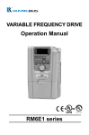
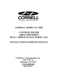
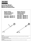
1
RM5 series
FOREWORD
Thank you for choosing the RHYMEBUS " RM5 Series " high-function,
inverter. This instruction manual gives information on installation, wiring,
parameter unit operation, etc. as well as maintenance and inspection
procedures. However, it is essential to read this manual carefully to use
the equipment safely, correctly, and to it's full capability. Please forward
this manual to the end user.
SAFETY PRECAUTIONS
Please read this manual thoroughly prior to installation, wiring, operation,
maintenance and trouble shooting. Also, any statement and symbol
denoted by "DANGER" or "CAUTION" should be read carefully.
DANGER : Indicate dangerous cases that accompany the
possibility of death or serious injury caused by
erroneous handling not in accordance with manual.
CAUTION : Indicates dangerous cases that accompany the
possibility of medium or light injury or material
damage caused by erroneous handling not in
accordance with manual.
* Note : that although
CAUTION indicates
medium or light injury or material damage
can be caused, there is possibility of serious
injury.
Note :
that installation, wiring, operation and trouble shooting can be performed
only by experienced peoples who know the principles, constructions,
properties and operational procedures of inverter, can prevent damages,
and read this manual completely.
INTRODUCTIONS
Features (Software NO. P5102A)
Low noise
High torque
Automatic voltage regulation
User friendly
Restart after instantaneous power interruption.
9 levels for speed setting
6 digits display
Noncontact charge circuit for 7.5~30 HP
Programmable inputs and outputs
Store and copy settings by using KP-201 digital keypad
Connect to the external indicators for displaying the status of inverter
Energy saving
Parameter management systems
Low noise
Using IGBT by which the maximum switching frequency of sinusoidal PWM
is 10kHz to 15kHz, the motor is operated smoothly and efficiently with low noise.
80
dB
Current waveform(at 10Hz)
Ordinary
70
RM5
60
50
40
30
0
Ordinary
inverter
RM5(IGBT)
500
1000
1500 1800
Motor speed( rpm / min)
High torque
At low speed, the torque compensation by which the compensated torque can be
above 150% of rated torque is provided for smooth start in the case of heavy load.
Automatic voltage regulation (AVR)
In spite of the fluctuation of power source, output voltage of inverter can be kept
at the desired level.
User friendly
There are two types of operating keypad, one for advanced applications and the
other for usual use. User can choose one of them to function inverter easily and
properly. Besides, the connector between inverter and keypad is the same as that
of telephone. The remote control is then easily realized with maximum distance
of 25 m.
Restart after instantaneous power interruption
If the power source is shutdown during running, the functions of recording the
speed of motor before power interruption and resuming that after restart are
provided.
Levels for speed setting
There are 5 independent acceleration time settings. Therefore, the maximum and
minimum acceleration times are 0.015 sec. and 192000 sec. (about 22 days),
respectively (excluding free running).
6 digits display
There are 8 status of inverter can be displayed (frequency, speed, voltage, current
, etc).
Noncontact charge circuit for 7.5~30 HP
Prevent inverter from dust and the effect of life of machinery.
Programmable inputs and outputs
There are 13 functions programmed by using input terminals X1~X6 and 12
functions programmed via output terminals, Y1 and Y2 (open collector), and Ta
and Tb (relay output)
Store and copy settings
The settings can be stored in KP-201 and used for the other inverter by means of
plugging KP-201 in inverter. If the KP-201 containing stored settings is plugged
in the other inverter, the copy of the stored settings to the other inverter can be
performed, and the inverters have the same settings. This function is useful in the
case of several inverters with the same data settings.
Connect to the external indicator for displaying the status of inverter
There are 3 external indicators(96cm x 48cm, 5 digits)can be used simultaneously
to indicate the inverter status such as frequency, speed, voltage, current, and line
velocity etc. Therefore, it is not needed to use the other instruments or sensors
such as CT etc., and the cost and wiring will be reduced
Energy saving
Under the no load condition, the less energy is outputted for the purpose of saving
energy.
Parameter management system
The management system is software, which can display the descriptions and
settings of parameters in Chinese or English. The schematics diagram of
management system is shown in the figure below.
Parameter management system of RM5
Parameter settings are stored in inverter.
Parameter settings are stored in digital
keypad.
Parameter settings are stored in
computer.
Parameter settings are printed out for
filing.
PC
Printer
Keypad
RS232
Hz
A
V
PROG
RUN
FUN
STOP
DATA
RESET
KP-201
KP-201
Converter
RM5 series
CONTENTS
CHAPTER 1 INSPECTIONS AT PURCHASE
(1) Confirmation of product
(2) Standard specifications
CHAPTER 2 INSTALLATIONS AND CONFIRMATIONS
(1) Basic setup
(2) Environment
(3) Descriptions of terminals and wiring diagram
CHAPTER 3 TYPES OF KEYPADS
(1) Digital keypad (KP-201)
(2) Analog keypad (KP-202)
CHAPTER 4 OPERATIONS OF KEYPADS
(1) Setting of digital keypad (KP-201)
(2) Settings of analog keypad (KP-202)
CHAPTER 5 LIST OF FUNCTION CODE SETTINGS
CHAPTER 6 DESCRIPTIONS OF FUNCTION CODE SETTINGS
(1) Settings of keypad
(2) Multiple speed level settings
(3) Acc/dec time of multiple speed level
(4) V/F pattern settings
(5) Analog input commands
(6) Upper and lower bound of output frequency
(7) Analog outputs
(8) Settings for motor protection
(9) Multiple function input terminals
(10) Settings of multiple function outputs
(11) Frequency detection
(12) Gain of the torque boost
(13) Settings of overload detection
(14) Settings of stall prevention
(15) DC braking
(16) Resumption after instantaneous power interruption
(17) Jump of frequency
(18) Speed tracking
1
2
4
4
6
14
14
15
20
23
29
32
34
36
38
39
40
41
42
45
49
49
50
51
52
53
54
55
(19) Settings of creep
(20) External indicators
(21) Miscellaneous
(22) Settings of KP-202 analog keypad
CHAPTER 7
OPERATIONAL PROCEDURES, MAINTENENCE, AND
TROUBLE SHOOTING
(1) Operational procedure and operations
(2) Fault, maintenance and trouble shooting
APPENDIX A
(1) Dimensions
(2) Auxiliary control equipment (ACE series)
(3) Dynamic brake and resistor
(4) Selections of motor
(5) Selections of AC reactor (ACL)
APPENDIX B
(1) Remote controllers
(2) Remote indicators
APPENDIX C
DIMENSIONS OF OPENING OF KP-201 AND KP-202
APPENDIX D SETTINGS MEMO
APPENDIX E FAULT DISPLAY
55
56
57
59
61
62
63
66
67
68
69
70
73
74
75
78
CHAPTER 1 INSPECTIONS AT PURCHASE
INVERTER
TYPE
RM5-2007
SOURCE AC 200~230V 50/60Hz
OUTPUT
5.5KW 25A
SERIAL
8021520
RHYMEBUS CORPORATION
8 0 2 1 5 2 0
(1) Confirmation of product
Although this product is under a rigorous quality control, the damages
may be made by impact and vibration etc. during transportation. Upon
unpacking of the inverter at site, please check the follows accordingly.
If there is any defect, contact your local dealer at once.
A. Confirmation of appearance
Is there any damage, filth or distortion to the appearance of inverter?
B. Do the rated capacity and specification shown on nameplate confirm
to your requirements?
Model number
Input power source specifications
Output current & capacity
Serial number
C. Model number scheme:
RM5 - 2 007 B
B Brake type (with internal braking
transistor which is the standard for the
inverter with rated power less than 5 hp.
Brake type is, therefore, not indicated in
the nameplate of the inverter with rated
power less than 5 hp.)
007 Rated power(7.5HP)
2 Indicate 200V/220V/230V
4 Indicate 380V/415V/440V/460V/480V
RM5 RHYMEBUS series number
D. Confirmation of accessories
Generally, there is one user's manual. If there are some accessories,
such as braking resistor etc., are ordered please check inclusively.
E. Please refer to the standard specifications and confirm to your
requirements.
1
2
1
200 2 2001 2002 2003 2005 2007 2010 2015 2020 2025 2030 2040 2050 2060 2075 2100 2125 2150
, 200~230V, 50/60Hz(Up 7.5HP/5.5kw)
5%
180V~253V, 50/60Hz
3
4001 4002 4003 4005 4007 4010 4015 4020 4025 4030 4040 4050 4060 4075 4100 4125 4150 4175 4200 4250 4300
1 /3 ,200~230V,50/60Hz
0.01 ~ 400Hz
Tolerance of power
source voltage
Tolerance of frequency
fluctuation
Power source( , V, HZ)
3
5%
323V~506V, 50/60Hz
, 380 ~ 480V, 50/60Hz
0.01 ~ 400 Hz
Range of output
frequency(Hz)
380 ~ 460V
3
Rated output voltage (V)
Rated power of the motor
1/0.75 2/1.5 3/2.2 5/3.7 7.5/5.5 10/7.5 15/11 20/15 25/18.5 30/22 40/30 50/37 60/45 75/55 100/75 125/90 150/110 175/132 200/160 250/200 300/220
(HP/KW)
Rated continuous output
7 10 14 18 23 30 34 46 56 66 84 104 134 165 193 232 287 316
1.9 3.3 4
power(KVA)
Rated continuous output
2.5 4
6
9 14 18 24 30 39 45 61 73 87 110 137 176 204 253 304 377 415
current(A)
Series No.(RM5)
RM5-400V Series
Tolerance of power
source voltage
Tolerance of frequency
fluctuation
Power source( , V, H Z )
Range of output
frequency(Hz)
Rated power of the motor
0.5/0.4 1/0.75 2/1.5 3/2.2 5/3.7 7.5/5.5 10/7.5 15/11 20/15 25/18.5 30/22 40/30 50/37 60/45 75/55 100/75 125/90 150/110
(HP/KW)
Rated continuous output
55
1.3
3
13
33
6
9
18
28
67
84 115 132 160
4
44
2
22
power(KVA)
Rated continuous output 3
5
33
8
25
46
60
90
115
145
175
220
295 346 405
74
11
17
current(A)
Rated output voltage(V)
3 200 ~ 230V
Series No.(RM5)
RM5-200V Series
~ INSPECTIONS AT PURCHASE ~
(2) Standard specifications
~ INSPECTIONS AT PURCHASE ~
Common specifications
User interface
Digital and analog operating keypads with remote control.
Control characteristics
Sinusoidal PWM control.
Control characteristics
Range of frequency
setting
0.1 ~ 400.00Hz
Resolution of
frequency setting
Resolution of output
frequency
Analog voltage of
frequency setting
Overload current
5 acceleration/
deceleration times
Braking torque
Digital keypad:0.1Hz, Analog keypad: 0.06/60Hz
0.01Hz
DC 0 ~ 10V(20K ), 4 ~ 20mA(250
)
150% rated current for 1 minute.
Zero sec for free running, 0.1 ~ 3200 seconds for each setting,
About 20% (For the inverter rated power less than 10 hp, the braking
transistor is included, and braking torque can be about 100%)
Voltage/Frequency
pattern
The pattern can be set arbitrarily.
Stall prevention
The current of stall prevention can be set arbitrarily
Ambient conditions
Protections
Displays
Input
Output
Operational characteristics
Control of direction of rotation; forward / reverse rotation is controlled by using 3-line sustaining circuit.
Stop command by using the 3-line sustaining circuit, jogging operation,
secondary acceleration/deceleration time, multiple-level speed command 1,
multiple-level speed command 2, multiple-level speed command 3, reset,
Multiple function
command for exceptional conditions, command of inhibiting output,
command of stop via free running, command of frequency search from the
inputs
max. frequency, command of frequency search from the set frequency,
acceleration/deceleration inhibition command, programmable contacts a and b.
Vin-GND (0~10V), Iin-GND (4~20mA)
Analog inputs
Running, constant speed, zero speed, frequency detection, overload
detection., stall prevention, undervoltage, braking, restart after
Multiple function instantaneous power interruption, restart after trouble shooting, exceptional
outputs
conditions, programmable contacts a and b.
Analog outputs
Displays of keypads
Displays of external
indicators
Functions
Diagnostics
Cooling
Environment
Temperature
Storage temperature
Relative humidity
Vibration
Altitude
Analog voltage, DC 0~10 V with adjustable gain, for representing
output frequency, frequency setting, or output current
Output frequency, frequency settings, output voltage, DC voltage,
output current, motor speed, line velocity of motor, status of terminals.
There are 3 external indicators (96cm 48cm, 5 digits) can be used
simultaneously to indicate the frequency, speed, voltage, current,
and line velocity etc.
Overcurrent (OC), over voltage (OE), under voltage (LE),
motor overload (OL), inverter overload (OLI), over heat (OH),
ground fault current(GF), fuse open (SC),
disconnection of KP-202 during running (PadF).
Disconnection of digital keypad (Err_00, Err_01), EEPROM error (Eer)
Force cooling (natural cooling for rated power of 1/2 and 1 Hp)
Non-corrosive non-conductive, or non-explosive gas or liquid, and non-dusty.
-10
(14
) ~+50
(122
-20
(-4
),non-freezing and non-condensing
) ~+60
(149
)
90% RH or less (non-condensing atmosphere)
Less than 5.9m/sec2 (0.6G)
Less than 1000m (3280 ft)
3
CHAPTER 2 INSTALLATIONS AND CONFIRMATIONS
(1) Basic setup
The inverters have to be incorporated with some elementary devices
for driving motor. The essentially elementary devices of basic setup are
A.Power source
The power source should be agreed with the specifications of Inverter.
Nofuse brake (NFB)
The rating of NFB should be greater than the start current.
B.Inverter
This is main device of driving motor. Referring to the lists of
standard specifications of inverter, inverter is chosen in accordance
with the specifications of motor driven.
C.Motor
The specifications of motor are determined from the requirement of
applications.
(2) Environment
For correct and safety operation, the operational environment of
inverter should be cared and described as followings
A.Power source
The power source should be agreed with the specifications of inverter.
B.Location
For the considerations of heat generated by the operating machine,
inverter has to be installed in the ventilative space. The installations
of inverter are shown as followings.
a. The space of installation is good for power dissipation or not.
10cm
or more
5cm or more
5cm or more
10cm
or more
4
~ INSTALLATIONS AND CONFIRMATIONS ~
b. The cooling is needed if the inverter is installed in a protective
case or distributor.
Panel Control Box
fan
RM5
Inverter
Control Heat
circuits sink
fan
Filter
c. If the inverter is installed in a protective case or distributor (suitable
for 7.5~75 hp) and the cooling system is on or outside protective
case or distributor, it should be mentioned that the hole for airflow
is adequate or not.
Panel Control Box
fan
RM5
Inverter
Control
circuits
Heat
sink
fan
Ventilation hole
Filter
d. Specifications of the associated accessories
The specifications of the associated accessories have to be in
accordance with the specifications of inverter used. Otherwise, the
inverter will be damaged and the lifetime of inverter will be
decreased.
5
~ INSTALLATIONS AND CONFIRMATIONS ~
e. Cleaning of environment
The ventilation, cleanliness and moisture of the space in which the
inverter is installed have to be considered.
f. Operator
Only experienced peoples can perform operation and trouble
shooting
(3) Descriptions of terminals and wiring diagram
A. Wiring diagram
Note that the terminals represented by and are denoted for main
and control circuits, respectively.
a. Wiring diagram for 0.5~5 HP
Braking Resistor(option)
Terminals of main circuit
Terminals of control circuit
3 power
sourse
R
(connect to R
S
and S for
single-phase T
power sourse)
PR P
R
S
T
Induction motor
U
V
W
PE
IM
Grounding
Forward
FWD
Reverse
REV
FM+
Multi-function input
terminal 1
Multi-function input
terminal 2
Multi-function input
terminal 3
Multi-function input
terminal 4
Multi-function input
terminal 5
Multi-function input
terminal 6
X1
GND
Analog signal
output
(DC 0~10V)
X2
X3
X4
X5
X6
Ta
Tb
Tc
Multi-function
output terminals
(relay output)
(AC 250V/0.5A
COS =0.3)
COM
12V
VR 1K
1/4W
Vin
Iin
Y1
Multi-function
output terminals
(open collector)
Y2
CME (DC 48V/50mA )
GND
frequency command in voltage
(DC 0~10V)
frequency command in current
(DC 4~20mA)
6
Built-in brake transistor.
~ INSTALLATIONS AND CONFIRMATIONS ~
b. Wiring diagram for 7.5~75 HP
DC Reacter
Terminals of main circuit
Terminals of control circuit
P1 P N
(PR)
3
power sourse
R
S
T
R
S
T
When the DC reactor is used,
disconnect this jumper
IM
Grounding
Forward
FWD
Reverse
REV
FM+
Multi-function input
terminal 1
Multi-function input
terminal 2
Multi-function input
terminal 3
Multi-function input
terminal 4
Multi-function input
terminal 5
Multi-function input
terminal 6
X1
FM-
VR 1K
Induction motor
U
V
W
PE
Analog signal
output
(DC 0~10V)
X2
X3
X4
Ta
X5
Tb
X6
Tc
COM
12V
1/4W
Y1
Vin
Iin
GND
Y2
CME
Multi-function
output terminals
(relay output)
(AC 250V/0.5A
COS =0.3)
Multi-function
output terminals
(open collector)
(DC 48V/50mA )
frequency command in voltage
(DC 0~10V)
frequency command in current
(DC 4~20mA)
In case 7.5~30HP as build-in brake resistor, the mark of P1 will
change to PR.
For the up to 400V 40HP/KW, there are small terminals,
on the right side of RST, UVW, which are
0 380 415 440 460
connected to the wire of cooling fan and contactor. Be sure connect
to the correct required voltage. (Ex. when power is 380V, then must
be connect 0 and 380V. In case the power change to 460V, please
connect to 0 and 460V)
7
~ INSTALLATIONS AND CONFIRMATIONS ~
B. Descriptions of terminals
a. Terminals of main circuit
Main Circuit
Terminals Symbols
Descriptions
Name
Power
source
R.S.T. Input AC voltage
3-phase power source(for 1
R and S only)
Motor
Inverter output
U.V.W. voltage
3-phase variable voltage and frequency
output motor
P.N.
Power PR
and
braking
P1
Grounding PE
Dynamic brake
terminals
External braking
resistor
External reactor
Grounding
, 220V, use
Connect to the dynamic brake unit
P and PR terminals connect to an external
braking resistor(option)
P and P1 terminals are short-circuit or
connect to an external reactor for
improving power factor. The factory setting
is short-circuit.
Less than 100 for the third grounding
method
b. Main circuit
(1) For 1/2~5 HP
Grounding
NFB
Motor
Resistor
(2) For 7.5~10 HP (connect braking resistor)
NFB
Resistor
Grounding
Grounding
8
~ INSTALLATIONS AND CONFIRMATIONS ~
(3) For 15~30 HP (connect braking resistor)
PE
Grounding
terminal
Grounding
NFB
Grounding
Resistor
Motor
*Note:
1. The polarities of P and N terminals should be wired
correctly.
2. For 40~75 hp, the positions of terminals may be
different from those shown in the figure, they are
, however, labeled with the same symbols or
characters. Please wire the system according to the
labels of terminals.
(4) For 7.5~10 HP (connect dynamic braking unit)
NFB
Grounding
ACE-01
D.B.unit
Grounding
R.
S. Power
(5) For 15~30 HP (connect dynamic braking unit)
PE
Grounding
terminal
Jumper
NFB
Grounding
Grounding
Power R.
S.
*Note:
1. The polarities of P and N terminals should be wired
correctly.
2. For 40~75 hp, the positions of terminals may be
different from those shown in the figure, they are,
however, labeled with the same symbols or characters.
Please wire the system according to the labels of
terminals.
9
~ INSTALLATIONS AND CONFIRMATIONS ~
c. Terminals of control circuit
Terminals Symbols
FWD
REV
Name
Multiple function
input terminal 1
Multiple function
X2
input terminal 2
Multiple function
X3
input terminal 3
Multiple function
Input
X4
input terminal 4
terminals
Multiple function
X5
input terminal 5
Multiple function
X6
input terminal 6
Common of input
COM terminals
Control Circuit
X1
Vin
lin
Power
source
Function is determined by F_052
Function is determined by F_053
Function is determined by F_054
Function is determined by F_055
Function is determined by F_056
Function is determined by F_057
Common of input terminal signals
Voltage type of frequency Analog voltage 0~+10 V
command input
Current type of frequency
DC current 4~20mA
command input
Reference voltage 12V reference voltage with maximum
+12V of control signals current 20mA
GND
Ground of control
signals
Ground of control signals
FM+
FM-
Analog output
terminals
DC 0~10 V outputs to voltage-type meter
such as frequency meter or current meter.
For 0.5~5 HP, FM+ and GND are used to
output voltage
Ta
Tb
Output
terminals Tc
Y1
Y2
CME
10
Descriptions
is short-circuit for forward
Forward operation FWD-COM
operation
is short-circuit for reverse
Reverse operation REV-COM
operation
Multiple function
output terminals
(relay outputs)
Multiple function
output terminals
(Open-collector)
The function of contact a(normally open) is
determined by F_60. (The capacity of
contact is 250VAC, 0.5A and cos =0.3)
The function of contact a (normally
close)is determined by F_60. (The capacity
of contact is 250VAC, 0.5A and cos =0.3)
Common terminals of Ta and Tb.
Function is determined by Function is
determined by F_058.
Function is determined by Function is
determined by F_059.
Common of terminals Y1 and Y2
~ INSTALLATIONS AND CONFIRMATIONS ~
C. The notes and specifications of wiring
a. The leakage current between ground and the wires that are
connected between inverter and motor, is not the same for
different rated power. The setting of carry frequency (F_55) is
referred to the table below.
Distance
Rated power
1/2 ~ 5HP
7.5 ~ 10HP
15 ~ 30HP
40 ~ 75HP
100~150HP
10 m
25 m
50 m
100 m
Above 100 m
12.5KHz
or less
10KHz
or less
7.5KHz
or less
5KHz
or less
2.5KHz
or less
10KHz
or less
7.5KHz
or less
5KHz
or less
2.5KHz
or less
2.5KHz
or less
7.5KHz
or less
5KHz
or less
2.5KHz
or less
2.5KHz
or less
2.5KHz
or less
5KHz
or less
2.5KHz
or less
2.5KHz
or less
2.5KHz
or less
2.5KHz
or less
2.5KHz
or less
2.5KHz
or less
2.5KHz
or less
2.5KHz
or less
2.5KHz
or less
Note : That the carry frequency is set by F_081.
b. If the inverter is used where the altitude is greater than 1000 m,
the relationship between current and altitude should be mentioned
and referred to the figure shown below.
100%
90%
Percentage
of the rated
current of
inverter
80%
Altituds
(m)
70%
60%
1.000
2.000
3.000
4.000
11
~ INSTALLATIONS AND CONFIRMATIONS ~
c. Precautions
DANGER
1. If the inverter is powered, the wiring is inhibited.
2. R, S and T terminals, connected to power source, are power input terminals of inverter.
U, V and W terminals, connected to motor, are power output terminals of inverter. The
care that P, N, PI and PR terminals can not be connected to either power source or motor
must be made.
3. After turn off power source, please don't touch the inverter and change the wiring when
indicator is light.
4. The terminals of main power circuit and control circuit can not be connected to PE
terminal.
5. After wiring is completed, please put on the inverter cover for avoiding the other
people's touch.
6. For 200 V series, 346/380/440/460 V power source can not be used.
7. In the restart after instantaneous power interruption, running is resumed and the people
around motor and machinery should be controlled for avoiding danger and damage.
8. The wiring of main circuit and control circuit should be separated for avoiding
interference.
9. Only experienced people can perform installation, wiring, operation and trouble
shooting.
10. The RM5 series are not designed against explosion and then should be kept away from
gas, oil and explosion etc.
CAUTION
1. The RM5 series should be kept away from corrosive gas, oil, dust, high temperature,
elevated humidity and explosion etc.
2. If inverter is installed in a protective case or distributor, the ambient temperature can not
exceed +50 oC.
3. Isolated wires of control signals are recommended, noise and grounding have to be
considered for avoiding interference.
4. Wiring terminals and installation:
(1) Wiring should be made according to the symbols of terminals. Keep terminals
connected tightly with wire.
(2) Appropriate wiring size should be used. Connect R, S and T terminals to power
source (In the case of single phase power source connect R and S terminals to power
source).
(3) Use nofuse brake (NFB), magnetic contact or fuse at power source input terminals,
and use a thermal relay (THRY) to protect motor if the motor capacity is smaller than
inverter.
(4) After U, V and W terminals of motor have been disconnected, the insulation of motor
can be then tested. Note that testing motor and inverter can be performed only by
experienced peoples
12
~ INSTALLATIONS AND CONFIRMATIONS ~
d. Recommended wiring size (for reference only)
MOTOR
(HP)
1
200V Series (mm2)
Main
Control Grounding
circuit
circuit
wire
2
400V Series (mm2)
Main
Control Grounding
circuit
circuit
wire
2
2
2
2
3
2
2
5
3.5
3.5
7.5
5.5
3.5
10
8
5.5
15
14
8
20
22
25
30
30
38
40
60
30
50
80
30
60
100
38
75
60 X 2
60
100
100 X 2
80
125
150 X 2
100
150
200 X 2
60 X 2
0.75
The same
as that of
main circuit
8
14
22
0.75
The same
as that of
main circuit
13
CHAPTER 3 TYPES OF KEYPADS
(1) Digital keypad (KP-201)
1. T.S : Indicator of the
status of terminals .
2. Indicator of unit.
1. If LED is light, speed is
command by keypad.
2. If LED is not light, speed
is command by terminals.
1. Enter function code
setting mode.
2. Back to monitor mode.
1. Constant speed : LED is
light.
2. Acc./dec. : LED flashes.
RPM
MPM
T.S
Inverter begins to output
frequency.
Increase or decrease setting.
1. Enter parameter setting
mode.
2. Back to monitor mode.
1. Inverter stops frequency
output.
2. Reset.
(2) Analog keypad (KP-202)
1. If LED is light, speed is
command by keypad.
2. If LED is not light, speed
is command by terminals.
The LED will be light, if the
corresponding ADJ has been
chosen by RSW.
1. Constant speed : LED is
light.
2. Acc./dec. : LED flashes.
Frequency setting.
Inverter begins to output
frequency.
1. Inverter stops frequency
output.
2. Reset.
14
CHAPTER 4 OPERATIONS OF KEYPADS
(1) Setting of digital keypad
A. Digital keypad has three modes and displays for exceptional
conditions. The switching among these is shown in the setting
diagram below.
Function code
setting mode
Monitor mode
00
PROG
F 00 I
V
A
STOP
FUN
0
DATA
FUN
PROG
Hz
Parameter
setting mode
Hz
V
A
DATA
Hz
V
A
PROG
RESET
PA F
Hz
V
A
Error message
15
~ OPERATIONS OF KEYPADS ~
B. In the monitor mode, there are 8 displays, 1 main display and 7
auxiliary displays, used to indicate the status of inverter. The most
left digit indicates the number of auxiliary display (2~8), and the
most left digit is turned off for indicating main display.
Enter monitor mode
Output frequency
000
Hz
V
Frequency setting
FUN
DATA
A
2 6000
Hz
V
Output voltage
FUN
DATA
A
3 2 200
Hz
FUN
FUN
DATA
8
PN
II
V
voltage
4 3 I00
Monitor mode
A
Hz
V
FUN
FUN
DATA
DATA
7 I 200
Hz
A
DATA
Status of terminals
Hz
V
V
A
Line velocity(MPM)
FUN
DATA
6 I800
Hz
V
A
Speed (RPM)
FUN
DATA
5
Hz
A
68
V
A
Output current
a. Any display can be set to be the main display by F_006.
b. The function that the user defines own main display is convenient
to choose the most important status of inverter as main display for
certain applications. If the keypad has not been operated and the
auxiliary display has been displayed for about 3 minutes, the main
display is shown automatically for user to monitor the most
important status of inverter.
16
~ OPERATIONS OF KEYPADS ~
C. In the function code setting mode, there are 118 function codes
(F_000~F_117) to be set and the setting diagram is shown in the
figure below.
Enter function code setting mode.
F 000
Hz
V
F 00 I
A
Hz
V
F I I7
A
Hz
V
A
D. In the data setting mode, the range of setting is defined in function
code and the setting diagram is shown in the figure below.
F 009
Hz
V
A
FUN
FUN
DATA
DATA
00
Hz
V
A
0I
Hz
V
A
4000
Hz
V
A
The max.setting
The range of data setting of F_009 is 0.0 ~ 400.0 Hz.
17
~ OPERATIONS OF KEYPADS ~
E. In the monitor mode, the frequency command, speed (RPM) and
line velocity (MPM) can be changed. For example, the setting
diagram of changing speed is shown in the figure below.
Speed(RPM)
Change the setting
of speed to 2400 RPM
6 I800
Hz
V
Store the new setting
of speed in EEPROM
of inverter.
Flashing LED denotes
FUN
that the function of
DATA
key is valid.
A
Change the setting
of speed to
1401 RPM
6 I80 3
Hz
V
6 2 400
A
Hz
6 I 79 7
Hz
V
V
A
6 I 40 I
A
Hz
Flashing LED denotes
that the function of
key is valid.
V
A
FUN
DATA
Store the new setting
of speed in EEPROM
of inverter.
a. In the monitor mode,
and
on keypad are used to increase
and decrease speed, respectively.
b. After speed setting, the LED of keypad is flashing with the value
of setting, press
within 5 minutes to store speed setting.
FUN
DATA
18
~ OPERATIONS OF KEYPADS ~
F. Only in the monitor mode, the frequency output can be controlled by
pressing
00
Hz
V
A
RUN
or
STOP
RESET
469
RUN
Hz
V
STOP
RESET
A
G. Copy and resume factory settings
a. The function of copy is defined to store settings in digital keypad
(KP-201) or write settings from digital keypad to inverter.
(1) Store settings in digital keypad
To disconnect digital keypad and press
until that digital
keypad is connected t inverter, the LED of keypad will
display '
' to indicate that the setting is storing in digital
keypad (KP-201).
(2) Write setting from digital keypad to inverter
To disconnect digital keypad and press
until that digital
keypad is connected to inverter, the LED of keypad will
display '
' to indicate that the setting is writing from
digital keypad (KP-201) to inverter.
b. Resume factory settings
To disconnect digital keypad and press
until that digital
keypad is connected to inverter, the LED of keypad will display
'
' to indicate that the factory settings have been resumed.
STOP
RESET
19
~ OPERATIONS OF KEYPADS ~
(2) Settings of analog keypad (KP-202)
A. Descriptions of functions of RSW
RSW
Functions
Output
frequency
Corresponding
VR
Boost voltage
Range
Factory setting
Low voltage(220V):6.0V
High voltage(440V):12.0V
0.5 ~ 5HP 5.0 sec
0.0 ~ 165.0 sec 7.5 ~ 30HP 15.0 sec
above 40HP 30 sec
0.5 ~ 5HP 5.0 sec
0.0 ~ 165.0 sec 7.5 ~ 30HP 15.0 sec
above 40HP 30 sec
0.1 ~ 127.5V
ADJ1
Primary
acceleration time
ADJ2
Primary
deceleration time
ADJ3
Speed level 1
0.0 ~ 120.0 Hz 10.0 Hz
ADJ4
Max. output
frequency
Secondary Acc/Dec
time
Frequency
setting
Indicate
frequency setting
Indicate output
voltage
Indicate DC
voltage
Indicate output
current
Indicate speed of
motor
Indicate line
velocity
Indicate status
of terminals
Indicate status
of DIP
20
0.0 ~ 60.0 Hz
60.0 Hz
ADJ5
ADJ6
0.5 ~ 5HP 5.0 sec
0.0 ~ 165.0 sec 7.5 ~ 30HP 15.0 sec
above 40HP 30 sec
~ OPERATIONS OF KEYPADS ~
a. The function code associated with VR can be changed.
b. The status of terminals and DIP are shown as the figure below.
F IIII
Hz
V
A
DIP4 ON
DIP3 ON
DIP2 ON
DIP1 ON
FWD
REV
X5
X6
E
Hz
V
A
" ON " states of DIP
Ta/Tb
X4
Y2
X2
Y1
X1
X3
States of terminals
F 0000
Hz
V
A
DIP4 OFF
DIP3 OFF
DIP2 OFF
DIP1 OFF
" OFF " states of DIP
B. Descriptions of functions of DIP
No.
Switch DIP
ON
1
1 2 3 4
ON
2
1 2 3 4
ON
3
1 2 3 4
ON
4
1 2 3 4
Functions
Carry
frequency
Descriptions
ON : Carry frequency is 2.5 kHz.
OFF: Don't change the Carry frequency.
Remark
Refer to
P. 59
Selections of
ON : Base frequency at 50Hz.
Base frequency OFF: Don't change frequency.
Refer to
P. 59
ON : Frequency commands is generated by
Selections of
terminals.
frequency setting OFF: Don't change the source of commands.
Refer to
P. 59
Selections of ON : Rotation and direction commands are
generated by terminals.
rotation control OFF: Don't change the source of commands.
Refer to
P. 59
21
~ OPERATIONS OF KEYPADS ~
C. Descriptions of functions of ADJ
Functions
Range
Factory setting
Remark
Boost voltage 0.1 ~ 127.5V
Low voltage(220V) 6.0 V
High voltage(440V) 12.0 V
Refer to
P. 60
Primary
acceleration
time
Primary
deceleration
time
0.5 ~ 5HP
7.5 ~ 30HP
above 40HP
0.5 ~ 5HP
7.5 ~ 30HP
above 40HP
Refer to
P. 60
ADJ1
ADJ2
ADJ3
0.0 ~ 165.0 sec
0.0 ~ 165.0 sec
5 sec
15.0 sec
30 sec
5 sec
15.0 sec
30 sec
Speed level 1 0.0 ~ 120.0 Hz
10.0 Hz
Refer to
P. 60
Max. output
frequency
0.0 ~ 60.0 Hz
60.0 Hz
Refer to
P. 60
Secondary
deceleration
time
0.0 ~ 165.0 sec
0.5 ~ 5HP 5 sec
7.5 ~ 30HP 15.0 sec
above 40HP 30 sec
Refer to
P. 60
ADJ4
ADJ5
ADJ6
22
Refer to
P. 60
CHAPTER 5 LIST OF FUNCTION CODE SETTINGS
Function
Name
F_000
Version of
software
Selections of
F_00 I start
Descriptions
Display the version of software.
Direction command
Start command
FWD and REV terminal
0:
REV terminal
1 : FWD terminal
FWD and REV terminals
2 : Start signal is
FWD and REV terminals are
3 : generated by keypad useless
page
Range of Resolu- Factory No.
setting reference
setting
tion
for detail
P5102A 29
0~3
3
29
0~3
1
30
0,1
0
30
changing
F_004 of
frequency
0,1
1
30
F_005
0,1
1
30
1~8
1
31
command
0: Indicate that the frequency is set by terminals.
Select source 1: Indicate that RPM is set by keypad.
F_002 of speed
setting
F_003
F_006
2: RPM set by keypad.
3: MPM set by keypad.
0: Indicate terminals generate start signal and
Selection of
STOP on keypad is invalid.
validity of STOP 1: Indicate terminals generate start signal and
on keypad
STOP on keypad is valid.
Select function 0: indicate that KP-201 is in monitor mode and that
the frequency setting can not be changed.
1: indicate that KP-201 is in monitor mode and that
the frequency setting can be changed.
for KP-201
Select function 0: indicate that KP-201 is in monitor mode and that the
frequency setting can not be stored automatically.
of storing
frequency
1: indicate that KP-201 is in monitor mode and that the
frequency setting can be stored automatically after 3 minutes.
for KP-201
Select main
Select one of 8 displays as main display.
display of KP-201
F_007 Speed constant Set the value of MPM displayed on keypad.
No. decimal of Set the no. decimal of speed displayed on
F_008 speed
display keypad.
F_009
F_0 i0
F_0 I i
F_0 I2
F_0 i3
F_0 i4
F_0 i5
F_0 I6
F_0 I7
F_0 I8
F_0 I9
F_020
Jog
X3
X2
X1
Main speed
OFF
OFF
OFF
OFF
Speed level 1
OFF
ON
OFF
OFF
Speed level 2
ON
OFF
OFF
OFF
Speed level 3
ON
ON
OFF
OFF
Speed level 4
OFF
OFF
ON
OFF
Speed level 5
OFF
ON
ON
OFF
Speed level 6
ON
OFF
ON
OFF
Speed level 7
ON
ON
OFF
ON
Jog speed
X
X
X
ON
Base freq. of acc/dec The frequency associated with acc/dec time.
0 ~ 500.00 0.01 20.00
0~3
60.00
0.00~400.00 0.01Hz (50.00)
(Re.1)
15.0
0.0~3200.0 0.1s (Re. 5)
sec
34
Primary
The deceleration time of main speed, speed level 4~7, and jog speed. 0.0~3200.0
0.1s
sec
deceleration time
0.0~3200.0 0.1s
sec
F_025
F_026
32
Primary
0.0~3200.0 0.1s
acceleration time The acceleration time of main speed, speed level 4~7, and jog speed.
sec
0.0~3200.0 0.1s
sec
F_024
31
32
32
32
32
32
32
32
32
34
Deceleration time
of speed level 1 Deceleration time of speed level 1
Acceleration time
of speed level 2 Acceleration time of speed level 2
Deceleration time
of speed level 2 Deceleration time of speed level 2
Acceleration time
of speed level 3 Acceleration time of speed level 3
Deceleration time Deceleration time of speed level 3
of speed level 3
F_023
31
10.00
20.00
30.00
0.00
0.00
0.00
0.00
6.00
60.00
0.00~400.00 0.01Hz
0.00~400.00 0.01Hz
0.00~400.00 0.01Hz
0.00~400.00 0.01Hz
0.00~400.00 0.01Hz
0.00~400.00 0.01Hz
0.00~400.00 0.01Hz
0.00~400.00 0.01Hz
0.01~400.00 0.01Hz
Acceleration time Acceleration time of speed level 1
F_02 I of
speed level 1
F_022
0
X means don't care
The color as
0.0~3200.0 0.1s
sec
0.0~3200.0 0.1s
sec
0.0~3200.0 0.1s
sec
means which can be set during operation.
23
~ LIST OF FUNCTION CODE SETTINGS ~
Function
Name
F_027
Secondary
acceleration
time
Secondary
deceleration
time
Setting of
S-curve
acc/dec time
Limitation of
output
voltage
F_028
F_029
F_030
Descriptions
Multiple function-input terminals control the
situation of the determination of secondary
acceleration time.
Multiple function-input terminals control the
situation of the determination of secondary
deceleration time.
Setting of acceleration / deceleration time of
S-curve acceleration / deceleration.
0.0~3200.0
0.1s
sec
15.0
34
0.0~3200.0
0.1s
sec
15.0
34
0.1s
0.0
34
1
36
0.0 ~ 5.0
0: output voltage is not limited.
1: output voltage is limited.
0,1
50.0
output Operational maximum output frequency.
F_03 I Max.
frequency
0.1~400.0 0.1Hz (Re.1),
60.0
36
F_032 Start frequency Start frequency of inverter output frequency.
0.1~10.0Hz 0.1Hz
36
F_033
Output voltage associated with output start
Boost voltage
frequency.
F_034
Base
frequency
The frequency associated with rated voltage in
V/F pattern.
F_035 Base voltage The rated voltage of all V/F pattern.
F_036
F_037
F_038
F_039
F_040
F_04 i
F_042
F_043
F_044
F_045
F_046
F_047
Frequency at the Frequency at the changing point 1 of V/F
changing point
pattern.
1
Voltage at the
changing point Voltage at the changing point 1 of V/F pattern.
1
Frequency at the Frequency at the changing point 2 of V/F
changing point pattern.
2
Voltage at the
changing point Voltage at the changing point 2 of V/F pattern.
2
Proportional gain between analog frequency
Frequency
command gain command and output frequency.
Gain of bias Gain of analog bias frequency.
frequency
F_049
(Re.2)
0.1~50.0V
36
0.0
0.1Hz
~400.0 Hz
0.0
36
0.1V
0.0
36
0.0~
0.1Hz
400.0Hz
0.0
36
0.1V
0.0
36
0.00~2.00 0.01
1.00
38
-1.00~1.00 0.01
0.0
38
1.00
39
0.00
39
0
40
1.00
40
1
41
0
41
0.0~255.0V
0.0~510.0V
0.0~255.0V
0.0~510.0V
Analog output Gain = max. output frequency/output frequency.
or Gain = rated current of inverter/output current. 0.01~2.00 0.01
gain
Overload
0: no overload protection for motor.
0,1
protection
1: overload protection for motor.
selection
0: standard rated time protection for motor.
Relay
0,1
selection
1: short rated time protection for motor.
No-load current According to the spec. of motor.
of motor
0.5
6.0(Re.3)
0.1V
12.0(Re.4)
0.1~100V
0.1
0.1Hz 50.0(Re.1)
60.0(Re.2)
~400.0 Hz
220.0
0.1~255.0V
(Re. 3)
0.1V 380.0
0.1~510.0V
(Re. 4)
Ratio of upper The upper bound of output voltage is defined as
bound of output the percentage of the maximum output frequency. 0.00 ~1.00 0.01
frequency
(1.00 denotes the maximum frequency)
Ratio of lower The lower bound of output voltage is defined as
bound of output the percentage of the maximum output frequency. 0.00 ~1.00 0.01
(1.00 denotes the minimum frequency)
frequency
Selection of 0: analog signal indicates output frequency.
analog output 1: analog signal indicates frequency setting.
0~2
signal
2: analog signal indicates output current.
current According to the spec. of motor.
F_048 Rated
of motor
24
page
Range of Resolu- Factory No.
setting reference
setting
tion
for detail
10%~120%
According
by the inverter 0.1A to the spec.
rated current
Of motor
motor
0 ~ motor 0.1A 1/3rated
rated current
current
36
36
41
41
~ LIST OF FUNCTION CODE SETTINGS ~
Function
F_050
F 05 I
F_052
F_053
F_054
F_055
F_056
F_057
F_058
F_059
F_060
F_06 I
F_062
F_063
F_064
F_065
F_066
Range of
Descriptions
setting
According
to
the
load
condition,
slip
is
-9.9~5.0
Slip compensation
compensated for constant speed.
Hz
No. poles of
Setting of poles of motor for conversion of MPM. 2 ~ 10
motor
Input terminal 0: STOP command with 3-line sustaining circuit.
(X5 contact a, X6 contact b)
X1 setting
1: jog command.
Input terminal 2: switching between the secondary
X2 setting
acceleration and deceleration.
3: multiple speed level 1 command.
Input terminal
4: multiple speed level 2 command 2.
X3 setting
5: multiple speed level 3 command 3.
-12~+12
6: Reset command.
Input terminal
7: External exception command.
X4 setting
8: inhibition command for output.
Input terminal
9: stop in free running.
X5 setting
10: speed search from the maximum frequency.
11: speed search from the setfrequency.
Input terminal
12: inhibition command for acceleration and
X6 setting
deceleration.
10: detection of
Output terminal 1: running detection.
2: constant speed detection.
restart after
Y1 setting
3: zero speed detection.
exceptional
Output terminal 4: frequency detection.
conditions.
Y2 setting
5: overload detection.
11: detection of
6: stall prevention detection.
exceptional -11~+11
7: undervoltage detection.
conditions.
Settings of
output terminals 8: detection of braking.
9: detection of restart after
Ta and Tb
instantaneous power interruption.
Frequency range
for constant
Frequency range for constant speed detection. 0.0~10.0
Hz
speed detection
Frequency
0.0~10.0
Frequency detection range.
detection range
Hz
Level of frequency detection for multiple function 0.0~400.0
Level of freq.
output
terminal.
Hz
detection
Gain of the
According to the load condition, adjust the output
automatic
0.0
~ 3.0
voltage of the certain V/F pattern.
torque boost
Name
Output setting
(OLO)
detection
41
2P
4P
41
3
4
1
42
2
7
6
1
2
45
11
49
0.1Hz
2.0
49
0.1Hz
0.0
49
0.1
1.0
49
0,1
0
50
0,1
0
50
0,1
0
50
1%
160
50
The time interval, in which the output current 0.1~10.0
is greater than the setting of F_068, required
0.1s
sec
for overload detection.
0.1
50
170
51
0: Inverter is still running after that overload has
been detected.
1: Output of inverter is inhibited after that
overload has been detected.
Level of
The setting of level of current for overload
setting(OLO) detection.
Time interval
0.0
2.0
F_068 overload
F_069 for overload
0.1Hz
0.1Hz
Selection of
0: There is no output for overload detection.
overload
detection(OLO) 1: There is output for overload detection.
0: There is output for the condition of constant
Status of
frequency only.
overload
detection(OLO) 1: There is output for any frequency.
F_067 for overload
page
Resolu- Factory No.
setting reference
tion
for detail
30%~200%
by the inverter
rated current
Level of stall
30%~200%
constant speed.
rated current
If stall is occurred at the constant-speed running,
by the inverter 1%
F_070 prevention at the the speed is decreased.
The color as
means which can be set during operation.
25
~ LIST OF FUNCTION CODE SETTINGS ~
Function
F_07 I
F_072
F_073
F_074
F_075
page
Range of Resolu- Factory No.
Descriptions
Name
setting reference
setting tion
for detail
Level of stall
30%~200%
If stall is occurred during acceleration, motor is
prevention
by the inverter 1%
160
51
kept at constant speed.
rated current
during acc.
Acceleration time
0.1
of recovery after Setting of acceleration time of recovery after stall
stall prevention at
~3200.0 0.1s 15.0
51
prevention at the constant speed.
the constant
sec
speed
Deceleration time
0.1
of recovery after Setting of deceleration time of recovery after stall
stall prevention
~3200.0 0.1s 15.0
51
at the constant prevention at the constant speed.
sec
speed
Select function of 0: there is no stall prevention during deceleration.
0,1
stall prevention
1
51
1: there is stall prevention during deceleration.
during dec.
0%~150%
Current of DC Setting of level of current for DC braking setting. by the inverter
1%
50
52
braking
rated current
Time interval of
In stop the required time interval for DC braking 0.0~20.0
0.1s
F_076 DC braking in stop setting.
sec
In start the required time interval for DC braking 0.0~20.0
Time interval of
0.1s
F_077 DC braking in start setting.
sec
of
F_078 Selection
resumption
0: inverter can not be
2: shutdown.
restarted after instantaneous
3: Enable controlled
power interruption.
deceleration stop.
1: inverter will be restarted after
( F_103, F_104, F_105,
instantaneous power interruption. F_106)
Level of power
Level of power source for shutdown.
F_079 source
for shutdown
F_080 Number of restart Number of restart for exceptional conditions.
Carry frequency Note that the higher the setting is, the lower the noise
is. The carry frequency is inversely proportional to the
distance between inverter and motor.
0: Indicate stop via deceleration.
Types of stop 1:
Indicate stop via free running.
F_08 I setting
F_082
F_083
F_084
F_085
F_086
F_087
52
0
53
53
0
57
1~6
4
57
0,1
0
57
0
57
0.1Hz
0.0
54
0.1Hz
0.0
54
0.1Hz
0.0
54
0.1Hz
0 ~ 16
1
0.0
54
0%~200%
of the inverter
rated current
1%
150
55
Time interval for The time interval, with zero output frequency,
0.5 ~ 5.0 0.1s
sec
0.5
55
V/F pattern of In the speed tracking, the setting of percentage
of output voltage obtained from the original V/F
speed tracking pattern.
Fault records Display the last 5 records of faults.
Lock of
F_092 parameters
0:Parameters are changeable. Max. frequency can not over 120.0Hz.
1:parameters are locked. Max. frequency can not over 120.0Hz.
2:Parameters are changeable. Max. frequency can over 120.0Hz.
3:parameters are locked. Max. frequency can over 120.0Hz.
Selection of
0: Indicate that voltage is not regulated automatically.
regulation
1: Indicate that voltage is regulated automatically.
F_093 automatic voltage
26
0.0
Current for
F_089 speed tracking preceding with speed tracking.
F_09 I
52
175.0(Re.3)
130.0~192.0V
230.0~384.0V 0.1V 320.0(Re.4)
0: Indicate that reversal rotation is allowed.
Inhibition of
0,1
reversal rotation 1: Indicate that reversal rotation is not allowed.
Jumping
For avoiding the resonance of machinery, the jump 0.0~400.0
frequency 1 of frequency command is occurred in frequency 1.
Hz
Jumping
For avoiding the resonance of machinery, the jump 0.0~400.0
frequency 2 of frequency command is occurred in frequency 2.
Hz
Jumping
For avoiding the resonance of machinery, the jump 0.0~400.0
frequency 3 of frequency command is occurred in frequency 3.
Hz
Jump of frequency The jump of frequency command in frequency 1, 0.0~25.5Hz
2 and 3.
the current is greater than that for speed
F_088 speed tracking Iftracking,
the output frequency is decreased.
F_090
0~3
0.5
100
55
no_Err
57
0~3
0
57
0,1
1
57
0~100%
1%
~ LIST OF FUNCTION CODE SETTINGS ~
Function
Name
page
Range of Resolu- Factory No.
setting reference
setting
tion
for detail
Descriptions
Selection of the
0: Indicate that there is no overload protection.
of inverter (OLI)
1: Indicate that there is overload protection.
F_094 overload protection
0,1
1
57
Voltage level of
220(Re.3)
range of setting is in accordance with power 190~240V
F_095 power source The
0.1V
57
source.
340~480V
380(Re.4)
The output frequency is accelerated to creeping 0.0~400.0
0.1Hz 0.5
Hz
Time duration The time interval for output frequency to be
0.0~25.5 0.1s
0.0
of creep
sec
accelerated to creeping frequency.
No. external
0(Re.10)
No. external indicator connected to inverter.
0~3
indicator
1
Selection of display Selection of display of external indicator 1
0~8
(Re.11)
of external indicator 1
F_096 Creeping
frequency setting frequency and then is in constant frequency.
F_097
F_098
F_099
Selection of display Selection of display of external indicator 2
F_ i00 of
external indicator 2
F_ i0 I
F_ i02
F_ i03
F_ i04
F_ i05
F_ i06
F_ i07
F_ i08
F_ i09
F_ I i0
F_ I I I
F_ I i2
F_ I i3
F_ I i4
F_ I i5
F_ I i6
Selection of display Selection of display of external indicator 3
of external indicator 3
Selection of energy 0: do not equip energy-saving device.
saving device
1: equip energy-saving device.
Selection of
parameter of ADJ1 Selecting parameter of ADJ1 of KP-202
Selection of
parameter of ADJ2 Selecting parameter of ADJ2 of KP-202
Selection of
parameter of ADJ3 Selecting parameter of ADJ3 of KP-202
Selection of
parameter of ADJ4 Selecting parameter of ADJ4 of KP-202
Selection of
parameter of ADJ5 Selecting parameter of ADJ5 of KP-202
Selection of
parameter of ADJ6 Selecting parameter of ADJ6 of KP-202
Selection of
parameter of DIP1 Selecting parameter of DIP1 of KP-202
Selection of
parameter of DIP2 Selecting parameter of DIP2 of KP-202
Selection of
parameter of DIP3 Selecting parameter of DIP3 of KP-202
Selection of
parameter of DIP4 Selecting parameter of DIP4 of KP-202
Selections of
F_ I i7 resumption of
factory setting
0: useless
1: clear fault records
2: resume the factory settings of 60 Hz
3: resume the factory settings of 50 Hz
4: store settings
5: resume last settings
6: digital keypad(KP-201)
inverter parameters
7: digital keypad(KP-201)
inverter parameters
The color as
55
0~8
2
(Re.11)
0~8
3
(Re.11)
0,1
0
58
3.0
53
Decrease frequency
of deceleration time If power source shutdown, then the frequency = 0.0~20.0 0.1Hz
of shutdown power output frequency - decrease frequency.
source
Deceleration time 1 of Deceleration time when output frequency larger
power source for
than switch frequency(F_106)
shutdown
Deceleration time 2 of Deceleration time when output frequency smaller
power source for
than
switch frequency(F_106)
shutdown
Switch frequency of Frequency setting value of switch the
power source for
deceleration time of speed level 2.
shutdown
55
56
15.0
0.0
0.1s (Re.5)
~3200.0
15.0
0.0
0.1s (Re.5)
~3200.0
53
0.0~400.0 0.1Hz
53
0.0
0 ~ 47
19
0 ~ 47
9
0 ~ 47
10
0 ~ 47
1
0 ~ 47
20
0 ~ 46
17
(Re.12)
0 ~ 15
8
0 ~ 15
5
0 ~ 15
3
0 ~ 15
1
0~7
0
53
59
31
means which can be set during operation.
27
~ LIST OF FUNCTION CODE SETTINGS ~
Remark:
(1) Factory settings for 50 Hz
(2) Factory settings for 60 Hz
(3) Specifications of low voltage
system.
(4) Specifications of high voltage
system.
(5) 0.5~5 hp: 5 sec
7.5~30 hp:15 sec
above 40 hp: 30 sec
(6) It is useless if the setting is zero
(7) Display '
'
(8) It will be recovered after the
reset of inverter.
28
(9) The dynamic braking transistor is
installed.
(10) The setting is zero to denote that there
is no external indicator
(11) The setting is zero to denote that there
is no display.
(12)
: represents contact a (normally
open)
: represents contact b (normally
close)
6. DESCRIPTIONS OF FUNCTION CODE SETTINGS
(1) Settings of keypad
A. F_000 : Version of software
This manual has to be incorporated with software version
P5102A.
B. F_00 I : Select start and direction commands
a. F_00 I =0
(1) FWD and REV control both start and direction commands
(2) FWD and REV are either open or closed simultaneously to
stop running.
Forward running
FWD
Reverse running
REV
COM
b. F_00 I =1
Start control by FWD terminal, Rotation control by REV terminal.
Start / Stop
FWD
Reverse
running
REV
Forward
running
COM
c. F_00 I =2
(1) Keypad generates start command, and FWD and REV
generate direction command.
(2) FWD and REV are either open or closed simultaneously to
stop running.
Forward running
FWD
Reverse running
REV
COM
29
~ DESCRIPTIONS OF FUNCTION CODE SETTINGS ~
d. F_00 I = 3
Start signal is generated by keypad,FWD and REV terminals are
useless, and the running is in the positive direction.
Note : that for F_001=0, 2, if FWD-COM and REV-COM are open
simultaneously, the frequency display in the monitor mode
will display flashed '
', and if FWD-COM and REVCOM are closed simultaneously, the frequency display in the
monitor mode will display flashed '
'.
C. F_002 : Select source of speed setting
a. F_002 = 0
Indicate that the analog terminals (Vin or Iin) set the speed.
(1) range of Vin-GND : 0~10 V
(2) range of Iin-GND : 4~20 mA
Note : that the gain and bias of analog signals are the same as
those set in F_040 and F_041.
b. F_002 = 1
Indicate that the speed is set by keypad.
(1) For KP-201, main speed and the multiple level speeds can be
set, besides, the frequency can be set in the monitor mode.
(2) For KP-202, using knob on the panel sets speed.
c. F_002 = 2
RPM set by keypad.
d. F_002 = 3
MPM set by keypad.
D. F_003 : Selection of validity of STOP on keypad
a. F_003 = 0
Indicate terminals generate start signal and STOP on keypad is
invalid.
b. F_003 = 1
Indicate terminals generate start signal and STOP on keypad is
valid.
E. F_004 : Select function of changing frequency for KP-201
a. F_004 = 0
Indicate that KP-201 is in monitor mode and that the frequency
setting can not be changed.
b. F_004 = 1
Indicate that KP-201 is in monitor mode and that the frequency
setting can be changed.
F. F_005 : Select function of storing frequency for KP-201
a. F_005 = 0
Indicate that KP-201 is in monitor mode, the main speed
setting value can not be stored automatically.
b. F_005 = 1
Indicate that KP-201 is in monitor mode, the main speed
setting value can be stored automatically after 3 minutes later.
30
~ DESCRIPTIONS OF FUNCTION CODE SETTINGS ~
G. F_006: Select main display of KP-201
This function is designed for KP-201. In the monitor mode, there are
8 displays as followings.
1. Output frequency
5. Output current
2. Frequency setting
6. Motor speed (RPM)
3. Output voltage
7. Line velocity (MPM)
4. Voltage of PN
8. Status of terminals
Note : that any display can be set to be the main display, and that if
the keypad has not been operated and the auxiliary display
has been displayed for about 3 minutes, the main display is
shown.
H. F_007: Speed constant
The range of setting is 0~500.00 to set the value of MPM displayed
on keypad Line velocity = speed constant output frequency, which is
the value of MPM, displayed in the monitor mode.
I. F_008: No. decimal of speed display
Increasing the no. decimal to display the monitored signal more
precisely. The range of F_008 is 0~3.
J. F_ I i7: Selections of resumption of factory setting
This function is used to resume the factory settings and store/write
settings between inverter and KP-201.
: Useless
: Clear fault records
: Resume the factory settings of 60 Hz.
: Resume the factory settings of 50 Hz.
: Store settings
: Resume last settings
: Digital keypad (KP-201) inverter parameters
: Digital keypad (KP-201) inverter parameters
Note : that the codes '
' and '
' are functions of copy
to be used for the case of several inverters with the same
settings.
31
~ DESCRIPTIONS OF FUNCTION CODE SETTINGS ~
(2) Multiple speed level settings
A. F_009 : Main speed with range 0.00 ~ 400.00 Hz
B. F_0 i0 : Speed level 1 with range 0.00 ~ 400.00 Hz
C. F_0 I I : Speed level 2 with range 0.00 ~ 400.00 Hz
D. F_0 I2 : Speed level 3 with range 0.00 ~ 400.00 Hz
E. F_0 I3 : Speed level 4 with range 0.00 ~ 400.00 Hz
F. F_0 I4 : Speed level 5 with range 0.00 ~ 400.00 Hz
G. F_0 I5 : Speed level 6 with range 0.00 ~ 400.00 Hz
H. F_0 I6 : Speed level 7 with range 0.00 ~ 400.00 Hz
G. F_0 I7 : Jog speed with range 0.00 ~ 400.00 Hz
a. The corresponding function codes
(1) Acceleration and deceleration time for multiple speed level
(F_018~F_019)
(2) Multiple function input terminal settings (F_052~F_057)
b. Production of multiple speed level
Jog
command
Multiple level Multiple level Multiple level
Command 3 Command 2 Command 1
ON
X
X
X
OFF
OFF
OFF
OFF
OFF
OFF
OFF
ON
OFF
OFF
ON
OFF
OFF
OFF
ON
ON
OFF
ON
OFF
OFF
OFF
ON
OFF
ON
OFF
ON
ON
OFF
OFF
ON
ON
ON
Jog speed
Main speed
Speed level 1
Speed level 2
Speed level 3
Speed level 4
Speed level 5
Speed level 6
Speed level 7
Note:
(1) ' X ' denotes " don't care ".
(2) Jog speed has the highest priority.
(3) Jog speed and multiple speed levels are determined by the status,
ON or OFF, of multiple function input terminals which are
programmed by the settings of the multiple function inputs
(F_051, F_056).
(4) ' ON ' denotes that the contact a (normally open) is shortcircuit and
contact b (normally close) is open. 'OFF' denotes that the contact a
(normally open) is open and contact b (normally close) is
shortcircuited.
32
~ DESCRIPTIONS OF FUNCTION CODE SETTINGS ~
c. Multiple speed level and the associated acc/dec time
Frequency
Primary
acceleration
Acceleration time time
of speed level 3
Acceleration time
of speed level 2
Acceleration time
of speed level 1
Primary
acceleration
time
Main
speed
Speed
level Speed
1
level
2
Speed
level
Speed 6
level
Speed 5
Speed level
4
level
3
Speed
level
7
Primary
deceleration
time
Jog speed
Time
Multiple level
command 1
Multiple level
command 2
Multiple level
command 3
Jog command
Note:
(1) The acceleration/deceleration times of jog speed and speed level
4~7 are the same as those of main speed
(2) In stop if the jog speed command is generated, motor will be
running in jog speed without start command.
(3) Except main speed, the analog inputs (Vin and Iin) are useless for
multiple speed levels.
(4) Acceleration and deceleration times are set in F_018~F_029.
33
~ DESCRIPTIONS OF FUNCTION CODE SETTINGS ~
(3) Acc/dec time of multiple speed level
A. F_0 i8 : Base frequency of acc/dec with range 0.01~400.00 Hz
B. F_0 i9 : Primary acceleration time with range 0.0~3200.0 seconds
C. F_020 : Primary deceleration time with range 0.0~3200.0 seconds
D. F_02 I : Acceleration time of speed level 1 with range 0.0~3200.0
seconds
E. F_022 : Deceleration time of speed level 1 with range 0.0~3200.0
seconds
F. F_023 : Acceleration time of speed level 2 with range 0.0~3200.0
seconds
G. F_024 : Deceleration time of speed level 2 with range 0.0~3200.0
seconds
H. F_025 : Acceleration time of speed level 3 with range 0.0~3200.0
seconds
I. F_026 : Deceleration time of speed level 3 with range 0.0~3200.0
seconds
J. F_027 : Secondary acceleration time with range 0.0~3200.0 seconds
K. F_028 : Secondary deceleration time with range 0.0~3200.0
seconds
L. F_029 : Acc/dec time of Scurve acceleration/deceleration with range
0.0~5.0 seconds
a. Multiple acc/dec times are the time duration in which output
frequency is form 0 to base frequency (F_018).
b. The acceleration/deceleration times of jog speed and speed level
4~7 are the same as those of main speed
c. Secondary acc/dec times have the higher priority. Multiple
function input terminals can be programmed to enable secondary
acc/dec. The timing chart is shown in figure below.
34
~ DESCRIPTIONS OF FUNCTION CODE SETTINGS ~
Output frequency
Switching between the secondary
acc. and dec. and the inhibition
command for acc. and dec.
Secondary
deceleration time
Max. Output
frequency
(F_031)
Primary
deceleration
time
Secondary
acceleration
time
Primary
acceleration
time
Time
F_019
*Switching between the secondary
acc. and dec.(Multiple
function-input terminals)
*Inhibition command for acc. and
dec.(Multiple function-input
terminals)
F_027
F_028
F_020
d. If the stop signal is generated, the command of inhibiting acc/dec
is useless.
Note: that there are 4 types of STOP signal described as followings:
(1) If F_001=0 or 2, FWD and REV are either open or closed
simultaneously.
(2) If F_001=1, FWD is open.
(3) If F_003=1, press STOP.
(4) If start command is generated by keypad, press STOP.
e. The acceleration/deceleration times of S curve acceleration/
deceleration are set for
smooth running, for example, to avoid the drop of object in
transmission line or shock of elevator.
Output frequency
S-curve acceleration / decleration
Frequency
setting
S curve time
Time
35
~ DESCRIPTIONS OF FUNCTION CODE SETTINGS ~
(4) V/F pattern settings
A. F_030 : Limitation of output voltage
a. F_030 = 0
Output voltage is not limited
b. F_030 = 1
Output voltage is limited and can not be greater than the voltage
of V/F pattern.
Output voltage
250V
V/F pattern
20V
10V
Base frequency/40
Base frequency
(F_033)
Output frequency
B. F_03 I : Max. output frequency with range 0.1~400.0 Hz.
C. F_032 : Start frequency with range 0.1~10.0 Hz
D. F_033 : Boost voltage. 0.1~50.0 V for low voltage, and 0.1~100.0 V
for high voltage
E. F_034 : Base frequency with range 0.1~400.0 Hz
F. F_035 : Base voltage. 0.1~255.0 V for low voltage, and 0.1~510.0 V
for high voltage
G. F_036 : frequency, range 0.0~400.0 Hz, at the changing point 1
H. F_037 : Voltage, range 0.1~255.0 V for low voltage and 0.1~510.0 V
for high voltage, at the changing point 1
I. F_038 : frequency, range 0.0~400.0 Hz, at the changing point 2
J. F_039 : Voltage, range 0.1~255.0 V for low voltage and 0.1~510.0 V
for high voltage, at the changing point 2
36
~ DESCRIPTIONS OF FUNCTION CODE SETTINGS ~
The relationship among the settings of F_031~F_039 is shown in the
following figure.
V/F pattern
Voltage
Base voltage
(F_035)
Voltage at the
changing point 1
(F_037)
Boost voltage
(F_033)
Frequency at the
changing point 1
(F_036)
Voltage at the
changing point 2
(F_039)
Start frequency Frequency at the
(F_032)
changing point 2
(F_038)
Base frequency
(F_034)
Output
frequency
Max. Output frequency
(F_031)
Note:
(1) Base voltage start voltage and the voltages at the changing
point 1 and 2.
(2) Base frequency frequency at changing point 2
frequency at changing point 1 start frequency
(3) If frequency at changing point 2 is less than that at changing point
1, frequency at changing point 2 is useless.
(4) If frequencies at changing point 1 and 2 are less than start freq.,
frequencies at changing point 1 and 2 are useless.
37
~ DESCRIPTIONS OF FUNCTION CODE SETTINGS ~
(5) Analog input commands
A. F_040: Frequency command gain with range 0.00~2.00
a. Analog input terminals are Vin-GND (0~10 V) and Iin-GND
(4~20 mA)
b. The maximum frequency setting max. output freq. (F_031) freq.
command gain (F_040) For example, gain of analog bias
frequency=0
Max. output freq.= 60.0 Hz
Frequency command gain= 1.20
Output
voltage
Max. output freq.= 60.0 Hz
Frequency command gain=0.80
Output
voltage
72.0Hz
60.0Hz
48.0Hz
0Hz
10V(20mA)
10V(20mA)
0V(4mA)
8.3V(17.3mA)
0Hz
Analog
command
0V(4mA)
Analog
command
B. F_04 I : Gain of analog bias frequency with range 1.00~1.00
a. Bias freq.= max. output freq. (F_031) gain of bias freq. (F_041)
For example, frequency command gain = 1.0
Max. output freq.= 60.0 Hz
Gain of analog bias frequency =0.05
Max. output freq.= 60.0 Hz
Gain of analog bias frequency =0.05
Output
voltage
Output
voltage
60.0Hz
60.0Hz
Analog
command
3.0Hz
0V(4mA)
10V(20mA)
Analog
command
-3.0Hz
b. frequency setting =
Max. Frequency setting - bias frequency
10V (20mA)
gain of frequency
38
0.5V(4.8mA) 10V(20mA)
0V(4mA)
x analog command input