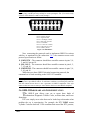
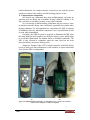
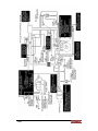
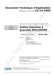
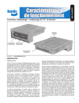
1
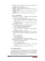
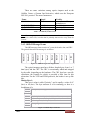
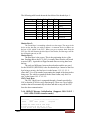
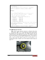
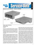
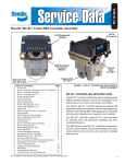
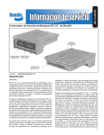
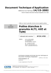
Cairo University Faculty of Engineering Computer Engineering Dept. 4th Year Product Development Automotive On Board Diagnostics OBD-II G21_OBD-II_PD01_v1_0 Prepared By: Group No. 12 Sec. B.N. n o p q \ ] ^ _ Amr Medhat Ahmed Heba Khaled Abd Al‐Azeem Mahmoud Ahmed Genedy Mahmoud Ahmed Yassin Mona Sayed Salem Nesma Ahmed Mostafa Shady Ismail Ahmed Shaima Adel Mahmoud Monitor: Supervisor: OBD‐II 3 4 3 3 4 4 2 2 6 20 22 23 12 19 16 17 Eng. Aly El-gamal Dr. Ra'afat El - Fouly P a g e | 2 TABLE OF CONTENTS: Table of Contents Index of Tables Index of Figures Glossary of Acronyms 1. Preface 1.1. Purpose 1.2. Scope 1.3. Approach 2. Introduction 2.1. What is OBD? 2.2. Why is there a need for OBD? 2.3. Historical Overview of ODB 3. OBD-II Technical Overview 3.1. OBD-II Basic Features 3.2. OBD-II Diagnostic Trouble Codes 3.3. OBD-II Modes of Operation 3.4. OBD-II Standards and Protocols 3.4.1. All Standards 3.4.1.1. SAE Standards 3.4.1.2. ISO Standards 3.4.2. Common Protocols 3.4.3. OBD-II Message Frame 3.4.4. OBD-II Message Initialization 3.5. OBD-II Connectors 3.6. OBD-II Hardware and Implementation 3.7. OBD-II Test Examples 3.7.1. GM Driving Cycle 3.7.2. Ford Motors Company Driving Cycle 4. OBD-II Market and Future 4.1. OBD-II Market 4.1.1. Suggested Market Survey 4.1.2. OBD-II Product Samples in the Market 4.1.2.1. Product 1 4.1.2.2. Product 2 4.1.2.3. Product 3 4.1.2.4. Product 4 4.2. OBD-II Future 5. OBD-II Proposed Project 5.1. Project Objective OBD‐II 3 5 5 6 8 8 8 8 9 9 9 9 13 13 13 15 15 15 15 16 16 17 18 19 20 24 24 25 28 28 28 28 27 28 29 30 31 32 32 P a g e | 3 5.1.1. Hardware 5.1.1.1. OBD-II Interface Card – PCB 5.1.1.2. OBD-II Cable 5.1.1.3. Schematic 5.1.2. Software 6. References OBD‐II 32 32 32 32 33 34 P a g e | 4 INDEX OF TABLES: Table 1-1: OBD Timeline Table 3-1: Common used protocols Table 3-2: Header Byte 1 – Bits[3…0] Function 10 17 18 INDEX OF FIGURES: Figure 3-1: PID Example Figure 3-2: OBD-II Message Frame Organization Figure 3-3: Header Byte 1 Structure Figure 3-4: Example of the DLC location Figure 3-5: OBD-II DLC Figure 3-6: OBD Hardware Examples Figure 3-7: Engine Installed Sensors Figure 5-1: Project Schematic OBD‐II 14 17 17 19 20 22 23 32 P a g e | 5 GLOSSARY OF ACRONYMS: In the order of their appearance in the document Notation Abbreviation OBD On-Board Diagnostics ECU Engine Control Unit MIL Malfunction Indicator Light DTC Diagnostics Trouble Codes EPA Environmental Protection Agency CARB California Air Resources Board DLC Data Link Connector SAE Society of Automotive Engineers LDV Light Duty Vehicles ALDL / ALCL PWM Assembly Line Diagnostics Link / Assembly Line Communications Link Pulse Width Modulation UART Universal Asynchronous Receiver / Transmitter CCM Continuous Current Mode PCM Pulse Code Modulation E-OBD European OBD OBD‐II P a g e | 6 EGR Exhaust Gas Recirculation RPM Revolutions per Minute PID Parameter ID CAN Controller Area Network ISO International Standardization Organization VPW Variable Pulse Width CRC Cyclic Redundancy Check FPGA Field Programmable Gate Array FTP Federal Test Procedure OBD‐II P a g e | 7 PREFACE 1 1.1. PURPOSE This document will try to cover the following issues: ¾ OBD, its importance, versions and standards. ¾ How to Implement an OBD. ¾ OBD in the market. ¾ Future of OBD. 1.2. SCOPE I n this document, we hope to provide an insight into the OBD. We want to get more familiar with car embedded systems that have been widely used since 1996. OBD along with ECU’s become the brain and the immunity system of any new vehicle. We provide here details on the versions of OBD since it was introduced to the car industry. Also, we will have a look on the standards used in the market. An important question will arise, it’s how to implement an OBD this is provided along with a simple market analysis study and the future waiting for OBD. 1.3. APPROACH T his Document starts by providing by introducing the term of OBD to the reader, what it should mean to him in his life, its need & its history in Section 2. In Section 3, we provide the reader with what he needs to get involved in the OBD industry and communication. In our concern with the market potentials and the competitive products we have a look to that in Section 4. Section 5 overviews our proposed project and the suggested circuitry. Eventually, we list the references used to implement this document in Section 6. OBD‐II P a g e | 8 INTRODUCTION 2 2.1. WHAT IS OBD? O n-Board Diagnostic system is a self diagnostic and reporting capability. OBD systems give the vehicle owner or a repair technician access to state of health information for various vehicle subsystems. The amount of diagnostic information available via OBD has varied widely since the introduction in the early 1980s of on-board vehicle computers, which made OBD possible. Early instances of OBD would simply illuminate a Malfunction Indicator Light, MIL, if a problem were detected; however, it would not provide any information as to the nature of the problem. Modern OBD implementations use a standardized fast digital communications port to provide real-time data in addition to a standardized series of Diagnostic Trouble Codes, DTCs, which allow one to rapidly identify and remedy malfunctions within the vehicle. 2.2. WHY IS THERE A NEED FOR OBD? A s higher the level of mobile emissions go, as a higher need for reducing these emissions. Thus, the United States Environmental Protection Agency, EPA, has been charged with reducing mobile emissions from cars and trucks and given the power to require manufacturers to build cars which meet increasingly stiff emissions standards. The manufacturers must further maintain the emission standards of the cars for the useful life of the vehicle. So, here comes the need for OBD to provide a universal inspection and diagnosis method to be sure the car is performing to the required standards. Also, the nice thing about OBD-II, specifically, is that it provides a way to monitor the vehicle health in real time. The data provided by OBD-II can often pinpoint the specific component that has malfunctioned, saving substantial time and cost compared to guess-andreplace repairs. Scanning OBD-II signals can also provide valuable information on the condition of a used car purchase. Note: Two factors will show if your vehicle is definitely OBD-II equipped: 1- There will be an OBD II connector as shown below, and 2- There will be a note on a sticker or nameplate under the hood: "OBD II compliant". 2.3. HISTORICAL OVERVIEW OF OBD T he first widespread use of OBD to monitor emissions control components and parameters was in California in the 1990s. In California, On-Board Diagnostics I, OBD I, was California's first set of OBD regulations that required manufacturers to install OBD systems that monitored some of the emission control components on vehicles. Although OBD‐II P a g e | 9 OBD I systems were required on all 1991 and newer vehicles sold in California, these OBD I systems were not particularly effective because they only monitored a few emission-related components and they were not calibrated to a specific level of emission performance. In addition, the computer software coding and the OBD connection hardware were not standardized. Recognizing the limitations of their OBD I systems, the California Air Resources Board, CARB, developed a new set of OBD standards. A standardized 16-pin Data Link Connector, DLC, with specific pins assigned to specific functions, standardized electronic protocols; standardized Diagnostic Trouble Codes, DTCs, and standardized terminology were outlined. In the USA, the federal government also decided to act in regard to standardizing OBD. The EPA and CARB adopted a number of OBD standards established by the Society of Automotive Engineers, SAE. This new set of federal standards was labeled OBD II. As a result of the federal Clean Air Act Amendments of 1990 in the USA, these newer, more advanced OBD II systems were built into all vehicles manufactured in the United States since 1st January 1996. In the USA, 1996 model year and newer vehicles up to 14,000 pounds are typically equipped with OBD II systems. All 1997 and newer diesel fueled passenger cars and trucks are also required to meet the OBD requirements. In Canada, OBD II became a regulated standard for Light Duty Vehicles, LDVs, for 1998 model year and newer vehicles. We can summarize the evolution phase of the OBD systems even much longer before their appearance in the following table; Year Event ALDL / ALCL: General Motors implements an internal standard for its OBD called the Assembly Line Communications Link, ALCL, later renamed the Assembly Line Diagnostics Link, ALDL. The initial ALCL protocol communicates at 160 baud with Pulse-width modulation, PWM, signaling and monitors very few vehicle systems. This system was only vaguely standardized and suffered from the fact that specifications for the communications link varied from one model to the next. 1982 ALDL was largely used by manufacturers for diagnostics at their dealerships and official maintenance facilities. There were at least three different connectors used with ALDL. General Motors implemented both a 5-pin connector and a 12pin connector, with the 12 pin connector being used in the vast majority of GM cars, while Lotus implemented a 10-pin connector. The pins are given letter designations in the following layouts (as seen from the front of the vehicle connector): • 12-pin ALDL connector pinout: OBD‐II P a g e | 10 FEDCBA GHJKLM • 10-pin ALDL connector pinout: ABCDE KJHGF • 5-pin ALDL connector pinout: ABCDE Unfortunately, the definition of which signals were present on each pin varied between vehicle models. There were generally only three pins used for basic ALDL —ground, battery voltage, and a single line for data—, although other pins were often used for additional vehicle-specific diagnostic information and control interfaces. No battery voltage is present in the 12 pin ALDL connector. An upgraded version of the ALDL protocol appears which 1986 communicates at 8192 baud with half-duplex UART signaling. OBD – I: CARB requires that all new vehicles sold in California starting in manufacturer's year 1988 have some basic OBD capability. The requirements they specify are generally referred to as the OBD-I standard, though this name is not applied until the introduction of OBD-II. The data link connector and its position are not standardized, nor is the data protocol. The regulatory intent of OBD-I was to encourage automobiles manufacturers to design reliable emission control systems that remain effective for the vehicle's "useful life". 1987 The hope was that by forcing annual emissions testing for California, and denying registration to vehicles that did not pass, drivers would tend to purchase vehicles that would more reliably pass the test. Along these lines, OBD-I was largely unsuccessful—the means of reporting emissions-specific diagnostic information was not standardized. Technical difficulties with obtaining standardized and reliable emissions information from all vehicles led to an inability to effectively implement the annual testing program. OBD – I.5: "OBD 1.5" is a slang term referring to a partial implementation of OBD-II which GM used on some vehicles in 1994 and 1995 (GM did not use the term OBD 1.5 in the documentation for these vehicles - they simply have an OBD and an OBD-II section in the service manual). Depending on the year and the vehicle, a car with the OBD 1.5 1994 system may have either the older OBD-I connector, or the newer OBD-II connector, but they are electrically identical to each other. For example, the 94-95 Corvettes have one post-cat oxygen sensor (although they have two catalytic converters), and have a subset of the OBD-II codes implemented. The pinout for the ALDL connection on these cars is as follows: OBD‐II P a g e | 11 9 2 3 4 5 6 7 8 9 10 11 12 13 14 15 16 For ALDL connections, pin 9 is the data stream, pins 4 and 5 are ground and pin 16 is battery voltage. Additional vehicle-specific diagnostic and control circuits are available on this connector. For instance, on the Corvette there are interfaces for the Class 2 serial data stream from the PCM, the CCM diagnostic terminal, the radio data stream, the airbag system, the selective ride control system, the low tire pressure warning system and the passive keyless entry system. An OBD1.5 has also been used on Mitsubishi cars of '95 '97 vintage. Motivated by a desire for a state-wide emissions testing program, the CARB issues the OBD-II specification and mandates that it 1994 be adopted for all cars sold in California starting in model year 1996. The DTCs and connector suggested by the SAE are incorporated into this specification. OBD – II: OBD-II is an improvement over OBD-I in both capability and standardization. The OBD-II standard specifies the type of diagnostic connector and its pinout, the electrical signaling protocols available, and the messaging format. It also provides a candidate list of vehicle parameters to monitor 1996 along with how to encode the data for each. Finally, the OBD-II standard provides an extensible list of DTCs. As a result of this standardization, a single device can query the on-board computer(s) in any vehicle. This simplification of reporting diagnostic data led the feasibility of the comprehensive emissions testing program envisioned by the CARB. The European Union makes EOBD, a variant of OBD-II, 2001 mandatory for all petrol vehicles sold in the European Union, starting in model year 2001 Table 1-1: OBD Timeline OBD‐II P a g e | 12 OBD-II TECHNICAL OVERVIEW 3 3.1. OBD-II BASIC FEATURES W hen a problem that could cause a substantial increase in air emissions is detected, the OBD II system turns on a dashboard warning light, the Malfunction Indicator Light, MIL, to alert the driver of the need to have the vehicle checked by a repair technician. A repair technician can then ascertain the status of various vehicle systems by connecting a 'scan tool' to the standardized connector, the Diagnostic or Data Link Connector. In general, three pieces of information can be downloaded from a vehicle's OBD II system with a 'scan tool': Whether the emissions Malfunction Indicator Light (MIL) commanded 'on' or 'off'. Which, if any, manufacturer fault codes or Diagnostic Trouble Codes are stored (i.e. have been activated). The status of the Readiness Monitors. The current OBD II systems monitor the status of up to 11 emission control related subsystems by performing either continuous or periodic functional tests of specific components and vehicle conditions. The three categories monitored on a 'continuous' basis are misfire, fuel trim and comprehensive components. The remaining eight subsystems are only monitored after a certain set of conditions have been met, or periodically. The algorithms for running these eight, 'periodic' monitors are unique to each manufacturer and involve such things as ambient temperature as well as driving conditions. Most vehicles will have at least five of the eight monitors & the final three systems are not necessarily applicable to all vehicles: • Catalyst. • Evaporative system or leak check. • Oxygen sensor. • Heated oxygen sensor. • Exhaust Gas Recirculation, EGR, system. • Air conditioning. • Secondary air. • Heated catalyst. 3.2. OBD-II DIAGNOSTIC TROUBLE CODES W hen the OBD II computer detects a problem, it sets and stores a Diagnostic Trouble Code or Fault Code. When a car is taken in for diagnosis or for an annual emissions inspection, the repair technician retrieves any set Diagnostic Trouble Codes or fault codes from a vehicle's computer using the 'scan tool'. There are now over 400 possible trouble OBD‐II P a g e | 13 codes that can be stored in the OBD II system. Other manufacturer specific codes may also set by the OBD II system. A standard set of DTCs is available on all vehicles, but each manufacturer includes hundreds of proprietary codes that help pinpoint malfunctions on a specific vehicle. Real-time data sent through the OBD port includes vehicle speed, RPMs, air temperature, and the readings of various sensors. Now this introduces us to a new term Parameter IDs, PIDs, that are codes used to requests data from a vehicle, used as a diagnostic tool. Typically, a car mechanic will use PIDs with a scan tool connected to the vehicle's OBD-II connector. The Event Flow as: • The mechanic enters the PID. • The scan tool sends to the vehicle's CAN bus. • A device on the bus recognizes the PID as one it is responsible for, and reports the value for that PID to the CAN Bus. • The scan tool reads the response, and shows it to the mechanic. An example of a PID & how to translate it is shown in figure 3-1. Figure 3-1: PID example Note: Controller Area Network, CAN, is a communication system whereby multiple nodes connect to and communicate over a bus. The CAN bus may be used in vehicles to connect engine control unit and transmission, or (on a different bus) to connect the door locks, climate control, seat control, etc. Today the CAN bus is also used as a field bus in general automation environments: this is especially because of the cheap prices of some CAN Controllers and processors. The CAN standard is newly emerging. It will be required on all new vehicles by 2008, and it will help various computer systems within your car to communicate. For example, your GPS system could talk to your OBD system or your DVD player. OBD‐II P a g e | 14 3.3. OBD-II MODES OF OPERATION are nine modes of operation described in the OBD-II standard There (SAE J1979). They are: Mode 1: This mode contains a large number of well defined data items. Examples are vehicle speed, RPM, Fuel system status, O2 Sensor voltages, temperatures, timing, etc. Mode 2: This mode retrieves "Freeze frame data". This data is a subset of the items in mode 1, but was stored at some point in the past when a trouble code was set. Mode 3: This mode retrieves powertrain trouble codes, also known as P codes. Mode 4: This mode clears trouble codes (It also clears all other stored diagnostic data, such as freeze frames and on board test results. Mode 5: This mode retrieves the results of Oxygen sensor tests for some vehicles. Mode 6: This mode is used by some vehicles to report non-continuously monitored test results. Mode 7: This mode reports the results of continuously monitored test results. It uses the same format as trouble codes, but the information is available after a single driving cycle. Mode 8: This mode was intended to request control of on board devices. Very little has been generically defined. Mode 9: This mode reports information such as the vehicle's VIN number, and calibration constants. Note that modes 1 and 2 are basically identical, except that Mode 1 provides current information, whereas Mode 2 provides a snapshot of the same data taken at the point when the last diagnostic trouble code was set. The exceptions are PID 01, which is only available in Mode 1, and PID 02, which is only available in Mode 2. If Mode 2 PID 02 returns zero, then there is no snapshot and all other Mode 2 data is meaningless. 3.4. OBD-II STANDARDS AND PROTOCOLS 3.4.1. All Standards 3.4.1.1. SAE Standards J1962 - Defines the physical connector used for the OBD-II interface. J1850 - Defines a serial data protocol. There are 2 variants- 10.4 Kbit/s (single wire, VPW) and 41.6 Kbit/s (2 wire, PWM). Mainly used by US manufacturers, also known as PCI (Chrysler, 10.4K), Class 2 (GM, 10.4K), and SCP (Ford, 41.6K). J1978 - Defines minimal operating standards for OBD-II scan tools. J1979 - Defines standards for diagnostic test modes. J2012 - Defines standards trouble codes and definitions. OBD‐II P a g e | 15 J2178-1 - Defines standards for network message header formats and physical address assignments. J2178-2 - Gives data parameter definitions. J2178-3 - Defines standards for network message frame IDs for single byte headers. J2178-4 - Defines standards for network messages with three byte headers. J2284-3 - Defines 500K CAN Physical and Data Link Layer. 3.4.1.2. ISO Standards ISO 9141: Road vehicles — Diagnostic systems. International Organization for Standardization, 1989. o Part 1: Requirements for interchange of digital information. o Part 2: CARB requirements for interchange of digital information. o Part 3: Verification of the communication between vehicle and OBD II scan tool. ISO 11898: Road vehicles — Controller area network (CAN). International Organization for Standardization, 2003. o Part 1: Data link layer and physical signaling. o Part 2: High-speed medium access unit. o Part 3: Low-speed, fault-tolerant, medium-dependent interface. o Part 4: Time-triggered communication. ISO 14230: Road vehicles — Diagnostic systems — Keyword Protocol 2000, International Organization for Standardization, 1999. o Part 1: Physical layer. o Part 2: Data link layer. o Part 3: Application layer. o Part 4: Requirements for emission-related systems. ISO 15765: Road vehicles — Diagnostics on CAN. International Organization for Standardization, 2004. o Part 1: General information. o Part 2: Network layer services. o Part 3: Implementation of unified diagnostic services (UDS on CAN). o Part 4: Requirements for emissions-related systems. 3.4.2. Common Protocols Within the OBD II standard, there are several protocols for transferring data from the car to a diagnostic device. As a rule of thumb, GM cars and light trucks use SAE J1850 VPW. Chrysler products and all European and most Asian imports use ISO 9141 circuitry. Fords use SAE J1850 PWM communication patterns. OBD‐II P a g e | 16 There are some variations among captive imports such as the Cadillac Catera, a German Opel derivative, which uses the European ISO 9141 protocol. The most common are: Name Speed Used by ISO 9141 10 Kbits/sec SAE J1850 PWM SAE J1850 VPW CAN 100 Kbits/sec 100 Kbits/sec varies by application most Asian and European manufacturers Ford, Mazda primarily GM newer vehicles Table 3-1: Commonly Used Protocols Note: When shopping for an OBD tool, one need to make sure it supports the protocol his vehicle uses, but after that he probably don't need to worry about the protocol. 3.4.3. OBD-II Message Frame CRC Data 7 Data 6 Data 5 Data 4 Data 3 Data 2 Data 1 Header 3 Header 2 Header 1 The OBD message frame consists of 3 parts, the header, data, and CRC. The general format for the message is as follows: Figure 3-2: OBD Message Frame Organization The typical message must have all three header bytes, from 1 to 7 data bytes, and the CRC. The CRC is occasionally added and stripped by the cable, depending on the hardware. The CRC byte has a specific calculation, the formula for which is provided a little later on this subsection. For the VPW and PWM protocols, the header is set up like this: Header Byte 1: This byte is what is called "priority", and is usually a value of 6C (hex) or 68 (hex). The byte structure is a bit confusing, so here is a breakdown of it: Bit 7 Bit 6 Bit 5 Bit 4 Bit 3 Bit 2 Bit 1 Bit 0 Priority Bits, 000 = high, 111= low Header Style, 0 = 3-byte header GM, 1 = Unknown In-Frame Response, 0 = Required Ford, 1 = Not Allowed GM Addressing Mode, 1 = Physical, 0 = Functional Message Type Figure 3-3: Header Byte 1 Structure OBD‐II P a g e | 17 The following table breaks down the last 4 bits of the header byte 1: Addressing Functional Physical Bit 3 Bit 2 Bit 1 Bit 0 1 1 1 1 1 1 1 1 0 0 0 0 1 1 1 1 0 0 1 1 0 0 1 1 0 1 0 1 0 1 0 1 Function Broadcast Query Read Node-To-Node Reserved Reserved Reserved Table 3-2: Header Byte 1 – Bits [3...0] Functions Header Byte 2: The second byte is something referred to as the target. The target is the device on the bus that you wish to address. A common device to address on the bus is $10, which is the ECU. When you get a response back from the ECU, the $10 will become the third byte in the header, and the target will be the off-board scan tool, or $F1. Header Byte 3: The third byte is the source. This is the originating device of the data. Sending data to the ECU ($10), is usually done from the off-board scan tool ($F1). Again this is flipped around when receiving data from the bus. The only real difference between those headers and the one used for the ISO14230 (KWP2000) is the first header byte. Instead of the first byte being a priority, the first byte is in the format 1 1 L L L L L L, where the L's is a 6 bit number representing the length of the data packet being sent. The vehicle responds with the same format, only bit 6 is a zero, in the format 1 0 L L L L L L. CRC Check Byte: The CRC check byte is computed through a formula provided by SAE so that the PCM can verify data integrity. There are a lot of cables out there that will automatically calculate and add or strip off the CRC from the data communication. 3.4.4. OBD-II Message Initialization (Supports ISO 9141-2 / ISO 14230-2 K-line transfer mode) Fastinit: _________ 300ms _____ ____ ____ \_____/ \/\/\/\/ \/\/\/\/ 25ms 25ms packet response 1) Wait for 300ms with K line high. 2) Pull K line low for 25 +/- 1 ms 3) Let K line rise high and wait 25ms OBD‐II P a g e | 18 4) init serial connection to 10400 baud, 8N1, 1=0Volt 0=12Volt, least significant bit first 5) send package 6) wait for response 83 f1 01 c1 e9 8f ae 01=physical address, c1=response ok (7f=fail), e9=kb1, 8f=kb2 Slowinit: _________ S ___ 2 3 ___ 6 7 ___ ____ ____ \_/0 1\___/4 5\___/P \/\/\/\/ \/\/\/\/ 300ms 200 400 400 400 400 250 packet response 1) Wait for 300ms with K line high. 2) send a byte 33 hex at 5 baud. 200ms per bit startbit: 200ms low databit0,1: 400ms high databit2,3: 400ms low databit4,5: 400ms high databit6,7: 400ms low stopbit+pause: 250ms high 4) init serial connection to 10400 baud, 8N1, 1=0Volt 0=12Volt, least significant bit first 5) send package c1 33 f1 81 66 33=dest, f1=our tester id, 81=start comms 6) wait for response 83 f1 01 c1 e9 8f ae 01=physical address, c1=response ok (7f=fail), e9=kb1, 8f=kb2 3.5. OBD-II CONNECTORS T he OBD II port's physical connector is called the Data Link Connector, DLC. It is a 16-pin plug that's usually located under the dashboard near the steering wheel. The standard specifies that the connector must be within three feet of the driver. The connector is located near the hood release in a difficult-to-photograph position. This is shown is figure 3-4. One of the pins on the OBD II connector is power from the car's battery, which means that OBD II readers do not need batteries or an external power source. Another view to the connector itself is shown in figure 3-5. Figure 3-4: Example of the DLC location OBD‐II P a g e | 19 Note: When searching for your DLC, remember that a three-foot sphere around the driver is pretty large, and the port may actually be on the passenger's side. (You can be fairly certain it will be hard to see and/or reach, though.) Pin 2 - J1850 Bus+ Pin 4 - Chassis Ground Pin 5 - Signal Ground Pin 6 - CAN High (J-2284) Pin 7 - ISO 9141-2 K Line Pin 10 - J1850 Bus Pin 14 - CAN Low (J-2284) Pin 15 - ISO 9141-2 L Line Pin 16 - Battery Power Figure 3-5: OBD-II DLC Now, concerning the protocols used to implement OBD-II in various vehicles, as mentioned in the subsection 3.4.2, the connector meets each protocol specification as follow: J1850 VPW - The connector should have metallic contacts in pins 2, 4, 5, and 16, but not 10. ISO 9141-2 - The connector should have metallic contacts in pins 4, 5, 7, 15, and 16. J1850 PWM - The connector should have metallic contacts in pins 2, 4, 5, 10, and 16. While there are three OBD-II electrical connection protocols, the command set is fixed according to the SAE J1979 standard. Note: If your vehicle has this style connector, but doesn't have these pins populated, you probably have a pre-OBD-II vehicle. To add some confusion, even having the connector with the contacts shown above is not a guarantee of OBD II compliance. This style connector has been seen on some pre-1996 vehicles which were not OBD II compliant. 3.6. OBD-II HARDWARE AND IMPLEMENTATION T he OBD-II port allows your car to report three kinds of information: Diagnostic Trouble Codes, real-time data, and freeze frame data. DTCs are simply error codes that can be looked up to determine what problem the car is experiencing. For example, the DTC P0302 means "cylinder 2 misfire detected". If the condition that caused the DTC persists, OBD‐II P a g e | 20 the car's computer will turn on the malfunction indicator light. DTCs are fully explained in subsection 3.2. Real-time data is the raw sensor data reported to the OBD computer. This data can be helpful for troubleshooting problems and monitoring engine performance. Freeze frame data is a snapshot of the real-time sensor feeds at the time of a DTC condition. An auto mechanic can use this data to figure out what was going on at the time your car's "check engine" light went on. OBD II hardware breaks down into two categories: stand-alone devices that are intended exclusively for diagnostics, and signal conversion tools that provide a physical connection, but require software on a computer or PDA to display the data. Obviously the conversion tools will be slightly cheaper, because they are only interfacing to the vehicle and have no processor or memory. They're also more flexible, because the software can be replaced or modified. In the stand-alone devices, the PDA or the computer can be replaced by a microcontroller or a FPGA. Thus, you develop the code to work under a specific protocol or protocols then you burn your code to the programmable device and connect it to the car. In that case we can gain the advantages of a flexible system as the software of the FPGA or the microcontroller is easy to update, while we are enjoying the advantages of a fast & reliable hardware. An example for the above is provided in figure 36(a) for the former and figure 3-7(b) for the latter. The components and systems monitored by the OBD-II system can be divided into two general types: Major monitors It consists of the misfire, catalyst, oxygen sensor, exhaust gas recirculation (EGR), secondary air, evaporative leak check, and fuel systems. These monitors are required to detect malfunctions and illuminate the MIL generally before emissions exceed 1.5 times the applicable Federal Test Procedure, FTP, standards. The FTP is a special laboratory test that is required to be conducted by auto manufactures to show their vehicles comply with emission regulations before they are allowed for sale in California. The test simulates city driving after the vehicle has been parked overnight. The majority of OBD-II monitors (e.g., all the individual sensors, valves, solenoids, etc.) fall under the "comprehensive components" category. This category consists of input or output components that can cause an emission increase or are used to monitor any other monitored components/systems (e.g., the major monitors). A general look for these sensor and components is provided in the next page figure 3-7. For example, if the catalyst monitor is designed to run only when the vehicle is within a certain vehicle speed range, the vehicle speed sensor needs to be monitored. If it wasn't monitored, the vehicle speed sensor OBD‐II P a g e | 21 could malfunction, the catalyst monitor would never run, and the system would never know if the catalyst was still working properly or not. Comprehensive components also include any component that, when malfunctioning, can cause an emission increase during any reasonable driving condition, whether it be idle, cold start, acceleration, cruising, or any other condition. So, even though a malfunctioning component may not seem to cause an emission increase during some conditions, it probably does under other driving conditions. For all comprehensive components, the MIL is required to illuminate when any individual component is out of specification or fails to work when commanded. Generally, the OBD-II system is required to illuminate the MIL after the same fault has been found in two different driving cycles, which helps to ovoid MIL illumination for random faults or abnormal conditions. The MIL is only allowed to extinguish when the same fault has not been detected on three successive driving cycles. Diagnostic Trouble Codes (DTCs) remain stored for around 40 driving cycles to make sure that information is still available to repair technicians even after the MIL is extinguished. (a) (b) Figure 3-6: OBD-II Hardware Examples. (a) stand-alone device, (b) converter card to be connected to a computer or a PDA for diagnosis OBD‐II P a g e | 22 Figure 3-7: Engine Installed Sensors OBD‐II P a g e | 23 3.7. OBD-II TEST EXAMPLES I n the following subsection we provide an example of two Driving Cycle examples. Driving Cycle is a series of data points representing the speed of the vehicle besides some other parameters versus time. It’s produced by different countries and organizations to assess the performance of vehicles in various ways, as for example fuel consumption and polluting emissions. These driving cycles are done here to view the data provided by the OBD-II system. 3.7.1. GM Driving Cycle A complete driving cycle should perform diagnostics on all systems. A complete driving cycle can be done in less than fifteen minutes. To perform an OBD-II Driving cycle does the following: Cold Start. In order to be classified as a cold start the engine coolant temperature must be below 50°C (122°F) and within 6°C (11°F) of the ambient air temperature at startup. Do not leave the key on prior to the cold start or the heated oxygen sensor diagnostic may not run. Idle. The engine must be run for two and a half minutes with the air conditioner on and rear defroster on. The more electrical load you can apply the better. This will test the O2 heater, Passive Air, Purge "No Flow", Misfire and if closed loop is achieved, Fuel Trim. Accelerate. Turn off the air conditioner and all the other loads and apply half throttle until 88km/hr (55mph) is reached. During this time the Misfire, Fuel Trim, and Purge Flow diagnostics will be performed. Hold Steady Speed. Hold a steady speed of 88km/hr (55mph) for 3 minutes. During this time the O2 response, air Intrusive, EGR, Purge, Misfire, and Fuel Trim diagnostics will be performed. Decelerate. Let off the accelerator pedal. Do not shift, touch the brake or clutch. It is important to let the vehicle coast along gradually slowing down to 32km/hr (20 mph). During this time the EGR, Purge and Fuel Trim diagnostics will be performed. Accelerate. Accelerate at 3/4 throttle until 88-96 km/hr (55-60mph). This will perform the same diagnostics as in step 3. Hold Steady Speed. Hold a steady speed of 88km/hr (55mph) for five minutes. During this time, in addition to the diagnostics performed in step 4, the catalyst monitor diagnostics will be performed. If the catalyst is marginal or the battery has been disconnected, it may take 5 complete driving cycles to determine the state of the catalyst. Decelerate. This will perform the same diagnostics as in step 5. Again, don't press the clutch or brakes or shift gears. OBD‐II P a g e | 24 3.7.2. Ford Motor Company Driving Cycle The following procedure is designed to execute and complete the OBD-II monitors and to clear the Ford P1000, I/M readiness code. To complete a specific monitor for repair verification, follow steps 1 through 4, and then continue with the step described by the appropriate monitor found under the "OBD-II Monitor Exercised" column. When the ambient air temperature is outside 4.4 to 37.8°C (40 to 100° F), or the altitude is above 2438 meters (8000 feet), the EVAP monitor will not run. If the P1000 code must be cleared in these conditions, the PCM must detect them once (twice on some applications) before the EVAP monitor can be "bypassed" and the P1000 cleared. The EVAP "bypassing" procedure is described in the following drive cycle. The OBD-II Drive Cycle will be performed using a scan tool. Drive Cycle Recommendations: Most OBD-II monitors will complete more readily using a "steady foot" driving style during cruise or acceleration modes. Operating the throttle in a "smooth" fashion will minimize the time required for monitor completion. Fuel tank level should be between 1/2 and 3/4 fill with 3/4 fill being the most desirable. The Evaporative Monitor can only operate during the first 30 minutes of engine operation. When executing the procedure for this monitor, stay in part throttle mode and drive in a smooth fashion to minimize "fuel slosh". For best results, follow each of the following steps as accurately as possible: OBD-II Monitor Exercised Drive Cycle Preparation Drive Cycle Procedure Purpose of Drive Cycle Procedure 1. Install scan tool. Turn key on with the Bypasses engine soak engine off. Cycle key off, then on. Select timer. Resets OBD-II appropriate Vehicle & Engine qualifier. Clear Monitor status. all DTC's/ Perform a PCM Reset. 2. Begin to monitor the following PIDs: ECT, EVAPDC, FLI (if available) and TP MODE. Start vehicle WITHOUT returning to Key Off. Prep for Monitor Entry HEGO EVAP OBD‐II 3. Idle vehicle for 15 seconds. Drive at 64 Km/h (40 MPH) until ECT is at least 76.7°C (170° F). 4. Is IAT within 4.4 to 37.8°C (40 to 100° F)? If Not, complete the following steps but, note that step 14 will be required to "bypass " the Evap monitor and clear the P1000. 5. Cruise at 64 Km/h (40 MPH) for up to 4 minutes. 6. Cruise at 72 to 104 Km/h (45 to 65 MPH) Engine warm-up and provide IAT input to the PCM. Executes the HEGO monitor. Executes the EVAP P a g e | 25 for 10 minutes (avoid sharp turns and hills) Note, to initiate the monitor: TP MODE should =PT, EVAPDC must be >75%, and FLI must be between 15 and 85% Catalyst 7. Drive in stop and go traffic conditions. Include five different constant cruise speeds, ranging from 40 to 72 Km/h (25 to 45 MPH) over a 10 minute period. EGR 8. From a stop, accelerate to 72 Km/h (45 MPH) at 1/2 to 3/4 throttle. Repeat 3 times. SEC AIR/CCM 9. Bring the vehicle to a stop. Idle with (Engine) transmission in drive (neutral for M/T) for 2 minutes. CCM (Trans) 10. For M/T, accelerate from 0 to 80 Km/h (o to 50 MPH), continue to step 11. For A/T, from a stop and in overdrive, moderately accelerate to 80 Km/h (50 MPH) and cruise for at least 15 seconds. Stop vehicle and repeat without overdrive to 64 Km/h (40 MPH) cruising for at least 30 seconds. While at 64 Km/h (40 MPH) , activate overdrive and accelerate to 80 Km/h (50 MPH) and cruise for at least 15 seconds. Stop for at least 20 seconds and repeat step 10 five times. Misfire & Fuel 11. From a stop, accelerate to 104 Km/h (65 Monitors MPH). Decelerate at closed throttle until 64 Km/h (40 MPH) (no brakes). Repeat this 3 times. Readiness Check 12. Access the ON-Board System Readiness (OBD-II monitor status) function on the scan tool. Determine whether all noncontinuous monitors have completed. If not, go to step 13. Pending Code 13. With the scan tool, check for pending Check and Evap codes. Conduct normal repair procedures for Monitor "Bypass" any pending code concern. Otherwise, rerun Check any incomplete monitor. Note: if the EVAP monitor is not complete AND IAT was out of the 4.4 to 37.8° C (40 to 100° F) temperature range in step #4, or the altitude is over 2438 m. (8000 ft.), the Evap "bypass" procedure must be followed. Proceed to step 14. Evap Monitor 14. Park vehicle for a minimum of 8 hours. "Bypass" Repeat steps 2 through 12. DO NOT REPEAT STEP 1. OBD‐II Monitor (If IAT is within 4.4 to 37.8° (40 to 100°F)) Executes the Catalyst Monitor. Executes the EGR Monitor. Executes the ISC portion of the CCM. Executes the transmission portion of the CCM. Allows learning for the misfire monitor. Determines if any monitor has not completed. Determines if a pending code is preventing the clearing of P1000. Allow the "bypass" counter to increment to two. P a g e | 26 OBD-II MARKET AND FUTURE 4 4.1. OBD-II MARKET 4.1.1. Suggested Market Survey Here we try to suggest a market survey to measure the OBD-II market potentials through answering some questions: ¾ Do you own a 1996 car or light truck? Yesc Noc Results: 80% Yes ¾ Have you had the Check Engine light on in your vehicle? Yesc Noc Results: 57% out of the 80% answered Yes ¾ When something goes wrong with my car or truck, I: o Take it to a trusted mechanic o Already know how to most repairs, so dive right and fix it. o Research how to fix it, online or by asking friends then decide if I should do it myself or take it to a shop. o Swear a few times and keep driving Results: about 40% would take it to a mechanic, 10% know how to repair it, 30% would research and 20% would keep on driving. 4.1.2. OBD-II Product Samples in the Market 4.1.2.1. Product 1 The ElmScan 5 Wireless Bluetooth enabled OBD2 Scan Tool Kit Features: The package includes everything you need, including the USB to Bluetooth adapter for your laptop or PC and the OBD scan tool kit with the cable to the OBD port on your car. The Bluetooth module included with this top rated OBD scan tool is a Class 1 device, capable of line-of-sight communication at distances of up to 100 meters (300 ft), and the signal strength is sufficient to enable close range communication through walls and other obstacles. The ElmScan 5 Wireless OBD-II Scan Tool is modular, and comes with a six foot OBD-II cable, which allows the device to be placed on the dashboard or the roof of the vehicle for best reception. When used in environments with an extremely high level of electromagnetic noise, the Bluetooth module can be unplugged, and replaced with a serial cable. OBD‐II P a g e | 27 OBD-II Protocols Output Protocol Indicat or LEDs Operation Voltage Dimensions Price 4.1.2.2. ISO15765-4 (CAN) ISO14230-4 (KWP2000) ISO9141-2 J1850 VPW J1850 PWM Bluetooth or RS232 Power, OBD Tx/Rx, RS232 Tx/Rx 12V, internal protection from short circuits/overvoltages 6.7" x 1.7" (170 mm x 43 mm) ~ $190.0 Product 2 OBD 2 Auto Scanner Tool OBD2 OBD-II II CAN Code Reader. UPDATABLE VIA THE INTERNET Overview: This auto scanner (OBD II car reader) easily connects to the diagnostic socket and will quickly find your trouble issues by reading the specific diagnostic trouble codes (DTC) and shows their description as well. Moreover, this tool is able to display live data from your car's computer, such as current RPM, engine coolant temperature, vehicle speed, oxygen sensor data, and much more. Newly launched model with wider vehicle coverage, as it supports the CAN Protocol. Features: Works with 1996 and newer cars & trucks that are OBD II compliant (including the VPW, PWM, ISO, KWP 2000 and CAN protocols) Reads and clears generic and manufacturer specific Diagnostic Trouble Codes (DTC) Updatable via the Internet, using RS-232 serial port. Turns off check engine light. Trouble codes and code meanings display on the LCD display. No code book is needed. Displays live data. Supports multiple trouble code requests: generic codes, pending codes and manufacturer's specific codes. Reads Freeze Frame Data. Tests I/M Reading Status. Reads vehicle information including VIN# (if your vehicle is able to provide that). Rescans Data. Easy to use with one plug-in. Highly reliable and accurate. Easy-to-read crystal-clear backlit LCD display. OBD‐II P a g e | 28 Stand-alone unit with no need for an additional laptop computer to operate. Performs continuous DTC scan. Safely communicates with the on-board computer. Protocols: This reader works on the following protocols: SAE J1850 – PWM. SAE J1850 – VPW. ISO 9141-2. ISO 14230-4 - KWP 2000. ISO 15765-4 / SAE J2480 - Controller Area Network (CAN). Price: $89.0 4.1.2.3. Product 3 The CJ4 ProPack OBD / CAN Scantool & Oscilloscope w/ Enhanced Applications Overview: The Injectronic CJ4 OBD-II Scan Tool and Labscope are designed to help technicians and motorists fix vehicles faster, supporting three important approaches of automotive diagnostics. The scan tool feature allows to communicate with the Electronic Control Unit (ECU) of the vehicles to retrieve Diagnostic Trouble Codes and live data from parameters like temperature, RPMs, etc. and status of sensors and actuators. The kind of information retrieved is what the ECU of the vehicle "sees". For example, it can say that a temperature sensor is low or high, but it won't tell you if the cause is a wire, connector, an ECU or the sensor itself. That's why a labscope is needed because it helps to pinpoint the failure as it "sees" the signals traveling in the electrical wiring of the car. The CJ4 9240 Scan Tool uses a plug in module design to allow you to add enhanced data & optional testing accessories as needed. The CJ4 is the only automotive tool that really works on the main three steps of diagnostics within the vehicle: SCANTOOL: Communications with the ECU/PCM of OBD-II vehicles. LABSCOPE: View and capture signal waveforms present in the electrical wiring. INTERFACE MODE: The CJ4 enters a slave mode so a PC or PDA can take control of communications with the ECU of the vehicle. USB or serial communications supported. Features: Easy navigation, only six keys. Illuminated 128x128 pixels LCD display. Powered by vehicle (No batteries needed) OBD‐II P a g e | 29 Bilingual operation, English and Spanish. USB and serial communication ports. Internet upgradable. Accepts CJPort modules with Secure Data (SD) cards. Screenshot capture for later view or PC download. PC software to upload screenshots and view data in graph and numeric formats. Acronyms database. OBD-II Functions: Retrieve and clear trouble codes. Retrieve live data of OBD-II (1996-2007) Global OBD-II parameters. P0, P1, P2, P3, U0 and U1 DTCs. English and Metric units of measure. Freeze Frame Data, Monitor Status. Readiness status. Turns off "Check engine" lights. Complete parameter names. Vehicle ID (Mode 9). Graph cursor. It displays MODE 6 information. OBD-II connector locator help. Protocols supported CAN, J1850, ISO9141, KWP 2000, ISO 14230-4, SCI and CCD. Price: $799 4.1.2.4. Product 4 ElmScan 5 (serial) Features: ElmScan 5 is the most widely used PC-based product from ScanTool.net. Based on the ELM327 IC, the ElmScan5 supports all OBD-II protocols and is compatible with a number of software applications, including open source software. Block Diagram illustrating how the scan tool “ElmScan” connects between the vehicle & the host Computer. OBD‐II P a g e | 30 Processor OBD-II Protocols Output Protocol Baud Rate Indicat or LEDs Operation Voltage Dimensions Price ELM327 • ISO15765-4 (CAN) • ISO14230-4 (KWP2000) • ISO9141-2 • J1850 VPW • J1850 PWM RS232 9600 or 38400 Power, OBD Tx/Rx, RS232 Tx/Rx 12V, internal protection from short circuits/overvoltages 3.75" x 1.7" (95 mm x 43 mm) ~ $125.0 4.2. OBD-II FUTURE T he OBD II (federal OBD uses the same basic technical standards as California OBD II) debate comes to a close, speculation is already mounting about an OBD III concept in California. OBD III is being discussed as a program to minimize the delay between the detection of an emissions malfunction by the OBD II system and the actual repair of the vehicle. This includes a reading of stored OBD II information from in-use vehicles and the direction to owners of vehicles with fault codes to make immediate repairs. In this concept, faults are picked up by a monitoring technology and reported to a regulator, and the vehicle owner is then directed to get further testing and possible repairs. The debate over controlling vehicle emissions may soon move from what type of testing facilities and test methods are most effective to the complete on-board cycle of fault detection, notification and follow-up testing and repair being discussed in the OBD-III concept. OBD‐II P a g e | 31 OBD-II PROPOSED PROJECT 5 5.1. PROJECT OBJECTIVE Designing an ODB-2 interface card powered by a microcontroller and interfaced with a laptop by a serial port. 5.1.1. Hardware 5.1.1.1. OBD-II Interface Card - PCB This card is designed around an ATMEL 80C52 microcontroller (The 8052 is an enhanced version of the original Intel 8051 that featured 256 bytes of internal RAM instead of 128 bytes, 8 kB of ROM instead of 4 kB, and a third 16-bit timer). 5.1.1.2. OBD-II Cable The adapter uses 9 pin D type female connector to link up to vehicle’s OBD2 J1962 connector. The pin out matches many of the commercially available cables. 5.1.1.3. Schematic Figure 5-1: Project Schematic OBD‐II P a g e | 32 5.1.2. Software Implementing the OBD2 controller firmware will be using high-level programming language (Embedded C). Connecting and Testing Implementing a GUI based software on pc with (C#.net) to connect with the ODB-2 card by serial interface. The ODB-2 standard used: • ISO 9141-2. This protocol has a data rate of 10.4 k baud, and is similar to RS-232. ISO 9141-2 is primarily used in Chrysler, European, and Asian vehicles. • pin 7: K-line • pin 15: L-line (optional) • UART signaling (though not RS-232 voltage levels) • K-line idles high • High voltage is Vbatt • Message length is restricted to 11 bytes, including CRC OBD‐II P a g e | 33 OBD-II REFERENCES 6 [Published PDFs] On-Board Diagnostic Hand-Held Scan Tool Technology, Arvon L. Mitcham, Lead Project Engineer, On-Board Diagnostics Certification and Compliance Division Office of Transportation and Air Quality, U.S. Environmental Protection Agency, October 2000. On-Board Diagnostic, Mitsubishi Motors Co-orpration. Evaluation of the impact of OBD systems and assessment of options for Euro 5 OBD – Final Report, Dimitrios Tsinoglou, Zissis Samaras, LABORATORY OF APPLIED THERMODYNAMICS, MECHANICAL ENGINEERING DEPARTMENT, ARISTOTLE UNIVERSITY, THESSALONIKI. On-Board Diagnostics II (OBDII) and Light-Duty Vehicle Emission Related Inspection and Maintenance (I/M) Programs, D. Cope Enterprises, April 2004. [URLs] http://www.autoshop101.com/forms/h46.pdf http://www.fordscorpio.co.uk/obdindetail.htm http://www.vericomcomputers.com/OBDII.htm http://www.epa.gov/otaq/regs/im/obd/r00017.pdf http://www.obdii.com/ http://www.epa.state.il.us/air/vim/faq/obdlong.html http://www.thinkythings.org/obdii/ http://www.4x4wire.com/toyota/4Runner/tech/BR-3/ http://en.wikipedia.org/wiki/On_Board_Diagnostics http://en.wikipedia.org/wiki/OBD-II_PIDs http://www.obd2crazy.com/techstd.html http://www.nology.com/pdfandzipfiles/obdiicodes.pdf OBD‐II P a g e | 34