1
Lexicon
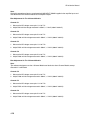
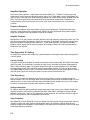
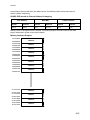
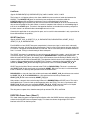
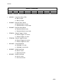
Buttons and Associated Modes
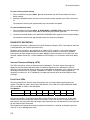
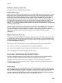
START UP MODES
Right
Mode
Zone 2
DVD2
Zone 3
DVD 2
Mode
Description
-
-
-
Normal
Boot Process executes uninterrupted
*
*
-
AMON
Allows the loading of new code without re-flashing storage RAM
-
*
*
Diagnostics
Places unit into diag mode, allowing individual testing of functionality
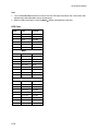
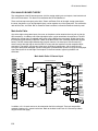
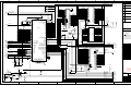
Behind the display window are three LEDs that are driven directly from the processor. These LEDs are
driven via the PE[10:12] port (108, 110, 111). When these port pins are high, the associated LED lights.
The following table illustrates their functionality.
DISPLAY LED INDICATORS
PORT BIT
SIGNAL NAME
FUNCTION
PE10
FP_IR_ACK
Yellow LED indicating infra-red remote access
PE11
SYSLED
Blue LED indicating unit is on and functional
PE12
OVLED
Red LED indicating clipping on an audio input
Miscellaneous Peripheral Control
Signals: CPU_WRD_CLK_MON, FLBY/
Timer Channel 0 is used as an interval counter that monitors the period of FSCLK from both the Main
Zone and Zone 2. The FPGA Multiplexes each clock signal into the TIOC0A port (85) as signal
CPU_WRD_CLK_MON. With each rising edge of FSCLK, the event timer is restarted and the period is
verified by count value.
FLBY/ is output from the storage FLASHRAM (U26) to indicate that the device is busy either during an
erase or re-programming operation. The processor device monitors this signal via the PE14 port (1).
When the signal is low, the FLASHRAM is not ready for read accesses. When high, the device may be
accessed as normal.
DRAM (U42)
The DRAM used in this product is a standard 70nS 1Mx16 Fast Page Mode device (U42). The processor
executes all software instructions from this device, except for the earliest phases of boot up. After DRAM
testing has passed, all of the system code that resides in the FLASHRAM is migrated to the DRAM for
execution. The data bus from the CPU is one word wide, as mandated by the fact that all instructions are
word length. As all accesses are word wide, the address bus to the DRAM is oriented on word
boundaries, hence the 10-bit address beginning at CPUADDR1 instead of CPUADDR0.
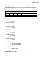
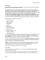
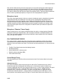
Boot Mode Jumper Selection
The RV-8 supports multiple booting options to aid in software development. In the final product, only one
of these modes is available, booting from FLASH, as described on page 6-15. For development, booting
may be accomplished from either the EEPROM or the ROMulator by proper jumper selection, as
6-13