1
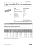
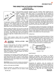
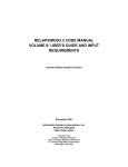
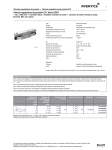
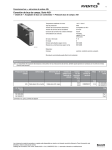
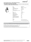
®
MARINE CONTROL SYSTEM
INSTALLATION AND SERVICE MANUAL
FOR
LOGICMASTER CONTROL UNIT
PART NO. R431007538 (P -090141-00000)
WARNING: INSTALLATION AND
MOUNTING
The user of these devices must conform to all applicable
electrical, mechanical, piping and other codes in the
installation, operation or repair of these devices.
INSTALLATION! Do not attempt to install, operate or
repair these devices without proper training in the
technique of working on pneumatic or hydraulic systems
and devices, unless under trained supervision.
Compressed air and hydraulic systems contain high
levels of stored energy. Do not attempt to connect,
disconnect or repair these products when a system is
under pressure. Always exhaust or drain the pressure
from a system before performing any service work.
Failure to do so can result in serious personal injury.
MOUNTING! Devices should be mounted and positioned
in such a manner that they cannot be accidentally
operated.
SM-1200.5108
TABLE OF CONTENTS
TITLE
PAGE
GENERAL DESCRIPTION
2
DESCRIPTION OF OPERATION
2
ADJUSTMENTS & SETTINGS
3
COMPONENT LOCATION & MATERIALS
4
SCHEMATIC DIAGRAM
5
INSTALLATION DATA
6
SERVICE PARTS INFORMATION
SHUTTLE VALVE
FLOW CONTROL VALVE
MULTI-FUNCTION LOGIC VALVE
LOGIC TIMER UNIT
8-11
GENERAL DESCRIPTION
The LOGICMASTER® Control Unit is designed
for service with hydraulic clutch reverse gears.
The LOGICMASTER combines proven, dependable control components into a factory assembled
and tested unit ready for shipboard installation.
Shipboard piping connections are made to the
tapped manifold connections as specified on
installation diagram. Care must be exercised in
the shipboard installation and piping to insure a
satisfactory control installation.
The LOGICMASTER Unit should be located in
close proximity to the reverse gear to minimize
the length of tubing runs to the reverse gear selector cylinder, and engine governor actuator, and
the trolling valve positioned.
All tubing runs should be securely fastened and
insulated, where necessary for maximum protection against vibration damage and metal-to-metal
surface chafing. Tubing runs should be located
such that they will be protected and not in exposed locations susceptible to undesired usage,
such as foot steps or hand holds, which may lead
to breakage or ultimate flattening of the tubing
with consequent flow restrictions. Flexible connections should be provided between all engine
mounted devices and connections. All tubing
bends should be accomplished with smooth radius bends to avoid pinching and flow restriction.
Factory recommended control systems provide for
filtering of the supply air to remove foreign material.
Adequate shipboard procedures must be exercised
to insure that the main ship’s air supply system is
properly drained and maintained to prevent
excessive condensation and moisture carry-over
into the control system supply.
DESCRIPTION OF OPERATION
This control system provides interlocked and
sequenced operation of the reverse gear engagement and engine speed control to insure proper
operation of the propulsion machinery no matter
how the operator manipulates the remotely
mounted control lever. The control system incorporates the following interlocks and operational
features.
1. TIME REVERSING INTERLOCK . . .
Holds the reverse gear control in neutral
position for a preset time on reversals, even
though the remote control lever is shifted
directly through neutral.
This allows the
engine and propeller speed to decrease to an
acceptable level before reversal is initiated.
Timing is adjustable.
2. THROTTLE CONTROL INTERLOCK. . .
IMPORTANT - All tubing lines should be blown
through with clean, dry air prior to making the
final connection at each end to insure that all cuttings, chips, dirt, and foreign material is removed.
If brazed or soldered connections or couplings
are used, extreme care should be exercised to
insure that flux is not introduced into the control
lines. All piping connections should be pressure
tested to insure zero leakage.
For optimum service, a constant 100 psi (6.9 bar)
air supply should be maintained for the control
system. Adequate precautions should be taken in
the shipboard air system to insure a reasonably
clean, dry air supply for the control system and
LOGICMASTER Unit operation.
Page 2
The throttle control interlock and intercept
delay timer allows the clutch control to shift
before engine speed advances from the
remote control station to prevent high engine
speed during clutch engagement and resultant
gear wear.
1. REVERSAL INTERLOCK TIMING
FLOREG® Flow Control Valve(5) and (6), in
conjunction with interlock valves (9) and (10),
provide a reversal time interlock to insure that
the rotation change-over valve is held in neutral for a preset time on reversals, even
though the remote control lever is shifted directly through neutral. This allows the engine
speed to decrease to an acceptable level before reversal is initiated and for application of
shaft brake to stop the propeller. To shorten
the timing, back out on the adjusting screws
for
timer unit (5) and (6) as required. Turn in to
lengthen amount of time Unit (5) controls
timing from Ahead to Astern. Unit (6) controls
timing from Astern to Ahead. This timing is
factory set for 4 seconds.
The control system will operate in the following
manner:
For Ahead operation, a signal is delivered
from the remote control station into
LOGICMASTER® connection 1C to the
normally open reversing interlock valve
(10). This pressure passes through valve
(10) out connection 1A to activate the reverse gear control cylinder into Ahead
position. The Ahead signal also passes
1. Through shuttle valve (1) to throttle
intercept delay timer (7) and to activate
throttle intercept valve (8) to connect the
remote speed line through to valve (11) to
the governor actuator.
In the event of a loss of control air
supply, interlock valve (8) will open to
exhaust the speed signal at the governor
actuator which will reduce the engine
speed to idle thus alerting the operator to
the problem.
2. THROTTLE INTERCEPT TIMER
2. Ahead signal passes through timer unit (5)
to the control connection of interlock valve
(9) installed in the Astern line 3C. Valve
(9) is actuated to intercept the astern line
and prevent any astern actuation until the
ahead signal is fully vented. Thus on
reversals, a neutral time interlock is
provided to permit the engine and
propeller speeds to decrease to an
acceptable level before reversal is
initiated. The neutral time is adjustable by
means of timer unit (5) for ahead to astern
and (6) for astern to ahead.
ADJUSTMENTS & SETTINGS
The following adjustments and settings are made
during the factory test of the LOGICMASTER unit
but may require additional tuning on shipboard to
provide the optimum system operation. All factory
adjustments are accomplished with a control
system operating pressure of 100 psi (6.9 bar).
Page 3
Throttle control is applied to the engine at a
controlled rate by the actuation of interlock
valve (7) when a direction signal is applied
from remote control station to the reverse gear
shifting cylinder. The time required for the
throttle signal to increase from idle to full
speed is controlled by Floreg Valve (7). This
is factory set for a four-second delay. To
shorten this time, the adjusting screw should
be turned in to lengthen time delay. The effect
of the setting can be observed by the
response of the governor actuator during
operation.
COMPONENT LOCATION & MATERIAL LIST
SHUTTLE
VALVE
BLANKING
PAD
BLANKING
PAD
BLANKING
PAD
(1)
(2)
(3)
(4)
REVERSAL
TIMER
AHD. TO
ASTERN
REVERSAL
TIMER
AST. TO
AHEAD
THROTTE
INTERCEPT
TIMER
THROTTLE
INTERCEPT
(5)
(6)
(7)
(8)
AHD. TO
ASTERN
INTERLOCK
AST. TO
AHD.
INTERLOCK
SHUTTLE
PLATE
BLANKING
PAD
(9)
(10)
(11)
(12)
(13)
3A
(13)
3C
1A
1C
8A
8C
Plug
LOGICMASTER® CONTROL PANEL
REF.
NEW PART NO.
OLD PART NO.
DESCRIPTION
1
R431005928
P -061971-00000
Shuttle Valve
2&4
R431006237
P -063396-00002
Blanking Pad
3 & 12
R431006237
P -063396-00002
Blanking Pad
5&6
R431006336
P -064003-00001
Timer Unit - consisting of: Flow Control R431005931 (Old part
no. P -061975-00002) and Volume R431006227 (Old part no.
P -063395-00003)
7
R431006335
P -064003-00000
Timer Unit - consisting of: Flow Control R431005931 (old part
no. P -061975-00002) and Volume R431006228 (old part no.
P -063395-00004) (time in)
8
R431005980
P -062016-00004
Multifunction Logic Valve - 80 psi
9
R431005976
P -062016-00000
Multifunction Logic Valve - 15 psi
10
R431005976
P -062016-00000
Multifunction Logic Valve - 15 psi
11
R431007021
P -067150-00001
Shuttle Plate
13
R431006263
P -063431-00000
Pressure Indicator
14
R431002134
P -049788-00008
Air Gage
Page 4
LOGICMASTER® CONTROL UNIT SCHEMATIC
R431007538 (P -090141-00000)
Page 5
PARTS LIST
LOGICMASTER® UNIT
REF.
QTY.
DESCRIPTION
NEW PART NO.
OLD PART NO.
1
1
Shuttle Valve (See page 10)
R431005928
P -061971-00000
2, 3 & 4
2
Blanking Plate
R431006237
P -063396-00002
5&6
2
Timer unit (See page 8) Consisting of:
R431006336
P -064003-00001
7
1
(A) - Flow Control Valve (See page 9)
--
--
(B) - Timing Volume (Time Out)
--
--
Timer Unit (See page 8) Consisting of:
R431006335
P -064003-00000
(A) - Flow Control Valve (See page 9)
--
--
(B) - Timing Volume (Time In)
--
--
8
1
Logic Valve - 80 psi (See page 11)
R431005980
P -062016-00004
9 & 10
2
Logic Valve - 15 psi (See page 11)
R431005976
P -062016-00000
11
1
Shuttle Plate
R431007021
P -067150-00001
12
1
Blanking Plate
R431006237
P -063396-00002
13
2
Pressure Indicator
R431006263
P -063431-00000
14
1
Air Gage (0-160)
R431002134
P -049788-00008
15
1
Upper Header Bar
R431006045
P -062370-00000
16
1
Circuit Plate Assembly
R431007533
P -090070-00001
17
1
Lower Header Bar
R431006262
P -063430-00000
18
16
“O” Ring Seal
R432012138
P -049708-00012
19
10
All Screw, No. 8 x 1”
R431002312
P -049856-00124
20
9
Pipe Plug
R431002133
P -049787-00000
21
4
Mounting Screw, No. 8 x 1 1/2”
R431001772
P -049467-00013
22
6
Mounting Screw, No. 8 x 3 1/2”
R431001771
P -049467-00012
23
6
Mounting Screw, No. 8 x 5 1/2”
R431001775
P -049467-00016
24
8
Mounting Screw, No. 8 x 2”
R431001768
P -049467-00007
27
54
“O” Ring Seal
R431002010
P -049708-00106
28
4
Spacers
R431006270
P -063458-00000
29
4
Mounting Screw
R431002247
P -049835-00014
30
4
Lockwasher
R431002572
P -049982-00006
31
1
Enclosure
R431006271
P -063459-00000
Page 6
LOGICMASTER® CONTROL UNIT
Typical For All Valves
Page 7
LOGIC TIMER UNIT
Logic Timer Unit, Complete
REF. QTY.
Time In
Time Out
New Part No.
Old Part No.
R431006335
R431006336
P -064003-00000
P -064003-00001
DESCRIPTION
NEW PART NO.
OLD PART NO.
1
1
Logic Flow Control Valve (See parts list B6-105.03)
R431005931
P -061975-00002
2
1
Volume - Time In - For R431006335 (P -064003-00000)
R431006228
P -063395-00004
1
Volume - Time Out - For R431006336 (P -064003-00001)
R431006227
P -063395-00003
*3
2
“O” Ring, 3/8” O.D.
See Kit
See Kit
*4
1
“O” Ring, 1” O.D.
See Kit
See Kit
5
2
Mounting Screw, No. 8-32 x 5-1/2” LG
R431001775
P -049467-00016
* Kit part number: R432006224 (Old part number: P -063393-00000)
Page 8
LOGIC FLOW CONTROL VALVE
LOGIC FLOW CONTROL VALVE, Complete R431005931 (P -061975-00002)
REF.
QTY.
DESCRIPTION
NEW PART NO.
OLD PART NO.
1
2
SCREW, 8-32 x 1 3/4
R431001692
P -049109-00002
2
2
LOCKWASHER
R432012235
P -049866-00003
3*
2
“O” RING, 3/8” O.D.
See Kit
See Kit
4
1
BASE
R431005956
P -062000-00000
5*
2
“O” RING, 9/16” O.D.
See Kit
See Kit
6
2
FILTER
R431005954
P -061999-00000
7
1
CAP
R431005953
P -061998-00000
8*
1
“O” RING, 3/4” O.D.
See Kit
See Kit
9
1
GUIDE
R431005952
P -061997-00000
10*
1
“U” CUP
See Kit
See Kit
11*
1
“O” RING, 5/16” O.D.
See Kit
See Kit
12
1
SCREW, Regulating
R431005951
P -061996-00000
13*
1
“O” RING, 1/4” O.D.
See Kit
See Kit
14
1
NUT, Knurled
R431006292
P -063497-00000
15
1
JAM NUT, 10-48 Hex.
R431002426
P -049901-00036
16
1
HOUSING
R431005950
P -061995-00000
* Recommended spare parts to be retained in stock.
Available in Repair Kit form, R432006224 (P -063393-00000)
Page 9
LOGIC SHUTTLE VALVE
LOGIC SHUTTLE VALVE, Complete R431005928 (P -061971-00000)
REF.
QTY.
DESCRIPTION
NEW PART NO.
OLD PART NO.
1
1
BODY
R431005938
P -061979-00001
2*
1
DIAPHRAGM
See Kit
See Kit
3*
1
GASKET
See Kit
See Kit
4
1
COVER
R431005940
P -061980-00001
5
2
SCREW, 8-32 x 3/4
R431001690
P -049109-0000
6*
3
“O” RING, 3/8 O.D.
See Kit
See Kit
* Recommended spare parts to be retained in stock.
Available in Repair Kit Form, R431006240 (P -063400-00000)
Page 10
MULTIFUNCTION LOGIC VALVE
PART NO. R431005976 (P -062016-00000)
6
2
9
4
12
10
14,14A,14B
13
1
16
3
5
7
8
MULTIFUNCTION LOGIC VALVE (15 psi) Complete
MULTIFUNCTION LOGIC VALVE (30 psi) Complete
MULTIFUNCTION LOGIC VALVE (80 psi) Complete
REF.
QTY.
DESCRIPTION
1
1
BODY
2*
1
3*
11
R431005976 (P -062016-00001)
R431005977 (P -062016-00004)
R431005980 (P -062016-00004)
NEW PART NO.
OLD PART NO.
R431007038
P -067247-00000
O-RING, 7/32” x 11/32”
See Kit
See Kit
1
O-RING, 3/8” x 1/2”
See Kit
See Kit
4
1
SPRING, Supply Valve
R431006176
P -063075-00000
5*
1
VALVE, Supply
See Kit
See Kit
6*
1
GASKET, Body
See Kit
See Kit
7
1
BODY, Valve Seat
R431007041
P -067249-00000
8
1
SPRING, Exhaust Valve
R431003030
P -052889-00000
9
1
SEAT, Exhaust Valve
R431005945
P -061986-00001
10*
1
O-RING, 1/8” x 1/4”
See Kit
See Kit
11*
1
DIAPHRAGM
See Kit
See Kit
12
1
SEAT, Spring
R431005946
P -061987-00000
13
1
COVER
R431007028
P -067156-00000
14
1
SPRING, Regulating (15 psi)
R431005964
P -062012-00000
14A
1
SPRING, Regulating (30 psi)
R431005965
P -062013-00000
14B
1
SPRING, Regulating (80 psi)
R431005489
P -060360-00000
15
2
SCREW, 8-32 x 2-1/4” (Not shown)
R431001693
P -049109-00003
16*
5
O-RING, 3/8” O.D.
See Kit
See Kit
* Recommended spare parts to be retained in stock at all times.
Available in Repair Kit form, order Part No. R431006223 (P -063392-00000)
Page 11
NOTICE TO PRODUCT USERS
1. WARNING: FLUID MEDIA
AVENTICS pneumatic devices are designed and tested for use
with filtered, clean, dry, chemical free air at pressures and
temperatures within the specified limits of the device. For use
with media other than air or for human life support systems,
AVENTICS must be consulted. Hydraulic cylinders are designed
for operation with filtered, clean, petroleum based hydraulic fluid;
operation using fire-resistant or other special types of fluids may
require special packing and seals. Consult the factory.
2. WARNING: MATERIAL COMPATIBILITY
Damage to product seals or other parts caused by the use of
noncompatible lubricants, oil additives or synthetic lubricants in
the air system compressor or line lubrication devices voids
AVENTICS warranty and can result in product failure or other
malfunction. See lubrication recommendations below.
AIR LINE LUBRICANTS! In service higher than 18 cycles per
minute or with continuous flow of air through the device, an air
line lubricator is recommended.* (Do not use line lubrication with
vacuum products.) However, the lubricator must be maintained
since the oil will wash out the grease, and lack of lubrication will
greatly shorten the life expectancy. The oils used in the
lubricator must be compatible with the elastomers in the device.
The elastomers are normally BUNA-N, NEOPRENE, VITON,
SILICONE and HYTREL. AVENTICS recommends the use of
only petroleum based oils without synthetic additives, and with
an aniline point between 180° F and 210° F.
COMPRESSOR LUBRICANTS! All compressors (with the
exception of special "oil free" units) pass oil mist or vapor from
the internal crankcase lubricating system through to the
compressed air. Since even small amounts of non-compatible
lubricants can cause severe seal deterioration (which could
result in component and system failure) special care should be
taken in selecting compatible compressor lubricants.
3. WARNING: INSTALLATION AND MOUNTING
The user of these devices must conform to all applicable
electrical, mechanical, piping and other codes in the installation,
operation or repair of these devices.
disconnect or repair these products when a system is under
pressure. Always exhaust or drain the pressure from a system
before performing any service work. Failure to do so can result
in serious personal injury.
MOUNTING! Devices should be mounted and positioned in such
a manner that they cannot be accidentally operated.
4. WARNING: APPLICATION AND USE OF PRODUCTS
The possibility does exist for any device or accessory to fail to
operate properly through misuse, wear or malfunction. The user
must consider these possibilities and should provide appropriate
safe guards in the application or system design to prevent
personal injury or property damage in the event of a malfunction.
5. WARNING: CONVERSION, MAINTENANCE AND REPAIR
When a device is disassembled for conversion to a different
configuration, maintenance or repair, the device must be tested
for leakage and proper operation after being reassembled and
prior to installation.
MAINTENANCE AND REPAIR! Maintenance periods should be
scheduled in accordance with frequency of use and working
conditions. All AVENTICS products should provide a minimum of
1,000,000 cycles of maintenance free service when used and
lubricated as recommended. However, these products should be
visually inspected for defects and given an "in system" operating
performance and leakage test once a year. Where devices
require a major repair as a result of the one million cycles, one
year, or routine inspection, the device must be disassembled,
cleaned, inspected, parts replaced as required, rebuilt and
tested for leakage and proper operation prior to installation. See
individual catalogs for specific cycle life estimates.
6. PRODUCT CHANGES
Product changes including specifications, features, designs and
availability are subject to change at any time without notice. For
critical dimensions or specifications, contact factory.
*Many AVENTICS pneumatic valves and cylinders can operate
with or without air line lubrication; see individual sales catalogs
for details.
INSTALLATION ! Do not attempt to install, operate or repair
these devices without proper training in the technique of working
on pneumatic or hydraulic systems and devices, unless under
trained supervision. Compressed air and hydraulic systems
contain high levels of stored energy. Do not attempt to connect,
LIMITATIONS OF WARRANTIES & REMEDIES
AVENTICS warrants its products sold by it to be free from defects in material and workmanship to the following:
For twelve months after shipment AVENTICS will repair or replace (F.O.B. our works), at its option, any equipment which under
normal conditions of use and service proves to be defective in material or workmanship at no charge to the purchaser. No charge will
be made for labor with respect to defects covered by this Warranty, provided that the work is done by AVENTICS or any of its
authorized service facilities. However, this Warranty does not cover expenses incurred in the removal and reinstallation of any
product, nor any downtime incurred, whether or not proved defective.
All repairs and replacement parts provided under this Warranty policy will assume the identity, for warranty purposes, of the part
replaced, and the warranty on such replacement parts will expire when the warranty on the original part would have expired. Claims
must be submitted within thirty days of the failure or be subject to rejection.
This Warranty is not transferable beyond the first using purchaser. Specifically, excluded from this Warranty are failures caused by
misuse, neglect, abuse, improper operation or filtration, extreme temperatures, or unauthorized service or parts. This Warranty also
excludes the use of lubricants, fluids or air line additives that are not compatible with seals or diaphragms used in the products. This
Warranty sets out the purchaser's exclusive remedies with respect to products covered by it, whether for negligence or otherwise.
Neither, AVENTICS nor any of its affiliates will be liable for consequential or incidental damages or other losses or expenses incurred
by reason of the use or sale of such products. Our liability (except as to title) arising out of the sale, use or operation of any product or
parts, whether on warranty, contract or negligence (including claims for consequential or incidental damage) shall not in any event
exceed the cost of replacing the defective products and, upon expiration of the warranted period as herein provided, all such liability is
terminated. THIS WARRANTY IS IN LIEU OF ALL OTHER WARRANTIES, EXPRESS OR IMPLIED, WHETHER FOR
MERCHANTABILITY OR FITNESS FOR A PARTICULAR PURPOSE OR OTHERWISE. No attempt to alter, amend or extend this
Warranty shall be effective unless authorized in writing by an officer of AVENTICS Corporation.
AVENTICS reserves the right to discontinue manufacture of any product, or change product materials, design or specifications without
notice.
Page 12