1
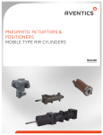
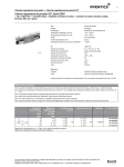
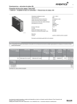
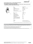
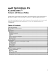
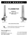
TWO DIRECTION ACTUATOR POSITIONERS
Linear Piston Type
SERVICE MANUAL
The two-direction pneumatic
positioner is a low-sensitivity,
infinite positioning device
that is controlled by a
graduating control valve,
such as AVENTICS Type “H”
Controlair® Valve. Type “M”
Pressure Control Valve or
Flexair®
Valve.
The
positioner has a wide range
of applications including positioning of 4-way hydraulic
valves, over center hydraulic pumps and other low-force
mechanisms. It is corrosion-resistant and constructed of
lightweight, die-cast, anodized aluminum with a chromeplated piston rod and long-wearing synthetic rubber seals.
through the air lines. Therefore, before installing the twodirection positioner, all air lines in the system should be
blown clean. It is recommended that the positioner be
mounted with the ports facing down. Gravity can then assist
in preventing foreign material from accumulating in the
positioner by removing it through the control valve exhaust.
In providing a mounting for the positioner, an adjustable link
must be included between the piston rod and the lever to
which the rod is connected. The positioner stroke should be
checked in its center position when aligned with the lever to
be operated. Check for exact register, making sure the
clevis pin is free from load in the center position.
This procedure will allow any inaccuracies in leverage ratio
or manufacturing tolerance to be absorbed at the extremes
of the stroke where exact registration is of least importance.
Also, any inaccuracies will be divided between the extreme
positions. When alignment is done at one of the extreme
positions, inaccuracies are all in the same direction.
Maximum stroke of the piston rod is one inch on each side
of the center position, making a total piston rod travel of two
inches. External envelope dimensions of the positioner do
not change. The complete part number of the positioner
and the part number of the piston stop (13A) will have an
identical four-digit suffix. Available strokes are shown in the OPERATION
parts list.
Maximum pressure of the two-direction positioner is 150 psi
NOTE: Control pressure should match the operating (10.3 bar) at a temperature range of –40 F to 165 F (-40C to
pressure of the positioner to eliminate any lost motion in the 60°C). The positioner is held in its center position by a coil
control valve.
spring caged on the piston rod. When air pressure is
supplied to the Cap-End Port, the piston rod moves to its
WARNING: INSTALLATION AND extended position. When pressure is supplied to the HeadEnd Port, the piston rod moves to its retracted position.
MOUNTING
The user of these devices must conform to all applicable
electrical, mechanical, piping and other codes in the
installation, operation or repair of these devices.
INSTALLATION! Do not attempt to install, operate or repair
these devices without proper training in the technique of
working on pneumatic or hydraulic systems and devices,
unless under trained supervision.
Compressed air and hydraulic systems contain high levels
of stored energy. Do not attempt to connect, disconnect or
repair these products when a system is under pressure.
Always exhaust or drain the pressure from a system before
performing any service work. Failure to do so can result in
serious personal injury.
MAINTENANCE
Periodically disassemble the positioner for cleaning,
inspection and lubrication. Clean all metal parts with a
nonflammable solvent, and wash all rubber parts with soap
and water. Rinse thoroughly and blow dry with a lowpressure air jet. Replace those parts which are damaged or
worn.
MOUNTING! Devices should be mounted and positioned in
Reassemble the positioner, using the exploded and
such a manner that they cannot be accidentally operated.
assembly views as reference. No special tools required. To
avoid cutting or nicking the piston “O” ring, carefully insert
INSTALLATION AND ADJUSTMENT
the piston rod assembly into the positioner bore with the
Because positioners are installed at the end of an air piston tilted at a slight angle. As the assembly proceeds,
system, they are vulnerable to dirt and moisture carried lubricate all “O” rings with Dow Corning Number 55
Pneumatic Grease.
SM-900.4404
EXPLODED VIEW
Page 2
PARTS LIST
REF
QTY
————-
————-
REF
QTY
1
2
3
4
5*
6*
7*
8
9
10*
11*
12
13A
13B
13C
14
15A
15B
15C
16
16A
17
18
1
4
4
1
1
1
1
1
1
1
1
1
1
1
1
As Req.
1
1
1
1
1
1
1
DESCRIPTION
LINEAR POSITIONER TYPE C SPRING CENT ACT
LINEAR POSITIONER TYPE C SPRING CENT ACT
LINEAR POSITIONER TYPE C SPRING CENT ACT
LINEAR POSITIONER 1.75X1 TYPE C SPR CENT
DESCRIPTION
Nut, 7/16” - 20 Jam
Screw, 1/4”-20 x 7/8” Hex.- Head Cap
Washer, 1/4” Lock
Head, Bushed
Rod wiper
Quad Ring 11/16” OD
Tetraseal, 2-3/8” OD
1/4”-28 Lock Nut
Piston
"O" Ring, 1-3/4” OD
"O" Ring , 3/8” OD
Washer, Piston
Piston Stop for R431004748
Piston Stop for R431004749
Piston Stop for R431005261 & R431006349
Plain Washer 1 X OD 1 7/16 X .032
Compression Spring 0-60
Compression Spring 20-72
Compression Spring
Spring Cage (except R431006349)
Spring Cage for R431006349
Piston Rod
Body
PART
NUMBER
R431004748
R431004749
R431005261
R431006349
PREVIOUS PART
NUMBER
P -058822-00500
P -058822-00750
P -059833-01000
P -064076-01000
PART
NUMBER
R431002447
R431002219
R431002345
R431004068
See Kit
See Kit
See Kit
R431001871
R431004033
See Kit
See Kit
R431002166
R431004074
R431004078
R431004081
R431002172
R431004802
R431005265
R431006358
R431004878
UNKNOWN
R431004069
R431004061
PREVIOUS PART
NUMBER
P -049903-00020
P -049832-00019
P -049866-00009
P -057381-00003
See Kit
See Kit
See Kit
P -049589-00000
P -057374-00000
See Kit
See Kit
P -049804-00045
P -057384-00500
P -057384-00750
P -057384-01000
P -049804-00055
P -058893-00000
P -059850-00000
P -064084-00000
P -059000-00000
P -064085-00085
P -057383-00000
P -057379-00000
* Recommend spare parts to be retained .in stock at all times These parts are available in kit form by
ordering Repair Kit R431006440, previous part number P -064454-00000.
Page 3
Available Forces:
The accompanying graph shows pressure in psi required to overcome the force of the spring as the piston rod is retracted or extended from its center position. From the graph, pounds of spring force can be
determined by multiplying the pressure (psi) by the piston area. The following force ratings are based on
3 psi x 2.4 square inches (piston area).
PART
NUMBER
PREVIOUS
PART NUMBER
R431004748
P -058822-00500 410 in-lb degrees (46 m-N) or 7 lbs (31.1 N) through 1" (25.4 mm)
total travel
R431004749
P -058822-00750 615 in-lb degrees or (69 m-N) 7 lbs (31.1 N) through 1 1/2 " (38.1
mm) total travel
R431005261
P -059833-01000 820 in-lb degrees or (93 m-N) 7 lbs (31.1 N) through 2" (50.8 mm)
total travel
R431006349
P -064076-01000 820 in-lb degrees or (93 m-N) 7 lbs (31.1 N) through 2" (50.8 mm)
total travel
DESCRIPTION
To determine the control valve output pressure at any piston travel for either retracted or extended
strokes, project across the graph from the appropriate stroke length point on the vertical line until the
pressure line is intersected. Project down fro this point to arrive at the pressure in psi. This is the no-load
pressure required of the valve. Normally 3 psi (0.21 bar) above this is required to move a load of 7 lbs.
(31.1N).
Stroke
Metric Inches
25.4
1.00
19
.75
12.7
.50
6.4
.25
0
R431005261 R431006349
R431004748
R431004749
0
20
40
60
80
100
120
(1.4 bar)
(2.8 bar)
(4.1 bar)
(5.5 bar)
(6.9 bar)
(8.3 bar)
PRESSURE - PSI
PISTON
AREA:
Extended 2.4 SQ IN. (1548 sq. mm)
Retracted 2.2 SQ. IN.(1419 sq. mm)
Page 4
NOTICE TO PRODUCT USERS
1. WARNING: FLUID MEDIA
AVENTICS pneumatic devices are designed and tested for use
with filtered, clean, dry, chemical free air at pressures and
temperatures within the specified limits of the device. For use
with media other than air or for human life support systems,
AVENTICS must be consulted. Hydraulic cylinders are designed
for operation with filtered, clean, petroleum based hydraulic fluid;
operation using fire-resistant or other special types of fluids may
require special packing and seals. Consult the factory.
2. WARNING: MATERIAL COMPATIBILITY
Damage to product seals or other parts caused by the use of
noncompatible lubricants, oil additives or synthetic lubricants in
the air system compressor or line lubrication devices voids
AVENTICS warranty and can result in product failure or other
malfunction. See lubrication recommendations below.
AIR LINE LUBRICANTS! In service higher than 18 cycles per
minute or with continuous flow of air through the device, an air
line lubricator is recommended.* (Do not use line lubrication with
vacuum products.) However, the lubricator must be maintained
since the oil will wash out the grease, and lack of lubrication will
greatly shorten the life expectancy. The oils used in the
lubricator must be compatible with the elastomers in the device.
The elastomers are normally BUNA-N, NEOPRENE, VITON,
SILICONE and HYTREL. AVENTICS recommends the use of
only petroleum based oils without synthetic additives, and with
an aniline point between 180° F and 210° F.
COMPRESSOR LUBRICANTS! All compressors (with the
exception of special "oil free" units) pass oil mist or vapor from
the internal crankcase lubricating system through to the
compressed air. Since even small amounts of non-compatible
lubricants can cause severe seal deterioration (which could
result in component and system failure) special care should be
taken in selecting compatible compressor lubricants.
3. WARNING: INSTALLATION AND MOUNTING
The user of these devices must conform to all applicable
electrical, mechanical, piping and other codes in the installation,
operation or repair of these devices.
disconnect or repair these products when a system is under
pressure. Always exhaust or drain the pressure from a system
before performing any service work. Failure to do so can result
in serious personal injury.
MOUNTING! Devices should be mounted and positioned in such
a manner that they cannot be accidentally operated.
4. WARNING: APPLICATION AND USE OF PRODUCTS
The possibility does exist for any device or accessory to fail to
operate properly through misuse, wear or malfunction. The user
must consider these possibilities and should provide appropriate
safe guards in the application or system design to prevent
personal injury or property damage in the event of a malfunction.
5. WARNING: CONVERSION, MAINTENANCE AND REPAIR
When a device is disassembled for conversion to a different
configuration, maintenance or repair, the device must be tested
for leakage and proper operation after being reassembled and
prior to installation.
MAINTENANCE AND REPAIR! Maintenance periods should be
scheduled in accordance with frequency of use and working
conditions. All AVENTICS products should provide a minimum of
1,000,000 cycles of maintenance free service when used and
lubricated as recommended. However, these products should be
visually inspected for defects and given an "in system" operating
performance and leakage test once a year. Where devices
require a major repair as a result of the one million cycles, one
year, or routine inspection, the device must be disassembled,
cleaned, inspected, parts replaced as required, rebuilt and
tested for leakage and proper operation prior to installation. See
individual catalogs for specific cycle life estimates.
6. PRODUCT CHANGES
Product changes including specifications, features, designs and
availability are subject to change at any time without notice. For
critical dimensions or specifications, contact factory.
*Many AVENTICS pneumatic valves and cylinders can operate
with or without air line lubrication; see individual sales catalogs
for details.
INSTALLATION ! Do not attempt to install, operate or repair
these devices without proper training in the technique of working
on pneumatic or hydraulic systems and devices, unless under
trained supervision. Compressed air and hydraulic systems
contain high levels of stored energy. Do not attempt to connect,
LIMITATIONS OF WARRANTIES & REMEDIES
AVENTICS warrants its products sold by it to be free from defects in material and workmanship to the following:
For twelve months after shipment AVENTICS will repair or replace (F.O.B. our works), at its option, any equipment which under
normal conditions of use and service proves to be defective in material or workmanship at no charge to the purchaser. No charge will
be made for labor with respect to defects covered by this Warranty, provided that the work is done by AVENTICS or any of its
authorized service facilities. However, this Warranty does not cover expenses incurred in the removal and reinstallation of any
product, nor any downtime incurred, whether or not proved defective.
All repairs and replacement parts provided under this Warranty policy will assume the identity, for warranty purposes, of the part
replaced, and the warranty on such replacement parts will expire when the warranty on the original part would have expired. Claims
must be submitted within thirty days of the failure or be subject to rejection.
This Warranty is not transferable beyond the first using purchaser. Specifically, excluded from this Warranty are failures caused by
misuse, neglect, abuse, improper operation or filtration, extreme temperatures, or unauthorized service or parts. This Warranty also
excludes the use of lubricants, fluids or air line additives that are not compatible with seals or diaphragms used in the products. This
Warranty sets out the purchaser's exclusive remedies with respect to products covered by it, whether for negligence or otherwise.
Neither, AVENTICS nor any of its affiliates will be liable for consequential or incidental damages or other losses or expenses incurred
by reason of the use or sale of such products. Our liability (except as to title) arising out of the sale, use or operation of any product or
parts, whether on warranty, contract or negligence (including claims for consequential or incidental damage) shall not in any event
exceed the cost of replacing the defective products and, upon expiration of the warranted period as herein provided, all such liability is
terminated. THIS WARRANTY IS IN LIEU OF ALL OTHER WARRANTIES, EXPRESS OR IMPLIED, WHETHER FOR
MERCHANTABILITY OR FITNESS FOR A PARTICULAR PURPOSE OR OTHERWISE. No attempt to alter, amend or extend this
Warranty shall be effective unless authorized in writing by an officer of AVENTICS Corporation.
AVENTICS reserves the right to discontinue manufacture of any product, or change product materials, design or specifications without
notice.
Page 5