1
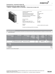
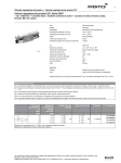
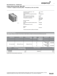
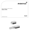
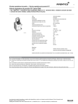
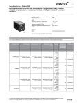
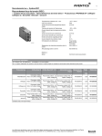
SERIES 740 VALVES
PNEUMATIC DIRECTIONAL CONTROL
Series 740 Valves
Specifications and features
4 Way / 2 & 3 Position
Solenoid & Air Pilot Operated
Diaphragm-Poppet Valve
TECHNICAL DATA:
Port Sizes:
Integrated Fittings for 3/8”, 5/16”, and 8mm tubing
Push-in fitting styles bodies available for metric tubing only
(2 position only)
Working Pressure:
20 PSI minimum
150 PSI maximum
External Pilots not available
Flow: Cv=0.7 - with Integrated Fittings
(Cv=1.3 - comparable flow to threaded part valve)
ELECTRICAL DATA:
Standard Voltage
(all coils are rated for
continuous duty)
Power Consumption
Inrush
24 VAC-50/60 Hz,
110V-50 Hz/120V-60 Hz
220V-50 Hz/240V
6.4 VA
6, 12, 24 VDC
Holding
3.7 VA
2.7 W
Voltage Tolerance: +10% (Except for Explosion proof and
Intrinsically safe solenoids.)
NOTE: Electrical connectors must be ordered separately. One per
solenoid required. See complete listing on Solenoid Connectors page.
Recommended Tubing:
Standard 3/8” O.D> x 0.062” wall - poly tubing
*5/16” O.D. x 0.040 wall - nylon tubing
*8mm x 1.00mm wall poly tubing
*Requires optional tube nut kit (R432015289)
Valves designed for 10mm O.D. x 1mm wall poly tubing are
also available.
Adapters available: 1/4” O.D. x 0.040 wall - poly tubing.
Tube nuts are supplied with each valve for 3/8” x 0.062 wall poly tubing
Features:
x NEMA 4 Electrical protection
x UL recognized & CSA approved coils version available
x Packaged as a cylinder/valve combination with TaskMaster®
cylinders sizes 1 1/2” thru 4”. See catalog SC-200.
x Integrated fittings
x Adjustable built-in flow controls in R and S exhausts on two
position valves
x Cycle life: 20 to 150 million cycles
x Response time for 24VDC single solenoid valve:
(at supply pressure 85 psi)
On (0-77 psi) 18ms or less
Off (85-8 psi) 32 ms or less
52
Series 740 Valves
Single and double solenoid, 5/2
NOTE: Electrical connector must be ordered separately. One
per solenoid required, see Solenoid Connectors page.
All valves on this page come with 3/8” tube nuts designed to
accommodate 3/8” x 0.062” wall poly tubing.
Valves with tube nuts for 5/16” (8mm) tubing, 10mm tubing,
and push-in fitting style bodies available.
NEW PART NO.
OLD PART NO.
VOLTAGE
NEW PART NO.
OLD PART NO.
VOLTAGE
5727495270
PW-067697-00001
110 VAC 50Hz/120 VAC 60Hz
R432016659
PW-067715-00001 110 VAC 50Hz/120 VAC 60Hz
R432016655
PW-067697-00002
220 VAC 50Hz/240 VAC 60Hz
R432016660
PW-067715-00002 220 VAC 50Hz/240 VAC 60Hz
R432016656
PW-067697-00003
6 VDC
R432016661
PW-067715-00003 6 VDC
R432016657
PW-067697-00004
12 VDC
R432016662
PW-067715-00004 12 VDC
5727490220
PW-067697-00005
24 VDC
R432016663
PW-067715-00005 24 VDC
R432016658
PW-067697-00006
24 VAC 50/60 Hz
R432016664
PW-067715-00006 24 VAC 50/60 Hz
without coil
R432002437
R432002436
Unique Manual Override Feature: Single solenoid valves are equipped with a convertible
manual override button.
Valve comes standard with extended locking override. By
snipping tab off of plastic button, override becomes non-locking extended. By snipping
button at first scored line, it becomes a flush non-locking override. By snipping at second
scored line, a flush locking override is obtained, requiring a screwdriver to actuate.
See next page for U.L. recognized and CSA approved coils.
53
without coil
Series 740 Valves
Double solenoid 5/3 and U.L. recognized/CSA approved models
4 Way / 3 Position, Double Solenoid Operated
Diaphragm-Poppet Valve
NOTE: Electrical connector must be ordered separately. One
per solenoid required, see Solenoid Connectors page.
All valves on this page come with 3/8” tube nuts designed to
accommodate 3/8” x 0.062” wall poly tubing.
NEW PART NO.
OLD PART NO.
DESCRIPTION
SYMBOL
CLOSED CENTER VERSION
R432016670
PW-067717-00001
110 VAC 50 Hz/120 VAC 60 Hz
R432016671
PW-067717-00002
220 VAC 50 Hz/240 VAC 60 Hz
R432016672
PW-067717-00003
6 VDC
R432016673
PW-067717-00004
12 VDC
R432016674
PW-067717-00005
24 VDC
R432016675
PW-067717-00006
24 VAC 50/60 Hz
R432002438
without coil
EXHAUST OPEN CENTER VERSION
R432016665
PW-067716-00001
110 VAC 50 Hz/120VAC 60 Hz
R432016666
PW-067716-00002
220 VAC 50 Hz/240 VAC 60 Hz
R432016667
PW-067716-00004
12 VDC
R432016668
PW-067716-00005
24 VDC
R432006669
PW-067716-00006
24 VAC 50/60 Hz
R432002439
without coil
Warning: Do not energize both solenoids at same time or all ports may be pressurized or exhausted.
__________________________________________________________________________________________________________________
4 Way / 2 Position, Solenoid Operated Valves
With U.L. Recognized & CSA Approved Coils
PART NO.
DESCRIPTION
R432034081
5/2 Single Solenoid, w/ 12VDC
R432034082
5/2 Single Solenoid, w/ 24VDC
R432034083
5/2 Single Solenoid, w/ 110VAC 50/60Hz
R432034084
5/2 Double Solenoid, w/ 12VDC
R432034085
5/2 Double Solenoid, w/ 24VDC
R432034086
5/2 Double Solenoid, w/ 110VAC 50/60Hz
R432034087
5/3 Closed Center, w/ 12VDC
R432034088
5/3 Closed Center, w/ 24VDC
R432034089
5/3 Closed Center, w/ 110VAC 50/60Hz
R432034090
5/3 Open Center, w/ 12VDC
R432034091
5/3 Open Center, w/ 24VDC
R432034092
5/3 Open Center, w/ 110VAC 50/60Hz
54
These valves do not include
solenoid connectors. Order
one per solenoid.
Dimensions are the same as
our standard models.
Series 740 Valves
Intrinsically safe solenoid valves, 5/2
Single Solenoid Model
Part No. R432008894
(old no. P - 028044-00005)
55
Series 740 Valves
Solenoid valves 5/2 with larger integrated fittings
Standard Series 740 valve with tube nuts for 5/16” (0.040 wall)
nylon tubing or 8mm (1mm wall) poly tubing.
Push-in fittings are for 10mm (1mm wall) poly tubing.
NOTE: Electrical connectors must be ordered separately. One
per solenoid required, see Solenoid Connectors page.
2 Position, Standard fittings
Single
Solenoid
Double
Solenoid
NEW PART NO.
OLD PART NO.
DESCRIPTION
R432016647
PW-027860-00001
110 VAC 50 Hz/120VAC 60 Hz Single Solenoid
R432016648
PW-027860-00002
220 VAC 50 Hz/240VAC 60 Hz Single Solenoid
R432016649
PW-027860-00005
24 VDC Single Solenoid
R432016650
PW-027860-00006
24 VAC 50/60 Hz Single Solenoid
NEW PART NO.
OLD PART NO.
R432016651
PW-027897-00001
110 VAC 50 Hz/120VAC 60 Hz Double Solenoid
R432016652
PW-027897-00002
220 VAC 50 Hz/240VAC 60 Hz Double Solenoid
R432030385
PW-027897-00004
12 VDC Double Solenoid
R432016653
PW-027897-00005
24 VDC Double Solenoid
R432016654
PW-028797-00006
24 VAC 505/60 Hz Double Solenoid
DESCRIPTION
2 Position, Push-in fittings (10mm O.D. tubing)
Single
Solenoid
Double
Solenoid
NEW PART NO.
OLD PART NO.
DESCRIPTION
5727475280
572-747-528-0
220 VAC 50 Hz/240vac 60 Hz Single Solenoid
5727470220
572-747-022-0
24 VDC Single Solenoid
5727475302
572-747-530-2
Base Valve - No Solenoid*
NEW PART NO.
OLD PART NO.
5727485280
572-748-528-0
220 VAC 50 Hz/240vac 60 Hz Double Solenoid
5727480220
572-748-022-0
24 VDC Double Solenoid
5727485302
572-748-530-2
Base Valve - No Solenoid*
DESCRIPTION
——————————————————————————————————————————————
* Base valves are supplied without coil(s) or connector(s) which must be ordered separately (see later page).
Series 740 Valve with 10mm Supply and Delivery Ports
for higher flow applications—2 Position
Note: Use with 10mm O.D. x 1mm wall poly tubing
NEW PART NO.
OLD PART NO.
DESCRIPTION
R432015405
P -068700-K0000
Single Solenoid
R432015410
P -068704-K0000
Double Solenoid
10mm Valves are supplied without coil(s) or connector(s) which must be ordered separately (see later page).
56
Series 740 Valves
Extra corrosion resistant models
4 Way / 2 and 3 Position Solenoid Operated
Corrosion Resistant Series 740 Valves
All fasteners and exposed metallic parts for the 2-position valves are 300 series stainless steel. The
adjustable built-in flow control adjustment screws for the 3-position valves are zinc plated carbon
steel, with all other fasteners and exposed metallic parts 300 series stainless steel. These valves
are recommended for most daily wash-down applications such as food processing, breweries
and dairy plants, or anywhere else that corrosion can be a problem. Dimensions are the same as
standard valves.
CORROSION RESISTANT MODELS
2-POSITION VALVES Without Indicator Lights
New Part
Number
R432015590
R432015591
R432015592
R432015593
R432015594
R432015597
R432015598
R432015599
Old Part
Number
P -069294-00001
P -069294-00002
P -069294-00004
P -069294-00005
P -069294-00006
P -069297-00001
P -069297-00002
P -069297-00005
Description
110VAC-50Hz/120VAC-60Hz Single Sol.
220VAC-50Hz/240VAC-60Hz Single Sol.
12 VDC Single Solenoid
24 VDC Single Solenoid
24 VAC-50/60Hz Single Solenoid
110VAC-50Hz/120VAC-60Hz Double Sol.
220VAC-50Hz/240VAC-60Hz Double Sol.
24 VDC Double Solenoid
2-POSITION VALVES With Indicator Lights
New Part
Number
R432015613
R432015614
R432015615
R432015616
R432015617
R432015618
R432015619
Old Part
Number
P -069344-00001
P -069344-00004
P -069344-00005
P -069344-00006
P -069345-00001
P -069345-00002
P -069345-00005
Description
110VAC-50Hz/120VAC-60Hz Single Sol.
12 VDC Single Solenoid
24 VDC Single Solenoid
24 VAC-50/60Hz Single Solenoid
110VAC-50Hz/120VAC-60Hz Double Sol.
220V-50Hz/240V-60Hz Double Solenoid
24 VDC Double Solenoid
3-POSITION VALVES Without Indicator Lights
New Part
Number
R432008644
R432008645
R432008862
R432008863
Old Part
Number
P -026564-00001
P -026564-00005
P -027873-00001
P -027873-00005
Description
110VAC-50Hz/120VAC-60Hz Closed Ctr.
12 VDC Closed Center
110VAC-50Hz/120VAC-60Hz Open Center
12 VDC Exhaust Open Center
57
Series 740 Valves
Air pilot, single and double
Part No. R432013808
(old P - 067698-00000)
Part No. R432013810
(old P - 067700-00000)
Double Air Bleeder Valve:
Part No. R432008442 (old P –026125-00000)
58
Series 740 Valves
Manifolds and gang stacking
Manifold Mounting, Snap-Together Assembly
(Factory assembled manifolds also available)
Gang Stacking Arrangement
NEW PART NO.
OLD PART NO.
DESCRIPTION
R432013811
*P -067701-00000
Inlet Segment
R432013812
*P -067702-00000
End Segment
R432013813
*P -067703-00000
Station Segment
R432015880
*P -069881-00000
Single Subbase (Identical to inlet
segment except rear cavities are
blocked. Used to manifold
mount one valve only.
O-Ring P/N 890701004 included with
Segments. Lubricate “O” Rings with
Dow Corning 55 before assembly.
Manifold End
Segment
R432013812
Manifold
Station Segment
R432013813
Manifold
Inlet Segment
R432013811
59
R432013852
Part No. R432013853
O-Ring Kit (included
with manifold
segments)
Series 740 Valves
Accessories
ACCESSORIES
R432015301
Elbow Fitting with nuts for
3/8” & 5/16” O.D. tubing
R432015479
Reducer Elbow Fitting with nut
for 1/4” O.D. (.040” wall) tubing
R432015475
Reducer Fitting with nut
For 1/4” O.D. tubing
R432013850
Exhaust Tube Nut & Silencer
(2 kits shown)
8919905502 (3/8”, 5/16” or 8 mm)
8919905512 (10 mm)
Blanking Cap
(converts 4-way to 3-way)
R432013852
Sheer Plug Knockout for
Stacking
R432015513
Exhaust Fitting Adapter Kit
(converts the standard exhaust fitting to a
tube fitting for external piping)
R432015289
Tube Nuts (3 ea.) for 5/16”
(.040” wall) O.D. nylon tubing
or 8mm (1mm wall) O.D. poly
tubing
R432015287
Tube Nuts (3 ea.) for 3/8”
O.D. (.062” wall) poly tubing
R432015511
Manifold Blanking Plate
(use to block one segment)
R432015330
Manifold Bushing Kit
for two supply pressures
R432015512
Individual Manifold Supply Pressure Kit-mounts underneath manifold segment (not included)
R432015527
Double Elbow Fitting for 1/4”
O.D. tubing
R432015526
Double Elbow Fitting for 3/8” &
5/16” O.D. tubing
R432015525
Barb Fitting for 1/4” I.D.
Reinforced Hose
60
Series 740 Valves
Repair Kits
Repair Kits and Parts
Part No.
R432013884
R432013885
Old Part No.
P -067916-00000
P -067917-00000
Description
Single Solenoid Body Repair Kit
Double Solenoid Body Repair Kit
(includes 3 position valves also)
Air Pilot Operator Kit
Single Solenoid Body Assembly
Double Solenoid Body Assembly
Solenoid Repair Kit, includes
armature, plunger/spring & seal
Solenoid Retainer Kit
Valve Latch & Spring
Valve Manifold Station "O" Ring Kit,
(to attach valve to manifold)
R432013854
R432013816
R432013814
R432015687
P -067817-00000
P -067705-K0000
P -067704-K0000
P -069541-00000
8994702802
R432013839
R432013853
H -899470-02802
P -067782-00000
P -067816-00000
Part No.
R432015349
R432013840
R432013841
R432029180
R432013842
R432013843
(Includes Armature, Coil, & Mtg. Hardware)
Old Part No.
Description
P -068648-00000
24 VAC-50/60Hz
P -067783-00000
110VAC-50Hz/120VAC-60Hz
P -067784-00000
220VAC-50Hz/240VAC-60Hz
P -067785-00000
6 VDC
P -067786-00000
12 VDC
P -067787-00000
24 VDC
Solenoid Kits
U.L. Recognized & C.S.A. Approved Coils
Part No.
R432034080
R432009779
R432009778
Description
12 VDC
24 VDC
110 VAC-50/60Hz
Standard Coils
Part No.
R432011985
R432011986
R432011988
R432011989
R432011990
Model Number
P -048835-00001
P -048835-00002
P -048835-00004
P -048835-00005
P -048835-00006
Description
110VAC-50Hz/120VAC-60Hz
220VAC-50Hz/240VAC-60Hz
12 VDC
24 VDC
24 VAC-50/60Hz
Coils for Corrosion Resistant Valves
Part No.
5428457072
5428457082
5420507012
5450507022
5428457022
Model Number
H -542845-07072
H -542845-07082
H -542050-07012
H -542050-07022
H -542845-07022
61
Description
110VAC-50Hz/120VAC-60Hz
220VAC-50Hz/240VAC-60Hz
12 VDC
24 VDC
24 VAC-50/60Hz
NOTICE TO PRODUCT USERS
1. WARNING: FLUID MEDIA
AVENTICS pneumatic devices are designed and tested for use with
filtered, clean, dry, chemical free air at pressures and temperatures
within the specified limits of the device. For use with media other than
air or for human life support systems, AVENTICS must be consulted.
Hydraulic cylinders are designed for operation with filtered, clean,
petroleum based hydraulic fluid; operation using fire-resistant or other
special types of fluids may require special packing and seals. Consult the
factory.
2. WARNING: MATERIAL COMPATIBILITY
Damage to product seals or other parts caused by the use of noncompatible lubricants, oil additives or synthetic lubricants in the air
system compressor or line lubrication devices voids the AVENTICS
warranty and can result in product failure or other malfunction. See
lubrication recommendations below.
AIR LINE LUBRICANTS! In service higher than 18 cycles per minute or
with continuous flow of air through the device, an air line lubricator
is recommended.* (Do not use line lubrication with vacuum products.)
However, the lubricator must be maintained since the oil will wash
out the grease, and lack of lubrication will greatly shorten the life
expectancy. The oils used in the lubricator must be compatible with
the elastomers in the device. The elastomers are normally BUNA-N,
NEOPRENE, VITON, SILICONE and HYTREL. AVENTICS recommends the
use of only petroleum based oils without synthetic additives, and with an
aniline point between 180° F and 210° F.
COMPRESSOR LUBRICANTS! All compressors (with the exception
of special "oil free" units) pass oil mist or vapor from the internal
crankcase lubricating system through to the compressed air. Since
even small amounts of non-compatible lubricants can cause severe
seal deterioration (which could result in component and system failure)
special care should be taken in selecting compatible compressor
lubricants.
3. WARNING: INSTALLATION AND MOUNTING
The user of these devices must conform to all applicable electrical,
mechanical, piping and other codes in the installation, operation or repair
of these devices.
INSTALLATION ! Do not attempt to install, operate or repair these devices
without proper training in the technique of working on pneumatic or
hydraulic systems and devices, unless under trained supervision.
Compressed air and hydraulic systems contain high levels of stored
energy. Do not attempt to connect, disconnect or repair these products
when a system is under pressure. Always exhaust or drain the pressure
from a system before performing any service work. Failure to do so can
result in serious personal injury.
MOUNTING! Devices should be mounted and positioned in such a manner
that they cannot be accidentally operated.
4. WARNING: APPLICATION AND USE OF PRODUCTS
The possibility does exist for any device or accessory to fail to operate
properly through misuse, wear or malfunction. The user must consider
these possibilities and should provide appropriate safe guards in the
application or system design to prevent personal injury or property
damage in the event of a malfunction.
5. WARNING: CONVERSION, MAINTENANCE AND REPAIR
When a device is disassembled for conversion to a different
configuration, maintenance or repair, the device must be tested for
leakage and proper operation after being reassembled and prior to
installation.
MAINTENANCE AND REPAIR! Maintenance periods should be scheduled
in accordance with frequency of use and working conditions. All
AVENTICS products should provide a minimum of 1,000,000 cycles of
maintenance free service when used and lubricated as recommended.
However, these products should be visually inspected for defects and
given an "in system" operating performance and leakage test once a
year. Where devices require a major repair as a result of the one million
cycles, one year, or routine inspection, the device must be disassembled,
cleaned, inspected, parts replaced as required, rebuilt and tested
for leakage and proper operation prior to installation. See individual
catalogs for specific cycle life estimates.
6. PRODUCT CHANGES
Product changes including specifications, features, designs and
availability are subject to change at any time without notice. For critical
dimensions or specifications, contact factory.
*Many AVENTICS pneumatic valves and cylinders can operate with or
without air line lubrication; see individual sales catalogs for details.
-Refer to the appropriate service manual for parts and service
information, most are available for download from www.aventics.com/us
LIMITATIONS OF WARRANTIES & REMEDIES
AVENTICS warrants its products sold by it to be free from defects in material and workmanship to the following:
For twelve months after shipment AVENTICS will repair or replace (F.O.B. our works), at its option, any equipment which under normal
conditions of use and service proves to be defective in material or workmanship at no charge to the purchaser. No charge will be
made for labor with respect to defects covered by this Warranty, provided that the work is done by AVENTICS or any of its authorized
service facilities. However, this Warranty does not cover expenses incurred in the removal and reinstallation of any product, nor any
downtime incurred, whether or not proved defective.
All repairs and replacement parts provided under this Warranty policy will assume the identity, for warranty purposes, of the part
replaced, and the warranty on such replacement parts will expire when the warranty on the original part would have expired. Claims
must be submitted within thirty days of the failure or be subject to rejection.
This Warranty is not transferable beyond the first using purchaser. Specifically, excluded from this Warranty are failures caused by
misuse, neglect, abuse, improper operation or filtration, extreme temperatures, or unauthorized service or parts. This Warranty also
excludes the use of lubricants, fluids or air line additives that are not compatible with seals or diaphragms used in the products. This
Warranty sets out the purchaser's exclusive remedies with respect to products covered by it, whether for negligence or otherwise.
Neither, AVENTICS nor any of its affiliates will be liable for consequential or incidental damages or other losses or expenses incurred
by reason of the use or sale of such products. Our liability (except as to title) arising out of the sale, use or operation of any product
or parts, whether on warranty, contract or negligence (including claims for consequential or incidental damage) shall not in any event
exceed the cost of replacing the defective products and, upon expiration of the warranted period as herein provided, all such liability
is terminated. THIS WARRANTY IS IN LIEU OF ALL OTHER WARRANTIES, EXPRESS OR IMPLIED, WHETHER FOR MERCHANTABILITY OR
FITNESS FOR A PARTICULAR PURPOSE OR OTHERWISE. No attempt to alter, amend or extend this Warranty shall be effective unless
authorized in writing by an officer of AVENTICS Corporation.
AVENTICS reserves the right to discontinue manufacture of any product, or change product materials, design or specifications without
notice.
AVENTICS Corporation
1953 Mercer Road
Lexington, KY 40514
Tel 859.254.8031
Fax 800.489.1488
www.aventics.com/us
[email protected]
AVENTICS Incorporated
5515 North Service Rd
Suite #100
Burlington, Ontario L7L 6A6
Tel 905.332.0399
Fax 905.332.8596
www.aventics.com/ca
[email protected]
Further contacts:
www.aventics.com/en/contact
The data specified only serve to
describe the product. No statements
concerning a certain condition or
suitability for a certain application
can be derived from our information.
The information given does not release the user from the obligation of
own judgment and verification. It
must be remembered that our
products are subject to a natural
process of wear and aging. Pages from SC-300/2015-02 online version. Subject to change. Printed in USA. © AVENTICS Corporation
This document, as well as the data, specifications and other information set forth in it, are the exclusive
property of AVENTICS. It may not be reproduced or given to third parties without its consent.