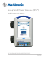
1
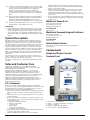
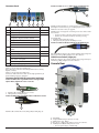
Integrated Power Console (IPC™)
Models EC300 and 1898001
Service Manual Console and Attachments
Rx Only
Notice
This manual is provided primarily for information purposes. Although there are certain
troubleshooting actions that may be attempted by the customers as specifically listed in this
manual, the majority of repairs must be undertaken by Medtronic Xomed or its authorized
representative it otherwise being unsafe to maintain or repair this device.
Released documents are available for viewing/printing @ www.medtronicENT-TechComms.com
™ are trademarks and ® are registered marks of Medtronic, Inc.
Jacobs Chuck® is a registered mark of Jacobs Chuck Manufacturing Company
The information contained in this document was accurate at time of publication. Medtronic reserves the right to make changes in the product described in this manual without notice and without incorporating those changes in any products already sold.
2
Symbols...............................................................................4
General...............................................................................4
Definitions .........................................................................4
Warnings and Precautions.................................................4
Warnings............................................................................ 4
Precaution.......................................................................... 5
System Description.............................................................5
Sales and Customer Care...................................................5
U.S. Customers....................................................................... 5
Medtronic Xomed, Inc. . ...................................................... 5
U.S. Help Line.................................................................... 5
Medtronic Powered Surgical Solutions............................... 5
U.S. Help Line.................................................................... 5
International Service............................................................. 5
Components.......................................................................5
Integrated Power Console................................................ 5
Console Front......................................................................... 5
Connector Panel................................................................ 6
Connector Panel Cable Connection............................... 6
Connector Panel Cable Disconnection (multi pin)...... 6
Cable Disconnection (single pin)................................... 6
Console Rear.......................................................................... 6
Console Pump Designator................................................... 7
Console Specifications.......................................................... 7
Irrigation/Coolant Pumps.................................................... 7
Pump Cartridge Set-up.................................................... 7
Visao® Pump Cartridge.................................................... 8
Visao® Coolant Pump Set-Up.......................................... 8
Standard Pump Set-up..................................................... 8
Accessories/attachments....................................................8
Multifunction Foot Control Unit (FCU)............................ 8
Intelliflow Irrigation Remote Control................................. 8
Endo-Scrub® 2 ....................................................................... 8
Endo-Scrub® 2 Assembly................................................. 9
Suction Irrigator.................................................................... 9
Suction Irrigator Adapter Kit............................................... 9
Handpieces Microdebriders and SC1................................9
Straightshot® M4, Microdebriders, and Midas Rex® SC1.9
Technical Specifications................................................... 10
Straightshot® Magnum® II and Straightshot® III
Microdebriders...................................................................... 10
Technical Specifications................................................... 10
Handpieces Drills...............................................................10
Visao® High-Speed Otologic Drill (Water-Cooled)...... 10
Technical Specifications................................................... 10
Skeeter® Ultra-Lite Oto-Tool System Set-Up and Use. 10
Technical Specifications................................................... 10
Midas Rex® Legend EHS® Motor..................................... 10
Technical Specifications................................................... 11
Midas Rex® Legend EHS Stylus® Motor ........................ 11
Technical Specifications................................................... 11
System Overview................................................................11
Set-Up.................................................................................12
Inspect:............................................................................... 12
Configure System:............................................................. 12
Functional Test.................................................................. 12
Main Screen....................................................................... 12
Power Down...................................................................... 13
Cleaning............................................................................. 13
Calibration.............................................................................. 13
Settings Screen.................................................................. 13
Console Test-Electrical Safety Specifications ............... 13
Troubleshooting.................................................................15
Error Code.............................................................................. 16
Changing the Fuse ................................................................ 17
Symbols
N
Serial Number
Do not dispose of this product in the unsorted municipal waste stream. Dispose of this product according to
local regulations. See http://recycling.Medtronic.Com
for instructions on proper disposal of this product.
Do not use if package is open or damaged
Package Contents
1
2
Pump Head 1
Pump Head 2
Use by Date
Do not Reuse
LOT
Lot Number
Fuse
ACC
REF
REF
Accessory
Catalog Number
AC power
Output
Is approximately equal to
STERILE R Sterilized by radiation. Do not use if package is open or
damaged
STERILE
Non sterile
STERILE EO Sterilized by ethylene oxide. Do not use if package is
EC REP
0123
Table of Contents
open or damaged
Authorized representative in the
european community
This device complies with medical device directive
93/42/EEC
0086
Rx Only
Caution: federal law (U.S.A.) Restricts this device to sale
by or on the order of a physician
! USA
Usa Only
Quantity
Manufacturer
Date of manufacture
Rohs - Environmental friendly use period - China (sj/
t11364-2006.)
3
>120 VAC
ON
<120s
OFF
>180s
Unlocked
Not greater than 120vac
On/Off (main power)
Applied part duty cycle
Use with
<XX° C
XX° C
XX° C
>X° C
Recommended storage temperature and limits.
Conforms to ansi/aami es 60601-1, iec/en 606011. Certified to csa C22.2 No.601.1
Instrument Case
Instrument case
Lubricant/Diffuser
Lubricant/Diffuser
Dissecting Tool
105345
Handpiece
Skeeter® handpiece
Emc compliance mark
EUR · USA · JPN · AUS
Equipotential
Consult instructions for use
Attention see instructions for use
IPX7
M
Protected against vertical water drops
Protected against the effects of temporary immersion in
water
Type bf applied part
Manual Start/Stop
Rf transmitter (interference may occur)
Precaution: Pinch hazard. Keep fingers clear of rollers
BUR
Stim bur connector
NIM
Nim® console connector
EHS
Electrical high speed handpiece connector
Foot pedal connector
Fr
World Wide Standard for medical tubing diameter.
Fine irrigant adjustment
Left foot control unit button
Right foot control unit button
Top foot control unit button
Locked
4
Attachment Attachment
Control Unit Control Unit
Refurbished Refurbished
Accessory Accessory
Protective Earth
IPX1
Dissecting Tool
Regulator Regulator
Bone Mill Bone Mill
Motor
Motor
Brush
Brush
Adapter
TOOL
TUBE
Adapter
Tool control
Tube control
Multi-Use Disposable Attachment
Multi-Use Disposable Attachment
NOTE
IT IS IMPORTANT THAT THE OPERATOR BE FAMILIAR
WITH THIS MANUAL AND THE USER’S GUIDE WITH THEIR
WARNINGS, PRECAUTIONS, PROCEDURES AND SAFETY ISSUES.
General
Uppercase Alphabetic list (A. B. C. etc.) contain introductory
information where Numeric list (1. 2. 3. etc.) are “How To” instructions.
Definitions
Explaining the essential meaning of a word or acronym as used in this
manual.
Also explains changes in words or phrases variations from one product
generation to the next.
FCU – Foot Control Unit
IPC™ - Integrated Power Console
I.V. -
Intravenous
NIM® - Nerve Integrity Monitor - One or all of the following
units: NIM-Response®, NIM-Pulse®, NIM-Response®
2.0, NIM-Pulse® 2.0, NIM-Neuro® 2.0, NIM-Response®
3.0, NIM-Pulse® 3.0, NIM-Neuro® 3.0
Nomenclature The act or process or an instance of naming
Warnings and Precautions
Warnings
W1 The IPC™ shall only be serviced by trained technicians at an
authorized Medtronic service facility
W2 The IPC™ contains live circuitry that can cause injury or death if
the enclosure is opened.
W3 The IPC™ contains live circuitry that can cause injury or death
to operators or patients if assembled incorrectly. This document
and the documents referenced herein are not sufficient to
guarantee correct assembly and operation of the device.
Product specific training and product specific test equipment
is required to ensure the correct operation and assembly of the
IPC™.
W4 This system requires insulated connectors for the StraightShot®
M4 Microdebrider, Straightshot® Magnum® II Microdebrider,
Straightshot® III Microdebrider, Midas Rex® SC1, Visao®, or
Skeeter® handpieces and the Multi Function Foot Control Unit.
W5 Auxiliary Power Outlet with protective cover is for use with the
HydroDebrider™, or Bone Mill consoles only.
Precaution
P1 Prime/Flush Priming is a feature designed to purge air out of the
tubing set(s) during setup. The first time a Prime or Flush button
is pressed it will turn on pump 1 and/or 2 long enough to purge
air out of the tubing set(s). Turning power Off and On resets the
Prime feature. Once pressed all Prime buttons will change to Flush
buttons.
System Description
The IPC™ System is a powered microdebrider, drill and saw system
that will remove soft tissue, hard tissue, bone, and biomaterials during
surgical procedures. The system consists of a power control console,
footswitch, connection cables, and assorted handpieces to drive various
burs, blades, drills, rasps, cannulae, and saws. It includes integrated
irrigation pumps for irrigation of blades, burs and for motor coolant.
The Nerve Integrity Monitor (NIM®) is a separate device that stimulates
and monitors the nerve. This system has connections that allow the
NIM® to be connected with the Visao® handpiece and Stimulating Bur
Guard enabling the NIM® to stimulate and monitor the nerve at the
surgical site.
The system can be used to clear the end of a rigid rod endoscope in
order to maintain good visualization of endoscopic procedures without
having to remove the scope from the surgical site.
This device is intended for use by physicians trained in the procedures
described.
Medtronic will contact your facility promptly with a repair cost
estimate if requested. The customer will be responsible for freight
charges on non-warranted units.
6. When you have loaner equipment and you receive your repaired
unit, please package the loaner equipment as safely as possible
using the foam provided with your repaired equipment. Include
paperwork indicating the unit is a loaner, and Medtronic will credit
your account.
7. Loaner equipment not received by Medtronic within 30 days from
the date that repaired equipment is shipped will be invoiced at full
purchase price.
Medtronic Xomed, Inc.
6743 Southpoint Drive North
Jacksonville, FL 32216 USA
www.medtronicENT.com
U.S. Help Line
(800)-874-5797.
Medtronic Powered Surgical Solutions
4620 North Beach Street
Fort Worth, TX 76137 USA
www.medtronic.com
U.S. Help Line
(800) 468-9710
International Service
International customers should contact their local Medtronic
representative.
Components
Integrated Power Console
Console Front
Sales and Customer Care
Medtronic is committed to provide the highest standard of
workmanship in manufacturing its products. Your system requires
minimal maintenance and calibration.
Servicing and/or modification to the system, or any accessory/
attachment by anyone other than qualified service personnel may
significantly compromise the systems performance and void the
equipment warranty. For best performance, it is recommended that all
service be performed by Medtronic Xomed service personnel.
Medtronic recommends preventative maintenance and screen
calibration scheduled at yearly intervals. Comprehensive testing and
calibration should be performed by returning the entire system to
Medtronic Customer Service.
A
B
U.S. Customers
Should your console or related equipment malfunction, Medtronic
provides, at no charge, loaner equipment shipped to your facility by UPS
or Federal Express for use while your equipment is being serviced by
Medtronic. Please adhere to the following guidelines:
1. When a loaner console is ordered, please reuse the shipping material
and carton when you return your console to Medtronic. Insure the
unit.
2. When a loaner is not ordered, please package the console as safely as
possible and insure.
3. A return goods authorization number is required on repairs. A copy
of your purchase order is required. Make certain the purchase order
includes the following:
• Shipping and billing information
• Purchase order number
• Contact person
• Phone number
• Description of malfunction
• Your Medtronic account number
4. Please indicate preferred method of return shipment. Otherwise the
unit will be shipped back via UPS ground.
5. When the malfunctioning unit is not covered by warranty,
C
E
D
A.
B.
C.
D.
E.
Touchscreen – User interface.
Pump 1 – Coolant, lens cleaning, or irrigation.
Pump 2 – Irrigation.
Connector Panel - peripheral devices.
Power Switch – System On/Off switch.
5
Connector Panel
To Remove cables (multi pin) with polymer insulating boots:
E
1
2
A
A
Port
#
A
B
C
B
D
G
F
Component
H
Quantity
Midas Rex® Legend EHS® motor.
1
Midas Rex® Legend EHS Stylus® motor.
1
StraightShot® M4 Microdebrider
Straightshot® Magnum® II Microdebrider
C
Straightshot® III Microdebrider
1
Midas Rex® SC1
NOTE: Confirm handpieces contain polymer insulating boot (A).
If handpiece contain missing or cracked polymer boots, contact
Medtronic Customer Care for upgrade.
NOTE, If units with polymer insulating boots have debris under
the insulator:
• Reclean according to Cleaning and Sterilization instructions.
• If debris was not removed return for warranty servicing.
See warning W4.
1. Push the cable towards the console.
2. Then pull out by the polymer insulating boot (A).
To Remove cables (multi pin) with silicone insulating boots:
Visao®
D
Stimulus input from Patient Interface connection
(NIM).
1
E
Stimulus output to STIM Bur Guard.
1
F
Skeeter® Handpiece
1
Endo-Scrub® 2 Finger Switch
G
Endo-Scrub® 2 Footpedal
1
IntelliFlow Irrigation Remote Control.
H
Foot Control Unit (FCU)
1
Connector Panel Cable Connection
Silicone insulated connectors do not have a locking device (ring) and
may be removed by pulling straight out on the connector.
Cable Disconnection (single pin)
Single pin connectors do not have a locking device (ring) and may be
removed by pulling straight out on the connector.
Console Rear
Cable to console connection red/silver dot
Red or silver dot connections are multi pin and must be correctly
aligned (oriented).
Cable to console connection without dot
Connectors without the red or silver dot are single pin and may be
inserted without regard to orientation.
A
Connector Panel Cable Disconnection (multi pin)
To Remove Midas Rex® Legend EHS® Motor and Legend EHS
Stylus® Motor, Cable from motor or console:
B
A
2
1
C
D
1. Push the cable towards the motor or console.
2. Then pull out by locking ring (A).
To Remove Midas Rex® Legend EHS Stylus® Cable from console:
E
G
H
I
A
F
Push the cable towards the console, then pull by locking ring (A)
A.
B.
C.
D.
E.
6
Pole Clamp.
Compact Flash Card port (factory use only).
Manual Start Stop Button
Fuse Access – Replace only with 5 x 20 T. L. 5A, 250V fuse.
Auxiliary Power Outlet with protective cover:
• For use at grid voltage < 120VAC only.
• HydroDebrider™, or Bone Mill consoles only. See Warning W5.
F. To remove cover, place small screwdriver in notch at bottom and
pull/pry off.
G. Endo-Scrub® 2 - power connector.
H. Power Cord Connector: See Appendix B for part numbers.
• Hospital grade power cord connects here.
• Means of disconnecting device from Mains voltage by the power
cord.
I. Equipotential:
• Uniform potential.
• Means for eliminating noise or interference with sensitive
equipment by application of a POTENTIAL EQUALIZATION
CONDUCTOR.
Console Pump Designator
A
C
B
D
Pump Setup
Irrigation Method
HANDPIECE
SUCTION
IRRIGATOR
D
C
Pump 1
Pump 2
Visao
Cooling
Suction
Flush
Irrigator
Flush
Pumps
A. P
ump 1– Coolant, lens cleaning, or irrigation.
B. Pump 2 – Irrigation.
C. Pump 1 Designator – This designator number is used to coordinate
the “Pump Task” (pump setup panel pump number) with the “Pump
Number” (number on the side of the pump) and the “Irrigation/
Coolant Cartridge” (number on the cartridge). When setting up the
console all of these numbers must be the same.
D. Pump 2 Designator – This designator number is used to coordinate
the “Pump Task” (pump setup panel pump number) with the “Pump
Number” (number on the side of the pump) and the “Irrigation/
Coolant Cartridge” (number on the cartridge). When setting up the
console all of these numbers must be the same.
NOTE: Not all Pump Cartridges have pump designator numbers.
For these cartridges the operator should view the Pump Setup
Screen prior to installing the cartridge.
Console Specifications
Functional Standards for Electric Systems
ANSI /
AAMI: - ES
60601-1
IEC 60601-1
EN - 606011
Medical electrical equipment -- Part 1: General
requirements for basic safety and essential performance
Medical electrical equipment -- Part 1: General
requirements for basic safety and essential performance
Medical electrical equipment -- Part 1: General
requirements for basic safety and essential performance
(IEC 60601-1:2005))
IEC - 60601- Medical Electrical Equipment – Part 1: General
1-4
Requirements for Safety, Part 4: Programmable Electrical
Medical Systems
EN - 60601- Medical Electrical Equipment – Part 1-2: General
1-2
Requirements for Safety – Collateral Standard:
Electromagnetic Compatibility – Requirements and Tests
CSA - C22.2 Medical Electrical Equipment - Part 1: General
No. 601.1
Requirements for Safety.
2005
2005
2006
2000
2001/
A1:
2006
2005
Physical Dimensions
Size: 277mm W x 353mm H x 267mm D
Weight: 7.3kg
Operational Environment
Temperature:
+10°C to +33°C
Humidity: 30% to 75% RH
Barometric Pressure: 700 - 1060 hPa
Transport and Storage Environment
Temperature:
-40°C to +70°C
Humidity: 10% to 95% RH
Barometric Pressure: 500 to 1060 hPa
Display / Touch Screen
Type:
High contrast, digital, graphic
Color, visible in complete
darkness.
Resolution:
Display 21cm diagonal,
resolution 480 X 640 pixels
Audio Output
Baseline Audio Sound Level
60dBA minimum SPL (1m)
Electrical
Input Voltage
100V-240V ± 10%
Frequency
50/60 Hz
Power Consumption:
500VA
Auxiliary AC output:
200VA Max.
Internal Fuse
5 x 20mm T. L. 5A, 250V
Medtronic Xomed
P/N 11270066
Duty Cycle for Applied Part Maximum On Time 120 Seconds
Minimum Off Time 180 Seconds
Irrigation/Coolant Pumps
Pump Cartridge Set-up
The Pump Cartridge snaps onto the lower section of the pump.
1
2
3
7
Visao® Pump Cartridge
The Visao® Pump Cartridge has both a pump tube and a return tube.
B
A
C
A. Pump tubing.
B. Pump tubing is clipped into the Pump Cartridge.
C. Return tube.
Visao® Coolant Pump Set-Up
The Pump Cartridge snaps onto the lower section of pump # 1.
1
3
2
Standard Pump Set-up
Drills
A. Foot Pedal - Start/Stop, Variable speed.
Aa. Non-Slip Foot Pad.
B. Right Button - Pedal function, (Start-Stop or Variable speed).
C. Top Button - Active handpiece selection
D. Left Button - Mode selection, (FWD/REV).
Microdebrider
A. Pedal Start-Stop, Variable speed (Start/Stop, or Variable speed selectable via FCU button on Main Screen).
B. Right Button - IF Mode is set to OSC this button will, rotate inner
tube on blades 180º. IF Mode is set to FWD this button will, select
Pedal function (Start/Stop, or Variable speed).
C. Top Button - Active handpiece selection.
D. Left Button - Mode/RPM selection - FWD/OSC (FWD @ 12000)
(OSC @ 5000, 3000, 1500, or 300).
SC1
A. Pedal Start-Stop, Variable speed (Start/Stop, or Variable speed selectable via FCU button on Main Screen).
B. Right Button - IF Mode is set to OSC or CUT this button will, rotate
inner tube on blades 180º. IF Mode is set to FWD this button will,
select Pedal function (Start/Stop, or Variable speed).
C. Top Button - Active handpiece selection.
D. Left Button - Mode selection -FWD/OSC/CUT.
NOTE: If any of these condition are different check your set-up, if
still incorrect contact Customer Service.
Intelliflow Irrigation Remote Control
3
2
1
Buttons and Pedal
NOTE: Each button must be depressed and held for one (1) second
to activate its function.
Tips on loading the pump
A. Pause/On-Off:
• Pause if used with handpiece irrigation
(Flow rate will flash yellow).
• On-Off/Pause if used with Suction
A
Irrigator.
B. Increase/Decrease:
B
• Handpiece Irrigation - fine adjustment for
irrigation rate.
C
• Suction Irrigator - fine adjustment for
irrigation rate.
C. Increase/Decrease:
• Handpiece Irrigation - coarse adjustment
for irrigation rate.
• Suction Irrigator - selects stainless steel (Fr)
tubing size.
Endo-Scrub® 2
Accessories/attachments
Multifunction Foot Control Unit (FCU)
Part No. 1898430 or EF200
NOTE: Can be used only with a microdebrider.
The IPC™ System incorporates Endo-Scrub® 2 functionality by using
irrigation pump number one (1) and controlling operation with the
touch screen and an external footswitch or finger switch.
It is not to be used for infusion, for disinfection or sterilization of an
endoscope, or for suction removal of blood and debris.
NOTE: Use the Endo-Scrub® 2 sheath only with an endoscope
listed on the sheath product label, as malfunction or poor performance could result.
4
D
C
A
Aa
8
B2
1
A
D
B
A.
B.
C.
D.
Endo-Scrub® 2 Sheath.
Endoscope.
Light source connection.
Irrigation connection.
C3
E5
F6
C. Suction Fitting.
D. Irrigation Fitting.
E. Tube Size.
NOTE: The Suction Irrigator shown here is available to all drills
provided a microdebrider is not attached to the console.
Suction Irrigator Adapter Kit
E. Endo-Scrub® 2 Finger switch.
F. Finger switch cable.
7
G
8
H
C3
B2
A1
4
D
G. Endo-Scrub® 2 Footswitch.
H. Endo-Scrub® 2 Footswitch cable.
Endo-Scrub® 2 Assembly
A. Blue Irrigation Tube Adapter fits high speed irrigation tubing 3318503.
B. White Irrigation Tube Adapter fits IPC™ Visao® irrigation tubing 3318603.
C. Irrigation Connector Set is used to adjust the Blue or White Adapter
to the stainless steel Irrigation Fitting.
D. Irrigation Fitting.
1
2
Handpieces Microdebriders and
SC1
Straightshot® M4, Microdebriders, and
Midas Rex® SC1
1. Wet.
2. Slowly insert.
3
2
B
1
A
7
G
C3
4
D
E5
3. Attach irrigation and light source.
Suction Irrigator
The Suction Irrigator may be selected via the radio button within the
Irrigation Method box.
NOTE: The suction irrigator is NOT available for microdebrider
handpieces.
Suction Irrigator Handpiece.
A1
B2
A.
B.
C.
D.
E.
F.
G.
F6
Handpiece.
Finger wheel.
Locking collar.
Irrigation-tubing groove.
Finger-wheel lock.
Cable.
Suction barb.
E5
4
D
C3
A. Suction Tube.
B. Irrigation tube.
9
Technical Specifications
Technical Specifications
StraightShot® M4 Microdebrider Part No. 1898200T
Midas Rex® SC1 Part No. ED100
Speed 50-5,000 RPM oscillate
50-12,000 RPM forward
Size 14.3 cm length x 1.8 cm width (1898200T)
Weight 228 g
1898200T
240 g
1897200 254 g
1897200T
240 g
1897201
Duty Cycle The StraightShot®, M4, and SC1 Handpiece under
full load are rated for intermittent operation per the
following:
Maximum On Time 60 seconds
Minimum Off Time 30 seconds
NOTE: If any of these condition are different check your set-up, if
still incorrect contact Customer Service.
Visao® High-Speed Otologic Drill Part No. 3334800
Speed 200-80,000 RPM forward/reverse,
Water-Cooled
Size 16.0 cm length x 2.0 cm diameter
Weight 148 g
Duty Cycle The Visao® High-Speed Otologic Drills under full
load are rated for intermittent operation per the
following:
Maximum On Time: 60 seconds
Minimum Off Time: 30 seconds
Straightshot® Magnum® II and
Straightshot® III Microdebriders
3
C
B2
A1
A.
B.
C.
D.
Skeeter® Ultra-Lite Oto-Tool System Set-Up and Use
1
A
B2
C3
5
E
A.
B.
C.
D.
E.
4
D
Tool
Tool’s color code.
Tool lock/release button.
Cannulated shaft.
PTFE Bearing.
Technical Specifications
4
D
Basic handpiece
Suction barb
Locking collar
Cable
Technical Specifications
Handpiece - Straightshot® Magnum® II, Part No. 1897200
Straightshot® III Part No. 1897201
Size 17 cm length x 1.6 cm diameter (1897200)
Speed 50-5,000 RPM oscillate
50-12,000 RPM forward
Size 17 cm length x 1.6 cm diameter
Weight
240 g
Duty Cycle Under full load are rated for intermittent operation
per the following:
Maximum On Time 60 seconds
Minimum Off Time 30 seconds
Handpieces Drills
Caution: do not use Xcalibur or Powerforma handpieces with the
IPC™ console.
Visao® High-Speed Otologic Drill (Water-Cooled)
B2
Part No. Speed Size Weight Duty Cycle Storage
Temperature:
Humidity: Barometric Pressure: 3055601
1,000-16,000 RPM forward/reverse
17 cm length x 1.6 cm diameter
57 g
Continuous run
-40°C to +70°C
10% to 100% RH
500 to 1060 hPa
Midas Rex® Legend EHS® Motor
High speed, high torque, reversible electric motor used to dissect bone
and biomaterial at selectable speeds from 200 to 75,000 RPM.
A1
2
B
C3
D4
A. Midas Rex® Legend EHS® Motor.
B. 4-pin cable connection.
C. Rotational collet.
D. Stationary collet.
Legend EHS® Motor Cable
Connects the motor to the console.
B2
A1
C3
A1
4
D
4
D
E5
B2
C3
A.
B.
C.
D.
E.
10
Handpiece
Cable
Cable clip
Cooling barbs
Locking collar
C3
A.
B.
C.
D.
4-pin connector.
Locking sleeve.
Green boot.
Cable.
Motor Collet
Prior to installing an attachment, ensure that arrows on the motor collet
are in proper alignment.
1
2
Technical Specifications
Legend EHS Stylus® Motor
Part No. EM200
Speed 200-75000 RPM forward/reverse
Size 7.77 cm length x 1.65 cm diameter
Weight 90 g
Duty Cycle (To avoid overheating):
• For continuous use in operating room temperatures up to 40°C,
the Legend Stylus™ Motor is rated for 3 minutes at 60,000 RPM,
followed by 25 minutes of rest.
• For normal operating room temperatures (typically 20°C) the
Legend Stylus™ Motor is rated for continuous cutting indefinitely
at 60,000 RPM.
System Overview
3
1. Improperly aligned collets.
2. Properly aligned collets.
3. Motor side attachment alignment arrow.
B
If the arrows are not aligned, use the Motor Wrench to turn the
rotational collet until its arrow is aligned with the arrow on the
stationary collet.
A
Technical Specifications
Part No. EM100-A
Speed 200-75000 RPM forward/reverse
Size 9.02 cm length x 2.03 cm diameter
Weight 180 g
Duty Cycle (To avoid overheating):
• For continuous use in operating room temperatures up to 40°C ,
the Legend EHS® Motor is rated for a cutting time of 3 minutes,
at 70,000 RPM.
• For normal operating room temperatures (typically 20°C ) the
Legend EHS® Motor is rated for a continuous cutting time of 10
minutes followed by 25 minutes of rest.
• The Legend EHS® Motor is rated for intermittent use of 20 seconds ON / 20 seconds OFF, indefinitely at 70,000 RPM.
D
E
H
Midas Rex® Legend EHS Stylus® Motor
F
A smaller compact high speed, high torque, reversible electric motor
used to dissect bone and biomaterials at selectable speeds from 200 to
75,000 RPM. The Midas Rex® Legend EHS Stylus® Motor cable is integral
with the Handpiece and is not removable from the motor.
1
A
4
D
C
I
J
B2
G
C3
K
E5
F6
7
G
8
H
A. Midas Rex® Legend EHS Stylus® Motor.
B. Cable.
C. Rotational collet.
D. Stationary collet.
E. Ground connector.
F. 4-pin connect
G. Locking sleeve.
H. Black boot.
A. Irrigation and Coolant Bags.
B. Irrigation Pole.
C. Integrated Power Console™.
D. Pump 1 coolant, lens cleaning, or irrigation.
E. Pump 2 irrigation.
F. Power Cord.
G. Irrigation Pole Basket for Footswitch.
H. Console Connector Array (see also Accessories/Attachments and
Handpieces Drills).
I. Accessory Cables.
J. Maximum height from floor 89cm.
K. Minimum base diameter 53cm.
11
Set-Up
Main Screen
During the boot up/self-test operation the IPC™ will identify
attachments such as handpiece(s) foot pedal etc. Actual screen displayed
is dependent on attachment found.
The following generalized screen is meant to familiarize the technician
with adjustments available.
1. Visually inspect:
• the entire console for signs of cracks or other damage.
• the front and back connector panel for damaged or loose connectors
• air inlet and exhaust on the bottom and rear of console is clean
and free of debris.
2. Check that the handle is securely attached to console and slowly
rotate the IPC™ to an inverted position while listening for loose
material inside the enclosure.
3. Ensure pole clamp is securely attached to console and knob spins
freely.
Ac
60
cc/min
12000
Prime
Stylus
B
Skeeter
C
Da
D
Db
EndoScrub 2
Pumps
?
Flow
Help
+
3
Dc
On
Setting
Flush
A. Handpiece Panel - This panel shows the active handpiece.
Aa Speed - Variable adjustment on most handpices. Default value
is handpiece specific.
AbBlade Position - Handpiece specific, allows the user to rotate
the inner cutting tip of specially designed rotatable blades.
Ac Irrigation - Adjust the flow rate of irrigation. Default value is
handpiece specific.
Ad Mode - Handpiece specific cutting mode selection.
B. Augment Area - Shows supplemental information such as inactive
handpiece(s), special function panel, pump panel etc.
C. Special Function Panel - Shows Suction Irrigator or Endo-Scrub® 2
panel.
D. Main Screen subsection
Da Foot Control Unit (FCU) Button - changes foot pedal from
variable speed control to On/Off.
Db Pumps - Opens pump panel.
Dc Help - Opens help screens.
Midas Rex SC1
SC1
Handpiece
StraightShot M4 StraightShot
Microdebrider
M4
EndoScrub 2 Optional
Straightshot III
StraightShot
Microdebrider
M4
EndoScrub 2 Optional
Straightshot
StraightShot
Magnum II
M4
Microdebrider
EndoScrub 2 Optional
Midas Rex Legend
EHS
EHS® motor.
Suction Irrigator Optional
Midas Rex Legend
Stylus
EHS Stylus motor
Suction Irrigator Optional
Skeeter Handpiece
Skeeter
Suction Irrigator Optional
X
200-80000
200-80000
80000
80000
50-5000
50-12000
50-5000
50-12000
5000
12000
1
5000
12000
50-5000
50-12000
5000
12000
50-5000
5000
50-12000
12000
X
200-75000
70000
X
X
X
200-75000
60000
X
X
X
1000-16000 16000
X
X
X
X
X
X
Suction Irrigator
X
X
X
X
Pump
2
Irrigation
EndoScrub 2
Irrigation
Cooling
Visao
Pump 1
Cut (1 revolution)
Visao
Mode
Osc (Oscillate)
Touchscreen
Display
Name
RPMs
Rev (Reverse)
Handpiece
Name
Suction Irrigator Optional
12
Fwd Mode
+
Flow
Initialization in Progress...
1. Turn power switch ON and verify:
• the power switch operates smoothly
• switch lamp illuminates
• fan on bottom of device is turning by listening for fan noise.
• The Splash Screen is displayed while the system is starting up
and executing its self tests
• System passes self test
• Default screen opens.
300
Irrigation
Handpiece Touchscreen
Default Value Table
Setting
1500
Fwd (Forward)
C O N S O L E
3000
180°
Default RPMs
INTEGRATED POWER
5000
+
5000
RPM
Blade Position
Ab
Configure System:
Functional Test Splash Screen
Speed
Aa
Inspect:
4. On Irrigation pole, mount IPC™ and irrigation/coolant bag(s).
Note: Irrigant and coolant bags should be placed above the console
to ensure adequate flow.
5. Position the IPC™ in a manner that does not obstruct the power inlet
for the purpose of disconnecting the Mains voltage by the power
cord. Plug unit into power source.
6. Connect FCU.
7. Connect the accessories to console (test all accessories available one
at a time).
8. Irrigation/Coolant Pumps
• Connect tubing as needed (suction, cooling, irrigation).
StraightShot M4 Ad Osc Mode
A
RPM Range
General instructions for set-up, inspection, and use of the Integrated
Power Console.
The IPC™ is designed to require no regular maintenance or service. The
following recommended sustaining care may be performed annually or
at more frequent intervals to extend the life of the IPC™.
NOTE: Use sterile water or saline for irrigation and cooling.
X
X
X
X
X
X
X
X
X
X
X
X
X
X
1. Prime irrigation and cooling. See Precaution P1.
a.
Adjust clamp on the irrigation tubing to OPEN.
b.
Manually prime the clear drip chamber (if used).
c.
Depress and release the prime button on the touch screen
panel.
Verify:
• Pump(s) run until all air has been purged out of the tubing.
• A small amount of irrigant is observed flowing at the tip of
irrigation device(s).
• Pump(s) turns off.
2. Confirm system operation.
Verify:
• Pedal (Coolant): Starts handpiece and coolant flow (coolant
pump continues to run for 1 minute after pedal is released).
• Pedal (Irrigation): Starts and stops the handpiece and irrigation
flow (At this step you should also verify that the characters on
the SPEED display changed from white (set RPMs) to yellow
(actual RPMs)).
• Left Button: Changes Mode selection (FWD, REV, OSC, or CUT/
Cut Direction).
• Top Button: Change Handpiece Selection if there are additional
handpieces.
• Right Button: Changes pedal operation from Start/Stop or Variable speed.
3. Disconnect the FCU and press OK on the touchscreen.
4. Depress the intraoperative button on the back of the console.
Verify:
• Starts and stops the handpiece, irrigation and/or coolant flow.
5. Touch Screen
Verify:
• Speed can be adjusted.
• Mode can be changed.
• In oscillate and cut modes check:
• The Blade Position panel opens.
• The clockwise and counterclockwise buttons move the
position indicator and blade in the appropriate direction.
• Depressing the 180° button moves the position indicator
and blade 180°.
• Flow rate for irrigation is adjustable.
Power Down
1. Turn power switch Off.
2. Disconnect:
a.
Accessories.
b.
Suction, irrigation, and coolant tubing.
c.
Power cord.
3. Discard disposables following health-care facility guidelines on
contaminated materials.
NOTE: If any of these condition are different check your set-up, if
still incorrect contact Customer Service.
Cleaning
IPC™, Foot Control Unit, and Endo-Scrub® 2 Footswitch
• Do not immerse or sterilize the units.
• Do not use alcohol, other solvents, or abrasive cleaners.
1. Wipe down the IPC™, Foot Control Unit, and Endo-Scrub® 2
Footswitch with a cloth dampened with a neutral enzymatic
detergent, pH 6.0-8.0 or phenol based disinfectant.
Non-Slip Pad ONLY
1a. Spray a neutral enzymatic detergent, pH 6.0 – 8.0, or a phenol
based disinfectant, mixed to manufactures instructions, directly
onto foot pad.
1b.Allow the solution to remain in contact with the surface for
approximately 10 minutes.
1c. Wipe the solution or disinfectant off the foot pedal until visually
clean.
2. Dry the units with a clean, non-abrasive cloth.
NOTE: If debris is found under the Foot Control Unit’s boot, return for warranty service.
Calibration
Settings Screen
Settings
Language
English Français Italiano Deutsch Español
Touch Screen Calibration
OK
Cancel
During the boot up/self-test operation the Splash Screen will display the
Setting button for about 5 seconds. To change language or calibrate the
touch screen you must depress this button while it is displayed.
1. To calibrate the screen:
a. Depress the large “Touch Screen Calibration” button in center of
the screen.
b. Follow on screen instructions.
Console Test-Electrical Safety Specifications
See also Block Diagram
Precaution
Each IPC™ has been factory tested to the dielectric and ground bond test
levels described within this section. These levels are in accordance with
IEC/AAMI/EN 60601-1 Third Edition. Only technicians familiar with
the 60601-1 standard and adequately trained in performing testing to
the 60601-1 standard shall perform the dielectric and ground bond tests
described within this section.
Protectively Earthed Exposed Metal
Applicable components: Equalization Terminal (PN 11190620) and
Components in direct contact with the Back Panel (PN 11683316).
Applicable test: 25 Ampere/60Hz ground bond for 5 seconds, (per IEC
60601-1 Clause 8.6.4.a)
Applicable result: <100 milli-Ohm impedance
Floating Metal
Applicable components: Pole Clamp (PN 66320173) and bezel of
irrigation port in Connector Panel (PN 44681784 or PN 11249350)
Applicable test: 4000VAC high potential, 60Hz, 60 seconds, 10 second
ramp-up (per IEC 60601-1 Clause 8.8.3)
Applicable result: <10mA leakage
Metal Shells of Type BF Electrical Connectors
Applicable components: Shells of footswitch, 12-position handpiece,
and 4-position handpiece connectors of Connector Panel (PN 44681784
or PN 11249350)
Applicable test: 2500VAC high potential, 60Hz, 60 seconds, 10 second
ramp-up (per IEC 60601-1 Clause 8.8.3)
Applicable result: <10mA leakage
13
14
Symptom
Enclosure, pump, or touchscreen is cracked
Loose material inside enclosure
Handle is loose or damaged
Pole clamp is loose or damaged
Air inlet is blocked
Mains switch is damaged/non-functional/does
not latch
Mains switch lamp does not illuminate, unit
functional
Fan does not turn
Console does not power on (power lamp on)
Troubleshooting
Cause
Solution (Customer)
Mechanical impact to affected
component
Loose or damaged component due to
Contact customer care.
mechanical impact or vibration
Mechanical damage to handle
Mechanical damage to pole clamp
Screen is obstructed with debris
Use a dry soft bristle brush to dislodge debris (vacuum)
Component cracked, worn, obstructed
by debris
Hardware fault.
Contact customer care.
Console does not power on (power lamp off)
Blown Fuse
Replace fuses. REF 1898125 - Fuses, 5A/250V 2/Pack
Mains cable not connected properly or Check mains connection, replace faulty mains cable if
damaged
necessary
Display not visible (power lamp on)
Display contains horizontal/vertical lines or
color streaks
Hardware fault.
Incorrect language displayed
Language set incorrectly.
Touchscreen does not respond correctly
Touchscreen not calibrated.
Touchscreen not responsive (cannot be
calibrated)
Pump does not turn
Pump is noisy (erratic motion)
Pump is noisy, but functional
Hardware fault.
Contact customer care.
Incompatible tubing
Use only Medtronic approved tubing sets
Hardware fault.
Contact customer care
Incompatible or incorrect tubing
Incorrect irrigation setting
Tubing occluded
Use only Medtronic approved tubing sets
Verify correct settings in “Pump” set-up screen
Ensure tubing is not pinched or occluded by roller/slide
clamps, or tissue. Ensure fluid source is above pump.
Mechanical damage to panel
Contact customer care.
Little or no irrigation/cooling flow
Damaged or loose connector on connector
panel
Damaged or loose connector on back panel
Contact customer care.
Cycle power on console. Press “Settings” button
on display during initial boot up and select desired
language.
Cycle power on console. Press “Settings” button on
display during initial boot up and perform touchscreen
calibration.
Mechanical damage to component
Mains cable not connector properly or
damaged
Blown fuse
Hardware fault.
Contact customer care.
Check mains connection, replace faulty mains cable if
necessary
No line voltage on AC outlet
Replace fuses. REF 1898125 - Fuses, 5A/250V 2/Pack
Contact customer care.
Verify handpiece/accessory plug is not damaged. Verify
Handpiece or accessory will not connect
Damaged connector
correct boot is installed.
Handpiece not recognized
See Error Code 11 through 14 troubleshooting
Check faulty FCU by using manual switch on back of
Handpiece or FCU fault
console.
Handpiece recognized, but does not run
Hardware fault.
Contact customer care.
Handpiece fault
FCU pedal obstructed
Check for obstructions below/near pedal
Handpiece does not reach full speed
FCU fault
Contact customer care.
Hardware fault. (Console)
Contact customer care.
Handpiece does not reach full speed or is noisy Collet unlocked
Lock collet
Handpiece fault
Wrong handpiece identified
Contact customer care
Hardware fault.
Footswitch not recognized
See Error Code 17
Hardware fault.
Contact customer care
Footswitch buttons not correctly recognized
FCU fault
Disconnect FCU. Manual switch is disabled when FCU
FCU connected
is connected.
Manual switch does not run handpiece
Hardware fault.
Contact customer care
Console fails 4kVAC hi-pot
Hardware fault.
Contact customer care
Console fails 2.5kVAC hi-pot
Hardware fault.
Contact customer care
15
Symptom
Error Code 1 displayed
Error Code 3 displayed
Error Code 4 displayed
Error Code 5 displayed
Error Code 6 displayed
Error Code 7 displayed
Error Code 9 displayed
Error Code 10 displayed
Error Code 11 displayed
Error Code 12 displayed
Error Code 13 displayed
Error Code 14 displayed
Error Code 15 displayed
Error Code 16 displayed
Error Code 17 displayed
Error Code 19 displayed
Error Code 20 displayed
Error Code 21 displayed
Error Code 23 displayed
Error Code 24 displayed
Error Code 25 displayed
Error Code 26 displayed
Error Code 27 displayed
Error Code 28 displayed
Error Code 29 displayed
Error Code 30 displayed
Error Code 31 displayed
Error Code 32 displayed
Error Code 33 displayed
Error Code 34 displayed
Error Code 35 displayed
Error Code 36 displayed
Error Code 37 displayed
Error Code 38 displayed
Error Code 39 displayed
16
Cause
Internal communication fault
Error Code
Solution (Customer)
Contact customer care
Pump 1 stalled
Check tubing / contact customer care
Pump 2 stalled
Unrecognized/damaged handpiece plugged in
on Port 1 (left most 12 position)
Unrecognized/damaged handpiece plugged in
on Port 2 (right most 12 position 12 pin)
Unrecognized/damaged handpiece plugged in
on Port 3 (4 position)
Possible handpiece or console problem, contact customer care
Unrecognized/damaged handpiece plugged in
on Port 4 (Skeeter®)
Handpiece Stalled
Excessive current or heat detected
Unrecognized/damaged FCU plugged in
Self test failure
Contact customer care
Changing the Fuse
0
3
1
2
5
6
4
17
0123
© 2009 Medtronic, Inc.
All rights reserved
Printed in the USA
03/2009
REF 1898851F
68M0006 A
MEDTRONIC XOMED INC.
6743 Southpoint Drive North
Jacksonville, FL 32216 USA
www.medtronicENT.com
www.medtronicENT-TechComms.com
EC REP
Medtronic B.V.
Earl Bakkenstraat 10
6422 PJ Heerlen
The Netherlands
Tel.: 011-31-45-566-8000
Fax: 011-31-45-566-8668