1
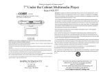
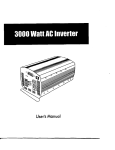
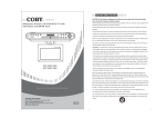
®
700/700SS
Computer Wheel Balancers
Service Manual and
Troubleshooting Guide
P.O. Box 3002, 1601 J. P. Hennessy Drive, LaVergne, TN USA 37086 615/641-7533 800/688-6359
HENNESSY INDUSTRIES INC. Manufacturer of AMMCO®, COATS® and BADA® Automotive Service Equipment and Tools.
Manual Part No.:
9111122
Revision: 01/01 rev. 1
Direct Drive
ii • Service Manual — COATS Models 700/700SS
Contents
Introduction . . . . . . . . . . . . . . . . . . . . . . . . .1
700 Wiring Diagram (Contactor Style) . . .17
Safety Notes . . . . . . . . . . . . . . . . . . . . . . . .1
700 Hood Installation Instructions
Servicing . . . . . . . . . . . . . . . . . . . . . . . . . . .1
Equipment Needed . . . . . . . . . . . . . . . . . . .1
Voltage Checking Procedure . . . . . . . . . . . .1
Preliminary Inspection . . . . . . . . . . . . . . . . .2
Functional Checks
Operational Check . . . . . . . . . . . . . . . . . . . . . . . .2
Accuracy Check . . . . . . . . . . . . . . . . . . . . . . . . . .3
Rotational Check . . . . . . . . . . . . . . . . . . . . . . . . .3
Calibration Procedures
Weight Sensor Calibration Procedure . . . . . . . . .3
Distance Gauge Tape Placement Procedure . . . . .3
Error Codes . . . . . . . . . . . . . . . . . . . . . . . . .4
Function Codes . . . . . . . . . . . . . . . . . . . . . .4
Troubleshooting Guide . . . . . . . . . . . . .5 - 12
Accuracy Problems . . . . . . . . . . . . . . . . . . . . . . .5
Rotational Problems . . . . . . . . . . . . . . . . . . . . . .6
Repeatability Problems . . . . . . . . . . . . . . . . . . . .7
Display Does Not Light . . . . . . . . . . . . . . . . . . . .8
Balancer Does Not Cycle . . . . . . . . . . . . . . . .9- 10
Balancer Does Not Brake . . . . . . . . . . . . . . . . . .11
Optical Encoder Checking Procedure . . . . . . . . .12
Before You Begin . . . . . . . . . . . . . . . . . . . . . . . .18
Parts Identification . . . . . . . . . . . . . . . . . . . . . . .18
Installation . . . . . . . . . . . . . . . . . . . . . . . . . . . . .18
*Solid State Balancers . . . . . . . . . . . . . . . .19
Piezo Output Checking Procedure . . . . . . . . . . .19
Motor Controller Test Box #8112078 . . . .20
Motor Controller PCB Diagram . . . . . . . . .21
*700 Wiring Diagram (Solid State Motor
Controller Model) . . . . . . . . . . . . . . . .22 - 23
*Troubleshooting Flow Charts (Solid State
*Motor Controller Model)
*Balancer Does Not Cycle . . . . . . . . . . . . . . . . .24
*Balancer Does Not Brake . . . . . . . . . . . . . . . . .25
*Glossary of Terms . . . . . . . . . . . . . . . . . .26
*This manual has been updated to include all related
models. Items that are new are high lighted by an
asterisk (*) for your convenience.
Replacement Procedures . . . . . . . . . .12 - 26
Front Panel/Printed Circuit Board Assembly . . . .12
Contactor Coil Resistance Measurement
Procedure . . . . . . . . . . . . . . . . . . . . . . . . . . . . . .12
Front Panel/Printed Circuit Board Assembly . . . .13
Touch Panel/Aluminum Back Panel and PCB
Assembly . . . . . . . . . . . . . . . . . . . . . . . . . . . . .13
On/Off Switch . . . . . . . . . . . . . . . . . . . . . . . . . .13
Circuit Breakers . . . . . . . . . . . . . . . . . . . . . . . . .13
Transformer . . . . . . . . . . . . . . . . . . . . . . . .13 - 14
Contactor . . . . . . . . . . . . . . . . . . . . . . . . . . . . .14
Distance Gauge Assembly . . . . . . . . . . . . . . . . .14
Rotary Shutter . . . . . . . . . . . . . . . . . . . . . . . . . .14
Optical Encoder Assembly . . . . . . . . . . . . . . . . .15
Drive Motor Assembly . . . . . . . . . . . . . . . . . . . .15
Piezo Assembly . . . . . . . . . . . . . . . . . . . . .15 - 16
Capacitor . . . . . . . . . . . . . . . . . . . . . . . . . . . . . .16
Service Manual — COATS Models 700/700SS • iii
Safety
IMPORTANT SAFETY INSTRUCTIONS
READ ALL INSTRUCTIONS
1.
Eye and face protection recommendations:
“Protective eye and face equipment is required to
be used where there is a reasonable probability of
injury that can be prevented by the use of such
equipment.” O.S.H.A. 1910.133(a) Protective goggles, safety glasses, or a face shield must be provided by the owner and worn by the operator of
the equipment. Care should be taken to see that
all eye and face safety precautions are followed by
the operator. ALWAYS WEAR SAFETY GLASSES.
Everyday glasses only have impact resistant
lenses, they are not safety glasses.
2. Do not disable hood safety interlock system, or in
any way shortcut safety controls and operations.
3. Be sure that wheels are mounted properly, the
hub nut engages the arbor for not less than four
(4) turns, and the hub nut is firmly tightened
before spinning the wheel.
4. Read and understand this manual before operating. Abuse and misuse will shorten the functional
life.
5. Be sure the balancer is properly connected to the
power supply and electrically grounded.
6. Do not operate equipment with a damaged cord
or if the equipment has been dropped or damaged
– until it has been examined by a qualified serviceman.
7.
Do not let cord hang over edge of table, bench, or
counter or come in contact with hot manifolds or
moving fan blades.
8. If an extension cord is necessary, a cord with a
current rating equal to or more than that of the
equipment should be used. Cords rated for less
current than the equipment may overheat. Care
should be taken to arrange the cord so that it will
not be tripped over or pulled.
10. Wear proper clothing. Safety toe, non-slip
footwear and protective hair covering to contain
hair is recommended. Do not wear jewelry, loose
clothing, neckties, or gloves when operating the
balancer.
11. Keep work area clean and well lighted. Cluttered
and/or dark areas invite accidents.
12. Avoid dangerous environments. Do not use power
tools or electrical equipment in damp or wet locations, or expose them to rain.
13. Avoid unintentional starting. Be sure the balancer
is turned off before servicing.
14. Disconnect the balancer before servicing.
15. Use only manufacturer’s recommended accessories. Improper accessories may result in personal injury or property damage.
16. Repair or replace any part that is damaged or worn
and that may cause unsafe balancer operation. Do
not operate damaged equipment until it has been
examined by a qualified service technician.
17. Never overload or stand on the balancer.
18. Do not allow untrained persons to operate
machinery.
19. To reduce the risk of fire, do not operate equipment in the vicinity of open containers or flammable liquids (gasoline).
20. Adequate ventilation should be provided when
working on operating internal combustion
engines.
21. Keep hair, loose clothing, fingers, and all parts of
body away from moving parts.
22. Use equipment only as described in this manual.
23. Use only manufacturer’s recommended attachments.
9. Keep guards and safety features in place and in
working order.
SAVE THESE INSTRUCTIONS
iv • Service Manual — COATS Models 700/700SS
Direct Drive
Introduction
This service manual contains the functional checks,
troubleshooting, adjustment, and part replacement
instructions for COATS® Models 700 Wheel Balancer.
Exploded views, illustrations, and an indexed parts list
facilitate parts location, ordering, and replacement. All
adjustments and replacements can be rendered with
mechanic’s or electrician’s tools.
Safety Notes
Equipment Needed
1. AC - DC/Volt - Ohm meter.
2. Test Wheel - Domestic 14" x 6" steel wheel with a
center hole suitable for mounting with a back cone. A
new 195/70-14 tire properly mounted and inflated, balanced to within 0.05 ounces should be part of this
wheel assembly. The lateral run out of this wheel should
be less than 1/8".
3. Mechanic’s and electrician’s tools.
High voltages, high torque motors, and high speed
rotating wheels are present in coats wheel balancers.
Follow the safety rules below while servicing a balancer:
4. Thread locking anaerobic (Loctite 242 or equivalent).
1. Disconnect balancer from power source before
starting any part replacement or internal adjustment.
6. Dial indicator (runout gauge) with magnetic base,
Starret No. 25-431 or equivalent.
2. Lower guard hood before starting cycle.
3. Do not wear neckties or loose clothing while servicing the balancer.
4. Be aware of hair length. If hair is long, wear it up
under a hat.
5. Retaining compound (Loctite 601 or equivalent).
7. Modeling Clay
Voltage Checking Procedure
1. Unplug the Balancer from the power source.
5. Mounting cones must be centered in wheel before
tightening. The wheel must be forced up firmly against
the faceplate.
2. Check the voltage between the terminals marked
“A” and “B”, shown in the diagram below, at the power
receptacle. The voltage should measure between 100
and 125VAC. If you measure no voltage, check the status of the circuit breakers that supply this power outlet.
The hub nut must be engaged by a minimum of four
(4) full threads. Tighten hub nut by rotating the wheel
and striking a spoke of the hub nut with the heel of the
hand. Failure to tighten the hub nut could result in serious injury.
3. Check from the power terminals to the ground terminal to verify a ground is present. The voltage measurement should be approximately 120V. Also measure
between the neutral terminal and the ground terminal.
The voltage measurement should be less than 0.5VAC.
Servicing
Note: If any faults are found in the above procedure, it is the responsibility of the owner.
COATS authorized service personnel are not
responsible for wiring within the building.
Service should be performed only by COATS® trained
and authorized service personnel the troubleshooting
and service procedures in this manual are arranged to
allow rapid and thorough service. The steps are preliminary inspection, functional checks, repair of failure,
replacement or adjustment, and functional check.
Identification of replacement parts required can be
accomplished by using the pictorial breakdown and
index in the parts list. It is important that the functional
checks be performed in sequence and the problem isolated prior to attempting any adjustments or replacements. If an adjustment or replacement is made, the
entire functional checks must be performed successfully before the balancer can be considered available for
service.
4. Plug the balancer to a power source.
5. Use an Ohmmeter to check the resistance between
the frame of the Balancer and the building ground. The
resistance should be less than 1 ohm. If the resistance
measurement is greater that 1 ohm, check the power
cord plug and frame connection for proper contact.
Ground
A
B
Green
White
Black
Service Manual — COATS Models 700/700SS • 1
Direct Drive
Preliminary Inspection
1. Check the power supply to the balancer. See the
procedure on page 1.
2. The Balancer should sit on all three (3) legs. Make
sure the legs have not filled with dirt, wheel weights, or
other foreign matter that may prevent a leg from making contact with the floor.
3. The floor should be a solid flat surface that does not
allow the balancer legs to set into a recess in the floor
or sink into the floor itself.
4. Inspect cones, hub nut, pressure cup(s), and
threaded stud for damage. Missing cones or accessories should be replaced.
Functional Checks
Operational Check
1. Turn the power switch ON. The display should read
as follows:
A,W,D
Weight Display
Mode
Grams/Ounces
-
_0.0
_.00
Dynamic
Last Selection
If the display fails to light, see DISPLAY DOES NOT
LIGHT on pg. 8.
2. Mount your test wheel (described in EQUIPMENT
NEEDED on pg. 1) on the balancer.
3. Enter the wheel parameter data.
Note: If this machine will not accept keypad
entries, replace the keypad. If this does not
correct the problem replace the PCB.
4. If the balancer is in round off mode, press and hold
the SHIFT key and press ROUND OFF to enter the nonround off mode.
5. If the balancer is in gram mode, press and hold the
SHIFT key and press GM/OZ key combination to set
the balancer to read in ounces.
6. Install a 4 oz. weight on the outer rim of the test
wheel.
7. Choose the DYNAMIC balancing mode.
8. Push the START button. The machine should now
cycle. If the machine does not cycle, see BALANCER
DOES NOT CYCLE on pages 9 - 10 or page 22.
9. The balancer should come up to speed, coast for
several revolutions, and then brake to a stop. If the
machine fails to brake and continues to coast, see BALANCER DOES NOT BRAKE on page 11 or page 23.
10. The balancer should now have weight values and
position lights displayed.
11. Position the wheel so the display for the center
position LED for the outside (right) plane is flashing.
12. Note the position of the 4 oz. weight and the
weight readings for both planes.
13. Perform five (5) spin cycles and note the positions
and weight readings after each spin cycle. The weight
readings should repeat within .2 oz and the position
within ± 1/2 inch. If they do not, see REPEATABILITY
PROBLEMS on page 7.
Note: If the customer had problems with a
specific wheel assembly only, make sure
there is no water or debris inside the tire.
2 • Service Manual — COATS Models 700/700SS
Direct Drive
Accuracy Check
1. Remove the 4 oz. weight from the wheel.
2. Fine balance the test wheel to obtain 0.00 (+0.02)
weight readings on both displays. It may be necessary
to use modeling clay to counter balance small imbalances.
3. Place a 4 oz. weight on the outside of the wheel.
4. Press start. The readings for this cycle should be as
follows:
Inner (Left) Plane
= 0.00 + 0.20 oz.
Outer (Right) Plane
= 4.00 + 0.05 oz.
Outer Position flashing = 4oz. at bottom dead center
± 1/2 inch
5. Move the 4 oz. weight to the inside plane. Press
start. The reading should be as follows:
Inner (Left) Plane
= 4.00 ± 0.05 oz.
Outer (Right) Plane
= 0.00 ± 0.20 oz.
Inner Position flashing = 4oz. at bottom dead center
± 1/2 inch
6. If the above results are not achieved check the A, W,
& D dimensions and perform WEIGHT SENSOR CALIBRATION procedure on page 3.
7. Check the placement of the distance tape, see the
DISTANCE GAUGE TAPE PLACEMENT PROCEDURE,
on page 3.
8. If specified results are not achieved see ACCURACY
PROBLEMS on page 5.
Rotational Check
1. Remove the 4 oz. weight from the inner rim and perform a fine balance to obtain 0.00 (+.02) weight readings
on inner and outer plane.
2. Position valve stem at 6 o’clock. Loosen hub nut just
enough to allow the wheel to move. While holding the
faceplate so it cannot turn, rotate the wheel 90 degrees
relative to the faceplate. Tighten hub nut.
3. Press START. Weight readings should be 0.30 oz. or
less.
4. Repeat steps 2 & 3. At 180 and 270 degrees weight
readings should be .30 oz. or less.
5. If the specified results are not achieved see ROTATIONAL PROBLEMS on page 6.
Calibration Procedures
Weight Sensor Calibration Procedure
1. Turn the power switch ON.
2. Mount the test wheel to the machine.
3. Enter the wheel parameters.
4. If the machine is in ROUND OFF mode, toggle it
OFF by pressing and holding the SHIFT key and pressing ROUND OFF.
5. If the machine is not in ounce mode put it into
ounce mode by pressing and holding the SHIFT key and
pressing GM/OZ.
6. Press and hold the SHIFT key and press CALIBRATE
to enter the calibration mode. The display should read
CAL 0.
7. Push the START button. The machine should now
cycle. This cycle is referred to as the zero spin cycle.
8. The balancer should come up to speed, coast for
several revolutions, and then brake to a stop.
9. The display should now read CAL 4.
10. Position the wheel so the display for the center
position LED for the outside (right) plane is flashing.
11. Add a 4 ounce weight to the 12 o’clock position on
the outside (right) of the wheel.
12. Push the START button.
13. The outer (right) weight display should read 4.00 ±
0.02 oz. and the center position L.E.D. for the outside
(right) plane should be flashing when the weight is at
bottom dead center.
Distance Gauge Tape Placement Procedure
If the ACCURACY CHECK fails, try entering an A
dimension .1 higher than the one used originally. If the
plane separation gets worse, try using an A dimension
.1 lower than the one used originally. If the plane separation gets better, keep increasing or decreasing the A
dimension until an acceptable value is achieved.
Calibrate the machine and perform the ACCURACY
CHECK. Repeat this procedure until the ACCURACY
CHECK produces an acceptable result. Move the distance tape to the position to allow proper A. Always perform calibration as the last step.
Service Manual — COATS Models 700/700SS • 3
Direct Drive
Error Codes
The following is a list of error codes. When the balancer is cycled several operating parameters are
checked. If one of these parameters is not within tolerance, the machine will generate one of the following
error codes and use the weight reading LEDs to display
the error code. An explanation of these codes and a
troubleshooting procedure follows each code.
Err Hub - This error occurs when the machine detects
a no “Ioad” condition on the motor at start up. If there
is a wheel mounted on the arbor, check the mounting of
the wheel to make sure it is not “slipping”. If it is see the
troubleshooting procedure for REPEATABILITY PROBLEMS.
Err Cal - This message is displayed when an error has
occurred during the calibration process. It can be caused
by not placing the calibration weight on the wheel for
the second spin or having the calibration weight on for
both spins. The code is generated by equal piezo outputs
in consecutive spins.
Err 1 - This message is displayed when the wheel
moves slowly when the start button is depressed. This
can be caused by a defective motor, defective contactor,
or incorrect wiring of either of the previous. See the
troubleshooting procedure for BALANCER DOES NOT
CYCLE.
Err 2 - Similar to Err 1, this message is displayed
when the time to reach measurement speed is too long.
See the troubleshooting procedure for BALANCER
DOES NOT CYCLE.
Err 3 - This error message is triggered by the lack of
encoder output when the start button is depressed. If
the drive motor did not start see the troubleshooting
procedure for BALANCER DOES NOT CYCLE. If the
drive motor does begin to spin see the OPTICAL
ENCODER CHECKING PROCEDURE.
Err 4 - This message is triggered when the machine
detects the wheel rotation in the reverse direction. See
the troubleshooting procedure for BALANCER DOES
NOT BRAKE.
Err 5 - This message is displayed when the time to
brake the wheel to a stop at the end of the cycle is too
long. See the troubleshooting procedure for BALANCER
DOES NOT BRAKE.
Err 6 - This message is displayed when there is no
power to the LEDs on the encoder. See the OPTICAL
ENCODER CHECKING PROCEDURE.
4 • Service Manual — COATS Models 700/700SS
Err 7 or Err 8 - One of these messages is displayed
when a time out occurs within the software on the PCB.
The most likely cause is 1) a defective encoder cable or
2) a defective PCB. Try replacing the components in that
order.
Err 9 - This message is displayed when the speed of
the wheel has decreased at too fast a rate. This could
occur if the machine is extremely cold and a small wheel
is mounted on the shaft.
Function Codes
50 - Code to escape from a continuous loop such as
when displaying the transducer output.
52 - Piezo output test, refer to PIEZO OUTPUT
CHECKING PROCEDURE.
Direct Drive
Troubleshooting Guide
The troubleshooting section of this manual makes use
of flow charts. These flow charts will enable you to more
quickly and accurately locate the problem with the balancer. The main topics covered by these flow charts are
ACCURACY PROBLEMS, ROTATIONAL PROBLEMS,
REPEATABILITY PROBLEMS, DISPLAY DOES NOT
LIGHT, BALANCER DOES NOT CYCLE, and BALANCER
DOES NOT BRAKE. These flow charts may refer you to
another section of the manual. If after a repair has been
completed you encounter another or similar problem,
refer to the section that best describes the problem currently encountered. The flow charts are designed to lead
you to the most likely problems towards the top of the
chart, where possible. HENNESSY INDUSTRIES hopes
this manual will help you provide the best and most thorough service to our customers.
The flow charts will refer to several voltage checks at
various points. To avoid lengthy and confusing charts, the
voltages shown on the blocks of the chart are nominal.
To better define these voltages see the range chart
below:
120VAC = 100 to 125VAC
24VDC = 22 to 32VDC
Accuracy Problems
Did you perform weight
sensor calibration?
No
Perform weight sensor calibration,
see Index for procedure.
Yes
Yes
Is weight reading
accurate?
No
Yes
Is position accurate?
Yes
Replace piezo sensors.
Did this correct problem?
No
Replace PCB Assembly,
see Index for procedure.
No
No
Replace optical encoder.
Did this correct the problem?
Yes
Return to FUNCTIONAL
CHECKS.
Service Manual — COATS Models 700/700SS • 5
Direct Drive
Rotational Problems
Is the test wheel balanced to
0.00 +.02 oz.?
No
Fine balance test wheel
and test again.
Yes
Is the balancer within ACCURACY
CHECK specifications?
Perform WEIGHT SENSOR CALIBRATION procedure or refer to ACCURACY
PROBLEMS flow chart and test again.
No
Yes
Are there burrs, dirt, and/or
grease on faceplate, test wheel,
cones, or pressure cup preventing perfect centering of the
wheel?
Yes
Remove burrs and dirt
and test again.
No
Are there worn or defective
cones, pressure cup, threaded
stud, backcone spring, or hub
nut?
Yes
Replace defective parts
and test again.
No
Using a dial indicator check the
runout on the mounting surface of the
motor faceplate & the runout of the
arbor shaft. Are either of the total
indicated runouts greater than .001?
Yes
No
Try mounting the wheel with a new
centering cone and spring. Does the
balancer now pass the rotational test?
No
Yes
Return to FUNCTIONAL
CHECKS.
6 • Service Manual — COATS Models 700/700SS
Replace drive motor, see
the procedure.
Test again.
Direct Drive
Repeatability Problems
Mark the wheel & faceplate with a
piece of chalk and check after each
spin. Is the wheel slipping
against the faceplate?
Clean the faceplate and/or remove all
nicks. Make sure wheel is chucked
tightly agoinst faceplate.
Yes
No
Is the hub nut broken or
the cones damaged?
Yes
Replace the damaged
part(s).
No
Is the balancer sitting on
a hard flat surface?
Move balancer to another
location in the shop.
No
Yes
Is the balancer located near a
piece of equipment that
causes the floor to vibrate?
Yes
No
Check the tension adjustment on the
motor springs. See the DRIVE MOTOR
REPLACEMENT PROCEDURE.
Where they adjusted properly?
No
Yes
Check the piezo wiring at the
piezo and at the PCB plug for
good connections.
Adjust springs. See step, 19 in the
DRIVE MOTOR REPLACEMENT
PROCEDURE.
Did this correct the problem?
Yes
No
Bad
Repair defective
connection(s).
Good
Replace piezos, see CHECKING
PROCEDURE before replacing.
Did this correct the problem?
Yes
No
Replace the optical encoder.
See Index for procedure.
Did this correct the problem?
Yes
Return to FUNCTIONAL
CHECKS.
No
Replace the PCB. See Index
procedure.
Did this correct the problem?
Yes
No
Replace the drive motor
assembly. See Index for procedure.
Service Manual — COATS Models 700/700SS • 7
Direct Drive
Display Does Not Light
Is the power switch set
to the ON position?
Turn the power
switch ON.
No
Yes
Is the proper voltage and ground
present at the receptacle? See
the checking AC Checking
procedure.
No
Have the voltage supply to
the machine corrected.
Yes
Has one of the 1A breakers on
the power panel tripped?
Yes
Reset the tripped breaker. If the breaker
trips again, replace the PCB.
No
Is there 120VAC between the
terminals marked 1 & 2 on the
transformer?
Yes
Is there 24VAC between
the terminals marked 7 & 8
on the transformer?
Replace the transformer, see the
Index for procedure.
No
Yes
No
Turn the power off and unplug the
machine. Check the continuity of
the 1A circuit breaker.
Checks
Bad
Checks
Good
Connect the machine to a power
source and turn the power switch
ON. Is there 24VAC between
pins 1 & 2 on the right most
connector of the PCB?
If the breaker is open, try
resetting and rechecking. If the
breaker remains open and does
not trip, replace the breaker.
Breaker
Trips
Replace the PCB. See Index
for procedure.
Yes
No
Check the continuity from pin 8 on the
transformer to pin 1 on the right most
connector of the PCB. Also check the
continuity from pin 7 on the transformer
to pin 2 on the same connector.
Checks
Good
Checks
Bad
Repair or replace the
defective wire or connection.
Checks
Bad
Is there 120VAC between
terminals 1 & 3 on the
reverse contactor?
Yes
No
Turn the power off and unplug the
machine. Turn the power switch to the
ON position. Check the continuity of the
wire from the terminal marked 2 on the
transformer to terminal 3 on the
reverse contactor.
Check the continuity of the wire
from the terminal marked 1 on the
transformer to terminal 1 on
the reverse contactor.
Checks
Bad
Check the continuity
of the power switch.
Is there 120VAC between
terminals 1 & 3 on the
forward contactor?
No
Yes
Replace or repair the defective jumper wire from the
forward to reverse contactor.
Checks
Good
Checks
Bad
Replace the power switch. See
Index for procedure.
Check the continuity of the
power cord from the terminals to
the appropritate connection on
the forward contactor.
8 • Service Manual — COATS Models 700/700SS
Checks
Bad
Repair or replace
the defective wire
or connection.
Direct Drive
Balancer Does Not Cycle
To use the following chart you will need a tire and wheel assembly mounted on the balancer, the hood closed,
and the proper A, W, and D dimensions entered. If you are unable to manually enter the proper wheel dimensions,
replace the touch panel.
Has one of the 1A circuit
breakers on the rear of the
machine tripped?
Yes
Reset the breaker & press
the start button.
Does Not Trips
Proceed to balance.
Trips
No
Turn the power switch OFF and unplug the machine.
Disconnect the white/violet wire from the forward
contactor, reset the breaker. Plug in the machine, turn
the power switch ON, & press the start button.
Trips
Replace the PCB.
See Index for
procedure.
Does Not Trips
Replace the contactor. See
Index for procedure.
Does the forward contactor
close when the start button
is depressed?
No
Is there 24VAC between
terminals 5 & 6 on the
transformer?
No
Replace the transformer. See
Index for procedure.
Yes
Yes
Turn the power switch OFF & unplug the
machine. Disconnect the wire from terminal
A2 of the forward contactor & check the
resistance between A1 & A2 of the contactor.
Is the resistance between 3 & 5 Ohms?
No
Replace the contactor. See
Index for procedure.
Yes
Disconnect the right most connector
on the PCB. Use an Ohmmeter to
check from A2 on the forward
contactor to terminal 5 on the
transformer. Connect the plug.
Less Than
1 Ohm
More Than 1 Ohm
Disconnect the wire from A1 on the
forward contactor. Use an Ohmmeter
to check continuity from A2 on the
forward contactor to A2 on the reverse
contactor. Connect the wire to
terminal A1 on the forward contactor.
More Than
1 Ohm
Disconnect the wire from A2 on the
forward contactor. Use an Ohmmeter to check continuity from A1 on the
forward contactor to terminal 5 on the
right most connector of the PCB.
Connect the wire to terminal
A2 on the contactor.
Less Than
1 Ohm
More Than
1 Ohm
Repair or replace defective wire from
A2 to A2 on the contactors.
Less Than 1 Ohm
Less Than
1 Ohm
Check the continuity of the 1A
circuit breaker attached to the
yellow wire.
Repair or replace defective wire
or connections.
More Than 1 Ohm
Repair or replace the circuit breaker,
see Index for procedure.
CONTINUED ON
NEXT PAGE
Service Manual — COATS Models 700/700SS • 9
Direct Drive
CONTINUED FROM
LAST PAGE
Is the proper voltage and
ground present at the
receptacle? See Index for
checking procedure.
No
Correct the voltage
supply to the machine.
Yes
Is there 120VAC between
No
terminals 1 & 3 on the
forward contactor?
Repair or replace defective
power cord or connections.
Yes
Is there 120VAC between
terminals 1 & 5 on the
forward contactor?
Is there 120VAC between
terminals 1 & 5 on the
reverse contactor?
No
Yes
No
Yes
Try replacing the capacitors. See
Index for procedure.
Manually close the forward
contactor & check for 120VAC
between terminals 2 & 4 and 2 & 6
of the forward contactor.
Voltage Not
Present
Replace the contactor.
See Index for procedure.
Voltage Present
Manually close the forward
contactor. Is there 120VAC between
terminals 2 & 4 and 2 & 6 on the
reverse contactor?
No
Repair or replace
jumper wire
connections.
Yes
Check connections at the wire
nut where the three motor
wires are joined.
Bad
Connection
Repair or replace
defective connection.
Good
Connection
Try replacing the capacitor.
See Index for procedure.
Motor Runs
Motor Does
Not Run
Replace defective
motor assembly.
See Index for procedure.
Return to
FUNC TIONAL CHECKS.
10 • Service Manual — COATS Models 700/700SS
Repair or replace defective
jumper wire or connections.
Direct Drive
Balancer Does Not Brake
Does the wheel rotate clockwise
when the forward contactor is
engaged?
No
Check the drive motor &
capacitor wiring.
Yes
Does the reverse
contactor ever close?
Does the reverse contactor
remain closed?
Yes
Yes
No
No
Has one of the 1A breakers on the
rear of the machine tripped?
No
Replace the optical encoder.
See Index for procedure.
Yes
Disconnect the wire from terminal A2
of the reverse contactor & check the
coil resistance from A1 - A2. Is the
resistance of the coil between 3 & 5
Ohms?
Turn the power switch OFF &
unplug the machine. Disconnect
the wire from A2 on the brake
contactor. Use an Ohmmeter to
check continuity from A1 on the
reverse contactor to terminal 4 on
the right most connector of the
PCB connect the wire to
terminal A2 on the contactor.
Is there a 120VAC between
terminals 1 & 3 and 1 & 5 on
the reverse contactor?
More Than
1 Ohm
Less Than
1 Ohm
No
Yes
Replace the contactor. See Index
for procedure.
Replace the PCB. See
Index for procedure.
Repair or replace
defective wire or
connection.
Replace the PCB. .
See Index for
procedure.
No
Repair or replace the defective
jumper wire or connections.
No
Replace the contactor.
See Index for procedure.
Yes
Manually close the reverse
contactor. Is there a
120VAC between terminals
2 & 4 and 2 & 6?
Yes
Check the connections from
the contactor to the motor.
Bad
Repair or replace the defective
wire or connections.
Good
Replace the drive motor.
See Index for procedure.
Service Manual — COATS Models 700/700SS • 11
Direct Drive
Replacement Procedures
Optical Encoder Checking Procedure
1. When reading the voltages on the white & green
wires, turn the faceplate slowly by hand. The low voltage must be less than .7VDC. The high voltage must be
greater than 4.OVDC.
2. Voltage readings are taken with all optical encoder
wires connected.
LEAD COLOR
GREEN to VIOLET
YELLOW to VIOLET
BLUE to VIOLET
VIOLET
-
VOLTAGE
2.4 ± .5VDC
Less than .7VDC; greater than 4VDC
Less than .7VDC; greater than 4VDC
GROUND
Forward Relay
A1 to A2
Reverse Relay
A1 to A2
Neutral (off)
O VAC
O VAC
Start
20-30 VAC
O VAC
Coast
O VAC
O VAC
Stop
O VAC
2O-30 VAC
Contractor Coil Resistance:
A1 to A2 = 4 ohms ± 1 ohm
(6 ohms on new contactor)
The procedures in this section will aid in replacing
major sub-assemblies of the balancer.
Do not disassemble, adjust or replace any part before
performing the PRELIMINARY INSPECTION and FUNCTIONAL CHECK PROCEDURES. These procedures,
along with the troubleshooting flow charts, will isolate
the necessary adjustment or replacement. Perform
checks in the order listed and exactly as specified.
Refer to the illustrated parts breakdowns and parts
lists for parts identification. Standard commercial fittings and fasteners are used throughout and should be
obtained locally.
Check all interconnecting wiring and connectors when
an electrical malfunction is indicated. Check all fittings
and fasteners when a mechanical malfunction is indicated.
Front Panel/Printed Circuit Board Assembly
Important: Never replace the printed circuit
board without first checking the contactor
coil resistance whenever any of the following symptoms occur. Shorted contactor coils
will result in failure of the new printed circuit
board.
1. Displays do not light.
2
1
4
3
6
Reverse
A2 14
A1
2. Drive motor does not start.
3. Drive motor does not stop.
5
Contactor Coil Resistance Measurement
Procedure
13
1. Unplug the balancer.
2
4
6
A2 14
1
Forward
A1
3
5
13
2. Disconnect the plug from the right side of printed
circuit board assembly.
3. Set ohmmeter to lowest scale.
4. Measure the resistance from terminals Al to A2 on
both the start and brake contactors.
5. Resistance should be 3 to 5 ohm (5 to 7 ohm on
new contactor), if not, replace the contactor.
Note: If shorted contactor coils were found
DO NOT reinstall the old printed circuit
board after the new contactor has been
installed.
NEW REPAIR PROCEDURE: The model 700 is different from other COATS® balancers in that the Front
Panel/Printed Board assembly has been designed so
that the PCB Assembly and the Touch Panel Aluminum
Back Panel can be replaced separately. Refer to the
Troubleshooting Guide section for diagnostic instructions for isolating the defective assembly.
12 • Service Manual — COATS Models 700/700SS
Direct Drive
Front Panel/Printed Circuit Board Assembly
1. Unplug the balancer.
2. Check contactor coil resistances, see the procedure above.
3. Remove the six (6) 1/4" self tapping screws and
remove the weight tray.
4. Remove the four (4) 6-32 Phillips screws holding
the Front Panel/Printed Circuit Board Assembly to the
power panel.
5. Disconnect the plugs on the PCB Assembly.
6. Remove the Front Panel/Printed Circuit Board
AssembIy.
7. Connect the plugs to the new PCB Assembly.
8. Line up the four (4) 6-32 studs on the back of the
Touch Panel/Aluminum Back Panel with the four (4)
holes in the power panel and install the four (4) 6-32
Phillips screws.
On/Off Switch
1. Unplug the balancer.
2. Remove weight tray.
3. Disconnect wiring to on/off switch.
4. Squeeze the retainers at the top and bottom of the
switch and push it through the opening in the power
panel and chassis.
5. Install new on/off switch.
6. Connect wires.
7. Install the weight tray (1/2" long screws on top) and
plug in balancer.
8. Perform the FUNCTIONAL CHECKS.
Circuit Breakers
There are two (2) circuit breakers located on the top of
the Power Panel. Refer to the Wiring Diagrams for circuit breaker location. The replacement procedure for
each is the same.
9. Install the weight tray (1/2" long screws on top) and
plug in balancer.
1. Unplug the balancer.
10. Perform the Weight Sensor Calibration Procedure.
2. Remove weight tray.
11. Perform the FUNCTIONAL CHECKS.
3. Disconnect wiring to circuit breaker.
Touch Panel/Aluminum Back Panel and PCB
Assembly
1. Unplug the balancer.
2. If the PCB is being replaced, check contactor coil
resistances, see the procedure on page 12.
3. Remove Front Panel/PCB Assembly from the
power panel.
4. Remove the eight (8) screws holding the PCB
Assembly to the Touch Panel/Aluminum Back Panel.
4. Squeeze the retainers on both sides of the circuit
breaker and push it through the power panel and chassis.
5. Install new circuit breaker.
6. Connect wires.
7. Install the weight tray (1/2" long screws on top) and
plug in balancer.
8. Perform the FUNCTIONAL CHECKS.
Transformer
5. Disconnect the plugs going to the PCB Assembly.
1. Unplug the balancer.
6. Replace the defective Touch Panel/Aluminum Back
Panel or PCB Assembly and connect: the plug from the
Touch Panel/Aluminum Back Panel to the PCB
Assembly.
2. Remove weight tray.
Note: Make sure there are no twists or kinks
in the touch panel cable.
7. Install the eight (8) screws holding the PCB assembly to the Touch Panel/Aluminum Back Panel.
8. Install Front Panel/PCB Assembly to the power
panel.
3. Remove the two (2) 8-32 x 1/2 screws and the two
(2) 8-32 nuts and remove the transformer from the
Power Panel.
4. Record wire color and corresponding transformer
terminal numbers.
5. Disconnect wiring to old transformer.
6. Connect wiring to the new transformer.
(Continued on the next page.)
9. Install the weight tray (1/2" long screws on top) and
plug in balancer.
10. Perform the FUNCTIONAL CHECKS.
Service Manual — COATS Models 700/700SS • 13
Direct Drive
CAUTION
Transformer wiring must be transferred to
new transformer exactly as connected previously. Failure to perform this important step
properly may result in damage to transformer, balancer wiring, or printed circuit
board. (See Interconnection Diagram).
7. Install new transformer to Power Panel.
8. Install the weight tray (1/2" long screws on top) and
plug in balancer.
9. Perform the FUNCTIONAL CHECKS.
Distance Arm Assembly
1. Unplug the balancer.
2. Remove weight tray.
3. While holding the spring, Remove the 1/4" Self
Tapping screw, 3/8" lock washer, and flat washer at the
end of the distance arm.
4. Hold the spring and slide the distance gauge out of
the balancer.
5. Install the new distance arm.
6. Install the 1/4" Self Tapping screw, 3/8" lock washer,
and flat washer at the end of the distance arm and
tighten.
3. Remove the Front Panel/Printed Circuit Board
Assembly from the power panel.
Note: If you let go of the spring follow these
steps. To tighten the distance arm spring,
rotate the spring stop clockwise two revolutions (when viewed from distance gauge
arm) and locate spring stop against distance
bracket.
4. Disconnect the three (3) plugs from the Printed
Circuit Board Assembly.
7. Perform DISTANCE GAUGE TAPE PLACEMENT
PROCEDURE on page 10.
5. Remove three (3) 6-32 x 1/2 screws holding power
panel to chassis and set power panel on top of bracket
in center of balancer to facilitate removal.
8. Install the weight tray (1/2" long screws on top) and
plug in balancer.
6. Record the wire numbers and the corresponding
contactor terminal location.
Rotary Shutter
Contactor
1. Unplug the balancer.
2. Remove weight tray.
7. Disconnect wires at contactor.
8. Loosen (but do not remove) two (2) 8-32 x 3/4
screws holding contactor and slide out contactor,.
9. Install new contactor aid connect wiring.
CAUTION
Contactor wiring must be transferred to new
contactor exactly as connected previously.
Failure to perform this important step can
result in damage to contactor, drive motor,
balancer wiring and printed circuit board.
(See Interconnection Diagram).
Note: For ease of installation, the motor
wires are numbered corresponding to the
motor terminal numbers on the wiring diagram.
10. Install Power Panel.
11. Install the weight tray (1/2" long screws on top)
and plug in balancer.
12. Perform the FUNCTIONAL CHECKS.
14 • Service Manual — COATS Models 700/700SS
9. Perform FUNCTIONAL CHECKS.
1. Unplug the balancer.
2. Remove weight tray.
3. Remove the encoder cover inside the rear of the
motor end bell.
4. Remove the shoulder bolt and the rotary shutter.
Note: Some motors will have a plastic shim,
part number 8-143988 between the rotor
and the rotary shutter. Leave this shim in
place when replacing the rotary shutter.
5. Install the new rotary shutter.
6. Put Loctite 242 or equivalent on the shoulder bolt
threads, install and tighten.
7. Install the encoder cover.
8. Install the weight tray (1/2" long screws on top) and
plug in balancer.
9. Perform the FUNCTIONAL CHECKS.
Direct Drive
Optical Encoder Assembly
1. Unplug the balancer.
2. Remove weight tray.
3. Remove the encoder cover inside the rear of the
motor end bell.
4. Remove rotary shutter.
5. Disconnect optical encoder plug.
12. Clean and apply Loctite to the surface of the flex
plate and the cradle where they mate.
13. Apply Loctite 242 to the threads of the 3/8-16
washer head screws and install the flex plate on the
cradle.
14. Ensure balls are inserted into each piezo assembly.
15. Install motor.
6. Remove the optical encoder through the hole in
the aluminum rear end bell casting.
16. Install 5/16-18 X 1 washer head screws and four
(4) washers while holding flex plate to chassis.
Note: Some motors will have a plastic shim
behind the optical encoder. Install this shim
in place when replacing the optical encoder.
17. Install piezo springs, piezo retainers and 3/8-16
nyloc nuts.
7. Install new optical encoder.
8. Install rotary shutter.
18. Tighten the nyloc nuts until the distance from the
top of the motor cradle to top of the piezo spring
retainer is 2 inches.
9. Install rear end bell cover.
19. Connect optical encoder plug.
10. Connect optical encoder plug.
20. Connect drive motor wires to the contactor.
11. Install the weight tray (1/2” long screws on top)
and plug in balancer.
12. Perform the FUNCTIONAL CHECKS.
Drive Motor Assembly
The model 700 is different from other Coats balancers
in that the spring loading is done from the top making
motor replacement and piezo spring adjustment easier.
Note: Each motor wire is numbered corresponding to the motor terminals on the
wiring diagram.
21. Install the weight tray (1/2" long screws on top)
and motor gasket and pIug in the balancer.
22. Perform the FUNCTIONAL CHECKS.
Piezo Assembly
1. Unplug the balancer.
1. Unplug the balancer.
2. Remove weight tray and motor gasket.
2. Remove weight tray and motor gasket.
3. Disconnect optical encoder plug.
4. Disconnect each motor wire where it is connected
to the contactor.
5. Remove the four (4) piezo springs and piezo spring
retainers.
6. Remove the two (2) 5/16-18 X 1 washer head
screws, four (4) washers, and lift out the motor assembly.
7. Position the motor on its side or back and remove
the four (4) 3/8-16 washer head screws holding the flex
plate to the motor.
8. Remove the flex plate.
9. Remove the four (4)3/3-16 washer head screws
holding the cradle to the motor.
10. Remove the cradle from the motor.
11. Apply Loctite 242 to the threads of the 3/8-16
washer head screws and install the cradle on the new
motor.
3. Remove the four (4) 3/8-16 Nyloc spring retaining
nuts, spring retainers and piezo springs.
4. Remove the two (2) 5/16-18 X 1 washer head
screws.
5. Disconnect the optical encoder plugs.
6. Note wire colors and disconnect wires to piezo
assemblies.
7. Lift up on the motor and twist and lift the piezo
assemblies to remove from the chassis.
Note: The piezo assemblies used in the
model 700 balancer are different from other
Coats balancers in that they are held in position by studs in the bottom of the piezo carriers that fit into holes in the chassis.
8. Use emery cloth to clean the mounting surfaces of
the piezo assemblies and chassis, install new piezo
assemblies and connect wires.
9. Install the two (2) 5/16-18 X 1 washer head screws.
Service Manual — COATS Models 700/700SS • 15
Direct Drive
10. Install piezo springs, spring retainers and Nyloc
nuts.
11. Tighten the Nyloc nuts until the distance from the
top of the motor cradle to the top of the retainer is two
(2) inches.
12. Connect the optical encoder plugs.
13. Install motor, weight tray (1/2" long screws on
top), and motor gasket and plug in balancer.
14. Perform the FUNCTIONAL CHECKS.
Capacitor
1. Unplug the balancer.
2. Remove weight tray.
3. Remove the power panel.
4. Remove the capacitor from the capacitor bracket.
5. Remove the capacitor end caps. Note wire locations, disconnect wires from capacitors and transfer
wires to new capacitors.
Note: Only one capacitor should have a
resistor connected across its terminals. If
both new capacitors have resistors, cut one
out.
6. Install the capacitor.
7. Install the power panel.
8. Install weight tray (1/2° long screws on top) and
plug in balancer.
9. Perform PRELIMINARY INSPECTION and FUNCTIONAL CHECKS.
16 • Service Manual — COATS Models 700/700SS
Direct Drive
700 Wiring Diagram (Contactor Style)
Service Manual — COATS Models 700/700SS • 17
Direct Drive
700 Hood Installation Instructions
1. Unplug the balancer from electrical outlet.
Before You Begin
These installation instructions are intended for use
with a properly installed and operational COATS Model
700 balancer only. Do not attempt to install this hood kit
on any other balancer.
Parts Identification
Use this exploded view diagram to assist with
assembly and installation. Note that items 1, 2, and 3
are factory assembled in the original kit shipment.
PART
NO.
QTY.
8308818 1
8106301 4
8309818 1
8308062 1
8109945 1
8109944 1
8307014 2
8143826 1
8106302 3
8106303 3
8301122 1
8309008 1
8301121 1
8301120 1
ITEM
1
2
3
4
5
6
7
8
9
10
11
12
13
14
Installation
DESCRIPTION
Hood
Screw
Bar, Hood
Spring, Hood
Retainer, 1.5"
Washer, Hood Bar
Bearing, Nylon
Bracket, Hood
Screw, 3/8-16x0.875
Nut, 3/8-16 Whiz Lock
Nut, 1/2-13 Nyloc, Hex
Stop, Hood, Rubber
Washer, 1/2x1.4
Bolt, 1/2-13x2-1/2 HHCS
2. Remove the weight tray by removing 6 screws (2
on each: left side, right side, top above control panel).
3. Place the hood bracket against the rear of the balancer. Make sure the holes on the bracket align with
their companion holes on the rear of the balancer.
4. Attach the bracket to the balancer with the 7/8"
screws and matching nuts. Insert the screws from the
inside of the balancer, through the rear of the balancer,
and through the bracket. Tighten securely.
5. Assemble the hood stop by sliding the washer and
then the rubber hood stop onto the 2-1/2" long bolt.
6. Insert the threaded end of the hood stop bolt
through the hole in the side of the bracket and secure
it in place with the 1/2" nyloc nut.
7. Insert one nylon bearing into each of the large
holes at the end of the bracket. Push them in until the
flange of the bearing sits flat against the bracket.
8. Slide the hood bar through the nylon bearings.
Note: You will have to hold the hood assembly at a partially raised position so that the
cam on the hood bar clears the rubber hood
stop. When properly assembled, the cam
will be positioned directly above the rubber
hood stop and will contact the stop in the
fully raised and fully lowered positions.
9. Slide the hood bar washer over the hood bar.
10. Push the retainer ring onto the hood bar.
11. Hook the elongated end of the spring into the
hole on the edge and midway up the rear of the balancer.
1
CAUTION
2
Use help to hold the hood up while attaching the
spring. This will prevent sudden, unintentional lowering
of the hood which could cause personal injury.
6
5
7
7
12. With the hood held up, place the hook on the
other end of the spring over the grooved pin on the
hood bar cam. Seat the hook in the groove.
8
9
11 12 13
13. Reposition the weight tray and secure in place
with the 6 screws.
14
10
3
4
18 • Service Manual — COATS Models 700/700SS
Remember: The 1/2" long screws go in the
holes on the top of the weight tray.
Direct Drive
*Solid State Balancers
In January of 1998 Hennessy began building balancers with a new Solid State Motor Controller. For
troubleshooting and repair of that portion of the balance refer to the table of contents, the appropriate
wiring diagram, and the troubleshooting guide.
Piezo Output Checking Procedure
The piezo out-put test can be used to help diagnose
problems or failures with piezos on the 6401, 950/1050,
1025 (Limited Edition), 850, and 700 balancers. When
the test is activated the weight display will show four
different readings as the Dynamic, RV, Alloy 1, and Alloy
2 LED’s alternately light up. The values needed are the
Dynamic (1st LED) and Alloy 1 (3rd LED). Dynamic
value is the amplitude, or signal strength, of the left
piezo. Alloy 1 is the amplitude of the right front and rear
piezo added together (except for 850 that only has two
piezos). It is the consistency of the readings through
five or six spins that is important, not the value of the
readings.
To use the codes perform the following steps:
1. Mount a balanced wheel on the balancer with a 4oz. weight (8 oz. for 6401) on the outside. Enter the
wheel parameters.
7. If the reading is stable the right front piezo is good.
Check and/or replace the right rear piezo after testing.
8. If the reading in step #7 fluctuates, check and/or
replace the right front piezo.
9. Reverse steps #6 and #7 to test the right rear
piezo. Both piezos should be checked individually
before replacing either piezo.
Note: Rust, corrosion, and trash under the
piezo ball or between the piezo and the
chassis can cause a bad ground and make
the readings fluctuate. Cleaning, reinstallation, adjusting to proper torque and calibrating may be all that is necessary for
repair.
Note: For 850 use the Dynamic LED for the
left reading and the Static LED for the right
reading.
For the 700 balancer use the Dynamic LED for the left
and Alloy LED for the two right piezos.
When checking these two balancers only use the left
display readings (rounded off to 3 places).
Code 52 (Shift 0 - 52)
6401, 950/1050, 1025, 700
Code 27
850
2. Enter the piezo test code for the model balancer
being tested. Ignore the initial set of values displayed.
3. Spin the wheel by closing the wheel guard and/or
pressing the spin button. When the balancer stops,
write down the values when the Dynamic and Alloy 1
LED’s (Truck Dyn & RV Dyn for 6401) are on. These values will be slightly different on each balancer. Typical
readings for 950/1050 balancer - Left Display 1150,
Right Display 1050 (L - 3430, R - 2450 for 6401 with an
8 oz weight).
4. Repeat step 3 above for five more spins.
Remember you are looking for consistency of the readings.
5. If the Dynamic value fluctuates more than +/- 10,
check and/or replace the left piezo.
Note: The following steps will allow both
right piezos to be tested individually by
unplugging one at a time.
(The 850 only has two piezos and may be tested by
reading the left and right output when the Dynamic and
Static LED's are on. For 700 and 850 use the values in
the left weight display, ignore the right display.)
6. If the Alloy 1 reading fluctuates more than +/- 10
test the right front piezo by unplugging the right rear
piezo and repeating step 4.
Service Manual — COATS Models 700/700SS • 19
Direct Drive
Motor Controller Test Box #8112078
CONTROL
SIGNAL
FORWARD
SPIN
In-line "Control Signal"
Detection
Forward and
Reverse "Control"
Output
Solid State
Motor Controller
PCB
DETECT
CONTROL
SIGNAL
FORWARD
SPIN
DETECT
STOP
REVERSE
ON
MOTOR
CONTROLLER
Forward
Control
Reverse
Control
ON
Mode 1
Forward and Reverse
buttons are used to
control signals
to the Solid State
Motor Control PCB.
Solid State
Motor Controller
PCB
In-line Signal
Detector
Indicator LEDs
REVERSE
OFF
HENNESSY INDUSTRIES,INC.
STOP
MOTOR
CONTROLLER
HENNESSY
CPU
Control Out
OFF
Power
Indicator
Power
Switch
INDUSTRIES,INC.
Solid State
Motor Controller
PCB
WARNING
CONTROL
SIGNAL
FORWARD
SPIN
DETECT
CONTROL
SIGNAL
FORWARD
SPIN
STOP
REVERSE
DETECT
STOP
REVERSE
ON
MOTOR
CONTROLLER
OFF
HENNESSY INDUSTRIES,INC.
Mode 2
A Loop-back plug
is connected from
the Control Output
back to the Signal
Detection input to
monitor the Control
Signal output of the
Diagnostic Tool while
manually applying the
control signal.
ON
MOTOR
CONTROLLER
OFF
HENNESSY INDUSTRIES,INC.
Mode 3
The Diagnostic Tool
is connected in-line
with the control cable
from the CPU Motor
Control output to give
an indication of the
Control signal.
20 • Service Manual — COATS Models 700/700SS
**HAZARDOUS VOLTAGES ARE
PRESENT WITHIN THE BALANCER!**
**USE CAUTION WHEN
WORKING ON LIVE EQUIPMENT!**
**BE PREPARED TO DISCONNECT
POWER FROM THE BALANCER!**
Component failure within the MOTOR
CONTROLLER diagnostic box could
result in catastrophic failure of the
Solid State Motor Controller PCB!
**DO NOT ALLOW THE WHEEL
TO REACH EXCESSIVE SPEEDS!**
An unbalanced wheel could cause
the balancer to become unstable.
Direct Drive
Motor Controller PCB Diagram
Service Manual — COATS Models 700/700SS • 21
Direct Drive
*700 Wiring Diagram (Solid State Motor Controller Model)
22 • Service Manual — COATS Models 700/700SS
Direct Drive
Service Manual — COATS Models 700/700SS • 23
Direct Drive
*Troubleshooting Flow Charts (Solid State Motor Controller Model)
*Balancer Does Not Cycle
To use the following chart you will need a tire and wheel assembly mounted on the balancer, the hood closed,
and the proper A, W, and D dimensions entered. If you are unable to manually enter the proper wheel dimensions,
replace the touch panel.
Tur n balancer on.
Press spin
(balancer must
display info. to
proceed.)
Does motor buzz
or try to turn?
Connect
MC test box to
MC PCB. Does
motor spin?
No
Ye s
Ye s
Is AC correct to T1
of MC PCB?
Plug RJ11
from Main PCB into
MC test box. Does
motor spin?
Replace MC PCB.
No
Troubleshoot AC.
No
To make this check, use the
MC test box to activate the
spin voltage during test.
Ye s
Ye s
Is AC correct on
Motor connection of
MC PCB?
Do location
LEDs move when
wheel is rotated?
Ye s
Ye s
Check wiring to motor.
Replace motor.
Replace Main PCB.
No
Check wiring
connection on P4.
Check/replace
capacitors.
Replace MC PCB.
24 • Service Manual — COATS Models 700/700SS
No
No
Repair/replace the
control cable
Troubleshoot
Encoder system
MC = M otor Controller.
MC Test Box # 8112078
Direct Drive
*Balancer Does Not Brake
Balancer must spin
and displaying
infor mation to
proceed.
Does an error
message appear?
Ye s
Does wheel
attempt to stop?
Ye s
No
Cross reference
error message to
table and
troubleshoot from
the given location.
Do
readings appear
on display after
wheel has
stop?
No
Ye s
Use MC test box,
will motor spin &
stop?
No
Test control cable.
Replace Motor
Controller
Ye s
MC = M otor Controller.
No
Test control cable.
Replace the Main
P C B.
MC Test Box # 8112078
Service Manual — COATS Models 700/700SS • 25
Direct Drive
*Glossary of Terms
Accuracy Check - Also refereed to as Plane
Separation. When a weight is placed on one side
(plane) of a wheel the opposite side (plane) should not
change.
Balancer Calibration - Also know as Weight Sensor
Calibration. This process uses a specified size wheel
and a 4 oz. weight to make sure the balancer giving the
correct reading.
Distance Gauge Tape Placement - Also know as
Optimizing A. If there is a problem with the accuracy
check this is the procedure to correct the problem.
Balancer calibration is needed after this procedure.
Hub Centric Wheel - A wheel that is centered to the
axle by the center hole in the wheel.
Lug Centric Wheel - A wheel that is centered to the
axle by the lug bolts.
Rotational Check - This is a procedure to verify if
there is a problem in the balancer or the mounting of
the wheel. This should be done with a Hub Centric
wheel.
26 • Service Manual — COATS Models 700/700SS
Direct Drive
Notes
Service Manual — COATS Models 700/700SS • 27
9111122 01/01 rev. 1
© Copyright 1997 Hennessy Industries and COATS
All Rights Reserved
Printed in USA