1
Service Manual
Household Sewing
Machine
2802/2852 2808/2858
2809/2859 2818/2868
THE SINGER COMPANY
2005 SINGER BRASIL
SEWING MACHINE CO., LTD.
ALL RIGHTS RESERVED
Registered Trademark “THE SINGER COMPANY LTD.”
Printed In Brazil
358487-001
Mar./2005
Service Manual
Revisions Records
Revision
Rev. no.
Description
01
Approval
and date
358487-001
Mar./2005
Service Manual
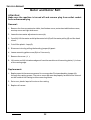
This manual is designed for use by trained and qualified service persons.
The SINGER COMPANY will not be responsible for any parts requiring
replacement due to natural wear or to the abuse or negligence of its use
or in the event the machine is serviced by other than a trained and
qualified service person or even if replaced parts do not meet applicable
specifications.
Rev. no.
02
358487-001
Mar./2005
Service Manual
General Information
Scope
This service manual describes all of the servicing procedures,including all adjustments and parts
removal and replacement for the 2802/2852, 2808/2858, 2809/2859 and 2818/2868 models
machine. Additional information covering any production changes, improvements or changes to
parts will be made by issuing Singer service/parts bulletins.
Machine Description
lTubular and flat bed.
lLightweight “Duratec” casting.
lApollo sewing system.
lElectronic triac foot speed controller.
lNew "FT" fabric feed system.
lVertical needle profile.
lMotor concealed in bed.
lHorizontal spool pin.
lAuto declutching bobbin winding.
lBobbin capacity of 41 m (45 yds) minimum.
lUniversal presser bar pressure control.
lMaximum stitch lenght 5 mm (5 s.p.i.).
lSelf-threading take-up lever.
lPush button instant reverse.
lOne-way needle insertion.
lDirect pattern selection.
lBed length 380 mm. (14.96 inches) without cloth plate.
lBed width 185 mm. (7.28 inches).
lBed height 83 mm. (3.27 inches).
lClearance under free arm 25,4 mm. (1.0 inch).
lFree arm circunference 264 mm. (10.39 inches).
lOverall height 310 mm. (12.20 inches).
lWeight 7,0 kg. (15,3 lbs).
Tool requirements
l1/8" screwdriver
l3/16" screwdriver
l1/4" screwdriver
lExtralong screwdriver (5,0 mm dia. x 380 mm long)
lPhilips screwdriver
l8 mm. open end wrench
l10 mm. open end wrench
lPliers
lWire-cutter pliers
lFeeler gauge GM8092
lFeeler gauge set.
l1,5 mm Allen wrench
lStraight tips external ring pliers (tip dia. 0,9 mm)
“Duratec” Casting
With the introduction of “Duratec”, selfthreading screws have been used to mount many of the
parts and assemblies to the structure. If is important that when replacing these screws, they be
threaded into the original screw threads. The proper procedure for doing this is to insert the
screw into the hole and turn the screw conterclockwise until the screw can be felt to “drop” in
place. An audible “click” may also be herad. Once the screw is properly in place, it may then be
tightened.
Rev. no.
03
358487-001
Mar./2005
Service Manual
Table of Contents
Section 1
PAGE
l
l
l
l
l
l
l
l
l
l
l
l
l
l
l
l
l
l
l
l
l
l
l
l
l
Parts removals and replacements......................................................... 06
Face plate..................................................................................... 07-08
Light bulb replacement..................................................................... 07-08
Arm top cover................................................................................ 09-10
Bed bottom cover and end cover.......................................................... 11-12
Needle bar..................................................................................... 13-14
Head end assembly........................................................................... 15-16
Take-up lever assembly and needle bar connecting link.............................. 17-18
Handwheel and shaft driver assembly.................................................... 19-20
Cam stack......................................................................................21-22
Disc follower quick out lever................................................................23-24
Disc follower....................................................................................23-24
Arm shaft and horizontal bevel gear.......................................................25-26
Pattern selector assembly ..................................................................27-28
Thread tension assembly.................................................................... 29-30
Motor and motor belt........................................................................31-32
Hook............................................................................................ 33-34
Feed lifting lever assembly................................................................. 35-36
Feed rock shaft assembly................................................................... 37-38
Feed forked connection..................................................................... 39-40
Vertical shaft bevel gear.................................................................... 41-42
Vertical shaft.................................................................................. 43-44
Stitch lenght control assembly............................................................. 45-46
Pattern selector mechanism................................................................ 47-48
Needle position selector lever..............................................................49-50
Rev. no.
04
358487-001
Mar./2005
Service Manual
Table of Contents
Section 2
l
l
l
l
l
l
l
l
l
l
l
l
l
l
l
l
l
l
l
l
l
l
l
l
l
l
l
l
l
l
l
l
PAGE
Sequential order of adjustment procedures ...............................................
51
Vertical shaft end play .........................................................................
52-53
Bevel gear mesh and arm shaft end play ..................................................
54-55
Disc and disc follower clearance ........................................................56-57
Cam stack radial play .....................................................................56-57
Take-up lever and needle bar connecting link lost motion .............................
58-59
Needle bar bearings ...........................................................................
60-61
Needle bar height ..............................................................................
62-63
Needle bar pendulum timing ...............................................................
64-65
Zig-zag centralizing procedure ..............................................................
66-67
Needle location in the needle plate slot ..................................................
68-69
Needle to hook relationship ..................................................................
70-71
Maximum width zig-zag lever stop.........................................................
72-73
Needle bar safety bight stop (left side) ..................................................
74-75
Presser bar height and alignment ...........................................................
76-77
Hook drive belt tension .....................................................................
78-79
Hook timing (hook and needle synchronism) ............................................
80-81
Bobbin case position finger .................................................................
82-83
Bobbin case position plate .................................................................
82-83
Bobbin case clearance .......................................................................
84-85
Needle Thread tension .......................................................................
86-87
Bobbin winder .................................................................................
88-89
Feed rock shaft end play ....................................................................
90-91
Feed dog centralization .....................................................................
92-93
Feed dog height ..............................................................................
92-93
Feed dog throw ...............................................................................
94-95
Stitch length regulator spring tension...................................................96-97
Motor belt tension ...........................................................................
98-99
Zero feed ....................................................................................100-103
Lubrication....................................................................................
104-108
Flexi stitch zeroing..........................................................................109-110
Buttonhole cutting space..................................................................111-112
Rev. no.
05
358487-001
Mar./2005
Service Manual
Section 1
Parts Removal and
Replacement
Rev. no.
06
358487-001
Mar./2005
Service Manual
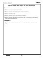
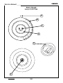
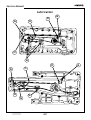
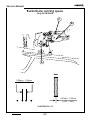
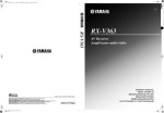
Face Plate Cover
B
A
Light Bulb Replacement
C
Rev. no.
07
358487-001
Mar./2005
Service Manual
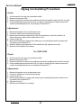
Face Plate Cover
Removal:
1. Raise presser foot.
2. Remove face plate cover screw (A).
3. Remove face plate cover (B) by pulling it down and laterally and then out of the
machine.
Replacement:
1. Replacement of the face plate cover is the same as described above, but in a reverse
order. Be sure the presser foot is in the raised position.
Light Bulb Replacement
Removal:
Turn the machine off and remove plug from outlet.
1. Remove face plate cover.
2. Push lamp (C) up and turn it clockwise.
3. The spring inside the socket, will push the lamp down and out the socket.
Replacement:
1. After inserting the lamp pins into the socket slots, push the bulb lamp (C) up and then
turn it gently counterclockwise.
Rev. no.
08
358487-001
Mar./2005
Service Manual
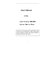
Arm Top Cover
B
A
3
4
5
0
1
2
3
4
5
0
1
2
Rev. no.
09
358487-001
Mar./2005
Service Manual
Arm Top Cover
Removal:
1. Place bobbin winder in the “OFF” position.
2. Remove two arm top cover screws (A) and (B).
3. Remove the arm top cover by pulling it straight upwards.
Replacement:
1. Replacement is the same as removal in reverse order.
Rev. no.
10
358487-001
Mar./2005
Service Manual
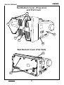
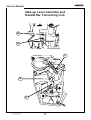
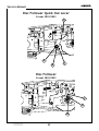
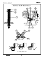
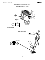
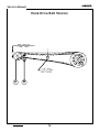
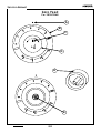
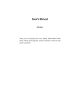
Bed Bottom Cover (Free Arm)
and End Cover
D
C
C
A
F
E
B
Bed Bottom Cover (Flat Bed)
H
G
Rev. no.
11
358487-001
Mar./2005
Service Manual
End Cover
Removal:
1. Remove arm top cover.
2. Remove screw (A).
3. Hold the bottom side of cover (B) and pull it out and up from machine.
Replacement:
1. Replacement of this cover is the same as described above, but in a reverse order.
Bed Bottom Cover (Free Arm)
Removal:
1.
2.
3.
4.
Remove
Remove
Remove
Remove
the bed bottom rubber feet (C).
the screws (D).
8mm hex nut (E).
bed bottom cover (F).
Replacement:
1. Replacement of this bed bottom cover is the same as described above, but in a
reverse order.
Bed Bottom Cover (Flat Bed)
Removal:
1. Remove the four screws (G).
2. Remove bed bottom cover (H).
Replacement:
1. Replacement of this bed bottom cover is the same as described above, but in a
reverse order.
Rev. no.
12
358487-001
Mar./2005
Service Manual
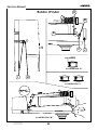
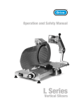
Needle Bar
A
C
B
D
E
Rev. no.
13
358487-001
Mar./2005
Service Manual
Needle Bar
Removal:
1. Remove the face plate and arm top cover.
2. Remove needle by loosing the screw (B). Turn handwheel to bring the needle bar to its
position. Loose screw (A) together with the thread guide and then, remove the entire
needle clamp body. Remove also the needle bar gib (C).
3. Loosen needle bar connecting stud screw (D).
4. Draw needle bar (E) up and out of the machine.
Replacement:
1. Replacement the needle bar the same way as described above, but in a reverse order.
2- Adjust needle bar height (see pages 62-63).
Rev. no.
14
358487-001
Mar./2005
Service Manual
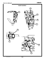
Head End Assembly
A
J
H
I
G
F
B
D
E
Rev. no.
C
15
358487-001
Mar./2005
Service Manual
Head End Assembly
Removal:
123456-
Remove face plate, arm top cover and needle.
Loosen needle bar driving screw (A).
Remove presser foot (D) and presser foot screw (E).
Remove light socket mounting screw (H), light socket (G) and light shield (I).
Remove three head end mounting screws and washers (C), (F) and (J) .
Remove head end assembly (B).
Replacement:
1- Replacement is the same as removal in reverse order.
2- Adjust needle location in the needle plate slot and needle to hook relationship. (See
pages 70-71)
3- Check hook timing (See pages 80-81)and needle bar height (See pages 62-63) and adjust
if necessary.
4- Adjust presser bar alignment and height. (See pages 76-77)
Rev. no.
16
358487-001
Mar./2005
Service Manual
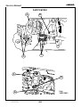
Take-up Lever Assembly and
Needle Bar Connecting Link
B
A
C
D
E
Rev. no.
17
358487-001
Mar./2005
Service Manual
Take-up Lever Assembly and
Needle Bar Connecting Link
Removal:
1- Remove the face plate cover and arm top cover.
2- Turn hand wheel sufficiently to appear the screw (A). Loosen it. Turn again to
appear the screw (B). Loosen it also.
3- Slide take-up lever assembly (C), take-up stud (D) and needle bar connecting link (E).
Replacement:
1- Replacement is the same as removal in reverse order. Make sure that stud (D) is
firmly located against link (E).
2- Adjust needle location in the needle plate slot (See pages 68-69) and needle to
hook relationship (See pages 70-71).
3- Check hook timing (See pages 80-81), needle bar height (See pages 62-63) and
adjust if necessary.
4- Adjust presser bar alignment and height. (See pages 76-77)
Rev. no.
18
358487-001
Mar./2005
Service Manual
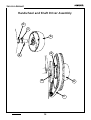
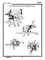
Handwheel and Shaft Driver Assembly
D
C
A
G
B
H
E
F
Rev. no.
19
358487-001
Mar./2005
Service Manual
Hand Wheel and Shaft Driver Assembly
Removal:
1. Remove arm top cover and right side cover.
2. Remove the hand wheel (A) by pulling it out from machine.
3. Remove the shaft pin (B).
4. Remove retaining ring (C) and washer (D) from shaft.
5. Remove the hand wheel pulley (E), the timing belt (F), the spring (G) and the hand
wheel connecting bracket (H).
Replacement:
1. Replacement of the hand wheel is the same as described above, but in a reverse
order.
Rev. no.
20
358487-001
Mar./2005
Service Manual
Cam Stack
For
2809/2859
2818/2868
A
B
Only
2808/2858
D
I
I
E
F
J
H
Rev. no.
Only
2802/2852
G
21
358487-001
Mar./2005
Service Manual
Cam Stack
Removal:
1. Remove arm top cover.
2. Remove three cam stack mounting plate screws (A).
3. Set stitch length and buttonhole dial to "5".
4. Remove cam stack assembly.
Replacement:
1. Replacement is the same as removal in reverse order.
2. Adjust cam stack radial play and pendulum timing (see pages 56-57).
3. Check left-to-right needle location and bight stops (see pages 68-69 and 72-75), adjust if
necessary.
4. Check needle follower clearance (see pages 58-59)
Removal:
Only 2802/2852
1. Remove face plate, arm top cover and end cover.
2. Remove handwheel. (See pages 19-20)
3. Remove head end assembly. (See pages 15-16)
4. Remove take-up lever assembly and needle bar connecting link. (See pages 17 -18)
5. Remove screws (J) and arm shaft bushing (I).
6. Remove nuts (E) and washer (F).
7. Remove needle bar driving arm slide bracket (G).
8. Remove screw (H) of the zig-zag cam (I).
Replacement:
1. Replacement is the same as removal in reverse order.
Rev. no.
22
358487-001
Mar./2005
Service Manual
Disc Follower Quick Out Lever
Except 2802/2852
A
B
D
C
Disc Follower
Except 2802/2852
C
A
B
Rev. no.
23
358487-001
Mar./2005
Service Manual
Disc Follower Quick Out Lever
Except 2802/2852
Removal:
1. Remove arm top cover and the stitch width bracket assembly.
2. Remove screw (A) and eccentric bushing (B).
3. Remove lever (D) and spring (C).
Replacement:
1. Replace these parts the same way as described above, but in a reverse order.
Disc Follower
Except 2802/2852
Removal:
1. Remove arm top cover.
2. Remove retaining ring (A) and spring (B).
3. Pull the follower (C) up to remove it.
Replacement:
1. Replace these parts the same way as described above, but in a reverse order.
Rev. no.
24
358487-001
Mar./2005
Service Manual
Arm Shaft and Horizontal Bevel Gear
F
C
A
B
For 2818/2868
E
I
H
G
J
Rev. no.
25
358487-001
Mar./2005
Service Manual
Arm Shaft and Horizontal Bevel Gear
Removal:
1.
2.
3.
4.
5.
6-
Remove face plate, arm top cover and end cover.
Remove handwheel. (See pages 19 and 20)
Remove head end assembly (See pages 15 and 16)
Remove take-up lever assembly and needle bar connecting link. (See pages 17 and 18)
Remove screws (J) and arm shaft bushing (I).
Loosen the arm shaft collar set screw (F) so that the collar can move along the arm
shaft.
7- Remove set screw (B) in bevel gear (A) releasing it from the horizontal arm shaft.
8- Draw the crank (H) with arm shaft (C) to the left until it clears bevel gear (A).
9- Remove bevel gear (A).
10- Continue to draw arm shaft (C ) out of the machine until it clears collar (E).
11- Remove collar (E).
12- Remove arm shaft (C). The washer (G) will remain on the arm shaft.
Replacement:
1- Replacement is the same as removal in reverse order. (Refer to "bevel gear mesh and
arm shaft end play" on page 54-55)
2- In order to maintain feed timing align the timing mark on the vertical shaft bevel gear
between the two timing marks on the horizontal bevel gear. (Refer to "bevel gear mesh
and arm shaft end play" on page 54-55)
3- Adjust bevel gear mesh and arm shaft end play (See pages 54-55), camstack radial play
(See pages 56-57), and make corrections you believe it's necessary to firmly place the
take-up lever assembly and needle bar connecting link. (See pages 58-59)
4- Check and adjust if necessary:
l
Needle bar height (pages 76-77)
l
Left-center-right needle position (pages 68-69)
l
Zig-zag bight stops positioning (pages 66-67)
l
Needle bar height (pages 76-77)
l
Hook timing (pages 80-81)
Rev. no.
26
358487-001
Mar./2005
Service Manual
Pattern Selector Assembly
Except 2802/2852
C
A
B
Rev. no.
27
358487-001
Mar./2005
Service Manual
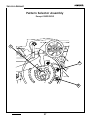
Pattern Selector Assembly
Except 2802/2852
Removal:
1. Remove the free-arm extension table, all the covers, disc stack shaft gear bracket, disc
follower quick out lever and disc follower.
2. Turn the pattern selector dial bringing to sight the screw (A) an then remove this screw.
3. Once again turn the pattern selector dial to bring to sight the screw (B). Remove this
screw too.
5. Remove the pattern selector dial/mechanism (C).
Replacement:
1. Replacement is the same as removal, but in a reverse order.
Rev. no.
28
358487-001
Mar./2005
Service Manual
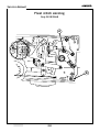
Thread Tension Assembly
C
D
E
F
H
I
K
G
M
J
L
N
B
A
E
Rev. no.
29
358487-001
Mar./2005
Service Manual
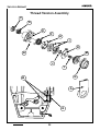
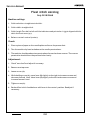
Thread Tension Assembly
Removal:
1. Remove the face plate and arm top cover.
2. Remove the tension mechanism shrouder (A), pulling it forward. Loose de screw (B)
and pull out the tension mechanism assembly.
3. Remove the tension dial (N).
4. Turn adjusting knob insert (M) counterclockwise all the way to release from tension
spindle (L).
5. Remove the tension indicator screw washer (K), the tension spring (J), the tension
spring guide (E), the thread guide (H), the discs ( I ), the tension disc (C), the spring
(D) and the spindle (L).
Replacement:
1. Replace these parts the same way as described above, but in a reverse order taking
into consideration the following:
l The two tension discs ( I ) must be assembled with their convex surfaces facing the
tension disc (C).
l For needle thread tension adjustment see instructions under “Needle Thread Tension”
on pages 86-87.
Rev. no.
30
358487-001
Mar./2005
Service Manual
Motor and Motor Belt
B
D
A
E
I
K
G
Rev. no.
J
31
358487-001
Mar./2005
Service Manual
Motor and Motor Belt
Attention:
Make sure the machine is turned off and remove plug from outlet socket
before disassemblying
Removal:
1. Remove the free arm extension table, bed bottom cover, extension table bottom cover,
arm top cover and right side cover.
2. Loose the two motor adjustment screws (A)
3. Carefully lift the motor and slip the motor belt (D) off the motor pulley (E) and the hand
wheel.
4. Cut off the plastic loop (G)
5. Disconnect wire by pulling the bonding jumper (K) apart.
6. Loosen mounting plate screw (B) 4 or 5 turns only.
7. Remove the screw (.J.).
8. Lift motor and tilt its bottom edge out from the machine until mounting plate ( I ) is clear
of the casting edge.
Replacement:
1. Replacement is the same as removal in reverse order. First pass bonding jumper (K)
through the casting groove. The nut on screw (B) must be properly located in the channel
on the inside of the casting to allow mounting motor
2. Put a new plastic loop to fix wire on the casting.
3. Replace all covers.
Rev. no.
32
358487-001
Mar./2005
Service Manual
Hook
F
E
A
C
K
J
B
I
L
M
N
O
Rev. no.
P
33
358487-001
Mar./2005
Service Manual
Hook
Removal:
1. Remove the free-arm extension table (only 2802, 2808, 2809 and 2818 models), all
the covers, needle plate and the bobbin case. For other models (Flat Bed) remove
slide plate too.
2. Remove feed dog screws (F) and feed dog (E).
3. Remove position plate screws ( I ) and (K).
4. Remove position plate (J).
5. Remove lock bushing (B) and spring (C).
6. Draw retaining plate (A) up and out of the machine.
7. Loosen screw (P) in drive pulley (O).
8. Remove hook (L) by driving it up.
9. Remove hook washer (M), pulley (O) and pulley washer (N).
Replacement:
1. Insert washer (M) inside the hook shaft and then, insert hook (L) into the machine
bed bushing.
2. Insert pulley washer (N) and pulley (O) with the hook drive belt attached on to the
hook shaft pulley.
3. Locate pulley set screw (P) on the flat of the hook shaft.
4. While holding hook (L) down with finger pressure, press up lightly on pulley (O) and
tighten screw (P). Check hook (L) for end play. There should be 0,00 mm - 0,05 mm
end play. Check for free rotating.
5. Replace retaining plate (A) with spring (C) lower leg turned down, insert this leg into
the slot of retaining plate pin. With the flat portion of lock bushing (B) turned up,
insert and push it into the pin, till reaching the pin groove.
6. Replace position plate (J), screws (K) and ( I ) and the bobbin case. Adjust clearances
between bobbin case and position plate (J).(See pages 84-85).
7. Replace feed dog (F) and feed dog screws (E). Adjust feed dog centralization and
parallelism (see pages 92-93). Check feed dog throw and adjust if necessary. (See
pages 94-95).
8. Adjust hook timing (See pages 80-81).
9. Check needle to hook relationship and adjust if necessary. (See pages 70-71).
10.Check needle bar height and adjust if necessary. (See pages 62-63).
Rev. no.
34
358487-001
Mar./2005
Service Manual
Feed Lifting Lever Assembly
A
C
D
B
C
F
E
F
D
Rev. no.
C
35
358487-001
Mar./2005
Service Manual
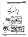
Feed Lifting Lever Assembly
Removal:
1. Set feed regulator dial at number “5” (maximum stitch lenght).
2. Turn handwheel toward the front of the machine to bring the feed dog to its furthest
rear position.
3. Remove the free-arm extension (only 2802, 2808, 2809 and 2818 models) plate and
all the covers.
4. Remove screws (E) to clear the eccentric pin (D) from clamp (F).
5. Remove the spacer (A), the spring (B) and the feed lifting lever assembly (C).
Replacement:
1. Replace these parts the same way as described above, but in a reverse order.
2. Position the eccentric stud (D) making sure spacer (A) is positioned with the hole
offset against the feed lifting lever bushing.
3. Adjust feed dog height related to needle plate surface (see pages 92-93).
4. Be sure spring (B) is properly located in the hole of the casting and inserted over the
nib in the feed lifting lever (C).
Rev. no.
36
358487-001
Mar./2005
Service Manual
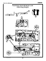
Feed Rock Shaft Assembly
J
B
A
C
M
I
H
N
K
D
E
F
G
L
I
J
H
K
M
N
Rev. no.
37
358487-001
Mar./2005
Service Manual
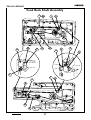
Feed Rock Shaft Assembly
Removal:
1. Remove the free-arm extension table, the thread tension assembly dial, the covers,
the needle plate, the feed dog, the feed lifting lever assembly (N), the hook pulley
(K) and the belt (M).
2. Remove the 10 mm nut (H) and eccentric hinge screw ( I ).
3. Remove rock shaft center clamp screws (F) and (L) and clamps (G) and (A).
4. Remove feed rock shaft assembly (J) together with shaft centers (B) and (E) and with
washers (C) and (D).
Replacement:
1. Replace feed rock shaft assembly (J), shaft centers (B) and (E) together with washer
(C) and (D) and clamps (A) and (G).
2. Tighten clamp the screws (F) and (L).
3. Replace feed lifting lever assembly (N) and then replace the feed dog.
4. Replace eccentric hinge screw ( I ) and hinge screw nut (H). Tighten nut (H) to finger
tightness.
5. Adjust feed dog centralization and feed rock shaft end play. (See pages 92-93).
6. Adjust feed dog height.(See pages 92-93).
7. Adjust feed dog throw.(See pages 94-95).
8. Replace the pulley (K) and the belt (M).
9. Adjust the hook timing (See pages 80-81).
Rev. no.
38
358487-001
Mar./2005
Service Manual
Feed Forked Connection
D
C
D
B
A
A
Only
2818/2868
E
H
Rev. no.
Only
2802/2852
2808/2858
2809/2859
39
I
358487-001
Mar./2005
Service Manual
Feed Forked Connection
Removal:
1. Remove the free arm extension table, bed bottom cover, extension table bottom cover,
arm top cover, right side cover and the hand wheel (see pages 19-20).
2. Remove screw nut ( I ) and the eccentric screw (H).
3. Position the top of the eccentric gear(C) at the back of the machine
4. Turn shaft (E) counterclockwise until stitch regulator stroke (B) is in the vertical position
and keep it in that position
5. Remove the spring (A) and fork (B) by pushing it down
Replacement:
1. Replacement is the same as removal in reverse order.
2. Adjust feed dog throw.(See pages 94-95)
Rev. no.
40
358487-001
Mar./2005
Service Manual
Vertical Shaft Bevel Gear
D
A
A
E
B
C
H
F
F
L
A
D
G
ILLUSTRATION “M”
Rev. no.
41
358487-001
Mar./2005
Service Manual
Vertical Shaft Bevel Gear
Removal:
1.
Remove the free arm extension table, all covers, the front head end assembly, the
buttonhole assembly, the take-up lever assembly, cam stack and hand wheel.
2.
Loosen set screw (E) sufficently to clear vertical shaft bevel gear
(A).
3.
Rotate vertical shaft (C) until vertical gear set screw (B) is accessible.
4.
Loosen set screw (B) to remove gear (A).
Replacement:
1.
Replacement is the same as removal in reverse order.
2.
Check for vertical shaft end play and adjust if necessary. (See pages 52-53)
3.
Locate gear (A) so the top of the gear hub is even with the top of the vertical shaft (C).
4.
Locate arm shaft bevel gear (D) on the arm shaft. (See also "Bevel gear mesh and arm
shaft end play" on pages 54-55)
5.
Position arm shaft bevel gear (A) and (D) so that the mark (G) on the gear (D) straddles
the marks (F) on the gear (A).
6.
Lightly move bevel gear (D) to the left until it just touches vertical shaft gear (A).
Position reference hole (H) upwards. Position shaft gear screw (E) aligned with this
hole.
7.
Tighten bevel gear set screw (E).
8.
Rotate the arm shaft (L) slowly several times. Observe the position of the two gears
with relation to each other. The top edges of the gears should be even with each other
(illustration M). If this condition does not exist, it will be necessary to repeat the above
procedure and move the vertical bevel gear (A) up or down in order to achieve the
correct position.
9.
Adjust take-up lever and needle bar connecting link lost motion (See pages 58-59),
pendulum timing (See pages 64-63), needle location left-to-right (See pages 68-69)
and needle to hook relationship. (See pages 70-71).
10. Check and adjust, if necessary:
l
needle bar height. (pages 62-63)
l
left-center-right needle position. (pages 68-69)
l
zig-zag lever bight stops (pages 72-73)
l
presser bar height (pages 76-77)
l
hook timing (pages 80-81)
Rev. no.
42
358487-001
Mar./2005
Service Manual
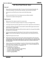
Vertical Shaft
A
B
A
E
F
D
C
Rev. no.
43
358487-001
Mar./2005
Service Manual
Vertical Shaft
Removal:
1. Remove the free arm extension table, all covers, the head end assembly, the buttonhole
assembly, the take-up lever assembly, camstack, hand wheel, horizontal shaft and
vertical shaft bevel gear.
2. Loosen the screws (A) of the belt drive pulley (B) sufficiently to remove it.
3. Loosen the screws (C) and (D) sufficiently to remove the vertical shaft
4. Draw vertical shaft (F) up out of machine with plastic washer and the felt, removing also
feed cam (E) with the washer.
Replacement:
1. Replacement is the same as removal in reverse order.
2. When replacing feed lifting cam (E) find the screw (D) nearer to the groove in the cam
hub on the flat of vertical shaft (F).
3. Refer to "Vertical shaft bevel gear" on pages 41-42 and "Vertical shaft end play" on pages
52-53 for gear setting procedure.
4. Check feed dog height and adjust if necessary.(See pages 92-93)
Rev. no.
44
358487-001
Mar./2005
Service Manual
Stitch Length Control Assembly
Except 2818/2868
C
D
C
A
B
Stitch Length Control Assembly
For 2818/2868
C
D
A
3
4
5
E
B
0
1
2
C
G
F
E
D
Rev. no.
45
358487-001
Mar./2005
Service Manual
Stitch Length Control Assembly
Except 2818/2868
Removal:
1. Remove the free-arm extension table and all the covers.
2. Set feed regulator dial (A) to “5” and remove reverse button (B) and dial (A) pulling
them out.
3. Remove two screws (C) and take out stitch lenght control (D).
Adjustment:
- Set feed regulator dial (A) for maximum stitch length and push on reverse button (B)
and release to check if it returns freely.
Stitch Length Control Assembly
For 2818/2868
Removal:
1. Remove arm top cover.
2. Set stitch length and buttonhole control dial to "buttonhole step 1".
3. Remove retaining rings (A) and (B)
4. By means of a broad bladed screw driver press the pin (D) forward from inside of the
machine.
5. While pressing stud (D), rotate the entire assembly clockwise until the heads of the studs
(C), (D) and (E) are clear of the holes in plate (G).
6. Tilt the bottom of the assembly away from the machine and draw the assembly downward
to remove.
Replacement:
1. Set the stitch length and buttonhole dial at maximum stitch length.
2. Insert the assembly in the machine aligning the head to stud (D) with the large hole (F) in
plate (G). If properly aligned, the assembly should be seating flush against the machine
casting.
3. Slightly depress stud (D) toward the front of the machine and press firmly while rotating
the assembly slightly counterclockwise until the heads of studs (C), (D) and (E) snap into
the openings of the plate (G).
4. Replace retaining rings (A) and (B) and the cam controled feed mechanism.
5. Check and adjust if necessary:
l Needle location in the needle plate slot (Pages 68-69)
l Zero feed (Pages 100-103)
l Buttonhole cutting space (Pages 111-112)
Rev. no.
46
358487-001
Mar./2005
Service Manual
Pattern selector mechanism
Except 2802/2852
B
T
R
J
M
N
J
U
V
D
K
Z
I
E
F
G
X
L
Rev. no.
N
47
358487-001
Mar./2005
Service Manual
Pattern selector mechanism
Except 2802/2852
Removal:
1. Remove arm top cover.
2. Place the handle (B) in the vertical position and pull it up out of the camstack (T).
3. Remove the screws (G) and the camstack gear assembly..
4. Remove pattern selector dial retaining ring (plastic)(D).
5. Remove spring (E) together with the disc follower (F)
6. Remove screws (Y) that hold the levers (H) and ( I ) together
7. Remove the screws (J) and then the stitch lenght lever assembly
8. Remove the screw (U), the washer (V), the lever (K) and the spring (X)
9. Remove the retaining ring (R).out of the needle bar driving arm slide block (M)
10. Remove the retaining ring (L) out of pattern selector dial (N).
11. Remove needle bar driving arm slide block (M) together with the pattern selector dial
(N).
Replacement:
1. Replacement is the same as removal in reverse order.
2. Check and adjust if necessary:
The height of the follower(F) as described: Place the pattern selector in “A” position
and the zig-zag lever in the right position (maximum).Adjust the follower (F) height ,
centralizing its tip with the cam stack track by turning right or left the screw and the
nut (Z).
l Disc and disc follower clearance. (Pages 56-57)
l Cam stack radial play (Pages 56-57)
l Needle bar pendulum timing. (Pages 64-65)
l Buttonhole cutting space. (Pages 111-112)
l Needle location left-to-right (Pages 68-69)
l Zig-zag bight stop positioning (Pages 72-73)
l
Rev. no.
48
358487-001
Mar./2005
Service Manual
Needle position selector lever
For 2818/2868
O
S
P
Q
Rev. no.
49
358487-001
Mar./2005
Service Manual
Needle position selector lever
Removal:
For 2818/2868
1. Remove arm top cover.
2. Remove retaining ring (S), the cam controlled feed follower (O) and the retaining ring
located under it.
3. Remove link screw (P) through the pattern selector dial hole.
4. Remove needle position selection lever assembly (Q).
Replacement:
1. Replacement is the same as removal but in reverse order.
2. Check and adjust if necessary:
l
Left-center-right needle position. (Pages 68-69)
l
Disc and disc follower clearance. (Pages 56-57)
l
Cam stack radial play (Pages 56-57)
l
Needle bar pendulum timing. (Pages 64-65)
l
Buttonhole cutting space. (Pages 111-112)
l
Zig-zag bight stop positioning (Pages 72-73)
Rev. no.
50
358487-001
Mar./2005
Service Manual
Section 2
Sequential Order of
Adjustment Procedures
Rev. no.
51
358487-001
Mar./2005
Service Manual
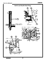
Vertical Shaft End Play
E
B
A
C
0,000mm - 0,025mm
.000” - .001”
H
G
D
A
H
F
F
Rev. no.
52
358487-001
Mar./2005
Service Manual
Vertical Shaft End Play
The vertical shaft must be set to have 0.000 mm - 0.025 mm (.000” - .001”) end play before
setting the arm shaft bevel gear and vertical shaft gear mesh. If incorrectly set, noise may
be generated.
Check:
1. Remove the free-arm extension table, bed bottom cover, extension table bottom cover,
arm top cover and right side cover.
2. Push belt drive pulley (G) up and down to check any existing excessive play.
Adjustment:
1. Loosen the two screws (H) in the belt drive pulley (G) sufficiently to clear the recess in
the vertical shaft (A) and remove pulley (G) .
2. Loosen the two set screws (F) in feed cam (D) approximately one turn.
3. While pulling down on vertical shaft (A) push up on the feed cam (D).
4. Tighten feed cam screws (F).
5. Recheck for vertical shaft end play and make sure the shaft rotates freely without binds.
6. Replace belt drive pulley (G) being sure it is properly seated up against feed cam (D).
7. Adjust arm shaft end play and make the gear (B) of the arm shaft match the gear (E) of
the vertical shaft by tightening screw (C). (See pages 52-53).
8. Adjust hook timing. (See pages 80-81).
Rev. no.
53
358487-001
Mar./2005
Service Manual
Bevel Gear Mesh
and Arm Shaft End Play
A
B
C
D
G
I
H
F
Rev. no.
54
358487-001
Mar./2005
Service Manual
Bevel Gear Mesh
and Arm Shaft End Play
The arm shaft should not have any perceptible shake or end play when assembled in the
machine and should rotate freely without binds.
Check:
1. Remove bed bottom cover, extension table bottom cover,
arm top cover and right side cover.
2. Check for arm shaft end play by pushing the hand wheel left to right and adjust if
necessary.
Adjustment:
1. Loosen set screw (G) in arm shaft collar (F).
2. Push arm shaft (C) to the left by means of the hand wheel.
3. Through the access hole in the front of the casting insert a 0,23 mm (.009") shim gauge
between the plastic washer (H) and the needle bar crank ( I ).
4. While maintaining the position of the shim gauge, pull the arm shaft (C) to the right by
means of the hand wheel.
5. Loosen the screw (B) on the bevel gear (A) and lightly move bevel gear (A) to the left until
it just touches vertical shaft gear (D).
6. Tighten screw (B).
7. Remove the shim gauge and lightly move the arm shaft (C) to the right.
8. While maintaining the position of the arm shaft to the right, bring collar (F) to the left
until they just touch the bushing in the casting.
9. Tighten then the collar set screw (G) making sure one of them is located on the flat of
arm shaft (C).
Rev. no.
55
358487-001
Mar./2005
Service Manual
Disc and Disc Follower Clearance
Except 2802/2852
0,2mm - 0,3mm
.007” - .011”
J
G
H
I
F
Cam Stack Radial Play
Except 2802/2852
E
D
C
Rev. no.
56
358487-001
Mar./2005
Service Manual
Disc and Disc Follower Clearance
Except 2802/2852
The disc follower should be adjusted so that 0,2 - 0,3 mm (.007" - .011") play is obtained
between its contact point and the top of the disc tooth.
Check:
1. Remove arm top cover.
2. Set the zig-zag lever to its maximum width.
3. Set the pattern selector dial (F) between "A" and "B". In this position the "leg" of the
isolating lever (G) will be placed on the top of the selector dial tooth.
4. There should be then a 0,2 - 0,3 mm. (.007" - .011") play between the disc follower
contact point and the top of the disc tooth.
Adjustment:
1. Set the zig-zag lever to its maximum width.
2. Rotate the hand wheel until you meet the disc follower contact point on top of the disc
tooth.
3. Set the pattern selector dial (F) between "A" and "B". In this position the "leg"of disc
follower disengaging lever (G) will be placed on top of the pattern selector dial tooth.
4. Loosen the screw (H).
5. Turn eccentric washer ( I ) so that the frontal point of disc follower disengaging lever (G)
touches the arm slide block (.J.).
6. Tighten screw (H).
7. Recheck the play and adjust once again if necessary.
Cam Stack Radial Play
Except 2802/2852
For the cam stack to perform reliably, there should be a minimum of radial play consistent
with uniform operating tone.
Check:
1. Remove arm top cover.
2. Set machine for straight stitch.
3. Rotate the cam stack (C) back and forth. Rotate hand wheel for one complete turn of the
cam stack. Check for rotational play at four equidistant points (each 90º aproximately)
on a full revolution of the cam stack. If there is one point without rotational play in a
complete revolution of the cam stack, no adjustment is needed even though radial play
may exist in other positions.
Adjustment:
1. Loosen the three cam stack mounting plate screws (D).
2. Move cam stack gear assembly (E) toward the worm gear of the arm shaft to eliminate
rotational play and away from the worm gear of arm shaft to eliminate binding.
3. Tighten the three mounting screws (D).
4. Recheck for rotational play and readjust if necessary.
Rev. no.
57
358487-001
Mar./2005
Service Manual
Take-up Lever and
Needle Bar Connecting Link Lost Motion
B
C
A
Rev. no.
58
358487-001
Mar./2005
Service Manual
Take-up Lever and
Needle Bar Connecting Link Lost Motion
Looseness in either or the take-up lever and needle bar connecting link will cause the
machine to run noisy and may cause irregular stitching.
Check:
1. Remove needle and presser foot.
2. Run machine at high speed and check for rapping noise in head end.
3. Turn hand wheel toward the front of the machine to bring the needle bar to its lowest
position.
4. Grasp the needle clamp and check for excessive vertical and radial play by moving needle
bar up and down rotatively.
Adjustment:
1. Remove face plate cover and arm top cover
2. Loosen thread take-up screw (A).
3. Firmly press thread take-up stud (B) against needle bar connecting link (C) and tighten
screw (A).
4. Turn the hand wheel through several revolutions and check for binds at several different
positions. Readjust if necessary.
5. Recheck for noise and vertical or radial play of the needle bar. If excessive play still
exists, the thread take-up lever and/or the needle bar connecting link is worn and must
be replaced. (See pages 13-14)
Rev. no.
59
358487-001
Mar./2005
Service Manual
Needle Bar Bearings
A
A
C
B
D
F
E
Rev. no.
60
358487-001
Mar./2005
Service Manual
Needle Bar Bearings
Looseness of the needle bar bearings will cause irregular stitching and may cause needle
breakage.
Check:
1. Turn hand wheel toward front of the machine to bring needle bar to its lowest position.
2. Grasp needle clamp (C) and check for excessive front-to-back play.
3. Place needle bar in right needle position.
4. Push needle clamp fully to the left and check for binding by slowly releasing the needle
bar. It should move smoothly to the right.
5. There must be no excessive play or binding in the needle bar bearings.
Adjustment:
1. Remove the face plate.
2. Loosen screw (D).
3. Press up on collar (E) by means of a small screwdriver with just sufficient pressure to
eliminate play in ball bushing (F), yet not bind bushing in its housings.
4. Tighten screw (D).
5. Recheck front to back play of needle bar as described in "Checking items 1 and 2" above.
If excessive play persists replace spring in upper bushing assembly.
Rev. no.
61
358487-001
Mar./2005
Service Manual
Needle Bar Height
A
B
F
C
D
0,40mm - 0,80mm
E
Rev. no.
62
358487-001
Mar./2005
Service Manual
Needle Bar Height
Three rings are cut into the upper end of the needle bar. The distance between the center
and lower ring represents the rise required to form a thread loop at the eye of the needle
required for hook point seizure.
Check:
1.
Remove face plate, presser foot, needle, needle plate and bobbin
case.
2.
Insert a size 18 needle in the needle bar.
3.
Set machine for straight stitch, center needle position.
4.
Turn the hand wheel toward the front of the machine to bring the needle bar to its
lowest position.
5.
Observe the position of the center timing mark (A) with relation to the bottom face of
the upper needle bushing.
6.
Turn the hand wheel toward the front of the machine to bring the lower timing mark (B)
to the same relative position as previously occupied by the center needle bar timing
mark (A). In this position the point of the hook (D) should be within the width of the
blade of the needle. Adjust hook timing, if necessary, to satisfy this requirement. (See
pages 82-83)
7.
Select zigzag, maximum width. Turn the hand wheel toward the front of the machine to
move the hook point to the rear of the needle when the needle is in the left zigzag
position. The top of the needle eye (E) should be 0,40 mm - 0,80 mm (1/64" - 1/32")
below the underside of the hook point.
Adjustment:
1.
Loosen needle bar clamping screw (F) and raise or lower the needle bar to suit the left
needle position requirements.
2.
Tighten screw (F) to pinch tightness.
3.
Needle clamp hub (C) should be parallel with the front edge of the needle plate.
4.
Securely tighten screw (F). Adjust the automatic needle threader bight stop in order not
allow it touches the guide arm of threader shaft.
Rev. no.
63
358487-001
Mar./2005
Service Manual
Needle Bar Pendulum Timing
Except 2802/2852
5,5 mm - 7,5 mm
.220” - .300”
A
C
D
E
B
Rev. no.
64
358487-001
Mar./2005
Service Manual
Needle Bar Pendulum Timing
Except 2802/2852
Check:
1. Set the machine for zig-zag, maximum width.
2. Remove the presser foot.
3. With the presser bar in a raised position, hold a piece of paper in place over the needle
plate, so needle penetration may be observed.
4. Turn hand wheel toward the front of the machine.
5. As the needle is rising from the right perforation, the point of the needle should be
moving to the left lightly touching the edge of the paper without enlarging the hole and
should reach its peak of ascent slightly past center of the two extreme positions of the
needle. (illustration A).
6. On the downward stroke, all lateral movement should cease when the needle point is 5,5
mm - 7,5.mm (.220" - .300") above the needle plate. The needle must return into the
opposite hole precisely.
Adjustment:
1. Remove arm top cover.
2. Rotate hand wheel toward the front of the machine to bring reference mark (C) on the
cam stack opposite the follower (B) bring the needle to its lowest position in the left
hand swing of zig-zag.
3. Loosen two cam stack clamping screws (D).
4. Advance pendulum timing if needle begins its right to left movement too late by rotating
cam stack (E) slightly to the right (clockwise). Retard pendulum timing if needle begings
its right-to-left movement too soon by rotating camstack (E) slightly to the left
(counterclockwise).
5. Tighten one clamping screw (D) and recheck pendulum timing. Readjust if necessary.
6. If pendulum timing is correct, tighten both clamping screws (D) securely.
Rev. no.
65
358487-001
Mar./2005
Service Manual
Zigzag Centralizing Procedure
=
A
=
ILLUSTRATION F
B
For 2802/2852
D
C
Rev. no.
66
358487-001
Mar./2005
Service Manual
Zigzag Centralizing Procedure
Check:
1.
2.
3.
4.
Set the machine for zig-zag, maximum width.
Remove the presser foot.
Rotate hand wheel to make the needle penetrate the needle plate slot left-to-right.
As the needle penetrates the slot left-to-right an equal lateral clearance between
needle and needle plate slot, according to illustration "F".
Adjustment:
1. Remove face plate cover and arm top cover
2. Set stitch width lever to maximum zig-zag.
3. Rotate the hand wheel toward the front of the machine, until the needle in its
descending way, reaches the needle plate level.
4. Loosen screw (A).
5. Move needle bar (B) to right or left reducing or increasing the lateral clearance as
necessary, see illustration "F".
6. Without disturbing the position of the needle bar (B), tighten screw (A).
7. Recheck and readjust if necessary.
For 2802/2852
Check:
1.
2.
3.
4.
Set the machine for zig-zag, maximum width.
Remove the presser foot.
Rotate hand wheel to make the needle penetrate the needle plate slot left-to-right.
As the needle panetrates the slot left-to-right an equal lateral clearance between
needle and needle plate slot, according to illustration "F".
Adjustment:
1.
2.
4.
5.
Remove face plate cover and arm top cover
Set stitch width lever to maximum zig-zag.
Loosen screw (C).
Move zigzag cam (D) to right or left reducing or increasing the lateral clearance as
necessary, see illustration "F".
6. Tighten screw (C).
7. Recheck and readjust if necessary.
Rev. no.
67
358487-001
Mar./2005
Service Manual
Needle Location in the
Needle Plate Slot
B
A
NEEDLE SIZE 14
=
=
ILLUSTRATION “A”
A
Only 2802/2852
NEEDLE SIZE 14
=
=
ILLUSTRATION “B”
Rev. no.
B
68
358487-001
Mar./2005
Service Manual
Needle Location in the
Needle Plate Slot
When a size 14 needle penetrates the needle plate slot, it must remain in the center of that
opening.
Adjustment:
1. Remove arm top cover.
2. Rotate hand wheel toward the front of the machine until a needle size14 penetrates the
needle plate slot (See illustration "A").
3. Loosen screw (A).
4. Move slide block bracket (B) to right or left until the needle is located in the center of
needle plate slot in a position corresponding to 5/6 o'clock on a watch, and with a 0,18
mm (.007") clearance between the needle and the needle plate slot edge, as shown in
the illustration "A".
5. Tighten screw (A).
Only 2802/2852
When a needle size 14 penetrates the needle plate slot it must remain approximately in
the center of that opening.
Adjustment:
1. Remove the arm top cover, face plate and presser foot.
2. Set stitch width lever to straight stitch position.
3. Rotate handwheel toward the front of the machine until a needle size 14 penetrates
the needle plate slot (see illustration “B”).
4. Loose screw (A).
5. Centralize the needle in the center slot, tighten screw (A).
6. Check and readjust if necessary.
Rev. no.
69
358487-001
Mar./2005
Service Manual
Needle to Hook Relationship
0,00 mm INTERFERENCE
.000” INTERFERENCE
0,10 mm CLEARANCE
.004” CLEARANCE
ILLUSTRATION “A"
A
C
B
D
Rev. no.
70
358487-001
Mar./2005
Service Manual
Needle to Hook Relationship
Proper needle to hook relationship is required to prevent skipping of stitches on various
fabrics and to prevent hook and needle damage.
If the needle is too far from the hook, the hook point will be unable to pick up the needle
thread loop and skipping of stitches will occur. If the needle is too close to the hook, the
hook point will strike the needle as it passes and may cause damage to the hook point or
needle breakage.
Before attemptinq any adjustment, needle location and hook timing must be verified. Also,
visually inspect the hook point for any damage. If the point is bent or burred, it must be
replaced.
Check:
1. Set the machine for straight stitch, center needle position.
2. Remove presser foot, needle plate and bobbin case.
3. Install a size 18 needle.
4. Turn the hand wheel toward the front of the machine until the point of the hook is
directly behind the needle. There should be a 0,00 mm (.000") interference to a 0,10 mm
(.004") clearance between the point of the hook and the needle (illustration A).
Adjustment:
1. Remove needle plate, bobbin case, face plate cover, arm top cover, light, light socket
and light shield.
2. Loosen screws (A), (B) and (C).
3. Pivot the head end assembly (D) on screw (A) front to back to obtain the proper distance
between the needle and the hook point. (illustration A).
4. Securely tighten screws (A), (B) and (C).
Rev. no.
71
358487-001
Mar./2005
Service Manual
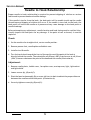
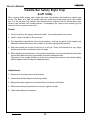
Maximum Width Zigzag Lever
Bight Stop
Except 2808/2858
A
B
A
B
Only
2802/2852
Rev. no.
72
358487-001
Mar./2005
Service Manual
Maximum Width Zigzag Lever
Bight Stop
Except 2808/2858
Check:
1. Set the machine for zigzag.
2. Rotate handwheel to make needle penetrate on both left and right sides of a paper;
than measure the distance between the holes are to be 5,6 to 6,0 mm.
3. If the distance it is wrong, adjust.
Adjustment:
1. Remove the arm top cover.
2. Loose stop screw (A).
3. Rotate bracket stop (B) clockwise to increase the width or counterclockwise to
decrease the width.
4. Tighten bracket stop set screw (A).
5. Recheck and readjust if necessary.
Rev. no.
73
358487-001
Mar./2005
Service Manual
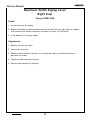
Needle Bar Safety Bight Stop
(Left Side)
B
A
Rev. no.
74
358487-001
Mar./2005
Service Manual
Needle Bar Safety Bight Stop
(Left Side)
When sewing width zigzag, the needle bar must not contact the needle bar safety stop
screw. The point of a size 18 needle must not strike the throat plate when the needle
bar is in its extreme left position but should deflect slightly into the throat plate hole
when in the extreme left needle position. If improperly set, may occurn jamming of the
selector kick out system may occur.
Check:
1. Set the machine for zigzag, maximum width. Set needle position at center.
2. Install a size 18 needle in the machine.
3. Turn handwheel toward the front of the machine, to bring the point of the needle just
above the throat plate when the needle is in the left zigzag needle position.
4. Push the needle bar to the left as far as it will go. There still should be a very slight
displacement of the needle bar, before it stops.
5. While holding the needle bar in its furthest left position, turn the handwheel toward the
front of the machine to bring the needle into the needle plate slot.
The point of the needle should not strike the needle plate surface, but should slightly
deflect against the left edge of needle plate slot.
Adjustment
1. Remove the arm top cover and face plate.
2. Loosen 8mm safety stop screw locking nut (B).
3. Adjust the safety stop set screw (A) to satisfy the above condictions.
4. While maintaining the position of screw (A), tighten nut (B).
5. Check and readjust if necessary.
Rev. no.
75
358487-001
Mar./2005
Service Manual
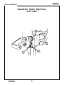
Presser Bar Height and Alignment
C
A
7,35 a 7,60 mm.
B
B
Rev. no.
76
358487-001
Mar./2005
Service Manual
Presser Bar Height and Alignment
Presser bar height and alignment must be correct to insure proper operation of attachments
and provide straight controlled feeding qualities.
Check.
1. Remove needle.
2. Raise presser foot to its heighest position.
3. Presser bar height is correct when the distance between the underside of the presser
foot and the needle plate is 7,35 mm - 7,60 mm (.290" - .300").
Adjustment:
1. Remove needle.
2. Remove face plate, light, light socket and light shield.
3. Turn hand wheel to position feed dog bellow needle plate.
4. Raise presser bar to its highest position.
5. Losen screw (A) and raise or lower presser bar (B) as required to obtain correct height.
6. Tighten screw (A) to pich tightness.
7. Gently lower presser bar on needle tightness.
8. Turn presser bar (B) as necessary to align presser foot sides with the slots in the needle
plate (C).
9. Raise presser bar and securely tighten screw (A).
Rev. no.
77
358487-001
Mar./2005
Service Manual
Hook Drive Belt Tension
8,60 - 10,20 mm
(.338” - .400”)
140 - 144 g
(5.0 - 5.14 oz)
A
Rev. no.
B
78
358487-001
Mar./2005
Service Manual
Hook Drive Belt Tension
Check:
1. The hook drive belt tension should be such that a weight of 140 g (5 oz.) centrally
located between the pulleys, deflects the belt 8,6 mm - 10,2 mm (.338” - .400”).
Adjustment:
1. Remove free arm extension table, bed bottom cover and extension table bottom cover.
2. Loosen screw (A) and slide belt tensioner (B) up or down until correct tension is
achieved.
3. Tighten screw (A).
Rev. no.
79
358487-001
Mar./2005
Service Manual
Hook Timing
(Hook and Needle Synchronism)
A
E
B
C
D
Rev. no.
80
E
E
358487-001
Mar./2005
Service Manual
Hook Timing (Hook and Needle Synchronism)
Before hook timing is attempted, needle location (page 70-71), needle to hook relationship
(page 72-73) and hook drive belt tension (page 80-81) must be correct.
Check:
1. Remove face plate, presser foot, needle, needle plate and bobbin case.
2. Insert a size 18 needle.
3. Set the machine for straight stitch, center needle position.
4. Turn the hand wheel toward the front of the machine to bring the needle bar to its lowest
position.
5. Observe the position of the center timing mark (A) with relation to the upper needle bar
bushing.
6. Turn the hand wheel toward the front of the machine to bring the lower timing mark (B)
to the same relative position as previously occupied by the center needle bar timing
mark. In this position, the point of the hook (C) should be in the center of the needle
blade.
Adjustment:
1. Remove the free arm extension table, bed bottom cover, extension table bottom cover,
needle plate, bobbin case and presser foot.
2. Loosen the two screws (E) in the belt drive pulley (D).
3. Turn the hand wheel toward the front of the machine to bring the lower timing mark (B)
to the position the center needle bar timing mark was previously located (A). In this
position, the point of the hook (C) should be in the center of the needle blade. Turn the
pulley (D) until the hook point is located behind the needle.
4. Press up with finger presser on pulley (D) and tighten the two screws (E).
5. Recheck and readjust if necessary.
6. Check needle bar height.(See pages 62-63).
Rev. no.
81
358487-001
Mar./2005
Service Manual
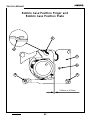
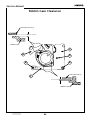
Bobbin Case Position Finger and
Bobbin Case Position Plate
A
A
C
D
E
B
0,25mm
Rev. no.
82
0,36mm
358487-001
Mar./2005
Service Manual
Bobbin Case Position Finger
Check:
1. Position finger (A) must not extend above the left fork of the bobbin case but must
be flush with the surface.
Adjustment:
1. Adjust the finger position as necessary to obtain the correct location or replace the
position bracket (C), if necessary.
Bobbin Case Position Plate
Check:
1. Turn handwheel toward front of machine to bring hook point to position (D) .
2. Locate the bobbin case so that the left side of its fork is resting gently against the
position finger (A).
3. With a feeler gauge, check for a clearance of 0,25 mm - 0,36 mm between the heel
of the bobbin case and position bracket (C).
Adjustment:
1. Remove needle plate.
2. Loose screws (B) and (E).
3. Move position bracket (C) left or right to obtain clearance of 0,25 mm - 0,36 mm
between the heel of the bobbin case and position bracket (C).
4. Tighten screw (B) and (E) being sure the right edge of bracket (C) is parallel with the
edge of the casting (polished corner nearest the portion bracket).
Rev. no.
83
358487-001
Mar./2005
Service Manual
Bobbin Case Clearance
RETAINING PLATE (A)
0,25 - 0,36 mm
BOBBIN CASE
C
A
D
E
B
POSITION PLATE (C)
F
0,25 - 0,36 mm
BOBBIN CASE
Rev. no.
84
358487-001
Mar./2005
Service Manual
Bobbin Case Clearance
Check:
1. Remove needle plate.
2. Turn handwheel toward the front of the machine to bring hook point to position (D).
3. Place the rear of the bobbin case against the bobbin case position plate (C).
4. Use a GM8092 feeler gauge to check if clearance between plate (A) and bobbin case
surface is correct. The smaller side of the feeler gauge should freely pass through, but
the other side should not.
5. Using the same feeler gauge, check for correct clearance between the extension of
positon plate (C).and bobbin case upper surface (F). Procede as in the item 4 above.
Adjustment:
1. Turn hand wheel toward the front of the machine to bring the hook point to position (D).
2. By means of a screwdriver adjust clearance between retaining plate (A) and bobbin case,
bending the plate upwards or downwards according to feeler gauge.
3. With the same screwdriver adjust clearance between the extension of position plate
(C).and bobbin case upper surface ("F" area), bending the extension upwards or
downwards according to feeler gauge.
Rev. no.
85
358487-001
Mar./2005
Service Manual
Needle Thread Tension
B
G
A
C
D
C
F
E
B
A
F
I
H
J
I
Rev. no.
86
358487-001
Mar./2005
Service Manual
Needle Thread Tension
Machine setting:
1. Straight stitch, 2 mm stitch length (12 stitches per inch).
2. Center needle position.
3. Machine threaded for sewing.
Check:
1. The thread take-up spring (C) must be set to come to rest against take-up spring stop (B)
between the time of the needle point penetration and needle eye entrance into 1-ply of
light weight fabric (illustration 1) .
2. Take-up spring (C) must not bind or hang up as it is raised and lowered through its full
travel from stop (B).
Adjustment (to set take-up spring tension)(C):
1. Turn tension dial (A) to furthest left ("9") position.
2. Remove the dial (A) and schrouder (D).
2. Remove tension assembly complete from the machine and disassembly it.Remove clip
(E) from tension body (F) and carefully raise the coiled spring (C) and move the tail (G) to
the next notch in body (F).
3. Move to the left (counterclockwise) to increase tension and to the right (clockwise) to
decrease tension.
4. Reassembly tension assembly complete in the machine. Mount the dial (A) observing the
reference position “9” and schrouder (D).
Adjustment (to set take-up spring stroke)(C):
1. Set machine at straight stitch, center needle position, medium stitch lenght, tension
between "3" and "4".
2. Thread machine for sewing and sew about 5 cm.(2 inches).
3. The take-up spring (C) should come to rest on stop (B) between the time of needle point
penetration and needle eye entrance into 1-ply of light weight fabric (illustration 1).
4. To increase or decrease take-up spring stroke set tension dial (A) to "O", move thread
guide plate (H) away from body (F) and turn plate (H) counter-clockwise to decrease and
clockwise to increase stroke of take-up spring (C).
Adjustment (to set needle thread tension):
1. Lower the presser foot.
2. Turn tension dial (A) to the furthest left ("O") position.
3. Remove the free arm extension table, tension assembly dial, the knobs of the zig-zag
and needle position levers and all covers.
4. Pull tension dial (A) straight out and off the tension assembly,
5. Turn adjusting knob (J) to the right (clockwise) to increase tension and to the left
(counterclockwise) to decrease tension.
6. Set adjusting knob (J) until a barely perceptible drag (5 - 15 grams) can be felt as
thread is gently drawn through the tension discs.
7. Press on tension dial (A) so that the stop in tension knob ( J) is resting against and to the
right of the stop in tension body (F).
8. Finally, reassembly covers and turn dial to the right between numbers 3 and
Rev. no.
87
358487-001
Mar./2005
Service Manual
Bobbin Winder
D
B
A
C
J
1,5 mm
(1/16”)
ILLUSTRATION "K"
I
H
ILLUSTRATION "L"
ILLUSTRATION "M"
Rev. no.
88
358487-001
Mar./2005
Service Manual
Bobbin Winder
Check:
1. Run machine and push bobbin winder spindle (A) to the left (OFF position).
2. Place empty bobbin on bobbin winder spindle (A).
3. Push bobbin winder from side to side in side opening (D). At no time should any part of
the bobbin winder or the bobbin touch either the opening or the bobbin winder stop (C).
4. Check that the spindle (A) turns freely and that there is no vertical (up and down) play. If
either condition exists, the bobbin winder assembly should be replaced.
5. Check that the bobbin winder stays in either the left or right position under spring
pressure. If spring pressure is absent, spring might be weak or broken and will need to be
replaced.
6. Lift up on bobbin winder tension disc (I) and feel for presence of slight tension. If tension
is absent, replace bobbin winder tension assembly.
7. Place bobbin winder to the right (ON) position and run machine, checking for even
rotation of bobbin winder. If the bobbin winder hesitates or fails to rotate, remove
covers and check for worn or absent bobbin winder rubber ring .
8. Thread machine for bobbin winding (illustration M).
9. Wind a bobbin and check if thread is wound evenly, (illustration K), or forms a cone at
either end, (illustration L). The bobbin winder should stop turning when the thread is
wound to 1,5 mm (1/16") from the outer rim of the bobbin.
Adjustment:
1. To correct conical winding of the thread (illustration L), adjust the height of the tension
assembly by turning the adjusting screw (H) clockwise or counterclockwise as necessary.
2. If the bobbin winder stop (C) disengage too soon or fails to operate, loosen screw (B) and
turn stop (C) toward the hand wheel to give more thread on the bobbin or away from the
hand wheel, for less thread, tighten screw (B).
3. Recheck operation of bobbin winder and stop.
Bobbin winder operation and disengagement. Readjust if necessary.
Rev. no.
89
358487-001
Mar./2005
Service Manual
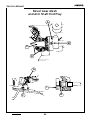
Feed Rock Shaft End Play
C
B
E
F
A
C
Rev. no.
90
358487-001
Mar./2005
Service Manual
Feed Rock Shaft End Play
There must be no end play or binds in feed rock shaft (C).
Check:
1. Remove the free arm extension table, bed bottom cover and extension table bottom
cover.
2. Move feed rock shaft (C) left to right to check for end play.
Adjustment:
1. Hold feed rock shaft (C) to the left against rock shaft center (B) and check that the feed
dog is centralized in the needle plate slots.
2. Loosen left center clamp screw (A) and move center (B) with rock shaft (C) left or right
to centralize feed dog in needle plate slots.
3. Tighten left center clamp screw (A).
4. Loosen the right center clamp screw (F).
5. Move the right rock shaft center (E) to the left against rock shaft (C) and tighten clamp
screw (F).
Rev. no.
91
358487-001
Mar./2005
Service Manual
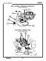
Feed Dog Centralization and
Feed Dog Height
A
1,00mm
.040’’
1,20mm
.047’’
B
D
C
G
F
E
Rev. no.
92
358487-001
Mar./2005
Service Manual
Feed Dog Centralization
Check:
1. Set the machine to straight stitch, maximum stitch length.
2. Turn the handwheel toward the front of the machine to bring feed dog (A) to its
highest point. Check and confirm that the drop-in feed selector lever is displaced to
the right (feed dog at higest position).
3. Feed dog (A) must be parallel to and centrally located in the needle plate (B) slots.
Adjustment:
1. Remove presser foot and needle plate.
2. Loose the two feed dog screws (C) and move feed dog (A) as required to satisfy
proper alignment. Feed dog screws (C) must be located at the very rear of the slots
(D) of feed dog.
3. Tighten feed dog screws (C). Recheck and readjust if necessary.
Check:
Feed Dog Height
1. Set the machine to straight stitch, maximum stitch length.
2. Turn the handwheel toward the front of the machine to bring feed dog (A) to its
highest point at the rear of its stroke.
3. The top of feed dog (A) must be 1,00 mm - 1,20 mm above the top surface of the
needle plate (B).
Adjustment:
1. Remove needle plate, free arm extension table, tubular bed botton cover and bed
botton cover.
2. Loose (not too much) the screws (G).
3. The highest point of hinge stud eccentric (F) must be to the right before making the
adjustment. By means of a 7,0 mm open end wrench, rotate eccentric hinge stud (F)
left or right to raise or lower the feed dog.
4. While pushing up snugly on eccentric (F),tighten screws (G).
Tightening the two hinge stud clamp screws (G) will cause the feed lifting lever (E) to
raise slightly thereby causing the feed dog to be slightly higher than actually set.
There must be no looseness or binding of feed lifting lever (E). Push in on feed lever
(E) and slowly allow it to return to its normal position. There should be no hang-ups
or binds. Move lever up and down to check for looseness.
Rev. no.
93
358487-001
Mar./2005
Service Manual
Feed Dog Throw
0,38mm
.015”
B
Rev. no.
A
0,50mm
.020”
C
94
358487-001
Mar./2005
Service Manual
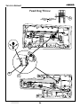
Feed Dog Throw
Check:
1. Set the machine to maximum stitch length.
2. Turn handwheel toward the front of the machine until feed dog (A) is in its most
forward position.
3. There should be a clearance of 0,38 mm - 0,50 mm between the center bar of feed
dog (A) and the edge of the center slot of the needle plate.
Adjusting:
1. Remove the free-arm extension table, arm top cover, face plate and front and rear
covers.
2. Loose nut (C).
3. Turn eccentric screw (B) clockwise or counterclockwise as required to obtain correct
feed dog throw.
4. Tighten nut (C).
Rev. no.
95
358487-001
Mar./2005
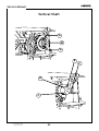
Service Manual
Stitch length regulator spring tension
For 2818/2868
A
C
B
Rev. no.
96
358487-001
Mar./2005
Service Manual
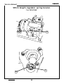
Stitch length regulator spring tension
For 2818/2868
The reverse button must operate smoothly with the stitch length set at maximum stitch.
Adjustment;
1. Remove arm top cover, right side cover, motor belt and hand wheel.
2. Loosen screw (A) in feed regulator assembly.
3. Upon loosening this screw, the stud (C).will rotate, allowing the spring (B) to loosen
tension.
4. Rotate stud (C) one complete counterclockwise revolution only to place proper tension
on spring (B).
5. Tighten screw (A).
Rev. no.
97
358487-001
Mar./2005
Service Manual
Motor Belt Tension
A
Rev. no.
98
358487-001
Mar./2005
Service Manual
Motor Belt Tension
Too tight a motor belt tension can cause the machine to run slow and will overload the
motor. Too loose a motor belt tension will create belt noise and may cause jumping of the
belt teeth on cogged motor pulley.
Adjustment:
1- Remove arm top cover and right side cover.
2- Loosen adjusting screws (A).
3- Bring the motor up or down until the machine is running at its adequate highest speed.
4- Tighten screws (A).
Rev. no.
99
358487-001
Mar./2005
Service Manual
Zero Feed
Except 2818/2868
A
B
0
1
C
2
3
D
4
5
D
E
Rev. no.
100
358487-001
Mar./2005
Service Manual
Zero Feed
Check:
Except 2818/2868
1. Remove needle.
2. Place a 2-plies of light-weight fabric over the needle plate.
3. Set stitch length control dial (B) to "0" (zero).
4. Set reverse button mark (C) in line with reference mark (A) on the front cover.
5. Lower presser foot on fabric and run machine at full speed.
6. There should be no feeding of the fabric.
Note: On occasion, there may be a machine where absolute zero feed is difficult to
achieve. In such cases, forward feed movement must not exceed 6,35 mm in
fifteen seconds. Reverse feed is unacceptable.
Adjustment:
1. Turn stitch length dial (B) to number “5”.
2. Remove reverse button (D) by pulling straight out from machine.
3. Return stitch length dial to "O" (zero).
4. Lower presser foot over the two plies of fabric and run the machine at full speed.
5. Turn adjusting screw (E) clockwise to decrease forward feed and counterclockwise to
decrease reverse feed until there is no feeding of the fabric.
6. Replace the reverse button (D) with its buttonhole mark (C) in line with the reference
mark (A) on the machine front cover.
Rev. no.
101
358487-001
Mar./2005
Service Manual
Zero Feed
For 2818/2868
A
B
C
D
D
E
Rev. no.
102
358487-001
Mar./2005
Service Manual
Zero Feed
For 2818/2868
Check:
1. Remove needle.
2. Place a 2-plies of light-weight fabric over the needle plate.
3. Set stitch length control dial (B) to "O" (zero).
4. Set reverse button with indicator mark (C) in line with reference mark (A) on the cover.
5. Lower presser foot on fabric and run machine at full speed.
6. There should be no feeding of the fabric.
Note: On occasion, there may be a machine where absolute zero feed is difficult to
achieve. In such cases, forward feed movement must not exceed 6,35 mm (.250") in
fifteen seconds. Reverse feed is unacceptable.
7. Turn stitch length dial to number "4" buttonhole position and recheck. There should be
no feeding of the fabric.
Adjustment:
1. Turn stitch length dial to number "5" (maximum stitch length).
2. Remove reverse button (D) by pulling straight out from machine.
3. Return stitch length dial to "O" (zero).
4. Lower presser foot on single ply of fabric and run machine at full speed.
5. Turn adjusting screw (E) clockwise to decrease forward feed and counterclockwise to
decrease reverse feed until there is no feeding of the fabric.
6. Replace reverse button (D) with indicator mark (C) in line with reference mark (A) on
the front of the machine.
Rev. no.
103
358487-001
Mar./2005
Service Manual
Lubrication
O
O
G
O
O
O
O
G
O
Rev. no.
104
358487-001
Mar./2005
Service Manual
Lubrication
G
O
O
G
G
G
Only
2802/2852
G
Rev. no.
105
358487-001
Mar./2005
Service Manual
Lubrication
O
O
O
G
Rev. no.
106
358487-001
Mar./2005
Service Manual
Lubrication
G
G
O
O
O
G
G
O
O
G
O
G
Rev. no.
G
107
358487-001
Mar./2005
Service Manual
Lubrication
In order to meet the customer minimum lubrication requirement, the machine must be
lubricated as indicated on pages 104/105/106/107.
Only Singer oil and Singer grease must be used.
Use of parafin based oil, or non-silicon type grease, will create a build up of residue on the
bearing surfaces. The self-lubricating qualities of the bearings will be defeated by clogging
of the pores in the bearing if such oil or grease are used.
All thread, lint, or any foreign matter must be removed before lubrication.
O = Singer oil
G = White grease for lubrication.
Applying lubrication
l
Applied to cam surfaces, cover entire surface.
l
To gears, cover each tooth.
l
To slides, cover entire surface.
Do not apply grease to oil-impregnated metal parts.
Rev. no.
108
358487-001
Mar./2005
Service Manual
Flexi stitch zeroing
Only 2818/2868
A
B
Rev. no.
109
358487-001
Mar./2005
Service Manual
Flexi stitch zeroing
Only 2818/2868
Machine settings:
1. Stitch selection: straight stretch stitch.
2. Stitch width: straight stitch.
3. Stitch length:Turn dial to left until the indicator mark printed on it ( ) is aligned with the
dot in the front cover ( ).
4. Balance control: neutral (center).
Check:
1. Place a piece of paper on the needle plate and lower the presser foot.
2 . Turn the machine by hand and observe the needle penetrations.
3. The machine should produce two penetrations forward and one reverse. The reverse
penetration should enter the previous hole cleanly.
Adjustment:
1. Check "zero feed" and adjust if necessary.
2. Remove arm top cover.
3. Loosen screw (A).
4. While holding screw (A), move lever (B) slightly to the right to increase reverse and
decrease forward feed. Move lever (B) slightly to the left to decrease reverse and
increase forward feed.
5. Tighten screw (A).
6. Recheck flexi stitch feed balance with lever in the neutral position. Readjust if
necessary.
Rev. no.
110
358487-001
Mar./2005
Service Manual
Buttonhole cutting space
Only 2818/2868
C
B
A
0,50mm - 1,00mm
(.020” - .040”)
0,50mm - 1,00mm
(.020” - .040”)
ILLUSTRATION “D”
Rev. no.
111
358487-001
Mar./2005
Service Manual
Buttonhole cutting space
Only 2818/2868
To allow sufficient space for cutting without damaging the thread, the buttonhole cutting
space must be approximately 0,50 mm - 1,00 mm ( .020" - .040") .
Check:
1. Remove presser foot.
2. Insert a number 9 needle to provide better visibility and accuracy when checking
buttonhole cutting space.
3. Turn buttonhole control dial to number "1" position.
4. While holding a piece of paper over the needle plate, make two needle penetrations.
5. Without disturbing the position of the paper, turn buttonhole control dial to number "3"
position and make two more needle penetrations.
6. The distance between the two inner perforations should be 0,50 mm - 1,00 mm (.022" .040").
Adjustment:
1. Remove arm top cover.
2. Loosen screw (C) while maintaining the position of bracket (B).
3. Move stitch width control lever (A) left to increase space and right to decrease cutting
space.
4. Tighten screw (C).
5. Recheck and readjust if necessary.
Rev. no.
112
358487-001
Mar./2005