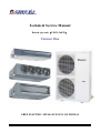
1
[Gree Central Air Conditioner]
Technical Service Manual
Ducted type unit(2.3KW-16KW)
Version One
GREE ELECTRIC APPLIANCES.INC.OF ZHUHAI
-1-
FG Series wind pipe blowing air-conditioning unit
Section One: A series small ducted type unit
Chapter 1 Summary
1.1,
Product Summary
1.2,
Expression method and example for unit model
1.2.1
Model expression method
1.2.2
Example
1.3,
Unit outline drawing and combination example
1.3.1
Outline drawing
1.3.2
Combination example
1.4,
Unit working principle and system drawing
1.5,
Installation space of the unit
1.6,
Technical and specifications of the product
Chapter 2 Electricity and control
2.1
Strong current
2.1.1
Circuit diagram
2.1.2
List of wiring
2.2
Light current
2.2.1
Description and usage method of manual controller
2.2.2
Description and usage method of remote controller
2.4,
Centralized control
2.5
Wiring
2.6
Dial code
Chapter 3 Operation debugging and malfunction diagnosis
3.1
List of unit operation conditions and check items
3.2
List of parameter changes of unit operation
3.3
List of malfunction analysis
3.4
Check list of malfunction code
Chapter 4 Care and Maintenance
4.1
Explosive Views and Spare Parts List
4.2
Parts disassembly procedure
4.3
Maintenance items
-2-
Contents
Section Two: B series small ducted type unit
Chapter 1 Summary
1.1,
Product Summary
1.2,
Expression method and example for unit model
1.2.1
Model expression method
1.2.2
Example
1.3,
Unit outline drawing and combination example
1.2.1
Outline drawing
1.2.2
Combination example
1.4,
Unit working principle and system drawing
1.5,
Installation space of the unit
1.6,
Technical and specifications of the product
Chapter 2 Electricity and control
2.1
Strong current
2.1.1
Circuit diagram
2.1.2
List of wiring
2.2
Light current
2.2.1
Operation mode
2.2.2
Description and usage method for manual controller
Chapter 3 Operation debugging and malfunction diagnosis
3.1
List of unit operation conditions and check items
3.2
List of parameter changes of unit operation
3.3
List of malfunction analysis
3.4
Check list of malfunction code
Chapter 4 Care and Maintenance
4.1
Explosive Views and Spare Parts List
4.2
Parts disassembly procedure
4.3
Case of defective project and maintenance
-3-
FG Series wind pipe blowing air-conditioning unit
Section One A series small ducted type unit
Overview of chapter one
1.1, Product summary
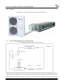
The ducted type unit means that the outdoor unit and the indoor unit are connected by a copper pipe and the
air-supply pipe leads to each room from the indoor. That is why it is called the ducted pipe unit. The detailed
working method is that: the indoor heat exchangers gather in an indoor unit, the cool air produced by the indoor
unit is sent to each room from the system air duct, then is sent back to the indoor unit via the air duct, after it is
cooled and mixed with some fresh air, it is sent out again. This is a central air conditioner with the complete air
system.
Gree’s A series of air conditioner unit with the air supplied by the small air duct combines the advantages of the
central air conditioner which are being comfortable and top-grade and the advantages of the small type of
separated home air conditioner which are being convenient and flexible in installation, etc. It is highly efficient,
energy-saving with a long air supply distance and good indoor air quality. It is reliable in operation and convenient
in usage and is widely applied to various small supermarkets, chain stores, families with multiple living rooms,
hotels, restaurants, offices, meeting rooms and villa families.
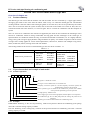
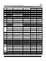
The existing models of the A series of small ducted type units are shown in Table 1.1-1.
Table 1.1-1
Cooling only
Item
Multi-excess pressure unit
Common excess pressure unit
FG2.6H/A
FG5H/A
FG7.5H/A
FG10H/A
FG3.5H/A
FG6.5H/A
FGD10H/A
FG12H/A
FG6.5/A
FG10/A
FG7.5/A
FG12/A
1.1,
Expression method and example of unit model
1.2.1
Product expression
FG
(
Heat pump
FGR2.6H/A
FGR3.5H/A
FGR5H/A
FGR6.5H/A
FGR7.5H/A FGR10H/A
FGRD10H/A FGR12H/A
FGR6.5/A
FGR7.5/A
FGR10/A
FGR12/A
/A
Design No.: it stands for A series
Unit type: O is for outdoor unit; I is for indoor unit.
Frequency conversion system: P is for the frequency conversion system, the
fixed frequency system is not expressed
Excess pressure type: H stands for the multi-excess pressure, the common
excess pressure super-thin type is not expressed
Cooling capacity: Number×kW
Power supply type: D is for the single-phase, the three phase is not expressed.
Air conditioner type: R is for heat pump units; the cooling only units are not
expressed.
Product type: For the FG Series Ducted Air-conditioning Units.
1.2.2 Example
FGRD10H/A: Referring to the one-way-electricity, multi-excess-pressure ducted air-conditioning (heat pump)
unit with a nominal cooling capacity of 10kW.
FG6.5/A: Referring to the cooling-only, common-excess-pressure ducted air-conditioning unit with a nominal
cooling capacity of 6.5kW.
-4-
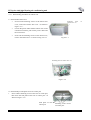
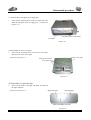
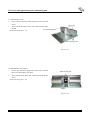
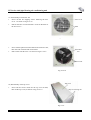
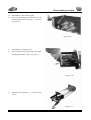
Outline drawing
1.1,
Unit outline drawing and combination example
1.3.1
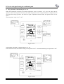
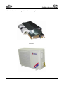
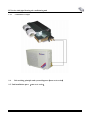
Outline drawing:
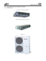
Indoor unit with round air supply port
Indoor unit with rectangle air supply port
Outdoor unit
FG Series wind pipe blowing air-conditioning unit
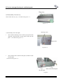
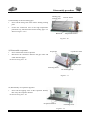
1.3.2
Example
Combination of small ducted type unit and indoor and outdoor units
1.1,
Unit working principle and system drawing
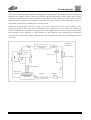
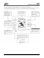
(a)working principle drawing of cooling only unit
COOL
Outdoor unit heat
exchanger
Compressor
Centrifugal fan
Capillary
Dry filter
Indoor unit heat
exchanger
Cooling circle: The compressor sucks the steam of the low-temperature and low-pressure cooling agent inside the
evaporator into the compressor. After it is compressed, it becomes the high-temperature and high-pressure gas and
is discharged into the condenser. Inside the condenser, the high-temperature and high-pressure gas of the cooling
-6-
System principle
agent performs the heat exchange with the outdoor air and passes the heat to the air, then it is condensate and
becomes the liquid of the high-temperature and high-pressure cooling agent. After its temperature and pressure are
lowered by the capillary throttle, it enters the evaporator. The gas-liquid 2 phase cooling agent in the evaporator
completely vaporizes and thus cools the indoor air. The steam from the evaporator is again sucked in by the
compressor and is compressed. It continuously circles this way. The cooled air which is operated by the fan, is
continuously sent to the air conditioning area from the air duct.
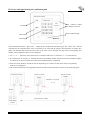
Heating circle: The heating circle is the reverse cycle of the cooling circle. At this time the four-way valve
changes the direction. That is, the steam discharged from the compressor enters the indoor heat exchanger to
become condensate. The condensate cooling agent passes the capillary throttle and then vaporizes in the outdoor
heat exchanger. After it vaporizes, it is again sucked in by the compressor and is compressed. It continuously
circles this way. The heated air which is operated by the fan, is continuously sent to the air conditioning area from
the air duct.
Cool
Heat
Outdoor unit heat
exchanger
Four-way
valve
One-way valve
Auxiliary Capillary
Compressor
Centrifugal fan
Electric heat
component
Capillary
Heat exchanger of
indoor unit
-7-
Dry filter
FG Series wind pipe blowing air-conditioning unit
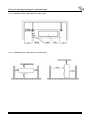
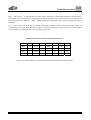
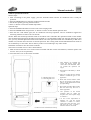
1.1, Installation space of the unit
1.5.1
Installation space requirements for indoor units
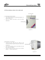
1.5.2
Installation space requirements for outdoor units
-8-
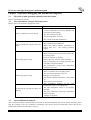
Technical parameter
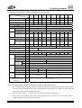
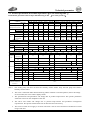
1.1, Product specifications and technical parameters
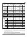
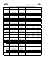
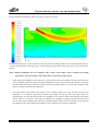
1.6.1 Performance parameter table for common excess pressure unit
Model FG6.5/ FGR6.5/ FG7.5/ FGR7.5/ FGD10/ FGRD10/ FG10/ FGR10/ FG12/ FGR12/
A
A
A
A
A
A
A
A
A
A
Item
W
6500
(Heat pump/auxiliary heat)
Dry capacity
W
-
kg/h
1.85
Air volume
m3/h
1250
1700
The static pressure of out unit
Pa
39
50
Cooling capacity
Heating capacity
Noise
7500
7500
7000
-
(1200)
1.85
10000
8000
-
(2100)
2.9
2.9
10000 10000 12000 12000
11000
(3600)
-
3.9
3.9
3.9
11000
-
(3600)
dB(A)
43
45
Outdoor
dB(A)
59
62
Starting current
A
A
11.7
-
12.2
13.8
14.0
10.4
-
(9.55)
12.9
(9.55)
15.8
16.2
-
15.3
(16.36)
6.7
3.9
5.4
5.4
7.0
8.2
8.4
6.7
-
(5.45)
-
13000
(3600)
8.1
(5.45)
A
56
56
70
70
90
90
45
45
55
55
Cooling
W
2400
2420
2600
2630
3370
3400
3600
3620
4530
4550
Heat pump/Auxiliary
heat
Max. power
W
3228
(3600)
-
7820
4300
W
-
2050
-
(2100)
3000
4300
2450
-
(2100)
3600
4600
4420
1.85
2.1
2.4
2.4
3.5
3.5
3.5
mm
mm
736
Height
mm
260
Net weight
Dimension of Length
air outlet Width
kg
37
49
mm
918
1155
mm
207
Width
mm
950
Depth
mm
Height
mm
700
kg
59
Diameter of water drainage pipe
(inside diameter×wall
thickness)
1074
3.4
Depth
Diameter of gas pipe
Connection
Diameter of liquid
pipe
pipe
8300
R22
kg
Width
Net weight
5800
Entirely close rotary
Refrigerant
Indoor unit
7400
4400
(3600)
3N~380V 50Hz
Entirely close
rotary
Compressor
Charge volume
3728
-
(3600)
~220V 50Hz
Power supply
Outdoor
unit
10000
Indoor
Cooling
Current Heat pump (auxiliary
electricity)
Power
6500
3.6
3.8
1395
412
700
1250
59
112
mm
Ф16
Ф19
mm
Ф9.52
Ф12
φ30×1.5
mm
Note: 1. The applicable standard for this unit design is GB/T18836-2002
2. The cooling/heating capacity in the above table is measured under the nominal operation condition when
the static pressure outside the unit is zero. The parameters will change as the products are improved. The
parameters on the unit nameplate shall prevail.
3. The size of the(lower)air return port is the same as that of the air supply port.
4. The noise is the measured value tested in the half silencing room. The real value of running will be
slightly higher due to the environment change.
-9-
FG Series wind pipe blowing air-conditioning unit
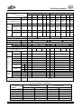
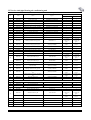
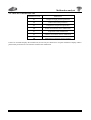
1.6.2 Performance parameter of multi-excess pressure unit
Cooling only
model
Heat pump
FG2.6H/A FG3.5H/A FG5H/A FG6.5H/A FG2.6H/A FG3.5H/A FG5H/A FG6.5H/A
Item
Cooling capacity
Heating capacity
W
2650
3500
5000
6500
(Heat pump/auxiliary
heat)
Cooling
Heat
Current
pump/Auxiliary
heat
COOL
W
-
-
-
-
A
4.2
5.6
8.9
12.0
Power
Heat
pump/Auxiliary
heat
Power supply
Compressor
Fan capacity l
Static pressure of out unit
Indoor
Noise
Outdoor
Diameter of water drainage
2900(300) 3700(800)
6.8
A
-
-
-
-
5.0(3.7)
6.1(3.7)
W
900
1320
1935
2550
930
1340
W
-
-
-
-
998(800) 1217(800)
~220V
m2/h
450
pa
dB(A)
dB(A)
5000
6500
5300(150
7200(2100)
0)
8.9
12
520
25-15
840
120-70
37
55
40
56
42
56
46
59
0.9
1.1
1.5
Ф6
Ф6
Ф9.52
Ф12
1935
2550
1849(150
2200/2100
0)
50Hz
Entirely close rotary
1400
450
60-40
8.54(6.82
10.9(9.55)
)
520
25-15
840
1400
60-40
120-70
37
55
40
56
44
57
46
59
1.85
0.94
1.15
1.7
2.1
Ф6
Ф9.52
Ф6
Ф6
Ф6
Ф9.52
Ф12
Ф16
Ф9.52
Ф12
Ф12
Ф16
913
680
220
27
515
102
750
172
980
736
276
36
738
125
738
207
1108
756
300
55
918
207
918
250
913
680
220
27
515
102
750
172
980
736
276
36
738
125
738
207
1108
756
300
55
918
207
918
250
mm
mm
mm
kg
760
250
530
32
760
250
530
40
950
412
700
59
760
250
530
32
760
250
530
40
950
412
700
59
mm
Ф20×1.5
Diameter of
mm
Connection liquid pipe
pipe
Diameter of gas
mm
pipe
mm
Width
mm
Depth
height
mm
weight
kg
Indoor unit
Dimension of Length mm
air outlet
Width mm
Dimension of Length mm
air returning Width mm
Width
Depth
height
weight
3500
4.5
Refrigerant
Filling volume of cooling agent(kg)
Outdoor
unit
2650
R22
Ф30×1.5
Ф20×1.5
Ф30×1.5
pipe( Outer X inner)
Note:1, The applicable standard for this unit design is GB/T18836-2002
2. The air quantity is measured under the excess pressure outside the corresponding standard unit.
3, The cooling/heating capacity in the above table is measured under the nominal operation condition when
the static pressure outside the unit is zero. The parameters will change as the products are improved. The
parameters on the unit nameplate shall prevail.
4, The static pressure of out unit is high static pressure--- standard static pressure could be changed by the
wires of the electric box, the setting is standard static pressure of leaving factory.
5, The noise is the measured value tested in the half silencing room, the real value of running will be slightly
higher due to the environment change.
- 10 -
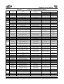
Technical parameter
Continuous table
model
Item
Cooling capacity
Heating capacity
(Heat pump/auxiliary
heat)
Cooling
Heat
Current
pump/auxiliary
heat
Cooling capacity
Heat
Power
pump/Auxiliary
heat
W
W
-
-
-
-
-
2200
(2100)
11000
(5600)
11200
(5600)
A
13.7
17.8
6.9
8.3
10.5
13.9
18.2
6.9
8.3
10.3
A
-
-
-
-
-
12.7
(9.55)
17.3
(16.36)
6.6/12.1
8.0
(5.45)
10.9
(5.5)
W
2800
3550
3800
4800
5200
2850
3580
3900
4800
5200
W
-
-
-
-
-
2555
(2100)
3400
(3600)
3500
(3600)
50Hz
3~330V 50Hz
~220V
Power supply
Compressor
Air volume
Static pressure of out unit
Noise
Indoor
Outdoor
Refrigerant
Cooling only
Heat pump
FGT.6H/ FGD20H/ FGD20H/ FG12H/ FG1G/ FGT.6H/ FGD20H/ FGD20H/ FG12H/ FG1G/
A
A
A
A
C
A
A
A
A
C
7500
10000
10000 12000 16000 7500
10000
10000
12000 16000
m2/h
1400
46
59
48
62
53
64
46
59
4475 5350
(3600) (3600)
3~330V 50Hz
2500
48
62
53
64
R22
2.4
Charge volume(kg)
Diameter of liquid
mm
Ф9.52
pipe
Connecti
on pipe Diameter of gas
mm
Ф16
pipe
Width
mm
1106
Depth
mm
756
Height
mm
300
Net
weight
kg
55
Indoor
unit
Dimension of air Length mm 918
outlet
Width mm 207
Dimension of air Length mm 1006
returning
Width mm 250
Width
Depth
Outdoor
unit
Height
Net weight
Diameter of water drainage
pipe( Outer X inner)
50Hz
Entirely close scroll compressor
2000
1400
2000
High static pressure 120pa Standard static pressure70pa
pa
dB(A)
dB(A)
~220V
15200 12000
(5600) (5600)
mm
mm
mm
kg
950
412
700
59
3.5
3.4
3.6
5.0
2.4
3.5
3.5
3.8
Ф12
Ф12
Ф9.52
Ф12
Ф12
Ф19
Ф22
Ф16
Ф19
Ф22
1463
756
300
72
1155
1463
756
370
95
1155
1106
756
300
55
918
1463
756
300
72
1155
1463
756
370
95
1155
207
1278
273
1278
207
1006
207
1278
273
1278
250
950
412
1250
112
320
950
412
1250
120
250
950
412
700
59
250
950
412
1250
112
320
Ф30×1.5
mm
Operation condition of conditioner:
Temp
Condition
Nominal cooling
Nominal heating
Max. cooling
Min. cooling
Max. heating
Low temp. heating
Indoor side status
Outdoor side status
Dry bulb temp.℃
Wet bulb temp.℃
Dry bulb temp.℃
Wet bulb temp.℃
27
20
32
18
24
15
19
--
23
14
18
--
35
7
43
18
27
-7
24
6
26
--
--
-8
- 11 -
5.0
FG Series wind pipe blowing air-conditioning unit
Chapter 2 Electricity and control
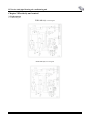
2. Light current
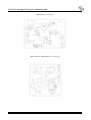
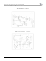
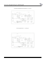
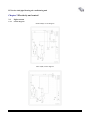
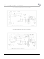
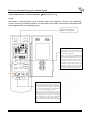
2.1.1 Circuit diagram
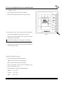
FGR2.6H/A(0) circuit diagram
FGR3.5H/A(0) circuit diagram
- 12 -
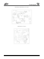
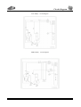
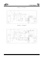
Circuit diagram
FGR2.6H/A(I); FGR3.5H/A(I) circuit diagram
FGR5H/A(0) circuit diagram
- 13 -
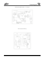
FG Series wind pipe blowing air-conditioning unit
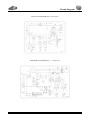
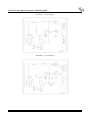
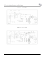
FGR5H/A (I) circuit diagram
FGR6.5H/A (0); FGR7.5HA (0): circuit diagram
- 14 -
Circuit diagram
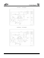
FGR6.5H/A(I);FGR7.5H/A(I)
circuit diagram
FG6.5/A(0); FG6.5H/A (0)
- 15 -
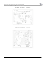
FG Series wind pipe blowing air-conditioning unit
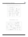
FG6.5H/A(I);
FG7.5H/A(I)
FGR7.5/A(0); FGR7.5H/A(0)
- 16 -
circuit diagram
circuit diagram
Circuit diagram
`
FGR6.5/A(I);FGR7.5/A(I) circuit diagram
FG7.5/A(0);FG7.5H/A(0)
- 17 -
circuit diagram
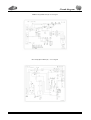
FG Series wind pipe blowing air-conditioning unit
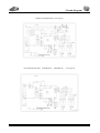
FG7.5/A(I);FG6.5/A(I) circuit diagram
FGRD10/A(0);FGRD10H/A(0)
- 18 -
circuit diagram
Circuit diagram
FGD10/A(0);FGD10H/A(0) circuit diagram
FGRD10H/A(I);FGRD10/A(I)
- 19 -
circuit diagram
FG Series wind pipe blowing air-conditioning unit
FGR12/A(0);FGR10/A(0);FGR12H/A(0); FGR10H/A(0) circuit diagram
FGR12H/A(I);FGR10H/A(I)
- 20 -
circuit diagram
Circuit diagram
FGR12/A(I);FGR10/A(I) circuit diagram
FG12/A(0);FG10/A(0);
FG12H/A(O);
- 21 -
FG10H/A(0)
circuit diagram
FG Series wind pipe blowing air-conditioning unit
FG12H/A(I);FGD10H/A(I);FG10H/A(I) circuit diagram
FG12/A(I);FG10/A(I)
- 22 -
circuit diagram`
Control logic
List of wiring
Please note: The length of all signal cables and power cables must be within 15 meters.
- 23 -
FG Series wind pipe blowing air-conditioning unit
2.2 Light current
2.2.1 Operation mode
1.
Temperature parameter
(1)
The room ambient temperature T amb
(2)
The evaporator tube temperature T tube
(3)
The condenser tube temperature T defrost
(4)
Outdoor environment temperature T outdoor
(5)
Air discharge pipe temperature T dis
2. Basic function
After the power is on, no matter when compressor is started, the time span between the startups cannot be less than 3
minutes. When it is powered for the first time, the compressor does not have the time delay of 3 minutes. Once the
compressor starts up, it will not shut down due to the temperature change within 6 minutes.
2.1 COOL mode
2.1.1 Cooling condition and process
If T amb>T set, COOL mode will act, compressor and external fan will run, the indoor fan will run at the set speed.
If T amb<T set, the unit will stop, it is cooling now , compressor and external fan will stop, the indoor fan will run at
the set speed.
If T amb=T set, the compressor and external fan will keep running in the old mode, the indoor fan will run at the set
speed.
The setting temp. range is 16℃~30℃. The indoor fan will run at the set speed and there are three air speeds to be
selected. All malfunctions are checked during the operation of the compressor. Corresponding treatments will be
provided for any malfunctions.
2. 1.2 Antifreezing Protection
When the antifreezing protection is detected (LCD displays E2), the compressor and the external fan will stop, the
indoor fan will run at the set speed. when antifreezing protection is eliminated and compressor has stopped for 3min, the
whole unit will run at the original status.
2.2 dry mode
If T amb>T set +2℃, the cooling and drying mode will act, compressor and external fan will run, indoor fan will
run at low speed
If T set =T amb, after the external fan and compressor running for 6mins, it will stop about 4 mins, The processes
are shown as the above cycle. indoor fan will run at the low speed.
If T amb<T set, the compressor and the external fan will stop
The setting temp. range:16℃~30℃. indoor fan will run at the set speed. All malfunctions are checked during the
operation of the compressor. Corresponding treatments will be provided for any malfunctions.
2.2.1Anti-frost protection(same as cooling).
2.3 air supply mode
- 24 -
Control logic
The indoor fan will run at the set speed and there are three air speeds to be selected. The speed of the air supply in
the automatic mode is the intermediate speed.
In the air supply mode, when there are fan malfunction and communication malfunction, the unit will shut down.
Other malfunctions will be display without the shutdown of the unit.
2.4 HEAT Mod(The cooling only unit does not have the heating mode. If the cooling only unit does not respond to
the remote control heating signal, then it is still in the air supply mode.)
2.4.1 Conditions and processes of heating
1 If T amb <T set, the heating operation will begin and the change valve, the external fan and the compressor
are respectively powered and put into operation. The indoor fan operates based on the set air speed and the cool
air condition.
1 If T amb=T set, the compressor, external fan and reversing valve will keep running in the old mode. Indoor fan
will run at the set speed
1 If T amb>T set, Compressor and external fan will stop, reversing valve will keep working, indoor fan will blow,
after 60secs it will stop.
1 The setting temp. range:16℃~30℃
2.4.2 Anti-cool-air operation protection
When the compressor restarts after it stops or when the defrosting ends, the internal fan will begin to run after the
compressor runs for some time. If the compressor does not start up, the internal fan will stop operation.
2.4.3 Indoor anti-high-temperature protection
During the heating operation, when the pipe temperature of the evaporator is detected to be too high, the external
fan will stop operation. When the pipe temperature of the evaporator is normal, the external fan will resume
operation.
During the indoor high-temperature protection period, other protections (if any) will be treated as the normal
protection. However, if the over current of the compressor or the high temperature of the air discharge pipe is
detected and these two protections can resume operation themselves, then after resuming, if the
anti-high-temperature does not quit, then the indoor high-temperature protection shall continue.
2.4.4 Conditions and processes of defrosting
After the heating operation, when the frost of the condenser is detected, the system enters the defrosting status. At
this time, the four-way valve, the external fan and the auxiliary electric heating stop operation. The compressor
performs the forced operation and the internal fan operates based on the anti-cool-air condition. When it is
detected that he frost on the condenser has been removed, the four-way valve and the external fan begin to operate
and then the internal fan begin to operate.
For defrosting, the defrosting time will be adjusted based on the frosting condition on the condenser. If there is
much frost, the defrosting time is long(maximum of 10 minutes). If there is not much frost, then the defrosting
time is short. When it is detected that the defrosting has ended, quit the defrosting mode.
2.5 AUTO mode.
In this mode, the system can select the mode automatically according to the ambient temperature
3. Other control
3. 1 Timing Control.
TIMER OFF: Set the timer for turning off function when the unit is turned on, the PCB will act in the set mode ,when
it is time to turn off, the unit will be switched off.
TIMER ON: The unit is stopped when the timer for turning on acts. When it is time to turn on, the PCB will act in the
set mode.
- 25 -
FG Series wind pipe blowing air-conditioning unit
The time range is 0.5-24 hours.
3.2 Energy saving
For heating, press the ENERGY SAVE button, after half an hour, the T set will decrease by 1℃. After 1 hour, the
T set will decrease by 2℃.
For cooling, press the ENERGY SAVE button, after half an hour, the T set will increase by 1℃. After 1 hour, the
T set will increase by 2℃.
3.3 Test function
In the first power-on status, press the temperature selection button (TEMP▲) to enter the heating status. The
compressor is on, the four-way valve is on, the internal fan runs at high speed and the auxiliary electric heating is
on. After the operation for 5 minutes, the unit automatically shuts down. You may also press the ON/OFF button
to stop the test.
In the first power-on status, press the temperature selection button (TEMP▼) to enter the cooling status. The
compressor is on, the four-way valve is on, the internal fan runs at high speed and the auxiliary electric heating is
on. After the operation for 5 minutes, the unit automatically shuts down. You may also press the ON/OFF button
to stop the test.
3.4 Remote control function
The wire controller may receive the remote control instruction. When the remote control receiving is made, the
buzzer will sound to make indication. The remote controller will screen the useless buttons. The wire controller
only receives the four remote control instructions from the remote controller, i.e. ON/OFF, mode, air speed and
temperature setting. The remote controller does not receive the shutdown instruction when the system has any
malfunction and the ON/OF button on the wire control panel must be pressed in order to shut down the unit.
3.5 Communication function
The communication distance between the mainboard and the wire control panel may reach 20 meters(the standard
distance provided is 8 meters).
3.6 Key lock function of manual controller
The function should be similar to that of the cellphone. Press the temperature selection button (TEMP▲) and the
temperature selection button (TEMP▼) and the key will be locked. The screen will display EE. Press them again
to release the lock.
3. 7 High temperature protection for air discharge pipe of compressor
After the compressor starts up, if it is detected that the air discharge temperature of the compressor is too high,
then shut down the compressor and the external fan and the unit enters the protection status.
When it is detected that the air discharge temperature is normal, then the compressor restarts the operation. From
the detection of the first malfunction, if the high temperature protection for the air discharge pipe is consecutively
detected for 3 times within 30 minutes, the high temperature protection E4 for the compressor will be displayed
and the buzzer will sound the alarm. The unit can not be automatically resumed. Press the NO/OFF button to shut
down the unit and clear the sound alarm.
3.8 Communication Malfunction
1 After it is powered, if the outdoor unit does not receive the feedback from the mainboard of the indoor unit, it
- 26 -
Manual controller
will be regarded as a communication malfunction of the indoor unit. The compressor and the external fan stop
and the malfunction codes are displayed. At the same time, if the indoor unit does not receive the information
from the outdoor unit, then the indoor unit stops the auxiliary electric heating and the internal fan. If the manual
controller does not receive the information from the outdoor unit, the malfunction E6 will be displayed and the
unit does not run.
1 After the communication is back to normal, the system will operate according to the previous operation status.
3.9 Temperature sensor malfunction
1 3. 9. 1 Indoor environmental sensor: If there is any open circuit or short circuit for the indoor temperature
sensor,“F0”will be displayed. After the malfunction is eliminated, the unit will automatically resumes the
operation. In the air supply mode, only the malfunction code is displayed and the internal fan operates normally.
After the malfunction is cleared, the malfunction code disappears.
1 3.9.2 Indoor evaporator sensor: If there is any open circuit or short circuit for the evaporator temperature sensor,
“F1”will be displayed. After the malfunction is eliminated, the unit will automatically resume the operation
and clear the malfunction code. In the air supply mode, only the malfunction code is displayed and the internal
fan operates normally. After the malfunction is cleared, the malfunction code disappears.
1 3.9.3 Condenser temperature sensor: If there is any open circuit or short circuit for the condenser temperature sensor,
“F2”will be displayed. After the malfunction is eliminated, the unit will automatically resumes the operation
and clears the malfunction code. In the air supply mode, only the malfunction code is displayed and the internal
fan operates normally. After the malfunction is cleared, the malfunction code disappears.
1 3.9.4 Malfunction of outdoor environmental sensor: No matter the unit is on or it stands by, if the malfunction
of the outdoor temperature sensor is detected, then no treatment is made to the outdoor temperature sensor and
only the temperature sensor malfunction code F3 is displayed.
1 3. 9. 5 Air discharge temperature sensor malfunction : If there is any open circuit or short circuit for the air
discharge temperature sensor, the malfunction code“F4” will be displayed and the buzzer will sound the alarm.
After the malfunction is cleared, the unit will automatically resumes the operation and clear the malfunction
code.
- 27 -
FG Series wind pipe blowing air-conditioning unit
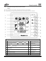
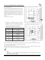
2.2.2 Description and usage instruction for manual controller
2.2.2.1 Name and function of each button of wire controller
ON/OFF button:
Press this button, the air
condition will start to
operate. Press it again
and the air conditioner
will stop operation.
As shown in Fig 2.2.2:1-1
Mode button: press the
button once and the air
speed will change in the
following order:
Liquid crystal displayer:
to display the information
selected by each button.
Automatic Cooling
Heating
Cry
Air supply
Timing
switch
ON/OFF
Fan control button: press
the button once and the
air speed will change in
the following order.
Hour
Mode
Swing
Automatic air
speed
Fan control
Automatic High Middle Low
Sleep
Set
Defrosting Environment
Temperature adjustment
Sleep
-Test
Timing
Automatic Cooling
Mode
Dry
Air supply Heating
SLEEP button: press it
once and the unit is in
the sleep status, press it
again to quit the sleep
status.
Temperature button: press
△ once and the set
temperature rises by 1℃,
press ▽ once and the set
temperature drops by 1℃.
Timing button: in the ON(OFF)
status, the timed ON(OFF) time can
be set respectively. Press the button,
each time the set time rises by 0.5
hour.
It circles in the following way:
24 hours
Cancel timing
2.2.2.2 Wire controller operation:
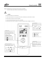
1) Cooling operation method, as shown in Fig 2.2.2.2-1
The microcomputer will decide whether to start up cooling or not based on the difference value between the
temperature sensed by the room temperature sensor and the set temperature.
When the temperature sensed by the indoor temperature sensor is higher than the set temperature, the cooling
operation begins.
When the temperature sensed by the indoor temperature sensor is lower than the set temperature, the cooling
operation stops and the indoor fan blows.
The setting temp. range is 16℃~30℃
- 28 -
Manual controller
1. After the power is
on, press the ON/OFF
button
and
the
conditioner is in the
operation mode.
2. Press the mode
button to select the
cooling method.
Timing
switch
ON/OFF
Hour
Automatic
air speed
Fan control
Mode
Sleep
Set
3. Press the fan control
button to set the air
speed.
Swing
Defrosting Environment
Temperature adjustment
Sleep
4. Press the temperature
button to set the required
temperature.
Test
Automatic Cooling
Dry
Timing
Mode
Air supply Heating
Fig 2.2.2.2-1
2) Heating operation, as shown in Fig 2. 2. 2. 2-2
When the temperature sensed by the indoor temperature sensor is lower than the set temperature, the compressor
begins to run and the heating operation begins.
When the temperature sensed by the indoor temperature sensor is higher than the set temperature, the compressor
and the outdoor fan stop and the indoor fan blows.
In heating, when the outdoor temperature is low but the humidity is high, the outdoor unit will frost and leads to
the low efficiency of the heat supply. At this time, the controller will automatically begin the defrosting circle and
display defrosting.
The setting temp. range is 16℃~30℃
1. After the power is
on, press the ON/OFF
button
and
the
conditioner is in the
operation mode.
2. Press the mode
button to select the
cooling method.
Timing
switch
ON/OFF
Hour
Automatic
air speed
Fan control
Mode
Sleep
Set
3. Press the fan control
button to set the air
speed.
Swing
Defrosting Environment
Temperature adjustment
Sleep
Test
Timing
Automatic Cooling
Dry
Mode
Heating
Air supply
Fig 2.2.2.2-2
- 29 -
4. Press the temperature
button to set the required
temperature.
FG Series wind pipe blowing air-conditioning unit
3)
Dry operation, as shown in Fig 2. 2. 2. 2-3
When the temperature sensed by the indoor temperature sensor is between ±2℃, the unit enters the dry
operation. When the temperature sensed by the indoor temperature sensor is higher than the set temperature, the
unit begins the cooling operation. The indoor air speed is adjustable and the outdoor fan operates with a low air
speed.
The setting temp. range is 16℃~30℃
1. After the power is on,
press the ON/OFF
button
and
the
conditioner is in the
operation mode.
2. Press the mode
button to select the
dry method (the air
speed can not be
changed after dry is
selected).
Timing
switch
ON/OFF
Hour
Swing
Mode
Automatic air
speed
Fan control
Sleep
Set
Defrosting Environment Temperature adjustment
Sleep
3. Press the temperature
button to set the required
temperature.
Test
Timing
Automatic Cooling
Mode
Dry
Air supply Heating
Fig 2.2.2.2-3
4) Automatic operation, as shown in Fig 2. 2. 2. 2-4
In the automatic mode, the standard cooling set temperature is 26℃. The standard heating set temperature is 20℃.
1. After the power is on,
press
the
ON/OFF
button
and
the
conditioner is in the
operation mode.
Timing
switch
ON/OFF
Hour
Swing
Automatic air
speed
Fan control
Sleep
Set
Defrosting Environment
Sleep
Test
Timing
Mode
2. Press the mode button to
select
the
automatic
method.
The
microcomputer
will
automatically
select
cooling, heating or dry to
achieve comfortable effect
based on the indoor
temperature.
Automatic Cooling
Mode
Dry
Air supply Heating
Fig 2.2.2.2-4
- 30 -
Temperature adjustment
Manual controller
5)
SLEEP mode operation, as shown in Fig 2. 2. 2. 2-5
In COOL and DRY mode, setting the SLEEP mode, the setting temp. will be increased
1℃ in the first hour, and it will be increased 2℃ in the second hour. In HEAT mode, setting the SLEEP mode,
the setting temp. will be decreased 1℃ in the first hour, it will be decreased 2℃ in the second hour.
ON/OFF button:
Press this button, the air
condition will start to
operate. Press it again
and the air conditioner
will stop operation.
Mode button: press the
button once and the air
speed will change in the
following order:
Liquid crystal displayer:
to display the information
selected by each button.
Automatic Cooling
Heating
Cry
Air supply
Timing
switch
ON/OFF
Fan control button: press
the button once and the
air speed will change in
the following order.
Hour
Mode
Swing
Automatic
air speed
Fan control
Automatic High Middle Low
Sleep
Set
Defrosting Environment
Temperature adjustment
Sleep
-Test
Timing
Automatic Cooling
Mode
Dry
Air supply Heating
SLEEP button: press it
once and the unit is in
the sleep status, press it
again to quit the sleep
status.
Timing button: in the ON(OFF)
status, the timed ON(OFF) time can
be set respectively. Press the button,
each time the set time rises by 0.5
hour.
It circles in the following way:
24 hours
Cancel timing
Fig 2. 2. 2. 2-5
- 31 -
Temperature button: press
△ once and the set
temperature rises by 1℃,
press ▽ once and the set
temperature drops by 1℃.
FG Series wind pipe blowing air-conditioning unit
Integrated controller
ON
All rooms
Unit
selection
ON button
Unit selection button.
the default is all units.
OFF
Power indicator light
OFF button
Unit display
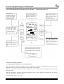
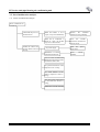
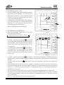
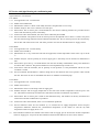
This centralized controller(upper unit) adopts the 485 method and the ducted type unit(lower unit)manual
controller for the communication. It has a maximum of 16 units and the longest control distance is 1200m. The
upper unit automatically detects the lower unit. If the lower unit is detected, the digit of the corresponding unit
number will be displayed, others are not displayed.
1. Use △ or ▽ buttons to select the unit to be controlled. There are 17 selections, i.e. 1~16 and all units.
2. If a certain unit(or all units)is selected, then the corresponding number will flash. Press the ON button and the
unit starts up. At this time the frame of the corresponding number is displayed.
3. Press the “OFF” button to shut down the corresponding unit. At this time the frame of the corresponding
number is not displayed.
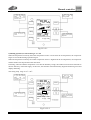
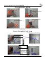
4. The connection between this integrated controller and the manual controller is shown in the following figure.
Integrated controller
Manual controller
Manual controller
Display
Display
Maximum of 16 groups
看不清
看不清
Power:
Longest distance: 1200m
Switching
power
- 32 -
看不清
Centralized control
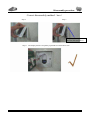
Function note:
.
If the “all selection” is selected, the lower units will be started up by pressing the ON button. Considering the
interference to the electric network, if more than one unit are started up, there is a time delay of 10 seconds for the
starting up of each unit. Press the “OFF” button to shut down all the lower units. There is no time delay for the
shutdown.
If“1”or those above the single unit is selected, pressing the “ON/OFF” button will start up and shut down the
corresponding lower units. Note: Because the upper unit keeps enquiring the 16 lower units, there is a time delay
of 16 seconds from pressing the button to the response of the unit.
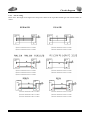
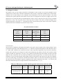
Relation between dial code switch position and unit No.
Position
No.
Position
No.
Position
No.
Position
No.
0000
1
0100
5
1000
9
1100
13
0001
2
0101
6
1001
10
1101
14
0010
3
0110
7
1010
11
1110
15
0011
4
0111
8
1011
12
1111
16
Note: If this control function is needed, instruction must be made before ordering goods.
- 33 -
FG Series wind pipe blowing air-conditioning unit
Chapter 3 Operation debugging and malfunction diagnosis
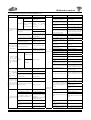
3.1 List of unit operation conditions and check items
No.
1
2
3
4
5
6
7
8
9
10
11
12
13
14
15
16
17
18
19
20
Items to be checked
Please refer to the installation manual and check whether the machine is placed at the appropriate position,
whether the surrounding space is reasonable and whether the unit needs the shock-absorption treatment.
Check whether the caliber of the air duct is appropriate(the air speed of the air duct is not more than 3.5m/s),
whether it affects the installation at the air port.
Check whether there is any filter screen for the air return box, whether the size and the quality of the filter screen
are correct, whether it is clean and at the right position.
Check whether the opening size and the position of the air outlet and the air return port comply with the
requirement (air return port must be repairable) and make the record.
Check whether the condensation water basin has any dirt and clean it if any
Check whether the slope of the condensation water pipe complies with the requirement, whether the water flow
is smooth(water need to be poured to test it)
Check whether the fixing screws between the indoor unit motor and the fan are loose, whether the fan blade can
rotate freely without any friction or touch
Understand the installation soldering techniques for the secondary refrigerant, check whether the dirt produced
by the soldering are cleaned, whether the diameter, thickness, heat insulation and waterproofness of the copper
pipe are correct
Check the nitrogen gas pressure of the outdoor unit and make the record. The outdoor temperature is____
℃, the nitrogen gas pressure is ___________kg/cm2(bar). If the nitrogen gas pressure is not normal, the
installation personnel must be requested to check the leakage point.
If the nitrogen gas pressure is normal, slowly release the nitrogen gas of the connection pipe and the indoor unit
until it is all released. Connect the vacuum pump to the thimble valve (if any) of the liquid pipe and the gas pipe,
and vacuumize them simultaneously from the liquid pipe side and the gas pipe side
Check whether the connection of the indoor and outdoor units comply with the wiring diagram of the unit,
whether the wire path is appropriate, whether the connection terminal is fastened
Check whether the power distribution facilities such as the wire path, the model of the shutdown/air switch of
the indoor and outdoor units and _________are reasonable
Check whether the embedded terminal box of the temperature controller is elegant and complies with the switch
box, whether it complies with the specifications
Install the temperature controller and check whether the wiring of the temperature controller is correct, whether
the position is appropriate and turn the temperature controller at the OFF position
Cover the temperature controller with the protection bag to avoid any decoration damage or pollution of the
temperature controller
The vacuumizing time is about 25-30 minutes. Check whether there is any air discharge at the air discharge port
of the vacuum pump (use the hand to plug up the air discharge port for 3 minutes and no air should be
discharged, no air bubble shall appear in the oil of the vacuum pump and at the outlet).
Use the hexagon ring spanner to open the maintenance valve of the liquid pipe for 2-3 seconds and then shut it
immediately to see whether there is any gas out. If there is, it indicates that the connection of the liquid adding
pipe with the maintenance valve and the vacuum pump is smooth without any block. Continue vacuumizing for
5 minutes.
If the vacuum pump always has air bubbles, check the sealing of the vacuum pump or check for leakage, causes
must be found before the next step is taken.
Calculate the adding volume of the secondary refrigerant, for the air conditioner which has been filled with the
secondary refrigerant by the factory, {actual pipe length__-5m(the factory-filled secondary refrigerant has
included the secondary refrigerant of the 5-meter pipe length)} × _ _ g/m ﹦ secondary refrigerant
supplementation volume___gram
For the unit model with unknown secondary refrigerant filling volume, please refer to the unit nameplate and use
a small filling volume as the operation test to record the final filling volume.
Shut the manual valve connected by the liquid adding pipe(maintenance tool). Connect the steel bottle of the
secondary refrigerant (at this time the steel bottle of the secondary refrigerant in placed on the electronic scale),
slightly open the steel bottle valve, screw and tighten screw thread of the other side of the liquid adding pipe that
connects to the steel bottle to discharge the air in the liquid adding pipe. Record the readings on the electronic
scale. The reading is_____gram.
- 34 -
√
Check list
Attached table
√
No.
Items to be checked
21
Final reading of the electronic scale calculated=initial reading of the electronic scale_gram-
supplementation volume of secondary refrigerant_gram=_gram
22
Open the valve of the secondary refrigerant steel bottle and the manual valve of the liquid
adding pipe, observe the reading of the electronic scale. When the reading of the electronic
scale is close to the final reading calculated, tighten the manual valve of the liquid adding pipe
and record the actual added liquid volume.
Actual supplementation volume of
secondary refrigerant_gram
23
Connect the outdoor unit power cable and the plug, but do not supply power.
24
Use the resistance level of the universal meter to measure the resistance between the power
plugs L, N and E(grounding) and use it as the basis to judge whether there is any short circuit
of the power and make the record
Single-phase power L and N_, L and E_, N and E_. If
it is the three-phase power, then measure the resistance between A and B_, B and C_, A and C
_
A and N_, B and N_, C and N_ and the resistance between A, B, C and the ground
A and E_, B and E_, C and E_
25
Measure the supply voltage of the power socket and make the record. The single-phase power L
and N_V,
The three-phase power A and B_V,B and C_V. A and C_V,
A and N_V, B and N_V, C and N_V
26
Check whether the position of the air volume adjustment valve on the air port and the air duct of
the indoor unit is appropriate
27
Check whether the
Supply voltage_V
28
Measure whether the voltage supplied from the main power to the terminal of the indoor and
outdoor unit is normal and make the record
Supply voltage on the terminal_V
29
Unit operation cooling test, indoor temperature_℃, outdoor ambient temperature_℃
30
Unit operation heating test, indoor temperature_℃, outdoor ambient temperature_℃
main
supply
voltage
is
normal
and
make
the
record
FG Series wind pipe blowing air-conditioning unit
3. 2 List of malfunction analysis
3. 2. 1 Flow of malfunction analysis
The air conditioner can
not start up
The breaker trips out(or
When the breaker is set at
the fuse blows)
“open”, it trips out immediately.
Measure
the
insulation
resistance for the grounding.
When the air conditioner is
turned to “open”, the breaker
trips out in a few minutes.
Check
the
breaker.
Measure the resistance for
the short circuit.
Neither the indoor unit
nor the outdoor unit can
start up.
No power supply
Malfunction of remote
controller transmission
There is a serial communication
malfunction between the indoor
unit and the outdoor unit.
The protection function of the
compressor coil is acting.
The cutoff function of the
locking compressor motor is
acting
The open circuit of the sensor
or the moderation function is
acting.
Malfunction of switch assembly
- 36 -
Check
the
supply status
Check
controller
power
remote
Malfunction analysis
3.2.2 Malfunction analysis as shown in table 3.2.2-1
Phenomenon
Possible causes
Recovery method
Power failure
Resume the power
Four-way valve malfunction
Replace four-way valve
Eliminate the short circuit and
replace the fuse
Local block of the capillary
Replace capillary
Short circuit
Phenomenon Possible causes
Recovery method
Leakage between the internal high
Replace compressor
and low pressure of the compressor
The fuse blows. Circuit
grounding Eliminate
the
grounding
malfunction
malfunction or replace
the
(insulation damage)conducting wire
The pipeline valve is not adjusted to
Adjust the valve to be sufficient
be sufficient
Secondary refrigerant leakage
Neither the indoor unit
nor the outdoor unit
Eliminate the bad contact
The power plug is not well inserted or
can operate
has bad contact
Firmly insert it into the socket
Check the leakage source and
supplement the secondary refrigerant
The thermal insulation of the
The thermal insulation for the strong
connection pipe between the indoor
pipe and the slim pipe are separated
and the outdoor unit is bad
Check the circuit based on the
The connection between the indoor
electric diagram and make the
unit and the outdoor unit is wrong.
correct connection
The heating load is too big
Check the predicted heating load
The set temperature is too low
Increase the set temperature
The protector tube of the controller Replace the protector tube of the
blows.
controller
The installation position of the Good ventilation must be provided at
outdoor unit is not appropriate
the outdoor side
The controller is burned out.
The filter screen of the indoor unit Clean the filter screen regularly
is blocked.
Replace the controller
The heat exchanger of the outdoor Clean the heat exchanger of the
The indoor fan and the motor are
unit is blocked.
outdoor unit
Repair or replace the fan motor
The switch is at the air
burned out or disconnected.
The air that passes the indoor heat Increase the rotation speed of the
supply position, but
exchanger is little
motor
the fan does not run
Eliminate the malfunction or
Compressor malfunction
Replace the compressor
Remote controller malfunction
The
heating
replace the remote controller
Four-way valve malfunction
Replace the four-way valve
effect is not good
Leakage of the one-way valve of the
Replace the one-way valve
outdoor unit
Coil disconnection
The operation mode
is at the ”cool”
Relay
or ”hot” position,
malfunction
neither the outdoor fan
nor the compressor
operates
The capillary is blocked
Replace the capillary
Defrosting is not thorough
Replace the defrosting temperature
sensor
The pipe valve is not adjusted to be
Adjust the valve to be sufficient
sufficient
Replace the relay
Insufficient secondary refrigerant
Bad contact
Find out the leakage source and
supplement the secondary refrigerant
The thermal insulation of the
The thermal insulation for the strong
connection pipe between the indoor
pipe and the slim pipe are separated
and the outdoor unit is bad.
The indoor unit fan touches other
Adjust the fan position
objects
The operation mode is
Malfunction of the outdoor fan motor Replace the motor
at
the
“cold”or”hot”position, Outdoor unit relay malfunction
Replace the relay
the
compressor
Bad contact between the defrosting Replace
the
defrosting
operates
but
the
temperature sensor and the pipe temperature sensor and the pipe
outdoor fan does not
temperature sensor
temperature sensor
operate.
Adjust the supporting pad of the
The compressor vibrates too much. compressor and fasten the loosened
bolts
There are foreign matters in the
Eliminate the foreign matter
indoor unit
Compressor malfunction
Replace the compressor
The operation mode is
at the “cold” or ”hot”
position, the outdoor
fan operates but the The capacitor is burned out during the
Replace the capacitor
compressor does not compressor operation
operate.
Abnormal sound
and vibration
The cooling load is too large.
Check the predicted cooling load
The set temperature is too high.
Lower the set temperature
Avoid direct installation on the steel
Much resonance is produced when window
the air conditioner indoor unit is Install it on a thick wall with
installed on the panel wall or the appropriate strength
thin wall
Take appropriate shock-absorption
measures
The pipes of the outdoor unit touch Separate the pipes that touch each
each other
other
Screw down the fitting screw
Good ventilation must be
provided at the outdoor side and
The installation position of the
The cooling effect is
weatherproof
and
cooling machine is inappropriate.
not good in the cooling
solarization-proof board must be
mode
appropriately provided.
Metals inside the unit touch each
Affix the adhesive between the metal
other
boards
The filter screen of the indoor unit is
Clean the filter screen regularly
blocked.
The outdoor unit fan blade touches
Adjust fan position
the shell
The heat exchanger of the indoor unit
Clean the heat exchanger
is blocked
There is abnormal sound in the
Replace the compressor
compressor
The fan rotation speed set is too low
Set it to be high speed or middle
speed
- 37 -
In heating, there is electromagnetic There is short circuit in the magnet
sound in the four-way valve
valve. Replace the magnet valve
FG Series wind pipe blowing air-conditioning unit
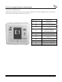
3 Check list of malfunction code
When there is malfunction existing in system running, malfunction code will be displayed on the wire controller.
The meanings of the malfunction codes are in table 3.3.1.
Malfunction Code
Malfunction
E1
Protection of compressor high
pressure, etc
E2
Indoor anti freezing protection
E3
Compressor low-presser
protection
E4
Compressor discharge
temperature protection
E5
Compressor overload protection
E6
Communication malfunction
F0
Indoor temperature sensor
malfunction
F1
Evaporator sensor malfunction
F2
Condenser sensor malfunction
F3
Outdoor sensor malfunction
F4
Air outlet sensor malfunction
- 38 -
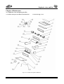
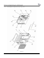
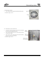
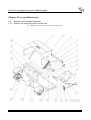
Explosive view and list
Chapter 4 Maintenance
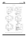
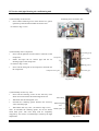
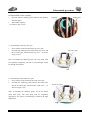
4. 1 Explosive view and spare parts list
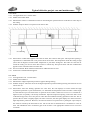
4.1.1 Indoor unit parts breakdown and check list
As shown in Fig 4.1.1-1
Fig 4.1.1-1 Indoor unit parts breakdown
- 39 -
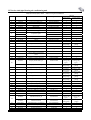
FG Series wind pipe blowing air-conditioning unit
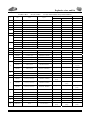
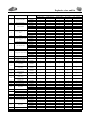
FG(R)2.6H/A,FG(R)3.5H/A Indoor unit parts breakdown
Quantity
No.
Code
Name
Fig No.
FG(R)2.6H/A
FG(R)3.5H/A
1
2
3
4
5
6
7
01259056
0129054
12579051
01499055
15019053
15002401
01339062
Cover board of air return
Lower cover plate assy
Water container parts
Air return port side plate assy
Motorfg20c
Fan motor(left type)
Fan mounting plate
FGR2I 02000002
FGR2I 02000000
FGR2I 08000000
FGR2I 06000000
FG3HAI 02010001
GST4238LAI 03000000
FGR3HAI 03010000
1
1
1
1
1
1
1
1
1
1
1
1
1
1
VJ25P 04000000
1
1
1
1
1
4
1
2(used by
heat pump)
1
1
1
4
1
2(used by heat
pump)
1
1
1
1
TY13.02.82(01)
1
1
TY13.04.03(17)
30505.0021MX
1
1
1(used by
cooling only
type)
2(used by
heat pump)
1
2(used by
heat pump)
2(used by
heat pump)
1(used by
heat pump)
1(used by
heat pump)
1
1
1
1
1(used by
cooling only
type)
2(used by heat
pump)
1
2(used by heat
pump)
2(used by heat
pump)
1(used by heat
pump)
1(used by heat
pump)
1
1
1
1
1
1
1
1
1
1(used by
cooling only
type)
1(used by
heat pump)
1
1
3
2
1
1(used by
cooling only
type)
1(used by heat
pump)
1
1
3
2
8
01008704
Evaporator parts
9
10
11
12
01009058
01079055
01309051
02112446
01408627
Evaporator left bracket
Left side plate parts
Hook
Electric box assy
FGR3HAI 10000000
FGR3I 11000002
FGR2I 04000000
(2641PA)05010007
FGR5I 07010000
13
01222024
Heating element locking parts
(3551PA)1000106
15
460124051
Thermal protector assy
16
01492476
17
390000451
18
19
3900018717
305050021
Air return port side plate assy
Indoor ambient temperature
sensor
Indoor pipe temperature sensor
Remote controller ZY502A
30294401
Display board Z4415_M
30294.401MX
30294010
Display board Z4435_M
30294.010MX
21
01259051
Upper cover plate parts
FGR2I 01000000
22
32012005
Electric heater
(3551PA).10090105
23
01222024
Heating element locking parts II
(3551PA).10090106
24
01738702
Heating element bracket 2
VJ25P03000002
25
01738701
Heating element bracket 1
VJ25P.03000001
26
27
28
29
30
31
32
33
01309054
01079056
Right side plate parts
Evaporator right bracket
FGR2I 05000000
FGR3I 11000001
15002401
44010234
33010020
Fan motor(right type)
AC contactor GC8-30
Capacitor CBB611.5μF/450V
43000209
Power transformer SC39
QJ/GD.53.12
/
TY.11:01.37
30224403
Mainboard Z4415_M
30224403MX
30224001
Mainboard Z4035
30224001MX
420111562
70410524
71010102
42011103
Terminal board(5 positions)
Insulation spacer F
Electric wire holder
Terminal board 2-8
TY.14.04.02(02)
TY.00.84a
LF7.5WB.06000001
TY.00.205
14
(2551PA010090200b(01
)
(2641PA)09000000
20
/
GST4238LAI 03000000
34
35
36
37
38
- 40 -
Explosive view and list
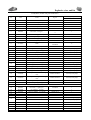
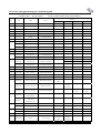
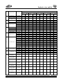
FG(R)5H/A, Indoor unit parts breakdown
Fig No.
Quantity
No.
Code
Name
1
01258650
Cover board of air return
FGR5I.00000006
1
2
01258649
Lower cover plate assy
FGR5I 02000001
1
3
01278633
Water container parts
FGR5I 06010000
1
4
01499061
Air return port assy
FGR5HAI.09010000
1
5
15018322
Motor FG70B
FGR5I 00000003a
1
1
FG(R)5H/A
6
15002401
Fan motor(left type)
GST4238LAI.0300000
0
7
01339058
Fan mounting plate assy
FGR5HAI 03020000
1
8
01339058
Evaporator parts
FGR5I 08000000
1
9
01078626
Evaporator left supporting bracket
FGR5I 00000005
1
10
01308668
Left side plate parts
FGR5I 04010000
1
Hook
KFR80PN A1A
06000000
4
11
02112466
12
01408627
Electric box assy
FGR5I 07010000
1
13
02115001
Heating element locking parts I
RFD12WA1-7
2(used by heat pump)
14
01228631
Electric heating pipe fixing bar
FGR5I 10000002
3(used by heat pump)
15
46018601
Thermal protector assy
FGR5I 10020000
1(used by heat pump)
16
01498641
Air return port assy
FGR5I 09000000
1
17
390000451
Indoor ambient temperature sensor
TY.13.02.82(01)
1
18
3900018717
Indoor pipe temperature sensor
TY 13.04.03(17)
1
19
305050021
Remote controller ZY502A
305050021MX
1
30294401
Display board Z4415_M
30294 401MX
1(used by cooling only type)
30294010
Display board Z4435_M
30294 010MX
1(used by heat pump)
21
01259064
Upper cover plate assy
FGR5HAI 01010000
1
22
32018613
Electric heater
FGR5I 10000004
2(used by heat pump)
23
01224255
Heating element locking parts II
(7050L)01000003
4(used by heat pump)
24
01228628
Heating element lower mounting
rack
FGR5I 10000001
1(used by heat pump)
25
01228630
Heating element upper mounting
rack
FGR5I 10010001
1(used by heat pump)
26
01308670
Right side plate assy
FGR5I 05010000
1
27
01078625
Evaporator right supporting bracket
FGR5I 00000004
1
GST4238LAI
03000000
1
20
28
/
Fan motor (right type)
29
15002401
30
44010234
AC contactor
31
33010011
Capacitor CBB61
GC8-30
4μF/450V
32
33
34
1
QJ/GD.53.12
1
/
43110209
Power transformer SC39
TY.11:01.37
1
30224403
Mainboard 2Z4415_M
30224.403MX
1(used by cooling only type)
30224204
Mainboard 2Z4435
30224.204MX
1(used by heat pump)
35
42010007
Terminal board(4 positions)
TY.14.03.03
1
36
70410525
Insulation spacer D
TY.00.166
1
37
71010102
Electric wire holder
LF7.5WB.06000001
2
38
42011103
Terminal board 2-8
TY.00.205
2
- 41 -
FG Series wind pipe blowing air-conditioning unit
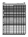
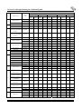
FG(R) 6.5H/A,
FG(R)7.5H/A Indoor unit parts breakdown
Quantity
No.
Code
Name
Fig No.
1
2
3
4
5
6
7
Cover board of air return
Lower cover plate parts
Water container parts
Air return port side plate assy
Motor FG150B
Fan motor (left type)
Fan mounting plate assy
9
10
11
12
01258614
01258612
01278612
01498609
15018612
15018603
01338631
01008501
01008628
01078603
01308678
02118504
01408628
Evaporator left bracket
Left side plate parts
Hook
Electric box assy
FGR7I.0000003
FGR7I.02000000
FGR7I.08000000
FGR7I.07000000
FGRD10I.01010008a
FGRD10I.03010003
FGR7I.03000000
FGR6I.09000000
FGR7I.09000000
FGRD10I.09010005
FGRD10I.04000000
FGRD10I.00000009
FGRD10I.12010000
13
02115001
Heating element locking parts 1
RFD12WA.1-7
14
01222401
Electric heating pipe fixing bar
(1252PA).0100001
15
46018501
Thermal protector assy
FGR7I.10000001
16
01498612
3900018710
390000451
3900018711
3900018717
30505002
Air outlet assy
8
Evaporator parts
FG(R6.5H/A)
FG(R)7.5H/A
1
1
1
1
1
1
1
1
/
1
1
4
1
3(used by heat
pump)
3(used by heat
pump)
1(used by heat
pump)
1
1
/
1
/
1
1(used by cooling
only type)
1
1
1
1
1
1
1
/
1
1
1
4
1
3(used by heat
pump)
3(used by heat
pump)
1(used by heat
pump)
1
/
1
/
1
1
Remote controllerzy502a
FGR7I.06010000
TY.13.04.03(10)
TY13.02.82(01)
TY.13.04.03(11)
TY.13.04.03(17)
30505.002MX
30294002
Display board Z4015
30294.002MX
30294001
Display board Z4035
30294.001MX
/
1(used by heat
pump)
30294401
Display board Z4415_M
30294.401MX
1(used by cooling
only type)
/
30294010
Display board Z4435_M
30294.010MX
/
21
01258651
Upper cover plate parts
FGR7I.01000000
22
32012402
Electric heater
(8052PA),01000003
23
01224255
Heating element bracket II
(7050L).01000003
24
01228632
Heating element bracket 1
FGRD10I.10010001
01228637
Heating element bracket 2
FGR7I.10010001
25
01228638
Heating element bracket 3
FGR7I.10010002
26
27
28
29
30
31
32
01308679
01078604
Right side plate parts
Evaporator right bracket
15018604
44010234
33010014
Fan motor(right type)
AC contactor GC8-30
Capacitor CBB61 8F/450V
FGRD10I.05000000
FGRD10I.09010006
/
FGRD10I.03010003
44010234
1
3(used by heat
pump)
6(used by heat
pump)
2(used by heat
pump)
1(used by heat
pump)
1(used by heat
pump)
1
1
1(used by heat
pump)
1
3(used by heat
pump)
6(used by heat
pump)
2(used by heat
pump)
1(used by heat
pump)
1(used by heat
pump)
1
1
1
1
1
1
1
1
43110168
43110209
Power transformer SC25A
Power transformer SC39
TY.11.01.12
TY.11.01.37
/
1
30224002
Mainboard Z4015
30224.002MX
1
/
1(used by cooling
only type)
17
18
19
Indoor ambient temperature sensor
Indoor pipe temperature sensor
20
33
30224001
Mainboard Z4035
30224.001MX
/
30224403
Mainboard 2 Z4415_M
30224.403MX
1(used by cooling
only type)
34
35
36
37
38
30224405
Mainboard 2 Z4435_M
30024.405MX
/
42011117
420111591
70410524
71010102
42011103
Six-position terminal board
Terminal board(3 positions)
Insulation spacer F
Electric wire holder
Terminal board 2-8
TY.00.57
TY.14.02.13(01)
TY.00.84a
LF7.5WB.06000001
TY.00.205
1
1
1
3
2
- 42 -
/
/
1(used by heat
pump)
/
1(used by heat
pump)
1
1
1
3
2
Explosive view and list
FG(R) 10H/A,
FG(R)12H/A FGD(R) 10H/A Indoor unit parts breakdown
Quantity
No.
Code
Name
Fig No.
1
01258602
Cover board of air return
2
01258603
3
4
5
15018612
Motor FG150B
FGRD10I.0101008a
1
1
1
6
15018603
Fan motor(left type)
FGRD10I.03010003
2
2
2
7
01338630
Fan mounting plate assy
FGRD10I.03010000
1
1
1
8
01008627
Evaporator parts
FGRD10I.09000000
1
1
1
9
01078603
Evaporator left bracket
FGRD10I.09010005
/
/
/
10
01308678
Left side plate parts
FGRD10I.04000000
1
1
1
FG(R)10H/A
FG(R)12H/A
FGRD10I.02010002
1
1
FG(R)10H/A
1
Lower cover plate parts
FGRD10I.02000000
1
1
1
01278603
Water container parts
FGRD10I.0800000
1
1
1
01498604
Air return port side plate assy
FGRD10I.0701000
1
1
1
11
02118504
Hook
FGRD10I.00000009
4
4
4
12
01408628
Electric box assy
FGRD10I.12010000
1
1
1
13
02115001
Heating element locking parts I
RFD12WA.1-7
3
3
3
14
01222401
Electric heating pipe fixing bar
(1252PA).01000001
3
3
3
15
46012402
Thermal protector assy
(1252PA).01030000
1
1
1
16
01498608
Air outlet side plate assy
FGRD10I.06000000
1
1
1
17
3900018710
Indoor ambient temperature sensor
TY.13.04.03(10)
1
1
1
18
3900018711
Indoor pipe temperature sensor
TY.13.04.03(11)
1
1
1
19
30505002
Remote controllerzy502a
30505.002MX
1
1
1
30294002
Display board Z4015
30294.002MX
1(used by cooling
only type)
1(used by cooling
only type)
1(used by cooling
only type)
30294001
Display board Z4035
30294.001MX
1(used by heat
pump)
1(used by heat
pump)
1(used by heat
pump)
01258607
Upper cover plate parts
FGRD10I.01000000
1
1
1
3(used by heat
pump)
/
20
21
32018614
Electric heater
FGRD10I.10000001
3(used by heat
pump)
32018612
Electric heater
FGRD10I.10000001
/
/
3(used by heat
pump)
01224255
Heating element locking parts II
(7050L).01000003
6(used by heat
pump)
6(used by heat
pump)
6(used by heat
pump)
01228632
Heating element bracket 1
FGRD10I.10010001
2(used by heat
pump)
2(used by heat
pump)
2(used by heat
pump)
01228633
Heating element bracket 2
FGRD10I.10010002
1(used by heat
pump)
1(used by heat
pump)
1(used by heat
pump)
25
01228634
Heating element bracket 3
FGRD10I.10010003
1(used by heat
pump)
1(used by heat
pump)
1(used by heat
pump)
26
01308679
Right side plate parts
FGRD10I.05000000
1
1
1
27
01078604
Evaporator right bracket
FGRD10I.09010006
1
1
1
28
15018613
Motor FG75B
FGRD10I.0100009a
1
1
1
29
15018604
Fan motor(right type)
FGRD10I.03010003
1
1
1
44010199
AC contactor LCIK0910M7
44010199
1
1
/
44010234
AC contactor GC8-30
/
/
1
31
33010014
Capacitor CBB61 8μF/450V
1
1
1
32
33010064
Capacitor CBB61 5μF/450V
QJ/GD.53.12
1
1
1
33
43110168
Power transformer SC25A
TY.11.01.12
1
1
1
1(used by cooling
only type)
1(used by cooling
only type)
22
23
24
30
30224002
Mainboard Z4015
30224.002MX
1(used by cooling
only type)
30224001
Mainboard Z4035
30224.001MX
1(used by heat
pump)
1(used by heat
pump)
1(used by heat
pump)
42011143
Nine-position terminal board
TY.14.01.76
1
1
1
42011143
Nine-position terminal board
TY.14.01.76
1
1
1
42011133
Eight-position terminal board
TY.14.01.66
1
1
1
36
70410524
Insulation spacer F
TY.00.84a
1
1
1
37
71010102
Electric wire holder
LF7.5WB.06000001
3
3
3
38
42011103
Terminal board 2-8
TY00.205
2
2
2
34
35
- 43 -
FG Series wind pipe blowing air-conditioning unit
FG(R) 6.5/A,
No.
Code
FG(R)7.5/A Indoor unit parts breakdown
Name
Quantity
Fig No.
FG(R)6.5/A
FG(R)7.5/A
1
01252463
Cover board of air return
KFR80PNA1A.02000002
1
1
2
01252461
Lower cover plate
KFR80PNA1A.02000001
1
1
3
01272458
Water container parts
KFR80PNA1A.08000000
1
1
4
01499064
Air return port side plate assy
FGR6AI.09010000
1
1
5
15012456
Motor FG90B
(7642P).03000003
1
1
6
15012454
Fan motor (left type) SYP-160/200J
KFR80PNA1A.03000002
2
1
7
01339060
Fan mounting plate assy
FGR6AI.03010000
1
1
8
01002463
Evaporator parts
(8042PA).1000000
1
1
1
9
01072483
Evaporator left bracket
KFR80PNA1A.12000000
1
10
01309057
Left side plate assy
FGR12AI.04010000
1
1
11
02112466
Hook
KFR80PNA1A.06000000
4
4
12
01408628
Electric box assy
FGRD10I.12010000
1
1
3(used by
cooling only
type)
3(used by heat
pump)
13
02115001
Heating element locking parts I
RFD12WA.1-7
3(used by
cooling only
type)
14
01222401
Electric heating pipe fixing bar
(1252PA).01000001
3(used by heat
pump)
15
46012402
Thermal protector assy
(1252PA).01030000
1
1
16
01492458
Air return port side plate assy
KFR80PNA1A.09000000
1
1
17
390000451
Indoor ambient temperature sensor
TY.1302.82(01)
1
1
18
3900018717
Indoor pipe temperature sensor
TY.13.04.03(17)
1
1
19
305050021
Remote controllerzy502a
30505.0021MX
1
1
30294401
Display board Z4415_M
30294.401MX
1(used by
cooling only
type)
1(used by
cooling only
type)
30294010
Display board Z4435_M
30294010MX
1(used by heat
pump)
1(used by heat
pump)
1252457
Upper cover plate parts
KFR80PNA1A.01000000
1
1
3(used by heat
pump)
20
21
22
32012402
Electric heater
(8052PA).01000003
3(used by heat
pump)
23
01224255
Heating element locking parts II
(7050L).01000003
6(used by heat
pump)
6(used by heat
pump)
24
01222407
Electric heating pipe upper mounting
rack
(8052PA).01010001
1(used by heat
pump)
1(used by heat
pump)
25
01222405
Electric heating pipe lower mounting
rack
(8052PA).10000002
1(used by heat
pump)
1(used by heat
pump)
26
01302471
Right side plate parts
(1242PA).05000000
1
1
27
01072482
Evaporator right bracket
KFR80PNA1A.11000000
1
1
1
1
28
/
29
15012458
Fan motor(right type)
30
44010234
AC contactor GC8-30
31
33010011
Capacitor CBB61 4μF/450V
43110209
Power transformer SC39
KFR80PNA1A.11000000
QJ/GD.53.12
32
33
1
1
1
1
/
TY.11.01.37
1
1
1(used by
cooling only
type)
30224403
Mainboard 2Z4415_M
30224.403MX
1((used by
cooling only
type)
30224405
Mainboard 2Z4435_M
30224.405MX
1(used by heat
pump)
1(used by heat
pump)
35
420111591
Terminal board(3 positions)
TY.14.02.13(01)
1
1
36
70410524
Insulation spacer F
TY.00.84a
1
1
37
71010102
Electric wire holder
LF7.5WB.06000001
3
3
38
42011103
Terminal board 2-8
TY.00.205
2
2
34
- 44 -
Explosive view and list
FG(R)10/A,
No.
Code
FG(R)12/A indoor unit parts breakdown
Name
Quantity
Fig No.
FG(R)10/A
FG(R)12/A
1
01252474
Cover board of air return
(1242PA)02000002
1
1
2
01259063
Lower cover plate
FG12AI 02000001
1
1
3
01272459
Water container parts
(1242PA)08000000
1
1
4
01499059
Air return port side plate assy
FGR12AI.09010000
1
1
5
15012456
Motor FG90B
(7642P).03000003
1
1
6
15012454
Fan motor (left type)
KFR80PNA1A.03000002
2
1
7
01339056
Fan mounting plate assy
FGR12AI.03010000
1
1
01002468
Evaporator parts
(1232PA).10000000
1
/
8
01032453
Evaporator parts
(1242PA).10000000
/
1
9
01072483
Evaporator left bracket
KFR80PNA1A.12000000
1
1
10
01309057
Left side plate assy
FGR12AI.04010000
1
1
11
02112466
Hook
KFR80PNA1A.06000000
4
4
12
01408628
Electric box assy
FGRD10I.12010000
1
1
3(used by cooling
only type)
13
02115001
Heating element locking parts I
RFD12WA.1-7
3(used by cooling
only type)
14
01222401
Electric heating pipe fixing bar
(1252PA).01000001
3(used by heat pump)
3(used by heat
pump)
15
46012402
Thermal protector assy
(1252PA).01030000
1(used by heat pump)
1(used by heat
pump)
16
01492463
Air return port side plate assy
(1242PA).09000000
1
1
17
390000198
Indoor ambient temperature sensor
TY.13.04.09
1
1
18
3900018717
Indoor pipe temperature sensor
TY.13.04.03(17)
1
1
19
305050021
Remote controllerzy502a
30505.0021MX
1
1
30294401
Display board Z4415_M
30294.401MX
1(used by cooling
only type)
1(used by cooling
only type)
30294010
Display board Z4435_M
30294010MX
1(used by heat pump)
1(used by heat
pump)
1259061
Upper cover plate parts
FGR12AI 01010000
1
1
20
21
22
32012401
Electric heater 1200W/220V
(1252PA).01000003
3(used by heat pump)
3(used by heat
pump)
23
01224255
Heating element locking parts II
(7050L).01000003
6(used by heat pump)
6(used by heat
pump)
24
01222404
Electric heating pipe upper mounting
rack
(8052PA).01010001
1(used by heat pump)
1(used by heat
pump)
25
01222402
Electric heating pipe lower mounting
rack
(8052PA).10000002
1(used by heat pump)
1(used by heat
pump)
26
01302471
Right side plate parts
(1242PA).05000000
1
1
27
01072482
Evaporator right bracket
KFR80PNA1A.11000000
1
1
28
15012457
Motor FG45B
(1242PA).05000000
29
15012458
Fan motor(right type)
KFR80PNA1A.03000002
1
1
30
44010199
AC contactor LC1K0910M7
31
33010011
Capacitor CBB61 4μF/450V
QJ/GD.53.12
32
33010026
Capacitor CBB61 2.5μF/450V
QJ/GD.53.12
1
1
33
43110209
Power transformer SC39
TY.11.01.37
1
1
30224405
Mainboard 2 Z4435_M
30224.403MX
1((used by cooling
only type)
1(used by cooling
only type)
30224403
Mainboard 2 Z4415_M
30224.405MX
1(used by heat pump)
1(used by heat
pump)
420111563
Terminal board(5 positions)
TY.14.02.13(03)
1
1
70410525
Insulation spacer D
TY.00.166
1
1
70410524
Insulation spacer F
TY.00.84a
/
/
37
71010102
Electric wire holder
LF7.5WB.06000001
2
2
38
42011103
Terminal board 2-8
TY.00.205
2
2
34
35
36
- 45 -
1
1
1
1
FG Series wind pipe blowing air-conditioning unit
4.2.2
Parts breakdown for outdoor unit as shown in Fig 4.2.2-1
Fig 4.2.2-1
- 46 -
Explosive view and list
FG(R)2.6 H/A
FG (R) 3.5H/A
FG (R) 5H/A Outdoor unit parts breakdown
Quantity
No.
Code
Name
Fig No.
FG(R)2.6H/A
FG(R)3.5H/A
FG(R)5H/A
KF35WF 08000002
1
1
1
1
22413431
Panel grid(module A )
2
20002041
Front panel
KA110W 09000001
1
1
1
3
11123404
Rear grill
KF35WF 07000001a
1
1
1
4
01253261
Top cover assy
KF35WF 10000000
1
1
1
01302000
Right side plate assy
KF35WF 09000000
1
1
/
5
6
7
01302001
Right side plate assy
KF35WF 09000000a
/
/
1
26233431
Big handle
KF35WF 11000001
1
1
1
01713413
Valve bracket assy
KF101W 05000000
1
/
/
01713039
Valve bracket assy
KF20WF 05010000
/
1
/
01713424
Valve bracket
KF35WF 05010001
/
/
1
01303324
Base plate assy
KF25WE 01000000b
/
1
1
01303008
Base plate assy
KA200W 01000000m
/
1
/
01205014
Base plate assy(Hitachi)
KG411W 01000000
10
76313102
Net cover pad
KF35WF 070000004a
1
1
1
11
10333412
Axial flow fan
KF35WF 02000002
1
1
1
01109057
Condenser parts
KGR2HAO 01000000
1
/
/
01109054
Condenser parts
KG3HAO 01000000
/
1
/
01103470
Condenser parts
KFR50WpK 03000000
/
/
1
01703069
Motor bracket
KFR25WA12F 02000001a
1
1
/
01703391
Motor bracket
KF35WF 02010001
/
/
01703067
Motor bracket
Kfr25wa12f 02000001
/
/
15013153
Motor FW30E
KF35WF 02000001
1
/
/
8
9
12
13
/
1(used by cooling
only type)
1(used by heat
pump)
14
15013039
Motor FW48C
Ka101W 00000002c
/
1
1
01239052
Separator assy
FGR5HAO 04010000
1
1
1
03029055
Four-way valve assy
FGR2HAO 14000000
/
/
03029054
Four-way valve assy
FGR5HAO 02010000
/
43005003
Four-way valve assy
KG411CW 10000000
/
/
00120078
Compressor RH174VHAC
1
/
/
17
00100131
Compressor C-RV222H1AA
/
1
/
07100025
Compressor SHW33TC4-U
/
/
1
18
07100145
Valve1/4”
TY.00.285B
1
1
1
07100145
Valve 3/8”
TY.01.53A
1
/
/
07100153
Valve 1/2”
TY.01.53B
/
1
1
3900012125
Sensor
TY.13.02 19(25)
1(used by heat
1(used by heat
1(used by heat
pump)
pump)
pump)
15
16
1(used by heat
pump)
1(used by heat
pump)
/
1(used by heat
pump)
19
20
- 47 -
FG Series wind pipe blowing air-conditioning unit
FG(R)2.6 H/A
FG (R) 6.5H/A
FG (R) 7.5H/A Outdoor unit parts breakdown
Quantity
No.
Code
Name
Fig No.
FG(R)6.5H/A
FG(R)6.5/A
FG(R)7.5H/A
FG(R)7.5/A
1
22265251
Face cover(apricot color)
LF7.5WB 10000001
1
1
1
1
2
01433031
Outer cover
KFR25×2WE.02000001a
1
1
1
1
3
01473028
Net cover
KFR25×2WE.06000001a
1
1
1
1
4
01255262
Top cover
LF7.5WB.09000001
1
1
1
1
5
01305002
Rear side plate
KF50W1B 00000001
1
1
1
1
6
26235253
Handle
LF7.5WB.00000005a
1
1
1
1
7
01715001
Valve bracket assy
KF501B 01010000
1
1
1
1
01205107
Base plate parts
KF60W1ED 10000000a
1
/
/
/
01205032
Base plate parts
KF601ED 10000000a(01)
/
1
/
/
01205264
Base plate parts
LF7.5WB.01010000(02)
/
/
1
1
9
01303023
Front side plate
KFR25×2WE.03000001
1
1
1
1
10
76315252
Net cover pad
LF7.5WB.00000010a
1
1
1
1
10335253
Axial flow fan
LF7.5WB 00000003
1
1
/
/
10335257
Axial flow fan
KFR60W1ED 00000008
/
/
1
1
01108503
Condenser parts
FGR6(O).01000000
1
1
/
/
01109058
Condenser parts
FGR7A(O).01000000
/
/
1
/
01105226
Condenser parts
KF76W1E.01000000
/
/
/
1
01703041
Motor bracket assy
KA110W.08000000(03)
1
1
/
/
01705103
Motor bracket assy
KF60W1ED.20000000
/
/
1
1
15013302
Motor FW68T
KFR120WtB.03000001
1
1
/
/
15015201
Motor LW80F
KF70W1EX.00000002
/
/
1
1
01233024
Middle separator assy
KFR25×2WE.05000000
1
1
1
1
03025002
Four-way valve assy
KFR501ED.05000000a
/
/
/
/
/
1( used by heat
1(used by heat
pump)
pump)
8
11
12
13
14
15
1( used by heat
pump)
1(used by
16
03029056
Four-way valve assy
FGR6AO.05010000
/
heat pump)
43005210
Four-way valve assy
KFR70W1EW.03000000
/
/
Compressor
00100140
1
1
/
/
/
/
1
1
SHV33YE6UG
17
Compressor
00100065
ZR34KH-PFJ-522
07105256
Small valve assy
LF7.5WB.13000000(01)
1
1
/
/
07105255
Small valve assy
LF7.5WB.13000000
/
/
1
1
071052521
Big valve assy
LF7.5WB.12000000(01)
1
1
/
/
07105251
Big valve assy
LF7.5WB.12000000
/
/
1
1/
20
3900012125
Sensor
TY.13.02.19(25)
/
/
1
1
21
3900012126
Sensor
TY.13.02.19(26)
1
1
18
19
- 48 -
1( used by heat
1(used by
pump)
heat pump)
Explosive view and list
FG(R) D10H./A
No.
Code
FG(R) 10H/A
Name
FG(R)10/A
FG(R)12H/A Outdoor unit parts breakdown
Quantity
Fig No.
FG(R)D10H/A
FG(R)10H/A
FG(R)10/A
FG(R)12H/A FG(R)12/A
1
22265251
Face cover
LF7.5WB 10000001
2
2
2
2
2
2
01435433
Outer cover
KFR120W1B.00000001
1
1
1
1
1
3
01475432
Net cover
KFR120W1B.00000002a
1
1
1
1
1
4
01255262
Top cover
KFR120W1B.09000001
1
1
1
1
1
5
01305434
Rear side plate
KFR120W1B.07000001
1
1
1
1
1
6
26235252
Handle
LF7.5WB.00000005
3
3
3
3
3
7
01715001
Valve bracket assy
KF50WB.01010000
1
1
1
1
1
01205011
Base plate assy
LF7.5WB.01010000(01)
1
/
/
/
/
01205264
Base plate assy
KFR120WB.01010000(02)
/
1
/
/
/
8
01205433
Base plate assy
KFR120W1E.11010000
/
/
1
/
/
01205250
Base plate assy
KF70W1B.03000000
/
/
/
1
1
9
01305431
Front side plate
KFR120W1B.06000001
1
1
1
1
1
10
76315252
Net cover pad
LF7.5WB.00000010a
1
1
1
1
1
11
10335253
Axial flow
fan
LF7.5WB.00000003
2
2
2
2
2
01108630
Condenser parts
FGRD10(O).01000000
1
/
/
/
/
01108054
Condenser parts
FGR10(O).01000000
/
1
/
/
/
01103456
Condenser parts
KFR100WpK.01000000
/
/
1
/
/
01108604
Condenser parts
FGR12(O)01000000
/
/
/
1
/
01103455
Condenser parts
KFR120WpK.01000000
/
/
/
/
1
12
13
01705432
Motor bracket
KFR120W1B.03000000
1
1
1
1
1
14
15015421
Motor LW68A
KFR120W1B.00000001
2
2
2
2
2
15
01235440
Separator assy
KFR120W1B.04000000
1
1
1
1
1
43008630
Four-way valve
parts
FGRD10(O).03000000
1(used by heat
pump)
/
/
/
/
43003453
Four-way valve
parts
KFR120WpK.03000000
/
1(used by heat
pump)
/
/
/
03025440
Four-way valve
parts
KFR120WLE.03000000a
/
/
1(used by heat
pump)
/
/
43003454
Four-way valve
parts
KFR120WLE.03000000a
/
/
/
1(used by
heat pump)
/
43009052
Four-way valve
parts
FGR12AO.03010000
/
/
/
/
1(used by
heat pump)
16
00100068
Compressor
1
/
/
/
/
17
00120043
Compressor
/
1
1
/
/
00100330
Compressor
/
/
/
1
1
18
07103701
Small valve assy
KF120WtB.01000001
1
1
1
1
1
19
07105435
Big valve assy
KFR120W1B.13000000
1
1
1
1
1
390001291
Outdoor ambient
temperature
sensor
TY.13.02.18(01)
1
1
/
1
/
3900012125
Outdoor ambient
temperature
sensor
TY.13.02.19(25)
1
1
/
1
/
3900012126
Outdoor ambient
temperature
sensor
TY.13.02.19(26)
/
/
/
/
1
390001211
Outdoor pipe
temperature
sensor
TY.13.02.19(01)
/
/
/
1
/
3900012126
Outdoor pipe
temperature
sensor
TY.13.02.19(26)
/
/
1
/
/
3900012129
Outdoor pipe
temperature
sensor
TY.13.02.19(29)
/
/
/
/
1
20
21
- 49 -
FG Series wind pipe blowing air-conditioning unit
4.1 Disassembly Procedures
4.2.1 Disassembly procedures for indoor unit
1)Disassemble electric box
Fastening
screw
electric box(4)
Screw off the fastening screws of the electric box
cover, remove the electric box cover(as shown in
Fig 4.2.1-1).
Loosen the power cable and the control wire on the
connection terminal, pull out the power cable and
the control wire.
Screw off the fastening screws of the electric box,
remove the electric box(as shown in Fig 4.2.1-2)
Fig 4.2.1-1
Fastening screw of electric box(4)
Fig 4.2.1-2
2)Disassembly of side plate of rear air return port
Screw off the fastening screw of the rear air return port,
take down the side plate of the rear air return port(as
shown in Fig 4.2.1-3)
Side plate of rear air
Fastening screw of rear
return port
air return port
- 50 -
of
Disassembly procedure
3)Disassembly of side plate of air supply port
Screw off the fastening screw of the air supply port, take
down the side plate of the air supply port (as shown in
Fig 4.2.1-4)
Fastening screw of air outlet
Air outlet
Fig 4.2.1-4
4) Disassembly of lower cover plate
Screw off the fastening screw of the lower cover plate,
take down the lower cover plate
(As shown in Fig 4.2.1-5)
Lower cover plate
Fixing bolt of lower
cover plate
Fig.4.2.1-5
5) Disassembly of right side plate
Screw off the bolts of the right side plate, and take off
the right side plate
(As shown in Fig 4.2.1-6)
Right side plate
Drainage pipe
Bolts of the right side plate
Fig.4.2.1-6
- 51 -
FG Series wind pipe blowing air-conditioning unit
Water-tray
6) Disassembly of water-tray
Take out the water-tray assy(As shown in Fig 4.2.1-7)
Fig 4.2.1-7
Fastening screw
7) Disassembly of left side plate
Screw off the fastening screw of the air port plate of left
side plate, take down the air port plate of the left side
plate (As shown in Fig 4.2.1-8)
Air port plate
Fig 4.2.1-8
Screw off the bolts of the left side plate, and take off the
left side plate
(As shown in Fig 4.2.1-9)
Bolts of the left side plate
Left side plate
Fig 4.2.1-
- 52 -
Disassembly procedure
Heating pipe
locking parts
Electric heater
8) Disassembly of electric heating pipe
Screw off the fixing bolt of the electric heating locking
parts.
Loosen the connection wire of the high temperature
protection assy, take down the electric heating pipe(As
shown in Fig 4.2.1-10)
Heat fuse
Temperature limiter
Fig 4.2.1-10
9) Disassemble evaporator
Evaporator
Screw off the bolts of the evaporator
Liquid Inlet Tube
Disconnect the connection between the pipe inlet and
outlet and other pipes.
(As shown in Fig 4.2.1-11)
Capillary Pipe
Fastening Screw
Air Discharge Pipe
Fig 4.2.1-11
10) Disassembly of evaporator supporter
Screw off the tapping screw of the evaporator bracket,
take away the evaporator bracket
(As shown in Fig 4.2.1-12)
Evaporator bracket
Fastening screw
Fig 4.2.1-12
- 53 -
FG Series wind pipe blowing air-conditioning unit
11) Disassembly of fan
Screw off the fastening bolts between the fan and the
motor.
Fan motor
Screw off the fastening screw of the fan and take down
the fan .
Fan mounting plate
(As shown in Fig 4.2.1-13)
Fan fastening screw
Fig 4.2.1-13
12) Disassembly of fan motor
Loosen the connection plug of the motor wire, lead the
motor wire through the wire hole.
Motor fixing bolt
Screw off the fixing bolt of the motor and take down the
motor
(As shown in Fig 4.2.1-14)
Motor
Fig 4.2.1-14
- 54 -
Disassembly procedure
4.2.2 Disassembly procedures of the outdoor unit
Front side plate
1)Disassembly of front side plate
Screw off the fastening screw of the front side plate(As
shown in Fig 4.2.2-1)
Handle
Grasp the handle and push the front side plate
downwards.
Fastening bolt
Fig 4.2.2-1
2) Disassembly of rear side plate
Loosen the power cable and the control on the
connection terminal and pull out the power cable and the
control wire.
Fastening bolt
Screw off the fastening screws of the electric box and
those of the rear side plate.
Grasp the handle and pull out the front side plate
upwards (as shown in Fig 4.2.2-2).
Fig 4.2.2-2
- 55 -
FG Series wind pipe blowing air-conditioning unit
3) Disassembly of electric box
Fastening screw of electric box
Screw off the fastening screw of the electric box, pull it
upwards by hand and disassemble the electric box.
(as shown in Fig 4.2.2-3)
Fig 4.2.2-3
4) Disassembly of the compressor
Air discharge pipe
Screw off the patchcord on the electric connector of the
compressor.
Compressor
Solder and open the air suction pipe and the air
discharge pipe of the compressor.
Soldering point 1
(as shown in Fig 4.2.2-4)
Soldering point 2
Screw off the fixing nut of the compressor and take out
the compressor.
Air suction pipe
Compressor fixing nut
Fig 4.2.2-4
5) Disassembly of four-way valve
Screw off the fastening screws on the four-way valve
which are used to fasten the electromagnetical coil.
Valve body
Take down the electromagnetic coil.
Unsolder the soldering points between the four-way
valve and other pipes.
Electromagnetic
coil
Take off the four-way valve. (As shown in Fig.4.2.2.5)
Note: To unsolder the soldering points, do not let flames
touch other parts. The valve body must be completely
wrapped by wet cloth to avoid damages caused by the high
temperature.
- 56 -
Solder joint(4)
Fig 4.2.2-5
Disassembly procedure
6) Disassembly of the capillary
Unsolder the two soldering points between the capillary
and other pipes.
Solder joint
Capillary
Take off the capillary.
(as shown in Fig 4.2.2-6)
7)Disassembly of the big valve gate
Screw off the 2 bolts that fasten the big valve gate
Big valve gate
Unsolder the soldering points between the big valve and
the air return pipe, take down the big valve (as shown
in Fig 4.2.2-7).
Note: To unsolder the soldering points, the valve body must
be completely wrapped by wet cloth to avoid damages caused
by the high temperature.
Bolt
8)Disassembly of the small valve gate
Screw off the 2 bolts fastening the small valve gate
Unsolder the soldering point between the small valve
and the air return pipe, take down the small valve (as
shown in Fig 4.2.2-8)
Small valve gate
Note: To unsolder the soldering points, do not let flames
touch other parts. The valve body must be completely
wrapped by wet cloth to avoid damages caused by the high
temperature.
Bolt
- 57 -
FG Series wind pipe blowing air-conditioning unit
9)Disassembly of axial flow fan
Face cover
Screw off the two tapping screws fastening the face
cover(as shown in Fig 4.2.2-9)
Pull out the face cover downwards(locks on the back of
the face cover).
Bolt
Fig 4.2.2-9
Screw off the spherical nut that fastens the axial flow fan,
take down the external teeth lock washer.
Axial flow
fan
Pull out the axial flow fan(as shown in Fig 4.2.2-10)
Spherical nut
Fig 4.2.2-10
Top cover
10) Disassembly of the top cover
Screw off the screws which fix the top cover around,
take off the top cover(As shown in Fig.4.2.2-11)
Top cover fixing nut
Fig 4.2.2-
- 58 -
Disassembly procedure
11) Disassembly of panel
Screw off the panel fixing bolt and take down the panel.
Bolt
(as shown in Fig 4.2.2-12)
Panel
12)Disassembly of motor and fan motor
Loosen the connection plug of the motor wire and lead
the motor wire through the wire hole.
Motor
bracket
Screw off the fixing bolt of the motor bracket and take
out the motor bracket.
Screw off the motor fixing bolt on the motor bracket,
then pull out the motor backwards.
Motor
fixing bolt
(as shown in Fig 4.2.2-13)
Fixing bolt of
motor bracket
- 59 -
FG Series wind pipe blowing air-conditioning unit
More than 20% of the air conditioner malfunctions are caused by the electrical installation. Therefore, the quality
of the electrical installation directly affects the application, or even affects whether the system can start up and
operate reliably. So enough attention must be paid to the electrical installation of the ducted type unit. Now the
structure of the electric box of the ducted type unit is introduced as follows:
Minboard
Tansformer
Fan motor capacitor
AC contactor
Pwer terminal block
Indoor electric box
Fan motor capacitor
Mainboard
AC contactor
Over current protector
Transformer
Inverse phase protector
2-8 Terminal board
4-position terminal
board
Outdoor unit electric box
- 60 -
Unit maintenance
4.3 Maintenance item
4.3.1 Cleaning the air filters
1) Do not disassemble the air filter when cleaning is carried out, otherwise malfunctions may occur.
2) When the application environment of the air conditioner is dusty, the air filter must be cleaned many times
(normally it is cleaned once every two weeks).
Note: Please pay attention to the following before you begin to clean the air conditioner:
a)
Cut off all the power before you touch any connection devices.
b) The air conditioner can not be cleaned until the unit is shut and power is cut off, otherwise there may be
electric shock or hurt.
c)
Do not use water to clean the air conditioner, otherwise there may be electric shock.
d) Special attention must be paid to the cleaning of the air conditioner and the stable and robust stand shall be
used.
4.3.2 Maintenance in usage season
1) Check whether there is any block at the air inlet and the air outlet of the indoor and outdoor units;
2) Check whether the grounding wire is sound and complete;
3) Check whether the wire connection is sound and complete;
4) Check whether there are any texts on the display of the wire controller after the power is on.
Note: If there is anything abnormal, please ask the after-sale service personnel to provide instructions.
4.3.3 Maintenance after usage season
1) When it is fine, operate the unit in the air supply mode for half a day to dry the inside of the unit;
2) If the air conditioner is not used for a long time, shut down the power to save energy. After the power is shut,
texts on the wire controller display will disappear.
- 61 -
FG Series wind pipe blowing air-conditioning unit
Section Two B series small ducted type unit
Chapter 1 Summary
1. 1,
Product summary
Gree’s B series small ducted type unit is the super-thin ducted type unit independently developed by the company
itself. The unit combines the advantages of the A series and meanwhile has the features of being convenient and
flexible in installation and maintenance. It has been accepted and favored by a large number of users. The
application of the new intelligent defrosting mode enables the unit to operate more efficiently and reliably. It may
be widely applied to various small supermarkets, chain stores, families with multiple living rooms, hotels,
restaurants, offices, meeting rooms and villa families.
Item
Zero static pressure unit
Cooling only
FG2.3/B
FG2.6/B
FG3.5/B
Heat pump
FGR2.3/B
FGR2.6/B
FG5/B
FGR3.5/B
FGR5/B
The current models of B series small ducted type units are in table 1. 1-1.
Table 1.1-1
FG
(
/B
Design No.: it stands for B series
Unit type: O is for outdoor unit; I is for indoor unit.
Frequency conversion system: P is for the frequency conversion system, the
fixed frequency system is not expressed
Excess pressure type: H stands for the multi-excess pressure, the common
excess pressure super-thin type is not expressed
Cooling capacity: Number×kW
Power supply type: D is for the single-phase, the three phase is not expressed.
Air conditioner type: R is for heat pump units; the cooling only units are not
expressed.
Product type: For the FG Series Ducted Air-conditioning Units.
1.2,
Unit model expression method and example
1.2. 1
Model expression method
1.2.2
Example:
FG6.5/B: It refers to the zero-static-pressure, air-duct-air-supply, cooling only and super-thin air conditioner unit
with the nominal cooling capacity of 6.5KW.
- 62 -
Outline drawing
1.3.
Unit outline drawing and combination example
1.3.1
Outline drawing
Outdoor unit
Indoor unit
- 63 -
FG Series wind pipe blowing air-conditioning unit
1.3.2
1.4.
Combination example
Unit working principle and system diagram(same as A series)
1.5. Unit installation space(same as A series)
- 64 -
Technical parameter
1.6 Product specification and technical parameter(see the following table )
Performance parameter table of super-thin ducted type unit (zero static pressure)
Model
item
Cooling only
FG2.3/B FG2.6/B
Heat pump
FG3.5/B
FG5/B
FG6.5/B
FGR2.3/B
Cooling capacity
W
2300
2600
3500
5000
6500
2300
HEATING capacity(heat
pump/heat conversion)
W
-
-
-
-
-
2550(500)
COOLING
A
3.7
4.2
5.7
8.9
10.5
3.7
4.2
heat pump/转热
A
-
-
-
-
-
4.6(2.3)
5.0(3.7)
Current
Startup current
Power
FGR6.5/B
6500
2800(500) 3700(800) 5600(1500) 7000(2100)
5.7
8.9
10.5
6.1(3.7) 8.54(6.82) 10.9(9.55)
19
21
31
49
56
19
21
31
49
56
820
840
1250
1800
2250
820
840
1250
1800
2250
heat pump/heat
conversion
W
-
-
-
-
-
800(500)
W
1000
1200
1850
2750
3000
920(500) 1217(800) 1849(1500) 2200(2109)
1300
1700
2300
3600
4300
1400
220V-50Hz
Compressor
Fully-closed rotation type
m5/h
indoor
dB(A)
outdoor
dB(A)
420
540
840
1400
420
540
840
36
38
42
46
36
38
42
46
51
55
56
56
59
0.73
0.94
1.15
1.50
2.34
Cooling 剂 Name
51
55
56
56
59
0.73
0.94
1.15
1.5
2.34
R22
Filling amount of cooling agent (kg)
Outdoor
unit
5000
A
Air quantity
Indoor unit
3500
W
Power supply
Connection
pipe
2600
Cooling
Max. Power
noise
FGR2.6/B FGR3.5/B FGR5/B
Diameter of
liquid pipe
mm
φ6
φ6
φ9.52
φ6
φ6
φ9.52
Diameter of gas
pipe
mm
φ9.52
φ12
φ16
φ9.52
φ12
φ16
Width
mm
1007
1367
1607
1007
1367
1637
Depth
mm
510
510
510
510
510
510
Height
mm
Net weight
kg
Air outlet
Length mm
Dimension
Width mm
185
20
20
185
22
30
20
22
30
642
922
1242
642
20
922
1242
108
108
108
108
108
108
Width
mm
660
760
950
660
760
950
Depth
mm
250
250
412
250
250
412
Height
mm
430
530
700
430
530
700
Net weight
kg
25
32
59
25
32
59
Water drainage pipe(outer
diameter×measured
thickness)
mm
G3/4”
Note:1. The cooling only unit does not have the auxiliary electric heater. Only the heat pump unit had the
auxiliary electric heater.
2. The noise is measured under the half-silencing indoor condition. In actual operation, due to the change
of environment, the noise will be slightly louder.
3. The specifications and parameters will change due to product improvement. The specific parameters
shall refer to those on the nameplate of the unit.
4. The above unit model will change due to product improvement and production management
requirements. The specific models shall refer to those that leave the factory.
5. This series of units do not apply to air duct connection. The air duct connection will affect the normal
usage of the unit.
- 65 -
FG Series wind pipe blowing air-conditioning unit
Chapter 2 Electricity and control
2.1
Light current
2.1.1
circuit diagram
FGR2.3/B(0) circuit diagram
FG2.3/(B0) circuit diagram
- 66 -
Circuit diagram
FG3.5/B(0)
circuit diagram
FGR3.5/B(0)
circuit diagram
- 67 -
FG Series wind pipe blowing air-conditioning unit
FG5/B (0)
circuit diagram
FGR5/B(0)
circuit diagram
- 68 -
Circuit diagram
FG6.5/B (0)
circuit diagram
FGR6.5/B (0)
circuit diagram
- 69 -
FG Series wind pipe blowing air-conditioning unit
FG2.3/B (I); FG2.6/B (I); FG3.5/B (3.5) circuit diagram
FGR2.3/B (I); FGR2/6/B(I); FGR3.5/B(I) circuit diagram
- 70 -
Circuit diagram
FG5/B (I)
FGR5/B (I)
circuit diagram
circuit diagram
- 71 -
FG Series wind pipe blowing air-conditioning unit
FG6.5/B (I)
circuit diagram
FGR6.5/B (I)
circuit diagram
- 72 -
Circuit diagram
2.1.2
List of wiring
Please note: The length of all signal wires and power cables of the super-thin ducted type unit must be within 15
meters.
FGR 6.5/B
FG 6.5/B
indoort
unit
outdoort
unit
outdoort
unit
indoort
unit
①Power connection cord 3×2.5mm
①Power connection cord 3×2.5mm
②Power connection cord 6×2.5mm
②Power connection cord 4×2.5mm
indoort
unit
outdoort
unit
outdoort
unit
indoort
unit
①Power connection cord 3×2.5mm
①Power connection cord 3×2.5mm
②Power connection cord 2×2.5mm
②Power connection cord 3×2.5mm
③Power connection cord 3×2.5mm
outdoort
unit
indoort
unit
outdoort
unit
indoort
unit
①Power connection cord 3×2.5mm
①Power connection cord 3×2.5mm
②Power connection cord 2×2.5mm
②Power connection cord 2×2.5mm
③Power connection cord 4×2.5mm
③Power connection cord 4×2.5mm
- 73 -
FG Series wind pipe blowing air-conditioning unit
2.2
Light current
2.2.1
1.
Operation mode
Temperature parameter
Indoor ambient temperature T amb
Outdoor ambient temperature T amb
Evaporator middle temperature T eva
2.
Basic function
After the power is on, no matter when compressor is started, the time span between the startups cannot be less
than 3 minutes. When it is powered for the first time, the compressor does not have the time delay of 3 minutes.
Once the compressor starts up, it will not shut down due to the temperature change within 6 minutes.
2.1
COOL mode
2.1.1 Cooling condition and process
If T amb>T set, COOL mode will act, compressor and external fan will run, the indoor fan will run at the set
speed.
If T amb<T set, the unit will stop, compressor and external fan will stop, the indoor fan will run at the set speed.
If T amb=T set, the compressor and external fan will keep running in the old mode, the indoor fan will run at the
set speed.
The setting temp. range is 16℃~30℃.
2.1.2 Antifreezing Protection
When the antifreezing protection is detected, the compressor and external fan will stop, the indoor fan will run in
the old mode and the LCD displays E2. When antifreezing protection is eliminated and the compressor has
stopped for 3min, the whole unit will be put into the normal operation.
2.2
dry mode
If T amb>T set, the cooling and drying mode will act, compressor and external fan will run, indoor fan will run at
low speed
If T set =T amb, after the external fan and compressor running for 6 mins, it will stop about 4 mins, The processes
are shown as the above cycle. The indoor fan will run at the low speed.
If T amb<T set, the compressor and the external fan will stop.
The setting temp range is :16℃~30℃.
During the period, the antifreezing protection is treated as the cooling mode.
2.3
HEAT mode
2.3.1 Conditions and processes of heating
If T amb <T set, the heating operation will begin and the change valve, the external fan and the compressor are
respectively powered and put into operation. The indoor fan operates based on the set air speed and the cool air
condition.
If T amb=T set, the compressor, the external fan and the reversing valve will keep running in the old mode. The
indoor fan will run at the set speed and in the anti-cold-air condition.
If T amb>T set, the compressor will stop, after 15 seconds the external fan will stop, and the reversing valve will
keep working, the indoor fan will blow, after 60secs it will stop.
The setting temp. range is 16℃~30℃
- 74 -
Control logic
2.3.2 Anti-cool-air operation protection
When the compressor restarts after it stops or when the defrosting ends, the internal fan will begin to run after the
compressor runs for some time. If the compressor does not start up, the internl fan will stop operation.
2.4
Auto Defrosting
2.4.1 Conditions and processes of defrosting
After the heating operation, when the frost of the condenser is detected, the system enters the defrosting status. At
this time, the four-way valve, the external fan and the auxiliary electric heating stop operation. The compressor
performs the forced operation and the internal fan operates based on the anti-cool-air condition. When it is
detected that he frost on the condenser has been removed, the four-way valve and the external fan begin to operate
and then the internal fan begin to operate.
The first defrosting time when the power is on is 9 minutes. Later, the defrosting time will be adjusted based on
the frosting condition on the condenser. If there is much frost, the defrosting time is long. If there is not much frost,
then the defrosting time is short. When it is detected that the defrosting has ended, quit the defrosting mode.
2.5
SWING mode
The internal fan will run at the set air speed and there are several air speeds to be selected:
2.6
Auto mode
In this mode, the system can select the mode automatically according to the ambient temperature
3.
Other control
3.1
Timing Control.
TIMER OFF: Set the timer for turning off function when the unit is turned on, the PCB will act in the set
mode ,when it is time to turn off, the unit will be switched off.
TIMER ON: The unit is stopped when the timer for turning on acts. When it is time to turn on, the PCB will act in
the set mode.
3.2
Protection measure
3.2.1 High pressure protection
When the high pressure is detected, all the loads of the system are closed and E1 is displayed. After the ON/OFF
button is closed, the sound alarm is removed. Press the ON/OFF button to resume the operation.
3.2.2 Low pressure protection
When the low pressure is detected, all the loads of the system are closed. After the low pressure is eliminated, it
automatically resumes the operation. If there 3 consecutive low pressure protection, E3 is displayed and the
system can not automatically resume. After the ON/OFF button is pressed to shut down the unit, the sound alarm
is removed. Press the ON/OFF button again to resume the operation.
3.2.3 Indoor antifreezing protection
When the antifreezing protection is detected, the compressor and external fan will stop, the indoor fan will run in
the old mode and the LCD displays E2. When antifreezing protection is eliminated and the compressor has
stopped for 3min, the whole unit will be put into the normal operation.
3.2.4 Indoor super-high temperature protection
In the heating operation, when it is detected that the temperature of the evaporator is too high, the external fan will
stop operation. When the pipe temperature of the evaporator is normal, the external fan will resume operation.
3.2.5 Indoor environmental sensor protection
- 75 -
FG Series wind pipe blowing air-conditioning unit
If there is any open circuit or short circuit for the indoor environmental sensor, all the loads will be shut in the
cooling, dry and heating modes and “F0”will be displayed. The default indoor ambient temperature is 24℃. After
the malfunction is eliminated, the unit will automatically resume the operation and clear the malfunction code. In
the air supply mode, only the malfunction code is displayed and the internal fan operates normally. After the
malfunction is cleared, the malfunction code disappears.
3.2.6 Evaporator sensor protection
If there is any open circuit or short circuit for the evaporator temperature sensor,“F1”will be displayed. After the
malfunction is eliminated, the unit will automatically resume the operation and clear the malfunction code. In the
air supply mode, only the malfunction code is displayed and the internal fan operates normally. After the
malfunction is cleared, the malfunction code disappears.
3.2.7 Outdoor environmental sensor protection
If there is any open circuit or short circuit for the outdoor environmental sensor, all the loads will be shut only in
the heating mode and “F3” will be displayed. After the malfunction is eliminated, the unit will automatically
resume the operation and clear the malfunction code. In the air supply mode, only the malfunction code is
displayed and the internal fan operates normally. After the malfunction is cleared, the malfunction code
disappears.
3.3
Sleep function
In heating, press the button SLEEP, after 1 hour the set temperature drops by 1℃. After 2 hours the set
temperature drops by 2℃. Afterwards, this temperature is kept and the sleep sign is cleared.
In cooling, press the button SLEEP, after 1 hour the set temperature rises by 1℃. After 2 hours the set temperature
rises by 2℃. Afterwards, this temperature is kept and the sleep sign is cleared.
3.4
Test function
In the power-off status, press the temperature selection button (TEMP▲) to enter the heating status. The
compressor is on, the four-way valve is on, the internal fan runs at high speed and after the operation for 5 minutes,
the unit automatically shuts down. You may also press the ON/OFF button to stop the test.
In the power-off status, press the temperature selection button (TEMP▼) to enter the cooling status. The
compressor is on, the four-way valve is on, the internal fan runs at high speed after the operation for 5 minutes,
the unit automatically shuts down. You may also press the ON/OFF button to stop the test.
- 76 -
Manual controller
2.2.2
Description and usage method of manual controller
Note!
Do not install the wire controller at the position where there is water leakage.
Avoid knocking, throwing and frequent disassembly and installation of the wire controller.
Mode
Test
Fan speed
Environment
Auto
Fan speed
Setting
Auto
Sleep
Defrosting
Hour
Timing
On/off
Integral parts of wire controller
1
2
Display board identification code(the cooling only unit is
FG-05 and the cooling and heating unit is FG-06)
Mode display(cooling, dry
, air supply
, heating
,
automatic
)
9
Remote controll receiver
10
MODE button
3
Ambient temperature display
11
4
Sleep display
12
5
6
7
8
Air speed display(automatic, high speed, middle speed, low
speed)
Set temperature display
Defrosting status display
Timing display
- 77 -
13
14
15
16
Set temperature increase
button
Set temperature decrease
button
Fan speed button
Sleep button
Timing button
ON/OFF button
FG Series wind pipe blowing air-conditioning unit
1)
ON/OFF(Fig 2)
Press the button, the unit will start working
Repress the On/Off button, the unit stops working.
Mode
Environment
Fan
speed
Sleep
Timing
On/off
2) Fan control(Fig 3)〔The content shown in the figure
are the relevant display areas and are as follows〕
Fig 2
Press the fan control button once and the fan speed
will change in the order of:
→low speed→middle speed→high speed→automatic→
In the dry mode: The fan speed will be automatically
set to be the low speed.
Temperature adjustment (Fig 4)
Press the temperature adjustment button,
▲: To set the increase of the temperature
▼: To set the decrease of the temperature.
(Press this button once and the temperature will
increase or decrease by 1℃.)
The temperature set range in different modes:
HEAT——16℃~30℃
COOL——16℃~30℃
DRY ——16℃~30℃
- 78 -
Manual controller
4) Sleep function setup(Fig 5)
In COOL and DRY mode, press the SLEEP mode, the
setting temp. will be increased 1℃ in the first hour,
and it will be increased 2℃ in the second hour. Indoor
fan will run at the low speed, then the unit will run
accord to the setting temperature.
In HEAT mode, setting the SLEEP mode, the setting
temp. will be decreased 1℃ in the first hour, it will be
decreased 2℃ in the second hour. then the unit will
run accord to the setting temperature.
There is no SLEEP function in FAN mode.
Mode
Fan
speed
Sleep
Timing
On/off
5) The running mode setting (Fig.6)
Fig 5
When pressing MODE button each time, the mode
will be changed as following:
→COOL→DRY→FAN→HEAT→AUTO
Mode
At “COOL” mode, the COOL display
will be light
on, the temperature of setting should be lower than the
room temperature. If the setting temperature is higher
than the room sensor, the unit will not run at cool
mode operation.
At “DRY” mode, the DRY display will be light on.
Fan motor will run at low fan speed in the definite
temperature range. The dehumidifying effect of this
mode is better than that in COOL mode and more
energy saving.
Auto
Defrosting
Fan
speed
Sleep
Timing
On/off
Fig 6
At “HEAT” mode, the HEAT display will be light on. The temperature should be set higher than the room
temperature; If the setting temperature is lower than the room temperature, the unit will not run at HEAT mode
operation.
A t”FAN” mode, the FAN display
will light on. The room temperature is displayed on the LCD of the
controller.
In the automatic mode, the automatic display ”automatic” will light on. At this time, the entire unit will select
the mode automatically based on the indoor ambient temperature. In cooling, the temperature is automatically
set to be 26℃. In the dry mode, the temperature is automatically set to be 24℃. In heating, the temperature is
automatically set to be 20℃.
Note: The automatic heating mode of the cooling only unit is replaced by the automatic air supply mode.
In heating, when the outdoor temperature is low and the humidity is high, the outdoor unit will frost and lead
to the low heating efficiency. In this case, the controller will automatically begin the defrosting circle and
display ”defrosting”.
Note: The cooling only unit does not have the heating mode.
- 79 -
FG Series wind pipe blowing air-conditioning unit
6) timing setup(Fig 7)
In the power-off mode, the startup time can be set. In the
power-on mode, the shutdown time can be set. Press the
timing button once and the set time increases by 0.5 hour.
Keep pressing the timing button and the set time increases
rapidly by 0.5 hour. When the time is set to be 24 hours,
press the timing button again to eliminate the timing(the
remote controller may also be used to eliminate the
timing)
The set range is 0.5~24 hours.
Mode
Fan
speed
Sleep
Timing
On/off
7)
When there is malfunction in the system, the
malfunction code will be displayed on the wire
controller. As shown in Fig 8, the indoor ambient
temperature sensor malfunction is displayed.
Meanings of the malfunction codes are as follows:
Malfunction Code
E1
E2
E3
F0
F1
F3
EH
Fig 7
Mode
Malfunction
Compressor high pressure
protection
Indoor Anti-freeze protection
Compressor low pressure
protection
Indoor environment sensor
malfunction
Evaporator sensor malfunction
Outdoor environment sensor
malfunction
Malfunction of auxiliary electric
heating
Fan
speed
Sleep
Timing
On/off
Fig 8
If the wire controller displays the malfunction, the unit may be shut down to stop the malfunction display and the
professional personnel are to be asked to eliminate the malfunction.
8) Power down memory function:
When the air conditioner is in the operation mode and the power is cut off, the controller will memorize the last
ON/OFF mode, the air speed, the set temperature and the timing operation status.
Note!
When there is a ”EH” malfunction, please immediately cut off the unit power and ask the
professional personnel for repair!
- 80 -
Manual controller
Names and functions of each part of the remote controller
For the air-duct indoor unit, the remote controller is optional.
NOTE:
Be sure that there are no obstructions.
The reception distance of the signal of the remote controller may reach about 10 meters.
Do not drop or throw the remote controller.
Avoid any liquid flowing into the remote controller.
Do not place the remote controller in a location exposed to direct sunlight or extra heat.
Air speed button
Press the button once, and the
air speed changes in the order
of:
Swing
Fan speed
Auto Fan speed
Automatic
air speed
air speed
operation
Auto
TEMP. button
Press the set temperature once
and it rises by 1 degree. Press
the set temperature once and it
drops by 1 degree.
In the mode, the room
temperature is randomly
adjusted between 16℃~30℃.
In the
mode, 16℃~30℃.
In the
mode, 16℃~30℃.
In the
mode, 16℃~30℃.
air
exchange
Negative
ion
Swing Dry Light save Power
Timing
switch
Hour
COOL mode
DRY mode
FAN mode
HEAT mode
ON/OFF button
Press this button, the unit
will start, press it once more,
the unit will stop, the timing
mode will be canceled at the
same time.
Mode selection button
Press this button to change the
operation mode in order of.
Mode
ON/OFF
(Note: The cooling only unit
does not have the
mode.)
- 81 -
FG Series wind pipe blowing air-conditioning unit
Names and function of remote controller(Remove the cover)
NOTE!
This model is a general-purpose remote controller, which can be applied to varieties of air conditioning
systems (various types and performances). No descriptions will be made on the functions and buttons that
are not applied in this air conditioning system.
Liquid crystal displayer
It shows all set contents.
Swing
Fan speed
Auto Fan speed
Operation
Auto
Air
exchange
Negative
ion
SLEEP button
Press this button once, the unit will go into the
sleep mode. Press the button once again, the
unit will quit the sleep mode.
Swing Dry Light save Power
Timing
switch
During the cooling and dehumidification
operations after the operations in the sleeping
mode, the set temperature will rise by 1~2℃
in a certain period of time, and the unit will
then operate under the condition of the set
temperature. During heating operation after
the operations in the sleeping mode, the set
temperature will drop by1~2℃ in a certain
period of time, and the unit will then operate
under the condition of the set temperature.
Hour
Swing
Air
exchange
Light
Dry
看不清楚
Mode
ON/OFF
Temperature /Timing button
When the unit is operating, press the “+” button once
and the temperature will go up by 1℃, and press the
“-” button once and the temperature will go down
by 1℃. The room temperature can be adjusted at
user’s discretion within the range of 16-30℃.
When the unit is in the On/Off mode, press the
“Timing” button will set the time for the turning off
or on of the unit. Press the “+” button, the timing will
be increased by 0.5 hour, press the “-”, the timing
will be decreased by 0.5 hour. After adjustments,
press the “Timing” button once again to transmit the
setting. Press the “Delete” button will cancel the time
setting.
- 82 -
Manual controller
Guide to operational controls
General steps:
1. After connecting to the power supply, press the ON/OFF button and the air conditioner unit is ready for
operation.
2. Press the MODE button to select the needed operational mode.
3. Set the fan speed by pressing the FAN button.
4. Press +/- button to select the needed temperature.
Optional steps:
5. Press the SLEEP mode button to set the unit in the sleeping mode.
6. Press the TIMER button and press the +/- button as well to set the desired operation time.
7. Press the ON/OFF button again, the air conditioner unit stops operation. The air conditioner supplies the
remaining coldness or heat for 20~70 seconds.
NOTE: When the selected operational mode of the indoor units contradicts the operational mode of the outdoor
unit, the fault alarming light of the indoor unit will flash in 1 second and the indoor unit will stop operating. In this
case, you may shift the operational mode of the indoor unit to the operational mode not contradictory to that of the
outdoor unit; and the unit will restore its normal operation. The cooling mode and the dehumidification mode are
not contradictory to each other. The air delivery mode is not conflicting to any other modes.
Installation of batteries into the remote controller
The remote controller uses two NO.7 alkali batteries
1. Slide downward the back cover of the remote controller and take out the used batteries, and then replace with
two new ones (in correct polarities).
2. Close the back cover of the remote controller.
1. After batteries are installed, the
screen will display figures and
letter codes of all functions. After
10 seconds the operation can
begin.
2. The lifespan of the battery is about
one year.
① Open the back cover
③ Close the back cover
3. Please do not mix the new and old
batteries of different types in the
application.
4. Please take out the batteries when
they are not used for a long time in
order to avoid malfunctions caused
by liquid leakage.
5. The remote controller shall be more
than one meter away from TV or
audio equipments.
6.
Reset button
The operation of the remote
controller shall be within the
reception area(the reception range
is 10 meters).
7. In case of the replacement of
batteries, etc, and the remote
controller is unable to control,
please take down the back cover
and press the ”ACL(resume)”
button to resume it to normal.
② Place two NO. 7 batteries (accessory).
- 83 -
FG Series wind pipe blowing air-conditioning unit
Chapter 3 Operation debugging and malfunction diagnosis
3.1
Check list of unit operation conditions and check items
Refer to check items of A series
3.2
List of parameter changes of unit operation
Refer to the list of parameter changes of A series
Malfunction
The air conditioner can not start up.
The air conditioner operates but soon
stops.
The cooling effect is bad.
The heating effect is bad.
In heating, the internal fan does not
start up.
3.3
Possible cause
1. Power is not on.
2. The air conditioner has electric leakage and
causes the switch tripping.
3. The wire voltage is too low.
4. The working button is closed
5. The control circuit has malfunction.
1. There are obstacles ahead of the condenser.
2. The control circuit is abnormal.
3. When the outdoor ambient temperature is
higher than 43 ℃ , the cooling operation
begins.
1.The air strainer has dirt or is blocked.
2.There is heating source in the room or there are
too many people
3.Doors or windows are opened.
4.There is obstacle at the air inlets and outlets.
5. The set temperature is too high and causes the
secondary refrigerant leakage
6. The performance of the room temperature
sensor becomes bad.
1. The air strainer has dirt or is blocked.
2. Doors or windows are not tightly closed.
3. The set room temperature is too low.
4.Leakage of cooling agent
5.The outdoor ambient temperature is lower than
-5℃
6. The control wire is abnormal.
1. The installation position of the pipe
temperature sensor is not appropriate.
2. The pipe temperature sensor is not properly
inserted.
3. The wire connection of the pipe temperature
sensor is broken.
4. Leakage of capacitor
List of malfunction analysis
Note: If the above checks and treatments are carried out and the conditioner still can not operate normally, please
stop the operation of the air conditioner immediately and contact the local maintenance office and ask the
professional maintenance personnel to repair it.
- 84 -
Malfunction analysis
3.4 Check list of malfunction code
Malfunction Code
Malfunction
E1
Compressor high pressure protection
E2
Indoor Anti-freeze protection
E3
Compressor low pressure protection
FO
Indoor environment sensor malfunction
F1
Evaporator sensor malfunction
F3
Outdoor environment sensor malfunction
EH
Malfunction of auxiliary electric heating
If the wire controller displays the malfunction, the unit may be shut down to stop the malfunction display and the
professional personnel are to be asked to eliminate the malfunction.
- 85 -
FG Series wind pipe blowing air-conditioning unit
Chapter 4 Care and Maintenance
4.1
Explosive view and spare parts list
1.1.1
Explosive view and spare parts list of indoor unit
4.1.1 Explosive view and spare parts list of indoor unit
- 86 -
Explosive view and list
No.
Material name
1
Upper cover plate
2
Left terminal plate 2
3
Electric heater
4
Evaporator assy(1.6.
water)
5
Sensor
6
Liquid distribution pipe
assy
Liquid inlet pipe assy
7
Gas collector assy
8
Thermal protector assy
9
Fixing plate of pipe clamp
10
Sealing plate
Connection wires between
plates(14 cores)
Mainboard 1 Z4735
11
12
Quantity
Material Code
01258766
01258763
01258765
01498767
320120051
32012005
3200187611
32018761
01039063
01039068
01039073
01008784
3900018717
03239114
03239121
03239144
03239117
03639092
03639097
03639104
03638777
46012405
017990583
17990582
017990584
01799058
01499082
FG(R) 2.3-B(I)
1
-
-
1
1
-
-
-
1
-
-
-
1
1
-
-
-
1
-
-
-
1
1
-
-
-
-
FG(R) 2.6-B (I)
1
-
-
1
1
-
-
-
1
-
-
-
1
1
-
-
-
1
-
-
-
1
1
-
-
-
-
FG(R) 3.5-B(I)
1
-
-
1
-
1
-
-
-
1
-
-
1
-
1
-
-
-
1
-
-
1
-
1
-
-
-
FG 5-B (I)
-
1
-
1
-
-
1
-
-
-
1
-
1
-
-
1
-
-
-
1
-
1
-
-
1
-
-
FG 6.5-B (I)
-
-
1
1
-
-
-
1
-
-
-
1
1
-
-
-
1
-
-
-
1
1
-
-
-
1
-
400102542
1
1
1
1
1
30224701
1
1
1
1
1
Capacitor CBB61
1.5uf-450V
33010020
1
1
1
-
-
Capacitor CBB61
4.5uf-450V
33010012
-
-
-
1
1
44010246
1
1
1
1
1
43110226
1
1
1
1
1
30294701
1
1
1
1
1
30294702
1
1
1
1
1
01419080
01419085
01498780
01218767
01218710
01218766
01708763
15018323
15019524
22202031
10312401
22202032
01338794
01338790
01338793
01218767
01218710
01218766
1
1
1
1
-
-
1
1
-
2
2
2
1
-
-
1
-
-
1
1
1
1
-
-
1
1
-
2
2
2
1
-
-
1
-
-
1
1
1
1
-
-
1
1
-
2
2
2
1
-
-
1
-
-
1
1
1
-
1
-
1
-
1
3
3
3
-
1
-
1
-
1
1
1
-
-
1
1
-
1
4
4
4
-
-
1
-
-
1
01498776
1
1
1
1
1
13
17
18
19
AC contactor
(GC8-30-D10)
Power supply transformer
48*26F
Display board Z4735
(heat pump)
Display board Z4715
(cooling only)
Electric box
Electric box cover
Left terminal plate 1
20
Base plate
21
23
24
25
Bracket (95)
Motor FG20D
Motor PG40E
Rear spiral case
Centrifugal fan
Front spiral case
26
Fan mounting plate
27
Base plate
28
Right terminal plate
14
15
16
22
- 87 -
FG Series wind pipe blowing air-conditioning unit
4.1.2
Explosive view and spare parts list of outdoor unit
- 88 -
Explosive view and list
Quantity
No.
1
2
Material name
Material Code
FG(R)2.3-B(0)
FG(R)2.6-B(0)
FG(R)3.5-B(0)
FG 5-B(0)
FG 6.5-B(0)
22263002
22413431
heat
pump
1
-
cooling
only
1
-
heat
pump
-
1
cooling
only
-
1
heat
pump
-
1
cooling
only
-
1
heat
pump
-
1
cooling
only
-
1
heat
pump
-
-
cooling
only
-
-
22265251
-
-
-
-
-
-
-
-
1
1
01533013
01533011
01433031
10333002
01703069
01703067
01703027
15013156
15013067
15013066
15013039
15013302
01703029
01703069
01703067
01703027
011032532
011032561
011090571
011090561
011090551
011090541
011031694
011037533
011034583
011034594
01253026
01253442
01255261
11123201
01473030
01473028
1
-
-
1
-
-
-
1
-
-
-
-
1
-
-
-
1
-
-
-
-
-
-
-
-
-
1
-
-
1
-
-
1
-
-
1
-
-
-
1
-
-
-
-
1
-
-
-
-
1
-
-
-
-
-
-
-
-
1
-
-
1
-
-
-
1
-
-
1
-
-
-
1
-
-
-
-
1
-
-
-
-
1
-
-
-
-
-
-
-
-
1
-
-
1
-
-
1
-
-
1
-
-
-
1
-
-
-
-
1
-
-
-
-
-
1
-
-
-
-
-
-
-
1
-
-
1
-
-
1
-
-
1
-
-
-
-
1
-
-
-
1
-
-
-
-
-
-
1
-
-
-
-
-
-
1
-
-
1
-
-
1
-
-
1
-
-
-
-
1
-
-
-
1
-
-
-
-
-
-
-
1
-
-
-
-
-
1
-
-
1
-
-
1
-
-
-
1
-
-
-
-
1
-
-
-
1
-
-
-
-
-
-
-
1
-
-
-
-
1
-
-
1
-
-
1
-
-
-
1
-
-
-
-
1
-
-
-
1
-
-
-
-
-
-
-
-
1
-
-
-
1
-
-
1
-
-
-
1
-
-
-
1
-
-
-
-
1
-
-
-
1
-
-
-
-
-
-
-
-
1
-
-
-
1
-
-
-
1
-
-
-
1
-
-
-
-
1
-
-
-
1
-
-
-
-
-
-
-
-
-
1
-
-
1
-
1
1
Capacitor CBB65
20uf/450V
33010044
1
1
-
-
-
-
-
-
-
-
Capacitor CBB65
25uf/450V
33000017
-
-
1
1
-
-
-
-
-
-
Capacitor CBB65
30uf/450V
33000018
-
-
-
-
1
1
-
-
-
-
Capacitor CBB65
50uf/440V
33000001
-
-
-
-
-
-
1
1
1
1
Capacitor CBB61
1.5uf/450V
330010020
1
1
-
-
-
-
-
-
-
-
Capacitor CBB61
2.5uf/450V
33010026
-
-
1
1
-
-
-
-
-
-
Capacitor CBB61
3uf/450V
33010027
-
-
-
-
1
1
1
1
-
-
Capacitor CBB61
3.5uf/450V
33010010
1
1
-
-
-
-
-
-
1
1
Face cover
Panel bar rack
Face cover(apricot
color)
Panel
Outer cover
3
Electric heater
4
Motor FW20F
Motor FW30K
Motor FW48G
Motor FW48C
Motor FW68T
5
Motor bracket
6
Condenser parts
7
Top cover plate
8
Rear grill
9
- 89 -
FG Series wind pipe blowing air-conditioning unit
Quantity
No.
10
Material name
Electric box assy
Electric box assy(riveting)
11
12
14
15
16
17
FG(R)3.5/B(0)
FG(R)5/B(0)
FG(R)6.5/B(0)
cooling
only
heat
pump
cooling
only
heat
pump
cooling
only
heat
pump
cooling
only
-
01403012
1
1
-
-
-
-
-
-
-
01403016
-
-
-
-
-
-
-
-
1
1
01403117
-
-
1
1
1
1
1
1
-
-
70410525
2
2
2
2
2
2
2
2
-
-
-
-
-
-
-
-
-
-
1
1
Four-way valve (1 P)
(SHF-4/STF-0108/DHF-2
F/DSF-4)
43000402
1
-
1
-
1
-
-
-
-
-
Four-way valve(2 P)
(SHF-7/STF-0223/DHF-3
F/DSF-9)
43000403
-
-
-
-
-
-
1
-
1
-
24253002
1
1
-
-
-
-
-
-
-
-
71010103
-
-
2
2
2
2
2
2
-
-
71010102
-
-
-
-
-
-
-
-
2
2
01303010
1
1
-
-
-
-
-
-
-
-
01303410
-
-
1
1
1
1
-
-
-
-
01303405
-
-
-
-
-
-
1
1
-
-
Rear side plate
01305001
-
-
-
-
-
-
-
-
1
1
Big handle
26233101
1
1
-
-
-
-
-
-
-
-
Big handle
26233431
-
-
1
1
1
1
1
1
-
-
Handle
26235253
-
-
-
-
-
-
-
-
1
1
Electric wire holder
Right side plate
Valve 1/4
07100125
1
1
1
1
1
1
1
1
-
-
Valve 3/8
07100143
1
1
-
-
-
-
-
-
-
-
Small valve assy
07105256
-
-
-
-
-
-
-
-
1
1
Valve 3/8
07100145
-
-
1
1
-
-
-
-
-
-
Valve 1/2
07100147
-
-
-
-
1
1
1
1
Big valve assy 5/8
07105251
-
-
-
-
-
-
-
-
1
1
01713424
1
1
1
1
1
1
-
-
-
-
01713423
-
-
-
-
-
-
1
1
01715256
-
-
-
-
-
-
-
-
1
1
00100091
1
1
-
-
-
-
-
-
-
-
00120110
-
-
1
1
-
-
-
-
-
-
00100339
-
-
-
-
1
1
-
-
-
-
00100131
-
-
-
-
-
-
1
1
-
-
00100140
-
-
-
-
-
-
-
-
1
1
Valve bracket
Compressor and its
fittings.2p17s225ana
Compressor and its fittings
C-rv232BH1AA
Compressor and its fittings
Shn33TC4-U
Compressor and its fittings
SHV33YE6UG
Separator
Middle separator
20
heat
pump
70410523
SD145cv-heau
19
FG(R)2.6/B(0)
cooling
only
Insulation spacer C
Compressor and its fittings
18
FG(R)2.3/B(0)
heat
pump
Insulation spacer D
Tension disc
13
Material
Code
Base plate
01233382
1
1
-
-
-
-
-
-
-
-
01233419
-
-
1
1
1
1
1
1
-
-
01233023
-
-
-
-
-
-
-
-
1
1
01203153
1
1
-
-
-
-
-
-
-
-
01213429
-
-
1
1
1
1
1
1
-
-
01215251
-
-
-
-
-
-
-
-
1
1
- 90 -
Disassembly procedure
1)
Disassembly of top cover plate
Screw off the screws which fix the top cover around,
take off the top cover plate (As shown in Fig.4.2-1)
Fig 4.2-1
2)
Disassembly of electric box assy
Screw off the fastening screws of the electric box
cover. (as shown in Fig 4.2-2)
Fastening screw of electric box (1)
Fig 4.2-2
Disassembly of electric box cover(as shown in Fig
4.2-3)
Fig 4.2-3
- 91 -
FG Series wind pipe blowing air-conditioning unit
4)
Disassembly of fan motor
Screw off the fastening screw of the fan scroll case.
(as shown in Fig 4. 2-4)
Fig 4.2.-4
Take down the fan scroll case. (as shown in Fig 4.
2-5) (as shown in Fig 4.2-6)
Fig 4.2-5
Fig 4.2-6
- 92 -
Disassembly procedure
5)
Disassembly of fan motor
Screw off the motor fastening screw. (Fig 4. 2-7)
(Fig 4. 2-7)
Screw off the hexagonal fixing bolt of the motor,
take down the fan. (Fig 4.2-8)
(Fig 4.2-8)
Screw off the fixing bolt of the motor(as shown in
Fig 4. 2-9).
(Fig 4. 2-9)
- 93 -
FG Series wind pipe blowing air-conditioning unit
Take down the fixing clamp of the motor(as
shown in Fig 4.2-10)
(Fig 4.2-10)
6)
Disassembly of electric heating pipe assy
Screw off the fixing bolts of the locking parts
of the electric heating pipe.
Loosen the connection of the high temperature
protection assy, take down the electric heating
pipe(as shown in Fig 4.2-11)
(Fig 4.2-11)
7)
Disassembly of pipe temperature sensor
Take down the pipe temperature sensor from
the evaporator temperature sensor sleeve.
Pull outwards the connection faucet between
the temperature sensor and the electric box.
(as shown in Fig 4.2-12)
(Fig 4.2-12)
- 94 -
Disassembly procedure
8)
Disassembly of fan mounting plate
Screw off the fastening bolts between the fan
mounting plate and the side plate. (as shown
in Fig 4.2-13)
(Fig 4.2-13)
9)
Disassembly of evaporator assy
Take down the fixing pipe clamp of the liquid
feeding pipe and the air pipe(Fig 4.2-14)
(Fig 4.2-14)
Take down the evaporator . (as shown in Fig
4.2-15)
(Fig 4.2-15)
- 95 -
FG Series wind pipe blowing air-conditioning unit
Wrong disassembly methods
Disassembly from the top
Disassembly from the bottom
Disassembly from the right
Disassembly from the left
Such disassembly methods will lead to the break of the clamp. Tools must be used to disassemble the
manual controller.
Correct disassembly method(one)
This figure is just for a clear expression.
Step 1
Use the screwdriver and slightly
insert it into the position as
shown in the figure.
Tool: screwdriver
Clamp
Step 2
Step 3
Clockwise or counterclockwise
turn the screwdriver and at this
time the clamp will loosen
immediately.
The same operation is
performed on another clamp. At
this time the display panel has
already been separated from the
bottom case.
- 96 -
Disassembly procedure
Correct disassembly method(two)
Step 4
Step 5
Pull upwards the display board
and loosen the clamp above.
Step 6 (the display board is completely separated from the bottom case)
- 97 -
FG Series wind pipe blowing air-conditioning unit
3.2 Design of air duct
The design of the air duct mainly includes the confirmation of the air duct size and the calculation of the
resistance loss of the air duct, while the confirmation of the air duct air speed has something to do with the both.
Therefore the air speed shall be first confirmed. The confirmation of the air speed is related to the initial
investment, the system operation costs and the air flow noise. To design the air duct, the air supply in the air duct
shall not be too strong and shall be controlled between 2-4m/.s. The air speed at the air port must be controlled
between 0.8~1.6m/.s. The air speed in the air duct may refer to Table 4. The ratio of width and height of the
rectangle shall not be more than 4: 1. To design the air duct, the connection point of the air duct must not appear
inside the wall for the installation convenience of the air duct.
Air speed selection for air duct
Indoor allowed
noise
(Db(A))
Air speed of main
air duct
(m/s)
Air speed of
branch air duct
(m/s)
Air speed at air
port
(m/s)
25~35
3~4
≤2
≤2
35~50
4~7
2~3
2~3
50~60
6~9
2~5
2~3
COP of the unit
The air-duct air conditioner unit belongs to the direct cool system. From the point of the cooling principle, as the
evaporation temperature of the ducted type unit is 7℃, while the evaporation temperature of the cold water unit is
2℃. When other conditions are certain, the increase of the evaporation temperature may increase the efficiency
and the COP of the unit. For example, the COPs of the ducted type unit and the cold water unit with the cooling
volume of 18kW are respectively 2.45 and 3. 07 [3]. While for the ducted type unit and the cold water unit that
adopt the same compressor, the cool volume provided by the ducted type unit is 1.2 times the cold water unit.
Therefore, we may say that when the cooling supply capacity of the units are the same, the air-duct air conditioner
saves 15%~20% energy more than the cold water unit. Refer to Table 1 for the COP of the ducted type unit and
the cold water unit with different capacities stipulated by the national standard. From Table 1, it is obvious that
the COP of the ducted type unit is higher than that of the cold water unit「4」[5].
Table of COP between cool-air ducted type unit and cool-air cold water unit
Unit capacity(kW)
Q≤4.5
4.5<Q≤7
7<Q≤8
8<Q≤16
16<Q≤28
Ducted type unit
2.65
2.55
2.50
2.50
2.50
Cold water unit
2.30
2.30
2.30
2.35
2.40
- 98 -
Typical defective project case and maintenance
However, we must be aware of the fact that the household central air conditioner is a systematic project and is
greatly different from the ordinary air-conditioner. The air conditioner unit produced by the enterprise is just a
half-finished product. A unit with excellent performance must combine the excellent design and construction in
order to bring its advantages into full play. For the ducted type unit, as the price of the unit is relatively low, it is
impossible for the manufacturers to consider the energy adjustment issue of the unit when they manufacture the
ducted type unit. And the feature of the ducted type unit is “if one part is opened, all is opened”. In the application,
this make the ducted type unit waste energies. It can not bring into play its advantage which is to have a higher
energy efficiency than the cold water unit and on the contrary, it wastes the power sources. If during the
engineering, the model selection, design, construction and other steps for the units are not well handled, this
problem will become more serious. If these steps are well handled, the advantages of the ducted type unit used as
the household air conditioner will be brought into full play.
Coefficent of correction of the influence on cooling volume by indoor and outdoor temperature
Indoor wet bulb
temperature(℃)
Outdoor dry bulb
temperature(℃)
25
30
35
40
43
17
18
19
20
21
22
23
1.036
1.000
0.921
0.826
0.760
1.091
1.034
0.963
0.876
0.821
1.114
1.064
1.000
0.921
0.867
1.135
1.091
1.034
0.963
0.913
1.152
1.114
1.064
1.000
0.966
1.166
1.135
1.091
1.034
0.993
1.177
1.152
1.114
1.064
1.028
Coefficent of correction of the influence on cooling volume by indoor air quantity
Air quantity ratio (%)
80
90
100
110
120
Coefficent of correction of cooling
0.89
0.95
1
1.05
1.09
- 99 -
FG Series wind pipe blowing air-conditioning unit
The reasonable and standard installation to a great extent determines whether the function of the ducted type unit
can be normally realized, whether it is convenient to use, whether the equipment operation is safe, stable and
reliable and whether the future maintenance and check is easy. More than 50% of the air conditioner
malfunctions are caused by installation. Therefore, the installation quality directly affects the application, or even
affects whether the system can operate stably and reliably for a long time. So enough attention must be paid to the
installation of the ducted type unit.
Common malfunctions of ducted type unit air conditioning system
One, The cooling and heating loads of the air conditioner are not sufficiently allocated.
1
Allocation of cooling and heating loads of air conditioner solely based on the air conditioner usage area.
Due to the activity requirements of the indoor personnel and for the sake of convenience, doors adjacent to each
other are often opened. If rooms with opened doors are not equipped with air conditioners(e.g : kitchen, washing
room, dressing room), the cooling and heating loads of such rooms will form the corresponding air conditioning
loads for the air conditioning system and thus will lead to the insufficient allocation of cooling and heating loads
of air conditioners. As a result, the temperature inside the room is not comfortable enough to meet people’s
requirements.
2
Allocation of sample house is the same as that of the actual cooling and heating loads
In order to sell the houses out, the developer will fully decorate a house or several houses as sample houses for
demonstration purpose before the construction of the whole building is completed. However, in the allocation of
the cooling and heating loads of air conditioners, they neglect the differences between the sample houses and the
actual houses after the completion.
In a A type house in a certain project, the 3-P heat pump ducted type unit is used in the design based on the
calculation of the heating and cooling loads. As a result, it is found that when the outdoor temperature is -2℃ in
winter, the indoor temperature can not meet the design requirement, but the air quantity has met the requirement.
So the customer is not satisfied. Upon checking, it is found that the upper floor and the lower floor and the
neighbouring rooms in the sample room are not equipped with doors and windows. The enclosing construction of
the entire sample house(hexahedron) is outdoor. Upon recalculation of the heating load of the air conditioner, it
is found that 30% more of the air conditioner heating volume is needed in order to meet the requirements of the
original design. The real estate developers must note that when they provide the sample houses, they shall pay
attention and see whether the allocation of heating and cooling loads of air conditioners repeat the above
mentioned case.
Two, The cooling and heating loads of air conditioners are sufficient, but do not have good effects.
1
If the air quantity of the air return system of the ducted type unit air conditioner is not sufficient, it will make
this problem be more serious. The main cause is that the area of the air duct and the air return port are not
enough (unreasonable design). The correction proposal is that the size of the air return duct and the air
return port shall be enlarged or that the number of the air duct pipe and the air return port shall be increased.
2
The short circuit of the air supply and the air return flow means that the air from the air supply port flows
back to the nearby air return area before it completely reaches the air conditioning area of the room. This
problem will not only lead to the bad adjustable effect of the room, but also lead to the system malfunction
sometimes.
- 100 -
Typical defective project case and maintenance
3
For convenience and cost-saving purpose, the air duct adopts the flexible metal hose which is too long. When
the air speed inside the flexible metal hose exceeds 3m/s, the air resistance inside the pipe will rapidly
increase, while the air pressure of the indoor unit fan of household central air conditioner is rather small. If
the available air pressure cannot overcome the resistance which is too strong, then its actual air quantity will
be greatly less than the rated air quantity.
4
Some story heights are rather high and this often makes it difficult for the hot air to be blown down in winter.
In order to avoid this, it is suggested that for the story height which is more than 3.5 meters, the design of the
air conditioner shall adopt the spout with adjustable diffuser angles. In winter, the zero diffuser angle is
adopted. In summer, the diffuser angle is adjusted to be large. If the above proposal is adopted in the air
conditioner design, the problem that the hot air cannot be sent out in winter can be effectively solved and the
air flow can be evenly distributed.
The following pictures show the distribution of the air flow and the temperature field under the cooling and
heating conditions.
Air supply flow by ducted type unit under the cooling condition in summer
- 101 -
FG Series wind pipe blowing air-conditioning unit
Room temperature distribution under the cooling condition in summer
Air supply flow by ducted type unit under the heating condition in winter
- 102 -
Typical defective project case and maintenance
Room temperature distribution under the cooling condition in summer
From the above pictures, we can see that in winter, due to the low density, the hot air is not easily blown down. As
a result, the temperature of the upper space is high while the temperature of the lower space is low in the winter
heating.
Three. During installation, the test condenser tube system of the indoor unit is smooth, but during
operation or after operation for some time, there is water drop in the system.
1
In the suspension installation of the indoor unit, spring washers are not provided for the upper and lower nuts
of the suspender. During the operation of the equipment, the nuts are loosened and fall off due to vibration,
then the indoor unit inclines to the reverse direction of the condenser basin. As a result, the condensate water
directly overflows from the water drop basin.
2
The space between the brackets and hangers of the condenser pipe is too large and the strength of the
suspender is not sufficient. Particularly, brackets and hangers are not proved at the elbow where the
horizontal pipe is connected downwards to the standpipe or the distance between the brackets and hangers
and the elbows is too large. In the indoor installation, the standpipe is pushed upwards and leads to the
reverse slope of the condenser pipe. Therefore, enough attention must be paid to the stiffness of the pipe and
the reliability of the slope during the installation of the condenser pipe of the air conditioner.
- 103 -
FG Series wind pipe blowing air-conditioning unit
Typical defective case analysis
3.1 Case 1
3.1.1 Unit application site: a certain hotel
3.1.2 Model used: FGR12H/A
3.1.3 Phenomenon: There is a drone in the lobby and users complain that it is too noisy.
3.1.4 Problem analysis: The noise is from the air return port.
3.1.5 Observation: The air return port is located under the unit and no silencing facilities are provided. So the
noise of the unit directly comes in the lobby.
3.1.7 Final result: After the treatment, the noise can be reduced by about 8dB.
3.1.6 On-site treatment: The position of the air return port must be adjusted to be at least 1.5 meters away from
the unit and silencing materials must be affixed around the unit. The air return port must be connected by
the air duct and connect to the unit. The static pressure case must be installed at the air supply section.
3.2 Case 2:
3.2.1 Unit application site: a certain family
3.2.2 Model used: FG12H/A
3.2.3 Phenomenon: It is very cold at the side near the equipment, but the temperature of the room is up to 26-28
℃.
3.2.4 Problem analysis: The air quantity at each air supply port is extremely uneven and the air distribution is
bad.
3.2.5 Observation: Upon survey, it is found that the user does not carefully calculated the water power before the
air return duct is laid out. The pressure difference of each parallel loop exceeds 15%.
3.2.7 Final result: After the treatment, the air quantity at each position is evenly distributed and the air flow
condition is sound.
3.2.6 On-site treatment: Recalculation is made to design the air duct based on the excess pressure value outside
the unit. The entire air duct is reinstalled and valves are added to each branch pipe.
3.3 Case 3:
3.3.1 Unit application site: a certain family
3.3.2 Model used: FG12/A
3.3.3 Phenomenon: there is water drop at the air supply port.
3.3.4 Problem analysis: The air supply temperature is low and so the surface temperature of the air port is low
too. The outdoor air directly encounters the cold surface and thus condensation is produced.
3.3.5 Observation: The air return port is made of the aluminium-alloy. The outdoor air directly encounters the
cold surface and thus condensation is produced.
3.3.6 Final result: After the treatment, there is no condensation produced.
3.3.7 On-site treatment: There are two methods: (1) To increase the air supply temperature and to keep the
temperature difference between the condensation temperature of the indoor air and the dry bulb
temperature of the air supply to be 2-3℃.
(1)
Heat insulation materials are affixed to the inside of the air supply port to increase the surface temperature
of the air supply port. A layer of the heat insulation material with thickness of 5mm can be affixed.
- 104 -
Typical defective project case and maintenance
3.4 Case 4:
3.4.1 unit application site: a certain office
3.4.2 Model used: FGR7.5H/A
3.4.3 Phenomenon: There is condensation in the air duct during the operation and as result there is water drop on
the ceiling.
3.4.4 Problem analysis: Heat is not preserved for the air duct.
Ceiling
Air returning
Condensation here
Air outlet
3.4.5 Observation: Condensation appears not at the air outlet, but at the air return port. The inspection opening is
opened and it is found that heat is not preserved for the air duct. The temperature inside the ceiling is high
(more than 30 degrees) and the indoor temperature is just about 20 degrees. The return air cools the air
inside the ceiling via the air return duct which is without any heat preservation and thus condensation
appears on the outerwall of the air return duct.
3.4.6 On-site treatment: Heat insulation materials are added onto the air duct.
3.4.7 Final result: Condensation disappears.
3.5 Case 5
3.5.1 Unit application site: a certain office
3.5.2 Model used: FGR12/A
3.5.3 Phenomenon: High temperature protection appears during heating.
3.5.4 Problem analysis: The main cause for the high temperature protection during heating is that the hot air can
not be sent out.
3.5.5 Observation: After the heating operation for some time, the unit displays E1 which means the high
temperature protection. Upon measurement, it is found that the temperature at the air outlet is rather high.
Use the hand and you can feel that the air speed at the air outlet is rather low. Even if it is switched to a
high level, the air quantity is obviously insufficient. Open the inspection opening, remove the filter screen
of the ducted type unit, move away the air return duct and enable the heating operation of the unit. The air
speed at the air outlet is slightly higher, but after some time, the unit again displays E1 which means the
high temperature protection. However, the interval between two protections is prolonged. Upon analysis,
this must be caused by the unsmooth air out. The air out duct is checked and it is found that it is the air
hose. The installation of the connection pipe of the air duct is not appropriate and the hot air can not be
sent down.
- 105 -
FG Series wind pipe blowing air-conditioning unit
The resistance of this hose is stronger than that of the iron-sheet ducted type unit. Too
strong resistance disables the air to be sent out.
3.5.6 On-site treatment: Adjust the switchover port and make the air hose shorter.
3.5.7 Final result: The E1 high temperature malfunction disappears.
- 106 -
Typical defective project case and maintenance
Phase sequence error
Phenomenon: After the three-phase unit is powered and operates, the internal and external fans of the unit operate
normally, but the compressor does not operate.
Cause: This is the phase sequence error. The anti-phase protector acts and disconnects the AC contactor of the
compressor.
Solution: Check whether there is any voltage for the three-phase input of the anti-phase protector. If any, then
measure whether its contacts are connected. If they are separated, then it can be confirmed that the phase sequence
is wrong. The solution is to exchange any two wires of the three-phase power.
The power cable is too long and thus the pressure drop is too large
Phenomenon: The unit stops once it starts up.
Cause: The power cable is too long. When the unit starts up, the current is strong and this makes the pressure drop
between the power terminal to the unit be too large, and thus the instant voltage of the unit is too low and leads to
the power down of the controller and the shutdown of the unit.
Solution: Increase the sizes of the corresponding power cables.
When the high static pressure and the common static pressure are converted to each other, there
is a wire connection error with the motor terminal pin
Phenomenon: The motor current is too strong and the protector tube of the main board blows.
Cause: When the high static pressure and the common static pressure are converted to each other, the terminal pin
of the motor is short-circuited when the rotation speed of the motor is changed and thus leads to the short circuit
of the motor.
Solution: When the high static pressure and the common static pressure are converted to each other, short-circuit
the high and middle levels of the motor control wire of the main board when changing the rotation speed of the
motor. Do not short-circuit the terminal pin of the motor. For details, please refer to the description in the circuit
diagram.
- 107 -