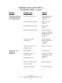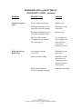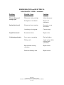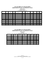
1
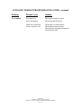
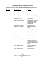
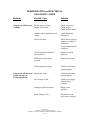
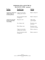
POLAR TEMP
ICE TRANSPORT with TRAILER, TRUCK
BODY, and PALLET LOAD SERIES
INSTALLATION, OPERATION, &
MAINTENANCE MANUAL
Model: 3’ x 7’
Model: 4’ x 8’
Model: 4’ x 8’ Super Sized
Model: 5’ x 9’
Model: 5’ x 10’
Model: 7’ x 12’
Model: 7’ x 16’
1st Flags Drive
Austell, GA 30168
Visit our website:
www.polartemp.com
TABLE OF CONTENTS
Disclaimer . . . . . . . . . . . . . . . . . . . . . . . . . . . . . . . . . . . . . . . . . .
Inspection and unpacking . . . . . . . . . . . . . . . . . . . . . . . . . . . . . .
Installation . . . . . . . . . . . . . . . . . . . . . . . . . . . . . . . . . . . . . . . . . .
Operation . . . . . . . . . . . . . . . . . . . . . . . . . . . . . . . . . . . . . . . . . . .
•
•
•
•
Electrical
Start-up
Temperature Control
Load with Bagged Ice
Maintenance . . . . . . . . . . . . . . . . . . . . . . . . . . . . . . . . . . . . . . . .
•
•
Page 7 thru 10
Refrigeration
Defrosting
•
•
•
•
•
•
•
•
•
•
•
Page 4
Page 5
Page 5
Page 6 and 7
Cold Wall (CW)
Auto Defrost (AD)
Finish
Axle
Tires and Wheels
Hitch Jack
Safety Chains
Signal, Stop and Safety Lights
Break Away Kit
Hitch Assembly
Body
•
•
•
•
•
Insulated Body
Door, Gasket and Frame
Door Hinges and Lock
Interior and Auxiliary Lighting
Body Mounting
Automatic Defrost Wiring Diagram . . . . . . . . . . . . . . . . . . . . . .
Cold Wall Wiring Diagram . . . . . . . . . . . . . . . . . . . . . . . . . . . . .
Automatic Defrost Trouble Shooting Guide . . . . . . . . . . . . . . . .
Cold Wall Troubleshooting Guide . . . . . . . . . . . . . . . . . . . . . . . .
Refrigeration and Electrical Diagnostic Guide . . . . . . . . . . . . . .
Refrigeration Data and Specifications . . . . . . . . . . . . . . . . . . . . .
Trailer Tips . . . . . . . . . . . . . . . . . . . . . . . . . . . . . . . . . . . . . . . .
Frequently Asked Questions . . . . . . . . . . . . . . . . . . . . . . . . . . . .
Mounting Hole Pattern Drawing . . . . . . . . . . . . . . . . . . . . . . . . . . .
Trailer Wiring Diagram . . . . . . . . . . . . . . . . . . . . . . . . . . . . . . . . .
Page 11
Page 12
Page 13 thru 14
Page 15
Page 16 thru 20
Page 21
Page 22, 23 and 24
Page 25, 26 and 27
Page 28 thru 33
Page 34
Polar Temp
A Southeast Cooler Corporation Company
Installation, Operation & Maintenance Manual Part Number 0000886
2 of 37
Policy Statement . . . . . . . . . . . . . . . . . . . . . . . . . . . . . . . . . . . . .
•
•
•
•
•
•
Page 35 and 36
Warranty
Parts Orders
Method of Shipment
Ship Dates
Return of Merchandise
Pricing
Factory Sales Locations . . . . . . . . . . . . . . . . . . . . . . . . . . . . . .
Page 37
Revision Level :
Original : February 19, 2004
Revision: January 31, 2005
Revision: April 21, 2005
Revision: April 17, 2006
Revision April 26, 2011
Polar Temp
A Southeast Cooler Corporation Company
Installation, Operation & Maintenance Manual Part Number 0000886
3 of 37
DISCLAIMER
Polar Temp is committed to continuous material and product improvements. This
manual is subject to modification without notice without incurring responsibility for
previously sold merchandisers and components.
Thank you for purchasing from Polar Temp.
Polar Temp
A Southeast Cooler Corporation Company
Installation, Operation & Maintenance Manual Part Number 0000886
4 of 37
INSPECTION AND UNPACKING:
Polar Temp Ice Transport (IT), Truck Bodies (TB) and Pallet Load (PL) units are
individually inspected and carefully packaged to ensure each unit arrives without
damage.
• Upon receipt, immediately inspect the units for any evidence of
shipping damage while the delivery truck driver is there. If the unit is
damaged, document damage on the bill of lading and give the driver a copy.
Notify the delivering carrier immediately and request a damage inspection and
claim. Polar Temp is not responsible for damage to the unit during transit. A
unit damaged in transit is the delivering carrier’s responsibility.
• Remove the wood shipping base and other protective materials. First,
carefully cut the steel bands that extend around the top and through the
shipping base area. After removing the bands, again be careful as the
remaining wood protective material is removed from around the unit. The
wood protective material at the front and rear of the unit should be removed
prior to the top material. Be aware that the top protective material could fall.
Ask for help, as this material is being removed. Finally, remove the plastic
protective wrap from the unit.
INSTALLATION
Carefully raise the unit into position with a forklift or other safe device rated to lift the
load and slide it into the pickup box, trailer or pallet load location. Approximate weight
of the model 3’ x 7’ is 700 lbs., model 4’ x 8’ is 1200 lbs., model 5’ x 9’ is 1500 lbs.,
model 5’ x 10’ is 1700 lbs, model 7’ x 12’ is 2000 lbs and model 7’ x 16’ is 2500 lbs.
• The mobile unit, whether it be a trailer or pickup truck should be strong
•
•
•
•
enough to support the unit with a load of ice. Be sure to check the load
capacity of the mobile unit prior to installing the box on it.
It is essential that auto-defrost models be parked on a level surface to allow
defrost water to drain properly. If defrost water does not drain, it will freeze
in the drain pan which can eventually cause the fans to seize.
Auto-defrost models should be parked to prevent the evaporator drain hose
from being kinked or hose opening from being obstructed.
Adequate space should be allowed around the exterior walls of the unit to
allow for evaporation of any condensation that may occur on exterior surfaces.
The units should be located in a shaded area away from direct sunlight for the
most economical operation. . Good ventilation for the refrigeration system is
required. DO NOT BLOCK AIRFLOW TO THE CONDENSING UNIT.
Polar Temp
A Southeast Cooler Corporation Company
Installation, Operation & Maintenance Manual Part Number 0000886
5 of 37
• A minimum 115-Volt, 15 or 20 Amp grounded power source should be
provided within a range of the power cord. USE ONLY PROPERLY
SIZED EXTENSION CORDS. A 12 GUAGE MINIMUM CORD IS
RECOMMENDED, BUT PROPERLY SIZED CORDS DEPEND ON
THE LENGTH OF TRAVEL FROM THE POWER SOURCE TO THE
UNIT.
OPERATION:
Electrical:
The electrical power supplied to the unit must be as identified on the serial
number data plate located on the inside the unit. Electrical service connections
must be in accordance with the National Electrical Code, state code and any local
codes that may apply. All units are equipped with a power cord and a 3-prong
plug. WARNING: Improper use or removal of the grounding plug can result
in a risk of electric shock!
Be sure to use a grounded electrical receptacle with a fused circuit sized correctly
for the electrical load. Extension cords may decrease the voltage to the unit and
ultimately cause the compressor or other component failure. The unit data plate
indicates the recommended maximum overcurrent protective device size.
Note: Some outdoor locations require ground fault interrupt (GFI) outlets. These
outlets may trip upon condensing unit start. Refrigeration equipment is exempt in
some areas from GFI requirements. Local electric codes should be checked.
This units require 120-volt ac and a 20-amp breaker. The unit was shipped with a
10 gauge, 25 foot, 3 conductor power cord. If you require a longer cord, it should
be of heavier gauge per the chart below.
Cord Length
Up to 50 feet
Up to 100 feet
Up to 150 feet
Up to 200 feet
Minimum Wire Size
10 AWG
8 AWG
6 AWG
4 AWG
Using a power cord of inadequate size can result in hard starting, inefficient
operation and shortened compressor life.
Polar Temp
A Southeast Cooler Corporation Company
Installation, Operation & Maintenance Manual Part Number 0000886
6 of 37
Start Up:
Plug the unit power cord into the properly sized electric receptacle outlet. Turn
the power on-off switch to the ON position. The condensing unit will start and
continue to operate until air temperature inside the storage space reaches +10 to
+20 degree F.
To stop refrigeration of the transport turn the power switch to the OFF position.
Temperature Control:
The unit temperature is maintained by a thermostat that cycles the condensing unit
on and off automatically. On auto-defrost (AD) models, the temperature control
is located in the control box near the condensing unit housing. On cold wall
(CW) models, the temperature control is also located in the control box near the
condensing unit housing.
The temperature is adjusted by turning the thermostat control knob clock-wise for
colder temperature and counter-clockwise for warmer temperatures. Turning the
control knob fully counter-clockwise will shut power off to the compressor. DO
NOT re-adjust the internal adjustments of the thermostat without consulting Polar
Temp.
Loading the unit with bagged ice:
After the IT is operating at required temperature, load it with bagged ice. Bagged
ice should NOT be stacked such that it will obstruct air flow in automatic defrost
blower coil. Cold wall units should have ice stacked to allow open-air access to
thermostat sensor at upper rear interior. Approximately 3” needs to be clear from
top of stacked ice to top of inside interior for effective refrigeration and ice
storage.
MAINTENANCE:
Refrigeration: WARNING – disconnect electrical power before cleaning. Clean
refrigeration cover grill openings, condenser fins, and condenser fan blades at least two
(2) times per year, more often if needed. A dirty condenser will cause the refrigeration
system to become less efficient, and may lead to compressor failure. Clean the
evaporator coil and fan blades on auto-defrost units as required.
• Clean condenser coil fins with a fine bristle brush or vacuum
• Routinely check wiring harnesses for loose connections or broken
insulation
•
Defrosting: Frost cannot be avoided. It develops from moist air entering storage area
when the door is opened. Frost forms on the cold evaporator on automatic defrost units
and on the walls (evaporator) of a cold wall refrigeration system. When the frost
Polar Temp
A Southeast Cooler Corporation Company
Installation, Operation & Maintenance Manual Part Number 0000886
7 of 37
accumulation on the evaporator becomes too heavy, it acts as an insulator, which hinders
the refrigeration efficiency.
• Excess frost or water on the interior of the unit should be removed or
drained. Do not allow water to stand in the unit.
Cold Wall (CW): Cold Wall type units utilize the interior wall surface as the
refrigeration evaporator. Frost accumulation will occur on all wall surfaces. The
unit can be defrosted by conventional methods using a wooden paddle or plastic
scraper. Care must be exercised to prevent damaging piping and control parts.
Do not use a sharp instrument to “chop” the frost from the interior surface as you
may do irreparable damage.
Auto-Defrost (AD): Auto-Defrost (sometimes referred to as “electric defrost”)
type unit utilize a evaporator with an electric defrost heating element to melt the
frost off the evaporator coil. The defrost cycle is controlled by the defrost timer
which energizes the defrost heating element. The defrost timer is located in the
condensing unit compartment or control box. The control is pre-set to
periodically place the system in a defrost cycle automatically every six (6) hours.
The length of the defrost cycle is approximately 14 to 16 minutes. The timer used
is adjustable to set for your specific requirements.
Finish: Schedule periodic cleaning of the unit interior and exterior. The unit can be
cleaned with a mild detergent and water. DO NOT USE strong detergents, abrasive
cleaners, or solvents, as they are likely to leave objectionable odors, which may be
absorbed, by the ice. Do not use wax or polish on the interior for the same reason. Wash
exterior surfaces with a mild soap and warm water applied with a soft sponge or cloth.
Wax exterior to maintain appearance and to protect the finish just as you would an
automobile.
Axle
The safest and most proven suspension system available comes with springs and
equalizers. This allows all four tires to remain in contact with the road. All two axle
trailers come standard with electric brakes on the rear axle. (Hydraulic brakes are
optional). Easy lube hubs allow you to grease bearings without disassembly.
Tires and Wheels
White painted corrosion resistant wheels that exceed the rated capacity of the trailer are
standard. Highest quality bias ply tires are used to match trailer capacity. These properly
matched accessories eliminate possibilities of sway. Wheels are fastened adequately with
five lug nuts. Check the lug nuts and tire pressures periodically for safe travel. Refer to
the VIN plate for recommended tire pressure and tire size. Replace tires with identical
size tires as was received on the trailer. WARNING: Failure to follow these instructions
may result in wheel loss which can cause injury or death! Torque wheel nuts to 90-120 ft.
lbs. before first road use. Re-torque to 90-120 ft. lbs. after 10, 25, and 50 miles. Check
periodically thereafter. Rev. 4/17/06
Polar Temp
A Southeast Cooler Corporation Company
Installation, Operation & Maintenance Manual Part Number 0000886
8 of 37
Hitch Jack – Trailer Units
A side wind tongue jack with foot is located at the hitch allowing for easy raising and
lowering for hook-up and disconnect from your vehicle. Lubricate the gears periodically.
Safety Chains – Trailer Units
6-foot safety chain with hooks is provided on all trailers. Examination of the chains and
the welded connecting area should take place before each trip.
Signal, Stop, and Marker Lights – Trailer and Truck Bodies
A standard 7-pin trailer light kit is used. Keep the electrical connector lubricated with an
electrical lubricant. Always check lights before traveling.
Break-A-Way Kit – Trailer Units
Another important safety feature is the Break-A-Way kit that in the event of the trailer
coming detached from a vehicle, the Break-A-Way Kit powered separately from the
pulling vehicle activates the trailer brakes. Check operation of the breakaway hitch
before every move. Note: The cable from the break-away-switch to the vehicle
pulling the trailer should be slightly shorter than the safety chains so the trailer
brakes will be activated prior to the chain activation. Rev. 4/17/06
Hitch Assembly – Trailer Units
Lubricating the ball coupling area of the hitch periodically is recommended to reduce
friction and premature wear.
BODY
Insulated Body
The body is made with rock hard, high performance polyester prepainted sheetmetal
exterior wall surface and galvanized G90 interior wall surface insulated with CFC-free
foamed-in-place polyurethane. The floor is made with three 7” wide channels spaced for
standard pallets, with 22 Ga. G90 galvanized sheetmetal and robust slip resistant diamond
plate aluminum.
Door, Gasket and Frame
Door openings are formed with a recessed type PVC channel allowing the door to be
recessed into the opening providing a rigid, well-insulated entry. The door has a
magnetic gasket providing a positive seal. Gaskets should be checked for tears or any
other problems that would cause loss of seal. Replace torn/worn gaskets to maintain
correct temperature and refrigeration efficiency. Hinges exposed to harsh environmental
conditions may require a lubricant for ease of operation. Spray light penetrating oil on
the spring loaded hinge cartridge to extend the hinge life.
Polar Temp
A Southeast Cooler Corporation Company
Installation, Operation & Maintenance Manual Part Number 0000886
9 of 37
Door Hinges and Lock
Maintenance free heavy-duty hinges are fastened to the body with stainless steel bolts
into 1/4” thick aluminum angle extending the full height of the door opening. Hinges are
mounted to the door with stainless steel bolts into 1/4” plate. Doors have padlockable
feature, inside safety release and they swing open 180° offering clear entry into the body.
Interior and Auxiliary Lighting
Both 12 volt (optional) and 120 volt interior lighting is supplied on the interior of the
trailer. The 120V lighting is activated as the door is opened. For 12-volt use, a separate
switch must be activated. An optional spotlight is available for exterior lighting.
Body Mounting
Trailer bodies are mounted securely between the 1/4” x 2” x 4” tubular frame of the
trailer with 1/2” diameter bolts. Robust 1/4” aluminum angle wall bumpers are used at
each side of the interior floor where the bolts extend through to the heavy angle iron
supports of the trailer. A drawing showing hole patterns for mounting transport units to
the trailer or truck is included with this manual.
Polar Temp
A Southeast Cooler Corporation Company
Installation, Operation & Maintenance Manual Part Number 0000886
10 of 37
AUTOMATIC DEFROST TROUBLESHOOTING GUIDE
If refrigerant valves must be opened, a qualified technician should be notified to perform the work.
Problem
Ice is melting
Possible Cause
Solution
Power switch is in OFF position
Turn switch to ON
position.
Ice bags are blocking air flow
Move ice bags accordingly.
Thermostat setting
Normal setting is between
+10° and +20° F on the dial.
Jump terminals on thermostat
to check, if unit starts,
replace thermostat.
Evaporator fan motors are
operating but the fan blade
is not turning
Check to see if fan blade is
slipping on the motor shaft.
Condenser coil is dirty
Clean condenser.
Incorrect refrigerant charge
Check sight glass for bubbles
indicating wrong charge.
Add refrigerant. Locate
refrigerant leak.
Condenser fan motor and
compressor are not running
Check power supply.
Check if defrost timer is
stuck in defrost mode
Check if compressor is hot,
this may indicate that
condenser fan motor has
failed causing thermal
overload on compressor to
trip.
Condenser fan motor is not
operating
Check electrical power to
motor.
Compressor is not operating
Check electrical power, relay,
overload protector, start
capacitor and compressor
motor.
Polar Temp
A Southeast Cooler Corporation Company
Installation, Operation & Maintenance Manual Part Number 0000886
13 of 37
AUTOMATIC DEFROST TROUBLESHOOTING GUIDE - continued
Problem
Possible Cause
Solution
Ice is melting
Evaporator fan
motor not running
Check power supply to motor
Check for faulty fan motor
Check for ice build-up
on the evaporator coil
Check power to defrost heater
Check defrost heater for heat
Check defrost termination thermostat
Check defrost timer
Polar Temp
A Southeast Cooler Corporation Company
Installation, Operation & Maintenance Manual Part Number 0000886
14 of 37
COLD WALL TROUBLESHOOTING GUIDE
If refrigerant valves must be opened, a qualified technician should be notified to perform the work.
Problem
Possible Cause
Solution
Ice is melting
Power switch is in OFF position
Turn switch to ON
position
Thermostat setting
Thermostat should be set
between +10° and +20° F.
Condenser coil is dirty
Clean condenser
Incorrect refrigerant charge
Check sight glass for bubbles
indicating wrong charge.
Add refrigerant. Locate
refrigerant leak.
Condenser fan motor and
compressor are not running
Check power supply.
Check if thermostat has
failed.
Check if compressor is hot
which may indicate that the
condenser fan motor has
failed causing the thermal
overload in the compressor to
trip.
Condenser fan motor is
not operating
Check electrical power to
motor
Compressor is not operating
Check electrical power to
compressor. Check relay,
overload protector and start
capacitor. Check compressor
motor.
Check thermostat setting
Thermostat should be set
between 4 and 6
Check refrigerant charge
Adjust if necessary
Polar Temp
A Southeast Cooler Corporation Company
Installation, Operation & Maintenance Manual Part Number 0000886
15 of 37
REFRIGERATION and ELECTRICAL
DIAGNOSTIC GUIDE
Problem
Possible Cause
Solution
Compressor will not start
(no hum)
Be sure power is being
supplied to the unit.
Check power cord
Check plug in
Check breaker switch
Ambient colder than thermostat
setting
Adjust thermostat
if necessary
Unit is in defrost
Allow defrost cycle to
complete, usually 1520 minutes,
or turn manual control
on defrost
Overload protector stuck in
open position
Replace overload
protector
Thermostat stuck in open
position
Replace thermostat
Wiring improper or loose
Check actual wiring
against diagram
Improperly wired
Check actual wiring
against diagram
Low voltage to unit
Check power supply.
Contact Power
Company
Starting capacitor defective
Replace start
capacitor
Relay failing to close
Determine reason
and correct or replace
Compressor will not start
(hums, but trips on
overload protector)
Polar Temp
A Southeast Cooler Corporation Company
Installation, Operation & Maintenance Manual Part Number 0000886
16 of 37
REFRIGERATION and ELECTRICAL
DIAGNOSTIC GUIDE - continued
Problem
Possible Cause
Solution
Compressor will not start
(hums, but trips on
overload protector)
Compressor motor has a
winding open or shorted
Replace compressor
Internal mechanical trouble
in compressor
Replace compressor
Improperly wired
Check wiring
against diagram
Low voltage to unit
Determine reason
and correct
Relay failing to open
Determine reason
and correct or replace
Compressor motor has a
winding open or shorted
Replace compressor
Internal mechanical trouble
in compressor
Replace compressor
Compressor starts, but
does not switch off of
start winding
Polar Temp
A Southeast Cooler Corporation Company
Installation, Operation & Maintenance Manual Part Number 0000886
17 of 37
REFRIGERATION and ELECTRICAL
DIAGNOSTIC GUIDE - continued
Problem
Possible Cause
Solution
Compressor starts and
runs, but short cycles
on overload protector
Low line voltage to unit
Check power supply
Contact Electric
Company
Overload protector defective
Replace overload
protector
Starting capacitor defective
Replace start
capacitor
Excessive discharge pressure
Check ventilation,
restrictions in cooling
medium, restrictions
in refrigeration
system
Compressor too hot return gas hot
Check refrigerant
charge (fix leak) add
refrigerant if
necessary
Compressor motor has a
winding shorted
Replace compressor
Dirty condenser
Clean condenser
Refrigerated space has
excessive load.
Reduce load. Check
for open door or bad
door gasket.
Defrost
Compressor runs a
long time or
continuous
Evaporator coil iced
Thermostat contacts stuck
in closed position
Replace thermostat
Shortage of refrigerant
Fix leak, add charge
Polar Temp
A Southeast Cooler Corporation Company
Installation, Operation & Maintenance Manual Part Number 0000886
18 of 37
REFRIGERATION and ELECTRICAL
DIAGNOSTIC GUIDE - continued
Problem
Possible Cause
Solution
Starting Capacitor
open
Relay contacts not closing
Replace relay
Prolonged operation on start
cycle due to low line voltage
Determine reason
and correct
Prolonged operation on start
cycle due to improper relay
Replace relay
Excessive short cycling
(Compressor starts and runs
for a short cycle)
See “Compressor
starts and runs, but
short cycles on
on overload
protector” section
Line voltage too high
or too low
Determine reason
and correct
Excessive short cycling
Determine reason
and correct (see
Compressor starts
and runs but short
Short cycles)
Relay being influenced
by loose vibrating mounting
Remount relay rigidly
Relay defective or
burned out
Polar Temp
A Southeast Cooler Corporation Company
Installation, Operation & Maintenance Manual Part Number 0000886
19 of 37
REFRIGERATION and ELECTRICAL
DIAGNOSTIC GUIDE - continued
Problem
Possible Cause
Solution
Warm refrigerated
storage space
Thermostat setting too high
Adjust thermostat
Inadequate air circulation
Improve air
circulation
Evaporator fan not running
Determine reason
and correct
Overcharge of refrigerant
Correct charge
Liquid line frosted
Restriction in drier
Replace drier
Condensing unit noisy
Loose parts or mountings
Find and tighten
Tubing rattle
Apply sponge rubber
between parts
(Armaflex)
Bent fan blade causing
vibrations
Replace blade
Fan motor bearings worn
Replace motor
Suction line frosted
Polar Temp
A Southeast Cooler Corporation Company
Installation, Operation & Maintenance Manual Part Number 0000886
20 of 37
POLAR EXPRESS ICE TRANSPORTER
REFRIGERATION DATA AND SPECIFICATIONS
R404A system
Automatic Defrost
* Actual minimum amp draw may vary.
Model
HP
Condensing
Unit
Coil
Metering
Device
Defrost
Heater
Refrigerant
Type
Charge
Ounces
Min.
Amps*
Volts
Max.
Amps
3’ x 7’
1/2
Danfoss
2 fan
TX Valve
400w
404a
18
14.3
110V
20
4’ x 8’
1/2
Copeland
3 fan
TX Valve
600W
404A
64
22.2
115V
30
5’ x 9’
3/4
Copeland
3 fan
TX Valve
800W
404A
64
22.2
115V
30
5’ x 10’
3/4
Copeland
3 fan
TX Valve
800W
404A
64
22.2
115V
30
7’ x 12’
3/4
Copeland
3 fan
TX Valve
800W
404A
64
22.2
115V
30
7’ x 16’
3/4
Copeland
3 fan
TX Valve
800W
404A
64
22.2
115V
30
POLAR EXPRESS ICE TRANSPORTER
REFRIGERATION DATA AND SPECIFICATIONS
R404A system
Cold Wall
* Actual minimum amp draw may vary.
Model
HP
Condensing
Unit
Metering
Device
Refrigerant
Type
Charge
Ounces
Min.
Amps*
Volts
Max.
Amps
3’ x 7’
1/2
Danfoss
TX Valve
404A
18
13.1
110V
15
4’ x 8’
1/2
Copeland
TX Valve
404A
64
19.4
115V
30
5’ x 9’
3/4
Copeland
TX Valve
404A
64
22.2
115V
30
5’ X 10’
3/4
Copeland
TX Valve
404A
64
22.2
115V
30
Polar Temp
A Southeast Cooler Corporation Company
Installation, Operation & Maintenance Manual Part Number 0000886
21 of 37
Trailer Tips
Tip #1: Always make sure the tires on your trailer are inflated to the
proper air pressure as specified by the tire manufacturer.
Tip #2: Check wheel fastener torque frequently. Each time a wheel is
removed and re-mounted, the lug nuts should be checked and retightened after ten (10) miles, twenty five (25) miles and fifty (50)
miles and periodically thereafter.
Tip #3: Use the proper wheel fastener and torque range as specified
by the wheel manufacturer. Excessive torque can permanently damage
the wheel while insufficient torque can result in stud failure.
Tip #4: Remember to inspect and service wheel bearings regularly as
stated in your Operation & Maintenance Service Manual.
Tip #5: Use the proper bearing adjustment method as stated your
Operation & Maintenance Service Manual to assure reliable, long life
performance.
Tip #6: Wheels and tires must be properly matched to each other to
ensure safe, reliable performance.
Tip #7: Do not exceed the capacity of your trailer’s running gear.
Overloading can seriously degrade the life of the various components,
result in unsafe braking and may lead to catastrophic failure.
Tip #8: When using after-market wheels, make sure that they fit
properly and that the wheel studs are long enough to ensure proper
thread engagement.
Tip #9: Remember to have your tires rotated and balanced according
to the tire manufacturer’s recommendations.
Tip #10: Check your brakes before every use to make sure they are
functioning properly.
Tip #11: It is very important to pull your trailer so that it is running
level. If the hitch is too high or too low, the trailer axle(s) may be
unevenly loaded and can result in premature tire or axle failure.
Tip #12: Inspect your emergency breakaway devices to make sure
they are in good working order before each use.
Tip #13: When loading your trailer, make sure enough weight is being
carried on the hitch to ensure proper weight distribution and good
handling.
Tip #14: Never fix an air leak of your wheel by putting a tube in the
tire. The only safe solution for a leaky wheel is to replace it.
Tip #15: Support the back of the trailer at the ramps when loading up
equipment or vehicles to prevent overloading the rear axle.
Tip #16: Remember to use recommended safety tools, personal
protection, and procedures when servicing your trailer.
Polar Temp
A Southeast Cooler Corporation Company
Installation, Operation & Maintenance Manual Part Number 0000886
22 of 37
Tip #17: Follow the trailer manufacturer’s guidelines for lifting and
supporting trailer when servicing running gear.
Tip #18: Use caution when servicing brakes since some lining
materials can contain asbestos.
Tip #19: Remember to lubricate the moving parts in your brake per
the manufacturer’s recommendations. Proper maintenance will prevent
them from seizing up. Do not allow grease or oil to contaminate the
linings, drum surfaces or magnets.
Tip #20: The Gross Axle Weight Rating (GAWR) of your running gear
is determined by the lowest rated component in the assembly. The
capacity of the wheel, tire, axle, brake, springs, rubber and hub are all
considered.
Tip #21: The location of the load on a trailer will affect the ride
characteristics. Too little load on the hitch can cause the trailer to
wander or sway. Too much hitch load can overload your towing
vehicle’s suspension.
Tip #22: If you experience uneven tire wear, it is important to note
the type and nature of the wear pattern in order to determine the
cause. Contact your tire dealer to assist in troubleshooting the
problem.
Tip #23: Spread axle mounting will lend support to frame structure
but will result in more tire wear from side scrubbing when negotiating
sharp turns or corners.
Tip #24: Axles should be spaced far enough apart the allow a
minimum of 1" clearance between the tires. More space would be
required if tire chains are to be used.
Tip #25: Widest possible track and axle mounting provides the best
design for stability, especially when hauling high center of gravity
loads.
Tip #26: Bump clearance is the distance from the top of a leaf spring
mounted axle to the bottom of the frame. If this distance is too small
the axle may come in contact with the frame and result in damage to
axle.
Tip #27: Make sure there is enough clearance around the sides and
top of the tires to prevent the tire from rubbing on the frame or other
trailer structure.
Tip #28: Oil lubricated bearings are best suited for trailers that are
used continuously. Grease will provide better protection for bearings
during long periods of storage.
Tip #29: Axles fitted with Dual wheels should never be operated with
only one wheel in place or with one of the two tires flat. Doing so can
seriously overstress the wheel bearings and result in bearing failure.
Polar Temp
A Southeast Cooler Corporation Company
Installation, Operation & Maintenance Manual Part Number 0000886
23 of 37
Tip #30: Mixing aluminum wheels and steel dual wheels will result in
galvanic corrosion between the two dissimilar metals. This corrosion
can cause wheels to loosen and possibly result in stud failure and
wheel run-off.
Tip #31: Replace brake shoes if the linings have been contaminated
with oil or grease, are less that 1/16" thick, or are abnormally scored
or gouged. Minor cracks in linings are not detrimental unless chunks of
the linings are missing.
Tip #32: Remember that your new brake shoes need to be burnished
or "seated in". This process may take quite a few stops to get the
shoes fully worn in before maximum brake performance can be
achieved.
Polar Temp
A Southeast Cooler Corporation Company
Installation, Operation & Maintenance Manual Part Number 0000886
24 of 37
Frequently Asked Questions
BEARINGS - How often should I grease the bearings?
Along with bearing adjustment, proper lubrication is essential to the current function and
reliability of your trailer axle. Bearings should be lubricated every 12 months or 12,000
miles.
BEARINGS - What is the proper bearing adjustment procedure and recommended
grease?
Please review the Dexter Service Manual for instructions and specifications relating to
bearing adjustment and lubrication. WARNING: It is important to NOT mix different
types of grease thickeners. The grease that Dexter Axle uses has a Lithium Complex
thickener. Mixing our grease with a Barium, Calcium, Clay, or Polyurea soap based
thickener agent will cause adverse affects. This may include causing the two greases to
harden, separate, become acidic, or pose other hazards and damage to the bearings.
BRAKES - How often should I adjust my brakes?
Dexter recommends that manual adjust brakes should be adjusted . . . 1) After the first
200 miles of operation when the brake shoes and drums have "seated" 2) At 3,000 mile
intervals 3) Or as use or performance requires.
BRAKES - Why aren't my electric brakes working?
Most electric brake malfunctions that cannot be corrected by either brake adjustment or
synchronization adjustments of your brake controller, can generally be traced to electrical
system failure. Mechanical causes are ordinarily obvious (i.e. bent/broken parts, worn out
linings or magnets, seized lever arms or shoes, scored drums, etc.). A voltmeter and
ammeter will be essential tools for proper troubleshooting of electric brakes. NOTE:
After replacing your brake shoes and magnets you will experience a decrease in braking
performance until the components have worn into the drum and finished the burnishing
process. This process requires many stops to bring the new shoe's performance back to
normal. This may take more than 100 stops to finish this break-in period with stops of 20
mph decreases in speed. Please refer to the Dexter Service Manual for detailed
troubleshooting instructions to further determine the cause of poor brake performance.
BRAKES - Why can't I lock and slide my electric brakes?
On an unloaded trailer, you may be able to lock up your brakes if your electric brake
controller is supplying full amperage to the brakes. When loaded to capacity, you may
not be able to lock your brakes as electric brakes are designed to slow the trailer at a
controlled rate, and not designed to lock up the wheels on a fully loaded trailer. Our
brakes are designed to meet all applicable safety standards. All of our brakes will perform
better after numerous burnish stops to seat the brake linings to the drums.
Polar Temp
A Southeast Cooler Corporation Company
Installation, Operation & Maintenance Manual Part Number 0000886
25 of 37
BRAKES - Why do I have to adjust my brakes?
Brakes must be adjusted to compensate for the lining and drum wear that occurs during
the use of the braking system. Some brakes require manual adjustment to move the
linings closer to the drum. Refer to the brake adjustment section of the OPERATION
MAINTENANCE MANUAL for your style of brakes. Other brakes may have an
automatic brake adjuster such as the automatic slack adjusters for air brakes.
BRAKES - Why do my brakes and hubs get so hot?
Braking systems use friction to slow the vehicle and the energy used to slow the trailer is
converted to heat. Dexter brakes are designed to operate up to extremely high
temperatures during hard braking application. This heat is noticeable on the hub and
drums and is to be normally expected on a properly functioning brake. If a brake is
malfunctioning and running excessively hot, this can be noticed by smoking brakes or the
paint burning off of the brake drum.
TOWING - How do I determine hitch weight?
The hitch weight for conventional, bumper type hitches should be 10-14% of the gross
weight of the vehicle. The remaining 86-90% of the load will be carried on the running
gear. The hitch weight for 5th wheel and gooseneck type trailers should be 15-20% of the
gross weight of the vehicle, with the remaining 80-85% of the load being carried on the
running gear.
WHEELS & TIRES - Can I change to aluminum wheels?
Aluminum wheels are thicker through the mounting bolt area and may not leave enough
stud length for proper nut engagement. Consult the wheel manufacturer for stud length
and mounting face requirements and wheel nut torque.
WHEELS & TIRES - Can I use wheels with greater offsets?
Wheel offset is the distance from the mounting surface to the centerline of the tire. Dexter
Axle bearing sets are designed for wheel with 0 to ½" inset. Exceeding this offset will
shorten bearing life and may lead to dangerous bearing failure.
WHEELS & TIRES - What tires can I use on these wheels?
Wheels and tires must be matched. The wheel will have a label stating it's rim diameter,
width and contour. The tire selected must be approved by the Tire and Rim Association
for use on that particular size wheel. The tire capacity selected should not exceed the
capacity rating of the wheel. The tire inflation pressure must not exceed the pressure
rating of the wheel. WARNING - The use of tires that are not approved for use on a
wheel could result in explosive separation of the tire and wheel and could cause a serious
accident.
Polar Temp
A Southeast Cooler Corporation Company
Installation, Operation & Maintenance Manual Part Number 0000886
26 of 37
WHEELS & TIRES - Why do I need to re-torque my trailer wheels when I don't do
that on my truck?
Trailer wheels carry substantially more weight than tow vehicle wheels of the same size
and see more disc flexing due to side loading stresses. It is necessary to re-torque them
several times until the wheel nut torque stabilizes. This is especially true for new wheels
that need to have the paint worn away at the hub mounting face and under the wheel nuts.
WARNING: Be very careful to use only the recommended wheel fastening torque
amount as specified for that wheel and fastener. It is possible to permanently damage a
wheel that has been over torqued and may cause the loss of that wheel from the trailer.
For additional information go to
www.dexteraxle.com
Polar Temp
A Southeast Cooler Corporation Company
Installation, Operation & Maintenance Manual Part Number 0000886
27 of 37
POLAR TEMP
TRANSPORT, TRUCK BODY and PALLLET LOAD UNIT POLICY
Warranty
Seller warrants the goods sold to be free from defects in materials and workmanship,
under normal conditions and use for the following period of time:
Compressor – five (5) years from the original date of shipment
Merchandiser Parts – one (1) year from the original date of shipment
Labor – 60 days (Purchaser’s authorized service technician must contact factory
for approval).
This warranty applies to goods installed in the continental United States, Canada and the
Caribbean Islands only. Seller’s sole obligation under this warranty shall be limited to
repair or replacement of any part or parts of said goods, F.O.B. Seller’s factory which
proves defective within the applicable warranty period. Seller reserves the right to
inspect allegedly defective goods and to require the return, at the Buyer’s expense, of
goods for the purposes of inspection. This warranty shall not apply to any good, or any
part thereof, which has been subject to any accidents or negligence or abuse of misuse,
alteration or detrimentally affected its physical condition, use or operation qualities.
Parts Orders
Please order parts by Polar Temp part number as listed in the replacement parts catalog.
Call Polar Temp factory sales location for replacement parts catalog. Always have
available the model and serial number of the cabinet, and in some cases the
manufacturers name and model number of the part. In case of warranty replacement this
information is required. Parts will not be issued as warranty or warranty authorized
without this information.
Method of Shipment
Every shipment is carefully packed for domestic shipment and labeled to prevent damage
or loss in transit. Specify where shipment should be sent, freight, express, parcel post,
airfreight or united parcel. If no preference is given, or in case of freight shipment, the
routing is not furnished, shipment will be made according to our discretion without
liability of any kind on our part for each selection. We welcome your suggestions on
preferred carriers for better service.
Common carrier shipments are forwarded freight collect. Under pre-approved
circumstances, where transportation charges are prepaid, they will be added to the
invoice. Please note that prepaid freight charges are subject to sales tax if a signed sales
tax exemption certificate is not on file with Polar Temp. All UPS shipments will be
prepaid and added to the invoice.
Polar Temp
A Southeast Cooler Corporation Company
Installation, Operation & Maintenance Manual Part Number 0000886
35 of 37
POLAR EXPRESS ICE
TRANSPORTER POLICY
Ship Dates
Promise of delivery represents only our best estimate of the time required completing the
work and shipping the product from our plant. Orders are accepted with the
understanding that shipping dates are approximate and subject to change because of
factory conditions, fires, supplier delays, material shortages, civil or military authority,
mandatory priority and/or other causes beyond our knowledge or control.
Return Of Merchandise
No returned merchandise will be accepted without prior authorization from Polar Temp.
When orders have been correctly filled, and merchandise is returned, a 10% handling
charge plus reconditioning charges, if any, will be applied. No return shipment will be
accepted unless authorized in advance and the freight is prepaid. During the warranty
period, in order to obtain proper credit from our vendors, all defective parts must be
returned within 45 days, freight prepaid to our factory for repair, replacement or credit.
Pricing
All prices listed are F.O.B. Lithia Springs and/or Austell, Georgia, and are subject to
change without notice.
Polar Temp
A Southeast Cooler Corporation Company
Installation, Operation & Maintenance Manual Part Number 0000886
36 of 37
FACTORY SALES LOCATIONS
Tennessee
1-865-984-5945
Texas
1-866-598-4206
North Carolina
1-866-827-3232
California
1-866-746-0437
Georgia
1-770-945-2181
Colorado
1-719-522-0955
Polar Temp
A Southeast Cooler Corporation Company
Installation, Operation & Maintenance Manual Part Number 0000886
37 of 37