1
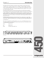
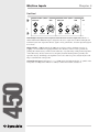
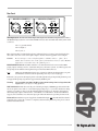
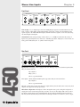
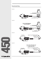
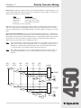
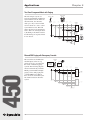
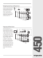
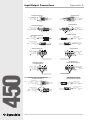
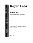
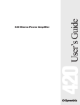
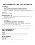
User’s Guide
450
450 Dual Zone Priority Mixer
Table of Contents
1
Chapter 2 Operator Safety Summary
2
Chapter 3 Fast Setup
3
Chapter 4 Mic/Line Inputs
4
Chapter 5 Stereo Line Inputs
6
Chapter 6 Output Zone Master
7
Chapter 7 Priority Override Muting
9
Chapter 8 Applications
10
Chapter 9 Troubleshooting
12
Chapter 10 Specifications
13
Chapter 11 Warranty & Service
14
Appendix A Input/Output Connections
16
Appendix B Declaration of Conformity
17
450
Chapter 1 Introduction
Rev C.00, 6 July, 1999
Symetrix part number 53450-0C00
Subject to change without notice.
©1999, Symetrix, Inc. All right reserved.
Symetrix is a registered trademark of Symetrix, Inc.
Mention of third-party products is for informational
purposes only and constitutes neither an endorsement
nor a recommendation. Symetrix assumes no
responsibility with regard to the performance or use
of these products.
Under copyright laws, no part of this manual may be
reproduced or transmitted in any form or by any
means, electronic or mechanical, including photocopying, scanning, recording or by any information
storage and retrieval system, without permission, in
writing, from Symetrix, Inc.
i
14926 35th Ave. West
Lynnwood, WA 98037 USA
Tel (425) 787-3222
Fax (425) 787-3211
Email [email protected]
Chapter 1
Introduction
The 450 Dual Zone Priority Mixer is designed for paging and music sound systems in clubs,
restaurants, hotels, conference facilities, houses of worship or anywhere multiple audio inputs
must be combined and distributed. There are two mono mic/line inputs (with phantom power and
low frequency filters) and four stereo line inputs. Each input may be assigned to a stereo output
zone, a mono output zone or both.
Our unique hierarchical Priority Override structure permits the two mic/line inputs and the first
stereo line input to mute the other (lower priority) inputs assigned to the same zone. For example, in
a typical configuration, a paging microphone assigned to the stereo zone will have priority over a
background music source (connected to line input 5-6) in that zone. A jukebox (connected to line
input 3-4) in the same zone will have priority over the background music, but the paging signal will
retain ultimate priority and force muting of both the jukebox and the background music whenever
the page mic is used.
The 450’s flexibility and simplicity make it the perfect choice for a wide variety of systems. By
accepting audio inputs from virtually any type of audio source and selectively routing to either the
mono or stereo output zone the 450 can save you time and money in the design and installation of
your next project.
Of course we recommend you read this manual cover-to-cover. You’ll find the answer to most of
your questions inside. If you have technical questions beyond the scope of this manual contact
our Customer Service Department at:
Phone:
(425) 787-3222
Fax:
(425) 787-3211
Email:
[email protected]
MIC/LINE IN 1 (PRIORITY 1)
MIC/LINE IN 2 (PRIORITY 2)
GAIN
ZONE ASSIGN
450
LINE IN 3-4 (PRIORITY 3)
GAIN
ZONE ASSIGN
U
DUAL ZONE
PRIORITY MIXER
ZONE ASSIGN
GAIN
U
ZONE 1
LINE IN 5-6
ZONE 1
LINE IN 7-8
GAIN
ZONE ASSIGN
U
ZONE 1
LINE IN 9-10
GAIN
ZONE ASSIGN
U
ZONE ASSIGN
ZONE 1
ZONE 1 OUT (MONO)
GAIN
U
U
ZONE 1
PRIORITY
OVERRIDE
ZONE 1
ZONE 2 OUT (STEREO)
MASTER
L
U
+15
0
ZONE 2
HIGH PASS
∞
ZONE 2
HIGH PASS
∞
+15dB
ZONE 2
∞
+15dB
ZONE 2
∞
+15dB
∞
ZONE 2
+15dB
ZONE 2
∞
+15dB
PRIORITY
OVERRIDE
MASTER
U
0
-15
+15dB
R
+15
POWER
-15
LOW
-30
BYPASS
∞
+15dB
LOW
-30
BYPASS
∞
+15dB
OUTPUTS
450 DUAL ZONE PRIORITY MIXER
THIS UNIT CONTAINS
NO USER SERVICABLE
PARTS.
CONNECT TO
SYMETRIX PS-3
OR PS-3E POWER
SUPPLY ONLY.
MANUFACTURED IN LYNNWOOD, WA, USA
REMOTE CONTROL
ZONE 2
(STEREO)
LINE IN 9-10
ZONE 1
(MONO)
LINE IN 7-8
(MONO)
LINE IN 5-6
(MONO)
LINE IN 3-4
(PRIORITY 3)
(MONO)
(MONO)
MIC/LINE IN 2 (PRIORITY 2)
MIC/LINE IN 1 (PRIORITY 1)
MIC PAD
MIC PAD
OUT
IN
MIC
LINE
ZONE 2
ZONE 1
RIGHT
LEFT
RIGHT
LEFT
RIGHT
LEFT
RIGHT
LEFT
RIGHT
LEFT
450
Front panel
INPUT SELECT
OUT
IN
MIC
LINE
INPUT SELECT
Rear panel
1
Operator Safety Summary
Equipment Markings
CAUTION
RISK OF ELECTRIC SHOCK
DO NOT OPEN
TO REDUCE THE RISK OF FIRE OR
SHOCK DO NOT EXPOSE
WARNING: ELECTRIC
THIS EQUIPMENT TO RAIN OR MOISTURE
DE CHOC ELECTRIQUE
AVIS: RISQUE
NE PAS OUVRIR
SEE OWNERS MANUAL. VOIR CAHIER D’INSTRUCTIONS.
No user serviceable parts inside. Refer servicing to qualified service personnel.
Il ne se trouve a l’interieur aucune piece pourvant entre reparée l’usager.
S’adresser a un reparateur compétent.
The lightning flash with arrowhead symbol within an
equilateral triangle is intended to alert the user of the
presence of uninsulated “dangerous voltage” within
the product’s enclosure that may be of sufficient
magnitude to constitute a risk of electric shock to
persons. The exclamation point within an equilateral
triangle is intended to alert the user of the presence of
important operating and maintenance (servicing)
instructions in the literature accompanying the
product (i.e. this manual).
Caution To prevent electric shock, do not use the
polarized plug supplied with the unit with
any extension cord, receptacle, or other
outlet unless the blades can be fully
inserted.
Terms
Several notational conventions are used in this
manual. Some paragraphs may use Note, Caution,
or Warning as a heading. Certain typefaces and
capitalization are used to identify certain words.
These are:
450
Note
Caution
Warning
CAPITALS
Boldface
Identifies information that needs
extra emphasis. A Note generally
supplies extra information to help
you to better use the 450.
Identifies information that, if not
heeded, may cause damage to the
450 or other equipment in your
system.
Identifies information that, if
ignored, may be hazardous to your
health or that of others.
Controls, switches or other markings
on the 450’s chassis.
Strong emphasis.
Important Safety Instructions
Please read and keep these instructions. Heed
and follow all warnings and instructions.
Install in accordance with the manufacturer’s
instructions.
Power Source This product is intended to
operate from a power source that does not apply
more than 250V rms between the power supply
conductors or between either power supply
conductor and ground. A protective ground
2
Chapter 2
connection, by way of the grounding conductor
in the power cord, is essential for safe operation.
Grounding The chassis of this product is
grounded through the grounding conductor of
the power cord. To avoid electric shock, plug the
power cord into a properly wired receptacle
before making any connections to the product. A
protective ground connection, by way of the
grounding conductor in the power cord, is
essential for safe operation. Do not defeat the
safety purpose of the grounding plug. The
grounding plug has two blades and a third
grounding prong. The third prong is provided for
your safety. When the provided plug does not fit
your outlet, consult an electrician for replacement
of the obsolete outlet.
Danger from Loss of Ground If the protective
ground connection is lost, all accessible conductive parts, including knobs and controls that may
appear to be insulated, can render an electric
shock.
Proper Power Cord Use only the power cord
and connector specified for the product and your
operating locale. Use only a cord that is in good
condition. Protect the power cord from being
walked on or pinched, particularly at plugs,
convenience receptacles, and the point where
they exit from the apparatus.
Operating Location Do not operate this equipment under any of the following conditions:
explosive atmospheres, in wet locations, in
inclement weather, improper or unknown AC
mains voltage, or if improperly fused. Do not
install near any heat source such as radiators,
heat registers, stoves, or other apparatus
(including amplifiers) that produce heat. Unplug
this apparatus during lightning storms or when
unused for long periods of time.
Stay Out of the Box To avoid personal injury (or
worse), do not remove the product covers or
panels. Do not operate the product without the
covers and panels properly installed. Only use
accessories specified by the manufacturer. Clean
only with a damp cloth.
User-serviceable parts There are no user
serviceable parts inside the 450. In case of failure,
refer all servicing to the factory. Servicing is
required when the 450 has been damaged in any
way, such as when a power supply cord or plug
is damaged, liquid has been spilled or objects
have fallen into the apparatus, the apparatus has
been exposed to rain or moisture, does not
operate normally, or has been dropped.
Chapter 3
Fast Setup
If you’re in a hurry to get the 450 into your sound system and don’t have time to thoroughly read
this manual, the following steps will probably be enough to get you started:
n Turn all front panel gain controls down.
sure all Zone Assign buttons are
o Make
OUT.
p Connect the 450 to AC power.
all back panel switches in correct
q Set
position. Take extra care to set the Mic/
Line switch (found on Inputs 1 and 2
only) in the appropriate position.
all the audio inputs and outputs
r Connect
you need.
BOTH Priority Override adjusts Set
ments to BYPASS. To use this feature,
see Priority Override Muting in the
Operations section of this manual.
the inputs to appropriate zones,
t Assign
set the Zone Out Master to 12:00 (unity
gain), and turn up each input until the
sound source is at the desired loudness.
450
u Now read the rest of this manual.
3
Mic/Line Inputs
Chapter 4
Front Panel
MIC/LINE IN 1 (PRIORITY 1)
MIC/LINE IN 2 (PRIORITY 2)
GAIN
ZONE ASSIGN
GAIN
ZONE ASSIGN
U
ZON
U
ZONE 1
ZONE 1
R
ZONE 2
HIGH PASS
∞
+15dB
ZONE 2
HIGH PASS
∞
+15dB
Zone Assign - Any input can be assigned to either the mono or stereo output zone, or both, or
neither. When either Mic/Line input is assigned to the stereo output zone, both left and right will
be driven by the same signal. For the best signal to noise performance, leave the input unassigned
if not in use.
Highpass Filter - 12dB/Oct LF rolloff. 3dB down at 115 hz. Use this to eliminate excessive “ppopping” or room rumble from paging/announce mics. Even if you don’t notice a problem, try
pushing this switch anyway. It increases the efficiency of systems using ceiling mounted speakers
of the 70V variety, because it removes low frequency material that the speakers probably can’t
reproduce anyway. It will help your amplifier to run cooler, draw less power, and just maybe it will
help to extend the life of the speaker.
450
Channel Gain Control - Gain range is -∞ to +15dB. Unity gain (indicated by the “u” symbol on the
front panel) at 12:00 position. This is no ordinary volume control. Well, actually it is.
4
Rear Panel
MIC/LINE IN 2 (PRIORITY 2)
MIC/LINE IN 1 (PRIORITY 1)
MIC PAD
MIC PAD
OUT
IN
OUT
IN
MIC
LINE
MIC
LINE
INPUT SELECT
INPUT SELECT
XLR Input Jack - In order to fit all the inputs and outputs onto the 450’s rear panel, we combined
the Mic/Line Input jacks into one balanced XLR connector that can handle both. This jack is wired
as follows:
Pin 1 = (ground, shield)
Pin 2 = (high, +)
Pin 3 = (low, -)
Most low impedance, balanced microphones (and many line level sources) can plug directly into
these jacks, but some sources will require adapters. See the chart in Appendix A for examples.
Caution
Do not attempt to connect a high impedance, unbalanced micro- phone (these
usually, but not always, have a 1/4" phone jack attached to them) to either Mic/Line
input unless you first disconnect the phantom power.
INPUT SELECT Switch - Push this switch in to accommodate line level sources such as PBX
paging outputs, mixing consoles, automated emergency announce systems, etc. This bypasses the
mic preamp circuit and disconnects phantom power from the XLR connector.
Note
Make sure the Mic/Line input is not assigned to either Zone Output when you push
the Mic/Line switch because the phantom power may cause a slight pop.
In the mic (out) position, the input signal is routed through the mic preamp and the phantom power
is engaged. The preamp stage delivers approximately 40 dB of gain.
Do not put this switch into the Mic position when feeding a line level signal into this
input (unless you enjoy re-coning speakers).
450
Warning
MIC PAD Switch - This decreases the gain of the mic preamp by 20 dB. Engage this switch if the
mic level signal source tends to overload the input preamp stage, or you notice that the incoming
signal is so hot that you have to run the Channel Gain knob really low. Typically, this happens
when using high output condenser mics, or handheld, close-talked mics. As the name Mic Pad
suggests, this switch does not affect the input gain when the channel is operating in Line mode.
Phantom Power- Phantom power is applied to the Mic/Line input only when the mic/line switch is
in the mic (in) position. If you want to completely disconnect the phantom power, please contact
Symetrix Customer Service.
5
Stereo Line Inputs
Chapter 5
Front Panel
LINE IN 3-4 (PRIORITY 3)
LINE IN 5-6
GAIN
ZONE ASSIGN
ZONE ASSIGN
LINE IN 7-8
GAIN
U
U
ZONE 1
LINE IN 9-10
GAIN
ZONE ASSIGN
ZONE ASSIGN
GAIN
U
ZONE 1
U
ZONE 1
+1
ZONE 1
-1
∞
ZONE 2
+15dB
∞
ZONE 2
+15dB
ZONE 2
∞
+15dB
ZONE 2
∞
+15dB
-3
Zone Assign - As you might expect, the Left and Right input signals are summed when fed to the
Zone 1 (mono) output. This is done independently of the Zone 2 (Stereo) feed, which keeps the
signals separate. As with the Mic/Line inputs, maximize the unit’s signal-to-noise ratio by leaving
all unused inputs unassigned.
Channel Gain - The wide gain range of this control (-∞ to +15dB) accommodates the variety of
input levels generically known as “line level”, including tape decks, CD players, console feeds, etc.
Unity gain is indicated by the “u” symbol on the front panel.
Rear Panel
LINE IN 9-10
E1
O)
(MONO)
RIGHT
450
LINE IN 7-8
LEFT
LINE IN 5-6
(MONO)
RIGHT
LEFT
LINE IN 3-4
(PRIORITY 3)
(MONO)
RIGHT
LEFT
(MONO)
RIGHT
LEFT
Input Jacks - Line inputs 3-6 are equipped with 1/4", TRS (tip-ring-sleeve), balanced, phone jacks.
They are wired as follows:
Tip = (high, +)
Ring = (low, -)
Sleeve = (ground, shield)
Line inputs 7-10 are unbalanced RCA-phono type jacks. They are wired as follows:
Tip = (high, +)
Sleeve = (ground, shield)
Though you’ll be able to plug most line level outputs directly into the 450, some sources may need
adapters. See Appendix A for proper wiring.
Mono/Stereo Operation - Line Inputs 3-10 are arranged in stereo pairs; each pair is assigned to a
single gain control on the front panel. If you want to use one of these inputs with a mono source,
just insert a single plug into the jack labeled Left (mono) and leave the Right jack unconnected.
The left jack will automatically feed both the left and right channels of the Zone 2 (stereo) output.
6
Chapter 6
Output Zone Master
Front Panel
ZONE 1 OUT (MONO)
PRIORITY
OVERRIDE
ZONE 2 OUT (STEREO)
MASTER
L
U
+15
PRIORITY
OVERRIDE
MASTER
U
+15
0
0
-15
-30
R
POWER
-15
LOW
BYPASS
∞
+15dB
-30
LOW
BYPASS
∞
+15dB
Output Jacks - The 450’s outputs are electronically balanced, low-impedance, and capable of
driving a balanced input to +22dBu. The output connectors are 1/4" Tip-Ring-Sleeve and you can
find wiring and adapter examples in Appendix A.
Master Gain Controls These controls have the same gain range as the input channel gain controls
-∞ to +15dB. The “u” symbol at the knob’s 12:00 position indicates unity gain when the 450’s
output is driving a balanced input. The 450 uses a differential output driver that drops the output
level by 6db when connected to an unbalanced input. This does not adversely affect the audio
quality whatsoever and is easily fixed by increasing the output gain knob setting by 6dB.
Rear Panel
OUTPUTS
REMOTE CONTROL
ZONE 2
ZONE 1
ZONE 2
(STEREO)
RIGHT
ZONE 1
(MONO)
LEFT
Remote Control - There are two ways to externally control the volume of the 450’s Zone Outputs.
Both options render the front panel master gain control inactive.
Option #1 - The easiest method is the old volume-knob-in-a-wall-plate. Use a 50k linear potentiometer and wire it as follows on the next page in diagrams 1 or 2.
The remote control cable is not carrying any audio signal, just DC control voltage. This means that
you can use a very long cable (up to 1000') without degrading the 450’s performance whatsoever.
To achieve this, you must use 20-22 gauge, three conductor plus ground cable and wire it according to diagram 2.
Option #2 - If you’re using a programmable remote control system that has the ability to supply an
external voltage to the 450, no problemo. Wire it as seen in Diagrams 3 or 4 on the following page.
The dB/Voltage gain scale is 5dB/V, Unity gain = 11.5V. Note that the +15V control voltage
supplied by the 450 (on the tip of the TRS connector) is not used in this configuration. This is
okay, it won’t hurt anything. In fact, you can save a little money on your remote cable by using one
conductor plus ground for short cable runs (see diagram 3) or two conductor plus ground for long
runs (see diagram 4).
7
450
AL ZONE PRIORITY MIXER
Remote Control Wiring
Diagram 1
50K LINEAR
POTENTIOMETER
TIP
OPTIONAL
6K04 RESISTOR
RING
SLEEVE
Diagram 2
FOR LONG DISTANCE OR
NOISY ENVIRONMENTS
(OVER 100 FEET)
50K LINEAR
POTENTIOMETER
TIP
3 CONDUCTOR WITH SHIELD
SHIELD CONNECTED
AT PLUG END ONLY
RING
SLEEVE
OPTIONAL
6K04 RESISTOR
Diagram 3
RING TO VOLTAGE SOURCE
450
TIP NOT
CONNECTED
SLEEVE TO
GROUND
RING
SLEEVE
Diagram 4
FOR LONG DISTANCE OR
NOISY ENVIRONMENTS
(OVER 100 FEET)
TIP NOT
CONNECTED
2 CONDUCTOR WITH SHIELD
RING
SLEEVE
8
RING TO VOLTAGE SOURCE
SLEEVE TO
GROUND
Chapter 7
Priority Override Muting
Priority Levels - The term “priority override” refers to the 450’s ability to selectively mute it’s “low
priority” inputs when audio signal is present on it’s “high priority” inputs. There are actually four
different levels of priority, assigned as follows:
Input
Mic/Line In 1
Mic/Line In 2
Line In 3-4
Line In 5-6, 7-8, 9-10
Priority Level
Priority One (highest)
Priority Two (not so high)
Priority Three (even lower)
No priority
When audio is detected on a Priority input, all inputs with a lower Priority Level will mute until
audio is no longer detected on the higher Priority Level input (see the diagram below). It’s important to note that the Priority Override Muting function is directly linked to an input’s zone assignment.
Priority Override Adjustment - This control is the trim adjustment found next to each Zone Out
Master level control on the 450’s front panel (see the front panel drawing on page 7). It varies the
trigger threshold of the Priority Override muting function. i.e. The muting function activates when
the audio level on a Priority channel exceeds this setting. To disable the Override function for
either Zone Out, set the trim control to the Bypass position.
Note
We recommend that you set the trigger threshold as low as possible if you are using one
music source to mute another. An example of this is a restaurant/bar system that uses a
CD jukebox to automatically mute the TV/video feed. A low threshold will prevent the
“low priority input” from un-muting during quiet musical passages.
Note
In a paging system with a live (i.e. no on/off switches) paging mic, you may want to set
the trigger threshold higher to prevent background noise from activating the muting
function.
MIC/
LINE 2
LINE
3/4
LINE
5/6
LINE
7/8
LINE
9/10
MUTING
LOGIC
PRIORITY 1
ZONE 1
ASSIGN
PRIORITY 2
ZONE 1
ASSIGN
ZONE 1
PRIORITY 3
ZONE 1
ASSIGN
NO
PRIORITY
ZONE 1
ASSIGN
ZONE 1
ASSIGN
ZONE 1
ASSIGN
(MONO)
PRIORITY
OVERRIDE
MUTING
LOGIC
PRIORITY 1
ZONE 2
ASSIGN
PRIORITY 2
ZONE 2
ZONE 2
ASSIGN
PRIORITY 3
ZONE 2
ASSIGN
NO
PRIORITY
ZONE 2
ASSIGN
(STEREO)
PRIORITY
OVERRIDE
ZONE 2
ASSIGN
ZONE 2
ASSIGN
9
450
MIC/
LINE 1
Applications
Chapter 8
Two Zone Foreground Music with Paging
The following is a layout of a
typical restaurant/bar combination
system. When someone makes an
announcement, the announce
audio goes only to Zone 2 which
we have drawn as a stereo sound
system in the bar area. The 450
mutes only the foreground music’s
feed to that zone, leaving the Zone
1 (the dining room) music feed live.
It’s like having two separate mixers
in one chassis.
FORGOUND
MUSIC
PAGING MIC
MIC/
LINE 1
MIC/
LINE 2
LINE
3/4
LINE
5/6
LINE
7/8
LINE
9/10
MUTING
LOGIC
PRIORITY 1
ZONE 1
ASSIGN
ZONE 1
(MONO)
PRIORITY 2
ZONE 1
ASSIGN
PRIORITY 3
ZONE 1
ASSIGN
NO
PRIORITY
ZONE 1
ASSIGN
ZONE 1
ASSIGN
ZONE 1
ASSIGN
MUTING
LOGIC
PRIORITY 1
ZONE 2
ASSIGN
DINING
ROOM
ZONE 2
(STEREO)
PRIORITY 2
ZONE 2
ASSIGN
PRIORITY 3
ZONE 2
ASSIGN
NO
PRIORITY
ZONE 2
ASSIGN
BAR
ZONE 2
ASSIGN
ZONE 2
ASSIGN
Mic and PBX Paging with Emergency Override
450
The reason that we included two
mic/line inputs as the two top
priority levels is to accommodate
the needs of industrial paging
systems. The following diagram
shows how the Priority Override
Muting system handles multiple
paging sources. The paging mic
overrides PBX pages. Both of
these, however, are muted by the
fire alarm/evacuation announce
system.
10
PAGING
MIC
AUTOMATED
EVACUATION
ANNOUNCE
MIC/
LINE 1
PBX
PREAMP
MIC/
LINE 2
LINE
3/4
LINE
5/6
LINE
7/8
LINE
9/10
MUTING
LOGIC
PRIORITY 1
ZONE 1
ASSIGN
PRIORITY 2
ZONE 1
ASSIGN
ZONE 1
PRIORITY 3
ZONE 1
ASSIGN
(MONO)
NO
PRIORITY
ZONE 1
ASSIGN
ZONE 1
ASSIGN
ZONE 1
ASSIGN
MUTING
LOGIC
PRIORITY 1
ZONE 2
ASSIGN
PRIORITY 2
ZONE 2
ZONE 2
ASSIGN
PRIORITY 3
ZONE 2
ASSIGN
NO
PRIORITY
ZONE 2
ASSIGN
ZONE 2
ASSIGN
ZONE 2
ASSIGN
(STEREO)
Meeting/Presentation Rooms with Remote Control
In meeting rooms, the 450 is flexible
enough to handle both speech
reinforcement and audio playback
at the same time, even if you’re
using two separate speaker
systems. In the diagram below,
note that the remote control jacks
allow the user to adjust the music
and mic volume separately from
within the meeting room.
MUSIC/
VIDEO
LECTURN
MIC
MIC/
LINE 1
MIC/
LINE 2
LINE
3/4
REMOTE
VOLUME
CONTROLS
LINE
LINE
7/8
9/10
LINE
5/6
MUTING
LOGIC
PRIORITY 1
ZONE 1
ASSIGN
ZONE 1
(MONO)
PRIORITY 2
ZONE 1
ASSIGN
PRIORITY 3
ZONE 1
ASSIGN
CEILING
SPEAKERS
NO
PRIORITY
ZONE 1
ASSIGN
ZONE 1
ASSIGN
ZONE 1
ASSIGN
MUTING
LOGIC
ZONE 2
(STEREO)
PRIORITY 1
ZONE 2
ASSIGN
PRIORITY 2
ZONE 2
ASSIGN
PRIORITY 3
ZONE 2
ASSIGN
NO
PRIORITY
ZONE 2
ASSIGN
MUSIC
PLAYBACK
SYSTEM
ZONE 2
ASSIGN
ZONE 2
ASSIGN
Subgrouping with Remote Control
PAGING
MIC
AUTOMATED
EVACUATION
ANNOUNCE
MIC/
LINE 1
MUZAK
FEED
TAPED
MUSIC
LINE
7/8
LINE
9/10
CD
PLAYER
MIC/
LINE 2
LINE
3/4
LINE
5/6
REMOTE
CONTROL
PRIORITY 1
ZONE 1
ASSIGN
PRIORITY 2
ZONE 1
ASSIGN
ZONE 1
PRIORITY 3
ZONE 1
ASSIGN
(MONO)
NO
PRIORITY
ZONE 1
ASSIGN
ZONE 1
ASSIGN
ZONE 1
ASSIGN
MUTING
LOGIC
PRIORITY 1
ZONE 2
ASSIGN
PRIORITY 2
ZONE 2
ZONE 2
ASSIGN
PRIORITY 3
ZONE 2
ASSIGN
(STEREO)
NO
PRIORITY
ZONE 2
ASSIGN
ZONE 2
ASSIGN
ZONE 2
ASSIGN
11
450
In the following diagram , we
present an idea that you will find
useful in hotels and convention
centers . The music sources (inputs
5-10) are assigned only to the zone
1 output. A patch cord connects
this output to Line Input 3, which is
assigned only (this is important) to
Zone 2. The Zone 2 output is then
fed to the amplifier's that drive the
speakers. A remote control,
conveniently located near the
paging mic, is connected to the
Zone 1 output. This configuration
gives the staff convenient control
over the music volume but leaves
the paging volume untouched. This
can be especially useful in systems
where the staff wants control over
the background music volume, but
the automated emergency announce system must always be
heard.
Troubleshooting
Chapter 9
There is no output signal:
Check the AC power connections to the 450.
Check input and output cables and connections.
Determine that there really is a signal coming from the source and that it is getting to the 450.
Make sure that the input signal is assigned to Zone 1 or Zone 2 or both.
Distortion in the output signal:
Check the input signal. Is it overdriving the 450’s input? If so, reduce the incoming signal level
or, in the case of microphone signals, use the 450’s microphone pad.
Is the incoming signal already distorted? Listen “up stream” from the 450 to determine that
you are feeding it a clean signal(s).
Buzz in the output:
Check input and output connector wiring.
Check for ground loops between interconnected system equipment.
Are all system components on the same AC ground?
Noise (hiss):
Check input signal levels and input level control settings. The input may be too low in level. If
so, boost the incoming signal if possible. If the incoming signal is Mic level, make sure that
the Mic/Line Switch for that input is set to “Mic”.
Is the input signal already noisy? Listen “up stream” from the 450 to determine that you are
feeding it a clean signal(s).
450
The 450 doesn't power up or doesn't respond properly:
Consult a qualified service technician or the Symetrix factory.
12
Chapter 10
Specifications
Architects and Engineers Specifications
The audio microphone and line mixer shall be a high performance unit occupying a single rack
space (1U).
The unit shall have two low impedance, balanced microphone/line inputs with connection via
female XLR. Each microphone/line input shall have a rear panel pushbutton which shall bypass the
mic preamp circuitry. Each input shall also have a switch to reduce the gain of the mic input by
20dB. Associated with each microphone input shall also be a front panel level control potentiometer whose purpose is to establish the level of the microphone channel as it is mixed to either a
mono output zone, a stereo output zone, or both simultaneously. Each microphone input shall also
have a first order low cut filter with a 115Hz rolloff frequency.
The mic/line mixer shall have four stereo, line level inputs. Each input shall be assignable to either a
monaural output zone, a stereo output zone, or both. Associated with each line input shall be a
level control potentiometer whose purpose is to establish the level of the line level output signal as
it is mixed to either a mono output zone, a stereo output zone, or both simultaneously.
The 450 shall incorporate a four level priority muting system as follows. High priority inputs shall
mute or duck all lower priority inputs that are assigned to the same output zone when audio is
present at the higher priority input. There shall be a threshold control in each zone master section
which determines the minimum level of audio that will trigger the muting/ducking function. Priority
shall be assigned as follows: Mic/Line In 1 – Priority 1, Mic/Line In 2 – Priority 2, Line In 3-4 –
Priority 3, Line In 5-6, 7-8, 9-10 – No Priority.
Independent master output level controls shall be provided for both the monaural output zone and
the stereo output zone. LED peak meters shall indicate the actual output level regardless of the
nature of the load.
Independent means shall be provided to remotely control the output level of the mono output zone
and the stereo output zone. Rear panel jacks shall be provided to accept connections from standard
50K linear potentiometers for this purpose. When wired for remote control, the front panel output
zone level controls shall be disabled.
The mic/line mixer shall be a Symetrix, Inc. model 450 Dual Zone Priority Mixer.
450
Specifications
Audio
Microphone Inputs
Two, Low Impedance, Balanced
Mic Common Mode Rejection @ 1 kHz, 1V RMS
>85 dB
Phantom Power
+48V (10ma per input max)
Line Inputs
Four, Stereo
Line Input Impedance
>10k Ohms, Balanced
Line Input Common Mode Rejection @ 1 kHz, 1V RMS
>40 dB
Maximum Line Input Level +24 dBu Balanced, +18 dBu Unbalanced
Frequency Response, Any Input to Any Output ±1 dB, 20 Hz to 20 kHz
Connections
Microphone Inputs
XLR Female (pin 2 high)
Line Inputs
¼" TRS (tip is high), RCA-phono (Unbalanced)
Line Outputs
¼" TRS (tip is high)
Remote Volume Control Inputs
¼" TRS
Physical
Size (hwd)
Weight
1.72 x 19 x 6.5 inches, 4.37 x 48.26 x 16.51 centimeters
8 lbs (3.64kg) net
Electrical
Power requirements
Note:
117V nominal, 95 to 130V AC,
50 to 60 Hz, 15 watts
230V nominal, 165 to 255V AC, 50 Hz, 15 watts
The maximum operating ambient temperature is
25 degrees C.
Specifications subject to change without notice.
13
Warranty & Service
Chapter 11
450
Limited
Warranty Warranty
450
Limited
Symetrix, Inc. expressly warrants that the product will be free from defects in material and workmanship for one (1) year. Symetrix's obligations under this warranty will be limited to repairing or
replacing, at Symetrix's option, the part or parts of the product which prove defective in
material or workmanship within one (1) year from date of purchase, provided that the Buyer
gives Symetrix prompt notice of any defect or failure and satisfactory proof thereof. Products
may be returned by Buyer only after a Return Authorization number (RA) has been obtained
from Symetrix. Buyer will prepay all freight charges to return the product to the Symetrix
factory. Symetrix reserves the right to inspect any products which may be the subject of any
warranty claim before repair or replacement is carried out. Symetrix may, at its option, require
proof of the original date of purchase (dated copy of original retail dealer's invoice). Final
determination of warranty coverage lies solely with Symetrix. Products repaired under warranty
will be returned freight prepaid by Symetrix via United Parcel Service (surface), to any location
within the Continental United States. At Buyer's request the shipment may be returned via
airfreight at Buyer's expense. Outside the Continental United States, products will be returned
freight collect.
The foregoing warranties are in lieu of all other warranties, whether oral, written, express,
implied or statutory. Symetrix, Inc. expressly disclaims any IMPLIED warranties, including
fitness for a particular purpose or merchantability. Symetrix's warranty obligation and
buyer's remedies hereunder are SOLELY and exclusively as stated herein.
This Symetrix product is designed and manufactured for use in professional and studio audio
systems and is not intended for other usage. With respect to products purchased by consumers for personal, family, or household use, Symetrix expressly disclaims all implied warranties, including but not limited to warranties of merchantability and fitness for a particular
purpose.
This limited warranty, with all terms, conditions and disclaimers set forth herein, shall extend to
the original purchaser and anyone who purchases the product within the specified warranty
period.
Warranty Registration must be completed and mailed to Symetrix within thirty (30) days of the
date of purchase.
450
Symetrix does not authorize any third party, including any dealer or sales representative, to
assume any liability or make any additional warranties or representation regarding this product
information on behalf of Symetrix.
Servicing the 450
This limited warranty gives the buyer certain rights. You may have additional rights provided
by applicable law.
Limitation of Liability
The total liability of Symetrix on any claim, whether in contract, tort (including negligence) or
otherwise arising out of, connected with, or resulting from the manufacture, sale, delivery,
resale, repair, replacement or use of any product will not exceed the price allocable to the
product or any part thereof which gives rise to the claim. In no event will Symetrix be liable for
any incidental or consequential damages including but not limited to damage for loss of
revenue, cost of capital, claims of customers for service interruptions or failure to supply, and
costs and expenses incurred in connection with labor, overhead, transportation, installation or
removal of products or substitute facilities or supply houses.
14
Servicing the 450
If you have determined that your 450 requires repair services and you live outside of the
United States please contact your local Symetrix dealer or distributor for instructions on how
to obtain service. If you reside in the U.S. then proceed as follows:
At the Symetrix factory, Symetrix will perform in-warranty or out-of-warranty service on any
product it has manufactured for a period of five years from date of manufacture.
Before sending anything to Symetrix, contact our Customer Service Department for a return
authorization (RA) number. The telephone number is (425) 787-3222, Monday through Friday,
8AM (800 hours) though 4:30 PM (1630 hours), Pacific Time.
In-warranty Repairs
To get your 450 repaired under the terms of the warranty:
1.
Call us for an RA number.
2.
Pack the unit in its original packaging materials.
3.
Include your name, address, daytime telephone number, and a brief
statement of the problem.
4.
Write the RA number on the outside of the box.
5.
Ship the unit to Symetrix, freight prepaid.
We do not accept freight collect shipments.
If you choose to send us your product in some sort of flimsy packaging, we’ll have to charge
you for proper shipping materials. If you don’t have the factory packaging materials, then do
yourself a favor by using an oversize carton, wrap the unit in a plastic bag, and surround it
with bubble-wrap. Pack the box full of Styrofoam peanuts. Be sure there is enough clearance in
the carton to protect the rack ears (you wouldn’t believe how many units are returned with
bent ears). We won’t return the unit in anything but Symetrix packaging for which we will have
to charge you. Of course, if the problem turns out to be operator inflicted, you’ll have to pay
for both parts and labor. In any event, if there are charges for the repair costs, you will pay for
the return freight. All charges will be COD unless you have made other arrangements (prepaid,
Visa or Mastercard).
Out-of-warranty Repairs
If the warranty period has passed, you’ll be billed for all necessary parts, labor, packaging
materials, and freight charges. Please remember, you must call for an RA number before
sending the unit to Symetrix.
15
450
Just do these five things, and repairs made in-warranty will cost you only one-way freight
charges. We’ll prepay the return (surface) freight.
Input/Output Connections
Appendix A
FROM BALANCED OUT
2 31
TO BALANCED IN
2 31
FEMALE XLR
PIN 1 = GROUND
PIN 2 = HIGH
PIN 3 = LOW
TIP
TIP
RING
SLEEVE
FROM UNBALANCED OUT
SLEEVE
TO UNBALANCED IN
MALE TS PLUG
TIP = HIGH
SLEEVE = GROUND +
LOW
MALE RCA PLUG
TIP = HIGH
SLEEVE = GROUND +
LOW
MALE RCA PLUG
TIP = HIGH
SLEEVE = GROUND +
LOW
TO BALANCED IN
TERMINAL STRIP
(+) = HIGH
(-) = LOW
= GROUND
TERMINAL STRIP
(+) = HIGH
(-) = LOW
= GROUND
FROM BALANCED OUT
(TO UNBALANCED IN)
FROM ELECTRONIC, NON-TRANSFORMER
BALANCED OUTPUT (TYPICAL OF SYMETRIX PRODUCTS)
TO UNBALANCED INPUTS
MALE RCA PLUG
TIP = HIGH
SLEEVE = GROUND +
LOW
TIP
MALE TRS PLUG
TIP = HIGH
RING = NOT USED
SLEEVE = GROUND+
LOW
TO UNBALANCED IN FROM
TRANSFORMER COUPLED OR
FLOATING BALANCED OUTPUT
MALE TS PLUG
TIP = HIGH
SLEEVE = GROUND +
LOW
2 31
FEMALE XLR
PIN 1 = GROUND + LOW
PIN 2 = HIGH
PIN 3 = NOT USED
TO BALANCED IN
(FROM UNBALANCED OUT)
TERMINAL STRIP
(+) = HIGH
(-) = UNUSED
= GROUND
TERMINAL STRIP
(+) = HIGH
(-) = NOT USED
= GROUND
450
RING
MALE TRS PLUG
TIP = HIGH
RING = LOW
SLEEVE = GROUND
MALE TS PLUG
TIP = HIGH
SLEEVE = GROUND +
LOW
FROM BALANCED OUT
16
XLR
= GROUND
= HIGH
= LOW
TO BALANCED IN
FROM BALANCED OUT
MALE TRS PLUG
TIP = HIGH
RING = LOW
SLEEVE = GROUND
MALE
PIN 1
PIN 2
PIN 3
RING
SLEEVE
Appendix B
Declaration of Conformity
Declaration of Conformity
We, Symetrix Incorporated, 14926 35th Ave. West, Lynnwood, Washington, USA,
declare under our sole responsibility that the product:
450 Dual Zone Priority Mixer
to which this declaration relates, is in conformity with the following standards:
EN 60065
Safety requirements for mains operated electronic and related
apparatus for household and similar general use.
EN 50081-1
Electromagnetic compatibility - Generic emission standard
Part 1: Residential, commercial, and light industry.
EN 50082-1
Electromagnetic compatibility - Generic immunity standard
Part 1: Residential, commercial, and light industry.
The technical construction file is maintained at:
450
Symetrix, Inc.
14926 35th Ave. West
Lynnwood, WA, 98037-2303
USA
The authorized representative located within the European Community is:
World Marketing Associates
P.O. Box 100
St. Austell, Cornwall, PL26 6YU, U.K.
Date of issue: 1 November 1995
Place of issue: Lynnwood, Washington, USA
Authorizedsignature:
Dane Butcher, President, Symetrix Incorporated.
17
450
18
Symetrix, Inc.
14926 35th Ave. West
Lynnwood, WA, 98037-2303
USA
Tel: (425) 787-3222
Fax: (425) 787-3211
Website: http://www.symetrixaudio.com
Email: [email protected]