1
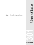
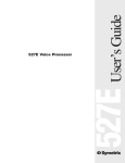
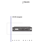
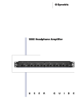
Users Guide 306 306 Preamp/Ducker Table of Contents 1 Chapter 2 Operator Safety Summary 2 Chapter 3 Fast Setup 3 Chapter 4 Front Panel Overview 4 Chapter 5 Rear Panel Overview 6 Chapter 6 Applications 7 Chapter 7 Troubleshooting 9 Chapter 8 Specifications 11 Chapter 9 Block Diagram 12 Chapter 10 Warranty and Service 13 Chapter 11 Declaration of Conformity 15 306 Chapter 1 Introduction Rev A, 30 April, 1999 Symetrix part number 53306-0A00 Subject to change without notice. ©1999, Symetrix, Inc. All right reserved. Symetrix is a registered trademark of Symetrix, Inc. Mention of third-party products is for informational purposes only and constitutes neither an endorsement nor a recommendation. Symetrix assumes no responsibility with regard to the performance or use of these products. Under copyright laws, no part of this manual may be reproduced or transmitted in any form or by any means, electronic or mechanical, including photocopying, scanning, recording or by any information storage and retrieval system, without permission, in writing, from Symetrix, Inc. i 14926 35th Ave. West Lynnwood, WA 98037 USA Tel (425) 787-3222 Fax (425) 787-3211 Email: [email protected] Chapter 1 Introduction Congratulations on your purchase of the Symetrix 306 Preamp/Ducker. Like the other units in the Symetrix 300 series, the 306 is designed to provide extremely versatile controls within a streamlined, half-rack sized housing. Once installed in a paging/foreground music system, the 306 offers precise adjustments to automatically reduce the gain of a program signal when paging occurs. This allows the page to be heard clearly, without having to compete with program material such as audio from a CD, radio, TV or other sources. The Symetrix 306 has a selectable mic/line page input, with phantom power available for condenser microphones. When the mic switch position is selected, preamplification is applied to the page microphone signal to bring it up to line level. A line-level, direct page output is also provided by the 306, for added flexibility. The left and right program inputs and mix outputs of the 306 allow for mono or stereo operation. Front panel controls tailor the amount and duration of ducking, balance the mix between page and program signals, and provide overall volume control. Phone: (425) 787-3222 Fax: (425) 787-3211 Email: [email protected] Website: www.symetrixaudio.com DUCKER PREAMP/ DUCKER OUTPUT THRESHOLD (dBv) DEPTH (dB) HOLD RELEASE -20 -30 2 Sec 2 Sec 306 306 We recommend that you read this guide cover-to cover. You will find the answer to most of your questions inside. If you have technical questions beyond the scope of this manual, please contact our Customer Service Department at: MIX GAIN (dB) 0 DUCK CLIP -40 0 -60 BYPASS .25 Sec 4 Sec .5 Sec 4 Sec PAGE PROGRAM -20 +20 PWR MANUFACTURED BY SYMETRIX INC., LYNNWOOD WA, USA. THIS PRODUCT CONTAINS NO USER SERVICABLE PARTS. PAGE DIRECT OUT MIX OUTPUTS RIGHT PROGRAM INPUTS LEFT RIGHT PAGE INPUT POWER INPUT ON MIC CONNECT TO SYMETRIX PS-3 OR PS-3E POWER SUPPLY ONLY. POWER SUPPLY ONLY. FABRIQUÉ AUX E.-U. PAR SYMETRIX INC., LYNNWOOD, WA, USA. RÉFÉREZ TOUTE RÉPARATION À UN TECHNICIEN QUALIFIÉ. PHANTOM LEFT RIGHT RIGHT OFF LINE MIC/LINE 306 PREAMP/DUCKER Front panel Rear panel 1 Operator Safety Summary Equipment Markings CAUTION RISK OF ELECTRIC SHOCK DO NOT OPEN TO REDUCE THE RISK OF FIRE OR SHOCK DO NOT EXPOSE WARNING: ELECTRIC THIS EQUIPMENT TO RAIN OR MOISTURE DE CHOC ELECTRIQUE AVIS: RISQUE NE PAS OUVRIR SEE OWNERS MANUAL. VOIR CAHIER D’INSTRUCTIONS. No user serviceable parts inside. Refer servicing to qualified service personnel. Il ne se trouve a l’interieur aucune piece pourvant entre reparée l’usager. S’adresser a un reparateur compétent. The lightning flash with arrowhead symbol within an equilateral triangle is intended to alert the user of the presence of uninsulated dangerous voltage within the products enclosure that may be of sufficient magnitude to constitute a risk of electric shock to persons. The exclamation point within an equilateral triangle is intended to alert the user of the presence of important operating and maintenance (servicing) instructions in the literature accompanying the product (i.e. this manual). Caution To prevent electric shock, do not use the Terms polarized plug supplied with the unit with any extension cord, receptacle, or other outlet unless the blades can be fully inserted. Several notational conventions are used in this manual. Some paragraphs may use Note, Caution, or Warning as a heading. Certain typefaces and capitalization are used to identify certain words. These are: 306 Note Caution Warning CAPITALS Boldface 2 Identifies information that needs extra emphasis. A Note generally supplies extra information to help you to better use the 306. Identifies information that, if not heeded, may cause damage to the 306 or other equipment in your system. Identifies information that, if ignored, may be hazardous to your health or that of others. Controls, switches or other markings on the 306s chassis. Strong emphasis. Chapter 2 Important Safety Instructions Please read and keep these instructions. Heed and follow all warnings and instructions. Install in accordance with the manufacturers instructions. Power Source This product is intended to operate from a Symetrix PS-3 or PS-3E power supply. Grounding The chassis of this product is grounded through the grounding conductor of the PS-3 or PS-3E power cord. To avoid electric shock, plug the power cord into a properly wired receptacle before making any connections to the product. A protective ground connection, by way of the grounding conductor in the power cord, is essential for safe operation. Do not defeat the safety purpose of the grounding plug. The grounding plug has two blades and a third grounding prong. The third prong is provided for your safety. When the provided plug does not fit your outlet, consult an electrician for replacement of the obsolete outlet. Danger from Loss of Ground If the protective ground connection is lost, all accessible conductive parts, including knobs and controls that may appear to be insulated, can render an electric shock. Proper Power Cord Use only the power cord and connector specified for the product and your operating locale. Use only a cord that is in good condition. Protect the power cord from being walked on or pinched, particularly at the plug, convenience receptacle, and the point where the cord exits from the apparatus. Operating Locatio. Do not operate this equipment under any of the following conditions: explosive atmospheres, in wet locations, in inclement weather, improper or unknown AC mains voltage, or if improperly fused. Do not install near any heat source such as radiators, heat registers, stoves, or other apparatus (including amplifiers) that produce heat. Unplug this apparatus during lightning storms or when unused for long periods of time. Stay Out of the Box To avoid personal injury (or worse), do not remove the product covers or panels. Do not operate the product without the covers and panels properly installed. Only use accessories specified by the manufacturer. Clean only with a damp cloth. User-serviceable parts There are no user serviceable parts inside the 306. In case of failure, refer all servicing to the factory. Servicing is required when the 306 has been damaged in any way, such as when a power supply cord or plug is damaged, liquid has been spilled or objects have fallen into the apparatus, the apparatus has been exposed to rain or moisture, does not operate normally, or has been dropped. Chapter 3 Fast Setup Fast First-Time Setup Set the THRESHOLD control to the 9:00 position. Set the DEPTH control to the 12:00 position. Set the HOLD and RELEASE controls to the 9:00 position. Set the MIX control to the 12:00 position. Set the GAIN control completely counterclockwise. Connect the 306 to an appropriate source of AC power, using the Symetrix PS-3 or PS-3E power supply provided with your 306. Set the PHANTOM POWER and MIC/LINE switches (located on the back panel) to the correct positions. Connect your audio inputs and outputs. Turn up the GAIN control until the desired volume level is reached. Now read the rest of this manual 306 This section provides simple instructions to begin using the 306. Please refer to later chapters for detailed descriptions of product features and applications. 3 Front Panel Overview Chapter 4 DUCKER DEPTH (dB) HOLD RELEASE -20 -30 2 Sec 2 Sec 306 PREAMP/ DUCKER OUTPUT THRESHOLD (dBv) MIX GAIN (dB) 0 DUCK CLIP -40 0 -60 BYPASS .25 Sec 4 Sec .5 Sec 4 Sec PAGE PROGRAM -20 +20 PWR Ducker Controls DUCK LED This LED lights to indicate that the page signal has exceeded the ducker threshold (see THRESHOLD, below), and ducking of the program material is occurring. THRESHOLD This control adjusts the sensitivity of the ducker circuitry to signals at the page input. Turning this control counterclockwise causes the ducker to be very responsive to a wide dynamic range of page signals. This can be desirable if you want the ducker to react to page signals that range from very quiet to very loud. Turning the THRESHOLD control clockwise causes the ducker to only react to higher-level page signals. This can be useful in preventing unwanted, lower-level signals from triggering the ducker. DEPTH The DEPTH control governs the amount by which the program material will be decreased (ducked) when the duckers threshold has been exceeded. Maximum ducking occurs when this control is set counterclockwise. The program material will then be ducked by 60dB (virtually muted) whenever the signal at the page input exceeds the duckers threshold. As the DEPTH control is turned clockwise, the amount of ducking that occurs when the ducker has been triggered decreases. When the DEPTH control is completely clockwise (bypass), no ducking will occur, even when the duckers threshold has been exceeded. HOLD This control determines the amount of time that ducking will continue at the level determined by the DEPTH control, once the page signal has dropped back below the ducking threshold. As this control is turned clockwise, the hold time is increased. This causes the program material to be ducked for a longer amount of time before the ducker releases and allows the program signal to return to normal. Turning the control counterclockwise creates a shorter hold time, which causes the ducker to release more quickly. Longer hold times contribute to overall smoothness, whereas shorter hold times allow the program level to return to normal more quickly. 306 RELEASE The RELEASE control determines the amount of time that it will take for the program material to be restored to its original (unducked) level once the hold time has passed. Setting this control clockwise causes a longer, smoother return to normal program Threshold Level level. Setting this control Page counterclockwise allows Input the program level to Level recover more swiftly after a page. Long release times Hold Time Duck Level also contribute to an (Depth Control) overall smooth sound, and shorter release times allow for a swifter return to normal program levels. 4 Program Output Level Release Time Output Controls MIX This control sets the relative volume levels of the page signal and the program material. If the page signal is coming through too softly relative to the program material, turn this control counterclockwise until the desired balance is achieved. If the page signal is too loud compared to the program material, turn this control clockwise until the desired balance is achieved. CLIP LED This LED is a warning light, which illuminates just before clipping (distortion) occurs in the output stage of the 306. This LED should never light, or should only flash occasionally (on peaks in the program material or page signal). If the CLIP LED stays on, turn the GAIN control counterclockwise until the LED extinguishes. GAIN (dB) The GAIN control is the final volume adjustment. Once you have achieved the desired balance between page signal and program material, use the GAIN control to determine the overall output level of the 306. Turning this control clockwise increases the volume, and turning this control counterclockwise decreases the volume. To neither add nor subtract gain at this stage, set the GAIN control to the 12 oclock position (the unity gain position for this control). 306 POWER LED This LED lights to indicate the presence of power at the POWER INPUT receptacle on the rear of the 306. 5 MANUFACTURED BY SYMETRIX INC., LYNNWOOD WA, USA. THIS PRODUCT CONTAINS NO USER SERVICABLE PARTS. PAGE DIRECT OUT MIX OUTPUTS RIGHT Chapter 5 PROGRAM INPUTS LEFT RIGHT PAGE INPUT PHANTOM LEFT POWER INPUT ON MIC CONNECT TO SYMETRIX PS-3 OR PS-3E POWER SUPPLY ONLY. POWER SUPPLY ONLY. RIGHT FABRIQUÉ AUX E.-U. PAR SYMETRIX INC., LYNNWOOD, WA, USA. RÉFÉREZ TOUTE RÉPARATION À UN TECHNICIEN QUALIFIÉ. OFF LINE MIC/LINE RIGHT 306 PREAMP/DUCKER Rear Panel Overview POWER INPUT This is a 7-pin DIN power receptacle. Connect only the Symetrix PS-3 (120V power supply), Symetrix PS-3E (230V power supply) or Symetrix PS-3Y (power supply splitting cable for powering two Symetrix units) to the POWER INPUT receptacle. Connect the AC power connector of the PS-3 or PS-3E to an AC power source that is of the correct voltage and frequency, as marked on the PS-3 or PS-3E. PAGE DIRECT OUT This Euroblock terminal connector provides a line-level balanced output of page signal only (no program material). The balanced output terminal pins are ground, low (-) and high (+). For unbalanced operation, use the high (+) and ground terminal pins. Do not ground the low (-) terminal pin. This output may be used to feed paging signal to another paging system. MIX OUTPUT (RIGHT) This output contains paging signal combined with the right channel of the program material, in the proportions determined by the setting of the MIX control on the front panel of the 306. This line-level output is available at the RIGHT MIX OUTPUT Euroblock terminal connector (balanced) and at the RIGHT MIX OUTPUT RCA connector (unbalanced). MIX OUTPUT (LEFT) This output contains paging signal combined with the left channel of the program material, in the proportions determined by the setting of the MIX control on the front panel of the 306. This line-level output is available at the LEFT MIX OUTPUT Euroblock terminal connector (balanced) and at the LEFT MIX OUTPUT RCA connector (unbalanced). PROGRAM INPUTS (RIGHT) Connect the right channel of your line-level program source (signal to be ducked) to either the RIGHT PROGRAM INPUT Euroblock connector (balanced) or the RIGHT PROGRAM INPUT RCA connector (unbalanced). PROGRAM INPUTS (LEFT) Connect the left channel of your line-level program source (signal to be ducked) to either the LEFT PROGRAM INPUT Euroblock connector (balanced) or the LEFT PROGRAM INPUT RCA connector (unbalanced). PAGE INPUT Connect the paging source (the signal that will cause ducking of program material) to this XLR balanced input. The XLR connector is wired Pin 1 ground, Pin 2 high (+) and Pin 3 low (-). Be sure to set the PHANTOM and MIC/LINE switches to the appropriate positions. 306 PHANTOM switch Set this switch to the out (off) position unless your paging source is a condenser microphone which requires phantom power. If your paging source is a condenser microphone which requires phantom power, set this switch to the in (on) position. MANUFACTURED BY SYMETRIX INC., LYNNWOOD WA, USA. THIS PRODUCT CONTAINS NO USER SERVICABLE PARTS. PAGE DIRECT OUT MIX OUTPUTS RIGHT RIGHT PAGE INPUT PHANTOM LEFT ON MIC CONNECT TO SYMETRIX PS-3 OR PS-3E POWER SUPPLY ONLY. POWER SUPPLY ONLY. FABRIQUÉ AUX E.-U. PAR SYMETRIX INC., LYNNWOOD, WA, USA. RÉFÉREZ TOUTE RÉPARATION À UN TECHNICIEN QUALIFIÉ. TO PAGE INPUT (LINE LEVEL) OF ANOTHER 306 HOUSE SOUND SYSTEM 6 PROGRAM INPUTS LEFT POWER INPUT RIGHT RIGHT OFF LINE MIC/LINE 306 PREAMP/DUCKER MIC/LINE switch Set this switch to the line position if your paging source is a line-level source, such as the output of a mic preamp. If your paging source is a mic-level source, such as the output of a microphone, set this switch to the mic position to engage the 306s microphone preamp. EITHER TYPE CONNECTION CAN BE USED PROGRAM SOURCE (SIGNAL THAT WILL BE DUCKED) PAGE MICROPHONE Chapter 6 Applications Foreground Music with Paging DUCKER DEPTH (dB) HOLD RELEASE -20 -30 2 Sec 2 Sec 306 PREAMP/ DUCKER OUTPUT THRESHOLD (dBv) MIX GAIN (dB) 0 DUCK CLIP -40 0 -60 BYPASS .25 Sec 4 Sec .5 Sec PAGE 4 Sec -20 PROGRAM +20 PWR This type of paging system is typically used in a restaurant or shopping mall. In these venues the pages should be clearly heard, but the transition between paging and music should not be too obtrusive. In this case, we recommend that you duck the background music by 10 20dB, and use a longer RELEASE setting to create a smooth transition from paging back into music. Also, you should set the threshold low enough to engage the ducker when a page is made, but high enough that the ducker is not falsely triggered by ambient noise present at the page mic. Foreground Music/Paging with Emergency Override DUCKER DEPTH (dB) HOLD RELEASE -20 -30 2 Sec 2 Sec 306 PREAMP/ DUCKER OUTPUT THRESHOLD (dBv) MIX GAIN (dB) 0 DUCK CLIP -40 0 -60 BYPASS .25 Sec 4 Sec .5 Sec PAGE 4 Sec PROGRAM -20 +20 PWR If you have a foreground music or paging system that you wish to override in the case of an emergency, you will want the ducking action to be swift and thorough. Connect the foreground music source or line-level paging system output to the PROGRAM INPUT(S) of the 306. Connect the emergency paging source to the PAGE INPUT and set the MIC/LINE switch to the appropriate position. Use a low threshold setting for increased sensitivity, and set the DEPTH control completely counterclockwise for maximum ducking. We also recommend long HOLD and RELEASE settings to prevent the program material from returning too quickly. MIX OUTPUTS RIGHT PROGRAM INPUTS LEFT RIGHT PAGE INPUT PHANTOM LEFT ON MIC CONNECT TO SYMETRIX PS-3 OR PS-3E POWER SUPPLY ONLY. POWER SUPPLY ONLY. FABRIQUÉ AUX E.-U. PAR SYMETRIX INC., LYNNWOOD, WA, USA. RÉFÉREZ TOUTE RÉPARATION À UN TECHNICIEN QUALIFIÉ. RIGHT RIGHT EITHER TYPE CONNECTION CAN BE USED TO PAGE LINE INPUTS ON ANOTHER 306 2ND SOUND SYSTEM PROGRAM SOURCE FOR 2ND ZONE (SIGNAL THAT WILL BE DUCKED) OFF LINE MIC/LINE MANUFACTURED BY SYMETRIX INC., LYNNWOOD WA, USA. THIS PRODUCT CONTAINS NO USER SERVICABLE PARTS. PAGE DIRECT OUT MIX OUTPUTS RIGHT PROGRAM INPUTS LEFT RIGHT PAGE INPUT PHANTOM LEFT POWER INPUT ON MIC CONNECT TO SYMETRIX PS-3 OR PS-3E POWER SUPPLY ONLY. POWER SUPPLY ONLY. FABRIQUÉ AUX E.-U. PAR SYMETRIX INC., LYNNWOOD, WA, USA. RÉFÉREZ TOUTE RÉPARATION À UN TECHNICIEN QUALIFIÉ. RIGHT RIGHT OFF LINE MIC/LINE EITHER TYPE CONNECTION CAN BE USED SET PHANTOM OFF AND MIC/LINE TO LINE MAIN SOUND SYSTEM MAIN PROGRAM SOURCE (SIGNAL THAT WILL BE DUCKED) PAGE MICROPHONE Perhaps your installation requires one type of program material for one area (such as a lobby or concourse), and a second type of program material for another area (such as a lounge), but the same announcements need to be heard in both locations. This would call for two Symetrix 306s. Connect the paging source to the PAGE INPUT of the first 306, taking care to set the MIC/LINE switch to the appropriate position. Then connect the desired program source to the Program Inputs of the first 306. Using a short balanced, shielded cable, connect the PAGE DIRECT OUT of the first 306 to the PAGE INPUT of the second 306. Set the MIC/LINE switch on the second 306 to the line position, and connect the appropriate program source to the PROGRAM INPUTS of the second 306. 7 306 PAGE DIRECT OUT POWER INPUT 306 PREAMP/DUCKER MANUFACTURED BY SYMETRIX INC., LYNNWOOD WA, USA. THIS PRODUCT CONTAINS NO USER SERVICABLE PARTS. 306 PREAMP/DUCKER Paging in Multiple Paging Zones To Duck or Mute Program Material without Passing Page Audio DUCKER DEPTH (dB) HOLD RELEASE -20 -30 2 Sec 2 Sec 306 PREAMP/ DUCKER OUTPUT THRESHOLD (dBv) MIX GAIN (dB) 0 DUCK CLIP -40 0 -60 BYPASS .25 Sec 4 Sec .5 Sec 4 Sec PAGE PROGRAM -20 +20 PWR Perhaps you have a small, localized sound system that needs to be ducked when a page on a separate paging system occurs, but you dont want the page audio to appear at the outputs of the localized sound system. An example of this might be a museum exhibit, which has its own localized sound system that needs to be ducked when a page occurs on the larger, museum-wide paging system. Connect the page signal from the separate paging system to the PAGE INPUT of the 306. Set the MIX control completely clockwise (toward Program) and the page audio will cause ducking, but will not pass to the outputs of the 306. Adjust the amount of ducking with the Depth control. Another example of this type of use may be seen when visiting a certain family-oriented pizza restaurant chain. These restaurants feature a 15-minute animated show at the top of the hour, every hour, and the rest of the time background music is played. The animated show has its own sound system, to focus attention on the show, and the background music needs to be muted when the animated show occurs. In this instance, you would connect the background music to the PROGRAM INPUTS of the 306. Then, connect an audio feed from the animated show to the PAGE INPUT of the 306, making sure to set the MIC/LINE switch to the proper position. Set the DEPTH control completely counterclockwise, and set the MIX control completely clockwise. 306 This type of system is also used in some large airports. Each gate has its own small, localized paging system, on which flights arriving and leaving at that gate are announced, and on which background music may be played. A larger, separate paging system services the entire airport. To mute the small sound systems at each gate when an announcement is made on the larger, airportwide paging system, connect a line-level local paging signal to the PROGRAM INPUT(S) of the 306. Connect an audio feed from the larger, airport-wide paging system to the 306s PAGE INPUT, taking care to set the MIC/LINE switch to the correct position. Then, set the DEPTH control completely counterclockwise, and set the MIX control completely clockwise. 8 Chapter 7 Troubleshooting The power LED does not light: Are you using the correct Symetrix power supply for your location? For areas with 120V AC power, the Symetrix PS-3 is correct. For locales with 230V AC power, the Symetrix PS-3E is the correct power supply. Check the power supply connections at the 306 and at the AC power source. Is the AC power source actually providing power? If, after checking all of the above, the 306 is not powering up correctly, consult a qualified service technician or the Symetrix factory. There is no output signal: Is the power LED on? If not, see above. Is the Output Gain control set at 0 or higher? Check input and output cables and connections. Determine that there really is signal coming from the paging source and the program material source, and that these signals are reaching the 306. Is the Mic/Line switch on the Page Input set to the correct position for your paging source? If you are connecting a condenser paging mic that does not have its own power supply to the Page Input of the 306, is the Phantom switch set to the in position? Try setting the Mix control to the 12 oclock position. Is the Duck LED lit? If so, try turning the Threshold control clockwise. If the Threshold control is set counterclockwise, the ducker could be triggered by ambient or other random noises present at the page mic. Shorter Hold time and Release time settings may help, also. Distortion in the output signal: Check your signal sources to make sure that the incoming signals are not already distorted before they reach the 306. Check your input signals. Are they overdriving any of the 306s inputs? If so, reduce the incoming signal level. Is the distortion occurring in both the paging signal and in the program material signal? If the distortion is occurring only in the paging signal, check your paging source. If your paging source is line-level, did you set the 306s Mic/Line switch to the out position? If the distortion is occurring only in the program material signal, then you may be feeding the 306 a program signal that is too hot. Are you using the correct Symetrix power supply for your locale (PS-3 for 120V AC power, PS-3E for 230V AC power)? No ducking is occurring: Is the Depth control turned clockwise (bypass)? Try turning this control counterclockwise. Is page signal reaching the 306? Do you hear the page? 9 306 Is the Clip LED on? If it is, turn the Output Gain down. Buzz in the output: Check input and output connector wiring. Check for ground loops between interconnected system equipment. Are all system components on the same AC ground? Noise (hiss): Check input signal levels. The input may be too low in level. If so, boost the incoming signal. Check the setting of the Mic/Line switch for the 306s Page Input. If the incoming page signal is Mic level, make sure that the Mic/Line Switch is set to the in position. If the incoming page signal is Line level, the Mic/Line switch must be set to the out position. Are one or both of the input signals already noisy? Listen up stream from the 306 to determine that you are feeding it clean signals. The 306 doesnt respond properly: 306 Consult a qualified service technician or the Symetrix factory. 10 Chapter 8 Specifications Architects and Engineers Specifications The 306 preamp/ducker shall provide page-over-music capability. The unit shall occupy one-half rack space (1/2U). The page input shall have one female XLR balanced input. The page input shall have a rear-panel pushbutton which shall engage the preamp circuitry to provide a low-impedance microphone input, or bypass the preamp circuitry to provide a high-impedance line input. The page input shall also have a rear-panel pushbutton, which shall apply +15V phantom power to the page input. The preamp/ducker shall have left-channel and right- channel line-level program inputs, accessible by either one stereo pair of unbalanced RCA jacks or one pair of balanced Euroblock detachable terminal connectors. The 306 shall incorporate a priority ducking system. When audio is present at the page input, the signal present at the program inputs shall be ducked. There shall be a threshold control, which determines the minimum level of page audio that will trigger the ducking function. There shall also be a duck LED, which lights to indicate that ducking is occurring. A depth control shall set the amount of ducking that occurs. There shall be a hold control that determines the amount of time that ducking continues, once the page signal has dropped below threshold. A release control shall determine the how quickly program material to return to normal levels, after the hold time. The output section of the 306 shall incorporate a mix control, which determines the ratio of page signal to program signal, and a gain control, which controls the level of signal present at the mix outputs. There shall be a clip LED, which lights to indicate that output distortion is imminent. The 306 shall have left-channel and right-channel line-level outputs, accessible by either one stereo pair of unbalanced RCA jacks or one pair of balanced Euroblock detachable terminal connectors. The 306 shall also have a page direct output, which provides line-level page-only signal. This balanced output shall have one Euroblock detachable terminal connector. Specifications Input/Output Maximum Input Level Program Input Impedance +20dBu Balanced, +20dBu Unbalanced >20k Ohms Balanced, >10k Ohms Unbalanced Input Common Mode rejection >40dB, mic and line inputs Microphone Phantom Power +15V Maximum Output Level +26dBu Balanced (20k Ohm load) +22dBm Balanced (600 Ohm load) Output Impedance 400 Ohms Balanced, 200 Ohms Unbalanced Performance Data Page Frequency Response 50Hz to 15kHz, +0, -1 dB Program Frequency Response 20Hz to 20kHz, +0, -1dB Page Path THD+Noise <.02% (Mic input to direct page output, 150 Ohm source) Program Path THD+Noise <.025% (+4dBu in, +4dBu out, 0dB ducking) Output Gain +/-20dB Connections Page Input Program Inputs Mix Outputs Page Direct Output Power In Physical Size (hwd) Shipping Weight Electrical Power Requirements XLR RCA jacks, Euroblock RCA jacks, Euroblock Euroblock 7 pin DIN ½ rack unit 1.75 x 8.5 x 6.5 in., 4.445 x 21.59 x 15.875 cm. 4.5 lbs 120V nominal, 95 to 130V AC, 50 to 60 Hz, 10 watts 230V nominal, 207 to 253V AC, 50 Hz, 10 watts In the interest of continuous product improvement, Symetrix, Inc. reserves the right to alter, change, or modify these specifications without prior notice. ©1999, Symetrix, Inc. All rights reserved. 11 306 The preamp/ducker shall be a Symetrix, Inc. model 306 Preamp/Ducker. Block Diagram Chapter 9 LEFT BALANCED PROGRAM IN LEFT BALANCED MIX OUT VCA LEFT UNBALANCED PROGRAM IN GAIN LEFT UNBALANCED MIX OUT RIGHT BALANCED PROGRAM IN MIX RIGHT BALANCED MIX OUT VCA RIGHT UNBALANCED PROGRAM IN DUCK RIGHT UNBALANCED MIX OUT THRESHOLD DEPTH HOLD CONTROL VOLTAGE CIRCUITRY CLIP RELEASE DIRECT PAGE OUTPUT PAGE INPUT PHANTOM 306 +V 12 MIC/LINE Chapter 10 Warranty & Service 306 Limited Warranty Symetrix, Inc. expressly warrants that the product will be free from defects in material and workmanship for one (1) year. Symetrix's obligations under this warranty will be limited to repairing or replacing, at Symetrix's option, the part or parts of the product which prove defective in material or workmanship within one (1) year from date of purchase, provided that the Buyer gives Symetrix prompt notice of any defect or failure and satisfactory proof thereof. Products may be returned by Buyer only after a Return Authorization number (RA) has been obtained from Symetrix. Buyer will prepay all freight charges to return the product to the Symetrix factory. Symetrix reserves the right to inspect any products which may be the subject of any warranty claim before repair or replacement is carried out. Symetrix may, at its option, require proof of the original date of purchase (dated copy of original retail dealer's invoice). Final determination of warranty coverage lies solely with Symetrix. Products repaired under warranty will be returned freight prepaid by Symetrix via United Parcel Service (surface), to any location within the Continental United States. At Buyer's request the shipment may be returned via airfreight at Buyer's expense. Outside the Continental United States, products will be returned freight collect. The foregoing warranties are in lieu of all other warranties, whether oral, written, express, implied or statutory. Symetrix, Inc. expressly disclaims any IMPLIED warranties, including fitness for a particular purpose or merchantability. Symetrix's warranty obligation and buyer's remedies hereunder are SOLELY and exclusively as stated herein. This Symetrix product is designed and manufactured for use in professional and studio audio systems and is not intended for other usage. With respect to products purchased by consumers for personal, family, or household use, Symetrix expressly disclaims all implied warranties, including but not limited to warranties of merchantability and fitness for a particular purpose. This limited warranty, with all terms, conditions and disclaimers set forth herein, shall extend to the original purchaser and anyone who purchases the product within the specified warranty period. Symetrix does not authorize any third party, including any dealer or sales representative, to assume any liability or make any additional warranties or representation regarding this product information on behalf of Symetrix. This limited warranty gives the buyer certain rights. You may have additional rights provided by applicable law. Limitation of Liability The total liability of Symetrix on any claim, whether in contract, tort (including negligence) or otherwise arising out of, connected with, or resulting from the manufacture, sale, delivery, resale, repair, replacement or use of any product will not exceed the price allocable to the product or any part thereof which gives rise to the claim. In no event will Symetrix be liable for any incidental or consequential damages including but not limited to damage for loss of revenue, cost of capital, claims of customers for service interruptions or failure to supply, and costs and expenses incurred in connection with labor, overhead, transportation, installation or removal of products or substitute facilities or supply houses. 13 306 Warranty Registration must be completed and mailed to Symetrix within thirty (30) days of the date of purchase. Servicing the 306 If you have determined that your 306 requires repair services and you live outside of the United States, please contact your local Symetrix dealer or distributor for instructions on how to obtain service. If you reside in the U.S. then proceed as follows: Before sending anything to Symetrix, contact our Customer Service Department for a return authorization (RA) number. The telephone number is (425) 787-3222, Monday through Friday, 8AM (0800 hours) though 4:30 PM (1630 hours) Pacific Time. At the Symetrix factory, Symetrix will perform in-warranty or out-of-warranty service on any product it has manufactured for a period of five years from date of manufacture. In-warranty Repairs To get your 306 repaired under the terms of the warranty: 1. Call us for an RA number. 2. Pack the unit in its original packaging materials. 3. Include your name, address, daytime telephone number, and a brief statement of the problem. 4. Write the RA number on the outside of the box. 5. Ship the unit to Symetrix, freight prepaid. We do not accept freight collect shipments. Repairs made in-warranty will cost you only one-way freight charges. Well prepay the return (surface) freight. 306 If you send us your product in substandard packaging, we will charge you for factory shipping materials. If you dont have the factory packaging materials, please use an oversized carton, wrap the unit in a plastic bag, and surround it with bubble-wrap. Pack the box full of Styrofoam peanuts. Be sure there is enough clearance in the carton to protect the rack ears (you wouldnt believe how many units are returned with bent ears). We will return the unit in Symetrix packaging. Of course, if the repair is due to operator error, parts and labor will be charged. In any event, if there are charges for the repair costs, you will pay for the return freight. All charges will be COD unless you have made other arrangements (prepaid, Visa or Mastercard). Out-of-warranty Repairs If the warranty period has passed, youll be billed for all necessary parts, labor, packaging materials, and freight charges. Please remember, you must call for an RA number before sending the unit to Symetrix. 14 Chapter 11 Declaration of Conformity Declaration of Conformity We, Symetrix Incorporated, 14926 35th Ave. West, Lynnwood, Washington, USA, declare under our sole responsibility that the product: 306 Preamp/Ducker to which this declaration relates, is in conformity with the following standards: EN 60065 Safety requirements for mains operated electronic and related apparatus for household and similar general use. EN 55103-1 Electromagnetic compatibility - Generic emission standard Part 1: Residential, commercial, and light industry. EN 55103-2 Electromagnetic compatibility - Generic immunity standard Part 1: Residential, commercial, and light industry. The technical construction file is maintained at: Symetrix, Inc. 14926 35th Ave. West Lynnwood, WA, 98037-2303 USA 306 The authorized representative located within the European Community is: World Marketing Associates P.O. Box 100 St. Austell, Cornwall, PL26 6YU, U.K. Date of issue: April 30, 1999 Place of issue: Lynnwood, Washington, USA Authorized signature: Dane Butcher, President, Symetrix Incorporated. 15 306 16 Symetrix, Inc. 14926 35th Ave. West Lynnwood, WA, 98037-2303 USA Tel: (425) 787-3222 Fax: (425) 787-3211 Website: http://www.symetrixaudio.com Email: [email protected]