1
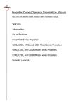
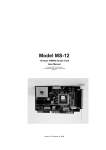
SERVICE LETTER
SL1995-4C
March 13, 2013
TITLE
FIELD INSPECTION AND REPAIR OF PROPELLER BLADES
MODELS AFFECTED
All "Threaded" C1 through C98 Propeller Models
NOTE: For McCauley fixed pitch propellers and C201 through C1105 model series propellers, refer to the
MPC26 Revision 2 (or latest revision) for field inspection and repair of propeller blades.
PUBLICATIONS AFFECTED
720415, Constant Speed Service Manual (Threaded Propellers)
710930, Full Feathering Service Manual (Threaded Propellers)
BOM100, Blade Overhaul Manual
REASON
Reports from the field indicate questions concerning repair of damage found on blades during inspection
(e.g. preflight, 100 hour, and annual inspection).
This service information is to remain active indefinitely.
Stress risers can cause failure of a blade if not repaired.
A stress riser is an increase in stress intensity surrounding an area of reduced cross-sectional area. A sharp
stress riser is an increased stress intensity attributed to a notch-like displacement of material resulting from a
sharp object impact, leaving a very small radius at the bottom of the displaced material (see Figure 1).
NOTE: Sometimes a stress riser in the propeller may be referred to as a nick.
Stress riser damage found during a routine inspection must be field repaired if it is not beyond the field repair
limits. If damage is beyond the field repair limits, the blade must be evaluated and/or replaced by an FAA
approved Part 145 Propeller Repair Station or international equivalent. Stress risers may be caused by sharp,
hard objects striking the rotating blade, or can develop from corrosion such as exfoliation or intergranular
type corrosion.
Blade erosion is the abrading of surface material attributed to impact with small particles such as sand, dirt,
and water. Small object impact typically does not cause sharp bottom radiuses and therefore do not result
in sharp stress risers or significant material displacement that elevate the stress intensity to a level which
cause crack initiation. Erosion of the blade surface that does not result in stress risers, does not require field
repair of the damaged surface.
If corrosion is observed on the propeller, clean the affected area of the propeller and chemical conversion film
coat, and if applicable, touch up the paint in accordance with this service letter.
If erosion is repaired, corrosion protect the propeller blade in the area of the repair. Chemical conversion film
coat the repaired area and then touch up the propeller paint in accordance with this service letter.
Service Letter 1995-4C replaces Service Letter 1995-4B. Service Letter 1995-4C does not apply to the
114HCA, L114HCA and 96LRB blades which are shotpeened. Lines in margin indicate technical changes.
Original Issue: February 10, 1995
Page 1 of 13
TO OBTAIN SATISFACTORY RESULTS, PROCEDURES SPECIFIED IN THIS SERVICE INFORMATION MUST BE ACCOMPLISHED IN
ACCORDANCE WITH ACCEPTED METHODS AND PREVAILING GOVERNMENT REGULATIONS. MCCAULEY PROPELLER SYSTEMS
CANNOT BE RESPONSIBLE FOR THE QUALITY OF WORK PERFORMED IN ACCOMPLISHING THIS SERVICE INFORMATION.
McCauley Propeller Systems
PO Box 7704
Wichita, Kansas 67277-7704
COPYRIGHT © 1995 McCauley Propeller Systems
SERVICE LETTER
SL1995-4C
COMPLIANCE
At any inspection (preflight, 100 hour, or annual) at which damage is noted.
APPROVAL
FAA approval has been obtained on technical data in this publication that affects type design.
ACCOMPLISHMENT INSTRUCTIONS
1.
Instructions
CAUTION: DO NOT USE A RASP FILE FOR FIELD REPAIRS. RASP-TYPE FILES REMOVE
MORE METAL THAN NECESSARY AND MAY CAUSE PREMATURE REJECTION
OF THE BLADE AT OVERHAUL.
A.
Give close attention to deice boots during visual inspection. Boot damage may have penetrated the
boot heating element and damaged the blade.
NOTE: Do not assume deice boot is not damaged if it is heating normally.
(1)
Remove boot and inspect blade if this type of damage is suspected.
(a)
(2)
2.
Refer to the applicable aircraft service or maintenance manual for deice boot removal
instructions.
Small object damage is normally found on the leading edge and face side of the propeller
blade. Damage will normally occur on reversing propellers on the camber side at the outboard
stations.
Repair Criteria
A.
Removal of Blade Damage
(1)
General
(a)
The propeller blade is a highly stressed part. The fact that propeller blades are subject to
impact damage, (such as nicks, gouges, and scratches), and corrosion, (primarily uniform
etch and pitting corrosion, but intergranular or exfoliation type corrosion can also occur)
demands frequent inspection and maintenance.
(b)
Repair of small nicks, gouges and scratches that do not exceed the damage specifications
identified in this section, Blade Repair are considered "Minor Repairs" and may be
performed by an appropriated rated mechanic or repair station. After filing and polishing,
the damaged area should be inspected, and when possible, by fluorescent dye penetrant
method to verify that all damage has been removed and the blade is not cracked. The
area should then be re-protected by localized application of chemical film per MIL-C-5541
(for example, Alodine) and repainted as necessary.
NOTE: Refer to the fluorescent dye penetrant inspection procedures in this service letter
as required.
NOTE: If it is not possible to inspect the repaired area using the fluorescent dye
penetrant inspection method, the repaired region should be visually inspected
with a minimum 10x power lens to ensure any sharp notches or cracks have
been removed.
(c)
Page 2
All other damage that exceeds the damage specifications identified in this service
letter, or other damage such as bent blades, are considered "Major Repairs" and must
be corrected by an FAA approved Part 145 Propeller Repair Station or international
equivalent and are not field repairable.
SL1995-4C
March 13, 2013
SERVICE LETTER
SL1995-4C
(2)
Damage Specifications
(a)
The depth of damage must be measured using a depth gage.
(b)
Damage that is located on the leading or trailing edges must not exceed 0.094 inch
(2.39 mm) in depth.
(c)
Damage that is located on a repairable area of the face or camber side of the blade must
not exceed 0.061 inch (1.55 mm) in depth.
1
For controllable pitch propellers:
Impact and corrosion damage that is located at least 6.0 inches (152 mm) from
the hub socket is in an area that is field repairable.
(d)
(3)
Damage that is located outside the field repairable area or damage depth greater than
these limits is not field repairable. An FAA approved Part 145 Propeller Repair Station or
international equivalent may be able to do a repair. Contact McCauley Product Support
for disposition of any damage that is deeper than the specified limits.
Repairable Damage
(a)
The primary type of blade damage that a mechanic needs to be concerned with is sharp
stress riser type damage. This type of damage is caused by stones or other small objects
striking the propeller blade as it rotates. Erosion caused by sand, water, etc. that does
not create sharp stress riser type damage does not need to be repaired in the field.
CAUTION: THE USE OF A RASP FILE IS NOT RECOMMENDED FOR FIELD
REPAIRS. RASP-TYPE FILES WILL REMOVE MORE METAL THAN
NECESSARY, AND MAY CAUSE PREMATURE REJECTION OF THE
BLADE AT PROPELLER OVERHAUL.
NOTE: If the propeller blade has erosion damage and there are no signs of corrosion,
no further action is required. However, it is recommended that erosion damage
be protected from corrosion with a chemical conversion film coat (for example,
Alodine) and then touch up the propeller paint in accordance with the instructions
in this service letter.
(b)
Give close attention to deice boots during the visual inspection. Boot damage may have
penetrated the boot heating element and damaged the blade. Remove the boot and
inspect the propeller blade if this type of damage is suspected.
NOTE: Do not assume the deice boot (if installed) is not damaged if it is heating normally.
1
(c)
Small object damage is normally found on the leading edge and face side of the
propeller blade. Damage will normally occur on reversing propellers on the camber
side at the outboard stations.
It is very important that stress riser type damage be completely repaired. When filing the
damaged area is complete, a fluorescent dye penetrant examination of the affected area
should be performed, when possible, to verify that the stress riser has been completely
removed.
NOTE: If it is not possible to inspect the repaired area using the fluorescent dye
penetrant inspection method, the repaired region should be visually inspected
with a minimum 10x power lens to ensure any sharp notches or cracks have
been removed.
SL1995-4C
March 13, 2013
1
A stress riser can cause the failure of a propeller blade if not repaired properly.
2
A stress riser is an increase in stress intensity surrounding an area of reduced
cross-sectional area. A sharp stress riser is an increased stress intensity attributed
Page 3
SERVICE LETTER
SL1995-4C
to a notch-like displacement of material resulting from a sharp object impact, leaving
a very small radius at the bottom of the displaced material, refer to Figure 1.
NOTE: Sometimes a stress riser in the propeller may be referred to as a nick.
Page 4
SL1995-4C
March 13, 2013
SERVICE LETTER
SL1995-4C
Figure 1. Sharp Stress Riser (Sheet 1)
SL1995-4C
March 13, 2013
Page 5
SERVICE LETTER
SL1995-4C
3
Stress riser damage found during a routine inspection must be field repaired if it
is not beyond the field repair limits. If the damage appears to be beyond the field
repair limits, the blade must be evaluated and/or replaced by an FAA approved
Part 145 Propeller Repair Station or international equivalent. Stress risers may
be caused by sharp, hard objects striking the rotating blade, or can develop from
corrosion such as exfoliation or intergranular type corrosion.
4
Blade erosion is the abrading of surface material attributed to impact with small
particles such as sand, dirt, and water. Small object impact typically does not cause
sharp bottom radiuses and therefore do not result in sharp stress risers or significant
material displacement that elevate the stress intensity to a level which cause crack
initiation. Erosion of the blade surface that does not result in stress risers, does not
require field repair of the damaged surface. If significant material displacement has
occurred, measure the area of the blade with the most erosion damage.
5
•
Damage that is located on the leading or trailing edges must not exceed 0.094
inch (2.39 mm) in depth. Damage greater than 0.094 inch (2.39 mm) in depth
is not field repairable.
•
Damage that is located on a repairable area of the face or camber side of the
blade must not exceed 0.061 inch (1.55 mm) in depth. Damage greater than
0.061 inch (1.55 mm) in depth is not field repairable.
If corrosion is observed on the propeller:
•
For uniform etch type corrosion, remove the corrosion and clean the affected
area of the propeller and chemical conversion film coat, and if applicable,
touch up the paint in accordance with the instructions in this service letter.
•
For pitting, intergranular or exfoliation type corrosion, remove the corrosion
and examine the affected area for stress riser damage. If stress riser damage
is found, repair the damage. Clean the affected area of the propeller and
chemical conversion film coat, and if applicable, touch up the paint in
accordance with the instructions in this service letter.
NOTE: After the corrosion is removed, measure the damaged area, damage
that is located on the leading or trailing edges must not exceed 0.094
inch (2.39 mm) in depth and damage that is located on a repairable
area of the face or camber side of the blade must not exceed 0.061
inch (1.55 mm) in depth.
6
(4)
Repair Criteria
(a)
Repair stress riser damage. Stress riser damage is repaired by removing adjacent
material from the damaged area so that there is no longer a notch of displaced material
with a very small radius at the bottom of the damaged area. Material is removed with
small smooth cut mill files, emery cloth, and/or sandpaper. When the stress riser removal
is complete, perform a fluorescent dye penetrant inspection to verify that the stress
riser has been completely removed. Refer to the instructions in this service letter for
fluorescent dye penetrant inspection procedures.
(b)
Do not remove more material than what is required to remove the stress riser from the
propeller blade. Unnecessary or excessive propeller blade material removal will cause
premature replacement of the propeller blade at propeller overhaul.
(c)
Leading and Trailing Edge Repair Procedure
1
Page 6
If erosion is repaired, corrosion protect the propeller blade in the area of the repair.
Chemical conversion film coat (for example, Alodine) the repaired area and then
touch up the propeller paint in accordance with the instructions in this service letter.
Determine the depth of the damaged area.
SL1995-4C
March 13, 2013
SERVICE LETTER
SL1995-4C
•
The depth of damage must be measured using a depth gage.
•
Damage that is located on the leading or trailing edges must not exceed 0.094
inch (2.4 mm) in depth.
•
Damage depth greater than this limit is not field repairable.
NOTE: An FAA approved Part 145 Propeller Repair Station or international
equivalent may be able to do a repair. Contact McCauley Product Support
for disposition of any damage that is deeper than the specified limits.
2
Remove metal at the damaged area starting back from and working toward the edge
in such a way that the contour remains substantially the same. File strokes must run
from blade shank to blade tip. Avoid abrupt changes in contour and blunt edges.
3
The length of the blended area shall be equal to 10 times the depth of the damage.
Refer to Figure 2.
4
The finished repair should be the depth of the original damage plus 0.031 inch
(0.8 mm).
5
Initial removal of material should be done using a small smooth cut mill file.
6
All traces of file marks in the repaired area should be removed with number 240
emery cloth or equivalent grit sandpaper.
7
Smooth the repaired area followed by polishing with number 320 emery cloth and
600 grit emery cloth or equivalent grit sandpaper.
NOTE: Do not use sandpaper or emery cloth that contains iron oxide material on
aluminum propellers.
8
Determine the depth of the repaired damaged area.
•
The maximum depth of the damage repair area must be measured using a
depth gage.
•
The repair that is located on the leading or trailing edges must not exceed
0.125 inch (3.2 mm) in depth.
•
Propeller damage depth greater than this limit is not field repairable.
NOTE: An FAA approved Part 145 Propeller Repair Station or international
equivalent may be able to do a repair. Contact McCauley Product Support
for disposition of any damage that is deeper than the specified limits.
(d)
Face And Camber Repair Procedure
1
Determine the depth of the damaged area.
•
The depth of damage must be measured using a depth gage.
•
Damage that is located on the face or camber sides of the propeller must not
exceed 0.061 inch (1.55 mm) in depth.
•
Damage depth greater than this limit is not field repairable.
NOTE: An FAA approved Part 145 Propeller Repair Station or international
equivalent may be able to do a repair. Contact McCauley Product Support
for disposition of any damage that is deeper than the specified limits.
SL1995-4C
March 13, 2013
Page 7
SERVICE LETTER
SL1995-4C
CAUTION: USE EXTREME CARE TO CONTROL THE HAND HELD GRINDER.
2
Remove metal at the damaged area by hand using a coarse grain emery cloth or
by a hand held rotary grinder with 120 or finer grit bob. Do not use a hand file in
this area.
NOTE: Do not use sandpaper or emery cloth that contains iron oxide material on
aluminum propellers.
3
Grind blade with light pressure in a circular motion until damage is totally removed.
The diameter of the repair shall be equal to 20 times the depth of damage. Refer to
Figure 2.
4
The finished repair should be the depth of the original damage plus 0.002 inch
(0.05 mm)
5
Smooth the repaired area with number 240 and 320 emery cloth or equivalent
grit sandpaper.
6
Polish the repaired area with number 600 grit emery cloth or equivalent grit
sandpaper.
NOTE: Do not use sandpaper or emery cloth that contains iron oxide material on
aluminum propellers.
7
Determine the depth of the repaired damaged area.
•
The maximum depth of the damage repair area must be measured using a
depth gage.
•
A repair that is located on the face or camber side of the propeller must not
exceed 0.063 inch (1.6 mm) in depth.
•
Propeller damage depth greater than this limit is not field repairable.
NOTE: An FAA approved Part 145 Propeller Repair Station or international
equivalent may be able to do a repair. Contact McCauley Product Support
for disposition of any damage that is deeper than the specified limits.
(e)
Inspect Repaired Area
1
(f)
(g)
Page 8
Do a fluorescent dye penetrant inspection to verify that the stress riser has been
completely removed. Refer to the instructions in this service letter for fluorescent
dye penetrant inspection procedures.
Blade Painting After Repair
1
Prepare the repaired area for touch up paint by wiping with a Methyl n-Propyl
Ketone (MPK) dampened cloth.
2
Corrosion protect the propeller blade in the area of the repair. Refer to the
instructions in this service letter for the application of a chemical conversion film
coating (for example, Alodine) on the repaired area of the propeller.
3
Touch up the propeller paint in accordance with the procedures in this service letter
to blend the paint with the original finish.
Install Deice Boot (If applicable)
1
If a deice boot was removed as a result of this inspection, install the removed or
replacement deice boot on the propeller blade.
2
Refer to the applicable aircraft service or maintenance manual for deice boot
installation instructions.
SL1995-4C
March 13, 2013
SERVICE LETTER
SL1995-4C
Figure 2. Field Blade Rework Criteria (Sheet 1)
SL1995-4C
March 13, 2013
Page 9
SERVICE LETTER
SL1995-4C
Figure 2. Field Blade Rework Criteria (Sheet 2)
Page 10
SL1995-4C
March 13, 2013
SERVICE LETTER
SL1995-4C
3.
Fluorescent Dye Penetrant Inspection Procedures
A.
General
(1)
Fluorescent penetrant inspection shall be performed as specified in this manual on products
manufactured by McCauley Propeller Systems. Penetrant inspection, for continued
airworthiness, shall be used to detect cracks or discontinuities open to the surface which may
not be evident by direct visual inspection.
(2)
Inspection is performed in accordance with standard ASTM-E-1417 (latest revision), Standard
Practice for Liquid Penetrant Examination. McCauley requires all dye penetrant inspections
to conform to the Type I Fluorescent Dye and with a sensitivity level 3 as described in the
ASTM-E-1417 (latest revision) standard.
NOTE: The use of visible dye penetrants (Type II) is not recommended for the inspection of
the propeller and propeller hardware. While Type II visible dye penetrants do have
limited crack detection capability, the constituents of visible dye penetrants are likely to
deposit residue in crack voids. The residue can be extremely difficult to remove from
cracks, regardless of the cleaning method employed. Cracks can become fully or
partially masked by the remaining residue. Due to these characteristics, visible dye
penetrants can make follow-on detection of existing cracks virtually impossible when
using other NDI penetrant methods, specifically Fluorescent Penetrant Inspection
(FPI). Use of FPI for NDI type inspections on some propellers and propeller hardware
is a requirement at propeller overhaul. Furthermore, visible dye residue contamination
of fluorescent penetrant fluid is also known to significantly reduce the brightness of
fluorescent indication. Visible dye penetrants include AMS2644, Type 2 red dye
penetrant, or any vividly colored dye penetrant visible under ordinary white light.
AMS2644, Type 1, Fluorescent penetrants which are visible under ultraviolet light are
considered different materials by standard practices and should not be considered a
subset of visible dye penetrants.
B.
Personnel
(1)
C.
D.
Acceptance Criteria
(1)
Any verified flaw indications are rejectable.
(2)
Any indication which is believed to be non-relevant shall be regarded as a defect and shall be
reexamined by an FAA approved Part 145 Propeller Repair Station or international equivalent
to verify whether or not actual defects are present.
Post Cleaning
(1)
4.
Individuals performing inspections for continued airworthiness defined in this manual shall hold
an Airframe and Powerplant rating or international equivalent.
Residual penetrant and developer must be removed prior to recoating using a cleaning solvent
or vapor degreasing. Verify complete removal by inspecting under a ultraviolet light.
Chemical Conversion Film Coating
NOTE: All repaired blades must have Chemical Conversion Film Coating applied for corrosion protection.
A.
General
(1)
The process for aluminum components must be in accordance with MIL-DTL-5541 and
MIL-DTL-81706 Class 1A.
(2)
All repairs must be complete before the part is treated.
(3)
All grease, oil, or other material must be removed using solvent and/or a water based cleaner
so the part, or the area of the part to be treated, has a water break free surface as required
by section 3.3.2 of MIL-DTL-5541.
SL1995-4C
March 13, 2013
Page 11
SERVICE LETTER
SL1995-4C
B.
All parts that are chemical conversion film coated must have paint applied except on the engine
mounting flange, cylinder mounting flange, and the area of the hub socket where the shim carrier
contacts the hub.
CAUTION: PAINT OR PRIMER IS NOT ALLOWED ON THE ENGINE MOUNTING FLANGE,
CYLINDER MOUNTING FLANGE, AND THE AREA OF THE HUB SOCKET WHERE
THE SHIM CARRIER CONTACTS THE HUB. THIS IS A 5.295 INCH (134.5 MM)
DIAMETER CIRCLE MEASURED FROM THE CENTER OF ALL BLADE SOCKETS.
5.
Blade Painting
NOTE: McCauley strongly recommends that all blades be painted. Paint and primer protect blades
from corrosion. McCauley recommends Sherwin-Williams products, but any industry equivalent
is acceptable. The following procedure is recommended, but any procedure achieving similar
results is acceptable.
NOTE: Repainting the entire propeller blade or the propeller assembly should only be accomplished at an
FAA approved Part 145 Propeller Repair Station or international equivalent. Without the proper
training and equipment, the static balance of the propeller can be affected by the application of
paint.
NOTE: The propeller face side should be painted flat black unless otherwise noted.
A.
Paint and Primer Mixtures.
NOTE: McCauley recommends Sherwin-Williams products, but any industry equivalent is
acceptable.
NOTE: All drying times are based on 77°F (25°C) and 45% relative humidity.
CAUTION: NO PAINT OR PRIMER IS ALLOWED IN BLADE RETENTION AREA OR THE
COUNTERWEIGHT SURFACE.
(1)
Primer should be tack free in 10 to 20 minutes and can be recoated in 30 to 60 minutes.
(2)
Allow for different drying times at different temperatures and humidity levels.
Paint and Primer Mixtures
Paint/Primer
Primer
Page 12
Mixture Instructions
1 Part Sherwin Williams P60G2 Industrial Wash Primer to 1.5 parts Sherwin
Williams R7K44 Activator/Thinner
Semi-Flat
Black Paint
F63TXB11492
Mix as directed by the manufacturer with V66V27 catalyst and R7K84
reducer (Note 1) Federal Standard 595 Color 37038
Semi-Flat
White Paint
F63TXV11445
Mix as directed by the manufacturer with V66V27 catalyst and R7K84
reducer (Note 1) Federal Standard 595 Color 17875
Semi-Flat
Silver Paint
F63TXS144334302
Mix as directed by the manufacturer with V66V27 catalyst and R7K84
reducer (Note 1)
Semi-Flat
Gray Paint
F63YXA11582
Mix as directed by the manufacturer with V66V27 catalyst and R7K84
reducer (Note 1)
SL1995-4C
March 13, 2013
SERVICE LETTER
SL1995-4C
Paint/Primer
Mixture Instructions
Gloss Yellow Paint
F63BXY11719
Mix as directed by the manufacturer with V66V27 catalyst and R7K84
reducer (Note 1)
Semi-Flat
Red Paint
F63TXR11347
Mix as directed by the manufacturer with V66V27 catalyst and R7K84
reducer (Note 1) Federal Standard 595 Color 31136
NOTE: The color numbers are assigned by the Atlanta, Georgia Sherwin-Williams facility.
B.
The painted surface must be recoated with the first coat of the finish enamel within four hours
of application of the primer.
C.
Apply the paint in accordance with the manufacturer's instructions.
NOTE: Overnight drying time is recommended after paint application.
D.
The recommended dry film paint thickness on constant speed and full feathering propeller blades
should be 3 mils thick.
NOTE: Tip stripes should be painted on the camber side only so as not to interfere with the pilot's
field of vision. Some propellers installed in a pusher configuration (and out of the pilot's field
of view) may have a different paint scheme for the propeller blade tips.
SL1995-4C
March 13, 2013
Page 13