1
MPA-3
Multiparameter Data Acquisition System
User Manual
copyright FAST ComTec GmbH
Grünwalder Weg 28a, D-82041 Oberhaching
Germany
Version 1.87, July 21, 2010
Warranty Information
Warranty Information
FAST ComTec assures that all the data and descriptions in this manual are made to the best of
our knowledge. FAST ComTec is not liable for technical or editorial errors or omissions made
herein. The features and specifications described in this manual are subject to change without
notice.
FAST ComTec warrants proper operation of the software only when used with software and
hardware supplied by FAST ComTec. FAST ComTec assumes no responsibility for modifications
made to this software by third parties, or for the use or reliability of this software if used with
hardware or software not supplied by FAST ComTec. FAST ComTec makes no other warranty,
expressed or implied, as to the merchantability or fitness for an intended purpose of this software.
Software License
You have purchased the license to use this software, not the software itself. Since title to this
software remains with FAST ComTec, you may not sell or transfer this software. This license
allows you to use this software on only one compatible computer at a time. You must get FAST
ComTec's written permission for any exception to this license. A general exception that we grant
here is the offline evaluation of data taken with MPA-3. This is allowed within the working group
on up to 10 seperated computers. The evaluation by replay of list data is restricted and possible
only with the replay licence programmed in the MPA-3 base module or a key module that must be
connected to a parallel port.
Backup Copy
This software is protected by German Copyright Law and by International Copyright Treaties. You
have FAST ComTec's express permission to make one archival copy of this software for backup
protection. You may not otherwise copy this software or any part of it for any other purpose.
Copyright 1998-2010 FAST ComTec Communication Technology GmbH,
D-82041 Oberhaching, Germany. All rights reserved.
This manual contains proprietary information; no part of it may be reproduced by any means
without prior written permission of FAST ComTec, Grünwalder Weg 28a, D-82041 Oberhaching,
Germany. Tel: ++49 89 66518050, FAX: ++49 89 66518040, http://www.fastcomtec.com .
The information in this manual describes the hardware and the software as accurately as
possible, but is subject to change without notice.
ComTec GmbH
II
Important Information on Hardware Compatibility
Important Information on Hardware Compatibility
The MPA-3 Multiparameter Systems are PCI Local Bus compliant devices. As such the board
contains the configuration space register organization as defined by the PCI Local Bus
Specification. Among the functions of the configuration registers is the storage of unique
identification values for our devices as well as storage of base address size requirements for
correct operation specific to each of our products.
The host computer that our products are installed in is responsible for reading and writing to/from
the PCI configuration registers to enable proper operation. This functionality is referred to as 'Plug
and Play' (PnP). As such, the host computer PnP BIOS must be capable of automatically
identifying a PCI compliant device, determining the system resources required by the device, and
assigning the necessary resources to the device. Failure of the host computer to execute any of
these operations will prohibit the use of the MPA-3 systems in such a host computer system.
It has been determined that systems that implement PnP BIOS, and contain only fully compliant
PnP boards and drivers, operate properly. However, systems that do not have a PnP BIOS
installed, or contain hardware or software drivers which are not PnP compatible, may not
successfully execute PnP initialization. This can render the MPA-3 system inoperable. It is
beyond the ability of FAST ComTec's hardware or software to force a non-PnP system to operate
MPA-3 Multiparameter systems.
ComTec GmbH
III
Table of Contents
Table of Contents
1. Introduction .............................................................................................................................. 1-1
2. Installation Procedure .............................................................................................................. 2-1
2.1. Hard- and Software Requirements ............................................................................. 2-1
2.2. Hardware Installation .................................................................................................. 2-1
2.3. Software Installation.................................................................................................... 2-5
2.4. Getting Started with a basic SINGLE measurement................................................... 2-5
2.5. Getting Started with a basic COINCIDENCE measurement .................................... 2-10
2.6. Basic Usage of the RealTimeClock Option............................................................... 2-14
3. Hardware Description .............................................................................................................. 3-1
3.1. Overview ..................................................................................................................... 3-1
3.2. PCI Card ..................................................................................................................... 3-2
3.2.1. General........................................................................................................... 3-2
3.2.2. 'GO' Line Connector ....................................................................................... 3-3
3.2.3. Digital I/O Port ................................................................................................ 3-3
3.2.4. Analog Output ................................................................................................ 3-4
3.2.5. Power Supply ................................................................................................. 3-4
3.2.6. FHS Link......................................................................................................... 3-4
3.2.7. Nonvolatile Memory........................................................................................ 3-4
3.3. BASE Module.............................................................................................................. 3-5
3.3.1. General........................................................................................................... 3-5
3.3.2. Signature PLD ................................................................................................ 3-5
3.3.3. Power Supply ................................................................................................. 3-5
3.3.4. FHS Link......................................................................................................... 3-6
3.3.5. FMP Bus......................................................................................................... 3-6
3.3.6. Indicators........................................................................................................ 3-6
3.3.7. Auxiliary I/O Connectors ................................................................................ 3-7
3.3.8. REJECT Input ................................................................................................ 3-7
3.3.9. 48 bit RealTimeClock / Timer / Counter ......................................................... 3-8
3.3.10. ADC Ports ...................................................................................................... 3-8
3.4. Quad ADC Port Module .............................................................................................. 3-8
3.4.1. General........................................................................................................... 3-8
3.4.2. ADC Ports ...................................................................................................... 3-8
4. Functional Description ............................................................................................................. 4-1
4.1. General........................................................................................................................ 4-1
4.2. SINGLE Mode ............................................................................................................. 4-1
4.3. COINCIDENCE Mode ................................................................................................. 4-1
4.4. DEADTIME Detection ................................................................................................. 4-2
4.5. 48 bit RealTimeClock / Timer / Counter...................................................................... 4-2
5. Windows Server Program ........................................................................................................ 5-1
5.1. Server functions .......................................................................................................... 5-1
5.1.1. Initialisation files ............................................................................................. 5-1
5.1.2. Action menu ................................................................................................... 5-2
5.1.3. File menu........................................................................................................ 5-3
5.1.4. Settings dialog................................................................................................ 5-5
5.1.5. Coincidence Definition dialog......................................................................... 5-6
5.1.6. Dualparameter and Calculated spectra dialog............................................. 5-10
5.2. Control Language...................................................................................................... 5-18
5.3. List file format............................................................................................................ 5-26
5.4. DATA file format........................................................................................................ 5-27
5.5. Controlling the MPA-3 Windows Server via DDE ..................................................... 5-28
5.5.1. Open Conversation ...................................................................................... 5-28
5.5.2. DDE Execute................................................................................................ 5-28
5.5.3. DDE Request ............................................................................................... 5-29
ComTec GmbH
IV
Table of Contents
5.6.
5.5.4. Close Conversation ...................................................................................... 5-30
Controlling the MPA-3 Windows Server via DLL ...................................................... 5-32
6. MPA-NT Software .................................................................................................................... 6-1
6.1. File Menu .................................................................................................................... 6-2
6.2. Window Menu ............................................................................................................. 6-4
6.3. Region Menu............................................................................................................... 6-5
6.4. Options Menu.............................................................................................................. 6-9
6.5. Action Menu .............................................................................................................. 6-22
7. Appendix .................................................................................................................................. 7-1
7.1. Performance Characteristics....................................................................................... 7-1
7.1.1. General........................................................................................................... 7-1
7.1.2. External ADC Timing Requirements .............................................................. 7-1
7.1.3. RealTimeClock / Timer / Counter................................................................... 7-1
7.2. Block Diagram............................................................................................................. 7-2
7.3. Specification................................................................................................................ 7-2
7.3.1. Absolute Maximum Ratings ........................................................................... 7-2
7.3.2. Recommended Operating Conditions ............................................................ 7-2
7.3.3. Power Requirements...................................................................................... 7-2
7.3.4. Connectors ..................................................................................................... 7-3
7.3.5. Fuses.............................................................................................................. 7-7
7.3.6. Physical .......................................................................................................... 7-7
7.4. Accessories................................................................................................................. 7-8
7.5. Troubleshooting ........................................................................................................ 7-10
7.6. Frequently Asked Questions ..................................................................................... 7-11
7.6.1. MPA-3 Performance..................................................................................... 7-11
7.6.2. Coincidence Definition Window.................................................................... 7-13
7.6.3. Listfile Format............................................................................................... 7-15
7.6.4. Zero Channel Filling ..................................................................................... 7-16
7.6.5. MPA3.INI file ................................................................................................ 7-17
7.6.6. Installation Problems .................................................................................... 7-17
7.6.7. Active ROI .................................................................................................... 7-18
7.6.8. Saving ROIs ................................................................................................. 7-18
7.6.9. Save Settings ............................................................................................... 7-19
7.6.10. Add spectra .................................................................................................. 7-19
7.6.11. DLL Programming ........................................................................................ 7-19
ComTec GmbH
V
Table of Figures
Table of Figures
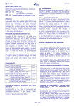
Figure 1.1: BASE + 3 Quad ADC Port modules MPA-3 system................................................... 1-1
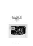
Figure 2.1: 16 port MPA-3 system ................................................................................................ 2-1
Figure 2.2: MPA-3 PCI Card ......................................................................................................... 2-2
Figure 2.3: add-on I/O port connector........................................................................................... 2-2
Figure 2.4: Extra power supply connector .................................................................................... 2-3
Figure 2.5: Rear View of the MPA-3 BASE Module...................................................................... 2-3
Figure 2.6: Quad ADC Port Module Rear View ............................................................................ 2-4
Figure 2.7: Rear cable connections of a large system.................................................................. 2-4
Figure 2.8: MPANT program startup screen ................................................................................. 2-6
Figure 2.9: 'Coincidence Definition' dialog with one SINGLE ADC .............................................. 2-6
Figure 2.10: MPANT set to one SINGLE ADC ............................................................................. 2-7
Figure 2.11: Set ADC range to 1k range....................................................................................... 2-8
Figure 2.12: START a SINGLE measurement with one ADC....................................................... 2-9
Figure 2.13: Spectrum of a basic SINGLE measurement........................................................... 2-10
Figure 2.14: Setup two ADCs for a COINCIDENCE measurement............................................ 2-11
Figure 2.15: Setup ADC range and coincidence resolving time ................................................. 2-12
Figure 2.16: Add a two-dimensional spectrum ........................................................................... 2-12
Figure 2.17: New spectrum defined ............................................................................................ 2-13
Figure 2.18: Two single and one multiparameter spectra display .............................................. 2-13
Figure 2.19: Basic RTC Experiment ........................................................................................... 2-14
Figure 2.20: System Options for RTC Experiment ..................................................................... 2-15
Figure 2.21: RealTimeClock Setup for basic Experiment ........................................................... 2-15
Figure 2.22: Auxiliary Connectors Setup for basic RTC Measurement ...................................... 2-16
Figure 2.23: RTC Spectrum Definition ........................................................................................ 2-16
Figure 2.24: Basic Time Spectra of a Single ADC...................................................................... 2-17
Figure 3.1: MPA-3 system block diagram ..................................................................................... 3-1
Figure 3.2: MPA-3 PCI Card ......................................................................................................... 3-2
Figure 3.3: PCI Card GO Line Connector ..................................................................................... 3-3
Figure 3.4: Multi I/O port connector .............................................................................................. 3-3
Figure 3.5: Digital I/O port circuit schematic ................................................................................. 3-4
Figure 3.6: BASE module front view ............................................................................................. 3-5
Figure 3.7: LED indicators in a 16 port MPA-3 system................................................................. 3-6
Figure 3.8: Auxiliary I/O circuitry ................................................................................................... 3-7
Figure 3.9: REJECT input circuit schematic ................................................................................. 3-7
Figure 3.10: Quad ADC Port module ............................................................................................ 3-8
Figure 3.11: 25 pin D-SUB ADC port connector ........................................................................... 3-9
Figure 4.1: RealTimeClock / Timer / Counter Schematic ............................................................. 4-2
Figure 4.2: Logic Schematic of Timer Control Signals.................................................................. 4-3
Figure 5.1: MPA-3 Server ............................................................................................................. 5-1
Figure 5.2: Sample MPA3.INI file.................................................................................................. 5-2
Figure 5.3: Data Operations dialog boxes for MPA data (left) and selected spectra (right) ......... 5-3
Figure 5.4: The Log Options dialog............................................................................................... 5-4
Figure 5.5: Replay Settings dialog ................................................................................................ 5-4
Figure 5.6: About MPA3 dialog box .............................................................................................. 5-5
Figure 5.7: ADC Settings and Presets dialog box ........................................................................ 5-5
Figure 5.8: Coincidence Definition dialog box .............................................................................. 5-6
Figure 5.9: Auxiliary Connectors dialog box ................................................................................. 5-7
Figure 5.10: Dig I/O and DAC Definition ....................................................................................... 5-8
Figure 5.11: Use of Real Time Clock ............................................................................................ 5-9
Figure 5.12: Remote Control dialog box ..................................................................................... 5-10
Figure 5.13: Dualparameter and Calculated spectra dialog box ................................................ 5-10
Figure 5.14: Multi Display Setting ............................................................................................... 5-11
Figure 5.15: Multi Time Display Setting ...................................................................................... 5-12
Figure 5.16: Calculated Spectrum Setting .................................................................................. 5-13
Figure 5.17: Sum of Counts Dialog............................................................................................. 5-13
ComTec GmbH
VI
Table of Figures
Figure 5.18: Sum of counts spectra before and after calibration................................................ 5-14
Figure 5.19: DLL Function Dialog ............................................................................................... 5-15
Figure 5.20: Conditions ............................................................................................................... 5-16
Figure 5.21: ROI Conditions dialog............................................................................................. 5-16
Figure 5.22: Combine Conditions dialog..................................................................................... 5-17
Figure 5.23: Opening the DDE conversation with the MPA3 server in LabVIEW ...................... 5-28
Figure 5.24: Executing a MPA3 command from a LabVIEW application ................................... 5-29
Figure 5.25: Getting the total number of data with LabVIEW ..................................................... 5-30
Figure 5.26: Getting the data with LabVIEW .............................................................................. 5-30
Figure 5.27: Closing the DDE communication in LabVIEW........................................................ 5-31
Figure 5.28: Control Panel of the demo VI for LabVIEW ............................................................ 5-31
Figure 6.1: MPANT main window ................................................................................................. 6-1
Figure 6.2: MPANT Map and Isometric display ............................................................................ 6-2
Figure 6.3: File New Display dialog box........................................................................................ 6-3
Figure 6.4: Print dialog box ........................................................................................................... 6-4
Figure 6.5: Slice and rectangular ROI Editing dialog box, left: Single spectra, right: 2D
spectra ..................................................................................................................................... 6-7
Figure 6.6: Polygonal ROI Editing dialog box ............................................................................... 6-7
Figure 6.7: Single Gaussian Peak Fit ........................................................................................... 6-8
Figure 6.8: Log file Options for the Single Gaussian Peak Fit ...................................................... 6-9
Figure 6.9: Colors dialog box ...................................................................................................... 6-10
Figure 6.10: Color Palette dialog box.......................................................................................... 6-10
Figure 6.11: Single View dialog box............................................................................................ 6-11
Figure 6.12: Custom-transformed spectra dialog ....................................................................... 6-12
Figure 6.13: MAP View dialog box.............................................................................................. 6-12
Figure 6.14: Isometric View dialog box ....................................................................................... 6-13
Figure 6.15: Axis Parameter dialog box...................................................................................... 6-14
Figure 6.16: Scale Parameters dialog box.................................................................................. 6-15
Figure 6.17: Calibration dialog box ............................................................................................. 6-16
Figure 6.18: Comments dialog box ............................................................................................. 6-17
Figure 6.19: Settings dialog box ................................................................................................. 6-17
Figure 6.20: Data Operations dialog box .................................................................................... 6-18
Figure 6.21: System Definition dialog box .................................................................................. 6-19
Figure 6.22: Spectra dialog box .................................................................................................. 6-19
Figure 6.23: Slice dialog box....................................................................................................... 6-20
Figure 6.24: Replay dialog box ................................................................................................... 6-20
Figure 6.25: Tool Bar dialog box................................................................................................. 6-21
Figure 6.26: Function keys dialog box ........................................................................................ 6-21
Figure 7.1: MPA-3 system block diagram ..................................................................................... 7-2
Figure 7.2: Power connector ......................................................................................................... 7-3
Figure 7.3: I/O port connector ....................................................................................................... 7-3
Figure 7.4: Digital I/O Port Circuitry .............................................................................................. 7-4
Figure 7.5: GO Line circuit schematic........................................................................................... 7-5
Figure 7.6: AUXi and REJECT circuit schematic.......................................................................... 7-6
Figure 7.7: ADC port connector assignment................................................................................. 7-6
Figure 7.8: ADC port circuit schematic ......................................................................................... 7-7
Figure 7.9: Add-on I/O port connector cable................................................................................. 7-8
Figure 7.10: Extra power supply connector cable......................................................................... 7-8
Figure 7.11: Standard 2m FHS link cable ..................................................................................... 7-9
Figure 7.12: FMP bus cable.......................................................................................................... 7-9
Figure 7.13: Module power supply cable ...................................................................................... 7-9
ComTec GmbH
VII
Introduction
1.
Introduction
The MPA-3 Multiparameter System is an ultra fast listmode multichannel data acquisition system
featuring data rates and performance previously not known in commercially available
multiparameter systems.
The MPA-3 system is designed to handle up to 16 external ADCs, multiscalers or time-of-flight
units. The open system technology is capable to easily accommodate future system expansions.
The modular design allows for step by step system upgrades from a minimum of 4 ADC inputs to
a maximum of 16 ports. All setup parameters are fully software controlled. Also, the MPA-3
Multiparameter System is designed to provide highest performance data acquisition it is capable
to perform simple tasks very economically while its most versatile add-on features make it easily
adaptable to a variety of experimental requirements complicated or almost impossible to fulfill
with other systems.
Figure 1.1: BASE + 3 Quad ADC Port modules MPA-3 system
For dependent multiparameter data acquisition coincidence resolving times from low 150ns to
more than 3ms can be selected in steps of 50ns. A programmable timeout counter (also 150ns to
over 3ms) for the maximum time to wait for a conversion being finished after a DEADTIME signal
of the ADC was detected further helps to optimize the data throughput for a specific experiment.
With the MPA-3 multiparameter system, FAST introduces a most flexible and versatile method to
setup coincidence mode data acquisition. Coincident events may be defined as almost any
combination of the 16 ADC ports and also the auxiliary connectors might be involved. Several
different combinations may be defined as coincidence conditions at a time. Besides, it is possible
to define the ADC ports that can actually start a coincidence independently. Thus, random
coincidences and therefore the base level noise in the spectra is further reduced.
ComTec GmbH
1-1
Introduction
With the presettable 48 bit RealTimeClock / Timer / Counter (optional) a variety of additional
information can be captured. E.g. timestamps may be inserted into the datastream to obtain
detailed information on the time particular events have occurred - with a resolution of upto 50ns.
Also scaler, multi spectra scaling, multiscaling, Time-of-Flight applications etc. may be realized
since a large variety of load, reset, capture, readout options is available.
A system wide open drain GO line that is also accessible by external devices allows for easy
synchronization with other measurement equipment.
A versatile 8 bit digital I/O1 port and an 8 bit analog output are included featuring additional
flexibility in accommodating specific experimental requirements.
Livetime correction on all ADC input ports is also provided.
The easy to use multiparameter operating software MPA-NT allows to fully control the complete
system setup. A monitoring facility provides to on-line view single and dual parameter spectra.
List data can be stored on the local harddisk drive or any other directly accessible mass storage
device. Using the PXXX harddisk array data can be stored on-line at full throughput rate for many
hours depending on the configuration.
Several single and multiparameter spectra may also be accumulated in the RAM of the PC.
Multiple windows of dual and single parameter spectra can be simultaneously displayed. Any
combination of ADCs can be selected thus, it is possible to define several single and dual
parameter spectra which can be acquired and displayed.
1 I/O: Input / Output
ComTec GmbH
1-2
Installation Procedure
2.
Installation Procedure
2.1.
Hard- and Software Requirements
The MPA-3 requires an IBM AT or compatible computer with an I486, Pentium or higher
processor and an available PCI slot. The computers power supply must be capable to provide
enough current (depending on the number of modules) from its 5V output to supply all connected
modules.
A Microsoft WINDOWS NT 4.0 or higher operating system must be installed.
2.2.
Hardware Installation
Figure 2.1: 16 port MPA-3 system
Turn off the power to your computer system and remove the line cord. Discharge your body from
any static electricity by touching a grounded surface – e.g. the metal surface of the power supply
– before performing any further hardware procedure.
FAST ComTec assumes no liability for any damage, caused directly or indirectly, by improper
installation of any components by unqualified service personnel. If you do not feel comfortable
performing the installation, consult a qualified technician.
Damage to the MPA-3 system, the computer or injury to yourself may result if power is applied
during installation.
ComTec GmbH
2-1
Installation Procedure
PCI Interface Card
Figure 2.2: MPA-3 PCI Card
Open the computer case's cover and insert the MPA-3 PCI card in an unused PCI slot. You might
first have to remove the cover from the rear of the PCI expansion slot you selected. After the card
is carefully seated in the PCI slot, make sure you fastened the card with a screw on the mounting
bracket.
Figure 2.3: add-on I/O port connector
Now install the add-on I/O port connector. In some computer cases special fittings are available
for some types of D-SUB connectors. These are particularly useful to save slots for additional
plug in cards. Otherwise mount the housing bracket with the 15 pin D-SUB connector in another
available slot of your computer. Plug in the 16 pin socket connector at the end of the ribbon cable
into the 16 pin four-walled header on the PCI card.
ComTec GmbH
2-2
Installation Procedure
Extra Power Supply Connector
Figure 2.4: Extra power supply connector
The 'Extra Power Cable' is necessary if any MPA-3 Quad ADC Port Module is connected with the
Base Module and is usually delivered with systems containing such a module. Find an available
mounting place on the rear of your PC. Mount the slot bracket with 9 pin female D-SUB connector
and plug in the floppy type power connector.
MPA-3 BASE Module
Figure 2.5: Rear View of the MPA-3 BASE Module
Find an appropriate place to set up your MPA-3 modules. This place should comply to a standard
laboratory environment. It should be dry, not exposed to direct sun shine and it should be at room
temperature.
Consider that the cable length of the ADC connections is limited to 1m. Thus, the MPA-3 modules
should be located near the ADCs.
If you not only purchased a MPA-3 BASE module but also one or more MPA-3 Quad ADC Port
modules take into account that it might be appropriate to have the BASE module as the top one in
the tower of MPA-3 modules because the auxiliary BNC connectors are better accessible and the
LED indicators are better visible. Also, the assignment of module numbers by default starts at the
BASE module and thus, the numbering of the ADC ports will be from the left top to the right
bottom (ref. Figure 1.1).
Now connect the BASE module and the PCI card using the 37 pin D-SUB connector cable (FHS
Link cable) supplied. The standard cable supplied is two meters in length but up to ten meter
ComTec GmbH
2-3
Installation Procedure
special cables are optionally available. Be sure the screws at the D-SUB connectors are
tightened.
If you have purchased the 'Extra Power Cable' also connect it to the 9 pin female D-SUB 'Extra
Power Supply' connector previously installed in the computer and to the 9 pin male D-SUB
connector named 'POWER IN' on the rear of the MPA-3 BASE module.
MPA-3 Quad ADC Port Modules
Figure 2.6: Quad ADC Port Module Rear View
We suggest you set up the tower of MPA-3 modules with the BASE module on top and the Quad
ADC Port modules below.
Figure 2.7: Rear cable connections of a large system
Now connect the power supply to the individual Quad ADC Port modules. Connect the 9 pin
female D-SUB connector 'POWER OUT' on the rear of the BASE module and the 9 pin male
D-SUB connectors 'POWER IN' on the rear of the Quad ADC Port modules using the supplied
nine core ribbon cable (ref. Figure 2.7).
ComTec GmbH
2-4
Installation Procedure
Now the FMP bus is to be connected. This is done from the right bottom to the left top. Any Quad
ADC Port module is delivered with such a short 50 core CENTRONIX cable that connects this
module to the next module towards the BASE module. Always connect the 'FMP BUS OUT' of the
lower module to the 'FMP BUS IN' of the upper one (ref. Figure 2.7). Be sure to close the side
clips of the CENTRONIX connectors.
2.3.
Software Installation
If you are using Windows 98, ME, Windows 2000 or XP, the hardware manager will recognize the
PCI card as a new hardware the first time after power on with the PCI card mounted, and will ask
for a driver. Please insert then the installation disk and specify the WDMDRIV directory on the
installation medium as the driver location.
To install the MPA-3 software on your hard disk insert the MPA-3 installation disk and start the
installation program by double clicking from the explorer
SETUP
A directory called C:\MPA3 is created on the hard disk and all MPA-3 and MPANT files are
transferred to this directory. Drive C: is taken as default drive and \MPA3 as default directory. It is
not mandatory that the MPA-3 operating software is located in this directory. You may specify
another directory during the installation or may copy the files later to any other directory.
When using Windows NT 4.0, the driver from the NTDRIVER subdirectory on the installation
medium can be installed by hand if not already done as follows, then Windows must be restarted:
A:> CD NTDRIVER <RETURN>
A:NTDRIVER> INSTALL <RETURN>
The setup wizards installs an icon for LaunchMP.EXE on the desktop. Double clicking this icon
starts the MPA-3 Hardware Server program MPA3.EXE to run in high priority. This program will
automatically call the MPANT.EXE program when it is executed. The MPA3 Server program
controls the hardware but provides no graphics display capability by itself. By using the MPANT
program, the user has complete control of the MPA-3 along with the MPANT display capabilities.
2.4.
Getting Started with a basic SINGLE measurement
What we are going to setup now is a simple SINGLE measurement using one external ADC. The
acquired spectrum will have a range of 1k channels corresponding to a 1k ADC conversion gain
setting.
First step is to start the MPA3 software by double clicking the corresponding icon. This will
automatically start the MPANT program. On startup the MPA-3 Server is iconized and one does
not have to worry about it since all hardware settings are also accessible from the MPANT
program which actually is the graphical user interface and which will appear now on your screen
(ref. Figure 2.8).
ComTec GmbH
2-5
Installation Procedure
Figure 2.8: MPANT program startup screen
Now we have to change the system settings to one ADC (default is four) only. Open the
System... menu in the Options pull-down menu (see Figure 2.8).
Figure 2.9: 'Coincidence Definition' dialog with one SINGLE ADC
Now the Coincidence Definition window should look like Figure 2.9. Close the window with OK.
The MPANT window will change to display one ADC window only (ref. Figure 2.10).
ComTec GmbH
2-6
Installation Procedure
Remove ADC1B, ADC1C and ADC1D from the Singles no coinc. by just clicking on them. If you
accidentally removed ADC1A bring it back to the Singles no coinc. field by selecting it with one
click and moving it by a click on >> below the Singles no coinc. box.
No we must set the range of the ADC to 1k. For this, open Options – Range, Preset... Change
the ADC Settings – Range to 1k = 1024 (ref. Figure 2.11) and click OK. The spectrum display of
ADC1 in the MPANT window changes to a full scale range of 1024 channels.
Figure 2.10: MPANT set to one SINGLE ADC
Be sure you connected an external pulse height analyzing ADC (set to 1k conversion gain) to the
ADC port A of module 1. Input analog signals to that ADC, e.g. from a pulser.
ComTec GmbH
2-7
Installation Procedure
Figure 2.11: Set ADC range to 1k range
Now start data acquisition by a click on the START button
(ref. Figure 2.12). Recognize that
when you move the mouse pointer over a button a help message appears in the lower left corner
of the MPANT window. In this case it is 'Erases and starts a measurement' meaning that the
contents of the histograms is erased and then a new acquisition is started. Click OK in the
message window that appears after clicking the START button.
ComTec GmbH
2-8
Installation Procedure
Figure 2.12: START a SINGLE measurement with one ADC
See that the Status changes to ON. The Real time will begin to run also indicating that data
acquisition is ON. Depending on your input signals a histogram should start to be accumulated
(ref. Figure 2.13). When you want to finish data acquisition click on the STOP button
. The
corresponding help message is 'Halts a measurement'.
ComTec GmbH
2-9
Installation Procedure
Figure 2.13: Spectrum of a basic SINGLE measurement
2.5.
Getting Started with a basic COINCIDENCE measurement
What we are going to do is to setup a basic COINCIDENCE measurement using two ADCs. The
ADCs will be set to a conversion gain of 4k. The on-line displays are set to a single spectrum for
each ADC and a two-dimensional spectrum of ADC1A x ADC1B with a resolution of 256 x 256
channels.
First open the Coincidence Definition window by a click on the System options button
. Use
the << All buttons to move all ADCs to the Not active box and then move ADC1A and ADC1B to
the Coinc. with any box with the >> button below this field. By default they are displayed with a
'S' appended indicating that they are allowed to start a coincidence resolving time window. If the
'S' is not appended check the Start enable check box for each ADC. The Coincidence Definition
window should look like Figure 2.14 now.
ComTec GmbH
2-10
Installation Procedure
Figure 2.14: Setup two ADCs for a COINCIDENCE measurement
Set the ADC ranges to 4096 using the Range, Preset… button
to get into the ADC Settings
and Preset window. Set the Coinc time to 10.00µs using the scrollbar. Then click into the data
field of DRDY Timeout and type in 50.00 to set the DRDY timeout to 50.00µs. This is in
accordance to a 100MHz Wilkinson type ADC (4k x 10ns ≈ 40µs + 10µs overhead for safety) like
our model 7074 Quad ADC. The DRDY timeout is the maximum time the system waits for
converted data (DRDY goes true) after a DEADTIME signal of the corresponding is received.
Click OK to accept the new settings and to close the ADC Settings and Preset window.
ComTec GmbH
2-11
Installation Procedure
Figure 2.15: Setup ADC range and coincidence resolving time
Now we will still have to define a two-dimensional spectrum of ADC1A x ADC1B. Open the
spectra definition window Dualparameter and Calculated spectra by a click on the Spectra button
.
In the Map and Calculated spectra window click on Add Multi… button to add a new
multiparameter spectrum. The Multi Display Setting window opens.
Figure 2.16: Add a two-dimensional spectrum
Set the x-axis of the new spectrum to ADC1A with a range of 256 and the y-axis to ADC1B with
also range 256. Type in a name for the spectrum, e.g. 'ADC 1A x 1B' like in Figure 2.16. Click
OK. In the Dualparameter and Calculated spectra window the new map appears (ref. Figure
2.17).
ComTec GmbH
2-12
Installation Procedure
Figure 2.17: New spectrum defined
Close Dualparameter and Calculated spectra and the MPANT display should show up with two
single spectra (ADC1A and ADC1B) and one multiparameter map (ref. Figure 2.18).
Figure 2.18: Two single and one multiparameter spectra display
Connect input signals to the ADCs. In case of a pulser being the signal source split the pulser
output to both ADCs since only pulses that reach ADC1A and ADC1B within a 10µs time window
(the coincidence time) are counted. Actually in this case not coincident signals are also counted
ComTec GmbH
2-13
Installation Procedure
but in the map display they will show up on the base of x- and y-axis (zero) since the respective
other ADC is read as a 'ZERO'.
Start data acquisition with the START button
End data acquisition by a click on STOP .
2.6.
. Depending on your signals spectra are shown.
Basic Usage of the RealTimeClock Option
To familiarize with the usage of the 48 bit RealTimeClock / Timer / Counter option a simple
experiment is setup. The intention is to measure the arrival time of single ADC events relatively to
a start (trigger) signal like it might be done in Time-of-Flight or similar experiments. To do so a
variable delay is used to shift analog output pulses relatively to the TTL trigger pulse that on the
other hand resets (reloads) the 48 bit counter via the AUX 1 input. Thus, in terms of TOF, the
trigger signal acts as start and the ADC deadtime signal as stop input. The delay time is then
measured with a resolution of 50ns and a time spectrum of the very ADC is accumulated.
Figure 2.19: Basic RTC Experiment
First, ADC 1A is defined as a SINGLE mode ADC (ref. Figure 2.20). Now the RTC / Timer /
Counter is set to reload (restart) with the auxiliary input AUX 1 (ref. Figure 2.21). The timer value
capture command is derived from ADC 1A DEADTIME signal (ref. OR-ed DEAD of ADC 1A in
Figure 2.21). And, last but not least, timestamps must be inserted into the datastream to transfer
the corresponding time and ADC data together. The preset value is not importent in this case but
must be at least greater than the desired time range (or zero which will automatically change to
the maximum value). For the count source 20MHz is selected to use the internal 50ns crystal
clock.
Take care that the AUX 1 interface is used as input (ouput disabled – ref. Figure 2.22). Since the
here used analog pulser triggers on the falling edge the AUX 1 input polarity is 'active high' to
reload the timer when the TTL signal is high and let the timer free run when it is low.
To visualize the timing relationship a spectrum is defined that shows the arrival time on the x-axis,
the adc pulse height on the y-axis and the countrate in z-direction (ref. Figure 2.23). Also a one
dimensional spectrum is defined (set ADC range to 1) to show just a time spectrum (projection
onto the x-axis).
In Figure 2.24 the resulting spectra can be seen. Watching the map display (window (1))
amplitude variations show up as vertical lines whereas delay time variations result in horizontal
lines. Window (4) is the corresponding three-dimensional view, window (3) the pulse height
analysis and (5) the time spectrum.
ComTec GmbH
2-14
Installation Procedure
Figure 2.20: System Options for RTC Experiment
Figure 2.21: RealTimeClock Setup for basic Experiment
ComTec GmbH
2-15
Installation Procedure
Figure 2.22: Auxiliary Connectors Setup for basic RTC Measurement
Figure 2.23: RTC Spectrum Definition
ComTec GmbH
2-16
Installation Procedure
Figure 2.24: Basic Time Spectra of a Single ADC
ComTec GmbH
2-17
Hardware Description
3.
Hardware Description
3.1.
Overview
The modular concept of the MPA-3 system is designed to enable easy accommodation to a huge
variety of experimental requirements.
GO LINE
AUX 1
AUX 2
REJECT
Digital I/O
Analog Out
8
BASE MODULE
ADC A
ADC B
ADC C
ADC D
ADC 2A
ADC 2B
ADC 2C
ADC 2D
QUAD ADC PORT MODULE
ADC A
QUAD ADC
ADC B
INTERFACE
ADC C
ADC D
ADC 3A
ADC 3B
ADC 3C
ADC 3D
QUAD ADC PORT MODULE
ADC A
QUAD ADC
ADC B
INTERFACE
ADC C
ADC D
ADC 4A
ADC 4B
ADC 4C
ADC 4D
QUAD ADC PORT MODULE
ADC A
QUAD ADC
ADC B
INTERFACE
ADC C
ADC D
ADD-ON PORTS
COINCIDENCE
TIMER
FMP BUS
INTERFACE
ADC 1A
ADC 1B
ADC 1C
ADC 1D
PCI INTERFACE CARD
FHS LINK
INTERFACE
CONTROL
EVENT
DETECT/REJECT
PCI Interface
FIFO
1024 x 32
48 BIT RTC /
TIMER / COUNTER
FMP BUS
FMP BUS
FMP BUS
QUAD ADC
INTERFACE
Control
FHS LINK
Figure 3.1: MPA-3 system block diagram
It is step by step expandable by up to three Quad ADC Port modules2 to a maximum of sixteen
ADC inputs. It also features a versatile user programmable 8 bit digital input and output port.
Furthermore a programmable analog output is provided that allows to e.g. remote control a high
voltage supply etc. Moreover, three BNC connectors at the BASE module provide additional
programmable I/O features.
And, last but not least, a system wide open drain 'GO' line enables any connected device to start
and stop all participating measurement equipment simultaneously. This allows for easy
synchronization of electronic devices previously often not possible.
2 Number and types of modules applicable may increase in the future
ComTec GmbH
3-1
Hardware Description
3.2.
PCI Card
R I/O
Analog Output
Range Potentiometer
Analog Output
Range Selector
Digital I/O Port
onboard Header
R Pull
GO- Line Connector
3V-7V 5V
3 2 1 WP.
FHS- Link Connector
Write Protect Selector
Fuse
Figure 3.2: MPA-3 PCI Card
3.2.1.
General
The MPA-3 PCI Card is the interface between the MPA-3 BASE module and the PCI Bus of the
computer. It is a short 5V PCI bus master card compliant to the PCI specification 2.1. The bus
master capability offers a theoretical PCI burst transfer rate of 132 Mbyte/s. Also there is a
1024x32 bit FIFO3 on board which buffers the measurement data and thus minimizes the system
deadtime considerably.
3 FIFO: First In, First Out
ComTec GmbH
3-2
Hardware Description
3.2.2.
'GO' Line Connector
Figure 3.3: PCI Card GO Line Connector
In order to synchronize other computer cards to a measurement - e.g. a scaler card - there is a
two pin 'GO' line connector on board. The 'GO' line is a system wide open drain wired-AND signal
which can start and stop a measurement. This line is also available on the Multi I/O port
connector (ref. Figure 3.4). For details on the circuitry of the 'GO' line ref. Figure 7.5. This line
may be set and reset by the software.
3.2.3.
Digital I/O Port
A very versatile 8 bit digital I/O port is implemented on the 16 pin four-walled header. The
supplied ribbon cable connects to a 15 pin female D-SUB connector fixed on a mounting bracket.
Since the resistors are socket mounted (ref. Figure 3.2: MPA-3 PCI Card) they can be easily user
configured in a most flexible way. This I/O port is fully software controllable and each single (1 bit)
port is individually configurable. It might be used for external alert signals, sample changer
control, status inputs / outputs etc.
fixed
GO
DIGIO 0
DIGIO 2
DIGIO 4
DIGIO 6
GND
8 Bit DAC
VCC
- 1
- 3
- 5
- 7
- 9
- 11
- 13
- 15
2
4
6
8
10
12
14
16
-
GND
DIGIO 1
DIGIO 3
DIGIO 5
DIGIO 7
AGND
AGND
AGND
onboard header
GO
DIGIO 0
DIGIO 2
DIGIO 4
DIGIO 6
GND
8 Bit DAC
VCC
-
1
2
3
4
5
6
7
8
9
10
11
12
13
14
15
-
GND
DIGIO 1
DIGIO 3
DIGIO 5
DIGIO 7
AGND
AGND
Legend:
DIGIO 0...7 = Digital I/O Port Bit 0...7
GO
= Go-Line
8 Bit DAC = 8 bit analog output (0..5V or 6,5V)
GND
AGND
= Digital ground
= Analog ground
female D-SUB connector
Figure 3.4: Multi I/O port connector
As can be seen from Figure 3.5 each bit of the digital I/O port might be configured as input only
(tri-stated output), pull-up, pull-down (large R PULL) or driver output (small R PULL) with
readback capability. Wired-OR / AND connections are also possible.
ComTec GmbH
3-3
Hardware Description
DENi
DOUTi
R Pull
R I/O
DINi
Digital I/Oi
Legend:
DEN
DOUT
DIN
R Pull
R I/O
= Data output driver enabl e
= Data output driver
= Data input
= 4.7 kOhms (default)
= 100 Ohms (default)
Figure 3.5: Digital I/O port circuit schematic
3.2.4.
Analog Output
A 8 bit Digital-to-Analog converter provides a software programmable analog output voltage. The
full scale output voltage range is jumper selectable between fixed +5V and screw driver
adjustable +3,5V to +7V. (Ref. Figure 3.2: MPA-3 PCI Card)
3.2.5.
Power Supply
The MPA-3 PCI Card itself is powered by the 5V connectors of the PCI Slot. The MPA-3 BASE
and MPA-3 Quad ADC Port modules again are powered by the MPA-3 PCI Card through the FHS
Link. To prevent the PCI Card and the PC from damage, e.g. in case of an external shortcut,
there is a 4A mini fuse onboard (Ref. Figure 3.2: MPA-3 PCI Card).
3.2.6.
FHS Link
Ref. chapter 3.3.4
3.2.7.
Nonvolatile Memory
For saving card specific information there is a 256x8 bit serial EEPROM onboard. It might be
used in the future for information regarding driver upgrades, changes of PCI bus specification etc.
To prevent it from unintentional erasing or overwriting it is write protected by jumper setting. (Ref.
Figure 3.2: MPA-3 PCI Card)
ComTec GmbH
3-4
Hardware Description
3.3.
BASE Module
3.3.1.
General
Figure 3.6: BASE module front view
The MPA-3 BASE module is the heart of the MPA-3 multiparameter system. It provides the
interface to the PC as well as the interface to the subsequent modules which, so far may be up to
three Quad ADC Port4 modules. Besides, the BASE module already includes four ADC ports for
the connection of external ADCs, Multiscalers, Position Analyzers, Time-of-Flight units etc. The
BASE module also distributes the power to the subsequent modules.
In COINCIDENCE mode of operation it detects and evaluates coincident arriving ADC events.
3.3.2.
Signature PLD
On the BASE module's printed circuit board a 20 pin DIL socket holding a programmable logic
device (PLD) that contains specific information on the individual MPA-3 system. Particularly it
holds an encrypted unique serial number of the very system. This information can be obtained
from the MPA-3 Server program and is used for support purposes (ref. Figure 5.6 on page 5-5).
3.3.3.
Power Supply
The MPA-3 system is powered by the 5V PC power supply. The power connection is basicly done
by the FHS Link cable. For higher power consumptions an 'Extra Power Cable' is optionally
available.
For system configurations where the voltage drop across the FHS Link cable is low – e.g. since
only one module is connected, the FHS Link is a short cable etc. - the FHS Link cable provides all
the supply current required. When more power is needed than the FHS Link cable is able to
provide an extra power input connector (POWER IN) for the optional 'Extra Power Cable' is
provided on the rear of the BASE module. A frontside LED marked "POWER " indicates whether
the power supply is sufficient or not. When the 'POWER' LED is not illuminated the 'Extra Power
Cable' must be installed.
4 Number and types of modules applicable may increase in the future
ComTec GmbH
3-5
Hardware Description
When the PC is turned off the power supply connection between the BASE module and the PC is
opened by a relay inside the BASE module to prevent backloading of the PC power supply by
externally connected electronics.
3.3.4.
FHS Link
The FAST High Speed (FHS) Link connects the MPA-3 frontend BASE module to the computer. It
provides full duplex high speed data transfer at up to 420 Mbit/s.
3.3.5.
FMP Bus
The FMP (FAST MultiParameter) bus connects the subsequent modules and the BASE module.
All status and setup information from and to the subsequent modules respectively the individual
ADC ports is transferred over the FMP bus. More important, also the ADC data is transmitted
over the FMP bus to the BASE module for further transfer to the PC in listmode.
This bus furthermore transmits the DEADTIME signals of up to sixteen ADC input ports to the
BASE module for coincidence detection in COINCIDENCE mode and for ADC livetime
information that is transferred to the PC with a resolution of 1ms.
The systemwide 'GO' line is also available on the FMP bus.
3.3.6.
Indicators
For a quick observation of the system status some LED indicators are provided on the BASE
module's frontside.
First the 'POWER' LED shows - if green– that the power supply is sufficient for proper operation.
If it is off - even when the connection to the PC is made and the PC is turned on - the 'Extra
Power Cable' must be installed.
Figure 3.7: LED indicators in a 16 port MPA-3 system
The 'ACTIVE' LED is illuminated green when the system is armed i.e. the MPA-3 is ready to
receive and transmit ADC data.
ComTec GmbH
3-6
Hardware Description
The 'BUSY' is on (red) when either data is being transferred to the PC or when a coincidence
event is processed. Thus, it gives a quick indication of the system load.
Finally, a seven segment display shows the module number assigned to the Quad ADC Port type
module already included in the BASE module. After power up it will show an '8'. After software
start the connected modules are initialized and module numbers are assigned to each individual
module. These module numbers are displayed on the seven segment display and help to identify
the individual ADC ports. Example: when an '1' is assigned the ADC ports of the very module will
mean 'ADC 1A', 'ADC 1B', 'ADC 1C' and 'ADC 1D' (from left to right).
3.3.7.
Auxiliary I/O Connectors
Two BNC type connectors AUX 1 & 2 located on the front of the BASE module.
VCC
VCC
4k7
100R
AUXi
AUXi I/O
Figure 3.8: Auxiliary I/O circuitry
The auxiliary connectors provide two additional bidirectional ports. These can be used for a
variety of software configurable features (ref Figure 5.9: Auxiliary Connectors dialog box).
3.3.8.
REJECT Input
The REJECT input also is a BNC type connector located on the frontside of the MPA-3 BASE
module. It provides additional flexibility in COINCIDENCE mode of operation (ref. Figure 5.9:
Auxiliary Connectors dialog box on page 5-7).
VCC
VCC
4k7
REJECT
1k0
REJECT IN
22p
Figure 3.9: REJECT input circuit schematic
ComTec GmbH
3-7
Hardware Description
3.3.9.
48 bit RealTimeClock / Timer / Counter
The 48 bit RealTimeClock (RTC) / Timer / Counter is built from a 48 bit synchronuous downcounter. To enable reliable capture and read operation a pipeline of two registers (ref. Figure 4.1)
is provided. As can be seen the actual counter contents is read into a capture register on the
registrate (capture) counter command. Then it is shifted into the transfer register. During a timer
data transfer into the computer being in progress the transfer register is disabled (locked) to
prevent changing the data while a read cycle is still active. This is necessary since the 48 bit data
is in fact read in three subsequent 16 bit operations.
Whenever 'TIMER_LOAD' is asserted also a 'REGISTRATE COUNTER' command is executed
which overwrites possible old data and ensures that on a subsequent transfer operation only data
from the actual timer cycles is used.
On reaching 0 (zero) 'PRESET REACHED' goes TRUE and, if a preset is enabled, the counter is
stopped. Also, if selected, the GO-line is reset.
Refer chapter 4.5 for a detailed description of the timer functions.
3.3.10. ADC Ports
These are four standard nuclear ADC interface ports with DataReady / DataAccepted handshake.
For a detailed description refer chapter 3.4.2.
3.4.
Quad ADC Port Module
3.4.1.
General
The MPA-3 Quad ADC Port module provides an interface for to up to four nuclear ADCs,
Multiscalers, Position Analyzers, Time-of-Flight units etc.
Up to three such modules might be installed in a MPA-3 system.
Figure 3.10: Quad ADC Port module
During initialization a module number is assigned to each MPA-3 Quad ADC Port module. This
module number is shown on a seven segment display on the frontside of the module. Thus, the
individual ADC ports can be easily identified.
3.4.2.
ADC Ports
The MPA-3 ADC ports support up to 16 bit (64k channel) ADCs, TOFs etc. Since all control signal
polarities are software selectable almost any known nuclear ADC, TOF etc. might be connected.
ComTec GmbH
3-8
Hardware Description
D0 - 1
D1 - 2
D2 - 3
D3 - 4
D4 - 5
D5 - 6
D6 - 7
D7 - 8
D8 - 9
D9 - 10
D10 - 11
D11 - 12
D12 - 13
14 - DRDY
15 - D13
16 - D14
17 - DACC
18 - ENC
19 - D15
20 - GND
21 - DEAD TIME
22 - DENB
23 - GND
24 - GND
25 - GND
Legend:
D0...D15 = Data Bit 0...15 (input)
DRDY = Data Ready (input)
DACC = Data Accepted (output)
ENC = Enable Converter (output)
DEAD TIME = ADC Dead Time Signal (input)
DENB = Data Enable (output)
GND = Ground
Figure 3.11: 25 pin D-SUB ADC port connector
D0...15 - Active low data input signals
DRDY - Data Ready input signal indicating that valid data is present at the ADC port. The polarity
is software selectable.
DACC - Data Accepted output signal. Indicates that the input data is registered. The polarity is
software selectable.
DEAD TIME - Dead Time input signal. The polarity is software selectable.
ENC - Enable Converter output signal to arm the connected ADC, TOF, etc. The polarity is
software selectable.
DENB - Output signal to enable a tri-state data output driver of the ADC, TOF, etc. The polarity is
software selectable.
The handshake is quite easy: when the ADC asserts a DRDY the port registers the valid ADC
data and then signals a DACC. After that the ADC removes DRDY and the module then
deasserts DACC.
In COINCIDENCE mode of operation after the data being registered ENC (enable converter) is
deasserted to prevent the ADC from further conversions before the coincidence resolving time
and the processing of the actual coincidence event has ended.
In COINCIDENCE mode it is required that DEADTIME preceeds DRDY by at least 200ns (ref.
also chapter 4.3).
ComTec GmbH
3-9
Functional Description
4.
Functional Description
4.1.
General
Basicly there exist two modes of operation: SINGLE and COINCIDENCE and of course any
mixture of both. The mode of operation of each port is individually selectable.
Generally all transfer of ADC data to the PC is done blockwise and in listmode, i.e. one after the
other with some overhead. The overhead consists of words for synchronization purposes and
some header information. The synchronization words provide a means to reconstruct data
structure if a transmission error accidentally occured. The header words contain the information
which data will follow in the data block. Deadtime or actually Livetime data of the ADCs is also
transfered in listmode.
The BASE module fetches the ADC data from the ADC input ports and transmits it in listmode to
the FIFO buffer on the PCI card. In COINCIDENCE mode it first checks if the coincidence
conditions are met. Every millisecond LIVETIME information of the ADC ports is inserted into the
list data stream.
4.2.
SINGLE Mode
In SINGLE mode of operation the ADCs operate independently of each other. When a valid
converted event of an ADC is received from an ADC it is directly transfered to the PC. When
several ADCs send data simultaneously all the data can be transmitted to the PC in one block
thus saving system deadtime.
When the ADC asserts DRDY the data is registered in the input register of the corresponding port
and DACC is answered to the ADC. Then the ADC will remove DRDY and DACC is also
deasserted. After registering the data a BUSY is signaled to the BASE module to indicate that
new data is present and can be transfered to the PC.
When an ADC port detects a DRDY signal it checks if previous (not yet transmitted) data is still
present in its input register. If the port is still busy with old data it asserts DACC but does not
register the new data. Thus - in case of old data still being left to transfer - it discards the new
ADC data and makes sure the old data is not overwritten before it is transfered.
4.3.
COINCIDENCE Mode
The basic purpose of introducing COINCIDENCE mode is to accumulate only data that meets
some predefined timing relationship. Events that will be accumulated must fall within the
coincidence resolving time window. Thus, events that do not fall within this time window will be
discarded and do not show up in the histogrammed spectra.
The versatility of the coincidence definitions in the MPA-3 system allows to select various
combinations of ADC events that either have to occur within the coincidence time window or
where just some have to occur to accumulate them.
In COINCIDENCE mode of operation the active going edge (programmable rising or falling edge)
of the ADC's DEADTIME signal is used as time-of-arrival of an ADC event. This is done because
the DEADTIME signal usually is the most accurate time information obtainable from an ADC.
On detecting an active going edge of a DEADTIME signal a coincidence resolving time window is
opened. While a coincidence window is open all arriving DEADTIME edges are stored. After the
coincidence time has elapsed the system waits for all BUSY (DRDY) signals of the corresponding
ADC ports (meaning that the port contains valid data) to become true. The maximum time to wait
for this is software selectable (ref. DRDY timeout - Figure 5.7: ADC Settings and Presets dialog
box on page 5-5). When all expected BUSYs have arrived - or at the latest when the DRDY
ComTec GmbH
4-1
Functional Description
timeout elapsed – the corresponding ports are read and the data is transfered to the PC in
listmode. If a port has no new data (BUSY is still false when timeout occurs) a zero is transfered
for this port.
The ADC ports that are allowed to open a coincidence time window are software selectable (ref.
Figure 5.8: Coincidence Definition dialog box on page 5-6). This enables for further data
reduction.
In COINCIDENCE mode of operation the corresponding ADC ports accept new data only when a
coincidence time window is open. This is usefull to reduce the system deadtime caused by not
coincident or unwanted ADC events. This is why in this mode the DEADTIME signals must
precede the corresponding DRDYs by at least 200ns.
4.4.
DEADTIME Detection
The DEADTIME signals coming from the ADCs are synchronized to the internal 10MHz clock
provided at each ADC port. Then they are transfered to the BASE module where in conjunction
with an edge detection the coincidence resolving is processed. Furthermore every one
millisecond all the inverted DEADTIME signals (i.e. the LIVETIME signals) are sampled and the
result is transmitted to the PCI card. Thus, every millisecond an image of the DEADTIME state of
all connected ADCs is inserted into the listmode data stream. On the one hand this provides time
stamps every 1ms in the data stream and on the other hand also a statistical means for
LIVETIME correction with a resolution of one millisecond.
4.5.
48 bit RealTimeClock / Timer / Counter
The 48 bit RealTimeClock (RTC) / Timer / Counter is built from a 48 bit synchronuous downcounter. Any time 'TIMER_LOAD' (ref. Figure 4.1) is TRUE the counter is loaded with the stored
preset value. When 'TIMER_LOAD' is FALSE and 'TIMER_ENABLE' is TRUE the counter is
decremented with a 50ns cycle time whenever 'TIMER_COUNT' is TRUE. While 'TIMER_LOAD'
and 'TIMER_ENABLE' are level sensitiv signals 'TIMER_COUNT' goes TRUE for 50ns on every
detected edge of the appropriate source signals (ref. chapter 5.1.5).
Figure 4.1: RealTimeClock / Timer / Counter Schematic
As can be seen the actual counter contents is read into the capture register on the registrate
(capture) counter command. Then it is shifted into the transfer register. During a timer data
transfer into the computer being in progress the transfer register is disabled (locked) to prevent
changing the data while a read cycle is still active. This is necessary since the 48 bit data is in
fact read in three subsequent 16 bit operations.
ComTec GmbH
4-2
Functional Description
The control signals to the timer are derived from a logic OR of the enabled input signals.
Particularly 'TIMER_COUNT' may be derived from a large variety of signals (ref. chapter 5.1.5 for
more details) incl. all DEADTIME signals and the AUX connectors.
'TIMER_COUNT' is selectable from:
•
20MHz clock (real time with 50ns resolution)
•
pos./neg. edge of AUX 1
•
pos./neg. edge of AUX 2
•
pos./neg. edge of REJECT
'TIMER_LOAD' is selectable from:
•
Software only
•
low/high of AUX 1
•
low/high of AUX 2
•
low/high of REJECT
•
Wrap around (reloads the preset value when zero is reached)
'TIMER_ENABLE' is selectable from a logic AND of 'SYSTEM ON' and AUX 1, AUX 2 or REJECT
respectively.
Figure 4.2: Logic Schematic of Timer Control Signals
'REGISTRATE COUNTER' is selectable from:
•
logic OR-ed edges of any selected DEADTIME signals. Also edges of AUX 1, AUX 2 or
REJECT may be included
•
internal coincidence start signal
•
internal coincidence end (finished) signal
Whenever a 'TIMER_LOAD' is asserted also a 'REGISTRATE COUNTER' command is executed.
On reaching 0 (zero) 'PRESET REACHED' goes TRUE and if a preset is enabled the counter is
stopped.
ComTec GmbH
4-3
Windows Server Program
5.
Windows Server Program
The window of the MPA-3 server program MPA3.EXE is shown here. It enables the full control of
the MPA-3 to perform measurements and save data. This program has no own graphic
capabilities, but it provides - via a DLL ("dynamic link library“) - access to all functions,
parameters and data. The server can be completely controlled from the MPANT software that
provides all necessary graphic displays.
Figure 5.1: MPA-3 Server
5.1.
Server functions
To start the software, just double click a shortcut icon linking to the server program. The server
program performs a test whether DMA mode works well on this computer, then starts MPANT
and gets iconized. Usually you will control everything from MPANT, but it is possible to work with
the server alone and independently from MPANT.
NOTE:
To go sure that no events are lost due to a full FIFO when working with MPANT and other
applications, we strongly recommend that the MPA-3 server program runs in high priority. This
can be achieved either by starting the software via LaunchMP.EXE or by using the Windows task
manager (use the “Processes” tab and right click the entry for MPA3.EXE).
5.1.1.
Initialisation files
At program start the configuration files MPA3.INI (contains - for example - the ADC port
handshake signal polarities; see Figure 5.2) and MPA3.CNF are loaded. Instead of this
MPA3.CNF file any other setup file can be used if its name - excluding the appendix ‘.CNF’ - is
passed as a command line parameter (e.g. MPA3 TEST to load TEST.CNF) .
In the MPA3.INI file the hardware configuration and some settings are defined, that can be
changed only by editing this file explicitly using a text editor. The number of ADC interfaces must
be specified. If the number of interfaces defined is different from the number of interfaces found,
the software terminates immediately and opens the notepad editor with the MPA3.INI loaded.
Change then the line adcnum= , enter the correct number and save the file. If you have the
REPLAY option set replver=1 if it is enabled in the MPA- base module, or replver=2 if you have a
hardlock that allows REPLAY on a remote computer not connected with MPA-3 hardware. If you
have the Timestamp Real time clock option, set rtc=1.
ComTec GmbH
5-1
Windows Server Program
Two parameters allow to define the DMA transfer settings. 'timeout' defines the time after a DMA
transfer is terminated if it is not finished, and 'blocksize' defines the number of double words of
data to be transmitted in a single DMA transfer. The default value of 1024 is for moderate
counting rates. For very high counting rates you may chose a value like 4096 or 16384. One
special thread in the software handles only the DMA transfer. It starts immediately after a transfer
is completed a new one acting on a second buffer and signals to a second thread that a buffer is
ready for evaluation. These two threads run in parallel to the message handling and display
refresh routines. Windows NT is able to perform the threads automatically in parallel on two
processors on a dual processor system. Another parameters that can be set only by editing the
MPA3.INI file is the updaterate in msec for the refresh of the status. Very important is also the
correct setting of the ADC handshake polarities. If you have for example Silena ADCs, remove
the semicolon at the first position of the line after “; Silena or Lane ADC’s” and insert a semicolon
in the line after “; FAST or Canberra ADC’s”.
Figure 5.2: Sample MPA3.INI file
5.1.2.
Action menu
The server program normally is shown as an icon in the taskbar. After clicking the icon it is
opened to show the status window. Using the „Start“ menu item from the action menu a
measurement can be started. In the status window every second the acquired events, the
counting rate and the time are shown. Clicking the „Halt“ menu item the measurement is stopped
and via „Continue“ proceeded.
ComTec GmbH
5-2
Windows Server Program
5.1.3.
File menu
Clicking in the File menu on the Data... item opens the Data Operations dialog box.
Figure 5.3: Data Operations dialog boxes for MPA data (left) and selected spectra (right)
This dialog allows to edit the data format settings and perform operations like Save, Load, Add,
Subtract, Smooth and Erase. The Radio Buttons MPA, Selected Spectra and New Spectra
provide a choice between handling of the compete data set (MPA) or selected spectra, or to load
new selected spectra for compare. Mark the checkbox Save at Halt to write a MPA file containing
the configuration and all spectra at the stop of a measurement. The filename can be entered. If
the checkbox auto incr. is crossed, a 3-digit number is appended to the filename that is
automatically incremented with each saving. The format of the data can be ASCII (extension for
seperated spectra .ASC), binary (.DAT), GANAAS (.SPE), CSV (.CSV). If Seperate Header is
not checked, the Header and data is saved together in a file with extension .MP, otherwise the file
with extension .MP contains only the header and the data is written seperately into a file with
appropriate extension. The buttons Save, Load, and Erase perform the respective operation.
With Add and Sub spectra can be added or subtracted from the present data. The checkbox
calibr. can be checked to use a calibration and to shift the data then according to the calibration.
The Smooth button performs an n-point smoothing of selected single spectra. The number of
points to average can be set with the Pts edit field between 2 and 21. Check the Write Listfile
checkbox to write a listfile during a run. No Histogramming prevents calculating any spectra to
save computing time and concentrate the system on writing the listfile. It is possible to reduce the
size of list files by writing reduced timer data. When "Write Listfile" is enabled in the data
operations dialog, a checkbox Reduce timer data will be visible and you have a choice between
a factor of 10, 100 or 1000 corresponding to timer events every 10, 100 or 1000 msec instead of
every 1 msec. Of course the resolution of the real- and live time will be reduced by this factor
when evaluating the listfile. A checkbox named Drop 'zero events' allows to drop coincidence
events with all ADC data being zero. Such events may arise strongly if the input signals to the
ADCs have some noise as such a noise signal can make a deadtime signal which starts a
coincidence window also if the signal is too low for a valid conversion. Such events will then also
be eliminated before writing them into a listfile.
A log file can be written. The log file options can be edited in a dialog that can be entered from
the data options dialog pressing the Log... button.. See for the set of control commands that
support opening, closing and writing text into log files in the on-line help or in chapter 5.2.
ComTec GmbH
5-3
Windows Server Program
Figure 5.4: The Log Options dialog
If Replay is enabled in the MPA3 Base module or the Replay Keymodule is connected to LPT1,
the menu item File – Replay... opens the Replay dialog (see above for the correct entry in the
mpa3.ini file).
Figure 5.5: Replay Settings dialog
Enable Replay Mode using the checkbox and specify a Filename of a list file (extension .LST)
or search one by pressing Browse... With the radio buttons it is possible either to choose the
complete listfile by selecting All or a selected Time Range. Specify the real time range in
seconds by editing the respective edit fields from: and Preset: . The Replay Speed can be
specified in units of 100 kB per sec. To Use Modified Settings enable the corresponding
checkbox, otherwise the original settings are used. To start Replay press then Start in the Action
menu or the corresponding MPANT toolbar icon. The Replay dialog has an additional Checkbox
"Write ASCII (.als)". It allows to convert the binary listfile into an ASCII file. It has the usual header
and then the listfile data in the following ASCII format (1 line per event tag):
C 0 268
; Coincidence ADC data in ADC 0 at channel 268 (decimal)
S 1 534
; Single ADC data in ADC 1 at channel 534 (decimal)
T fff8
; Timer (msec) event, ADC0..2 are "dead", the others "alive"
; (hex fff8)
ES a
; Single event flag, data in ADC1 and ADC3 (hex a)
ComTec GmbH
5-4
Windows Server Program
EC 5
; Coincidence event flag, data in ADC0 and ADC2 (hex 5)
RTC 576
0
0
; RTC data rtc0, rtc1, rtc2 (decimal)
The menu item File – About... opens the About MPA3 window where some information of the very
MPA-3 System can be found. Particularly the serial number (ref. Figure 5.6 above the mouse
pointer) is important for support purposes. This serial number is unique for each MPA-3 system.
Figure 5.6: About MPA3 dialog box
The MCDWIN menu item in the file menu starts the MCDWIN program if it is not running.
5.1.4.
Settings dialog
Clicking in the Settings menu on ADC... item opens the ADC Settings and Presets dialog box.
Here parameters like presets, range parameters, coincidence time, etc. can be set.
Figure 5.7: ADC Settings and Presets dialog box
In the edit field Range the length of the spectrum can be chosen between 2 and 65536. Set All
sets the range for all ADCs, otherwise each ADC can be selected from the drop down list and
changed seperately. If the checkbox ROIpreset is marked, the measurement will be stopped after
acquiring more events than specified in the corresponding edit field. The events are counted only
ComTec GmbH
5-5
Windows Server Program
if they are within the ROI5 limits, i.e. >= the lower limit and < the upper limit. Another possibility is
to acquire data for a given run time via the RTimepreset or a given live time via the
LTimepreset. A measurement will be stopped if the corresponding checkbox is marked. The
width of the coincidence window can be set between 0.15 and 3276 µsec in steps of 50 nsec by
entering the number or using the scroll bar. The Data Ready Timeout can be set within the same
limits. It must be large enough to cover the ADC conversion time. OK takes all settings. Cancel
cancels all changes. Pressing Save Settings writes all settings into the file MPA3.CNF resp. the
entered setup name.
Figure 5.8: Coincidence Definition dialog box
5.1.5.
Coincidence Definition dialog
Clicking in the Settings menu on System... opens the Coincidence Definition dialog box. Here the
several ADCs can be combined to be used either in single mode, i.e. without regarding any
coincidence, to be not activated, or to use it in coincidence mode. The Button <<All removes all
ADCs from the respective list above it. To insert an ADC into a list, first select it in the list where it
is and then press the >> button below the list where you want to insert it. To change an ADC
from single mode into coincidence mode, first deactivate it and then insert it into the list Coinc.
with any. Any ADC inserted into that list by default has the ability to start a coincidence time
window. If you want to disable it, uncheck the checkbox Start enable. An 'S' after an ADC name
in the list indicates whether the Start of coincidence window is enabled or not. You can then
define Dependent coincidence groups by inserting selected ADCs from the 'Coinc. with any' list
into one of the four available groups. ADCs in one of the groups must all have data within the
same coincidence window, otherwise the event is dropped. The same ADC may be in several
groups, therefore it is possible either to move >> or copy >> it into a Dependent coincidence
group.
Click OK to accept all settings. Cancel cancels all changes. Clicking „Save Settings“ stores all
settings in the file MPA3.CNF.
5 ROI: Region Of Interest
ComTec GmbH
5-6
Windows Server Program
Figure 5.9: Auxiliary Connectors dialog box
The Aux conn... button opens the Auxiliary Connectors dialog to define the use of the auxiliary
connectors. The AUX1 and AUX2 connectors both can be used either as an input or an output. In
input mode Coincidence Mode must be checked to get it into the 'coinc. with any' list. Start
Coincidence can be checked to allow starting a coincidence resolving time window from the
input connector. The Polarity of the TTL signal can be set by checking or unchecking Pol. active
low. For use as an output, check Enable Output and choose any of the signals from the drop
down list.
Available output signals are:
coinc_start
indicates the start (opening) of a coincidence resolving time window
coinc_run
active while a coincidence resolving time window is open
coinc_active
active while a coincidence event is processed
(coincidence resolving time + processing time)
dead_store
requests the sampling of the DEADTIME (LIVETIME) state of the ADC
ports – active every one millisecond when MPA-3 is enabled (enca is
true)
enca
enable converter all – internal enable MPA-3 system signal
'1'
outputs a HIGH
'0'
outputs a LOW
GO
mirrors the GO line (note: open drain output)
For systems with the Timestamp Real time clock option (RTC), the AUX2 connector has in
addition the following two output signals:
preset_reached
indicates the Preset reached condition (only when 'Halt when preset
reached' is enabled in the RTC dialog)
timer_load
indicates that the timer was reset to the start value.
Particularly the GO signal may be useful to monitor directly whether an acquisition is running or
not. The REJECT Input connector can be used similar to the AUX inputs. Check Coincidence
Mode to have /REJ in the 'Coinc. with any' list. A signal to the Reject input then drops any
coincidence event in the corresponding coincidence group, either Instantly or At End of
Coincidence window.
ComTec GmbH
5-7
Windows Server Program
Note: only one of the three auxiliary connectors should be used in coincidence mode. In principle
it sometimes might be useful to use AUX1 and AUX2 together. In this case the signals are
internally "OR"ed.
The use of the digital input / output ports can be defined by opening the Dig IO and DAC
definition dialog by pressing the respective button Dig, DAC... from the systems dialog.
Figure 5.10: Dig I/O and DAC Definition
The digital input / output port can be used either to show the status in bit 0 (bit 0 set means
acquisition ON) if the checkbox Status Dig 0 is checked, or it can be used for example for a
sample changer by checking Value inc. at Stop . Here, the 8 bit value entered in the edit field ( a
number between 0 and 255) is output at the Dig I/O port. This value will always be incremented
by one if a run is stopped.
Together with using bit 0 as status signal, it is also possible to use the digital input #6 as an
external trigger for starting the system (DESY control line). If the corresponding checkbox is
marked, a start command will not immediately start the system. After the start command, the data
is cleared if the corresponding checkbox Clear is marked and digital input will be continuously
checked for its logical level. If the level changes from high to low, the acquisition is started. It will
stop if the level returns to high (or vice versa if Invert is marked), and with the next level change
again cleared and restarted and so on. A stop command for the system will finish the digital input
checking.
NOTE: It is recommended to disable DMA mode by setting nodma=1 in the MPA3.INI file and
running the MPA3.EXE in normal priority (start directly, not using the LAUNCHMP.EXE program)
when using this Dig 6 input polling.
The use of the optional Timestamp Real time clock RTC can be set by opening the Use of Real
Time Clock dialog by pressing the respective button RTC... from the Coincidence Definitions
dialog.
ComTec GmbH
5-8
Windows Server Program
Figure 5.11: Use of Real Time Clock
The RTC can insert 48 bit timer data into the listdata stream. Check Timestamp in datastream
to enable it. The timer starts from a defined preset value that can be defined in the Preset edit
field together with the Unit selection listbox and counts down. It is possible to stop the
measurement after the preset time by enabling Halt when preset reached. The time unit for the
preset can be nsec, µsec, msec, sec and h. The timer runs usually with 20 MHz, but the Count
Source can be selected between the internal 20 MHz timer or an external counter or clock taken
from the edge of a signal input at the AUX1, AUX2 or REJ connectors. The Timer runs when the
acquisition is ON or gated by 'AUX2 and ON', 'AUX1 and ON' or 'REJ and ON' as selected from
the respective selection box. Preset load Mode defines the start time. It can be 'Software only'
i.e. start together with the acquisition, or an extern signal from AUX2, AUX1, REJ, or 'wrap
around' i.e. the counter starts immediately again with the preset value after zero was reached.
Please check the polarity of the AUX input signal in the Auxiliary connectors dialog, if you use any
of the auxiliary connectors for timer load or -capture. The Time Capture defines when the RTC
value is inserted into the datastream. It can be selected between OR'ed DEAD (DOR), DOR or
AUX2, DOR or AUX1, DOR or REJ, Coinc Start, Coinc End, Coinc OK (it is equivalent to Coinc
End) and 'Software only' (presently not used). The ORed DEAD of ADC is explicitly defined by a
checkbox for each available ADC input. So for each ADC individually can be set that its DEAD
time signal may capture a timer value into the data stream.
The „Remote mode...“ item in the settings menu or the „Remote“ button in the System Definition
dialog box opens the Remote Control dialog box. Here all settings can be made for the control of
the MPA-3 server program via a serial port.
ComTec GmbH
5-9
Windows Server Program
Figure 5.12: Remote Control dialog box
If the Checkbox „Use Remote Control“ is marked and the necessary DLL is available (Order the
MPA-3 EXTERNAL CONTROL software option), the specified COM port will be used for
accepting commands. If „Echo command“ is marked, the input line will be echoed after the
newline character was sent. „Echo character“, on the other hand, immediately echoes each
character. The possible commands and their syntax are listed in the following section.
5.1.6.
Dualparameter and Calculated spectra dialog
By clicking Spectra... in the Settings menu the Dualparameter and Calculated Spectra dialog box
of the MPA3 server is called. Here additional multi parameter and calculated spectra can be
added, modified and deleted from the list.
Figure 5.13: Dualparameter and Calculated spectra dialog box
Press Add Multi to define a new multi parameter spectra in the Multi Display Settings dialog.
ComTec GmbH
5-10
Windows Server Program
Figure 5.14: Multi Display Setting
For the x Axis and y Axis a parameter and range must be chosen from the respective drop down
list. A Name can be entered for the new multi spectra, or you can left the 'Name' edit field
untouched to choose an automatically generated name like 1A x 1B. If Conditions are defined,
one can be selected as a necessary Condition for incrementing a channel in this dualparameter
spectra. For zoomed Maps check the x Offset and y Offset checkbox and enter a value for the
respective Offsets and Compression. The Offset point marks the lower left corner of the zoomed
map, and the Compr. by 2^n means the power of two by which the spectra are compressed. A
value of zero means full resolution.
Press Add Time to define a new Time spectra in the Multi Time Display Settings dialog.
ComTec GmbH
5-11
Windows Server Program
Figure 5.15: Multi Time Display Setting
For the x Axis and y Axis a parameter and range must be chosen from the respective drop down
list. The time axis can be either the x Axis or the y Axis, select the respective radio button. The
time parameter can be either the 1 msec Real time from the standard real / live timer or the 50
nsec RTC clock when the respective option is available and 'Timestamp in data stream' was
checked in the RTC dialog. Define the Time Offset and Time Bin size in the corresponding edit
fields and Unit selection boxes. A Name can be entered for the new time spectra, or you can left
the 'Name' edit field untouched to choose an automatically generated name like RTC x 1A. If
Conditions are defined, one can be selected as a necessary Condition for incrementing a
channel in this spectra. For zoomed Maps check the x Offset or y Offset checkbox and enter a
value for the respective Offsets and Compression. The Offset point marks the lower left corner of
the zoomed map, and the Compr. by 2^n means the power of two by which the spectra are
compressed. A value of zero means full resolution. For a one-dimensional time spectrum just use
1 for the ADC range.
Press Add Calc from the Map and Calculated Spectra dialog to define a new calculated single
spectrum in the Calculated Spectrum Setting dialog.
ComTec GmbH
5-12
Windows Server Program
Figure 5.16: Calculated Spectrum Setting
You have a choice between several formulas to combine two ADC parameters: Pos = Range *
right / (left + right) is a formula often used with position sensitive detectors read out from both
sides. Sum = left + right makes a sum spectrum, and Div = Range * left / right can be used to
divide two spectra. The Range and Name can be defined in the edit fields or default values will
be taken. Any such calculated spectrum can be used as a parameter for a multi parameter
spectrum. If Conditions are defined, one can be selected as a necessary Condition for
incrementing a channel in this spectra. The COPY type of spectra allows to set conditions for
copies of primary ADC spectra. HISTORY allows to display a history plot of an ADC as a new
spectra, i.e. you can see the data of the ADC as they come in versus the event number. The
length of the history plot can be defined free, just edit the Range number.
MPA-3 Server version 1.87 (Jul-21-2010): It is now possible to create spectra containing the sum
of counts from several ADC's. It can be used to create a "superdetector" from multiple smaller
detectors. It doesn't matter if the ADC's are used in single or coincidence mode, the sum spectra
is calculated from the complete single spectra. Choose Spectra... from the MPANT options menu
or the corresponding toolbar icon, click "Add Calc..." and select the "Or = Sum of counts" radio
button.
Figure 5.17: Sum of Counts Dialog
ComTec GmbH
5-13
Windows Server Program
In the "Sum of counts" dialog you can select which ADCs will contribute to the superdetector. It is
recommended to enable "Use Calibration" and to perform a careful calibration of all selected
ADC's:
Make a short acquisition using a pulser or a calibration source so you get a peak in each used
ADC. In each ADC zoom into the spectra, then by keeping the right mouse button pressed drag
from left to right over the peak to mark a fit region and click on the "Fit" toolbar icon to make a
Gaussian peak fit. Note the position value of the peak in the first ADC. For the first ADC you can
just enable "Use Calibration" in the calibration dialog and use the standard parameters p0=0,
p1=1. In the next ADC enter two calibration points: for the first point enter 0 for the Channel and 0
for the value and click "Add>>". For the second calibration point use the result of the fit: Click "Fit"
to enter the Channel value of the fitted peak position. For the "Value" enter the fit result of the
peak position in the first ADC. Click "Calibrate" and enable "Use Calibration", then click "OK".
Proceed this way until all used ADCs are calibrated. You will immediately get the effect: Instead
of a peak multiplet you will see a single sharp peak in the sum spectra.
Figure 5.18: Sum of counts spectra before and after calibration
The automatic generated spectra name is for example "OR_3_C". The 3 is here an hexadecimal
bit pattern indicating that ADC1 (bit 0) and ADC2 (bit 1) contribute to the OR sum. The C at the
end of the name means that "Use Calibration" is enabled.
ComTec GmbH
5-14
Windows Server Program
By selecting "DLL function" and pressing the Edit... button a dialog "Dll Function" is opened.
Figure 5.19: DLL Function Dialog
The calculated spectrum is a function programmed in the DMPA3.DLL, for example RTab(Xpar,
Ypar, Zpar). Xpar is the "left" parameter, Ypar the "right" parameter. Run the TSTRXY.EXE
program to create a sample table file and try the dlltest.cnf configuration: For a 2D position
dependent energy spectra correction now as a sample a function named
unsigned long RTab(long x, long y, long z)
is implemented in the DLL. It is calculated by looking up in a table as z * Tab[x,y] and must be
initialised by using the DLL function named
int IniTab(LPSTR filename);
The Cleanup function CloseTab() frees the memory allocated by IniTab. A sample table can be
calculated by using a program tstrxy.exe. It assumes a Gaussion function for the position
dependent energy calibration of a 2D position dependent detector. The names of these DLL
functions and the filename containing the table must be provided in the DLL Function dialog, and
also the dimensions XRange and YRange of the table. The Xpar and Ypar parameters are shifted
to fit their spectra range into the table dimensions. In the optional available DLL software interface
for LabVIEW and Visual Basic the complete sources of the DMPA3.DLL and TSTRXY.EXE are
included to allow own written applications for calculated spectra based on this example (the
customer dependent functions of the DLL are in a small module "custom.c").
Another example of a DLL function that is already implemented is for using any ADC input as a
sweepcounter parameter. The Initialise function is "IniSweep", the Table filename can be
"Dummy", the Cleanup DLL function is "CloseTab", and the DLL function is "IncSweep". Select
the ADC used as a counter for all three parameters. Please refer to the documentation of the
optional DLL software interface for more information.
Press Conditions... from the Map and Calculated Spectra dialog to define or edit ROI Conditions
in the Conditions dialog.
ComTec GmbH
5-15
Windows Server Program
Figure 5.20: Conditions
To define a new condition, press Add... to open the ROI Condition dialog.
Figure 5.21: ROI Conditions dialog
Here it is possible to define a Condition as an event inside or outside of an ROI in any spectra.
There are two drop-down list boxes for the Parameter and ROI. Of course the ROI must be
defined before by using the MPANT program, it is not possible here to add any new ROI. A
checkbox labeled NOT in ROI allows to define a condition as an event outside the ROI. Using the
edit field Name it is possible to define a name for the Condition. A default name built by the
parameter name and ROI number will be set automatically. Now also a name for the ROI can be
entered and edited here (ver. 1.71, Feb 2007). This helps to fix the condition to a unique ROI.
Press Combine... to open the Combine Conditions dialog.
ComTec GmbH
5-16
Windows Server Program
Figure 5.22: Combine Conditions dialog
Here it is possible to define a Condition as a combination using the Boolean operators NOT, OR
or AND of already defined conditions. The OR will be symbolized in the automatically generated
name by a plus sign "+", the AND by an asterisk "*".
ComTec GmbH
5-17
Windows Server Program
5.2.
Control Language
A sequence of commands that are stored in a file with extension .CTL can be executed by the
MPA-3 server program or MPANT with the „Load “ command. Also the configuration files
MPA3.CNF or the header files with extension .MP contain such commands to set the parameters.
Each command starts at the beginning of a new line with a typical keyword, the case is ignored.
Any other characters in a line may contain a value or a comment.
Following methods are available to execute commands:
• Load the command file using the Load command in the file menu.
• Enable remote mode in the server and send commands via the serial connection. A special
DLL is necessary which is part of the optional available MPA-3 EXTERNAL CONTROL
software.
• Open a DDE connection and send the commands via DDE as described in section 5.4. The
application name for opening the DDE connection with the standard MPA-3 server program
MPA3.EXE is MPA3, the topic is MPA3-. Implemented are the DDE Execute to perform any
command, and the DDE Request with items RANGE and DATA.
• Send the commands over a TCP/IP net using a remote shell and the optional available MPA-3
EXTERNAL CONTROL software. It is necessary to have a TCP/IP Winsock installed like the
Trumpet winsockets and that the remote shell daemon program MPWNET is running. See the
readme file on the installation disk.
• Send the commands via the DLL interface from LabVIEW, a Visual Basic program or any
other application (software including the complete source code of the DLL and examples
optional available).
• From your own Windows application, register a Windows message and then send the
command as can be seen in the DLL source code.
ComTec GmbH
5-18
Windows Server Program
The file MPA3.CNF contains a complete list of commands for setting parameters; an example is:
wndwidth=237
; Sets width of server window
wndheight=263
; Sets height of server window
loglevel=7
; controls the logging of actions into the log file (hex format):
; bit 0 = 1 START, bit 1 = 1 STOP, bit 2 = 1 SAVE are
; protocoled with time into the logfile. (Default: loglevel=7)
loguse=0
; use of log file:
; bit 0 = 1 ON, bit 1 = 1 ON at program start, bit 2 = 1 append
logfile=filename
; log file name
ctm=80
; Coincidence time in units of 50 nsec.
; A value of 80 means 5 mikrosec
dtm=4000
; Data Ready timeout in units of 50 nsec.
sen=0
; Start coincidence window enable word (hex).
; Bit 0 means Start enable for ADC1A, Bit 1 for ADC1B...
coi=0
; Coincidence enable word (hex)
; Bit 0 means Coinc. enable for ADC1A ...
aui=a003
; AUX IN control word (hex)
; defines the use of AUX connectors for input:
; bit 0: AUX 2 polarity, 1 = active low
; bit 1: AUX 1 polarity, 1 = active low
; bit 2: AUX 2 start enable
; bit 3: AUX 1 start enable
; bit 4: AUX 2 coinc mode
; bit 5: AUX 1 coinc mode
; bit 12: /REJECT coinc mode
; bit 13: REJECT polarity, 1 = active low
; bit 15: Reject mode: 0 = instantly, 1 = at end of coinc. time
auo=0
; AUX OUT control word (hex)
; defines the use of AUX connectors for output:
; bit 0..3 AUX 2 output multiplexer: 0 = coinc_start, 1 = coinc_run,
;
2 = coinc_active, 3 = coinc_ok, 4 = dead_store,
;
5 = enca, 6 = 1, 7 = 0
; bit 4..7 AUX 1 output multiplexer
; bit 8 AUX 2 output enable
; bit 9 AUX 1 output enable
; bit 10 AUX 2 mirror GO line (AUXMUX=7)
; bit 11 AUX 1 mirror GO line (AUXMUX=7)
dac=0
; DAC value 0..255
diguse=0
; Use of Digital I/O (hex):
; bit 0: DIG I/O bit 7 output status
; bit 1: Invert Polarity
; bit 2: Input bit 6 Trigger System
; bit 3: Clear before start triggered with DIG I/O bit 6
; bit 6: Output digval and increment digval after stop
; bit 7: Input Mode: =0 Resistive, =1 Tristate
; bit 8: Input Mode: =0 Pull-up, =1 Pull-down
digval=0
; DIG I/O Output value
rtprena=0
; Run time Preset enable
rtpreset=1000.000
; Run time Preset value (seconds)
ComTec GmbH
5-19
Windows Server Program
autoinc=0
; 1=Enable Auto increment of filename
savedata=0
; 1=Save at Halt
mpafmt=dat
; data format used in MPA files
; (dat=binary, asc=ASCII, spe=GANAAS)
sephead=0
; 1=Seperated Header file (extension MP) and
; Data file (extension dat, asc or spe) for seperated spectra
fmt=dat
; data format used in seperated spectra (extension MP)
; (dat=binary, asc=ASCII, spe=GANAAS)
smoothpts=5
; Number of points to average for a smooth operation
[ADC1]
; The following section concerns parameters of ADC1 (= ADC1A)
range=8192
; Spectrum length
active=1
; Definition word for ADCs and spectra :
; active & 0xFF ==0 not used
; ==1 single
; ==2 coinc with any
;
bit 4..7 in group 1..4
; Definition words for calculated spectra:
; active & 0xF ==3 MAP, ((x-xoffs)>>xsh) x ((y-yoffs)>>ysh)
; ==0xB TIM, MAP with RTC or RT as x or y
; ((x-xoffs)>>xsh) x ((y-timeoffs)>>timesh)
; or((x-timeoffs)>>timesh x ((y-yoffs)>>ysh)
; bit4==1: x zoomed MAP
; bit5==1; y zoomed MAP
; ==4 POS, (y<<xsh) /(x + y)
; ==5 SUM, (x + y)
; ==6 DIV, (x<<xsh) / y
;
bit 4..7 in group 1..4
;
bit 8..11 xsh, bit 12..15 ysh or bit 8..15 xsh
prena=0
; bit0=1: Livetime preset enabled
; bit1=1: ROI preset enabled
ltpreset=1000.000
; Livetime preset value
roipreset=10000
; ROI preset value
roimin=0
; Lower ROI limit
roimax=8192
; Higher ROI limit
caluse=0
; bit 0=1: Use calibration, higher bits: calibration formula
calch0=0.00
; First calibration point channel
calvl0=0.000000
; First calibration point value
calch1=100.00
; Second calibration point channel
calvl1=100.000000
; Second calibration point value
caloff=0.000000
; Calibration parameter: Offset
calfact=1.000000
; Calibration parameter: Factor
calunit=keV
; Calibration unit
[ADC2];
; The following section concerns parameters of ADC2 (= ADC1B)
...
ComTec GmbH
5-20
Windows Server Program
[MAP0] 1A x 1B
; The following section concerns parameters of a MAP spectra
; named 1A x 1B, the number 0 is an index starting at 0 for the
; first calculated spectra
param=10000
; Paramer definition (hex): the lower word defines the x-axis
; parameter (here 0 == ADC1A), the higher word the y axis (here
; 1 == ADC1B)
...
[TIM1] RTC x 1A
; The following section concerns parameters of a Time spectrum
; named RTC x 1A
param=101
; Paramer definition (hex): the lower word defines the x-axis
; parameter (here 101 == RTC), the higher word the y axis (here
; 0 == ADC1A) The 1 msec Real Time (RT) has parameter value
; 100 (hex), the RTC 101 (hex)
The following commands define Replay settings and are not included in a MPA3.CNF file:
repluse=1
; Set REPLAY mode ON (or OFF for repluse=0)
replmodif=1
; Set Modified Settings for REPLAY to ON
; (or OFF for replmodif=0)
repllimit=1
; Set REPLAY limited time Range to ON
; (repllimit=0 means complete listfile)
repltimefrom=0
; Set Start time for Replay in listfile to 0 seconds
repltimepreset=60
; Set Replay time preset in listfile to 60 seconds
replname=file
; Set list filename for REPLAY
replspeed=x
; Set Replay speed to x
...
A data header file with extension .MP contains a subset of above parameters and some
additional information typical for the special measurement. An example is:
ctm=80
dtm=80
sen=3
coi=3
aui=0
auo=0
auxsys=0
dac=0
diguse=0
digval=0
rtprena=0
rtpreset=1000.000
autoinc=0
savedata=0
ComTec GmbH
5-21
Windows Server Program
mpafmt=dat
sephead=1
fmt=dat
smoothpts=5
[ADC0]
REPORT-FILE from 11/03/86 08:00:00 written 09/02/98 16:51:04
; the first time is when the measurement was started,
nd
; the 2 when the data file was written
realtime=0.00
; real time in seconds
livetime=0.00
; live time in seconds
TOTALSUM=3067757 ; total sum of counts
ROISUM=3062969
; sum of counts in ROI
ROINET=3034311
; sum in ROI with background subtracted
cmline0=11/03/86 08:00:00
; comment lines: the first line always contains the start time
cmline1=ADC1
; the second line contains the title of the spectrum
range=4096
; subset of parameters as in a MPA3.CNF file...
active=2
prena=0
ltpreset=1000.000
roipreset=10000
roimin=2
roimax=4096
caloff=0.000000
calfact=1.000000
calfact2=0
calfact3=0
calunit=keV
caluse=0
roi=182 192 ;Peak 1
; after the semicolon is the optional ROI name
roi=257 268
roi=289 298
roi=352 364
roi=551 559
roi=601 615
roi=849 864
roi=1121 1134
roi=1443 1463
roi=1777 1801
ComTec GmbH
5-22
Windows Server Program
roi=1961 1988
roi=2909 2925
roi=2924 2943
roi=4036 4055
roi=2573 2590
The following commands perform actions and therefore usually are not included in a MPA3.CNF
file:
start
; Clears the data and starts a new acquisition. Further
; execution of the .CTL file is suspended until any
; acquisition stops due to a preset.
halt
; Stops acquisition if one is running.
cont
; Continues acquisition. If a time preset
; is already reached, the time preset
; is prolongated by the value which
; was valid when the „start„ command
; was executed. Further execution of
; the .CTL file is suspended (see start).
savecnf
; Writes the settings into MPA3.CNF
savempa
; Saves all configuration and spectra data.
; An existing file is overwritten.
pushname
; pushes the actual mpa filename on an internal stack that can hold 4
; names.
popname
; pops the last mpa filename from the internal stack.
loadmpa
; Loads mpa data; the filename
; must be specified before with a command mpaname=...
addmpa
; Adds mpa data to actual spectra; the filename
; must be specified before with a command mpaname=...
submpa
; Subtracts mpa data from actual spectra; the filename
; must be specified before with a command mpaname=...
erasempa
; Clears all spectra.
MPA
; Sets actual device to MPA for the following
; commands of the controlfile. (equivalent to ADC=0)
ADC=1
; Sets actual ADC to ADC1 (=ADC1A, 2=ADC1B,..) for the
; following commands of the controlfile.
savedat
; Saves data of actual ADC as seperated
; spectrum (extension .MP) An existing file
; is overwritten.
loaddat
; Loads data of actual ADC, the filename
; must be specified before with a command datname=...
adddat
; Adds data into actual ADC spectra; the filename
; must be specified before with a command datname=...
subdat
; Subtracts data from actual ADC spectra; the filename
; must be specified before with a command datname=...
smooth
; Smoothes the data in actual ADC spectra
ComTec GmbH
5-23
Windows Server Program
erasedat
; Clears the data of actual ADC spectra.
exit
; Exits the server (and MPANT) programs
alert Message
; Displays a Messagebox containing Message and an OK
; button that must be pressed before execution can continue.
waitinfo 5000 Message ; Displays a Messagebox containing Message, an OK
; and an END button. After the specified time (5000 msec)
; the Messagebox vanishes and execution continues. OK
; continues immediately, END escapes execution.
beep *
; Makes a beep. The character '*' may be replaced with '?', '!' or
; left empty. The corresponding sound is defined in the WIN.INI
; file in the [sounds] section.
delay 4000
; Waits specified time (4000 msec = 4 sec).
pulse 100
; Outputs a pulse of 100 ms duration at dig 3.
waitpin 4000
; Waits 4000 ms for going the level at dig 5 going low.
; After a timeout a Messagebox warns and waits for pressing OK
; Can be used for connecting a sample changer.
run controlfile
; Runs a sequence of commands stored in controlfile. This
; command cannot be nested, i.e. it is not possible to execute
; a run command from the controlfile called with a run command,
; only if it was called with a load command.
onstart command
; The command is executed always after a start action when the
; acquisition is already running. The command can be any valid
; command, also 'run controlfile' is possible.
onstart off
; Switches off the 'onstart' feature. Also a manual Stop command
; switches it off.
onstop command
; The command is executed always after a stop caused by a
; preset reached or trigger. This can be used to program measure
; cycles. For example the command 'onstop start' makes a
; loop of this kind.
onstop off
; Switches off the 'onstop' feature. Also a manual Stop command
; switches it off.
lastrun=5
; Defines the file count for the last run in a measure cycle. After a
; file with this count or greater was saved with autoinc on, instead
; of the 'onstop command' the 'onlast command' is executed.
numruns=5
; Defines the file count for the last run in a measure cycle. The
; last count is the present one plus the numruns number.After a
; file with this count was saved with autoinc on, instead of the
; 'onstop command' the 'onlast command' is executed.
onlast command
; The command is executed after a stop caused by a preset
; reached or trigger instead of the 'onstop command', when the
; last file count is reached with autoinc on. This can be used to
; finish programmed measure cycles.
onlast off
; Switches off the 'onlast' feature. Also a manual Stop command
; switches it off.
exec program
; Executes a Windows program or .PIF file.
; Example: exec notepad test.ctl
; opens the notepad editor and loads test.ctl.
updatestatus
; Send a message to the MPANT program to update the status
ComTec GmbH
5-24
Windows Server Program
fitrois
; Makes a single peak Gaussian fit for all ROIs in the active
; Display of MPANT and dumps the result into a logfile. This is
; performed by the MPANT program and therefore can be
; made only if this application is running.
fitrois SP_1
; Similar to the fitroi command, but using the argument allows to
; specify which spectrum should be evaluated independently of
; which child window is activated in MPANT. SP_1 means ADC1
; (=ADC1A)
autocal
; Makes a single peak Gaussian fit for all ROIs in the active
; Display of MPANT for which a peak value was entered in the
; MPANT Region Edit dialog and uses the results for a
; calibration. This is performed by the MPANT program and
; therefore can be made only if this application is running.
autocal SP_1
; Similar to the autocal command, but using the argument allows
; to specify which spectrum should be evaluated independently of
; which child window is activated in MPANT
closedsp SP_5
; Close all views of specified spectra in the MPANT program.
; The view can be reopened in MPANT with "Open All" from the
; File menu. May be used to free computer resources by closing
; displays of large MAP spectra.
openall
; opens all spectra in MPANT
openlog logfilename
; Opens a logfile for writing while erasing an existing file
; of the same name.
openlogprompt
; Opens a new logfile with the name entered in the logprompt
; dialog
appendlog logfilename ; Opens a logfile for writing in append mode to an
; eventually already existing file of the same name
closelog
; Closes the logfile. When the server exits, the logfile is
; also closed.
showlog
; Opens the notepad editor showing the logfile.
logtime
; Writes the date and time in a format mon/day/year hh:mm:ss
; into the logfile
logsums
; Writes the non zero totalsums of all spectra into the logfile
logwrite text
; Writes a line of text into the logfile
logprompt title
; Opens a dialogbox to enter any text with title and writes
; title and text into the logfile
if(even)command
if(odd)command
; executes a command if the current run number is even or odd,
; respectively.
delnamedroi roiname
; deletes named ROI
selnamedroi roiname
; selects named ROI in MPANT spectra displays
deleteallrois
; deletes all ROIs in the active MPANT window.
deleteallrois SP_#
; allows to delete all ROIs of a specified spectra (1 for # means ADC1A..).
ComTec GmbH
5-25
Windows Server Program
The following commands make sense only when using the serial line or TCP/IP control interface:
MPA?
; Sends the MPA status via the serial port or LAN and make
; MPA actual.
ADC1?
; Sends the status of ADC1 and make ADC1 actual.
...
ADC16?
; Sends the status of ADC16 and make it actual.
?
; Send the status of the actual ADC
RROI(0,1)
; Sends the sum, mean value and max positive and negative
; deviation from mean of rectangular ROI #1 in spectra #0
PROI(400)
; Sends the sum, mean value and max positive and negative
; deviation from mean value of polygonal ROI with id #400
sendfile filename
; Sends the ASCII file with name ‘filename’ via the serial line.
The execution of a control file can be finished from the Server or MPANT with any Halt command.
5.3.
List file format
The list file starts with an ASCII header containing the settings as described above. The header
ends with a line containing [LISTDATA]. Then the list data follow in binary format. The structure is
as follows:
Every millisecond there is a timer event. It is a 32 bit word containing 0x4000 as high word and as
low word for ADC 1 a 1 in bit 0 if it's "alive" and a 0 if its "dead", the same for ADC2 in bit 1 and
so on. Counting the corresponding set bits directly gives the live time in milliseconds for each
ADC, counting the timer words gives the real time of the run in milliseconds. It is possible that the
timer is written only every 10, 100 or 1000 milliseconds. This is then indicated by a line
"timerreduce=10" (100, 1000, respectively) immediately preceding the [LISTDATA] tag in the
header of the listfile.
After a timer event can follow either again a timer event or a synchronize mark, i.e. a double word
containing 0xFFFFFFFF and then event data.
Event data start always with a event signal double word containing in the high word some flags
and a zero in bit 30 (to distinguish it from a timer event), and in the low word for each ADC that
has data a 1 in the corresponding bit (bit 0 for ADC1 ...). The ADC data are 16 bit and the data
structure is in a 32 bit raster, therefore there must be a 16 bit dummy word inserted for an odd
number of ADCs containing data to get an even number of 16 bit data words. If such a dummy
was inserted, this is marked in bit 31 of the event signal word. If data of the 48 bit real time clock
(RTC) are in the event, this is marked in bit 28 of the event signal word.
If RTC data are signaled in the event signal double word, the three 16 bit RTC data rtc0, rtc1 and
rtc2 follow immediately after the signal word in the next low, high and low words. The rtc value is
(rtc2 * 65536 + rtc1) * 65536 + rtc0. It starts from a (preset) value that can be set by software and
counts down with 20 MHz (or extern clock). After rtc2 follows in a high word the dummy word if bit
31 in the event signal double word was set, or ADC data.
If RTC data were not signaled, immediately after the signal double word follows in the next low
word either a dummy word (if signaled in bit 31) or ADC data (starting from the lowest ADC that
has data). From the signal double word it is clear how many ADC data follow and also that it is an
even number of 16 bit words, so after this set of data can either again follow a new set starting
with a new event signal double word, or a new live time event.
ComTec GmbH
5-26
Windows Server Program
5.4.
DATA file format
The .mpa format is used to save all spectra in a single file. It starts with an ASCII header
containing the settings and then the spectra follow one after the other, each preceded with a
header line like
[DATA0,4096]
(This means the first single spectra with a length of 4096 channels.)
[DATA1,4096]
(This means the second single spectra...)
[CDAT0,16384]
(This is the first dual parameter or calculated spectra with a length of 16384 channels. The
enumeration starts again at zero after all "physical" spectra.)
The format of the data itself can be ASCII, binary, GANAAS or CSV (see below). For dual
parameter spectra look in the header for the parameters range and xdim. range is the total
number of channels, xdim the length of the x parameter. param describes which parameters are
used for the x- and y-axes. For an 256x256 map of ADC1 (=x-parameter) and ADC2 (=yparameter) the data in the file is such that 256 ADC1 values are at ADC2=0 and then 256 ADC1
values at ADC2=1 etc.
Individual spectra can also be saved into single files. Such spectra data is written into two
separate files, one with extension .mp containing configuration data and one containing pure
spectra data with an extension indicating the chosen format. The .mp file contains the settings in
ASCII format using the control language described in section 5.2.
Spectra data files with extension .asc contain in each line one decimal number in ASCII
containing the corresponding count value in the histogram.
Binary data files with extension .dat are written with 4 bytes per data value, as usual in the Intel
world in reverse order i.e. the least significant byte comes first.
GANAAS files can be read with the respective gamma spectra evaluation software by the IAEA
and have the extension .spe. It is an ASCII format with a small header containing after a tag
$SPEC_ID: a title, after a tag $MEAS.TIM: a line containing two numbers for the live time and
real time, then a tag $DATE_MEA: and the date and time of the measurement start, then a tag
$MCA_CAL: and two lines containing the order of the polynomial function for the energy
calibration and the polynome coefficients. After a tag $DATA: follow the spectra data in ASCII
with 10 values per line.
A special ASCII format for 2D files with extension .csv can be read with the MPAWIN software for
the older FAST ComTec MPA/PC multi parameter system (if the extension is changed into .asc).
It has got a small header starting with a line [DISPLAY] and ending with a line [DATA] and then
only for each non zero data point a line containing 3 values separated by TAB characters, the x
and y channel numbers and the channel content.
ComTec GmbH
5-27
Windows Server Program
5.5.
Controlling the MPA-3 Windows Server via DDE
The MPA3 program can be a server for a DDE (Dynamic Data Exchange). Many Windows
software packages can use the DDE standard protocols to communicate with other Windows
programs, for example GRAMS, FAMOS or LabVIEW. In the following the DDE capabilities of the
MPA3 program are described together with a demo VI („Virtual Instrument“) for LabVIEW. It is not
recommended to use the DDE protocol for LabVIEW, as a DLL interface is (optionally) available
which works much faster. The following should be seen as a general description of the DDE
conversation capabilities of the MPA3 program.
5.5.1.
Open Conversation
application: MPA3
topic: MPA3Any application that wants to be a client of a DDE server, must first open the conversation by
specifying an application and a topic name. The application name is MPA3 and the topic is
MPA3-.
Figure 5.23: Opening the DDE conversation with the MPA3 server in LabVIEW
5.5.2.
DDE Execute
The DDE Execute command can be used to perform any action of the MPA3 program. Any of the
Control command lines described in chapter 5.2 can be used. For example a sequence of control
commands saved in a file TEST.CTL can be executed by specifying the command:
RUN TEST.CTL
The MPA3 program then executes the command and, after finishing, it sends an Acknowledge
message to the DDE client. This can be used for synchronizing the actions in both applications.
ComTec GmbH
5-28
Windows Server Program
Figure 5.24: Executing a MPA3 command from a LabVIEW application
5.5.3.
DDE Request
The DDE Request is a message exchange to obtain the value of a specified item. Only two items
are defined for DDE request up to now: RANGE and DATA. The value is obtained as an ASCII
string, i.e. it must be converted by the client to get the numbers. All other parameters concerning
the MPA3 Setup can be obtained by the client application by reading and evaluating the
configuration file.
RANGE
The RANGE item can be used to obtain the total number of data in the actual ADC spectra. The
desired ADC analyzer can be selected before by a command ADC=1, ..., ADC=16.
ComTec GmbH
5-29
Windows Server Program
Figure 5.25: Getting the total number of data with LabVIEW
DATA
With the DATA item the data are obtained. The value of this item is a multiline string that contains
in each line a decimal number as an ASCII string.
Figure 5.26: Getting the data with LabVIEW
5.5.4.
Close Conversation
After finishing the DDE communication with the MPA3 program, it must be closed.
ComTec GmbH
5-30
Windows Server Program
Figure 5.27: Closing the DDE communication in LabVIEW
The following figure shows the „Panel“ of the described VI for LabVIEW.
Figure 5.28: Control Panel of the demo VI for LabVIEW
ComTec GmbH
5-31
Windows Server Program
5.6.
Controlling the MPA-3 Windows Server via DLL
The MPA3 server program provides - via a DLL („dynamic link library“) - access to all functions,
parameters and data. So the server can be completely controlled from the MPANT software that
provides all necessary graphic displays.
In the following some parts of the header files of the DMPA3.DLL are listed, that may help an
experienced programmer to use the DLL for own written applications. Please note that the
complete documented source code of the DLL including fundamental VIs and an example VI for
LabVIEW and example program in Visual Basic is available as an option.
#define
#define
#define
#define
#define
#define
ST_LIVETIME
ST_DEADTIME
ST_TOTALSUM
ST_ROISUM
ST_TOTALRATE
ST_NETSUM
0
1
2
3
4
5
typedef struct{
double cnt[6];
//
//
//
//
unsigned long val;
} ACQSTATUS;
#define
#define
#define
#define
#define
#define
ST_REALTIME
ST_RUNTIME
ST_SINGLESUM
ST_COINCSUM
ST_SGLRATE
ST_COIRATE
//
//
//
//
0
1
2
3
4
5
MPA status: real time in sec,
elapsed computer-runtime, total single events
total coinc events, rate of single events, rate of coinc events
aquisition status: 0= HALT, 1= ON
typedef struct {
long savedata;
long autoinc;
long fmt;
long sepfmt;
long sephead;
long smpts;
long caluse;
char filename[256];
char specfile[256];
char command[256];
} DATSETTING;
typedef struct{
long range;
long prena;
long
long
long
long
ADC status: Livetime in msec,
Deadtime in percent,
total sum, roi sum, total rate, net sum
Maximum value in spectrum
roimin;
roimax;
nregions;
caluse;
long calpoints;
long param;
long offset;
long xdim;
ComTec GmbH
//
//
//
//
//
//
//
//
//
//
//
//
//
//
//
//
//
//
//
1 if auto save after stop
1 if auto increment filename
format type: 0 == ASCII, 1 == binary,
2 == GANAAS
format for seperate spectra:
seperate Header
spectrum length
bit 0: lifetime preset enabled
bit 1: ROI preset enabled
lower ROI limit
upper limit: roimin <= channel < roimax
number of regions
bit0: 1 if calibration used,
higher bits: formula
number of calibration points
for MAP and POS: LOWORD=x, HIGHWORD=y
zoomed MAPS: LOWORD: xoffset,
HIGHWORD, yoffset
x resolution of maps
5-32
Windows Server Program
long active;
double roipreset;
double ltpreset;
} ACQSETTING;
//
//
//
//
//
//
//
//
//
//
//
typedef struct{
unsigned long HUGE *s0;
unsigned long *region;
unsigned char *comment0;
double *cnt;
HANDLE hs0;
HANDLE hrg;
HANDLE hcm;
HANDLE hct;
} ACQDATA;
typedef struct {
int sen;
int coi;
int ctm;
int dtm;
int tct;
int tp0;
int tp1;
int tp2;
int aui;
int auo;
int bk0;
int bk1;
int dac;
int diguse;
int digval ;
int rtprena;
double rtpreset;
} ACQMP3;
typedef struct {
int nDevices;
int nDisplays;
int nSystems;
int bRemote;
int auxsys;
int sys0[16];
int sys1[16];
} ACQDEF;
ComTec GmbH
//
//
//
//
//
//
//
//
//
//
//
//
//
//
//
//
//
//
//
//
//
//
//
Spectrum definition word:
active & 0xFF ==0 not used
==1 single
==2 coinc with any
==3 MAP,
((x-xoffs)>>xsh) x ((y-yoffs)>>ysh)
==4 POS, (y<<xsh) /(x + y)
bit 4..7 in group 1..4
bit 8..11 xsh, bit 12..15 ysh
ROI preset value
livetime preset value
//
//
//
//
pointer
pointer
pointer
pointer
to
to
to
to
spectrum
regions
strings
counters
Start Enable Register
Coincidence Control Register
Coinc. Time in units of 50 ns
Data Ready Timeout
Time Stamp Control Register
Timer Preset 0 Register
Timer Preset 1 Register
Timer Preset 2 Register
Aux In Control
Aux Out Control
Block Routing Control 0
Block Routing Control 1
bit 0..7: DAC output value (8 bit)
Usage of DIG I/O
bit 0: DIG I/O bit 7 output status
bit 1: Invert Polarity
bit 2: Input bit 6 Trigger System
bit 6: Output digval and incr. after stop
bit 7: Input Mode: =0 Resistive, =1 Tristate
bit 8: Input Mode: =0 Pullup, =1 Pulldown
DIG I/O Output value
Realtime Preset enable
Realtime Preset
// Number of connected ADC Interfaces = max. 16
// Number of histograms = nDevices + Calc + Maps
// Number of independent systems = 1
// 1 if server controlled by MPANT
// System definition words for AUXx
// active & 0xFF ==0 not used
//
==2 coinc with any
// bit 4..7 in group 1..4
// System definition words for ADC1..16:
// bit 0 ADC active
// bit 1 =1 ADC coinc, =0 single
// bit 2..4 ADC in system1..7
// ADC in System, now always=1
5-33
Windows Server Program
/*** FUNCTION PROTOTYPES (do not change) ***/
BOOL APIENTRY DllMain(HANDLE hInst, DWORD ul_reason_being_called, LPVOID
lpReserved);
VOID APIENTRY StoreSettingData(ACQSETTING *Setting, int nDisplay);
// Stores Settings into the DLL
int APIENTRY GetSettingData(ACQSETTING *Setting, int nDisplay);
// Get Settings stored in the DLL
VOID APIENTRY StoreStatusData(ACQSTATUS *Status, int nDev);
// Store the Status into the DLL
// nDev=0: MPA, 1..16 ADC1..ADC16
int APIENTRY GetStatusData(ACQSTATUS *Status, int nDev);
// Get the Status
VOID APIENTRY Start(int nSystem);
// Start
VOID APIENTRY Halt(int nSystem);
// Halt
VOID APIENTRY Continue(int nSystem);
// Continue
VOID APIENTRY NewSetting(int nDisplay);
// Indicate new Settings to Server
UINT APIENTRY ServExec(HWND ClientWnd); // Execute the Server MPA3.EXE
long APIENTRY GetSpec(long i, int nDisplay);
// Get a spectrum value
VOID APIENTRY SaveSetting(void);
// Save Settings
int APIENTRY GetStatus(int nDev); // Request actual Status from Server
VOID APIENTRY Erase(int nDev);
// Erase all (nDev=0)
VOID APIENTRY SaveData(int nDisplay, int all);
// Saves data:
// all=1 all, all=0 only nDisplay
VOID APIENTRY GetBlock(long *hist, int start, int end, int step,
int nDisplay);
// Get a block of spectrum data
VOID APIENTRY StoreDefData(ACQDEF *Def);
// Store System Definition into DLL
int APIENTRY GetDefData(ACQDEF *Def);
// Get System Definition
VOID APIENTRY LoadData(int nDisplay, int all);
// Loads data
VOID APIENTRY NewData(void);
// Indicate new ROI or string Data
VOID APIENTRY HardwareDlg(int item);
// item=0: Calls the Settings dialog
// 1: data dialog, 2: system dialog,
// 3: spectra dialog
VOID APIENTRY UnregisterClient(void);
// Clears remote mode from MPANT
VOID APIENTRY DestroyClient(void);
// Close MPANT
UINT APIENTRY ClientExec(HWND ServerWnd);
// Execute the Client MPANT.EXE
int APIENTRY LVGetDat(unsigned long *datp, int nDisplay);
// Copies the spectrum to an array
VOID APIENTRY RunCmd(int nDisplay, LPSTR Cmd);
// Executes command
VOID APIENTRY AddData(int nDisplay, int all);
// Adds data
VOID APIENTRY SubData(int nDisplay, int all);
// Subtracts data
VOID APIENTRY Smooth(int nDisplay);
// Smooth data
int APIENTRY LVGetRoi(unsigned long FAR *roip, int nDisplay);
// Copies the ROI boundaries to an array
int APIENTRY LVGetCnt(double *cntp, int nDisplay);
// Copies Cnt numbers to an array
int APIENTRY LVGetStr(char *strp, int nDisplay);
// Copies strings to an array
VOID APIENTRY StoreMP3Setting(ACQMP3 *Defmp3);
// Store MP3 System Definition into DLL
int APIENTRY GetMP3Setting(ACQMP3 *Defmp3);
// Get MP3 System Definition from DLL
VOID APIENTRY StoreDatSetting(DATSETTING *Defdat);
// Store Data Format Definition into DLL
int APIENTRY GetDatSetting(DATSETTING *Defdat);
// Get Data Format Definition from DLL
ComTec GmbH
5-34
MPA-NT Software
6.
MPA-NT Software
The window of the MPANT program is shown here. It enables the full control of the MPA-3 via the
server program to perform measurements and save data, and shows the data on-line in several
windows.
The server program MPA3.EXE automatically starts MPANT. If you try to start MPANT before the
server is started, a message box warns that you should start the server first.
Figure 6.1: MPANT main window
MPANT has viewing capabilities for single and two dimensional spectra. For ROIs the ROISum,
Net sum and now also the mean counts per channel (i.e. ROISum divided by number of
channels) and the centroid is displayed (<x> for single spectra, <x> and <y> for two dimensional).
A single spectrum can be converted into a two dimensional one by specifying the x dimension in
the display option dialog. It is possible to drag a rectangle and zoom into this rectangle.
Rectangular ROIs can be set and the ROISum and Net ROISum is displayed. The Net Sum is
calculated the same way like in the single view, by subtracting a linear interpolated background
from the both outmost channels in x-direction. This Net sums are then summed up in y-direction.
The ROI editing dialog is changed into a Rectangular Editing dialog for MAP and ISO displays.
The Cursor can be moved in x and y direction using the mouse and the arrow keys, in ISO
display only using the arrow keys.
ComTec GmbH
6-1
MPA-NT Software
Figure 6.2: MPANT Map and Isometric display
A status window at the left side gives all information about the status of the MPA-3. A toolbar
provides fast access to many used functions in the menu. A status bar at the bottom gives help
about the meaning of the toolbar icons. A cursor appears when clicking the left mouse button
inside the graphics area. The cursor can be moved using the arrow keys. To get rid of the cursor,
make a double click with the right mouse button outside the graphics area. To define a region,
press the right mouse button, and while keeping the button pressed, drag a rectangle. In zoomed
state a scrollbar appears that allows to scroll through the spectrum.
In the following the several menu functions are described together with the corresponding toolbar
icons.
6.1.
File Menu
Load..., Add..., Save Display As..., Save MPA As...
These menu items provide the usual functions for loading and saving data, either a complete data
set when loading or saving a .MPA data file, or seperated spectra when loading or adding a .MP
data file. The 'Load' function creates then a new spectrum for compare, whereas the 'Add'
functions adds the data to the spectrum selected by the active window. When saving data, you
have the choice between binary (.DAT), ASCII (.ASC), and GANAAS (.SPE) format. When you
load data, select a header file (extension .MP). This file contains the information about the size
and format of the data file, which is then automatically read. With „Add“ the data is added to the
present data. The data read from a file is shifted according to the calibration, if it is available and
'Use Calib' is checked in the MPA-3 Data Operations dialog.
New Display...
With the Open New menu item or the corresponding icon a new Display window can be created
and shown as the active window. In the „Open New Display“ dialog box the spectra for the new
display can be selected.
ComTec GmbH
6-2
MPA-NT Software
Figure 6.3: File New Display dialog box
Open All
By selecting the Open All menu item, all available Displays are shown. The windows of the last
opened Display becomes active.
Print...
The Print menu item opens the print dialog. It allows to arrange several pictures on a page into
zones. The number of zones in vertical and horizontal direction can be specified. The Color can
be black/white, RGB (colored) or Gray scale. RGB is recommended also for black laser printers.
Some info lines containing date, filename and title can be added. For each page a temporary file
PRINT1.WMF, PRINT2.WMF... will be created. This file is in Windows Metafile format and can be
exported into some other Windows applications.
ComTec GmbH
6-3
MPA-NT Software
Figure 6.4: Print dialog box
Setup Printer...
The Setup Printer menu item allows to configure the printer.
Exit
The Exit menu item exits the MPANT.
6.2.
Window Menu
The Window menu allows to arrange the Display windows.
Tile
With the Tile menu item or clicking the corresponding icon, all opened and displayed MPANT
Display windows are arranged over the full MPANT client area trying to allocate the same size for
each window.
Cascade
The Cascade menu item or respective icon arranges all windows in a cascade display.
Arrange Icons
By the Arrange Icons menu item, the minimized MPANT Display windows are arranged in a
series at the bottom of the MPANT client area.
Close All
By selecting the Close All menu item, all Display windows are closed.
ComTec GmbH
6-4
MPA-NT Software
Window list
At the end of the Window menu, all created Display windows are listed with their names, the
current active window is checked. By selecting any of the names, this window becomes the active
window and is displayed in front of all the others.
6.3.
Region Menu
The Region menu contains commands for Regions and ROIs (Regions of Interest). A Region can
be defined by marking it in a display, with the mouse using the right mouse button and dragging a
rectangle over the area one is interested in. A ROI, i.e. an already defined region in a single
spectrum can be shown zoomed by double-clicking with the left mouse button on the
corresponding colored area in the bar at the bottom of the spectra display. A single mouse click
with the left button on the corresponding colored area makes this to the selected ROI and lets the
counts contained in this ROI be displayed in the information lines of the respective window.
Advance the selected ROI to the next or previous one using the "+" or "-" key from the numeric
keypad.
Polygonal and curved ROI's in MAP displays are now implemented in addition to the rectangular
ROIs. The boundaries can be polygonal, circular, annular or pie. Make a choice of the shape
using the Menu Region...Shape or the corresponding toolbar icon. Define the ROI using the right
mouse button, the TAB and the END key (please read the help in the status bar) and save the
ROI using the toolbar icon "Create new ROI". Advance the selected ROI to the next or previous
one using the "+" or "-" key from the numeric keypad. The ROI boundary is displayed by lines or
circles and the ROI area can in addition be displayed in inverted color by enabling the checkbox
"Invert ROI Pixel" in the MAP Display options dialog. The sum and net sum of counts within the
selected ROI is displayed. The net sum is calculated by subtracting a background integral by
summing line integrals S(y) for each y coordinate using the mean value of the counts at the
lowest and highest x coordinate of the ROI.
Zoom
The Zoom item or respective icon enlarges a Region to the maximum Spectrum Display size.
Back
The Back menu item or clicking the corresponding icon restores the last zoom view. Each time a
Back command is clicked the view is stepped back one step.
Zoom Out
The Zoom Out menu item or clicking the corresponding icon enlarges the actual zoom view by a
factor 2, if possible.
Home
Clicking the Home menu item or the corresponding icon restores a Display to the basic
configuration.
Shape
Selecting the Shape menu item opens a submenu with the items Rectangle, X-Slice Y-Slice and
Rectangle, Polygone, Circle, Annular and Pie to choose the ROI shape.
ComTec GmbH
6-5
MPA-NT Software
Rectangle
Sets the region shape to a rectangle with arbitrary dimensions. To enter the rectangular region,
press the right mouse button, drag a rectangle, and release the button to define the region.
X-Slice
Sets the Region shape to the rectangle with maximal height.
Y-Slice
Sets the Region shape to the rectangle with maximal width.
Polygone
Sets the Region shape to polygonal. To enter a polygonal Region using the mouse, press the
right button for each point, the TAB key for a next polygone and the END key to close it.
Circle
Sets the Region shape to circular. To enter a circular Region using the mouse, click the right
button at the center, move the mouse and press the END key to finish.
Annular
Sets the Region shape to annular. To enter a annular Region using the mouse, click the right
button at the center and first circle and press the END key at the second circle.
Pie
Sets the Region shape to pie. To enter a pie Region using the mouse, click the right button at the
center and first radial end-point, press the END key at the second radial line end-point.
Create
The Create menu item creates a new ROI from the current marked Region.
Delete
By selecting the Delete menu item or the respective icon, the current active ROI is deleted and
the previously defined ROI is activated.
Edit...
With the Edit item, a dialog box is opened which allows to edit the ROI list, i.e. create a new or
delete, change and activate an existing ROI. Also the peak values for an automatic calibration
ComTec GmbH
6-6
MPA-NT Software
can be entered here. A ROI can be edited and added to the list. It can also be made to the „Active
ROI“, that is the special ROI that is used by the server program to calculate the events within this
ROI and look for an event preset. The ROI list can be cleared and it can be written into a file with
extension .CTL, which can be directly loaded into the server to restore the ROI list.
Figure 6.5: Slice and rectangular ROI Editing dialog box,
left: Single spectra, right: 2D spectra
The selected ROI can be changed by clicking on it in the ROI list. In the MPANT spectrum display
the total and net sum of the selected ROI is displayed.
ROI names are now implemented (ver 1.71, Feb.2007). The name can be entered in the ROI
editing dialog. Press "Modify" to insert a new name from the edit field of the selected ROI into the
list.
Figure 6.6: Polygonal ROI Editing dialog box
For polygonal, circular, annular and pie ROIs there is a special dialog to select and edit all the
parameters. The ROI definiton parameters can be saved into a .CTL file and reloaded using the
File menu like any control file. Note that the selected ROI can be advanced in any activated
spectra display by pressing the "+" and "-" key from the numeric key pad.
ComTec GmbH
6-7
MPA-NT Software
X-Projection, Y-Projection
Projections of ROIs in dualparameter spectra to the x- and y-axes are now implemented. There
are new menu items "X-Projection" and "Y-Projection" in the Region menu. They create new
single spectra displays showing the respective projection of the selected ROI in a dualparameter
spectra in the active window.
Fit...
By selecting the Fit... menu item or the respective icon, A single Gaussian peak fit with linear
background is performed for the currently marked region. The fitted curve is displayed and a
dialog box shows the results:
Figure 6.7: Single Gaussian Peak Fit
The full width at half maximum FWHM and Position of the Gaussian can be changed and a New
Fit can be performed, they even can be fixed to the entered value by marking the respective
checkbox. The Position and FWHM are displayed in channels and also in calibrated units, if a
calibration is available. The area of the Gaussian is also shown. For all values also the standard
deviations are given. The value of Q is the normalized chi**2. To take into account the systematic
error of the line shape, you may multiply the errors with the square root of Q. Click on Save to
append a line containing the results to a Logfile with the specified name. OK closes the dialog
and lets the fitted function in the display also if it is refreshed, whereas after Cancel the curve no
longer will be shown in a refreshed display. Options... opens a new dialog box to define the
information in the logfile:
ComTec GmbH
6-8
MPA-NT Software
Figure 6.8: Log file Options for the Single Gaussian Peak Fit
The several quantities are written in standard text format with Tabs as separators and a Newline
character at the end of each line, so the file can be read with standard calculation programs like
EXCEL. Click on Print Header to write a header line.
Fit ROIs
With the Fit ROIs item, for all ROIs a Single Gaussian Peak Fit is performed and the results are
dumped into the logfile.
Auto Calib
Makes a Gauss fit for all ROIs in the active Display for which a peak value was entered, and
performs a calibration using the fit results.
6.4.
Options Menu
The Options Menu contains commands for changing display properties like scale, colors etc.,
hardware settings, calibration and comments.
Colors...
The Colors menu item or respective icon opens the Colors dialog box.
ComTec GmbH
6-9
MPA-NT Software
Figure 6.9: Colors dialog box
It changes the palette or Display element color depending on which mode is chosen. The current
color and palette setup may be saved or a new one can be loaded.
Figure 6.10: Color Palette dialog box
To change on of the colors, select "Palette colors" and click on one of the colors. In the Color
Palette dialog box the RGB values can be edited or for a 256 color video driver one of the
Physical palette colors can be chosen.
ComTec GmbH
6-10
MPA-NT Software
Display...
The Display menu item or the corresponding icon opens for single spectra the Single view dialog
box.
Here the graphic display mode of single spectra can be chosen. The 'Type' combo box gives a
choice between dot, histogram, spline I and line. The 'Symbol' combo box gives a choice
between None, Circle, Triangle down, Triangle up, Cross, Snow-flake and Diamond. The symbols
can be filled by checking Fill, error bars can be displayed by checking Error Bar.
'Dot' means that each spectra point is shown as a small rectangle or the specified symbol, the
size can be adjusted with the size combo box. 'Histogram' is the usual display with horizontal and
vertical lines, 'spline I' means linear interpolation between the points, and 'line' means vertical
lines from the ground to each spectra point.
If the displayed spectra range contains more channels as pixel columns are available in the video
graphic display, usually only the maximum value of the channels falling into that pixel columns is
displayed. But it can also explicitly specified by marking the checkboxes „Max Pixel“, „Mean
Pixel“ or „Min Pixel“ which value will be displayed. It is also possible to display all three possible
values in different colors that can be chosen in the colors dialog. For the „Mean Pixel“ a
Threshold value can be entered; channel contents below this value then aren't taken into account
for the mean value calculation.
Figure 6.11: Single View dialog box
The button labeled Custom Formula... is visible only if you have a special DLL named
FMPA3.DLL. It allows to communicate with MPANT for customer- calculated spectra. This DLL
including sourcecode is now part of the DLL software interface that is available as an option.
Installation: Copy the FMPA3.DLL into the working directory (usually C:\MPA3). Use: This DLL
allows to calculate spectra and to display it with the MPANT program. Select a single spectra and
open the Display options dialog. Press then the button labeled "Custom formula...". A dialog box
"Custom-transformed spectra" is opened. Here the formula for the calculation can be selected
and the parameters can be edited. A new display window showing the calculated spectra can be
created. Error Bars can be activated in the display options dialog, for the calculation of the error
bars also the DLL is used. Example: The supplied DLL is for acquisitions marked by a tag bit in a
high bit of the ADC interface. It allows to calculate the Sum=x+x', Difference=x-x' and relative
difference Delta=F*(x-x')/(x+x') of spectra marked by the tag bit.
ComTec GmbH
6-11
MPA-NT Software
Figure 6.12: Custom-transformed spectra dialog
It is possible to change to a two dimensional view of the spectrum by specifying the x Dimension
and clicking the button ">> MAP" from the Single View dialog.
For MAP displays the Display Options dialog is changed and allows a choice between four
Graphic types: bitmap dot, vector dot, bitmap contour and vector contour. Bitmap Dot is
recommended as a standard, because it makes a good and fast display. The checkbox Invert
Roi Pixel allows to change the color inside ROI's to make it better visible. Vector Contour paints
colored contour lines. To calculate the lines takes a lot of time and causes the mouse pointer
changing to an hourglass. But it gives very impressive colored pictures suited especially for
presentation and when looking carefully at spectra details.
Figure 6.13: MAP View dialog box
From the MAP View dialog it is possible to change to Single view by clicking ">> Single" or
change to Isometric View by clicking ">> Isometric".
ComTec GmbH
6-12
MPA-NT Software
Figure 6.14: Isometric View dialog box
In isometric mode several single spectra are drawn behind each other. The Precession angle
around the vertical axis can be chosen in multiples of 90 degrees. The Tilt angle is between the x
and y axis and can be chosen between 15 and 89 degrees. The Height specifies the percentage
of the z-axis length respective to the whole drawing, it can be entered between 0 and 99. With
hidden it can be specified whether the hidden parts are not drawn. If "Monochrome" is checked,
the spectra are painted monochrome, otherwise in color.
Axis...
By the Axis... menu item or the respective icon, the Axis Parameters dialog box is opened.
ComTec GmbH
6-13
MPA-NT Software
Figure 6.15: Axis Parameter dialog box
It provides many choices for the axis of a display. The frame can be rectangular or L-shape, the
frame thickness can be adjusted (xWidth, yWidth). The font size can be chosen between Small
and Large. A grid for x and y can be enabled, the style can be chosen between Solid, Dash,
DashDot and DashDotDot. Ticks on each of the four frame borders can be enabled, the tick
length and thickness can be chosen. The style of the axis labeling depends on enabled ticks at
the bottom respective left side: If no ticks are enabled there, only the lowest and highest values
are displayed at the axis, otherwise the ticks are labeled. 'Use calibration' changes the axis ticks
and labels into calibrated values.
Scaling...
The Scaling menu item or the corresponding icon opens the Scale Parameters dialog box.
ComTec GmbH
6-14
MPA-NT Software
Figure 6.16: Scale Parameters dialog box
It allows to change the ranges and attributes of a Spectrum axis. By setting the Auto scaling
mode, the MPANT will automatically recalculate the y-axe's maximum value for the visible
Spectrum region only. To keep the same height of the visible region for a longer time, deselect
the Auto scaling mode. Then with the scroll bar thumb one can quickly change the visible region
scale, otherwise the scale will be changed automatically. The Minimum auto scale mode helps to
display weak structures on a large background.
Lin / Log scale
For a Lin scale all data intervals have the same size. With Log scale the intervals will be small for
small y values and large for large y values. All options have effect only on the active Display.
Calibration...
Using the Calibration menu item or the corresponding icon opens the Calibration dialog box.
ComTec GmbH
6-15
MPA-NT Software
Figure 6.17: Calibration dialog box
Choose between several calibration formulas. Enter some cursor positions and the corresponding
values. The actual cursor position can be entered by pressing 'Cursor' or the last fitted peak
position by pressing 'Fit'. Click on Add to insert the calibration position into the list, then on
Calibrate. The obtained coefficients can be inspected together with the statistical error, or they
can be changed and entered by hand. If ‘use calibration’ is on, the calibrated values are displayed
together with the channel position of the cursor. For MAP spectra the dialog is slightly different
and allows to select by two radio buttons between the calibration of x and y axis. For a selected
parameter there is only one calibration: If any ADC is already calibrated in a single spectrum and
it is used also in a MAP spectrum, the calibration is the same here.
Comments...
Up to 13 comment lines with each 60 characters can be entered using the Comments dialog box.
The content of these lines is saved in the data header file. The first line automatically contains the
time and date when a measurement was started. The second line contains the title of the spectra.
Note that editing this line changes the spectra name. This is the only method to change the name
of physical ADC spectra. The description of each comment line can be changed by editing the file
COMMENT.TXT.
ComTec GmbH
6-16
MPA-NT Software
Figure 6.18: Comments dialog box
Range, Preset...
The Range, Preset dialog box allows to make all the respective MPA-3 settings (ref. chapter
5.1.4).
Figure 6.19: Settings dialog box
ComTec GmbH
6-17
MPA-NT Software
Data...
The Data dialog box allows to edit all the respective MPA-3 settings (ref. chapter 5.1.3).
Figure 6.20: Data Operations dialog box
System...
The System Definition dialog box allows to make all the respective MPA-3 settings (See chapter
5.1.5).
ComTec GmbH
6-18
MPA-NT Software
Figure 6.21: System Definition dialog box
Spectra...
The Spectra dialog box allows to edit the list of spectra (ref. chapter 5.1.6).
Figure 6.22: Spectra dialog box
Slice...
The Slice option allows to create new single spectra displays, showing a slice in a dualparameter
spectra. Click on a dualparameter spectra display to make it the active window, then select the
Slice menu item or toolbar icon. The Slice dialog box is displayed.
Select “x=const” or “y=const” for the slice direction, and the coordinate. Clicking the "create"
button creates the new display window. In the title bar of the new window the name of the
dualparameter spectra and the slice coordinate is shown.
The slice position can be changed using the scroll bar in the Slice dialog, or by entering the value
in the edit fileld and pressing the button which is labeled “Set” after creation of the slice view.
The Slice dialog can be closed by clicking its close field. Created slice spectra displays remain
visible and their coordinates can be changed later using the Slice utility again. The position of the
ComTec GmbH
6-19
MPA-NT Software
Slice dialog with respect to the MPANT main window can be saved in the MPANT.CFG file.
Rectangular ROIs are visible in the slice spectra display and can be created here.
Figure 6.23: Slice dialog box
Replay...
If Replay is enabled in the MPA3 Base module or the Replay Keymodule is connected to LPT1
and the replver parameter is properly set in the MPA3.INI file, the menu item Options – Replay...
opens the Replay settings dialog (ref. chapter 5.1.3).
Figure 6.24: Replay dialog box
Tool Bar...
Selecting the Tool Bar Menu item opens the Tool Bar Dialog Box. It allows to arrange the icons in
the Tool Bar.
ComTec GmbH
6-20
MPA-NT Software
Figure 6.25: Tool Bar dialog box
If it is enabled, an array of icons in the MPANT Menu is shown. Clicking the left mouse button
with the cursor positioned on an icon, the user can perform a corresponding MPANT Menu
command very quick.
It is also possible to include icons for free programmable function keys F1...F12 into the Toolbar.
The function keys can be programmed in the Function keys dialog. It can be accessed either by
clicking the "Function keys..." button or directly from the options menu.
Figure 6.26: Function keys dialog box
The functions can be executed by clicking the corresponding icon in the toolbar or by the
corresponding function key on the keyboard simultaneously with the CTRL key. The MPANT
window must be the active on the desktop and have the focus.
Status bar
With this menu item the Status bar at the bottom of the MPANT main window can be switched on
or off. A corresponding check mark shows if it is active or not. The Status bar usually shows if an
acquisition is active. When the left mouse button is pressed while the mouse cursor is within a
toolbar icon, it displays a short help message what the meaning of the toolbar icon is.
ComTec GmbH
6-21
MPA-NT Software
Status window
The same way it is possible to hide or show the status window at the left side of the MPANT main
window.
Save As...
Saves all parameters defined in the Options menu to the MPANT.CNF or a user defined config
file.
Open...
Loads a new configuration.
6.5.
Action Menu
The Action Menu or corresponding toolbar icons contain the commands to start, stop, continue
and erase a measurement. If more than one systems are formed, also more actions menus are
available, otherwise they are grayed.
Start
The Start toolbar button erases the data and starts a new measurement.
Halt
The Halt toolbar button stops a measurement.
Continue
The Continue toolbar button continues a measurement.
Erase
The Erase toolbar button erases the data.
ComTec GmbH
6-22
Appendix
7.
Appendix
7.1.
Performance Characteristics
7.1.1.
General
Basic operating modes:
........................................................................1 to 16 SINGLE ADCs
.............................................................. 1 to 16 COINCIDENT ADCs
.......................................................................... any combination of it
No. of ADC ports:
.............................................................................................. max. 16
ADC port data width:
..........................................................................................16 bit / 64k
Data throughput:
(converted ADC data).............................. max. >6,000,000 Events/s
Data transfer time:
SINGLE mode: .................................................................................
1 to 3 ADCs/transfer: ............................................................ 1100ns
N = 4 to 16 ADCs/transfer: ......................... 1100ns + (N - 3) x 50ns
COINCIDENCE mode: .....................................................................
1 to 3 ADCs/transfer: ............................................................ 1250ns
N=4 to 16 ADCs/transfer: ........................... 1250ns + (N - 3) x 50ns
plus coincidence time and possible waiting period for end of
conversion (DRDY) of ADCs
Coincidence time window:
................................................................................ 150 to 3.2767ms
.................................................................................. in steps of 50ns
DRDY timeout:
................................................................................ 150 to 3.2767ms
.................................................................................. in steps of 50ns
Real / Livetime resolution:
(any ADC port) ........................................................................... 1ms
FHS Link bandwidth:
(each direction)..................................................................420 Mbit/s
7.1.2.
External ADC Timing Requirements
ADC DEADTIME signal width: ...........................................................................................min. 50ns
DEADTIME to DRDY precedence (COINCIDENCE mode only): .....................................min. 200ns
7.1.3.
RealTimeClock / Timer / Counter
Type:
.................................................... 48 bit synchronuous down-counter
Time resolution:
....................................................................................................50ns
Features:
.............................................................. programmable count source
................................................................................................. preset
.....................................................................................................load
...................................................................................... gate / enable
ComTec GmbH
7-1
Appendix
7.2.
Block Diagram
GO LINE
Digital I/O
Analog Out
8
BASE MODULE
AUX 1
AUX 2
REJECT
ADC A
ADC B
ADC C
ADC D
ADC 2A
ADC 2B
ADC 2C
ADC 2D
QUAD ADC PORT MODULE
ADC A
QUAD ADC
ADC B
INTERFACE
ADC C
ADC D
ADC 3A
ADC 3B
ADC 3C
ADC 3D
QUAD ADC PORT MODULE
ADC A
QUAD ADC
ADC B
INTERFACE
ADC C
ADC D
ADC 4A
ADC 4B
ADC 4C
ADC 4D
QUAD ADC PORT MODULE
ADC A
QUAD ADC
ADC B
INTERFACE
ADC C
ADC D
ADD-ON PORTS
COINCIDENCE
TIMER
FMP BUS
INTERFACE
ADC 1A
ADC 1B
ADC 1C
ADC 1D
PCI INTERFACE CARD
FHS LINK
INTERFACE
CONTROL
EVENT
DETECT/REJECT
PCI Interface
FIFO
1024 x 32
48 BIT RTC /
TIMER / COUNTER
FMP BUS
FMP BUS
FMP BUS
QUAD ADC
INTERFACE
Control
FHS LINK
Figure 7.1: MPA-3 system block diagram
7.3.
Specification
7.3.1.
Absolute Maximum Ratings
Supply voltage (VCC):
.........................................................................................-0.5 to 6.0V
Input voltage (any port):
............................................................................. -0.5 to VCC + 0.5V
DC Input current (any port):
................................................................................................+20mA
7.3.2.
Recommended Operating Conditions
Supply voltage:
(VCC from PC power supply) ........................................................ 5V
Temperature range:
............................................................................................ 0 to 50°C
FHS Link cable length:
........................................................................................... max. 10m
FMP bus cable length:
(overall) ...........................................................................max. 90cm
ADC connection cable:
.......................................................................................... max. 1m
.................................. (adjacent ribbon cables should be shielded)
GO Line load:
............................................................................. min. 1kΩ to VCC
or ............................................................................min. 2k to GND
7.3.3.
Power Requirements
Supply voltage:
ComTec GmbH
......................................................................................... 5V + 0.25V
7-2
Appendix
Supply current:
7.3.4.
PCI Card:......................................................................... typ. 300mA
BASE Module .................................................................. typ. 700mA
Quad ADC Port Module................................................... typ. 360mA
Connectors
FHS Link
Location:
............................................................................................. PCI card
.....................................................................................BASE module
Connector:
PCI card: ........................................................ 37 pin female D-SUB
BASE module: ................................................... 37 pin male D-SUB
Extra Power Supply
Location:
..............................................................................................PC case
.....................................................................................BASE module
Connector:
PC case: ........................................................... 9 pin female D-SUB
BASE module: ..................................................... 9 pin male D-SUB
Figure 7.2: Power connector
I/O Port Connector
Location:
fixed
GO
DIGIO 0
DIGIO 2
DIGIO 4
DIGIO 6
GND
8 Bit DAC
VCC
............................................................................................. PCI card
..............................................................................................PC case
- 1
- 3
- 5
- 7
- 9
- 11
- 13
- 15
2
4
6
8
10
12
14
16
-
GND
DIGIO 1
DIGIO 3
DIGIO 5
DIGIO 7
AGND
AGND
AGND
onboard header
GO
DIGIO 0
DIGIO 2
DIGIO 4
DIGIO 6
GND
8 Bit DAC
VCC
-
1
2
3
4
5
6
7
8
9
10
11
12
13
14
15
-
GND
DIGIO 1
DIGIO 3
DIGIO 5
DIGIO 7
AGND
AGND
Legend:
DIGIO 0...7 = Digital I/O Port Bit 0...7
GO
= Go-Line
8 Bit DAC = 8 bit analog output (0..5V or 6,5V)
GND
AGND
= Digital ground
= Analog ground
female D-SUB connector
Figure 7.3: I/O port connector
A connector cable including a PC mounting bracket is supplied with every MPA-3 PCI card.
ComTec GmbH
7-3
Appendix
8 Bit DAC - analog signal output
Location:
........................................................................ ref. I/O port connector
Full scale voltage range:
(jumper selectable)............................................................. fixed +5V
screw driver adjustable ....................................................+3.5 – +7V
Resolution:
.....................................................................................................8 bit
Output current:
......................................................................................... max. 19mA
DIGIO 0...7 - 8 bit digital I/O port
DENi
DOUTi
POUTi
R PULL
DINi
PINi
R I/O
DIGITAL I/Oi
Figure 7.4: Digital I/O Port Circuitry
Location:
........................................................................ ref. I/O port connector
R PULL :
(default) ...................................................................................4.7kΩ
R I/O:
(default) ....................................................................................100Ω
Input HIGH voltage:
(at PINi, ref. Figure 7.4)6 ................................................... min. 2.0V
Input LOW voltage:
(at PINi) ............................................................................. max. 0.8V
Output HIGH voltage:
(at POUTi) IOutHIGH = -16mA ............................................... min. 2.4V
Output LOW voltage:
(at POUTi) IOutLOW = 15mA .............................................. max. 0.45V
Output short circuit current:
VOUT = GND (RPULL = RI/O = 0Ω) ................................-15 to –120mA
VOUT = VCC (RPULL = RI/O = 0Ω) ....................................40 to 210mA
6 Note: input and output voltages are measured at the internal logic pads not at the external connectors. Thus, the corresponding
pull and series resistors must be considered to get the external voltages
ComTec GmbH
7-4
Appendix
'GO' Line
GOLINE
1M0
1M0
VCC
VCC
22R
VCC
1k0
VCC
4k7
VCC
22R
22R
22R
GOIN
GOIN
/GOOUT GOIN
/GOOUT GOIN
Quad ADC
Port module
Quad ADC
Port module
BASEmodule
MPA-3 PCI card
Figure 7.5: GO Line circuit schematic
Location:
............................................................................................. PCI card
.............................................................................. I/O port connector
.............................................................................................FMP bus
Connector:
2 pin header on PCI card: ............... LUMBERG 2,5 MSFW 2(MBX)
suitable socket connector: .............................LUMBERG 2,5 MBX 2
Line Type :
......................................................................open drain / wired-AND
Pull-Resistors:
BASE: ............................................................................ 1kΩ to VCC
QUAD ADC PORT module: ........................................ 1MΩ to GND
PCI card: .................................................................... 4.7kΩ to VCC
Input HIGH voltage:
............................................................................................ min. 2.0V
Input LOW voltage:
........................................................................................... max. 0.8V
Output LOW voltage:
IOutLOW = 15mA .................................................................. max. 0.8V
FMP Bus
Location:
.............................................................................any MPA-3 module
Connector:
............................................................... 50 pin female CENTRONIX
Module's Power Supply
Location:
.............................................................................any MPA-3 module
Connector:
BASE power output ........................................... 9 pin female D-SUB
Quad ADC Port module power input.................... 9 pin male D-SUB
AUX 1 & 2
Location:
.....................................................................................BASE module
Connector:
........................................................................................female BNC
Input HIGH voltage:
(at AUXi I/O, ref. Figure 7.6) 7 ............................................ min. 2.0V
Input LOW voltage:
(at AUXi I/O,) .................................................................... max. 0.8V
7 Note: input and output voltages are measured at the internal logic pads not at the external connectors. Thus, the corresponding
pull and series resistors must be considered to get the external voltages
ComTec GmbH
7-5
Appendix
Output HIGH voltage:
(at AUXi I/O, IOutHIGH = -4mA) ............................................. min. 3.7V
(at AUXi I/O, IOutHIGH = -16mA) ........................................... min. 2.4V
Output LOW voltage:
(at AUXi I/O, IOutLOW = 16mA) ......................................... max. 0.45V
VCC
VCC
VCC
4k7
4k7
AUXi
VCC
100R
AUXi I/O
REJECT
1k0
REJECT IN
22p
Figure 7.6: AUXi and REJECT circuit schematic
REJECT
Location:
.....................................................................................BASE module
Connector:
........................................................................................female BNC
Input impedance:
......................................................................................4.7kΩ pull-up
Input HIGH voltage:
............................................................................................ min. 2.0V
Input LOW voltage:
........................................................................................... max. 0.8V
ADC Port
Location:
.....................................................................................BASE module
..................................................................... Quad ADC Port module
Connector:
......................................................................... 25 pin female D-SUB
Input impedance:
......................................................................................4.7kΩ pull-up
Input HIGH voltage:
............................................................................................ min. 2.0V
Input LOW voltage:
........................................................................................... max. 0.8V
Output HIGH voltage:
IOutHIGH = -16mA .................................................................. min. 2.4V
Output LOW voltage:
IOutLOW = 15mA................................................................. max. 0.45V
D0 - 1
D1 - 2
D2 - 3
D3 - 4
D4 - 5
D5 - 6
D6 - 7
D7 - 8
D8 - 9
D9 - 10
D10 - 11
D11 - 12
D12 - 13
14 - DRDY
15 - D13
16 - D14
17 - DACC
18 - ENC
19 - D15
20 - GND
21 - DEAD TIME
22 - DENB
23 - GND
24 - GND
25 - GND
Legend:
D0...D15 = Data Bit 0...15 (input)
DRDY = Data Ready (input)
DACC = Data Accepted (output)
ENC = Enable Converter (output)
DEAD TIME = ADC Dead Time Signal (input)
DENB = Data Enable (output)
GND = Ground
Figure 7.7: ADC port connector assignment
D0...15 - Active low data input signals
ComTec GmbH
7-6
Appendix
DRDY - Data Ready input signal indicating that valid data is present at the ADC port. The polarity
is software selectable.
DACC - Data Accepted output signal. Indicates that the input data is registered. The polarity is
software selectable.
DEAD TIME - Dead Time input signal. The polarity is software selectable.
ENC - Enable Converter output signal to arm the connected ADC, TOF, etc. The polarity is
software selectable.
DENB - Output signal to enable a tri-state data output driver of the ADC, TOF, etc. The polarity is
software selectable.
10k
10k
10k
2
3
4
5
6
7
8
2
3
4
5
6
7
8
2
3
4
5
6
7
8
1
VCC
1
VCC
1
VCC
GND
DRDY
DACC
ENC
DEAD
DENB
/DAT[0..15]
/DIN[0..15]
M1
1
14
2
15
3
16
4
17
5
18
6
19
7
20
8
21
9
22
10
23
11
24
12
25
13
/DIN0
/DIN0
/DIN1
/DIN13
/DIN2
/DIN14
/DIN3
/DIN1
/DIN13
/DIN2
/DIN14
/DIN3
/DIN4
/DIN4
/DIN5
/DIN15
/DIN6
/DIN5
/DIN15
/DIN6
/DIN7
/DIN7
/DIN8
/DIN8
/DIN9
/DIN9
/DIN10
/DIN10
/DIN11
/DIN11
/DIN12
/DIN12
/DIN12
/DIN11
/DIN10
/DIN9
/DIN8
/DIN7
/DIN6
/DIN15
1
2
3
4
5
6
7
8
/DIN5
/DIN4
/DIN3
/DIN14
/DIN2
/DIN13
/DIN1
/DIN0
1
2
3
4
5
6
7
8
16
15
14
13
12
11
10
9
/DAT12
/DAT11
/DAT10
/DAT9
/DAT8
/DAT7
/DAT6
/DAT15
16
15
14
13
12
11
10
9
/DAT5
/DAT4
/DAT3
/DAT14
/DAT2
/DAT13
/DAT1
/DAT0
/DAT[0..15]
1k0
1k0
M2
B25F 90°
GND
DRDY
GND
DENBB
DENBB
DENB
ENCB
DEADB
1k0
22R
ENCB
DRDYB
1k0
DEAD
ENC
22p
22R
DACCB
DACCB
DACC
GND
DRDYB
DEADB
22p
GND
22R
22p
GND
22p
GND
22p
GND
Figure 7.8: ADC port circuit schematic
7.3.5.
Fuses
PCI card:
............................................................... minimum fuse, 4A, time-lag
BASE module:
upper (BASE) board: ..................... miniature 5x20mm, 1A, time-lag
lower (ADC) board: ........................ miniature 5x20mm, 1A, time-lag
Quad ADC Port module:
........................................................ miniature 5x20mm, 1A, time-lag
7.3.6.
Physical
PCI Card:
Dimensions:
short PCI Card............................................................ 176 x 116 mm
Weight:
................................................................................................... 140g
BASE Module:
Dimensions:
............................................................................ 260 x 270 x 90 mm
Weight:
................................................................................................. 2370g
Quad ADC Port Module:
ComTec GmbH
7-7
Appendix
Dimensions:
............................................................................ 260 x 270 x 48 mm
Weight:
................................................................................................. 1600g
7.4.
Accessories
Add-on I/O Port Connector
Figure 7.9: Add-on I/O port connector cable
Extra Power Supply Connector
Figure 7.10: Extra power supply connector cable
ComTec GmbH
7-8
Appendix
FHS Link Cable
Figure 7.11: Standard 2m FHS link cable
FMP Bus Cable
Figure 7.12: FMP bus cable
Module Power Supply Cable
Figure 7.13: Module power supply cable
ComTec GmbH
7-9
Appendix
7.5.
Troubleshooting
Power LED is off
• Check fuse on PCI card.
•
Check if the computer is turned on.
•
Is the FHS Link cable installed and tightened?
•
No 'Extra Power Cable' is installed and it formerly worked: Replace the fuse on the PCI card.
•
Install an 'Extra Power Cable'.
LEDs are illuminated even when the computer is turned off
•
ADCs or other externally powered equipment is connected and drives the module's supply
voltage via the built-in pull-up resistors of the ports. → Don't care.
LED displays of one module are off – others are on
•
The Power IN is not properly connected?
•
Replace the fuse inside the module. Only authorized service personnel should do this!
RealTimeClock / Timer / Counter option is not accessible
•
The RealTimeClock option was not purchased.
•
Edit the mpa3.ini file: there must be a line "rtc=1"
Replay is not possible
•
The Replay option was not purchased.
•
Edit the mpa3.ini file: there must be a line "replver=1" if replay is enabled inside the Base
module, or a line "replver=2" for the key module. Check whether it is connected to the LPT1:
parallel port.
ComTec GmbH
7-10
Appendix
7.6.
Frequently Asked Questions
7.6.1.
MPA-3 Performance
Q: About the 4K and 16K FIFO: Can you give me some firm ideas on how to recommend to customers
which they need? Is it based on a count rate issue; i.e. up to some count rate the basic 4K FIFO is ok,
then above that the customer should order the 16K. I need to offer some logical explanation on how to
select these options.
A: Please look in our web-page what we have about the MPA-3 system. Under "Performance" a pdf file
can be downloaded describing the throughput that can be achieved using a single- and dualprocessor
system with the three possible FIFO sizes. The essential numbers are contained in the following table:
ADC Conversions/sec without loss of data
single Pentium II 350 MHz
4k
FIFO
with
w/o display
Dual Processor
(standard)
display 590.000
2.526.000
3.730.000
3.905.000
(option)
display 1.092.000
3.570.000
3.800.000
4.000.000
1.600.000
1.600.000
16k
FIFO
with
w/o display
List data to SCSI
List data to IDE (DMA mode 800.000
enabled in registry)
800.000
Q: How can the DMA mode for my IDE harddisk be enabled in the registry?
A: Windows 98 and 2000 should DMA mode enable automatically. But under Windows NT it is necessary
to have at least Service Pack 4 and to change some registry entries. Check the registry by running
regedit and look under HKEY_LOCAL_MACHINE...HARDWARE...DEVICEMAP...Scsi...Scsi Port 0. If you
see for the DWORD value DMAEnabled the value 0x0, DMA is not enabled. If you see a value 0x1, it is
already enabled. To enable it, look under
HKEY_LOCAL_MACHINE...SYSTEM...CurrentControlSet...Services...atapi
and add here a key named Parameters and under Parameters a key named Device0. Then add here a
new String Value named DriverParameter and set its value to "DMADetectionLevel=0x1". Then reboot the
system and look whether DMAEnabled is now 0x1. If it is still zero, you have probably an old BIOS,
motherboard, or harddisk. Without DMA mode enabled, the typical maximum value for ADC conversions
per sec and writng a listfile to IDE harddisk is only 120.000 instead of 800.000.
Q: MPA-3 Performance Chart: When I look at the performance chart in careful detail, I have several
questions: A. Exactly how much is the throughput affected by fewer parameters. For example, most of our
applications involve 2, 3, or 4 parameters only.
A: If you have 4 ADCs instead of 16, you can in principle use a throughput per ADC by a factor of 4
higher before you see a count rate limit.
Q: B. Exactly what does he mean by "ADC Conversions/sec without loss of data"?
A: At this measurement we observed the FIFO full flag with a scope at the PCI board to explore the limit
of the throughput without loss. Above this limit still even more data per time are taken, but with some loss.
Q: Clearly, the ADC's are NOT included in this measurement, right? So what is ADC "conversions"? I
thought it simply means the number of digital data words that the MPA-3 could accept per second
ComTec GmbH
7-11
Appendix
(whether from an ADC or any other front end device that produces digital data), both with and without the
PC graphic real-time display turned on (i.e. writing data only to hard disk, and writing to hard disk plus
histogramming in RAM for a real time display)
A: no data were written to hard disk, only transfered into the PC RAM.. Histogramming and writing to hard
disk depends on the performance capabilities of the PC used.
Q: But now I am wondering if my understanding is correct, since at the bottom of the chart states "List
Data to SCSI (hard disk I assume)" and "List data to IDE". What is the difference? These numbers are
MUCH lower 1600K and 120K?
A: Yes this was the observed throughput limit when writing a listfile to a standard harddisk with IDE or
SCSI interface. Of course these numbers can be improved better by using a faster (and naturally more
expensive) hard disk.
Q: Isn't the other data (for IK, 4K, 16K FIFO's etc) for writing to a hard disk? (of some type). Nothing really
says. If not, then what is it for?
A: No, it is for histogramming spectra in the PC RAM.
Q: I hope this main data is not only for using a RAID disk or something exotic like that.
A: We had no RAID system, but if you want to transfer data to disk with the speed that is in principle
possible, you need a RAID system or anything else that can accept such a data rate..
Q: C. Why does the dual processor PC make such a difference? I would think the PCI board would be the
limitation. Pls explain.
A: The evaluation of the data for histogramming needs some processor time and therefore it helps very
much to have a dual processor system, as one processor in principle can handle the transport of the input
data and the other evaluate the data.
Q: D. Do the new "100 MHz bus" PC's make any difference in the throughput? Are they an advantage?
How?
A: Yes. But we used a 100 MHz bus PC for this measurement.
Q: E. Is this only for periodic-arrival statistics data? versus random arrival?
A: This was for periodic data, as no random data was available - but since we buffer the data there
should be no difference.
Q: 1. Thank you for the clarification on the performance chart. That was not at all clear. I think the chart
also needs to say that this is RAM histogram data explicitly and identify the type of PC used (speed, etc).
A: 1) the performance chart is actually quite accurate. If RAM histogramming, a RAID system or any
other storage device used that is fast enough to accept this data is immaterial. Every few months there
are new, faster storage devices being introduced which is why we do not intend to make statements that
puts qualifications on our performance that will be outdated a few weeks later. It is just a question of what
the customer will spend for his storage device that determines the sustainable data storage rate, that his
system has. In essence it is not the MPA-3 system that limits the data transfer rate but the storage device
the customer is willing to buy.
Q: 2. I need to know if the "List Data to..." performance numbers at the bottom of this chart also improve
by a 4X if only 4 parameters are used??.
A: 2) The transfer rate we listed is the maximum rate that is possible without loosing data. The transfer is
not influenced by the number of ADCs connected. It can be one or 16 or anything inbetween. If you have
just one ADC and the max. transfer rate to your storage device is for example 400,000/s it is quite clear. If
you have two ADCs then the total conversions from both ADCs can not exceed 400,000/s - don't think of
any restrictions like 200,000/s per ADC - it does absolutely not matter what the actual counting rate of
each ADC is as long as the sum does not exceed 400,000/s. In coincidence operation the conversions
that meet the coincidence conditions can not exceed 400,000/s even if the input rate to the ADCs is
perhaps much higher. As you know normally not all input events produce a coincidence!!
Q: 3. It is not clear to me why the system performance improves so much, with periodic data, as the FIFO
size increases. For burst data, I could understand that, but for periodic data, I do not understand. It must
ComTec GmbH
7-12
Appendix
have something to do with the latency in the block transfers through the PCI bus. Is this correct? Can you
explain this more for me? What are the limiting factors? This is important because all of our applications
involve random (Poisson) arrival statistics for data. I am trying to "de-rate" the various performance
numbers to predict what will happen for random arrival data, and this is not straightforward given the
numbers shown. Usually the difference is at least a 3X reduction for a reasonable dead time loss, but it
isn't clear what to do in this case.
A: 3) We are actually looking at the data storage rate which is from the FIFO via the PCI bus to RAM (in
this case because we do not have a RAID which might be even faster). At this point the data is
transferred in block form. Your point would be quite valid if the input of the MPA-3 would be the restriction
- however the input of the MPA-3 is much faster in accepting data than can actually be transferred. If the
ADCs used are fast enough for the data acceptance capability of the MPA-3 any random data arriving will
be derandomized in the FIFO. Any dead time is therefore negligible because the average will be the
same as for periodic input signals. I hope you can see that the data transfer performance of the MPA-3
does not depend on periodic or randomly arriving events on the input side but on the capability of the
PCI-bus and the selected storage device. Rather than "de-rating" the MPA-3 performance attention
should be given to selecting the right frontend- and storage devices to match the requirements of the
application.
3) Here I would like to give you some more detailed technical information: The data transfer works the
following way:
During an acquisition two seperated threads are running initiated by the MPA3 server program: the DMA
handling thread and the evaluation thread. The DMA handling thread always calls the driver by providing
a RAM buffer of specified size (the buffer size can be specified in the mpa3.ini file by a line blocksize=...
and can be rather large). The PCI board transferes any data coming in directly with DMA into the PC
RAM using an interrupt. When the driver call returns, the DMA handling thread in the software signals the
evaluation thread that there is a new buffer available and starts a new driver call specifying another buffer
(always two buffers are used alternatively).
The evaluation thread optionally dumps the data to disk (the speed is dependent on the harddisk used)
and evaluates it for histogramming. It must be ready with the evaluation of the last buffer before he can
start evaluating a new buffer. So you see the way how the FIFO size is involved and how a dual
processor system can help. Most of the time the data is transfered via DMA directly into the PC RAM. But
when the driver call returns, we are a short time in USER mode before a new driver call is initiated.
During this time the FIFO is filled with data and with the standard FIFO size of 1 k (actually only 512
double words are usable) it can then happen that the FIFO is full and the data stream stops for a short
time. In a dual processor system the second processor can work on evaluating the data and painting the
histogrammed spectra without perturbing the data flow and so reduces the probability of a full FIFO
during two DMA transfers.
The throughput rate numbers were taken by observing the FIFO full flag and are limits of a "throughput
without loss". For statistical data a rare loss of data normally can be accepted without problem; it just
increases a little bit the dead time of the system that you have any way in the ADC's but does not
influence the quality of the data. But for some experiments no dead time at all is acceptable and data are
coming with a continuous high rate. If the data come in small bursts, this is no problem because this can
be handled by a large DMA buffer size and, eventually, FIFO size. So the peak rate in a random flow can
be even much higher than the rates in our list without causing much problems.
7.6.2.
Coincidence Definition Window
Q: We do not understand for what "move" button (move ADC registered in Coinc. with any) to Dependent
coinc. groups) is. Is there no problem even if an ADC is not registered in Coinc. with any? We understand
what "copy" button is for. However, we do not know how we should use "move" button. Please advise.
A: If an ADC is in the 'Coincidence with any' group, it means that an event is registered when this ADC
has a valid conversion.
If an ADC is in any 'Dependent coinc. group' it means that an event is registered when all ADC's in this
group have valid conversions.
ComTec GmbH
7-13
Appendix
The 'Move' button moves the ADC from the 'Coincident with any' group into the dependent group, it is
removed from the 'Coincident with any' group, whereas the 'Copy' copies it into the dependent group and
lets it in the 'Coincident with any' group. Using 'Copy' and 'Move' it is possible to have an ADC in several
dependent groups and remove it from the 'coincident with any' group. It makes no sense to have any
ADC as well in the 'coinc. with any' as in a dependent group, because any event is registered already if
this ADC has a valid conversion because it is in the 'coinc. with any' group, no matter whether it is in a
dependent group or not.
Q: Please let us know what we should do to carry out anti-coincidence measurement by using MPA-3.
A: An event can be rejected with a TTL signal. It makes no sense to reject by a converted ADC signal
because one should not measure the amplitude of a signal and then reject this information because it
causes dead time. You can either use the gate input of the ADC's or you could use the reject input, the
3rd auxiliary connector at the MPA-3 base module:
Press in the Coincidence definition dialog the button "Aux conn..". The Auxiliary connectors dialog is
opened. For the REJECT input enable the checkbox "Coincidence Mode", define the input signal polarity
and use "Instantly" reject (or reject "at end of coincdence" window). Close the Auxiliary connectors dialog
and you have now /REJ in the "Coinc. with any" list. You can use it for the coincidence groups like an
ADC, for example move it into a dependent group. Note that for positive polarity the signal at the REJ
input must have a rising edge within the coincidence time window or for negative polarity a falling edge.
To make an anticoincidence, you can also define spectra with a condition set on a ROI. Define a ROI
containing a complete ADC spectra, define a condition for events NOT inside that ROI, and set this
condition on any other spectra you want to gate with this anticoincidence.
Q: I know in the MPA2 system if the DEAD signals do not arrive within the coincidence window then a
zero is returned. Is this also the case with the MPA3 system?
A: No. In the MPA-3 the zero is returned when a Dead time signal was present but no Data Ready did
come within the data-ready-timeout. It means that either this timeout was too short or the pulse was
below the threshold. In the MPA/PC-II a zero was returned in "coincidence mode" also when no signal at
all was present. In the MPA-3 only data from ADC's are stored that had a Dead time signal (for singles
only the Data Ready is observed). For each event an information word informs which ADC's had fired.
Q: A related question for another customer: On the MPA-3, this customer proposes to capture 16
parameters, consisting of 8 pairs (X-Y). He wants to know if coincidences can be set up for these 8
groups of 2 parameters each. In looking at the software, it seems there is a maximum of 4 groups that
can be defined (set up)? Is it possible to specify 8 groups, each consisting of 2 parameters?
A: It is in principle no problem to expand the software up to 8 dependent coincidence groups. If
necessary, we can make this software expansion without any additional cost. Of course the customer
could also use all ADCs in the 'Coincidence with any' list and is then free to see any coincidences. The
data flow is not higher when there are always events in pairs of two ADC's, because for any coincidence
event always an informational word is transfered saying which ADCs had data and then only the data
words of ADCs are transfered that performed a valid conversion (this is very different from the data flow in
the old MPA/PC-II system).
Q: I need some more explanation about setting the coincidences. If an ADC1A (with S) is entered into the
"Coincidence with any" column of the dialog box, is this equivalent to: (for example)??? "Accept an event
as valid if it occurs on ADC1A and any other ADC that is shown as active within the coincidence window
time setting? ie. ADC1A and (ADC1B OR ACD1C OR......) ??? It is intended as just a short format to
state this same logic? What would occur if the START box was not checked, so there is no "S" after the
ADC1A? The discussion of this in the MPA-3 manual is very brief.
A: The Start enable means that this ADC is allowed to start a coincidence window. If it is not checked, it
cannot initiate storing an event and it is stored only if its Dead time signal is within the coincidence
window started by any other ADC with the Start enable attribute. If ADC1A with S is entered in the
"Coincidence with any" column, it is equivalent to: "Accept an event as valid if it occurs on ADC1A and
start a coincidence window. Store then the converted value of ADC1A and of any other ADCs that had a
dead time signal within the coincidence window". It is not possible to decide which of the ADC's started
the coincidence window if more than one in an event have the S attribute. If no other ADC had a dead
time signal within the coincidence window, this single value is stored alone.
ComTec GmbH
7-14
Appendix
7.6.3.
Listfile Format
Q: Could you help a little bit about the format? Here is what I understand :
FF FF FF FF is flag for next word to be data
FF FF 00 40 is ms or multiple time flag
After a FF FF FF FF flag, I find 01 00 00 80 (I deduce ADC 1) and then the value (FF FF 25 00)
(generator to channel 25) Is that correct?
Should data from ADC 2 coded like this 02 00 00 80 ?
A: Here is the description of the listfile format copied from the README file:
Every millisec there is a timer event. It is a 32 bit word containing 0x4000 as high word and as low
word for ADC 1 a 1 in bit 0 if it's "alive" and a 0 if its "dead", the same for ADC2 in bit 1 and so on.
Counting the corresponding set bits directly gives the live time in milliseconds for each ADC,
counting the timer words gives the realtime of the run in milliseconds. It is possible that the timer is
written only every 10, 100 or 1000 milliseconds. This is then indicated by a line "timerreduce=10"
(100, 1000, respectively) immediately preceding the [LISTDATA] tag in the header of the listfile.
After a timer event can follow either again a timer event or a synchron mark, i.e. a double word
containing 0xFFFFFFFF and then event data.
Event data start always with a event signal double word containing in the high word some flags and
a zero in bit 30 (to distinguish it from a timer event), and in the low word for each ADC that has
data a 1 in the corresponding bit (bit 0 for ADC1 ...). The ADC data are 16 bit and the data
structure is in a 32 bit raster, therefore there must be a 16 bit dummy word inserted for an odd
number of ADCs containing data to get an even number of 16 bit data words. If such a dummy was
inserted, this is marked in bit 31 of the event signal word.
RTC Option: If data of the 48 bit realtime clock (RTC) are in the event, this is marked in bit 28 of
the event signal word. If RTC data are signaled in the event signal double word, the three 16 bit
RTC data rtc0, rtc1 and rtc2 follow immediately after the signal word in the next low, high and low
words. The rtc value is (rtc2 * 65536 + rtc1) * 65536 + rtc0. It starts from a (preset) value that can
be set by software and counts down with 20 MHz (or extern clock). After rtc2 follows in a high word
the dummy word if bit 31 in the event signal double word was set, or ADC data.
If RTC data were not signaled, immediately after the signal dword follows in the next low word
either a dummy word (if signaled in bit 31) or ADC data (starting from the lowest ADC that has
data). From the signal dword it is clear how many ADC data follow and also that it is an even
number of 16 bit words, so after this set of data can either again follow a new set starting with a
new event signal dword, or a new livetime event.
So far the documentation. Here are some additional comments:
In the Intel world all bytes of a word come with the least significant byte at first.
FF FF FF FF is a synchron mark that is always after a timer event and before event data.
00 40 belongs to a double word 0x4000xxxx, i.e. a timer word.
If you find after a FF FF FF FF mark 01 00 00 80, it means an event signal double word 0x80000001. Bit
31 is on, it means a dummy word is inserted in the next low word after the event double word. Bit 0 is on,
it means that this event contains only 1 ADC word from the first ADC. Now you see (FF FF 25 00), it
means 0x0025FFFF. The low word FFFF is the dummy word, the high word 0x0025 means the ADC
value in ADC 1. If you would have data from ADC1 and ADC2 in an event, the event signal word would
be 0x00000003, and in the first double word after the event word you would have in the low word ADC1
and in the high word ADC2. If you would have only ADC2 data in the event, the event signal double word
would be 0x80000002, and the next double word would contain in the low word a dummy and in the high
word the ADC2 data.
ComTec GmbH
7-15
Appendix
7.6.4.
Zero Channel Filling
Q: In the 4 parameter coincidence mode it seems to work OK for small pulse heights (up to 5V) but for
larger pulses the data gets put into the zero bin on all four ADCs. For a single/independent measurement
of just one ADC I can get data to show up properly throughout the full 10V full-scale ADC range. Do you
know what can cause this behavior?
A: When you get data into the zero bin for higher pulses, then probably you have to increase the data
ready timeout. It is in the ADC Settings dialog (icon showing the tools) just below the Coinc. time. The
7074 ADC has a large conversion time when used with high resolution (160 mikrosec for 16 k as it is a
100 MHz Wilkinson ADC) and the data ready timeout must be large enough.
Q: I already tried to study the influence of this parameter and my channel zero is always filled with a high
rate for every DRDY timeout values (50 µs, 200µs or much more !). I made one more test this mornig but
doesn't change nothing. I really worry about this. I describe you another test we made : We activated only
ADC number 1 in our chain and put it in the "Coinc. with any" configuration in the system configuration
dialog box. This way, each time an event occurs, the deadtime signal starts a coincidence window (and
only one). On the oscilloscope, we could see that a lot of windows start (aux. output) without no
corresponding deadtime signal. In our application, this zero channel filling is a real problem because we
are obliged to record very big List files with few relevant events. Here are our questions :
1/ Is that possible (by MPANT software or DLL) to reject the zero channel before the data reach the disk ?
2/ If no, is that possible to consider a dedicated version of theFPGA prom inside the module that would
reject the zero channel events due to the DRDY Time-out, instead of sending them to the PC. Dead time
correction and time tags accuracy is not so critical for us in comparison with the volume of data.
A: May be you have some noise on the ADC input? this could cause a deadtime signal also without a
valid conversion, especially if you use a high discriminator level LLD to discriminate the signal from noise,
as the deadtime may be sent also for such signals below the threshold. A lot of counts in channel zero
indicate that there are deadtime signals without data ready signals before the data ready timeout. Such
events are up to some degree normal. You can use a zoomed view to get rid of these counts for a
reasonable scaling of your spectra. In the single mode the deadtime is important only for the livetime
correction and such deadtime signals cannot cause zero events. Please check if the number of
reasonable counts per sec in your spectra without channel zero is about the same in single and
coincidence mode.
As this is so important for you I do what I can: We have already in the software a filter for reducing the
listfile size by writing only 1/10 (1/100, 1/1000) of the timer data: In the data operations dialog, if you
check 'Write Listfile', these options will appear. I introduce here now also an Option 'Drop zero events'. It
allows to drop coincidence events with all ADC data being zero. Such events will then also be eliminated
before writing it into a listfile. But if any ADC in this event has a non-zero value, the complete event
including all zeros is stored. (Version 1.48, Nov-08-2002) I see no chance to achieve this by a hardware
change.
(Version 1.52, Oct-07-2003) Now the 'Drop zero events' suppresses completely histogramming into
channel zero of any spectra.
Q: Please refresh me on what conditions in the ADC/ MPA-3 can result in counts (especially large
numbers of counts) appearing in MPA-3 channel 0. The customer is experiencing this. How can he
eliminate it?.
A: In short, these arise in coincidence mode when any ADC makes a Dead time signal but no Data
Ready before the Data Ready Timeout. The reason can be either a too short Data Ready Timeout, which
can be set in the ADC Settings dialog, or noise signals which are larger than the ADC threshold (about
120 mV for 7074 or 7072 ADCs) but below the Lower Level threshold. In case of noise it is recommended
to turn the amplification down to assure that the noise signals are below 120 mV. A Lower Level
Threshold higher than 120 mV is not recommended. It is possible to get rid of the zero events by crossing
the checkbox "drop zero events" in the listmode box of the data operations dialog, but these events are
then eliminated by software only, they are still in the data stream and produce dead time.
ComTec GmbH
7-16
Appendix
7.6.5.
MPA3.INI file
Q: With MPA-3, how is the polarity etc for a specific ADC setup? (Canberra 8715). The manual doesn't
seem to cover this, unless we missed it.
A: Please look into the manual in chapter 5 for the description of the MPA3.INI file: the MPA3.INI contains
the ADC port handshake signal polarities in a line polarity=..., see figure 5.2. Here is the snippet out of the
MPA3.INI file shown in this figure:
;ADC Port Control Signal Polarities (hex):
; 1) polarity: [DENB;ENC;DACC;DEAD;DRDY]
; DRDY (bit 0) : 0 = active high, 1 = active low
; DEAD (bit 1) : 0 = active high, 1 = active low
; DACC (bit 2) : 0 = active high, 1 = active low
; ENC (bit 3) : 0 = active high, 1 = active low
; DENB (bit 4) : 0 = active low, 1 = active high
; Tracor Northern ADC's:
;polarity=0,0,0,0,0,0,0,0,0,0,0,0,0,0,0,0
; ND 58x ADC's:
;polarity=F,F,F,F,F,F,F,F,F,F,F,F,F,F,F,F
; Silena or Laben ADC's:
;polarity=13,13,13,13,13,13,13,13,13,13,13,13,13,13,13,13
; FAST or Canberra ADC's:
polarity=5,5,5,5,5,5,5,5,5,5,5,5,5,5,5,5
You may inspect also the ADC connection guide in the support section of our website. You will here find
that the polarity parameter should be set to F for the 8715.
Q: I am writing this because I had a problem with our MPA-3 system. After installing the MPA software,
including the system driver, the MPA3.EXE server started as normal and detected both the base and
quad-port module. However, when an aquisition was started the program stopped responding to any key
or mouse event, saying acquisition was still OFF. The process could only be killed using NT's task
manager. At first I suspected problems with the new RT clock, but quickly realised that NT service pack 4
had been installed on the computer. And lo and behold, after "downgrading" NT back to service pack 3
everything worked normal again. I did not elaborate further on this to find the source of conflict. If you
have some updated software/drivers/fix to this problem, please inform me.
A: please inspect your mpa3.ini file. You will find the following lines:
; watchpriority for DMA transfer thread (between -1..2)
; set watchpriority=0 if your system hangs after start
; watchpriority=1 gives on most systems a better performance
watchpriority=1
Please edit this line into watchpriority=0 By the way, you can download the latest MPANT software from
our web-page. Look under support.
7.6.6.
Installation Problems
Q: We followed the "Download instructions" slavely. Contrary to the instructions Windows 2000 did not
ask automatically for a driver.
ComTec GmbH
7-17
Appendix
A: Windows asks for a driver if it finds a new hardware on start up. If you want to reinstall the driver you
have to use the Device Manager. But it is usually not necessary, as the device driver is not changed with
every update.
7.6.7.
Active ROI
Q: About "Asking for status via External Control returns the same number both for ROI and total
spectrum". Now I understand what happens. I even knew that this region can be used for presets but can
you tell me where in the manual it is stated that it is just this region and not the one observed on display
that is sent to the remote computer ?
A: Well, you see the status information numbers in the status window at the left side of the MPANT
window and also in the window of the server program. Here is for each ADC a line "ROI: xxx" pertaining
to the special ROI that can be defined in the "ADC Settings and Presets" dialog (see manual pages 5-5,
5-6). This special ROI is named "Active ROI" and is also displayed in the dialog for editing ROIs, it can
also be defined here or any selected ROI can be selected for the "Active ROI" by pressing the button
"Make Active" (see in the manual on page 6-7). Of course the same status numbers are also sent over
the net when asking for a status.
7.6.8.
Saving ROIs
Q: Continuing on the item ROI, namely polygonal ROI's. Where in the manual can I read about the way of
saving and loading? I tried to save as... and then modify the offered PROI-name but I cannot find the files.
Usual ROI's are retrieved with the configuration but I cannot retrieve more than one polygonal.
A: Ok let's just try: Load the demo data mix.mpa. Enlarge the dualparameter spectra "MBGO". Define
here a circular ROI and a polygonal ROI. You can switch between the selected ROIs by pressing the '+'
and '-' button from the numerical keypad (see manal pages 6-5, 6-6). Now save these polygonal ROI's:
From the MPANT menu chose Region... Edit... to open the dialog for editing polygonal ROIs. Press the
button "Save as..." and save it under the offered name "PROI.CTL" in your working directory C:\MPA3. Of
course you can chose any other name or directory. You see that the ROIs are saved into a Control file
like any settings and commands, they can also be reloaded like loading or executing any control file:
Delete now your ROIs by pressing repeatedly the corresponding toolbar icon until you don't see any more
any ROI when pressing the '+' key. And now reload the saved ROIs: From the MPANT File menu chose
Load..., select as File Type "Control Files (*.CTL)" and select the C:\MPA3 directory and file PROI.CTL.
Press "Open". Now your ROIs are loaded again. You see it if you press the '+' or '-' key from the
numerical keypad to click again through the ROI's defined in that spectra. (See manual page 6-7). Now
define some more polygonal ROIs. Finally save your data into a file named "mix1.mpa". All your ROI's are
saved, not only one. Try deleting everything or reloading different data and finally loading your
"mix1.mpa", you see that all ROIs were saved. You can also save it into a configuration file from the
Setting Dialog, for example save your configuration into a file, say, "mix1.cnf".
Q: Is it possible to save the ROI information separately so that the ROI's can be used in other spectra?
A: The ROI information can be saved into a seperated file (default name roi.ctl) from the ROI editing
dialog. This file can be loaded with File...Load to restore the roi information in the same spectra. If the
ROI's should be used in another spectra, the file must be edited: Here is an example of such a file:
[ADC4]
roi=1705 1733
roi=2118 2149
roi=2157 2183
To move these ROI's from ADC4 (1C) into ADC1 (1A), change the first line into:
[ADC1]
ComTec GmbH
7-18
Appendix
7.6.9.
Save Settings
Q: However, if you save a config. on the "Range, presets..." you are instructed not to give the extension
"cnf". When you browse the available files you don't see it either. Is it then self evident that the "configfile"
on the online help should look like the one above?
A: The "Browse" button can be used for inspecting the present configuration files and for selecting a
name already present, but if you chose a new name from the Browse dialog you get a message that it is
not present because this dialog is for opening existing files. But you can enter the name "mix1" directly
into the edit line labeled "Setup name" and press "Save Sett.". Now again delete all spectra and reload
the configuration. You will see that the spectra are defined again and also all polygonal ROIs are again
present (use the '+' key). It is not true that you cannot retrieve more than one.
7.6.10. Add spectra
Q: How can I add two 1-D spectra together?
A: See page 5.3 in the manual. To add a particular spectra to another one, first save it into a file using
"Save Display As..." from the MPANT File menu. Now open the Data Operations dialog, chose the
"Selected Spectra" radio button and select the spectra to which you want to add the spectra on disk. Then
"Browse" for the file you want to add and press the "Add" button. It is possible to shift the spectra
according to an energy calibration before it is summed up if both spectra are calibrated and the checkbox
"calibr." is crossed.
Q: Is it possible to define an ROI (maybe same, maybe different) in each of two spectra, and then add
only those ROI together to form a sum, not the complete spectrum.
A: ROIs in dualparameter spectra can be projected to the x- or y-axis and the new spectra showing the
ROI projection can then be saved into a seperated file using "Save Display As.." from the MPANT File
menu. For ROIs in single spectra we have no such built-in capability in the software to save only counts
within a ROI. But using the DLL interface it is possible to access counts within a ROI and process it, we
have such examples included for LabVIEW.
7.6.11. DLL Programming
Q: I am able to start the server from my C++ program using the DLL function ServExec but I cannot get
the status information. What I am doing wrong?
A: It is important that the DLL is loaded first by the Server program and that it is loaded from the same
path by all programs using it. Otherwise it does not work to access the shared memory. In case your test
program is not in C:\MPA3 I recommend to copy the dmpa3.dll into the Windows\System32 directory and
delete it in C:\MPA3. Please make sure that there is nowhere else any file dmpa3.dll. Please remove then
the ServExec(..) from your testprogram and start mpa3.exe by hand before starting your program, or by a
call from your program for example like
{
STARTUPINFO startupinfo = {0};
PROCESS_INFORMATION procinfo = {0};
startupinfo.cb = sizeof(STARTUPINFO);
return
CreateProcess("MPA3.EXE",NULL,NULL,NULL,FALSE,HIGH_PRIORITY_CLASS,NULL,NULL,
&startupinfo,&procinfo);
}
, but before your program loads the DLL. Therefore I recommend not to link the DLL to your program
using a dmpa3.LIB file, but explicitely load it at runtime as demonstrated in our example tstmpa3.c.
ComTec GmbH
7-19