1
No. 2D730-I 33E”J
SERVICE MANUAL
FOR
DIAGNOSTIC
ULTRASOUND
MODEL
SSA-340A
(2D730d 33E”J)
0 TOSHIBA
CORPORATION
ALL RIGHTS RESERVED
1994
SYSTEM
No. 2D730-133E*F
IMPORTANT!
1.
No part of this manual may be copied or reprinted,
without written permission.
2.
The contents of this manual are subject to change without prior notice
and without our legal obligation.
C-l
in whole or in part,
No. 20730-133E*J
REVISION RECORD
REV.
DATE
WWY)
REASON
/AUTHOR
PAGE
CHANGED
SER.
No-
DOC.
PRODUCT.
-------
INI.
041'94
Mr. Nakajima
*A
011'95
Mr. Watanabe
*B
021'95
Mr. Nakajima
*C
081'95
*D
12/'95
P. 3-52, 53
Add color enhancement function
Mr. Ogasawara
*E
111'96
Support switching of three
transducers
Mr. Okumoto
*F
01/'97
Support the annular array transducer
Mr. Okumoto
*G
11/'97
Mr. Okumoto
*H
021'98
"I
061'98
Mr. Okumoto
*J
031'99
Mr. Okumoto
KD-WW
TM-WW
Mr. Mita P. 2-9
.
P. l-l,
Mr. Nagano 3-13 to 15
R-l
*
No. 2D730-133E*F
CONTENTS
Page
1.
OVERVIEW __________________~_~~~~~~~~~~~~~~~~~~~~~~~~~~~~~~~~~~~~~~~~
2.
DISASSEMBLY AND REASSEMBLY ______________.~_____~~~~~~~~~~~~~~~~~~~~~~ 2-1
3.
l-l
2.1
Name of Each Part--------- ____________________~~~~~~~~~~~~~~~~~
2-2
2.2
Observation Monitor _______________~____~~~~~~~~~~~~~~~~~~~~~~~~
2-3
2.3
Removing the Main Panel Cover and Main Panel -------------------Z-6
2.4
Checking and Removing the Power Supply -------------------------Z-9
2.5
Service Work for PWBs ____________________~~~~~~~~~~~~~~~~~~~~~~
2-12
2.6
Layout of the Racks ____________________~~~~~~~~~~~~~~~~~~~~~~~~
2-14
OPERATION OF EACH PWB ------------- ___-________________~~~~~~~~~~~~~~
3-1
3.1
T&R Unit -_________------ ____________________~~~~~~~~~~~~~~~~~~~
3-2
3.1.1
PROBE SELECTOR ____________________~~~~~~~~~~~~~~~~~~~~~~
3-5
3.1.2
PULSER____---------- ____________________~~~~~~~~~~~~~~~~
3-5
3.1.3
R-DELAY------------- ____________________~~~~~~~~~~~~~~~~
3-8
3.1.4
DVAF/RECEIVER-----------------
3.2
3.3
____________________------ 3-12
D&D Unit _____________ ____________________~~~~~~~~~~~~~~~~~~~~~~
3-16
3.2.1
CPU ____________________~~~~~~~~~~~~~~~~~~~~~~~~~~~~~~~~~
3-16
3.2.2
RPG/TRCONT ____________________~~~~~~~~~~~~~~~~~~~~~~~~~~
3-19
3.2.3
PC DSC (B&W DSC) ____________________~~~~~~~~~~~~~~~~~~~~
3-21
3.2.4
IMAGE MEMORY ____________________~~~~~~~~~~~~~~~~~~~~~~~~
3-23
3.2.5
ENC/DEC ____________________~~~~~~~~~~~~~~~~~~~~~~~~~~~~~
3-26
3.2.6
~CHA~CONT__~~~~~~~~~~~~~~
____________________~~~~~~~~~~
3-28A
FFT Unit _____________________ ____________________~~~~~~~~~~~~~~
3-29
3.3.1
PHASE DETECTOR ____________________~~~~~~~~~~~~~~~~~~~~~~
3-31
3.3.2
FFT I/O ____________________~~~~~~~~~~~~~~~~~~~~~~~~~~~~~
3-33
3.3.3
FFT/CONT/AUDIO ____________________~~~~~~~~~~~~~~~~~~~~~~
3-35
-a-
No. 2D730-133E*D
CONTENTS - continued
Page
3.5
3.7
4.
3.4.2
FIL/CORR _________~~~____~~~___~_~_____~~_____~~__~_~~___3_42
3.4.3
MTI CONT _________~~~_____~____~_~______~______~_________3_43
COLOR DSC Unit____~~~~_~~~~~-~~~~~~~
____________________-------
3-45
3.5.1
PC DSC (CFM DSC) _____________ ____________________-------
3-45
3.5.2
RGR CONVERTER ____~~~__~~~~~_~_~~~____~~~_~~~~~~_~~~~~~__3~47
Color Enhancement ____________________~~~~~~~~~~~~~~~~~~~~~~~~~~
3-52
SOFTWARE _____________________---____________________~~~_____~_______4-1
4.1
Overview____~~_____~~~~~
____________________~~~~~~~~~~~~~~~~~~~
4-1
4.1.1
Interfacing with the hardware ---------------------------4-l
4.1.2
Organization of software ____________________~~~~~~~~~~~~
4-4
Error Codes and Messages ____________________~~~~~~~~~~~~~~~~~~~
4-7
5.
POWER SUPPLY UNIT ------------- ____________________~~~~~~~~~~~~~~~~~~
5-1
6.
OVERALL BLOCK DIAG~________~~~~~~~_____________~~~~~~~~~~~~~~~-~~~6-1
7.
ADJUSTMENTS
8.
PATCH MENU OPERATION ____________________~~~~~~~~~~~~~~~~~~~~~~~~~~~~
4.2
______________________-________________________~~_~~~~~~~7-1
8-1
8.1
Applicable
8.2
Starting
8.3
Memory
8.4
Coordinate Check (X,Y) ____________________~~~~~~~~~~~~~~~~~~~~~
8.5
Image
8.6
Address & Data Value Save ~~~~~~~~~~~~~~~~~~~~~_______~~~~~~_~~~8~5
Equipment
_~_~~~~~~~~______________~__~~__~~_~~~~~~~~~~~
_________________-----____________________________~__~~8-~
R/W
Cant
&
Dump
External
_--____~~~~~~~_______________________________~~~~
Value
Set
-b-
8-3
-~~~~~~~~~_~_____~~~~~~~~~~~~~~~~~~~3
No. 2D730-133E*J
1.
-=1;
OVERVIEW
The SSA-340A diagnostic ultrasound system is an entry-level version of
The SSA-340A supports B, M, FFT Doppler, and color bloodthe SSH-140A.
The
SSA-340A consists basically of the following units:
flow modes.
(I) T&R unit
(2) D&D unit
Table 1 lists the printed wiring boards in these units.
Table 1
PWBs in the
Remarks
Board name
Unit
SSA-340A
PROBE SELECTOR
PBCNN
Granddaughter board for electronic
transducer
scan
PBCNNSMA
Granddaughter board for annular array sector
transducer
(not applicable to TAMS)
PULSER
R DELAY
T&R
J
DVAF/RECEIVER
PHASE DETECTOR
T&R MOTHER
1
CPU
2
RPG/TRCONT
Motherboard
3 ECG/NONFADE
4
PC DSC
5
IMAGE MEMORY
6 CFM DSC
D&D
7 RGB CONV
8
ENC/DEC
NTSC or PAL
9 MT1 CONT
Other
10
FIL/CORR
11
ADC/LB/CAL
12
FFT I/O
13
FFT/CONT/AUDIO
14
MECHA-CONT
(not applicable to TAMS)
15
D&D MOTHER
Motherboard
EXT CNN
Interface PWB for the use of external
recording devices
1
l-l
;1----_
No. 2D730-133E
2.
Page
DISASSEMBLY AND REASSEMBLY
2.1
Name of Each Part ____--_______________-__--_____-_____________-
2.2
Observation Monitor _____-_________-_________-__--_-___--_______2_3
2.3
Removing the Main Panel Cover and Main Panel -------------------Z-6
2.4
Checking and Removing the Power Supply -------------------------2-g
2.5
Service Work for PWBs _________-_---_________--__________--___~-2-~2
2.6
Layout of the Racks __________________-_~~~-~~--~~~~~-~~~~-~~~~~
2-1
2-2
2-14
:2---_
c
N
.
UZMK-340A
(not applicable
Cable arm
I
to TAMS)
3
L/
.
t
Speaker
1
Fuse
(for monitor)
(Note)
Reference
signal
connector
AC out1
Fuse
(for AC outlet) 1
u
(Note)
Printer/camera
connector
t
r-ansoucer
T----“-----
Main panel
VCR
connector
External output
connector interface
CPU reset switch
J
0
1
Power cable
Footswitch
Breaker
Grounding
connector
Note:
Figure 2-1
terminal
"T" of the rating indication
for fuses indicates that the
fuse is a time-lag fuse.
No. 2D730-133E*I
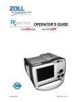
2.2
Observation Monitor
(1) To check the interior of the observation monitor, remove the four
retaining screws (A) which fix the monitor rear cover for the color
15-inch monitor or the two retaining screws (A) and two retaining
screws (B) which fix the monitor rear cover for the color lo-inch
and black/white 12-inch monitors, and remove the monitor rear cover
by sliding it backward.
r
_2==Monitor rear cover
.
b
Retaining
screw (A)
Pull backward.
Retaining screw
(for color IO-inch
and B/W 12-inch
monitors)
Figure 2-2
2-3
No. 2D730-133E*I
(2) To remove the monitor together with the front cover, remove one
looseness-prevention setscrew using a bladed screwdriver (or
hexagonal wrench) and lift up the monitor together with the fork
support.
fAt this time, the cables connected to the rear of the monitor
must have been removed.
Five RGB signals, power cable
:
Color monitor
BNC cable for VIDEO signals, power
Black/white monitor:
connector, GND terminal
\
Lift up.
Front cover --
BNC cable for R, G, 8,
VD, and HD signals
Fork support -
I
setscrew
Figure 2-3
2-4
No. 2D730-133E*I
I
Front cover
AM
Retaining screw (D)
Retaining screw (C)
--
Plate (B)
Brightness
VR
Contrast VR
+
Retaining
screw (E)
Plate (8)
Retaining
screw (E)
(Other monitors)
(15-inch color monitor)
Figure 2-4
(3) To remove the front cover, remove retaining screw (C) or (D).
(When retaining screw (C) is removed, the front cover can be removed
together with plate (A).) At this time, be careful not to
disconnect the brightness and contrast VRs.
(4)
Remove retaining screw (E) to remove the brightness and contrast VRs
together with plate (B) from the front cover.
(5)
To remove the brightness and contrast VRs from plate (B), remove the
knobs and retaining screw (F).
2-5
No.
2.3
2D730-133E
Removing the Main Panel Cover and Main Panel
(1) Remove retaining screw (A) on the bottom of the main panel.
By
removing retaining screw (A), the cover below the handle is also
removed.
Cover below the handle
0
0
0
0
0
0
0
0
Retaining
screw (A)
I'
Q
Figure 2-5
(2) Remove the knob and the concentric VRs of the sub-panel by loosening
the headless screws.
2-6
No.
(3) Remove the main panel
cover by lifting it upward.
Concentric VRs
(3 VRs)
Headless SC
Knob (1 knob
Headless
Figure 2-6
2-7
2D730-133E
No. 2D730-133E
(4) Remove retaining screw (B) at the upper part of the sub-panel to
remove the main panel.
At this time, be careful not to subject the connected cable to
excessive strain. Remove each cable, as required.
Retaini
Figure 2-7
2-8
No. 2D730-133E*C
2.4
Checking and Removing the Power Supply
(1)
To check the power supply, remove the rubber caps (rectangular and
and cable hanger knob to
round), retaining screws (A), (B), and (CL
remove the left side cover.
Remove retaining screw (D) to remove the left brace.
(3) Remove retaining screw (E) to remove the left side shield plate.
(4) Remove retaining screw
(F) to remove the power
shield plate.
(5) After steps (1) to (4)
above have been
completed, the connector
section of the power
supply will be visible
to permit checking.
Cable hanger knob
* Left side
',
shield plate
Retaining
Retaining
0
I
0
0
0
/’
h
d
,
I
c*
.
.
4
Retaining
screw (F)
Retaining
screw (Cl
Retaining
screw (D)
Brace (left)
Figure 2-8
2-9
I i
-Connector
section
of the power supply
No.
2D730-133E"F
(6) To remove the power supply, do steps (1) to (4) and remove rubber
and
caps (rectangular and round), retaining screws (G), (H), (I),
(J) to remove the right side cover.
(7) Remove retaining screw (H) to remove the brace (right).
(8) Remove retaining screw (L).
Retaining
screw (G)
Brace (right)
Rubber cap
(rectangular)
Retaining
screw (I)
Retaining
screw (L)
t
Figure 2-9
Z-10
No. 2D730-133E
Retaining
screw (M)
e
Pull out.
Power supply unit
Figure 2-10
(9) Remove retaining screw (M) and pull the power supply unit out while
sliding it to the left.
(10) At this time, take care with caster direction.
2-11
No. 2D730-133E"F
2.5
Service Work for PWBs
(1) T&R rack
e----------Shield
plate for the T&R rack
-Retaining
screw (C)
Fan plate
Rear cover
r-
Cable hanger
knob
1
PROBE-SEL-PWB
Kubber
cap
Figure 2-11
(a) Remove two cable hanger knobs, two rubber caps, and two retaining
screws (A) to remove the rear cover from the main unit.
(b) Remove 4 retaining screws (B) to remove the fan plate from the
main unit.
* At this time, be sure to disconnect the power CNN of the fan.
(c) Remove 11 retaining screws (C) to remove the T&R rack shield
plate from the rack.
(d) To perform service work on the PROBE-SEL-PWB, remove retaining
screw (D) to remove plate (A) which connects the PROBE-SEL-PWB
and the PULSER-PWB in the T&R rack.
(e) Remove the rubber caps and eight retaining screws (E) on the
side of the system.
2-12
No. 2D730-133E*C
(2) D&D rack
D&D rack shield plate
I
Shield plate
I
Figure 2-12
(a) Remove the five rubber caps and retaining screws (A) (seven in
total) to remove the right side cover from the main unit.
(b) Remove 6 retaining screws (B) to remove the shield plate.
(c) Remove 8 retaining screws (C) to remove the D&D rack shield.
2-13
No.
2.6
2D730-133E
Layout of the Racks
(1) The T&R rack is located at the upper part of the system
(The PWB must be pulled out toward the rear of the system.)
(2) The D&D rack is located at the lower part of the system
(The PWB must be pulled out toward the right of the system.)
Rear view of the system
Right side view of the system
Figure 2-13
2-14
No. 2D730-133E
PWB layout in the T&R rack
,
PROBE SEL
I
Reserved
DVAF/RECEIVER
PHASE DET
Figure 2-14
2-15
No. 2D730-133E*F
PWB layout in the D&D rack
CPURPGITRCONT p
ECG/NONFADE
FFT/CONT/AUDIO
B&W DSC
L
FFT I/O
AK/LB/CAL
IMAGE MEMORY
FIL/CORR
COLOR DSC
I-
MECHA-CONT
MT1 CONT
ENC/DEC
RGB CNV
Figure 2-15
2-16
No. 2D730-133E*D
3.
OPERATION OF EACH PWB
Page
3.1
3-2
T&R Unit_________--- ____________________~~~~~~~~~~~~~~~~~~~~~~~
3.1.1
PROBE SELECTOR ____________________~~~~~~~~~~~~~~~~~~~~~~
3-5
3.1.2
PULSER----------- ____________________~~~~~~~~~~~~~~~~~~~
3-5
3.1.3
R-DELAY--------- ___~________________~~~~~~~~~~~~~~~~~~~~
3-8
3.1.4 DVAF/RECEIVER ____________________~~~~~~~~~~~~~~~~~~~~~~~
3-12
3.2
3.3
3.5
D&I)
Unit
________________
____________________~~~~~~~~~~~~~~~~~~~
3-16
3.2.1
CpU_____________________________________________________3_16
3.2.2
RPG/TRCONT ____________________~~~~~~~~~~~~~~~~~~~~~~~~~~
3-19
3.2.3
PC DSC (B&W DSC) ____________________~~~~~~~~~~~~~~~~~~~~
3-21
3.2.4
IMAGE MEMORY ____________________~~~~~~~~~~~~~~~~~~~~~~~~
3-23
3.2.5
ENC/DEC ____________________~~~~~~~~~~~~~~~~~~~~~~~~~~~-~
3-26
FFT Unit ____________________~~~~~~~~~~~~~~~~~~~~~~~~~~~~~~~~~~~
3-29
3.3.1
PHASE DETECTOR ____________________~~~~~~~~~~~~~~~~~~~~~~
3-31
3.3.2
FFT I/O ____________________~~~~~~~~~~~~~~~~~~~~~~~~~~~~~
3-33
3.3.3
FFT/CONT/AUDIO ____________________~~~~~~~~~~~~~~~~~~~~~~
3-35
3.4.3
MT1 CONT ------------- ____________________~~~~~~~~~~~~~~~
3-43
COLOR DSC Unit ________________________________________~~~~~~~~~3_45
3.5.1
PC DSC (CFM DSC) ----_---________________________________3_45
3.5.2
RGB CONVERTER ____________________~~~~~~~~~~~~~~~~~~~~~~~
3-47
3.6
ECG/NF ________________________________________~~~~~~~~~~~~~~~~~3_50
3.7
Color Enhancement ____________________~~~~~~~~~~~~~~~~~~~~~~~~~~
3-l
3-52
;3---
No. 2D730-133E
3.1
T&R Unit
(1) Outline
The T&R unit consists of the components below:
o Transmission circuit system which emits ultrasound
from the probe
The transmission circuit system has a 48 channel pulser for normal
tomographic images (B/M mode), PW Doppler (FFT), and color Doppler
(CFM).
o Reception circuit system which processes the signals received on
the probe
The reception circuit system includes a reception circuit (Echo
Filter, Log Amp, wave detection, etc.) for B/M mode and a phase
detection circuit for FFTjCFM.
(2) Flow of signals in the T&R unit
(a) Transmission circuit system
Transmission delay data which has undergone arithmetic
operations in the CPU is transferred to BRI RAM on the
RPGjTRCONT PWB. Delay data which has been transferred undergoes
arithmetic operations for raster interpolation in the arithmetic
operation section. Then, 48 channels of data are transferred to
the PULSER via the data bus during the rate blanking period.
The T DELAY gate array IC on the PULSER PWB uses the 48 channels
of data to count the number of TCK waves (10 MHz, 12 MHz, and 15
MHz burst waves) generated in the RPG/TRCONT and outputs the
trigger signal for transmission after the period of time
The high voltage (DC) is
specified by the delay data elapses.
converted to high-voltage pulses on the PULSER using the signal
to drive the transducers in the probe from the free-edge coaxial
flat cable via the high-voltage switch (HVSW) on the PROBE
SELECTOR PWB.
(b) Reception circuit system
The echo signal received from the transducers is amplified by
the PRE AMP on the PULSER PWB via the high-voltage switch on the
PROBE SELECTOR PWB. In order to avoid saturation in the
succeeding circuits due to close intense signals, the gain is
controlled in the PRE AMP with respect to time (depth). The
gain control signal (PRE STC signal) is generated in the PRE STC
CONT circuit on the DVAFIRECEIVER PWB.
3-2
No. 2D730-133E*F
The output signals from the PRE AMP are delayed and added
through the DELAY LINE on the R DELAY PWB so that the wavefronts
of echo signals from the 48 channels can be matched for
deflecting and focusing the reception beam. Because focusing
during signal reception is performed dynamically, two systems of
R DELAY PWB output signals are selected using the DVAF SW so
that DELAY LINE tap setting noise is not mixed in. The data
which sets the delay time through the DELAY LINE on the R DELAY
PWB is generated in the same manner as for transmission data and
transferred to RAM on the R DELAY PWB. The data is transferred
during each DVAF interval via the two bus systems (RDLDB).
-3,
Then, the DVAF output signal from the DVAF/RECEIVER PWB is'
transferred to the RECEIVER circuit for B/M display and to the
The signal which has
PHASE DETECTOR PWB for FFT/CFM display.
been. transferred to the RECEIVER circuit has its central
frequency changed via the band-pass filter with respect to time
(depth) in the ECHO FILTER circuit, the resolution and S/N ratio
is improved, wave detection and gain adjustment are performed in
the DETECTOR via the LOG AMP, and the signal is output to the
D&D unit. Gain adjustment is performed by the STC signal
generated from the CPU PWB in the D&D unit.
The signal transferred to the PHASE DETECTOR PWB is amplified in
the AGC/PRE AMP via the SELECTOR and phase detection is
performed through multiplication by the Doppler Reference signal
in the MIXER circuit. The output signals are divided to feed
One is the ATT circuit for FFT, and the other
two destinations.
is the ATT circuit for CFM. Amplitude adjustment is performed
in both ATT circuits. The signal for FFT is transferred to the
FFT unit and the one for CFM to the CFM unit. For detailed
explanation of the PHASE DETECTOR PWB, refer to 3.3 FFT Unit.
(c) Differences from the EX series (a series)
The basic technologies of each PWB in this unit are the same as
those of the EX series. To integrate the same functions into a
single compact PWB, the density of components mounted on the PWB
surface is increased using surface mounting technology for
components except for the R DELAY PWB.
The PROBE SELECTOR PWB is newly designed based on that of the
SSA-240A to support switching of three transducers with a
granddaughter board incorporating the HVSW and transducer
connector section. This PWB cannot be interchanged with the old
For transducer C
PWB supporting switching of two transducers.
(optional), an electronic scan transducer or an annular array
sector transducer can be connected by replacing two kinds of
granddaughter board.
The PULSER PWB is based on that of the SSA-240A with partial
change in circuit and newly designed pattern to upgrade the
The R DELAY PWB is based on that
manufacturing characteristics.
of the SSA-270A with the connectors changed to DIN connectors.
The DVAF/RECEIVER PWB is based not only on the OFFSET DELAY PWB
of the SSH-140A with partial change in the DVAF SW circuit and
PRE STC CONT circuit onto which components are mounted using
surface mounting technology but also on the RECEIVER PWB common
to the EX series, onto which components are mounted using
surface mounting technology, with partial circuit change.
3-3
;3----_
No. 2D730-133E*J
THIS PAGE IS LEFT BLANK INTENTIONALLY
3-3A
*
No. 2D730-133E*F
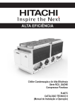
3.1.1
PROBE SELECTOR
(1)
Outline
(a)
The standard configuration includes the daughter board and two
granddaughter boards for electronic scan transducers.
The
granddaughter board for the electronic scan transducer or the
granddaughter board for the annular array sector transducer
can'be selected as an option for switching of three
transducers.
W
Selects the transducer corresponding to the specified raster
for each rate. Switches between two transducers for the PWB
supporting two transducers (three transducers for systems
incorporating an option).
cc> Provides
probes incorporating an impedance converter with
direct bias voltage.
W
Turns OFF the high-voltage relay when high voltage leaks to
the ultrasonic signal line or when a probe ID is not
identified correctly. At this time, the system stops and
ERROR is displayed on the monitor.
(4
If a resonance transducer is connected by mistake, the highvoltage relay' is turned OFF and system operation is
terminated.
(0
Connects motor control signals from the MECHA-CONT PWB to the
annular array sector transducer.
(2) Figure 3.1-2 shows a block diagram.
3.1.2
PULSER
(1) Outline
(a> PULSER
This circuit electrically drives the transducer inside the
probe, and outputs high-voltage pulses set by VH according to
the TRIG signal described below.
W
PRE AMP
Preamplifies the echo signal from the transducer with a gain
corresponding to the external control voltage (PSTC) (t6 to
t30 dB, -18 dB when CH is OFF with variable aperture used).
(c)
T-DELAY/CONTROL
Outputs the TRIG signal to excite the PULSER by providing the
pulse width, the number of burst waves, and the delay time set
by MTCKO and TRDB.
Cd) The functions above are performed for 48 channels per PWB.
(2) Figure 3 .l-3 shows block diagram.
3-5
PBlPF
~~~~~_~_~~~__________________________,
POUT1-48
A
Granddaughter board
i
j
‘I
HVSWD,
HVSWLE
HVSWCK
HYSWCL
7
CONT
section
I
iPROBE
1
00
VPLEAKJ
,v4
‘SELA-C
z-CONV
power
)
PBIDO-7,
V l,VZ,V3
,
circuit
\
~~~~-~~~~~~~~~~~~~~-~~~--~~~~-~~~~---~
~PROBE B Granddaughter board
iI
II
:
I
: Hvsw
8
@@@
,48
\
, 20
I
-
I
-
I
I
I
cl-c PROBE
TESTER
circuit
I
w
m
/
cy22
Id
\
II?
L
w
(wA-9yQWl
@@
I
-o\r>PROBECNN
;
I
,I
k 128CH
I
4
I
,I
:_______,_,,,_,,,_,,,,,,.,,,_
VPrEAI$
, 1
I
h4PBEN-BO
PBIDO-‘I ,.
\
,c 8
V l,VZ,V3
:;,‘==-=‘========,=‘=,=‘===,‘=_=-’==-’=====~~~~
I
::
iiPROBE C Granddaughter board
.
-
PROBECNN
I
I
\
1
VPLEK
-
v
/
(xx)
VPLEAK
PBIDO-7
I, 3
C-N
/\
detection
c
o
-
MPBEN-CO
Vl,VZ,V3
POuTrNHl
@
Error
output
@
‘::::.!: indicates option.
o indicates the page of the circuit diagram.
Figure 3.1-2
ji
. or48CH
,l
,
High-vottage
leak
detection
+
:I
.I
;I
::
* :!
ii
4
,::
L___e___
_____-__ ___
___._a- __e___e_-_yA;
s_____
_____._____._
,,,_-_,,.z:
;)
0
I
L
vPNRE-soo
-(iGCK-)
Block diagram for the PROBE SELECTOR
CWA4
No.
3.1.3
2D730-133E
R-DELAY
(1) Function
(a) After providing delay time to echo signals PECHO 1 to 48,
which are the outputs from the preamplifier inside the pulser
PWB, according to the appropriate focus pattern, addition is
performed to obtain the RDLECHO addition output signal.
(b) Performs switching between ON and OFF of the preamplifier
output signal given by the receiving element to permit
reception aperture control.
(c) Using two PWBs, 48-element DVAF operation is performed:
Rl
R2
1 to 48 ch
1 to 48 ch
Focus 1, 3, 5
Focus 2, 4, 6
(Odd numbered stage)
(Even numbered stage)
These PWBs perform the above functions.
divided into the following blocks:
They can be roughly
o Input buffer and short delay block
o Multiplexer block
o Long delay block
o DVAF SW block
o Control block
(2) Multiplexer
block
(5) Control block
/
3-8
No. 2D730-133E
(2) Operations
(a>
Input buffer and short delay (TD62505P + AVZO39-01)
PECHO 1 to 48 has a DC bias of about 6 V. It is supplied to
the array transistor TD62505P (OL through W) near the PWB
Plug' The output from the array transistor is supplied to the
short delay SMC (SDL SMC), and then passes through a delay
circuit (0 to 315 ns in 15 ns steps). SDL SMC (AVZ039-01) has
15 ns and 300 ns (30, 60, 120, 180, 240, 300 ns) delay lines,
and selects one of them to perform a variable delay function.
(W Multiplexer
(PM30-21299)
The signal sent from SDL SMC is fed to MPX SMC (PM30-21299).
MPX SMC is provided with a matrix type switch, and connects
the 1 to 48 ch signal to one of the 16 taps. Thus, each MPX
SMC can select among 8 channels x 16 taps. Out of 16 taps,
8 taps of output are used. However, the output from MPX SMC
is a current output. Thus, it cannot be checked using the
voltage probe.
(cl
Long delay block (DLlO to 16)
The signal (Sl to S8) sent from the multiplexer corresponds to
the tap input for the long DL. It is fed to the emitter of
the base grounding circuit for TRl through TR8. The collector
is fed to the long DL having taps with 300 ns steps, resulting
in a selectable delay of 300 ns x 7 taps = 2100 ns. As shown
in the block diagram, the long DL consists of the seven 300 ns
delay lines. A buffer is installed between these delay lines
to compensate the frequency and delay characteristics.
00
DVAF SW block
Echo to which delay is added by the long DL block passes
through HPF, and is sent to DVAF SW. The DVAF SW block
utilizes FET SW, and provides differential output to enable
dynamic delay control in which noise is suppressed.
In
addition to this, the output is sent to the DVAF/RECEIVER PWB
through a separate line in order to provide a wide dynamic
range when the DVAF is OFF.
k>
Control block
Control block consists of two blocks, write control and read
control blocks through FIFO.
3-9
No. 2D730-133E
(e-l) Write control block
The figure below shows the timing for input data and clocks.
The input data is the delay data quantized at 4 ns. The bit
allocation is shown in the figure below. The input data is
latched, and then sent to the sing-around ROM. The singaround ROM is so programmed that the tap most suitable for
The ROM is not
the input data may be selected.
interchangeable with the other RDL PWB. Thereafter, the
data is accumulated in FIFO.
(Positive logic on bus)
RDLDB
11 10
9
7
8
6
5
4
3
210
0
0
011
Delay
amount (PS)
0
1
0
0
0000000
0
0
0
0
0
0
0
0
0
0
0
0
0
0
0
0
0
0101
8
0
0
0
0
0
0
0
0
0111
12
010
RDLDBO
0
10110
0
0
1
4
01
Disables reception
Enables reception
.
.
2400 ns
0 . . . flL"level
1 . . . t'Hnlevel
i
(e-2) Read control block
Accumulated data are read from the FIFO according to the
read clock. The data written in the previous DVAF data
transfer period is read from the FIFO at one time.
3-10
No. 2D730-133E
THISPAGEISLEFTBLANKINTENTIONALLY
3-10A
No. 2D730-133E
3.1.4
DVAF/RECEIVER
(1) Outline
the DVAF SW circuit,
This PWB comprises three types of circuits:
The circuits
and
the
PRE
STC
CONT
circuit.
the RECEIVER circuit,
PWB
using
surface
mounting
are implemented on a single Kl-size
technology.
(2) Functions
(a) The DVAF SW circuit performs DVAF switching of echo signals
transferred from the R DELAY PWB. The DVAF switching function
is performed with a preceding SW on the R DELAY PWB and a
The
succeeding SW and a control circuit on the DVAFIRECEIVER.
control circuit controls the succeeding and preceding SWs.
(b) The PRE STC CONT circuit generates the gain control signal of
PRE STC to control the gain of the PRE AMP incorporated in the
This signal has
PULSER PWB in synchronization with the RATE.
four types of curve to prevent saturation at close range.
(c) The RECEIVER circuit receives the output signal from the DVAF
circuit and outputs the ultrasound VIDEO signal. Each circuit
block is described along the flow of the signal.
(c-l) HPF
Improves the lateral resolution by eliminating low
frequencies to improve the image quality when a highfrequency probe is used.
(c-2) Circuit for eliminating radio frequencies
This circuit consists of two passive band L-C parallel
elimination filters and eliminates noise from a radio
station, etc. For the adjustment procedures, refer to
(7. ADJUSTMENTS).
(c-3) Echo filter circuit
This circuit consists of six BPFs in series in which HPF
and LPF use variable-capacitance diodes and of HPF fixed
by L and C.
This can be changed from 2 MHz to 12 MHz continuously by
controlling the voltage.
3-12
;a=
No. 2D730-133E*H
(c-4) System noise elimination circuit
The circuit is the same as the radio frequency
elimination circuit. It mainly eliminates CK noise of
the DSC unit.
(c-5) LOG AMP circuit (logarithmic amplifier)
This circuit uses a LOG IC consisting of 4 logarithmic
compressors in series. Each compressor is a 30 dB
logarithmic compressor and the series of 4 compressors
provide a 120 dB logarithmic compressor.
(c-6) Detection/O V limiter circuit
Both-peak detection is performed in the detection
The STC signal
circuit which consists of transistors.
is added before wave detection for abdominal examination
processing, but the addition voltage is fixed to 0 V for
cardiac examination processing.
(c-7) Circuit for envelope detection
(LPF)
This is a L-C LPF which eliminates carrier components
from the echo signal and detects the envelope.
(c-8) Edge enhancement circuit (E.E.)
The degree of edge enhancement is switched by the
setting of E.E. in B mode of abdominal examination
processing.
The echo signal always passes this circuit
to perform a certain degree of edge enhancement in M
mode. However, the echo signal passes through this
circuit (without functioning) in B mode for
cardiovascular examination processing.
(c-9) Dynamic range circuit
-
(c-10)
This circuit consists of two inversion amplifiers and
adds the STC signal to the first amplifier for
It sets the
cardiovascular examination processing.
dynamic range by switching the succeeding input resistor
using an analog switch.
Echo enhancement circuit (AGC)
For observing the heart, etc., this circuit feeds back
intense echo signals near the wall with a certain time
constant. This switches the degree of enhancement by
the setting of E.E. in M mode and B mode for
cardiovascular examination processing.
(c-11) Control circuit
This circuit latches the data bus PCRDB (8 bits) during
the rate blanking period and sets data and control for
each circuit.
3-13
:a--_
No. 2D730-133E*H
(c-12)
STC control circuit
This circuit receives the STC signal and switches the
point at which the STC signal is added by the setting
of abdominal or cardiovascular examination processing.
Gain conversion of STC voltage is 0.5 V/l0 dB.
(3) Differences from the EX series
The DVAF SW circuit is based on the structure of the SSH-140A.
The RECEIVER circuit is
The adjustment circuit is changed.
implemented on the RECEIVER PWB common to the EX series using
surface mounting technology; for the LOG AMP only, however, the
LOG AMP on the circuit of the SSA-220A is used and the number of
adjustment VRs is reduced. The PRE STC CONT circuit is based on
the saw-tooth wave generation circuit of the OFFSET DELAY of the
SSH-140A; however, three types of depth-to-sensitivity curves, by
which the close range sensitivity is made lower than 140A, are
added.
3-14
;3--_
~------------------------------,,,,,
’
-__-__--___-________---
___--a___
2MW3@14773
r
--___-,r--------y-_“__‘_____--;
l--zL-_L_V’LV_____________f
1L.,l,-lfi
..-?-?-I
I
1
1h-r” -1I-.-
1
u-3
--_______-__
____--______
TlY”,1l-lx0
Q !i
2MW30-14774,2MWJO-14780
; Echo filter circuit
pw30-14779
----______
I
STC control circuit
I
I
DECHO
IJB3
UC-3
m-m-
I
---__
I
I
I
I
I
I
--____
I
I
I
1
I
2MW30-14771
I
ii;;_____
I
I
11‘-1
--
QTPR23
’
@~~~,,
_
I_
!%
-__________
~tc?l%$&To$c~i%%
AI
‘;
. ..- . . , II\T\,LI
:wB-2a.
PCRLCK70
w%5
iI&4
~27” PCRDB70
I
I
111
+O V linibr
I
’
to 00
iE2:
ADJUST0
\I
WC-18
STRCWONI
1,
/~~r~i~----~~~-----T~R~~------~
I
WC-6
,
; 2MW30-14775
4
I
m.---------------~
j’i,
I- ------------________~~~~~~~~~~~~
I
I
I
I
I
Echo
enhancement
circuit
I
/
I
I
I
J
I
, ------------________~~~~~~~~~_
2MW3C-14777
2MW30-14778
PSTC1
LATCH
____________________-----_
Figure 3.1-5
-----,J
Block diagram for DVAF/RECEIVER
;
I
I
,
I
I
I
I
I
No. 2D730-133E
3.2
3.2.1
D&D Unit
CPU
(1) Outline
(a) Function
This PWB consists of the following four different blocks and
functions.
a. Host CPU section which controls each unit using a 68000
microcomputer which has a wide address space and low power
consumption.
b. PANEL I/O section which controls the interface with the
panel.
C.
TV-SYNC GEN section which generates the TV sync. signal.
d. STC waveform generating section
b) Description
of operation
a. Host CPU section
Performs the following control using the control program
stored in EPROM and preserves preset data in EEPROM.
Performs arithmetic operations and processing in SRAM as
work area and controls each unit.
Controls the graphic LSI (~PD72020) to display marks etc.
on the monitor.
Receives interrupts from each unit and processes the
interrupts.
Controls the timer IC.
Controls the RS-232C interface IC.
b. PANEL I/O section
The following information is transmitted and received
between the host CPU and the panel.
o ON/OFF information of the SW and LED
o Information concerning the amount of shift of the
trackball and rotary encoder.
o SCAN IC control information
C.
TV-SYNC GEN section
Generates the read clock in the TV horizontal direction and
generates the TV signal in synchronization with the graphic
signal of the host CPU.
3-16
:3--_
No. 2D730-133E
d. STC waveform generating
section
Performs A/D conversion of the voltage value of each STC
slide control on the panel, performs horizontal
interpolation, generates data for STC waveforms, adds the
preset STC value, gain, gain correction value transferred
from the host CPU to the data, and performs D/A conversion
to generate the STC waveform.
3-17
No. 2D730-133E
SKAM
Ll(256 KB)
I
1
Ex-
ternal
I/O
I
GENERATOR
GA
TV SYNC SIGNAL
r
I
-
l
Gain
correction
STC
RAM
GA
+generatingRAM
(transmission)
1
-Gain
1
correction
Era%
(reception)
Figure 3.2-l
CPU block diagram
3-18
No. 2D730-133E
3.2.2
RPG/TRCONT
(1) Function
This PWB consists of the RPG section and the T/R CONT section.
In the RPG section, the functions to generate the following
signals to be the basics of the system are provided.
(a) Basic clock signals
(b) Basic rate of ultrasound
(RATE, OF) and sample enable signals
(c) Raster address signals of ultrasound
In the T/R CONT section, the following functions are provided to
control each PWB in the T/R unit.
(a) Generates and transfers transmission/reception
DELAY data.
(b) Generates and transfers transmission/reception
aperture data.
(c) Generates and transfers the control signals of the highvoltage endurance switch and the reception echo signal
processing circuits, (the GAIN control circuit of PREAMP, ECHO
FILTER circuit, DYNAMIC RANGE/ECHO ENHANCE circuit, etc.).
(d) Generates the control signal for progressive dynamic focus
(e) Generates the transmission basic clock signal.
(f) Generates the control data in the high-voltage
power supply unit.
(2) Figure 3.2-2 shows a block diagram.
3-19
circuit in the
iD=
No. 2Df30-133E"G
3.2.3
PC DSC (B&W DSC)
(1) Function
This DSC is a single PWB into which the upgraded versions of the
DSC-I/O and DSC-FM functions of the EX series are implemented.
(a> Digitizes the analog echo signal output from the RECEIVER PWB
at 15 MHz (ADC)
(b) Vertical Smooth Filter processing
(Digital Filter)
w
Input/output of data to/from the IMAGE MEMORY PWB
W
Lateral Filter processing
W
Constructs B/W images by Frame Memory
B mode:
M mode:
(FM-IN SC)
Performs Frame Correction processing if there is not
the IMAGE MEMORY PWB.
MAX Sample processing
w
LIP processing while reading Frame Memory (FM-OUT GA)
w
Post-processing while reading Frame Memory (Gamma RAM)
00
Outputs the B/W Composite Video signal (DAC) +
(i)
Outputs the B/W Digital image signal
+
ENC/DEC PWB
RGB-CONV PWB
<j> Generates the Test signal
Note:
Operation is performed using the Test Pro. However,
the Data Set by the following patch menu can be also
used.
a:DSC-Test Pattern
Address:200006
Data:OOAE or OOAC
b:LIP-Test Pattern
Address:200006
Data:OOB4 or OOA4
(2) Differences from the EX-DSC
(a) Vertical Smooth Filter processing
(Digital Filter)
(b) Speeds up Frame Memory writing
(c) Constructs Frame Memory directly corresponding to TVl, TV2
(d) FFT Data is input in digital form
3-21
A
w
N
N
-
-I
Figure 3.2-3
Block diagram for PC DSC
n
No. 2D730-133E
3.2.4
IMAGE MEMORY
(1) Function
(a) Records and plays back the B, BDF images (loop, frame advance)
(b) ECG synchronized recording
until freeze)
(records the images from R-DELAY
(c) Frame correlation of the B, BDF images
(d) Displays the interpolation image of CFM smoothing
(2) Main specifications
(a) Record, playback mode (differs from the EX)
Recording:
Playback :
Loop, ECG synchronization
Loop (Slow playback is possible.), Frame advance
* The pseudo bi-plane playback function, B LOOP HIGH FRAME
function, four-frame edit function, and the recording and
playback functions of M/MDF are not available.
(b) Memory capacity (same as the EX)
B 32 Mbit
(maximum 127 frames; differs depending on the number of rasters)
BDF 32 Mbit
(maximum 63 frames; differs depending on the number of rasters)
(c) Frame correlation
(differs from the EX)
12 types each for B, BDF (specified by the IP)
(d) Circuit.method
(differs from the EX)
Control by the local CPU (280)
Implementation of the frame correlation processing circuit
into an ASIC
One PWB for black/white and color
3-23
No. 2D730-133E
(3) Functions by circuit block
(a> FC-1, FC-2
Performs frame correlation.
(b) B/W-MEMORY
B-mode image memory
32 Mbit = 512 k x 8 bits x 8 blocks
cc> COLOR-MEMORY
32 Mbit = 512 k x 16 bits x 4 blocks
BDF-mode image memory
Cd) DATA SELECTOR
Selects data corresponding to the specified frame NO. from the
memory block.
W
SAMPLING CONT
Controls the starting point for data fetch with respect to the
RATE signal.
Composes image using the combination focus.
(f> MEMORY CYCLE GEN
Generates the timing signals such as RAS/CAS of memory
(0
ADDRESS GEN
Generates the address data of memory
W
(DRAM).
(DRAM).
HOST-CPU-IF
I/O port of the host CPU
W
MAIN-CONT
Receives commands and data from the host CPU and controls
recording, playback, and frame correlation in the 280.
3-24
IMAGE MEMORY
-BDSC
1 1
DSCBFRZO
j
/
1
(IMDSCOO to 230
(
_
,
.
I
.
I
.
IDSCIMOO to 230;
>
>
B/WMEMORY
FC-1
FC-2
\
\
v
I
7
\
HOST
-CPU-IF
>
COLORMEMORY
IOSEL80
RESET0
EIORDLO
EIOWRLO
EAlO to 70
ED00 to 150.
\
DATA
SELECTOR
>
>
r\
F\
I
I
\
.
\
MAIN-CONT
&OF0
ECGFRO
ADCCKl
NEWRATEO
4
MEMORY
CYCLE
GEN
>
ADDRESS
GEN
>
SAMPLING
CONT
,
b
ECG/
NONFADE
Figure 3.2-4
Block diagram for IMAGE MEMORY
.
*l BRASTCKl
DRATEl
DOFO
BSAENO
2
l
5
s
i-J
K
M
No. 2D730-133E*B
3.2.5
ENC/DEC
This PWB has the following functions to output each type of video
signal to the observation monitor and peripheral video devices.
(1) Function to switch the input of the video signal (VIDEO SELECTOR)
o Selects the input signal using the data set to the I/O PORT
according to the panel SW (menu operation).
o Outputs the color DSC output as the RGB signal in the color
system in INT mode. At this time,. the.black/white DSC output is
output as the black/white video signal for which "positive" and
"negative" have been selected.
;3--o Selects "positive" and "negative" to output the black/white DSC
output as the black/white video signal for the black/white
system in INT mode.
o The VCR playback signal, for which the input has been selected
between the SVHS and VHS using the toggle SW on the VCR panel, is
input. The PAL version does not support the VHS input signal.
o The EXT-RGB signal is the input signal for which EXTl (printer)
or EXTZ (MO etc.) has been switched on the EXT CNN PWB.
(2) Function to separate/select the synchronization signal according
to the selection of the input signal (SYNC SEP/SYNC SEL)
o Selects and outputs the synchronization
when the DSC output is selected.
signal of the system
o If the VCR or external device (C-VIDEO output) is selected, it
separates CSYNC, HD, VD from the video signal before output.
o If the EXT-RGB signal is selected, it separates CSYNC, HD, VD
from the EXT CSYNC before output.
(3) Encoder
(RGB +
S-VIDEO (Y/C), S-VIDEO (Y/C) +
C.VIDEO)
o Converts the RGB component signal to separate video - Y/C.
o Converts separate video - Y/C to a composite video signal.
(Y = brightness signal t synchronization signal,
C = chroma (color difference) signal)
(4) Decoder
(C. VIDEO -+ S-VIDEO, S-VIDEO +
RGB)
o Separates the composite video signal into separate video - Y/C.
(The PAL version does not support this function.)
o Converts separate video - Y/C into the RGB component signal.
3-26
No. 2D730-133E*B
(5) Outputting the video signal
o Three types of RGB output
(color monitor/EXT-RGB
EXTl, EXT2 at EXT CNN)/AUX-RGB)
(separated into
o Separate video - Y/C
o Composite video signal for the VCR
o Two types of black/white video, (black/white monitor, B/W VIDEO
(separated into EXTl, EXT2, EXT-B/W at EXT CNN))
o SEL-VIDEO (switches the black/white signal and color signal with
the toggle SW on the rear panel in INT mode.)
Color DSC output
(RGB)
Black/white DSC output (POSI)
(NEGA)
VCR output
External RGB
External C.VIDEO
(SVHS)
(VHS) (Note)
Switches the input video signal
Menu selection, Toggle SW selection
Separation/selection of the
synchronization signal
When the input is S-VIDEO, C-VIDEO,
the C.SYNC, HD, VD signals are
separated.
Video signal conversion
Encoder (RGB + S-VIDEO,
S-VIDEO + C.VIDEO)
Decoder (C.VIDEO + S-VIDEO,
S-VIDEO + RGB) (Note)
Output buffer
For color observation monitor
For EXT devices (MO, PRINTER, camera, etc.)
For AUX (multi-imager etc.)
S-VIDEO S-VHS
C-VIDEO VCR-VBS
Black/white observation monitor
B/W OBS
B/W VIDEO (B/W MO, B/W camera, printer, etc.)
RGB
SEL-VIDEO Switches black/white and color using the toggle SW.
Note:
The PAL version does not support the VHS input signal.
3-27
._._._._._._.B/voBs
_._
i+=Jj-l
*
,___________~._‘_____‘-‘“-“““”
I
,
I
.___
____----:--_ _
__--e
d
t
t
I
I
-
:
:
(_
e-2
yBs
-
-sell
axm
DSC
m-R3B
-
Y/c --ii
Y/c
EL
P
MC Y/c
:
-
U’tM’ER) .--
EXT2
(MO) .------1
I
Remarks:
Note
:
HCUITOR-m
---
I
Mounted on the EXT CNN PWB
The PAL version does not support the VHS input signal.
Figure 3.2-5
m
oes MONITOR
WD.WC!MC)
txtfalh-RQI
hmm--
wD,w.csYw
EXTl
1
4
q
SEP
*
:
EKC VBS
I=
D
_
S-VHS
T()R
a
I
!____.l
Y/
_
WI-Y/C
MONl
Block diagram for ENC/DEC
REAR-RGB
(rmtTI-ItMZR)(C5W3
No. 2D730-133E*F
3.2.6
MECHA-CONT
(1) Functions
The following operations are performed during annular array sector
scanning.
(a) In B mode, the scanning speed is controlled.
(b) In M mode, the piezoelectric
angle.
element is fixed at the desired
(c) In B mode, the data indicating the raster address and the
In addition, the
transmission focal point are generated.
fundamental signals BATE and OF are generated.
(d) The zero point of the transducer is adjusted.
(2) Description of operation
This PWB controls the motor of the annular array sector transducer
using a CPU (280). The motor rotation speed is obtained by
measuring the pulse period of the output of the encoder attached
to the motor.
In B-mode scanning, to make the raster density more uniform,
feedback control is performed so that the motor rotation speed is
faster at the scanning center and slower at the edges.
The base voltage at which the amount of feedback is reduced is
determined beforehand and the feedback voltage is calculated from
the difference between the motor rotation speed and desired speed.
This voltage is added to the base voltage and supplied to the
motor.
The motor rotation angle is obtained based on C-phase and B-phase
pulses of the encoder. From these signals, the raster address
corresponding to the scanning angle, the transmission focal point
data, and the fundamental signals RATE and OF are generated.
In M mode, the piezoelectric element is fixed at the angle
corresponding to the M address by obtaining the rotation angle
from the A, B, and C phases.
3-28A
ROTARY
ENCODER
T
ENC
A
1I
AS I C(MECHA)
1
B
C
I
-
I
-
I
READR31I
F’LIER
BUFFER
SELECTOR
HII
Q
El
IF-III
11ZADJSl
I-
F====
MECHA
II
MSRPO
..C.-.
.
I
I
\
L
I ’
CLOCK
CEN
1
7
I
Oscillator
Figure 3.2-6
NECHA-CONT PWB block diagram
DRlVER
MDA
MOTOR
No. 2D730-133E
3.3
FFT Unit
(1) Function
This unit has the following four functions:
(a) Extraction of Doppler signal PW
(b) Frequency analysis by the FFT
(c) Output of Doppler sounds which are forward/backward
separated
(d) Control of PHASE DETECTOR as well as the unit itself
The FFT unit consists of the following two boards:
o FFT I/O
o FFT/CONT/AUDIO
(2) Operations
The FFT unit receives the phase-detected sine and cosine signals
(from the PHASE DETECTOR board). The Doppler signals of the target
test part in accordance with the range gate are sampled and held,
the low-frequency component is cut off by the Doppler filters, and
frequency is analyzed with the FFTs.
The signals undergo FFT conversion through butterfly arithmetic
operation in the FFT section, undergo square addition to obtain the
power spectrum, perform LOG conversion, and the spectrum output is
obtained.
For separation of Doppler signal directions, the FFT unit shifts the
outputs of the Doppler filters so that they are 90' out of phase with
each other, performs analog operation on the output (for direction
separation), amplifies the result with the audio amplifier, then
outputs it to the loudspeakers.
(3) Differences between the FFT unit of the SSA-340A and the FFT unit of
the EX-series equipment
(a) In the FFT I/O PWB, the existing PWBs, including the granddaughter PWB, are implemented in a single PWB using surface
mounting technology for components.
(b) For the FFT/CONT/AUDIO PWB, the existing three PWBs: FFT PWB,
AUDIO&M
PWB, and FFT CONT PWB are integrated into a single PWB
by implementing the FFT arithmetic operation section in an ASIC
and using surface mounting technology for components.
3-29
No. 2D730433E
THISPAGEISLEFTBLANKINTENTIONALLY
3-29A
No. 2D730-133E
3.3.1
PHASE DETECTOR
(1) Outline
This PWB inputs the received ECHO which has been added using the
DVAF SW on the DVAF/RECEIVER PWB, performs quadrature wave
detection, and outputs the output to the CFM UNIT, FFT UNIT.
(2) Function
The PHASE DETECTOR has the following functions, roughly divided as
follows.
(a> Performs amplitude limiting of the input ECHO signal.
(INPUT LIMITER)
lb)
Eliminates noise in the non-required
bandwidth.
w
Performs quadrature wave detection.
(MIXER)
(BPF)
(d) Eliminates higher harmonics generated by wave detection.
UJPF)
W
Performs gain setting according to the echo level of the PW.
(PW ECHO LEVEL)
(0
Performs gain setting according to the echo level of PW and
(CFM ECHO LEVEL)
the color gain knob on the panel.
(CFM ECHO LEVEL is affected by the PW ECHO LEVEL.)
(8) Generates the test signal.
3-31
(TEST)
---
___------
I
from
DVAF/
RECEIVER>
PWB
Echo
,
signal 1
4
1
INPUT
>
I -+ LIMITER
B.P.F.
I
I
.
Quadrature
> wave
detection
W)
.
>
L.P.F.
6
wu
Control1
signal I
I
Bus
I
signal I
1
L --------
Figure 3.3-2
’
1
,
I
from
FFT/CONT/>
AUDIO
PWB'
1
--e-w
-------
-------w-e----
3
CFM
ECHO
LEVEL
-
RCFM
I ICFM
I
I
(P3)
I
1
>
CONT
(P5)
_--_--------m-e
Block diagram for PHASE DETECTOR
I
--m---------m-
J
DRAWING No. 2MW30-10132 to 10137
to the CFM unit
'(ADC/LB/CAL PWB)
No. 2D730-133E
3.3.2
FFT I/O
(1) Outline
This PWB performs extraction, filtering, gain setting, and A/D
conversion of signals in accordance with the range gate position
in PW mode.
(2) Function
The functions and the outline of the operation of this PWB are
described below. Abbreviations enclosed in parentheses indicate
the name of the block which contains the function.
(a) Detecting the Doppler signal in a certain region using the
range gate in PW mode (S/H)
This integrates the Doppler output signal of the PHASE
DETECTOR PWB based on the control signal (RGATElO, S/HPlO,
RESETPlO) output from the FFT/CONT/AUDIO PWB at the range gate
timing and samples and holds the signal.
(b) Removing clutters (HPF)
Receives the data for cut-off frequency and for the number of
orders via the 280 I/O port and eliminates clutter.
(c) Eliminating noise in the non-required
region (PW LPF)
Receives the data for cut-off frequency (changes depending on
the PRF and mode) via the 280 I/O port and eliminates clutter.
(d) Amplifying the Doppler signal (FFT GAIN)
Changes the degree of amplification in 2 dB steps within the
range from -4 to 30 dB according to the Doppler gain knob on
the panel.
(e) Performing analog to digital conversion of the Doppler signal
(FFT-ADC)
This consists of the S/H, BUFFER, and ADC and performs A/D
conversion of the Doppler signal based on the timing signals
(ADCCONVO, ADCLCKO) output from the FFT/CONT/AUDIO PWB.
(f) Outputting the audio Doppler signal (AUDIO BUFFER)
This consists of a -14 dB non-inversion amplifier and the
output is sent to the FFT/CONT/AUDIO PWB and used as the audio
Doppler signal.
3-33
No. 2D730-133E
THISPAGEISLEFTBLANKINTENTIONALLY
3-338
No. 2D730-133E
3.3.3
FFT/CONT/AUDIO
(1) Outline
This PWB receives the control signals from the CPU PWB, RPGITRCONT
PWB and controls the interior of the unit and the PHASE DETECTOR
PWB. It also undertakes FFT arithmetic operation of the Doppler
spectrum and audio outputs.
(2) Function
The functions and the outline of the operation of this PWB are
described below. Abbreviations in parentheses are the name of the
block which contains the function.
(a) Generating the control signal and timing signal of the FFT
unit (CONT)
o It has a CPU (280) for controlling the FFT unit and also has
a CRAM as the interface with the CPU PWB. The 280 sets the
I/O PORT for controlling each PWB and BLOCK in accordance
with the content of the CRAM.
o Sets the RANGE GATE and performs operation control of ADC on
the FFT I/O PWB.
o Transmits and receives each type of clock and enable
signals, and generates the timing signals required for each
PWB and clock.
o Sets the ID which indicates the revision of the unit and
PWB.
(b) Performing FFT analysis of the Doppler signal and converting
it to the power spectrum signal (FFT)
o Provided with the ASIC (FFTDSP) and performs FFT analysis.
o Provided with information such as a window function, postfilter coefficient, BASE SHIFT, and LOG in external ROM and
performs FFT analysis in FFTDSP while controlling this
information.
o Provided with the OUTPUT BUFFER in the FFTDSP and performs
control according to each type of condition (mode).
3-35
No. 2D730-133E
(c) Converting the Doppler signal to audio signal for outputting
(AUDIO)
The
Constructs LPF using SCF (Switched Capacitor Filter).
cut-off frequency changes in conjunction with the display of
the Doppler spectrum.
Switches the gain in 3 dB steps within the range from -15 dB
to t30 dB in conjunction with the BASE SHIFT.
Shifts the phase between the SIN and COS channels by 90'
using the all-pass filter, and detects forward and backward
flow components through addition and subtraction.
Switches the audio output (internal output/VCR input).
3-36
No. 2D730-133E
3.4
CFM Unit
(1) Function and operation
The CFM unit is a multi-channel frequency analyzer for acquiring a
two-dimensional blood-flow image. In detail, a number of points are
assumed in the depth direction from the body surface and the Doppler
frequency shift at each point is obtained.
To do this, the orthogonal wave-detection outputs of the phase
detector are digitized (ADC) and a multi-channel High Pass Filter is
used to eliminate the motionless portion of the digitized signal at
each depth point (FIL). To obtain the frequency of movement of this
moving portion, self correlation of movement over time at each depth
is obtained (CORR), and the frequency of movement is obtained using
the coefficient of this self correlation (CAL). At the same time,
the power of movement over time at each depth is obtained (CORR,
CAL) and the degree of dispersion of movement is obtained using the
power and the coefficient of the self correlation (CAL).
As the results of these arithmetic operations, there are three data:
V (mean frequency or mean velocity), o (dispersion), and P (power).
These data are written into color display frame memory and read out
at the timing of the TV system (CFM DSC), and these data V, CT, and P
are converted to the R, G, and B video signals (RGB CONV).
Differences from the EX series
(a) For the ADC/LB/CAL PWB, the existing MTI-ADC PWB and LB/CAL PWB
are implemented in a single PWB using surface mounting
technology for components.
3-38
:3-=_
No. 2D730-133E
1 (CFM unit)
I
1 Wave detection
I outputs
PHASE
DETECTOR PWB
piGxG&-1
t
I
I
. .
I
signals
I
(RE, IM)
ADC/LB/CAL
r
_
PWB
1
>r ADC section
I
L______J
T’rn’“i
FIL/CORR
PWB
1 FIL section i
L ---
-_-
J
h
I- ---_1
I CORR section I
I- ----_-I
r
I
I
I
I
I
I
I
I
I
r ---
--I
I CAL section -I 1
I- - -----_
I
I
I
I
Figure 3.4-l
lb___
v, p,
0
Block diagram for the CFM unit
3-39
No. 2D730-133E
3.4.1
ADC/LB/CAL
(1) Outline
This PWB is provided with functions in which the MT1 ADC section,
The
LINE BUFFER section, and CALCULATOR section are combined.
functions of each section are described below.
(2) Function
ADC (MT1 ADC) section
The function of the MTI-ADC is performed in the section which
converts the analog signal of the phase detector to a digital
signal. The signal is processed as a digital signal after ADC.
LB (LINE BUFFER) section
(a) Temporarily stores into memory the data in synchronization
with the sampling clock of the MT1 ADC (DFADCCKl) sent from
the MT1 ADC and reads the data sequentially at a fixed cycle
(0.6 psec). By doing this, it has a time-buffer function so
that the sampling clock can be speeded up regardless of the
processing speed of the arithmetic operation function.
(b) It contains RAM for self-diagnosis and visual check.
CAL (CALCULATOR) section
(a) The CAL inputs self-correlation coefficients RE {C(l)} and Im
{C(l)} which have undergone arithmetic operations in the CORR
section of FIL/CORR PWB and C(0) corresponding to the power
and performs the following arithmetic operations using the ROM
table. As the results of these arithmetic operations, it
outputs mean blood-flow velocity v, dispersion information
02(03/2), and mean power P.
(b) It has the following preprocessing
functions.
o A function to perform zero-level shift of mean blood-flow
velocity v in l/8 fr steps within a range from -l/2 fr to
+1/2 fr.
0 An auto color rejection function.
occurrence of color noise.
This can suppress the
(c) The 280 on the MT1 CONT can read the contents of the output
buffer RAM of the CAL. Using this, it is possible to perform
self diagnosis.
3-40
No. 2D730-133E
3.4.2
FIL/CORR
(1) Outline
This PWB has the function in which FILTER processing and
CORRELATOR processing are combined.
(2) Function
1. FIL (FILTER) section
The FIL is a digital filter (HPF) which performs filtering of
LB data outputs and inputs at the same position (same pixel) in
the rate direction to eliminate low-frequency clutter
components.
The cut-off frequency of the filter is selected by external
control.
2. CORR (CORRELATOR) section
The CORR inputs the output of FIL section and performs:
(a) Self correlation arithmetic operation and power calculation
(b) Detection of the MAX bit and bit shift
(c) CFM AVERAGE
and other processing.
(P14 to 20)
-
(P8 to 13)
-3
from
ADC/LB/CAL
PWB
RED
IMD
CI
t> CORR
FIL
-
ACREAC
ACIMAC
ACPWR
BITSHIFT to
-----OADC/LB/CAL
PWB
from
,Each type of control signal1
MT1 CONT
PWB '
Figure 3.4-3
Block diagram for FIL/CORR
3-42
DRAWING No. 2MW30-10174 to 10194
;3=
No.
3.4.3
2D730-133E
MT1 CONT
(1) Outline
On this PWB, the 280 receives data from the HOST CPU (68000) via
the communication RAM. For some signals, the results of
arithmetic operations performed on the signals in the 280 are
output from the port; other signals, without any processing, are
output from the port.
(2) Function
The MT1 CONT is roughly divided into the following functions.
(a> CPU PWB I/F function
(b) Function to generate the write clock of the ADC/LB, the writeenable range, the reading clock of the CAL output buffer, and
the read-enable range
(c> Function to generate the signals for the internal write enable
(WE) system and output enable (OE) system and the internal
rate
(d) Function to generate the data output timing (command) and to
output the data for the number of combination focus steps
according to the timing
(e> Function to generate the CAL output buffer write timing and
CORR MAX bit.detection timing
(f) Port output function
(8) Function to control the relative cut-off value
(h) Sets the ID that indicates the revision of the unit and PWB
(i> Self-diagnoses
function
3-43
___-r-
- --___
-------w--e
1
I
I
1
from
CPU PWBC
I
I
'
I
1
I
HOST
I/F RAM '
280
.
L
(P3)
(PI)
I
uw
r
from
RPG/TRCONT>
PWB
>
/
CFM
TIMING GEN
I
1
1
>to CFM each PWB
l to
CFM DSC PWB
(P6 to P14)
I- -----------~-----~--~
Figure 3.4-4
Block diagram for MT1 CONT
-I
DRAWING No. 2MYW30-10196 to 10209
No. 2D730-133E*G
3.5
3.5.1
COLOR DSC Unit
PC DSC (CFM DSC)
(1) Function
This DSC is a single PWB into which an upgraded version of
functions of the CFM-I/O, CFM-FM, and CFM-CONT of the EX series
are integrated.
(a) The digital signal output from the MT1 Unit is input.
(b) Inputs/outputs data to/from the IMAGE MEMORY PWB.
(c) Interpolates Color Data in the axial (R) direction
(d) Lateral Filter processing
(FM-IN SC).
(FM-IN SC)
It is possible to switch between 2Line and 4Line.
(e) Constructs CFM images by Frame Memory.
(f) LIP processing during Frame Memory reading (FM-OUT GA)
(g) CFM Smooth processing during Frame Memory reading (FM-OUT GA)
(h) Outputs the CFM Digital image signal +
RGB-CONV PWB
(i) Generates the Test signal
Note:
This is operated using the Test Pro., but it is also
possible using the Data Set in the patch menu.
a:RIP-Test Pattern
Address:200016
Data:008F
b:LIP-Test Pattern
Address:200016
Data:OOA7 or OOB7
c:DSC-Test Pattern (not existing in the Test Pro.)
Address:200016
Data:OOAE or OOAC
(2) Differences from the EX-DSC
(a) Speed up of Frame Memory writing
(b) CFM Smooth is possible in Dual display by constructing Frame
Memory corresponding directly to TVl, TV2.
(c) Lateral Filter processing is possible with 4Line (FM-IN SC).
3-45
l--l--l -1
RAY
CALE
FM-CUT
GA
OT”
lWGC”
0.
IW
1211
Iefi
0. A
I
*
Figure 3.5-l
Block diagram for PC DSC (CFM DSC)
1111
0
.’
,
No. 2D730-133E
3.5.2
RGB CONVERTER
(1) Function
(a)
Synthesizes black/white echo data with color blood-flow data
for display
lb)
Converts blood-flow data to an RGB color image
(cl
Synthesizes ECG waveform signals from NONFADE with planes such
as character and measurement of the CPU for display
W
Generates a color bar
W
Color reverse function
w
Generates the RGB signal
(2) Main specifications
(a) Word length (differs from the EX series)
V: 6 bits, T: 5 bits, P: 6 bits ----> RGB: 8 x 3 = 24 bits
(b) Color mode (different from the EX series)
32 types, color reverse, color contrast
mode)
(four types in each
(c) Zero shift (same as the EX)
9
steps
(d) Synthesizing black/white and color (different from the EX)
The black/white gain must be xl and the color rejection value
can be set from the CPU.
(e) Synthesizing planes (differs from the EX)
Character
Marker
Measurement
ECG waveform
Frame mark
Menu
White
Green
Cyan
Green
Dark green
Gray
(f) Color bar (same as the EX)
32 x 256 pixels
(g) Circuit method
(differs from the EX)
Method in which data is transferred from EPROM with a low
speed and large capacity to the color palette (high-speed
SRAM) when the mode is changed to the other color mode.
3-47
No. 2D730-133E
(3) Functions by circuit block
(a> B/W PROCESS
Gain adjustment of B/W image.
Compares B/W image data with rejection value for color balance
adjustment.
(b) COLOR PROCESS
Color rejection.
Compares color image data with the rejection value for color
balance adjustment.
cc> PLANE
ENCODER
Priority encode for eight types of plane.
ON/OFF of plane data.
W
COLOR BAR GEN
Generates the color bar from the synchronization signal of the
TV according to the color mode.
Zero shift of the color bar.
Generates the timing signal for displaying the color bar.
(e> CPU-IF
I/O port of the host CPU.
w
COLOR MUX
Synthesizes each data of B/W, CFM, color bar, and plane pixel
by pixel.
Adjusts the color balance.
(g) CLUT
Converts image data to RGB data.
Transfers color data from EPROM to CLUT when the color mode is
changed.
0-d DAC
Generates the analog RGB signal.
Switches NTSCIPAL of the RGB signal.
3-48
No.
3.6
2D730-133E
ECG/NF
This PWB has the functions below for amplifying and scroll-displaying
the ECG signal.
(I) ECG isolation amplifier
Isolates the ECG electrode (connected to the patient using lead II)
and amplifies the ECG signal.
(2) DC amplifier input
Amplifies the output signal of the electrocardiograph,
coupling.
etc. by DC
(3) Switching the input
Normally, the isolation amplifier output is selected for R-wave
detection and display.
The DC amplifier output becomes effective when the DC input
connector is connected.
(4) Detecting R waves and generating the ECG Delay signal
Detects the R wave timing by the comparator after absolute value
amplifier, amplitude/level correction.
When ECG SYNC mode is set using the panel SW (menu operation), it
generates the timing signal delayed from the detected R wave by the
(CHl is supported and CH2 is
DELAY value (in units of 10 msec).
mounted for extension.)
(5) Scroll-displaying
the ECG signal (2 planes)
Provided with two planes of frame memory and corresponds to the
image display mode (B single, B dual, M+B, M, etc.).
(6) Displaying the ECG SYNC time phase
In ECG SYNC mode, the B-mode display frame is indicated with a lowgradation ECG waveform on B display or with a vertical line on M
display.
(7) Displaying the ECG waveform corresponding to image memory playback
and displaying the frame mark
Indicates the time phase of the display B frame with an arrow mark
(t) on the ECG waveform.
3-50
P3
P3
ECG
P27
_______. 6
AMP
R
ms1
WSI
ECG
ECG
DELAY
COUNTER
VR
VR
3
IN
t
3
AUX
IN
P5
P4
ADZ ~43
:I 49
I
III 1
.
‘i
9
ECG
3 MEMORY
512X512X2
Pi1
p&q
llix9
P22
I
P17
_
Figure 3.6-l
RSYNCO
3 ECGlO
3 ECG2 0
-
I
I
t
I
P9
ADRS
HPX
*
3
P18
DETECT
Block diagram for ECG/NF
\
\
2
>
3
DoT
M1X
i
\
: 2+
DOTNFOO
DOTNFlO
No. 2D730-133E*D
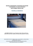
3.7
Color Enhancement Function
(1) Function
The color enhancement function consists of 3 PWBs, each of which has
the following functions:
(a) IMAGE MEMORY
Xl> Persistence function (Normal-V, ANGIO)
x2> ANGIO DR
x3> ANGIO DISPLAY TYPE
(b) ADC/LB/CAL
The new functions are controlled by the PC DSC (CFM DSC).
<l> V-FILTER
(control of low-velocity blanking)
<2> P-FILTER (control of high-power blanking)
<3> Control of the dynamic range of the power value
(coupled with ANGIO DR, COLOR RESOLUTION)
(c) PC DSC (CFM DSC)
cl> 3D PERSPECTIVE
<2> COLOR CAPTURE
x3> COLOR RESOLUTION
<4> ANGIO DISPLAY LEVEL
3-52
SSA-340A Color Enhancement Block Diagram
RGB-CNV
ADC/LB/CAL
P and V FILTER,
P-DR Control
l
Input buffer
_+ 0 Lateral filter
.
)
Blank
processing
section
4
I
-..-+
Color
resolution
+
output
buffer
0 Capture
;‘*
3D
I
1
I
l
l
w
l
(;?I
*
1 1
4
:
P-FILTER
V-FILTER
P-Dynamic Range
w”
IL_______,
1
l
l
l
Image Memory
IMAGE MEMORY
1
2
Angio DR
Angio
persistence
V-New
persistence
.
Angio
display
,
1
V-Old
persistence
type
)
I
I
MUX
A
t
/“\
I
*
1
)HFHxh
l
h-lM
No. 2D730-133E
4.
SOFTWARE
4.1
4.1.1
Overview
Interfacing with the hardware
(1)
Noise elimination
The system is designed so that the CPU bus is made available only
when the CPU accesses a terminal to prevent image data from being
affected by noise (12 MHz) on the bus. Figure 4.1-Z shows the CPU
Figure 4.1-l shows how the CPU bus gate
bus gating arrangement.
allows the CPU to access a terminal.
The system, in the same manner as for the EX series, opens the
gate, allows the CPU to access several I/O units, then closes the
gate, for more efficient processing.
The CPU accesses
the terminals.
The gate is closed.
Figure 4.1-l
(2)
CPU bus gate operation
Logical system configuration
Figure 4.1-3 shows the logical configuration (i.e., the software
and hardware control paths) of the system. As seen from this
figure, the software controls almost all of the units (boards).
The system has about 500 hardware ports. For efficiency, software
controls the minimum number of hardware ports each time. Hardware
outputs are used for presetting the probes, scanning, normal
processing, gain processing, independent I/O processing, and other
special processes.
4-l
No. 2D730-133E
CPU PWB
Gate
Internal bus
External bus
Terminal board
I/O
port1
communication
RAM
Figure 4.1-Z
K=
Operation of the CPU bus gate
4-2
No. 2D730-133E
4.1.2
Organization
of software
(1) Relationships
between tasks
Figure 4.1-4 shows the relationships between tasks. Processing is
Therefore, the ISR (interrupt
always performed via interrupts.
service routine) is provided at the beginning of the flow of
processing to branch processing to each task. The, term "task"
refers to a related series of work procedures.
This
An OS (operating system) is used to control all software.
system uses MONEX (Monitor for EX) as the operating system.
ISR includes "SW', "probe", "VCR TALLY", 'OF", "FI", "RTC", "KG",
'black/white DSC hole pixel calculation completion", "color DSC
hole pixel calculation completion", and "DSC error" ISRs.
Initialization
pressed.
is performed at power ON and when the RESET SW is
"SW processing" is activated via "panel processing" from "SW ISR"
when the SW on the panel or the pop-up menu is pressed, from
'probe ISR" when a probe is connected/disconnected, or from "VCR
"SW processing'
TALLY ISR" when the status of the VCR is changed.
calls subordinate tasks using SW code and other information.
The image CONT is used for analysis of image data, and the
measurement CONT is used for analysis of measurement data in
detail. In other cases as well, processes up to the broad
classification of the SW code are performed by "SW processing",
and detailed analysis of the SW code is performed by subordinate
tasks.
Subordinate tasks of SW processing include "NEW PATIENT, CONDITION
PRESET", "image CONT", "measurement CONT", "fixed character",
"ID " , 'arbitrary character", "timer adjustment", "body mark",
'preset menu", 'register processing", "patch function", "RS232C
BREAK", "RS232C measurement data setting", "RS232C data output",
and "test" tasks.
When a measurement-related SW is input, 'measurement CONT' is
activated from "SW processing", detailed analysis of the SW code
The
is performed, and subordinate tasks are activated.
subordinate tasks include "distance measurement', "area (trace)",
"area (ellipse)", "area (rectangular)", "histogram", "velocity
trace", "velocity histogram", "color velocity measurement',
"profile", "heart volume trace (MANUAL)", "calculator function",
and "report". Application measurement functions are provided in
the *'measurement CONT" to permit various types of application
Application measurements provide LV measurements,
measurements.
MV measurements, AoV measurements, fetal measurements, Doppler
measurements, and user-defined measurements that support the
user's requirements in as flexible a manner as possible.
4-4
;4=
No. 2D730-133E
When an image-related SW is input, the "image CONT" is activated
For time-consuming marker display, this
from "SW processing".
The "image
system handles "marker" as a task to abort processing.
CONT" contains each type of function: "image CONT main", "image
memory main", "hardware control", and "auto data display".
"OF ISR" has the "OF" task, "FI ISR" has the "FI" task, "RTC ISR"
has the "RTC" task, "ECG ISR" has the "ECG" task, and "black/white
DSC hole pixel calculation completion ISR" and "color DSC hole
pixel calculation completion ISR" have the "DSC" task, and "DSC
error ISR" has the "ERROR" task.
"Exception processing" is provided as processing when a software
"Common functions" and "Common functions for
malfunction occurs.
measurements" are provided as common functions shared with
"Common table" and "T&R delay data table" are provided
software.
to support additional probes by simply making a minor change of
the table. Separate tables are provided for measurement-related
data, auto annotation, and body mark data on which demands
specific to the user are made so that service personnel can make
additions or modifications.
4-5
g4-_
No. 2D730-133E*F
4.2
Error Codes and Messages
The host CPU detects errors and outputs error codes and messages.
If an error code appears on the monitor, find it in the following list:
(1) Error codes
4:
Error code
Description
5200
The local CPU of the monochrome DSC generated an interrupt but
the host CPU did not receive it.
5201
No FI interrupt from the PANEL I/F section on the CPU PWB in
calculation of TR delay time.
5202
The local CPU of the ECG/NONFADE board generated an interrupt
but the host CPU did not receive it.
5204
The host CPU failed to access the C-RAM in the monochrome DSC.
5205
The host CPU failed to access the C-RAM in the color DSC.
5206
Undefined probe ID detected by the host CPU.
5208
The local CPU of the COLOR DSC generated an interrupt but the
host CPU did not receive it.
5209
The host CPU failed to access the C-RAM in the FFT/CONT/AUDIO
board.
5215
The host CPU received no OF interrupt from the RPG section on
RPG/TRCONT board after sending OF RESET information to the RPG
section.
5218
The host CPU received no OF interrupt from the RPG section
before sending TR OFF information to the T/R CONT section on
the RPG/TRCONT PWB in freeze on mode.
5219
The host CPU received no OF interrupt from the RPG section on
the RPG/TRCONT PWB before erasing frame memory.
5221
OF signal is not generated within 3 seconds after MECHA OF
signal is switched to RPG OF signal.
5222
Control of the MECHA-CONT PWB is not set to OFF within one
second after the host CPU outputs OFF to the MECHA CONT control
I/O.
(Endless loop)
5223
The host CPU received no OF interrupt from the RPG section on
the RPG/TRCONT PWB when it expected the interrupt.
5224
The host CPU received no OF interrupt (or ECG OF interrupt
during ECG SYNC) from the RPG section on the RPG/TRCONT PWB
when the freeze switch was pressed during recording in B-LOOP
image memory mode.
5225
The host CPU received no OF interrupt from the RPG section on
the RPG/TRCONT while re-recording images in image memory.
4-7
No. 2D730-133E*F
Description
Error code
5226
The host CPU received no OF interrupt from the RPG section on
the RPG/TRCONT when the image memory is to be erased.
5450
The host CPU failed to access the C-RAM on the ECGINONFADE
board.
(2) Error messages
Error message
Description
EEPROM CHECK ERROR
Writing in EEPROM for check does not end within 2.5
seconds.
EEPROM INIT ERROR
EEPROM is not ready to be written
EEPROM WRITE ERROR
Writing in EEPROM does not end within 2.5 seconds
after write operation completed.
TR ERROR . . . . .
The high voltage falls below a preset limit due to a
fault in the TR circuitry.
MECHA PROBE ERROR
There is an abnormality in the annular array sector
transducer, connections from the MECHA-CONT PWB to
the annular array sector transducer, or the MECHACONT PWB.
4-a
(at power on).
No. 2D730-133E*J
5.
POWER SUPPLY UNIT
This unit supplies power to the main unit and external devices.
are two types of power units for 100 VAC and for 200 VAC.
There
(I) Ratings of line voltage
o 100-VAC unit
Input voltage:
100 VAC -10X to 127 VAC +10X
o 200-VAC unit
Input voltage:
220 VAC -10X to 240 VAC +10X
Input power frequency:
50 Hz or 60 Hz
(2) Functional description
The AC input is connected to the power unit by a cord and goes via
circuit breakers and a line filter to terminals 1 and 2 of the
terminal board (connected to a switch). Terminals 3 and 4 of the
terminal board are connected to the isolation transformer via a
filter.
The AC output is output from the secondary of the isolation
transformer to AUX OUT (POlOJN, POllJN, POlZJN).
POlOJN is used for the color observation monitor, and POllJN is
connected to AC OUTLET on front panel 2 and P012JN is connected to AC
OUTLET on front panel 1.
Another AC output is output from transformer to the DC power supply.
Eleven regulated voltages of +5 V, -5 V, -5.2 V, i-15 V, -15 V, i-12 V,
t10 V, VL, VH, VP, and VN are output from the stable DC power supply
and direct current and voltage are supplied to each unit through the
output filter.
(3) Abnormality detection
The following abnormality detection functions are provided in the
power supply unit for direct stable power supply outputs. When one
of the direct outputs is abnormal, all outputs of the direct stable‘
power supply are shut down.
(a) Overcurrent detection
(b) Overvoltage detection
When the FAN is stopped, abnormal temperature rise is detected and
all outputs of the direct stable power supply are shut down.
5-1
No. 2D730-133E
THIS PAGE IS LEFT
5-1A
BLANK INTENTIONALLY
No. 2D730-133E
7.
ADJUSTMENTS
Adjusting the anti-RF1
(anti radio frequency interference)
circuit.
(1) Principle
This circuit comprises of 2 series of notch filters which include
parallel-connected Ls and Cs. By changing the values of Ls and Cs,
the elimination frequency (fr) can be set. Attenuation with fr is
-50 dB to -60 dB.
Figure 7-1
-7:
-
_
The noise-elimination frequency (fr) can be set by changing the
combinations of the 3 Ls and 2 Cs, and by changing the value of Cs
For the combinations of the Ls and Cs
using the trimmer capacitor.
specifying the adjustment range for fr, refer to table 7-1. (The
settings indicated with No. 1 in the table are used at the time of
shipment from the factory.)
7-l
=7----_
No. 2D730-133E
(2) Countermeasures
against RF1
(a> Checking for RF1
Hold the probe and check whether or not noise, which is
apparently caused by external radio frequency, is displayed on
the CRT when the gain is turned up. When noise is observed,
follow the steps below:
(b)
Investigating
radio frequency interference
Investigate radio frequency interference using a field-strength
(If investigation shows any transmitter
meter, radio, etc.
station near the site, the interfering radio frequency can be
guessed.)
cc> Adjusting
the notch filters
a. Pull out the DVAF/RECEIVER
PWB using the extension PWB.
b. Set SWl-1 and SWl-4 to OFF.
c. Refer to table 7-1 to select the combination of the SWs so
that the interfering radio frequency is placed at the center
of the frequency range for noise elimination.
d. Turn the power ON and turn up the gain until RF1 noise can be
observed easily. Use an insulated screwdriver to adjust VCR1
and VCR2 so that the RF noise is minimized.
e. Observe an abdominal image and check that there is no
(When the
abnormality such as significant decrease in S/N.
filter is adjusted to 1.5 MHz to 2.5 MHz, the signal level is
If interfering radio
This is not a malfunction.
decreased.
frequency is more than 2 MHz, the notch filter will cause the
For this reason,
signal level to be decreased tremendously.
it is recommended that another type of countermeasure (line
filter, for example) be taken.
;7---_
7-2
No. 2D730-133E
Table 7-l
No.
frequencies
(MHz)
1
____
to
2
3
4
5
6
7
8
9
10
11
12
0.48
0.53
0.6
0.7
1.5
1.9
4.9
5.3
5.5
6.2
6.5
to 0.54
to 0.65
to 0.8
to 1.9
to 2.1
to 5.1
to 5.4
to
7
to 7.4
to
15
to
16
Note:
----
SW2
SW1
Range for removable
1
1
; 2
I
I
13
'4
ON 1 OFF ; OFF 1 ON
OFF
OFF
OFF
OFF
OFF
OFF
OFF
OFF
OFF
OFF
OFF
1 ON
f OFF
1 OFF
; OFF
; OFF
; OFF
; ON
; OFF
I OFF
; OFF
' OFF
I ON
; OFF
1 OFF
; OFF
; OFF
; OFF
f ON
; OFF
; OFF
1 OFF
; OFF
! OFF
i OFF
1 OFF
f OFF
; OFF
; OFF
1 OFF
; OFF
; OFF
1 OFF
1 OFF
SW3
0
3
2
3
2
5
6
E
9
F
8
E
The combinations of SW2 and SW3 setting which are not
listed can also be used.
7-3
*
No. 2D730-133E
8.
8.1
PATCH MENU OPERATION
Applicable
Equipment
SSA-340A
8.2
Starting
Important notice:
This starting procedure is for authorized personnel only (for software
This <procedure must not be disclosed to the user.
protection).
~SETTING] menu,
-.I
&
On the full-keyboard
J
Also start with the -1
menu, by pressing
/KZij.
The PATCH MENU is displayed.
PATCH MENU
HIT
(I
-
4)
KEY
1. MEMORY R/W SCDUMP
To write data (e.g., a test pattern) to a desired
memory port
2. COORDINATE CHECK (X, Y)
To display a point at a desired set of coordinates in
graphic memory for coordinate checking
3. IMAGE-CONT EXTERNAL VALUE SET
Turns off control from the IMAGE CONT and uses fixed
values
4. ADDRESS & DATA VALUE SAVE
To write data to up to 20 ports
(3) To select a patch item from the PATCH menu, press the number key on
See 8.3 to 8.6 for descriptions of patch items 1
the full-keyboard.
to 4.
(4) Quit with the ISERVICE] menu, by pressing
Notes:
El.
1. Data set in the PATCH menu cannot be cleared with a
CONDITION PRESET operation.
2. Data set in the PATCH menu can be cleared by a NEW
PATIENT operation.
8-l
No.
8.3
2D730-133E
Memory R/W & Dump
(1) When "1" is entered in the PATCH menu, the following menu is
displayed:
HIT
(I
-
4)
KEY
1. I/O READ
2. I/O WRITE
3. HEX DUMP
4. LISTOUT (HEX & ASCII)
(2) To select a desired item from this menu, enter the number
for item 1, or "W" for item 2) on the full-keyboard.
(or "R"
(3) Functions of the other keys with this menu
(a) [Sl key
When this key is pressed, this menu ends and the PATCH menu (see
8.2 (2)) is redisplayed.
(b) [+I key
When this key is pressed, the address is increased by two.
(c) [+I key
When this key is pressed, the address is decreased by two.
(d) [?I key
When this key is pressed, the address is increased by 256.
(e) 141 key
When this key is pressed, the address is decreased by 256.
8-2
No. 2D730-133E
8.4
Coordinate Check (X,Y)
(1) Data to be entered in this menu
(a) X = X coordinate
(b) Y = Y coordinate
(c) X-DOT = Number of dots in the X direction
(d) Y-DOT = Number of dots in the Y direction
Data items (a), (b), (c), and (d) change in that order each time the
[CR] key is pressed.
(2) Press the [S] key to terminate operations for this menu and to
redisplay the PATCH menu (see 8.2 (2)).
8.5
Image Cont External Value Set
(1) When "3" is entered in the PATCH menu, the follow-menu is displayed:
DATA
ADDRESS
1.
(
>
(
>
2.
(
1
(
1
3.
(
>
(
1
4.
(
)
(
>
5.
(
>
(
>
6.
(
>
(
1
7.
(
)
(
>
8.
(
)
(
>
9.
(
)
(
>
10.
(
)
(
1
8-3
No. 2D730-133E
(2) Functions of the other keys in this menu
(a) [ENTER] key
Press this key after entering an address and data.
(b)
[DELI key
Press this key to delete all addresses and data.
(c) [SPACE] key
Press this key to delete one address and data value.
(d)
[‘f’l key
Press this key to move the cursor up (from 10 to 1).
(e)
i-11 key
Press this key to move the cursor down (from 1 to 10).
(3) PATCH MENU display by KEY IN "S".
(2).)
(Return to the status in 8.2
(4) Data output timing
o IMAGE CONT EXTERNAL VALUE SET is selected in the PATCH menu.
Data is output before hardware-controlling
performed.
I/O processing is
("(PM3)" is displayed during execution of the program.)
(5) Turn off the PATCH menu.
Note:
The PATCH program starts.
To terminate processing, call up the PATCH menu again.
8-4
No. 2D730-133E
8.6
Address & Data Value Save
(1) When "4" is entered in the PATCH menu, the following menu is
displayed:
DATA
ADDRESS
1.
(
>
(
>
2.
(
1
(
>
3.
(
>
(
>
4.
(
1
(
1
..
..
~
17.
(
>
(
1
18.
(
>
(
>
19 .
(
1
(
1
20.
(
>
(
>
(2) Functions of the other keys in this menu
(a) [ENTER] key
Press this key after entering an address and data.
(b) [DEL] key
Press this key to delete all addresses and data.
(c) [SPACE] key
Press this key to delete one address and data value.
00
[‘h key
Press this key to move the cursor up (from 10 to 1).
Press this key to move the cursor down (from 1 to 10).
(3) Display the PATCH MENU by KEY IN "S".
(2).)
Note:
(Return to the status in 8.2
The set data is saved in EEPROM and preserved, even after
the power is turned OFF, until the EEPROM is initialized by
using DIP SW3.
8-5
No. 20730-133E
(4) Data output timing
o ADDRESS b DATA VALUE SAVE is selected in the PATCH menu.
Data is output after hardware-controlling I/O processing is
performed ("(PM4)" is displayed during execution of the program).
(5) Turn off the PATCH menu.
I Note:
The PATCH program starts.
To terminate processing, call up the PATCH menu again.
S-6
I
TOSHIBA
TOSHIBA
CQRPORATION
1385,SHIMOIStilGAMI,OTAWARA-SHI,TOCHIGI-KEN
324-8550,JAPAN