1
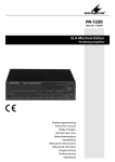
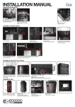
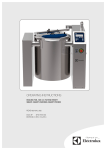
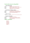
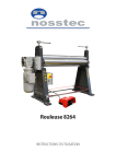
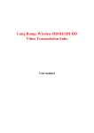
n
e i by
d
Maeden
Sw
Thawing cabinet
Tina 1200RM
Service manual
DOC.NO EDITION 2
STO 4764-02
2015.10
Contents
General instructions
Component placement Tina1200RM
Replacing the air heating element Replacing the fan
Replacing the Powered ball valve
Replacing the PCB
Replacing the speed control
Control panel
Technincal data
Functional specification Tina 1200RM
Parameter setup
Calibration Loading default values
Error codes and Truble shooting
Page
3
4
5
5
6
6
7
8
8
9
10-15
16-17
18
19
Producer: SteelTech i Alingsås AB. Lärkvägen 4. SE-441 40 Alingsås. Sweden
Phone: +46 322 668930 . Fax: +46 322 10870
E-mail: [email protected] .www steeltech.se
2
General instructions
If the instructions in this and other documentation for
the equipment are not followed, it could endanger
safety and void the supplier’s guarantee and liability for the product.
· Read the instructions in this document carefully,
since they contain important safety information
about installation, operating reliability, use and
maintenance of the product. Keep these documents so that they are available to relevant users.
· Installation and testing must be carried out by
technicians who are trained for such work, and in
accordance with the manufacturer’s instructions.
· The product must be installed and connected to
the necessary services in accordance with the relevant standards and directives.
· All servicing, maintenance and repairs must be
carried out by technicians who are trained for
such work. Use only original spare parts. See the
Spare parts catalogue*.
· This product may only be operated and maintained by trained personnel (operators).
* Not supplied. May be ordered from the manufacturer or
manufacturer’s representative.
Warning! Electricity!
Warning sign indicates the thawing cabinet’s electrical enclosure. The door of the electrical enclosure
and other cover panels may only be opened by
technicians who are trained for such work.
Warning!
· The outside of the thawing cabinet should not be
rinsed.
· If water comes into contact with live components
it could be fatal. Always take care when cleaning,
especially when close to electrical components.
· Use a damp cloth for cleaning.
Warning!
Note that the interior surfaces of the thawing cabinet
can become hot during the cleaning program and
cause burns if touched.
Also take care when the cabinet door is opened.
Heat escapes and can cause personal injury.
CE directives
Technical data
Tina 1200RM is manufactured in accordance with the
directives, LVD2006/95/EG, EMC 2004/108/EG and
is CE marked.
Safety instructions
· Switch off the power before attempting to rectify
faults or operating problems with the thawing
cabinet.
- Set the selector switch in the 0 position. (See
Operating Instructions)
– Switch off the Main circuit breaker (NOT found
on the thawing cabinet).
Rating plate
The product number for the thawing cabinet can be
found on the rating plate, which is placed on the
bottom left-hand side of the thawing cabinet and
on the rear of the electrical enclosure, as well as on
the EU declaration of conformity supplied with the
machine on delivery.
Noise level: <70dB
Enclosure class: IP44
Note!
In case of welding on the Thawing cabinet,
disconnect the electronic device by using the
connection blocks marked (X10- X16) on the PCB
(see the picture). See Fig. 1
Be cautious when re-connecting the electronic device
after welding job and control all connections before
re-starting the Tina thawing cabinet.
Fig. 1
3
Component placement Tina 1200 RM (Fig. 2)
25
1
24
2
23
3
22
4
21
5
20
6
19
7
18
8
17
9
16
15
14
13
10
12
11
Fig. 2
1.
Overheating protection
14. Support contactor
2.Fan
15. Temperature sensor
3.
Control PCB
16. Powered ball valve
4.
Key switch
17. Glass Level gauge
5.Fuse
18. Tube heater
6.
19. Air heating element
Speed control
7.Contactor
20.Evaporator
8.
21. Radiator coupling
Terminal block
9.Capacitor
22. Magnet valve
10. Food probe
23. Back flow priventor
11. Transformer, electronic
24. Solenoid valve
12. Transformer, 440V-230V
25. Expansion valve
13. Automatic fuse
4
Replacing the air heating element (Fig. 3)
Fig. 3
Loosen the electrical cabinet door and place to the side of the opening. Disconnect the element cables at
connection X3, position 4 and 6. (cable nr 28 and 29) Loosen the cable from the harness. Open the cabinet
door and lift out the bottom guide and air distributor plate. Fold down the cover. Unscrew the air element
from its mounting and pull it down through the top. Fit the new air element in the reverse order.
Fig. 4
Replacing the fan (Fig.4)
Loosen the electrical cabinet door and place to the side of the opening. Disconnect the fan cables at connection X3, position 7 to 14. Loosen the cables from the harness. Open the cabinet door and lift out the
bottom guide and air distributor plate. Fold down the cover. Unscrew and move the cavity probe and overheating protection fitted to the underside of the fan cover to one side. Remove the fan cover. Dismantle the
complete fan enclosure by unscrewing the 6 screws in the top and then carefully lift it out, without damaging
the cables. (This should be done with the help of a colleague due to the weight of the fan enclosure.) Replace the faulty fan by removing the screws on the top of the fan enclosure. Replace seal if damaged. Assemble in the reverse order.
5
Function description of the Powered ball valve (drain valve)
The powered ball valve opens and closes automatically every time the thawing cabinet starts or using the
desinfection/cleaning program. The process takes approximately 2.5 minutes
Ball valve
Drive unit
Fig. 5
Replacement of the Powered ball valve (drain valve) Fig. 5
The Powered ball valve is delivered always complete with both drive unit and ball valve. In case of function
failure delime first, if the function disorder still remains replace the drive unite first (marked in the electrical
wiring diagram as M4).
- Dismantle the electrical connection of the valve.
- Separate the drive unit and the ball valve by using the screw in the side of the valve.
- Replace the drive unit.
Replacing the PCB board:
After replacing the PCB board be sure that right size Tina thowing cabinet is choosen.
See Calibration page 13.
Change the battery: Lift the back stop bar over the battery and changeto:
Type: CR 2032
3V
Minus pole twards the PCB.
6
Voltmeter
Fig. 6
Adjusting screw
Replacing the speed controll unit (U1) Fig. 6
. In case of replacing the speed control unit itis neccessary to adjust the fan speed.
. Connect a Voltmeter to connection marked FAN Points 8 and 10
. Adjust the voltage by using the adjustment screw in connection marked Speed adj. poit 19 (800rpm) as in
the table below.
. Measure the fan speed if there are instrument avalable as shown in the table below.
Low speed: 750-850 rpm
High speed: 1300-1400 rpm
ModelConnection Voltage
Adjusting Voltage
124V 400 3 ~50
Tina1200RM 400/440 3 ~60
140V
Basic adjustment of the radiator coupling
Loosen the prtecting cap on the adjusting screw. Close the adjusting valve completely.Open the valve extremely little. The flow have to be 1 l /min. Re-assamble the protecting cap.
7
Control panel
aON/OFF
b Select/ (HACCP) printing
c Increase/decrease value
dDisplay
eConfirm
f Start/Stop of process
g Standard (Pre-set) thawing programs
h Manual thawing program
j Bactericidal/cleaning mode
k Refrigeration mode
T Thawing/deliming key
g
h
j
k
Standard (Pre-set)
thawing programs
Manual thawing program Cleaning/Bactericidal
mode
Refrigeration
mode
Fig. 7
Technical data
Model
Volume Max. weight of
Capacity
Door
Voltage ltrs defrosting food baskets/containers hung
Loading Cooling
Fuse
kW kcapacity kW A
Weight kgs
net
gross
Note
right 400 3 ~50
10
Tina1200RM 1200
200 kg
13 GN 2/1
left
4
1,5
295
310 right 440 3 ~60
10
left
8
Functional specification Tina 1200RM
Thawing
1.
Start up
Push the Start/Stop (f)
to start the thawing process. (See even the Hand book)
Fan no.1 starts.
Steam generator is emptied and refilled.
The probe detects that the frozen products have a temperature below set target temperature (0-1°C).
The thawing process starts.
• Fan no.2 starts.
• The frozen products lower the temperature in the cabinet.
•
•
•
•
2.Heating up phase
• A
s the cabinet temperature is decreased below 7°C the steam generator starts.
• After 5 minutes the extra heating element is also energized.
• As the probe has been detecting a temperature below set target temperature for a period of 10
minutes the cabinet temperature is increased to 15°C by the steam generator.
• After 5 minutes the heating element is energized.
• The cabinet then maintains 15°C mainly by using the steam generator. (The heating element operates
with a 5 min. delay)
• When the frozen products reaches target temperature minus 3°C, the cabinet temperature is limited to
7°C.
• If the cabinet temperature stays over 7 or 15°C for more than 5minutes, the refrigiration system will
lower the cabinet temperature.
• The product surface temperature then increases to set target temperature (0-1°C).
3.Temperature equalization phase
• A
s the probe detects set target temperature the steam generator, the heating element and fan no.2 is
shut of.
• The products surface temperature then lowers, as the product core is still cold. As the probe detects a
temperature below the target temperature the heating up phase re-starts from step 2.
• If the probe has not detected a temperature below set target temperature for 5 minutes the cooling
system starts and lowers the cabinet temperature to 2°C.
4.
Cold storage
• S
tep 2 and 3 is automatically repeated several times until the probe detects that the surface
temperature has stabilized on the target temperature.
• The cabinet then keeps a temperature of 2°C.
• Remaining ice crystals in the core of the product is now slowly thawed without affecting the surface
temperature. (Temp.difference between core and surface of product <2°C)
• The steam generator is energized for 4 minutes every 40minutes, this to prevent dry out of the food.
• The heating element is energized for 3 minutes every 30min, this to reduce ice on the evaporator.
• As this heating element is on the cooling system and the steam generator is automatically switched off.
5. Thawing ready.
Cleaning program
• Push button (j),
•
•
•
•
and then the Start/Stop (f)
to start the cleaning process
Steam generator is emptied and refilled.
The fans starts.
The steam generator and the heating element heat the cabinet to 80°C and maintain it for 5 minutes.
Steam generator, element and fans are then shut of and the cleaning phase is done.
9
PARAMETER SET-UP
1.
OFF state
1.2 Cycle parameters program:
The following text appears in the display:
OFF
1.3 Preset program:
Alternatives from Off state:
1.1
Ready state:
Push ON/OFF (a)
This function is reserved for the factory settings
only.
This function is reserved for the factory settings
only.
.
1.2 cycle parameters program:
1.3 Preset program:
1.4 Initiate internal/customer parameter:
Push Start/Stop (f)
in 5 seconds.
1.5 Calibration program:
Push Scroll (g) button
and Scroll (g) button . in 5 seconds.
1.6 Loading default values of cycle parameters:
Push Scroll (g) button
in 10 seconds.
1.7 Print events memory:
Push Select (b) button
in.
1.8 Clear events memory:
Push Scroll (g) button
in 10 seconds.
NOTE:The Tina thawing cabinet will return back
to ”OFF STATE” if no buttom pushes in more than
5 minutes.
NOTE: It is possible to regret any buttom pushing
by pushing the Start/Stop (f)
buttom.
10
1.4 Initiate internal/customer parameter:
1.4.1 Choice of language
A buzzer confirms the changes.
Push Start/Stop (f) .
The following text appears in the display:
NOTE! The factory setting is English.
Available languages are:
Deutsch (German)
English
Español (Spanish)
Française (French)
Italiano (Italian)
Svenska (Swedish)
SAVE CHANGES?
YES
Choose alternative by using scroll (g) button
or .
Push Enter (e)
button to confirm the selection.
The following text appears in the display:
The following text appears in the display:
OFF
SAVING CHANGES
SAVING
Push Start/Stop (f)
in 5 seconds
The following text appears in the display:
OFF
SELECT LANGUAGE
ENGLISH
To choose language use scroll (g) button
or
Push Enter (e)
button to confirm the selection.
The following text appears in the display:
.
SELECT LANGUAGE
Español
The following text appears in the display:
CUSTOMER PARAMETER
ENTER PASSWORD
11
1.4.2 Initiate internal/customer parameter:
The following text appears in the display:
If YES is chosen following text appears in the
display:
OFF
Push Start/Stop (f)
in 5 seconds.
The following text appears in the display:
SELECT LANGUAGE
ENGLISH
Push Enter (e)
button to confirm the selection.
The following text appears in the display:
CUSTOMER PARAMETER
ENTER PASSWORD
ENTER NEW PASSWORD
Enter the new password by pushing buttons (g),
(h), (j) and (k) in chosen order.
Push Enter (e)
button to confirm the selection.
The following text appears in the display:
CONFIRM NEW PASSWORD?
Enter the new password by pushing buttons (g),
(h), (j) and (k) in chosen order.
Push Enter (e)
button to confirm the selection.
The following text appears in the display:
To write the password push buttons (g), (h), (j)
in a row
,
,
.
Push Enter (e)
button to confirm the selection.
The following text appears in the display:
The password changes.
The following text appears in the display:
CUSTOMER PARAMETER
INTERNAL PARAMETER
CHANGE PASSWORD?
NO
Push scroll (g)
or
to choose alternatives
NO( default) or YES:
Push Enter (e)
button to confirm the selection.
If NO is chosen the following text will appears
in the display:
PASSWORD CHANGED
Push scroll (g)
or
to choose alternatives:
1.4.2.1:
INTERNAL PARAMETER
1.4.2.2:
CUSTOMER PROGRAM.
CUSTOMER PARAMETER
INTERNAL PARAMETER
12
1.4.2.1:
INTERNAL PARAMETER
To write the password push buttons (g), (h), (j)
The following text appears in the display:
in a row
,
Push Enter (e)
,
.
to confirm the selection.
The following text appears in the display:
CUSTOMER PARAMETER
INTERNAL PARAMETER
Push Enter (e)
to confirm the selection.
The following text appears in the display:
SET DATE FORMATE
YY-MM-DD
Push scroll (g)
or
to choose alternatives
Push Enter (e)
to confirm the selection.
The following text appears in the display:
SET TIME FORMATE
24:00
Push scroll (g)
Push Enter (e)
or
to choose alternatives.
to confirm the selection.
The following text appears in the display:
SET CURRENT YEAR
2015
Push scroll (g)
or
to choose alternatives
Push Enter (e)
to confirm the selection.
The following text appears in the display:
SET CURRENT MONTH
XX
Push scroll (g)
or
to choose alternatives
Push Enter (e)
to confirm the selection.
The following text appears in the display:
Push scroll (g)
Push Enter (e)
SET CURRENT DAY
XX
SET CURRENT TIME
hh:mm
Push select (b) button
to scroll between
hour(hh) and minutes(mm)the selection.
Push scroll (g)
or
to increase or decrease
the value.
Push Enter (e)
to confirm the selection.
The following text appears in the display:
TEMPERATURE SCALE
°F
Push scroll (g)
or
to choose between °F for
”Farenheit” or °C for ”Centigrade” scales.
or
to choose alternatives
to confirm the selection.
13
The following text appears in the display:
PRESS BUTTON BEEP
YES
Push scroll (g)
or
to choose alternatives YES
(default for have a beep qhen pushing buttons)
or NO(no beep)
Push Enter (e)
to confirm the selection.
The following text appears in the display:
PC CONNECTION
YES
Push Enter (e)
to confirm the selection.
The following text appears in the display:
EVENTS INTERVAL
10 MIN
Push scroll (g)
or
to choose between 02
to 59 minutes.
Push Enter (e)
to confirm the selection.
The following text appears in the display:
PRINT DURING CYCLE
YES
Push scroll (g)
or
to choose alternatives
NO( default) or YES.
The following text appears in the display:
The following text appears in the display:
MULTI NETWORK 10
01
Push Enter (e)
to confirm the selection.
The following text appears in the display:
PRINTER CONNECTION
CUSTOM FT190S
Push scroll (g)
or
to choose alternatives:
1.4.2.1:
INTERNAL PARAMETER
1.4.2.2:
CUSTOMER PROGRAM.
Push scroll (g)
or
to choose alternatives
NO or CUSTOM FT190S (default).
Push Enter (e)
to confirm the selection.
The following text appears in the display:
PRINTER BAUDRATE
1200/2400/4800/9600
Push scroll (g)
Push Enter (e)
CUSTOMER PARAMETER
INTERNAL PARAMETER
or
to choose alternatives.
to confirm the selection.
14
14.2.2:
CUSTOMER PROGRAM
Push Enter (e)
to confirm the selection.
The following text appears in the display:
CUSTOMER PROGRAM
XX
xx.xx°F
The following text appears in the display:
Push Enter (e)
Push Enter (e)
to confirm the selection.
The following text appears in the display:
NAME
Push scroll (g)
or
to choose alternative
letters.
Push select (b)
to scroll between positions.
Push Enter (e)
to confirm the selection.
The following text appears in the display:
NAME
SET T
xx.xx°F
Push scroll (g)
or
to set the temerature.
Push Enter (e)
to confirm the selection.
The following text appears in the display:
CUSTOMER PROGRAM
NAME
xx.xx°F
Push Enter (e)
to confirm the selection.
The following text appears in the display:
CUSTOMER PARAMETER
CUSTOMER PROGRAM
Push Start/Stop (f)
ges.
anytime to save the chan-
15
SAVE CHANGES?
YES
to confirm the selection.
1.5 Calibration program:
There are possibilities to calibrate Tina’s temperature probes in case of replacement of probes
or failure in the temperature scales. To make
sure that the calibration is correct use always
a calibrated thermometer to compare with the
values fore Tina probes.
The following text appears in the display:
OFF
Push Scroll (g) buttons
and
simultaneously
in 5 seconds.
The following text appears in the display:
CALIBRATION
ENTER PASSWORD
the Service personal will be able to see the users
password.
The following text appears in the display:
BRIGHTNESS
XX%
Push scroll (g)
or
to choose alternatives
25, 50,75 or 100%:
Push Enter (e)
to confirm the selection.
The following text appears in the display:
CALIBRATION
FOOD PROBE
Push Enter (e)
to confirm the selection.
The following text appears in the display:
To write the password push buttons (g), (h), (j)
in a row
,
,
Push Enter (e)
to confirm the selection.
The following text appears in the display:
CHOOSE TINA MODEL
TINA 180
Push scroll (g)
or
to choose alternatives
TINA 180 (default) or TINA 1200.
Push Enter (e)
to confirm the selection.
The following text appears in the display:
FOOD PROBE
-X.X
Push scroll (g)
or
to set the temerature
(possible to adjust ±3.6°F(±2°C).
Push Enter (e)
to confirm the selection.
The following text appears in the display:
Push scroll (g)
letters.
Push select (b)
SHOW PASSWORD
NO
Push scroll (g)
or
to choose alternatives
NO( default) or YES (If YES alternative is chosen
16
FOOD PROBE
-X.X
or
to choose alternative
to scroll between positions.
The following text appears in the display:
CAVITY PROBE
-X.X
Push Enter (e)
to confirm the selection.
Push scroll (g)
or
to set the temerature
(possible to adjust ±9°F(±5°C).
Push Enter (e)
to confirm the selection.
The following text appears in the display:
CALIBRATION
CAVITY PROBE
Push Enter (e)
to confirm the selection.
A buzzer confirms the changes.
Push Start/Stop (f) .
The following text appears in the display:
SAVE CHANGES?
YES
Choose alternative by using scroll (g) button
or .
Push Enter (e)
to confirm the selection.
The following text appears in the display:
OFF
17
1.6 Loading default values:
There are possibilities to load the default values
incase unsecurity of the values.
NOTE: If calibration of the temperature probes
have been made before reloading the default
program values, the calibration values will be
remained.
The following text appears in the display:
OFF
Push Scroll (g) button
in 10 seconds.
The following text appears in the display:
LOAD CYCLE PARAMETER
YES
Push Enter (e)
to confirm the selection.
The following text appears in the display:
LOAD CYCLE PARAMETER
ENTER PASSWORD
To write the password push buttons (g), (h), (j)
in a row
,
,
The program will reload the default values of
the cycle parameters.
The following text appears in the display:
OFF
1.7
Print events memory:
Push and hold select (b) button
event memory.
1.8
Clear events memory:
Push Scroll (c)
in 10 seconds.
The following text appears in the display:
CLEAR EVENTS MEMORY
PLEASE WAIT
OFF
LOAD CYCLE PARAMETER
PROCEED?
Push Enter (e)
CLEAR EVENTS MEMORY
YES
Use Scroll (c)
or
to choose alternatives
YES or NO.
Push Enter (e)
to confirm the selection.
The following text appears in the display:
The following text appears in the display:
to print the
to confirm the selection.
18
Messages and Error codes
Messages
Cause
Action
STEAMGENERATOR
CHECK SUPPLY
Water canceled
Low water in the steam generator. Check water supply and press START
STEAMGENERATOR
FILLING ERROR
The time for drain and refill of the Check to see if the powered ball
steam generator is too long.
valve is closed.
Check the water supply.
FOOD PROBE
SHORT CIRCUIT
Short circuit in the food probe, Tina Replace and colibrate the food
cotinues working as refrigerator.
probe
FOOD PROBE
BREAK
Short circuit in the food probe, Tina Replace and colibrate the food
cotinues working as refrigerator.
probe
CAVITY PROBE
SHORT CIRCUIT
Short circuit in the cavity probe, Tina Replace and colibrate the food
cotinues working as freezer.
probe
CAVITY PROBE
BREAK
Short circuit in the cavity probe, Tina Replace and colibrate the food
cotinues working as freezer.
probe
FOOD TEMPERATURE
THAWING: TO HIGH
Food temperature to high during Check to see if the food probe is in
the thawing.
the right place.
TEMPERATURE CAVITY
CLEANING: TO HIGH
Cavity temperature to high during Can we do anything?
the cleaning.
TO HIGH
TEMPERATURE
Cavity temperature to high during Open the door.
the thawing/ refrigerator
STEAMGENERATOR
DRAINING ERROR
The time for drain of the steam Check the valve.
generator is too lång.
Current break, the display shows Press ENTER, back to normal process
the time current was back and
how long it lasted. The food temp.
shows the highest temperature.
The key is turned to deliming?
Deliming
FAILURE SUPPLY
16 :25 ZA H BC M
19
iPinium AB
Box 2105, S-612 22 Finspång, Sweden
Tel: +46-122-135 84 Fax: +46-122-444 001
E-post: [email protected]
www.iPinium.se
20