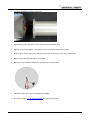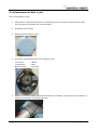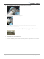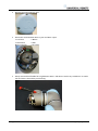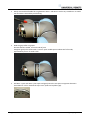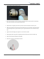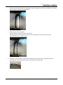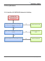
1
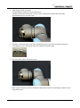
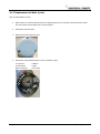
Service Manual Revision UR5_en_3.0.2 Robot: UR5 with CB3-controller valid from robot s/n 2014350001 Contents 1. General information .................................................................................................................................. 4 1.1 Purpose .................................................................................................................................................... 4 1.2 Company details ...................................................................................................................................... 5 1.3 Disclaimer ................................................................................................................................................ 5 2. Preventive Maintenance ........................................................................................................................... 6 2.1 Controller ................................................................................................................................................. 6 2.1.1 Inspection plan, Safety Functions ..................................................................................................... 6 2.1.2 Visual inspection ............................................................................................................................... 6 2.1.3 Cleaning and replacement of filters ................................................................................................. 7 2.2 Robot arm ................................................................................................................................................ 8 2.2.1 Visual inspection ............................................................................................................................... 8 3. Service and Replacement of parts ............................................................................................................. 9 3.1 Robot arm ................................................................................................................................................ 9 3.1.1 Robot arm configuration .................................................................................................................. 9 3.1.2 Brake release .................................................................................................................................. 10 3.1.3 Replacement of base plate ............................................................................................................. 11 3.1.4 Replacement of Base joint .............................................................................................................. 14 3.1.5 Replacement of Shoulder joint ....................................................................................................... 17 3.1.6 Replacement of Elbow joint ........................................................................................................... 19 3.1.6 Replacement of Wrist 1 joint.......................................................................................................... 23 3.1.7 Replacement of Wrist 2 joint.......................................................................................................... 29 3.1.8 Replacement of Wrist 3 joint.......................................................................................................... 33 3.1.9 Replacement of tool flange ............................................................................................................ 37 3.1.10 Torque values ............................................................................................................................... 40 3.1.11 Joint calibration ............................................................................................................................ 41 3.2 Controller ............................................................................................................................................... 47 3.2.1 Handling ESD-sensitive parts .......................................................................................................... 47 3.2.2 Replacement of motherboard ........................................................................................................ 48 3.2.3 Replacement of Safety Control Board ............................................................................................ 51 3.2.4 Replacement of teach pendant ...................................................................................................... 53 3.2.5 Replacement of 48V power supply................................................................................................. 54 All rights reserved 2 Servicemanual_UR5_en_rev3.0.2 3.2.6 Replacement of 12V power supply................................................................................................. 57 3.2.7 Replacement of current distributor................................................................................................ 58 4. Software .................................................................................................................................................. 60 4.1 Update software .................................................................................................................................... 60 4.2 Update joint firmware ........................................................................................................................... 62 4.3 Using Magic files .................................................................................................................................... 65 5. Troubleshooting ...................................................................................................................................... 66 5.1 Error codes............................................................................................................................................. 66 5.2 Error phenomena .................................................................................................................................. 78 5.2.1 ControlBox: NO CONTROLLER displayed in Initializing ................................................................... 78 5.2.2 NO CABLE displayed during power up ............................................................................................ 79 5.2.3 Force limit protective stop ............................................................................................................. 80 5.2.4 Power on failure in Initializing ........................................................................................................ 81 5.2.5 Checklist after a collision ................................................................................................................ 84 5.3 Schematic drawing ................................................................................................................................ 85 6. Spare parts............................................................................................................................................... 86 6.1 Spare part list......................................................................................................................................... 86 6.2 Tool part list ........................................................................................................................................... 87 7. Packing of robot....................................................................................................................................... 88 8. Changelog ................................................................................................................................................ 89 8.1 Changelog .............................................................................................................................................. 89 All rights reserved 3 Servicemanual_UR5_en_rev3.0.2 1. General information 1.1 Purpose The main purpose of this manual is to help the user safely perform service related operations and troubleshooting. Universal Robots industrial robots are designed using high quality components designed for long lifetime. However any improper use of robot can potentially cause failures on the robot. For example, the robot may have been overloaded on an overrun or it may have been dropped on the floor when relocating or have run with a load not recommended by Universal Robots. Any improper use of the robot will invalidate the guarantee. Universal Robots recommends that you do not attempt repair, adjustment or other intervention in the mechanical or electrical systems of the robot unless a problem has arisen. Any unauthorized intervention will invalidate the guarantee. Service related operations and troubleshooting should only be performed by qualified personnel Before performing service related operations, always make sure to stop the robot program and disconnect supply to any potential dangerous tool attached on the robot arm and in the work cell. In the event of a defect, Universal Robots recommends ordering new parts from the Universal Robot distributor from where the robot has been purchased. Alternatively, you can order parts from your nearest distributor, whose details you can obtain from Universal Robots official website at www.universal-robots.com All rights reserved 4 Servicemanual_UR5_en_rev3.0.2 1.2 Company details Universal Robots A/S Energivej 25 DK-5260 Odense Denmark Tel.: +45 89 93 89 89 Fax +45 38 79 89 89 1.3 Disclaimer The information contained herein is the property of Universal Robots A/S and shall not be reproduced in whole or in part without prior written approval of Universal Robots A/S. The information herein is subject to change without notice and should not be construed as a commitment by Universal Robots A/S. This Manual is periodically reviewed and revised. Universal Robots A/S assumes no responsibility for any errors or omissions in this document. Copyright © 2014 by Universal Robots A/S The Universal Robots logo is a registered trademark of Universal Robots A/S. All rights reserved 5 Servicemanual_UR5_en_rev3.0.2 2. Preventive Maintenance 2.1 Controller 2.1.1 Inspection plan, Safety Functions At least once in a year, the correct functioning of all safety functions should be tested. 2.1.2 Visual inspection Disconnect power cable from controller. Open cabinet door. Check connectors are properly inserted on printed circuit boards. Check for any dirt/dust inside of controller. If any dirt/dust is present: » gently use vacuum cleaning for removing particles. All rights reserved 6 Servicemanual_UR5_en_rev3.0.2 2.1.3 Cleaning and replacement of filters Controller box contains two filters, one on each side of controller. Remove filters from controller box and clean them thoroughly using compressed air. » Replace filters if necessary. All rights reserved 7 Servicemanual_UR5_en_rev3.0.2 2.2 Robot arm 2.2.1 Visual inspection Move robot arm to HOME position (if possible). Turn off and disconnect power cable from controller. Inspect cable between controller and robot arm for any damages. Inspect flat rings for wear and damages. » replace flat rings if worn out or damaged. Inspect blue lids on all joints for any cracks or damages. » replace blue lids if cracked or damaged. Inspect that screws for blue lids are in place and properly tightened. » Replace screws, tighten properly if necessary. Correct torque value for screws on blue lids are 0.5Nm If any damages are observed on a robot within the warranty period, contact the distributor from where the robot has been purchased. All rights reserved 8 Servicemanual_UR5_en_rev3.0.2 3. Service and Replacement of parts 3.1 Robot arm 3.1.1 Robot arm configuration J5 Wrist 3 Tool flange J3 Wrist 1 J4 Wrist 2 Lower arm J2 Elbow Upper arm J0 Base J1 Shoulder Baseplate All rights reserved 9 Servicemanual_UR5_en_rev3.0.2 3.1.2 Brake release If required, the brake on a joint can be released without power connected. IMPORTANT NOTICE: Before releasing a brake it is extremely important to dismount any dangerous tooling for avoiding any hazardous situations. If releasing the brake on Base joint, Shoulder joint or Elbow joint, it is important to make proper mechanical support prior to releasing the brake. Always make sure no personnel are located under the arm when releasing the brake. Do not move the joint more than necessary, absolute max. is 180 degrees in order for the robot to find its original physical position. Procedure for releasing the joint Shut down Controller. Remove blue lid on joint. Push pin brake down for releasing, joint can then be rotated. Brake on Base, Shoulder and Elbow joints, and on all Wrist joints Make sure to mount blue lid properly on joint before turning on Controller. All rights reserved 10 Servicemanual_UR5_en_rev3.0.2 3.1.3 Replacement of base plate How to replace base plate Move robot to a comfortable position for replacing the base. If necessary dismount entire robot arm from work cell and place arm on solid surface. Shut down the controller. Remove grease plug. Gently remove black flexible flat ring with a tiny screwdriver or similar tool and twist it around the joint housing. All rights reserved 11 Servicemanual_UR5_en_rev3.0.2 Slide the grey Teflon ring apart. 10 screws become visible, 5 on each side of joint. Untighten gently the screw with a 7 mm. open-ended spanner about two full rounds, approximately 3 mm. for each screw. Pull the base plate and Base joint apart and gently twist the two parts in opposite directions around 10 mm. until a mechanical stop is met (holes are keyhole-type). Pull away the base plate from Base joint. Disconnect wires between base plate and Base joint. 1 x red wire = 48V DC 1 x black wire = GND Black connector = bus cable (NB: polarized) All rights reserved 12 Servicemanual_UR5_en_rev3.0.2 Replace base plate and reconnect wires according to illustration: Gently insert base plate with screws and washers into the Base joint. Make sure the washers are fully inserted and located on the correct side (this is important) before gently twisting the base plate and Base joint in opposite directions until a mechanical stop is met. Tighten the 10 screws lightly, then tighten in cross order with 3.0Nm. Slide the grey Teflon ring in place and gently put back the flat ring on top of the Teflon ring. Mount the grease plug and tighten with 0.8Nm. All rights reserved 13 Servicemanual_UR5_en_rev3.0.2 3.1.4 Replacement of Base joint How to replace Base joint Move robot to a comfortable position for replacing the joint. If necessary dismount entire robot arm from work cell and place arm on solid surface. Shut down the controller. For separating base plate from Base joint, consult chapter 3.1.3 Replacement of base plate. Remove blue lid on Base joint. Disconnect wires between Base joint and Shoulder joint 1 x red wire = 48V DC 1 x black wire = GND Black connector = bus cable Remove grease plug at Shoulder joint. All rights reserved 14 Servicemanual_UR5_en_rev3.0.2 Gently remove black flexible flat ring between Base and Shoulder with a tiny screwdriver or similar tool and twist it around the joint housing. Slide the grey Teflon ring apart. 10 screws become visible, 5 on each side of joint. Untighten gently the screw with a 7 mm. open-ended spanner about two full rounds, approximately 3 mm. for each screw. Pull the Base joint and Shoulder joint apart and gently twist the two parts in opposite directions around 10 mm. until a mechanical stop is met (holes are keyhole-type). All rights reserved 15 Servicemanual_UR5_en_rev3.0.2 • Pull away the Base joint from Shoulder joint. Replace Base joint and gently insert Base joint with screws and washers into the Shoulder joint. Make sure the washers are fully inserted and located on the correct side (this is important) before gently twisting the Base joint and Shoulder joint in opposite directions until a mechanical stop is met. Tighten the 10 screws lightly, then tighten in cross order with 3.0Nm. Slide the grey Teflon ring in place and gently put back the flat ring on top of the Teflon ring. Mount the grease plug and tighten with 0.8Nm. Reconnect connectors as illustrated. Mount blue lid on Base joint and tighten with 0.5Nm. Proceed to chapter 3.1.11 Joint calibration for calibrating the joint. All rights reserved 16 Servicemanual_UR5_en_rev3.0.2 3.1.5 Replacement of Shoulder joint How to replace Shoulder joint Move robot to a comfortable position for replacing the joint. If necessary dismount entire robot arm from work cell and place arm on solid surface. Shut down the controller. For separating Base joint from Shoulder joint, consult chapter 3.1.4 Replacement of Base joint. Remove blue lid on Shoulder joint. Disconnect wires between Shoulder joint and upper arm 1 x red wire = 48V DC 1 x black wire = GND Black connector = bus cable All rights reserved 17 Servicemanual_UR5_en_rev3.0.2 Unmount screws around the upper arm as indicated on the illustration: • Pull away the Shoulder joint from upper arm. Replace Shoulder joint and mount screws into shoulder joint. Tighten screws lightly, then tighten in cross order with 3.0Nm. Reconnect wires as illustrated Mount blue lid on Base joint and tighten with 0.5Nm. Proceed to chapter 3.1.11 Joint calibration for calibrating the joint. All rights reserved 18 Servicemanual_UR5_en_rev3.0.2 3.1.6 Replacement of Elbow joint How to replace Elbow joint Move robot to a comfortable position for replacing the joint. If necessary dismount entire robot arm from work cell and place arm on solid surface. Shut down the controller. Remove grease plug at Elbow joint. Gently remove black flexible flat ring between Elbow and lower arm with a tiny screwdriver or similar tool and twist it around the joint housing. Slide the grey Teflon ring apart. 10 screws become visible, 5 on each side of joint. Untighten gently the screw with a 7 mm. open-ended spanner about two full rounds, approximately 3 mm. for each screw. All rights reserved 19 Servicemanual_UR5_en_rev3.0.2 Pull Elbow joint and lower arm apart and gently twist the two parts in opposite directions around 10 mm. until a mechanical stop is met (holes are keyhole-type). • Pull away the Elbow joint from lower arm. Disconnect wires between Elbow joint and lower arm 1 x red wire = 48V DC 1 x black wire = GND Green connector = bus cable Replace Elbow joint and reconnect wires between Elbow joint and lower arm accordingly. Gently insert lower arm with screws and washers into the Elbow joint. Make sure the washers are fully inserted and located on the correct side (this is important) before gently twisting the Elbow joint and lower arm in opposite directions until a mechanical stop is met. Tighten the 10 screws lightly, then tighten in cross order with respectively 3.0Nm. Slide the grey Teflon ring in place and gently put back the flat ring on top of the Teflon ring. Mount the grease plug and tighten with 0.8Nm. All rights reserved 20 Servicemanual_UR5_en_rev3.0.2 For separating upper arm from Elbow joint, remove blue lid on Shoulder joint. Disconnect wires between Elbow joint and upper arm 1 x red wire = 48V DC 1 x black wire = GND Black connector = bus cable Unmount screws around the upper arm as indicated on the picture. All rights reserved 21 Servicemanual_UR5_en_rev3.0.2 • Pull away the Elbow joint from upper arm. Replace Elbow joint and gently insert lower arm into the Elbow joint. Tighten the 10 screws lightly, then tighten in cross order with respectively 3.0Nm. Slide the grey Teflon ring in place and gently put back the flat ring on top of the Teflon ring. Mount the grease plug and tighten with 0.8Nm. Reconnect wires between Elbow joint and upper arm as illustrated Mount blue lid on Base joint and tighten with 0.5Nm. Proceed to chapter 3.1.11 Joint calibration for calibrating the joint. All rights reserved 22 Servicemanual_UR5_en_rev3.0.2 3.1.6 Replacement of Wrist 1 joint How to replace Wrist 1 joint Move robot to a comfortable position for replacing the joint. If necessary dismount entire robot arm from work cell and place arm on solid surface. Shut down the controller. Remove blue lid on Wrist 1 joint. Disconnect wires between lower arm and Wrist 1 joint. 1 x red wire = 48V DC 1 x black wire = GND Black connector = bus cable Gently remove black flexible gasket between lower arm and Wrist 1 joint with a tiny screwdriver or similar tool and twist it around the lower arm. All rights reserved 23 Servicemanual_UR5_en_rev3.0.2 With a screw driver or similar tool, gently remove nylon ring as illustrated 8 screws become visible, 4 on each side of joint. Untighten gently the screws with a 5.5 mm. open-ended spanner about two full rounds, approximately 3 mm. for each screw. Pull the lower arm and Wrist 1 joint apart and gently twist the two parts in opposite directions around 8 mm. until a mechanical stop is met (holes are keyhole-type). • Pull away the lower arm from Wrist 1 joint. Lower arm and Wrist 1 joint has now been separated, proceed for separating Wrist 1 from Wrist 2. All rights reserved 24 Servicemanual_UR5_en_rev3.0.2 Remove blue lid on Wrist 2 joint. Disconnect wires between Wrist 1 joint and Wrist 2 joint 1 x red wire = 48V DC 1 x black wire = GND Black connector = bus cable Gently remove black flexible flat ring between Wrist 1 and Wrist 2 with a tiny screwdriver or similar tool and twist it around the joint housing. All rights reserved 25 Servicemanual_UR5_en_rev3.0.2 Slide the grey Teflon ring apart. 8 screws become visible, 4 on each side of joint. Untighten gently the screws with a 5.5 mm. open-ended spanner about two full rounds, approximately 3 mm. for each screw. Pull Wrist 1 joint and Wrist 2 joint apart and gently twist the two parts in opposite directions around 8 mm. until a mechanical stop is met (holes are keyhole-type). • Pull away Wrist 1 joint from Wrist 2 joint. Wrist 1 joint and Wrist 2 joint has now been separated, proceed for assembling new Wrist 1 joint with Wrist 2 joint. All rights reserved 26 Servicemanual_UR5_en_rev3.0.2 Replace Wrist 1 and gently insert Wrist 1 joint with screws and washers into Wrist 2 joint. Make sure the washers are fully inserted and located on the correct side (this is important) before gently twisting Wrist 1 joint and Wrist 2 joint in opposite directions until a mechanical stop is met. Tighten the 8 screws lightly, then tighten in cross order with 1.3Nm. Slide the grey Teflon ring in place and gently put back the flat ring on top of the Teflon ring. Mount the grease plug and tighten with 0.8Nm. Reconnect connectors as illustrated into Wrist 2. Mount blue lid on Wrist 2 joint and tighten with 0.5Nm. New Wrist 1 joint and Wrist 2 joint has now been assembled, proceed for assembling new Wrist 1 joint and lower arm. All rights reserved 27 Servicemanual_UR5_en_rev3.0.2 Gently insert Wrist 1 joint with screws and washers into the lower arm. Make sure the washers are fully inserted and located on the correct side (this is important) before gently twisting Wrist 1 joint and lower arm in opposite directions until a mechanical stop is met. Tighten the 8 screws lightly, then tighten in cross order with 1.3Nm. Gently put back the gasket. Mount the grease plug and tighten with 0.8Nm. Reconnect wires between lower arm and Wrist 1 joint as illustrated Mount blue lid on Wrist 1 joint and tighten with 0.5Nm. Proceed to chapter 3.1.11 Joint calibration for calibrating the joint. All rights reserved 28 Servicemanual_UR5_en_rev3.0.2 3.1.7 Replacement of Wrist 2 joint How to replace Wrist 2 joint Move robot to a comfortable position for replacing the joint. If necessary dismount entire robot arm from work cell and place arm on solid surface. Shut down the controller. Remove blue lid on Wrist 2 joint. Disconnect wires between Wrist 1 joint and Wrist 2 joint 2 x red wire = 48V DC 2 x black wire = GND Black connector = bus cable All rights reserved 29 Servicemanual_UR5_en_rev3.0.2 Gently remove black flexible flat ring between Wrist 1 and Wrist 2 with a tiny screwdriver or similar tool and twist it around the joint housing. Slide the grey Teflon ring apart. 8 screws become visible, 4 on each side of joint. Untighten gently the screws with a 5.5 mm. open-ended spanner about two full rounds, approximately 3 mm. for each screw. Pull Wrist 1 joint and Wrist 2 joint apart and gently twist the two parts in opposite directions around 8 mm. until a mechanical stop is met (holes are keyhole-type). All rights reserved 30 Servicemanual_UR5_en_rev3.0.2 • Pull away Wrist 1 joint from Wrist 2 joint. Wrist 1 joint and Wrist 2 joint has now been separated. Perform same procedure for separating Wrist 2 joint and Wrist 3 joint and proceed when done. Replace Wrist 2 and gently insert Wrist 2 joint with screws and washers into Wrist 1 joint. Make sure the washers are fully inserted and located on the correct side (this is important) before gently twisting the Wrist 1 joint and Wrist 2 joint in opposite directions until a mechanical stop is met. Tighten the 8 screws lightly, then tighten in cross order with 1.3Nm. Slide the grey Teflon ring in place and gently put back the flat ring on top of the Teflon ring. Mount the grease plug and tighten with 0.8Nm. Reconnect connectors as illustrated into Wrist 2. All rights reserved 31 Servicemanual_UR5_en_rev3.0.2 Mount blue lid on Wrist 2 joint and tighten with 0.5Nm. Wrist 1 joint and Wrist 2 joint has now been assembled. Perform same procedure for assembling Wrist 2 joint and Wrist 3 joint. Proceed to chapter 3.1.11 Joint calibration for calibrating the joint. All rights reserved 32 Servicemanual_UR5_en_rev3.0.2 3.1.8 Replacement of Wrist 3 joint How to replace Wrist 3 joint Move robot to a comfortable position for replacing the joint. If necessary dismount entire robot arm from work cell and place arm on solid surface. Shut down the controller. Remove blue lid on Wrist 3 joint. Disconnect wires between Wrist 2 joint and Wrist 3 joint 2 x red wire = 48V DC 2 x black wire = GND Black connector = bus cable All rights reserved 33 Servicemanual_UR5_en_rev3.0.2 Gently remove black flexible flat ring between Wrist 2 and Wrist 3 with a tiny screwdriver or similar tool and twist it around the joint housing. Slide the grey Teflon ring apart. 8 screws become visible, 5 on each side of joint. Untighten gently the screws with a 5.5 mm. open-ended spanner about two full rounds, approximately 3 mm. for each screw. Pull Wrist 2 joint and Wrist 3 joint apart and gently twist the two parts in opposite directions around 8 mm. until a mechanical stop is met (holes are keyhole-type). All rights reserved 34 Servicemanual_UR5_en_rev3.0.2 • Pull away Wrist 2 joint from Wrist 3 joint. Wrist 2 joint and Wrist 3 joint has now been separated. For separating Wrist 3 joint from tool flange, consult chapter 3.1.9 Replacement of tool flange. Replace Wrist 3 and gently insert Wrist 3 joint with screws and washers into Wrist 2 joint. Make sure the washers are fully inserted and located on the correct side (this is important) before gently twisting the Wrist 2 joint and Wrist 3 joint in opposite directions until a mechanical stop is met. Tighten the 8 screws lightly, then tighten in cross order with 1.3Nm. Slide the grey Teflon ring in place and gently put back the flat ring on top of the Teflon ring. Mount the grease plug and tighten with 0.8Nm. Reconnect connectors as illustrated into Wrist 3. All rights reserved 35 Servicemanual_UR5_en_rev3.0.2 Mount blue lid on Wrist 3 joint and tighten with 0.5Nm. Wrist 2 joint and Wrist 3 joint has now been assembled. For assembling Wrist 3 joint and tool flange, consult chapter 3.1.9 Replacement of tool flange. Proceed to chapter 3.1.11 Joint calibration for calibrating the joint. All rights reserved 36 Servicemanual_UR5_en_rev3.0.2 3.1.9 Replacement of tool flange How to replace tool flange Move robot to a comfortable position for replacing the tool flange. If necessary dismount entire robot arm from work cell and place arm on solid surface. Shut down the controller. Remove grease plug. Gently remove black flexible flat ring with a tiny screwdriver or similar tool and twist it around the joint housing. All rights reserved 37 Servicemanual_UR5_en_rev3.0.2 Slide the grey Teflon ring apart. 8 screws become visible, 5 on each side of joint. Untighten gently the screws with a 5.5 mm. open-ended spanner about two full rounds, approximately 3 mm. for each screw. Pull the tool flange and Wrist 3 joint apart and gently twist the two parts in opposite directions around 8 mm. until a mechanical stop is met (holes are keyhole-type). Pull away the tool from Wrist 3 joint. Disconnect the two connectors. All rights reserved 38 Servicemanual_UR5_en_rev3.0.2 Replace tool flange and reconnect connectors as illustrated. Replace tool and reconnect wires correctly. Gently insert tool flange with screws and washers into the Wrist 3 joint. Make sure the washers are fully inserted and located on the correct side (this is important) before gently twisting the tool flange and Wrist 3 joint in opposite directions until a mechanical stop is met. Tighten the 8 screws lightly, then tighten in cross order with 1.3Nm. Slide the grey Teflon ring in place and gently put back the flat ring on top of the Teflon ring. Mount the grease plug and tighten with 0.8Nm. All rights reserved 39 Servicemanual_UR5_en_rev3.0.2 3.1.10 Torque values UR5 torque values CONNECTION BASE PLATE J0 BASE [J0] BASE J[1] Shoulder [J1] SHOULDER LOWER ARM LOWER ARM [J2] ELBOW [J2] ELBOW HIGHER ARM HIGHER ARM [J3] WRIST 1 [J3] WRIST 1 [J4] WRIST 2 [J4] WRIST 2 [J5] WRIST 3 [J5] WRIST 3 TOOL Blue lid TORQUE 3.0Nm 3.0Nm 3.0Nm 3.0Nm 3.0Nm 1.3Nm 1.3Nm 1.3Nm 1.3Nm 0.5Nm HEAD SIZE 7 mm. 7 mm. 7 mm. 7 mm. 7 mm. 5.5 mm. 5.5 mm. 5.5 mm. 5.5 mm. Torx 10 1.3Nm 1.3Nm 1.3Nm 1.3Nm 3.0Nm 3.0Nm 3.0Nm 3.0Nm 3.0Nm All rights reserved 40 Servicemanual_UR5_en_rev3.0.2 3.1.11 Joint calibration After replacement of joint it is required to calibrate the new joint in order to find the correct zero position of joint. Instruction for calibrating a joint Jog robot to HOME position Illustration shows the HOME position, which is defined as zero position of all joints. Drag a finger from left to right across the UNIVERSAL-sign on main screen of PolyScope. All rights reserved 41 Servicemanual_UR5_en_rev3.0.2 Enter password lightbot and press OK. lightbot You are now in Expert Mode, press Low Level Control. Select Power On/Off tab and press Turn power on for enabling power to motors. All rights reserved 42 Servicemanual_UR5_en_rev3.0.2 Select General tab, and select the desired joint by either using the dropdown list or directly press on the joint state line. Press Arm current joint for releasing the brake on the selected joint. Select Move tab and press either Up or Down for the joint to find its index mark. For every time the button is pressed, the velocity of joint will be increased. All rights reserved 43 Servicemanual_UR5_en_rev3.0.2 Await that state of the joint changes to OK, then press STOP. Index mark has now been found (index mark is not the same position as zero position). Use the Up and Down buttons for navigating the joint to the correct zero position according to the following illustrations. Press STOP when the joint is in the correct position. All rights reserved 44 Servicemanual_UR5_en_rev3.0.2 Zero position illustrations Base: Shoulder, Elbow, Wrist 1: Base zero position is aligned to connector in back of robot base. Shoulder, Elbow and Wrist 1 zero positions are Vertical aligned (if Base if horizontal). Make sure that base of robot is positioned horizontal, use leveler for aligning joints. Wrist 2: Wrist 3: Wrist 2 zero position is aligned similar to Base joint. Wrist 3 zero position is aligned so tool connector is pointing upward. Mount two bolts in tool holes and use leveler for aligning joint. All rights reserved 45 Servicemanual_UR5_en_rev3.0.2 Select Calibration tab and press Zero current joint position for calibrating the joint. Press Back for exiting Low Level Control. Back in Expert Mode, press Return to Normal. Verify zero position by moving the robot to HOME. If not satisfied with the zero position, perform the procedure once again. All rights reserved 46 Servicemanual_UR5_en_rev3.0.2 3.2 Controller 3.2.1 Handling ESD-sensitive parts To prevent damage to ESD-sensitive parts, follow the instructions below in addition to all the usual precautions, such as turning off power before removing logic cards: Keep the ESD-sensitive part in its original shipping container (a special "ESD bag") until the part is ready to be installed. Make the least-possible body movements to prevent an increase of static electricity from clothing fibers, carpets, and furniture. Put the ESD wrist strap on your wrist. Connect the wrist band to the system ground point . This discharges any static electricity in your body to ground. Hold the ESD-sensitive part by its edges; do not touch its pins. If a pluggable module is being removed, then use the correct tool. Do not place the ESD-sensitive part on insulating or on a metal table; if the ESD-sensitive part needs to be put down for any reason, then first put it into its special bag. Machine covers and metal tables are electrical grounds. They increase the risk of damage because they make a discharge path from your body through the ESD-sensitive part. (Large metal objects can be discharge paths without being grounded.) Prevent ESD-sensitive parts from being accidentally touched by other personnel and do not put unprotected ESD-sensitive parts on a table. If possible, keep all ESD-sensitive parts in a grounded metal cabinet (case). Be extra careful in working with ESD-sensitive parts when cold-weather heating is used, because low humidity increases static electricity All rights reserved 47 Servicemanual_UR5_en_rev3.0.2 3.2.2 Replacement of motherboard Take care of ESD handling 3.2.1 Handling ESD-sensitive parts How to replace motherboard in Controller box Shut down the controller and disconnect the power cable, open the controller cabinet and loosen the 3 Torx screws and remove the alu cover plate. All rights reserved 48 Servicemanual_UR5_en_rev3.0.2 Disconnect cable connections from motherboard: 2x RJ45 network cables Black USB cable DVI-cable Black cable for RS232-connection White plug with white, brown, yellow and green wires Remove the 4 screws of the 2 holding brackets. Replace Motherboard with new. If controller is equipped with long-hole brackets, make sure to replace them with circular-hole brackets. Tighten the 4 screws gently. All rights reserved 49 Servicemanual_UR5_en_rev3.0.2 Insert the 6 cables in correct positions. Re-install Flash card and RAM block. Carefully put back the grey alu cover plate, make sure to mount it correct and fix it with the 5 screws. Connect power and verify that teach pendant works properly. All rights reserved 50 Servicemanual_UR5_en_rev3.0.2 3.2.3 Replacement of Safety Control Board Take care of ESD handling 3.2.1 Handling ESD-sensitive parts How to replace Safety Control Board in Controller box Shut down the controller and disconnect the power cable, open the controller cabinet and loosen the 5 Torx screws Carefully remove all plugs and connectors (it is recommended to mark the cable positions or take a picture of them). and remove the alu cover plate. All rights reserved 51 Servicemanual_UR5_en_rev3.0.2 Carefully remove all plugs and connectors (it is recommended to mark the cable positions or take a picture of them). Remove 13 screws holding the Safety Control Board. Replace Safety Control Board with new and tighten the 15 screws to hold the board Insert all connectors and plugs in correct positions. Carefully put back the grey alu cover plate, make sure to mount it correct and fix it with the 5 screws. Connect power and verify that teach pendant works properly. All rights reserved 52 Servicemanual_UR5_en_rev3.0.2 3.2.4 Replacement of teach pendant Take care of ESD handling 3.2.1 Handling ESD-sensitive parts How to replace Teach Pendant on Controller Note: use the same procedure for power down and removing the alu cover plates as in chapter 3.2.2 Replacement of motherboard and 3.2.3 Replacement of Safety Control Board Disconnect 4 cables: Red plug with black cable Black USB cable Black DVI cable Black cable for RS232-connection to touchscreen Pull Red plug with black cable through rubber gasket. Remove the bracket (foot of the controller box) that holds the cable inlet and pull out the cables and plugs through this hole. Replace teach pendant with new, insert cable in cable inlet and perform reconnection of all plugs and mounting of alu cover in reversed order of the above description. Connect power and verify that teach pendant works properly. All rights reserved 53 Servicemanual_UR5_en_rev3.0.2 3.2.5 Replacement of 48V power supply Take care of ESD handling 3.2.1 Handling ESD-sensitive parts How to replace 48V power supply in Controller box Note: use the same procedure for power down and removing the alu cover plates as in chapter 3.2.2 Replacement of motherboard and 3.2.3 Replacement of Safety Control Board Remove the handle on Controller box by loosen the 2 screws holding it. Removes the 2 wires for the fan. Remove the 2 nuts in the bottom of Controller module. All rights reserved 54 Servicemanual_UR5_en_rev3.0.2 Gently take out the controller module from the Controller box without disconnecting the robot cable and power cable. Power supplies are located in the rack under the controller module, the two 48V power supplies are the lower ones in the rack. Before dismounting the 48V power supply, mark and disconnect the cables from that supply. Remove the screws respectively of the defective 48V power supply from the side of the rack. All rights reserved 55 Servicemanual_UR5_en_rev3.0.2 Replace 48V power supply with new. Reconnect the wires for the 48V power supply. Re-install Controller module in reverse order and connect the 2 wires for the fan and cables for the teach pendant. Carefully put back the grey alu cover plate, make sure to mount it correct and fix it with the 5 screws. Connect power and verify that teach pendant works properly. All rights reserved 56 Servicemanual_UR5_en_rev3.0.2 3.2.6 Replacement of 12V power supply Take care of ESD handling 3.2.1 Handling ESD-sensitive parts How to replace 12V power supply in Controller box Note: use the same procedure for power down and removing the alu cover plate and cables for teach pendant as in chapter 3.2.4 Replacement of teach pendant For replacing the 12V power supply follow exactly the same steps as for the procedure in chapter 3.2.5 Replacement of 48V power supply The 12V power supply is placed in top of rack. The screws holding it in the frame are placed on the sides. Replace 12V power supply with new. Reconnect the wires for the 12V power supply. Re-install Controller module in reverse order and connect the 2 wires for the fan and cables for the teach pendant. Carefully put back the grey alu cover plate, make sure to mount it correct and fix it with the 5 screws. Connect power and verify that teach pendant works properly. All rights reserved 57 Servicemanual_UR5_en_rev3.0.2 3.2.7 Replacement of current distributor Take care of ESD handling 3.2.1 Handling ESD-sensitive parts How to replace current distributor in Controller box Note: use the same procedure for power down and removing the alu cover plate and cables for teach pendant as in chapter3.2.4 Replacement of teach pendant For replacing the current distributor follow exactly the same steps as for the procedure in chapter 3.2.5 Replacement of 48V power supply Current distributor is placed on top of rack. Before dismounting the current distributor, mark and disconnect the cables from the circuit board. All rights reserved 58 Servicemanual_UR5_en_rev3.0.2 Replace current distributor with new. Reconnect the wires for the current distributor. Re-install Controller module in reverse order and connect the 2 wires for the fan and cables for the teach pendant. Carefully put back the grey alu cover plate, make sure to mount it correct and fix it with the 5 screws. Connect power and verify that teach pendant works properly. All rights reserved 59 Servicemanual_UR5_en_rev3.0.2 4. Software 4.1 Update software Universal Robots software is named PolyScope. This software can be updated, when new releases of software become available. When updating software on robot with older version, it is required to install each update in sequence. If it ain’t broken, don’t fix it: If a robot is operating in an existing application, Universal Robots do not recommend updating software, unless the use of new functions in a newer software release is required for this application. IMPORTANT NOTICE: Software should only be updated after consulting Distributor from where the robot has been purchased or if representing a Distributor after consulting Universal Robots. Universal Robots do not recommend updating software without proper instruction in how to update software. When updating firmware it is strictly forbidden to turn off controller during update. Universal Robots can be no means be held responsible for any failed update caused by improper operation. Go to www.support.universal-robots.com/download for downloading software updates. Login is required, only applicable for Distributors. Please note: If representing an end customer, contact the Distributor from where the robot has been purchased for requesting software updates. Instruction for updating software Download software update. Carefully read requirements on support site relating to which software must be installed on robot prior to updating to the downloaded version. Save it in the root folder on a USB-stick. Insert USB-stick into USB-connector on right-hand side of teach pendant. Go to main screen of PolyScope. All rights reserved 60 Servicemanual_UR5_en_rev3.0.2 Press button SETUP Robot. In left side menu, select UPDATE Robot. Press button Search for searching after software update on USB-stick. Mark the found software update and press UPDATE. Press YES for updating the software. Await robot update software, after successful update controller will automatically shut power off. Remove USB-stick and boot robot. All rights reserved 61 Servicemanual_UR5_en_rev3.0.2 4.2 Update joint firmware Each joint on robot arm is provided with firmware for controlling the joint. For normal operation firmware update is not required. Software can be updated on robot without updating the firmware. IMPORTANT NOTICE: Firmware should only be updated after consulting Distributor from where the robot has been purchased or if representing a Distributor after consulting Universal Robots. Universal Robots do not recommend updating firmware without proper instruction in how to update firmware. When updating firmware it is strictly forbidden to turn off controller or to remove cable between controller and robot arm during update. Universal Robots can be no means be held responsible for any failed update caused by improper operation. Instruction for updating firmware Prior to updating firmware, it is required to update the robot software. Please refer to chapter 4.2 for updating software. When updating robot software, the firmware will automatically be copied to a folder on the controller. Drag a finger from left to right across the UNIVERSAL-sign on main screen of PolyScope. All rights reserved 62 Servicemanual_UR5_en_rev3.0.2 Enter password lightbot and press OK. lightbot You are now in Expert Mode, press Low Level Control. Select the Firmware tab, mark All joints and press UPDATE firmware. Firmware update is being processed, await message that robot firmware updated successfully. It is strictly forbidden to turn off controller during this update. After successful update, press Back. All rights reserved 63 Servicemanual_UR5_en_rev3.0.2 Back in Expert Mode, press Return to Normal. Firmware has now been updated. All rights reserved 64 Servicemanual_UR5_en_rev3.0.2 4.3 Using Magic files For easy backup, Universal Robots provides Magic files for automatic copy of data from controller to USBstick. These files are available: URmagic log file URmagic backup programs URmagic configuration files URmagic upload programs URmagic screenshot Function: copies the entire log history file to USB-stick copies all programs and installation files to USB-stick copies all configuration files to USB-stick copies all programs and installation files from USB-stick generates a screenshot of GUI when USB-stick is inserted Go to www.support.universal-robots.com/download for downloading Magic files. Login is required, only applicable for Distributors. Please note: If representing an end customer, contact the Distributor from where the robot has been purchased for requiring Magic files. Instruction for using Magic files Download Magic file. Save it in the root folder on a USB-stick. Insert USB-stick into USB-connector on right-hand side of teach pendant. After a few seconds a red ! USB ! -sign will appear on the screen, this is a warning not to remove the USB-stick, while the file will do its magic. Await a green <- USB -sign appears on the screen, then you can safely remove the USB-stick. Remove USB-stick and you’re done. The Magic file creates a folder on USB-stick named after the serial number of robot. If more than one magic file is on USB-stick, they will be run in sequence, the warnings will then appear for each file. Do not remove the USB-stick before after the last file has been run. Multiple folders will be created and named after serial number added with a sequential no, like 201220xxx4_0, 201220xxx4_1 etc. All rights reserved 65 Servicemanual_UR5_en_rev3.0.2 5. Troubleshooting 5.1 Error codes Code Error description Explanation How to fix CODE_0 CODE_1 CODE_1A1 CODE_1A2 No error Outbuffer overflow error Buffer of stored warnings overflowed Outbuffer to RS485 overflowed (problem with PCs message) CODE_2 CODE_3 CODE_4 CODE_4A1 CODE_4A2 Inbuffer overflow error Processor overloaded error Broken communication Communication with PC lost. Communication with Safety Control Board A uP lost Communication with Safety Control Board B uP lost Communication with primary Teach Pendant uP lost Communication with secondary Teach Pendant uP lost Communication with primary EUROMAP67 uP lost Communication with secondary EUROMAP67 uP lost Primary EUROMAP67 uP present, but euromap67 is disabled Incorrect safety configuration CODE_4A9 Secondary EUROMAP67 uP present, but euromap67 is disabled Incorrect safety configuration CODE_4A10 Primary Teach Pendant present, but Teach Pendant safety is disabled Incorrect safety configuration CODE_4A11 Secondary Teach Pendant uP present, Teach Pendant safety is disabled Incorrect safety configuration Update the miscellaneous settings in the Safety Configuration Update the miscellaneous settings in the Safety Configuration Update the miscellaneous settings in the Safety Configuration Update the miscellaneous settings in the Safety Configuration CODE_4A12 Communication with joint 0 lost CODE_4A13 Communication with joint 1 lost Serial communication problem with one or more joints Serial communication CODE_4A3 CODE_4A4 CODE_4A5 CODE_4A6 CODE_4A7 CODE_4A8 All rights reserved 66 Servicemanual_UR5_en_rev3.0.2 problem with one or more joints Serial communication problem with one or more joints Serial communication problem with one or more joints Serial communication problem with one or more joints Serial communication problem with one or more joints Serial communication problem with one or more joints CODE_4A14 Communication with joint 2 lost CODE_4A15 Communication with joint 3 lost CODE_4A16 Communication with joint 4 lost CODE_4A17 Communication with joint 5 lost CODE_4A18 Communication with tool lost CODE_4A65 CODE_4A66 CODE_4A67 CODE_4A68 CODE_4A69 CODE_4A70 Lost package from Primary Teach Pendant Lost package from Secondary Teach Pendant Lost package from Primary Euromap67 Lost package from Secondary Euromap67 Lost package from Secondary Masterboard Lost package from joint 0 CODE_4A71 Lost package from joint 1 CODE_4A72 Lost package from joint 2 CODE_4A73 Lost package from joint 3 CODE_4A74 Lost package from joint 4 CODE_4A75 Lost package from joint 5 All rights reserved 67 Serial communication problem with one or more joints Serial communication problem with one or more joints Serial communication problem with one or more joints Serial communication problem with one or more joints Serial communication problem with one or more joints Serial communication problem with one or more joints Servicemanual_UR5_en_rev3.0.2 CODE_4A76 Lost package from tool CODE_4A77 CODE_4A78 CODE_4A79 CODE_4A80 CODE_4A81 Lost package from uPA to joints Lost package from uPA to teach pendant Lost package from uPA to uPB Lost package from uPB Packet counter disagreement in packet from Primary Screen CODE_4A82 Packet counter disagreement in packet from Secondary Screen CODE_4A83 Packet counter disagreement in packet from Primary Euromap67 Packet counter disagreement in packet from Secondary Euromap67 Packet counter disagreement in packet from Safety Control Board B CODE_4A84 CODE_4A85 CODE_4A86 CODE_4A87 CODE_4A88 CODE_4A89 CODE_4A90 CODE_4A91 CODE_4A92 CODE_4A93 CODE_4A94 CODE_4A95 CODE_5 CODE_10 CODE_10A1 CODE_10A101 CODE_10A102 CODE_10A103 CODE_11 Serial communication problem with one or more joints Packet counter disagreement in packet from joint 0 Packet counter disagreement in packet from joint 1 Packet counter disagreement in packet from joint 2 Packet counter disagreement in packet from joint 3 Packet counter disagreement in packet from joint 4 Packet counter disagreement in packet from joint 5 Packet counter disagreement in packet from tool Packet counter disagreement in packet from processor A to joints Packet counter disagreement in packet from processor A to B Packet counter disagreement in packet from processor A to Teach Pendant and EUROMAP Heavy processor load warning Broken PC communication error Lost packet from PC PC packet received too early Packet counter does not match PC is sending packets too often Bad CRC error All rights reserved 68 Serial communication problem with joint Check green 2-wire connectors and wires in joints Servicemanual_UR5_en_rev3.0.2 CODE_12 CODE_14 CODE_17 Unknown message error Debug message Inbuffer overflow in package from PC CODE_26 Motor Encoder index drift detected CODE_27 Calibration data is invalid or does not exist, selftest is needed! CODE_29 CODE_30 CODE_31 Online Calibration data checksum failed Master received data from too many joints Caught wrong message (not from master) CODE_32 CODE_33 CODE_34 CODE_34A0 Flash write verify failed Calibration flash checksum failed Program flash checksum failed Program flash checksum failed during bootloading Program flash checksum failed at runtime Joint ID is undefined Illegal bootloader command Inbuffer parse error CODE_34A1 CODE_35 CODE_36 CODE_37 CODE_38 CODE_38A1 CODE_38A2 CODE_38A3 CODE_38A4 CODE_38A5 CODE_39 CODE_39A1 CODE_39A2 CODE_39A3 CODE_39A4 CODE_39A5 CODE_39A6 CODE_39A7 CODE_39A100 CODE_39A101 CODE_39A102 CODE_39A103 CODE_39A104 Communication error between Safety Control Board and Motherboard Joint mechanical problem Check ethernet connection between circuit boards Serial communication problem with joint Check green 2-wire connectors and wires in joints Serial communication problem with joint Check green 2-wire connectors and wires in joints Replace joint Online RAM test failed Data-bus test failed Address-bus stuck-high test failed Address-bus stuck-low test failed Address-bus shorted test failed Memory-cell test failed Logic and Temporal Monitoring Fault Max current deviation failure Max joint-encoder speed exceeded Max motor-encoder speed exceeded Illegal state change in joint detected Too fast state change in joint detected 5V regulator voltage too low 5V regulator voltage too high Watchpoint fault: ADC task timeout Watchpoint fault: Motor-Control task timeout Watchpoint fault: Motor-encoder task timeout Watchpoint fault: Joint-encoder task timeout Watchpoint fault: Communication task timeout All rights reserved 69 Servicemanual_UR5_en_rev3.0.2 CODE_39A105 CODE_39A106 CODE_39A107 CODE_40 Watchpoint fault: RAM-test task timeout Watchpoint fault: CalVal-test task timeout Watchpoint fault: ROM-test task timeout AD-Converter hit high limit joint CODE_44 CRC check failure on primary bus CODE_44A0 CODE_44A1 CODE_44A2 CODE_44A3 CODE_44A4 CODE_44A5 CODE_44A6 CODE_45 CODE_46 Joint 0 Joint 1 Joint 2 Joint 3 Joint 4 Joint 5 Tool AD-Converter error Loose gearbox or bad encoder mounting CODE_47 AD-Converter hit low limit CODE_48 Powerbus voltage drop detected. CODE_49 CODE_49A200 CODE_50 RS485 receive warning Secondary RS485 bus is down Robot powerup failure CODE_50A1 CODE_50A2 CODE_50A5 CODE_50A6 CODE_50A11 CODE_50A15 CODE_50A16 Voltage detected at 24V rail before startup Voltage present at unpowered robot Powersupply voltage too low Powersupply voltage too high Voltage not detected at 24V rail after startup Warning, waiting for SafetySYS2 The Teach Pendant does not respond All rights reserved 70 EMC issue external or electronics internal Serial communication problem with joint or secondary bus node Check grounding and shielding for EMC problems Check green 2-wire connectors and wires in joints Mechanical problem in gear related to encoder mounting EMC issue external or electronics internal Error on 48V powerbus Replace joint Electrical error control box Remove all external connections to I/Ointerface of Masterboard. Check for short circuit. Argument of error code specifies in details what causes the error. Loose wire or incorrect safety configuration Check the cable or change in the Safety Configuration of the Check grounding and shielding for EMC problems Check 48V output from PSU. Check currentdistributor PCB. Replacement of 48V PSU or currentdistributor is necessary Servicemanual_UR5_en_rev3.0.2 Installation the miscellaneous settings CODE_50A17 The Euromap67 interface does not respond CODE_50A18 CODE_50A20 CODE_50A21 CODE_50A22 CODE_50A23 CODE_50A24 CODE_50A25 CODE_50A26 Warning, waiting for SafetySYS1 5V, 3V3 or ADC error (5V too high) 5V, 3V3 or ADC error (5V too low) Robot current sensor reading too high Robot current sensor reading too low 48V not present (Check internal connection) Robot voltage present at 48V PSU powereup Voltage present on unpowered 48V power supply 12V, 3V3 or ADC error (12V too high) 12V, 3V3 or ADC error (12V too low) Analog I/O error (-12V too high) Analog I/O error (-12V too low) The other safetySYS do not initialize Last CPU reset caused by Low-Power-Reset Last CPU reset caused by WindowWatchdog-Reset Last CPU reset caused by IndependentWatchdog-Reset Last CPU reset caused by Software-Reset Last CPU reset caused by External-Pin-Reset Last CPU reset caused by Brown-Out-Reset Wrong software on PCB Cable not connected Short circuit in robot detected Voltage rising too slowly Voltage failed to reach acceptable level CRC check failure on secondary bus Processor B Primary screen processor Secondary screen processor Primary E67 Secondary E67 IO overcurrent detected CODE_50A27 CODE_50A28 CODE_50A29 CODE_50A30 CODE_50A31 CODE_50A80 CODE_50A81 CODE_50A82 CODE_50A83 CODE_50A84 CODE_50A85 CODE_50A99 CODE_50A100 CODE_50A101 CODE_50A102 CODE_50A103 CODE_51 CODE_51A0 CODE_51A1 CODE_51A2 CODE_51A3 CODE_51A4 CODE_53 CODE_53AMA STER Loose wire or incorrect safety configuration Check the cable or change in the Safety Configuration of the Installation the miscellaneous settings Masterboard error Remove all external connections to I/Ointerface of Masterboard. Check for short circuit , max is 800mA All rights reserved 71 Servicemanual_UR5_en_rev3.0.2 CODE_53ATO OL CODE_55 , max is 600mA CODE_55A23 CODE_55A24 CODE_55A33 CODE_55A34 CODE_55A50 CODE_55A51 CODE_55A52 CODE_55A53 CODE_55A90 Safety relay error (minus connection) Safety relay error (plus connection) Safety relay error (a relay is stuck) Safety relay error (relays are not on) Voltage present at unpowered robot Voltage will not disappear from robot 5V, 3V3 or ADC error (5V too low) 5V, 3V3 or ADC error (5V too high) Bootloader error, robot voltage too low or current too high Bootloader error, robot voltage too high Safety violation Safety Channel Error In Masterboard Safety Channel Error In Screen Safety Channel Error In Euromap67 Interface Received fault message from PC Safety State is changing too often On/Off State is changing too often Robot current sensors readings differ Robot current is too high while emergency stopped Robot current is too high while safeguard stopped Overvoltage shutdown CODE_55A91 CODE_55A100 CODE_55A101 CODE_55A102 CODE_55A103 CODE_55A109 CODE_55A110 CODE_55A111 CODE_55A112 CODE_55A120 CODE_55A121 CODE_56 CODE_57 CODE_57A1 Safety system error CODE_58 CODE_59 Brake release failure Joint did not move or motor encoder is not functioning Large movement detected during brake release Robot was not able to brake release, see log for details Motor encoder not calibrated Overcurrent shutdown CODE_62 Joint temperature CODE_57A2 CODE_57A3 All rights reserved 72 Safety system malfunction Check Motherboard, Masterboard, Screenboard, Current distributor( Euromap, if installed ). Bypass safety connections to I/Ointerface of Masterboard Voltage exceeded 55V Check Energy Eaters. Replace Energy Eater Overcurrent in joint Check for short circuit. Check program for singularity issues. Replace joint if necessary Servicemanual_UR5_en_rev3.0.2 CODE_62A1 CODE_62A3 CODE_62A11 CODE_62A13 CODE_63 CODE_68 CODE_70 High (80 C) Static load too high warning Shut down (85 C) Static load too high Selftest failed SPI error Close to gearbox shear limit CODE_71 CODE_71A1 CODE_71A2 CODE_71A3 CODE_71A4 CODE_71A5 CODE_71A6 CODE_71A7 CODE_71A8 CODE_71A9 CODE_71A10 CODE_71A11 CODE_72 CODE_72A1 Startup check error Hardware is size1, software is not Hardware is size2, software is not Hardware is size3, software is not Hardware is size4, software is not Invalid hardware size read Motor indication signal not working Phase 1 and phase 2 not working Phase 2 not working Phase 1 not working Invalid motor test result ADC calibration failed Power Supply Unit failure 0 PSUs are active CODE_72A2 1 PSU active, but we expect 2 (UR10) PSU was not able to deliver 48V or UR10 flash card in UR5 robot CODE_72A3 2 PSUs active, but we expect 1 (UR5) UR5 flash card in UR10 robot CODE_73 Brake test failed during selftest, check brakepin Joint encoder warning Speed reading is not valid Supply voltage is out of range Temperature is out of range Signal low =Too far from magnetic ring Signal saturation =Too close to magnetic ring Joint encoder error Invalid decode: Readhead misalignment, ring damaged or external magnetic field present. CODE_74 CODE_74A2 CODE_74A8 CODE_74A16 CODE_74A64 CODE_74A128 CODE_75 CODE_75A1 All rights reserved 73 Acceleration / deceleration to high. Mechanical problem in gear related to encoder mounting Reduce acceleration in user program. Replace joint if necessary PSU was not able to deliver 48V Check power connection between power supply and Safety Control Board Check power connection between power supply and Safety Control Board and check that the flash card and robot match Check that the flash card and robot match Servicemanual_UR5_en_rev3.0.2 CODE_75A4 CODE_75A32 CODE_76 CODE_100 CODE_101 CODE_102 CODE_103 CODE_103A1 System error=malfunction or inconsistent calibration detected Signal lost =Misaligned readhead or damaged ring Joint encoder communication CRC error Robot changed mode CODE_104 CODE_111 CODE_116 Real Robot Connected Real Robot not connected - Simulating Robot UR Ethernet Error 3 packages in a row lost from Safety Control Board Error=Empty command sent to robot Something is pulling the robot Realtime part warning CODE_117 Restart SCB failed CODE_150 CODE_151 Protective Stop: Position close to joint limits Protective Stop: Tool orientation close to limits Protective Stop: Position close to safety plane limits Protective Stop: Position deviates from path Protective Stop: Position in singularity CODE_152 CODE_153 CODE_154 CODE_155 CODE_156 Protective Stop: Robot cannot maintain its position, check if payload is correct Protective Stop: Wrong payload or mounting detected, or something is pushing the robot when entering Teach mode CODE_172 CODE_184 CODE_191 CODE_191A1 CODE_191A2 CODE_191A3 CODE_191A4 CODE_191A5 CODE_191A6 CODE_191A7 CODE_191A8 Illegal control mode Joint self test not completed Safety system violation Joint position limit violated Joint speed limit violated TCP speed limit violated TCP position limit violated TCP orientation limit violated Power limit violated Joint torque window violated Joint torque window too large All rights reserved 74 Status warning, general modus change Check preceding errors in log history Possible CPUoverload due to structure of user program The Safety Control Board couldn't be rebooted from the controller. Restructure user program Robot can not move linear in a singularity Use jointspace movement or change the motion The robot may move unexpected due to wrong settings Verify that the TCP configuration and mounting in the used installation is correct Reboot the robot Servicemanual_UR5_en_rev3.0.2 CODE_191A9 CODE_191A10 CODE_191A11 CODE_191A12 CODE_191A13 CODE_191A14 CODE_191A15 CODE_191A16 CODE_191A17 CODE_191A18 CODE_191A19 CODE_191A20 CODE_191A21 CODE_191A22 CODE_191A23 CODE_191A24 CODE_191A25 CODE_191A26 CODE_191A27 CODE_191A28 CODE_191A29 CODE_191A30 CODE_192 CODE_192A1 CODE_192A2 CODE_192A3 CODE_192A4 CODE_192A5 CODE_192A6 CODE_192A7 CODE_192A8 CODE_192A9 CODE_192A10 CODE_192A11 CODE_192A12 CODE_192A13 CODE_192A14 CODE_192A15 CODE_192A16 Reduced mode output violation Safeguard stop output violation Emergency stop output violation Momentum limit violation Robot moving output violation Robot is not braking in stop mode Robot is moving in stop mode Robot did not stop in time Received a null vector for TCP orientation Robot not stopping output violation Invalid safety IO configuration Configuration information or limit sets not received The other safety processor detected a violation Received unknown command from PC Invalid setup of safety limits Reduced Mode Output set, while it should not be Reduced Mode Output not set, while it should be Not Reduced Mode Output set, while it should not be Not Reduced Mode Output not set, while it should be Robot Emergency Stop exceeded maximum stop time System Emergency Stop exceeded maximum stop time Safeguard Stop exceeded maximum stop time Safety system fault Robot still powered in emergency stop Robot emergency stop disagreement System emergency stop disagreement Safeguard stop disagreement Euromap safeguard stop disagreement Joint position disagreement Joint speed disagreement Joint torque disagreement TCP speed disagreement TCP position disagreement TCP orientation disagreement Power disagreement Joint torque window disagreement Reduced mode input disagreement Reduced mode output disagreement Safety output failed All rights reserved 75 Servicemanual_UR5_en_rev3.0.2 CODE_192A17 CODE_192A18 CODE_192A19 CODE_192A20 CODE_192A21 CODE_192A22 CODE_192A23 CODE_192A24 CODE_192A25 CODE_192A26 CODE_192A27 CODE_192A28 CODE_192A29 CODE_192A30 CODE_192A31 CODE_192A32 CODE_192A33 CODE_192A34 CODE_192A35 CODE_192A36 CODE_192A37 CODE_193 CODE_193A0 CODE_193A1 CODE_193A2 CODE_193A3 CODE_193A4 CODE_193A5 CODE_193A6 CODE_193A7 CODE_193A8 CODE_193A9 CODE_193A10 CODE_194 CODE_194A0 CODE_194A1 CODE_194A2 CODE_194A3 CODE_194A4 CODE_194A5 CODE_194A6 CODE_194A7 Safeguard stop output disagreement The other safety processor is in fault Emergency stop output disagreement SPI output error detected Momentum disagreement Robot moving output disagreement Wrong processor ID Wrong processor revision Potential brownout detected Emergency stop output disagreement Safeguard stop output disagreement Robot not stopping output disagreement Safeguard reset input disagreement Safety processor booted up in fault mode Reduced Mode Output disagreement Not Reduced Mode Output disagreement Checksum disagreement between uA and uB User safety config checksum disagreement between uA and GUI Robot config checksum disagreement between uA and GUI Online RAM test failed Not all safety related functionalities are running One of the nodes is in fault mode Joint 0 Joint 1 Joint 2 Joint 3 Joint 4 Joint 5 Tool Screen 1 Screen 2 Euromap 1 Euromap 2 One of the nodes is not booted or not present Joint 0 Joint 1 Joint 2 Joint 3 Joint 4 Joint 5 Tool Screen 1 All rights reserved 76 Servicemanual_UR5_en_rev3.0.2 CODE_194A8 CODE_194A9 CODE_194A10 CODE_195 Screen 2 Euromap 1 Euromap 2 Conveyor speed too high CODE_196 MoveP speed too high CODE_197 CODE_200 CODE_200A1 CODE_200A2 CODE_200A3 CODE_200A4 CODE_200A5 CODE_200A6 CODE_200A7 CODE_200A8 CODE_200A9 CODE_200A10 CODE_200A11 CODE_200A12 CODE_200A13 CODE_200A14 CODE_200A15 CODE_200A16 CODE_200A17 CODE_200A18 CODE_200A19 CODE_200A20 CODE_200A21 CODE_200A22 CODE_200A23 CODE_200A24 CODE_200A25 CODE_200A26 CODE_201 Blend overlap warning Safety Control Board hardware error Hardware ID is wrong MCU type is wrong Part ID is wrong RAM test failed Register test failed pRom Crc test failed Watchdog reset the processor OVG signal test not passed 3V3A power good pin is low 3V3B power good pin is low 5V power good is low 3V3 voltage too low 3v3 voltage too high 48V input is too low 48V input is too high 24V IO short circuited PC current is too high Robot voltage is too low Robot voltage is too high 24V IO voltage is too low 12V voltage is too high 12V voltage is too low It took too long to stabilize 24V It took too long to stabilize 24V IO 24V voltage is too high 24V IO voltage is too high Setup of safety board failed CODE_203 Conveyor speed higher than robot is able to run Too high speed in relation to blend radius Invalid safety parameters have been received PolyScope detected a mismatch between the The PolyScope shown and (to be) applied safety parameters continuously verifies that the shown safety parameters are equal to the running parameters All rights reserved 77 Make sure that conveyor tracking is set correct up Reduce speed or increase blend radius in user program Verify that the setup of the Safety Configuration is valid Reload the installation Servicemanual_UR5_en_rev3.0.2 5.2 Error phenomena 5.2.1 ControlBox: NO CONTROLLER displayed in Initializing ControlBox = NO CONTROLLER displayed at INITIALIZING screen Replace ethernet cable between motherboard and Safety Control Board and verify problem is solved YES Defective ethernet cable YES Defective Safety Control Board YES Defective motherboard NO Replace Safety Control Board and verify problem is solved NO Replace motherboard and verify problem is solved All rights reserved 78 Servicemanual_UR5_en_rev3.0.2 5.2.2 NO CABLE displayed during power up NO CABLE displayed during power up > controller shuts off after few seconds Measure that 230V AC is present on power input connector on 12V power supply NO Replace current distributor NO Replace 12V power supply NO Replace Safety Control Board YES Measure that 12V DC is present on 12V_IN connector on Safety Control Board and diode marked 12V in top right corner of Safety Control Board is lit YES During power up (within first few seconds) check that the top four diodes in top right corner of Safety Control Board are lit before they turns off again YES Replace motherboard All rights reserved 79 Servicemanual_UR5_en_rev3.0.2 5.2.3 Force limit protective stop Force Limit Protective Stop Payload and tcp settings in Installation\Mounting must correspond with actual tool. Are settings incorrect? YES Adjust payload and tcp settings NO YES Is center of mass very different from tcp point? Adjust center of mass using script code set_payload() (software v1.7 or newer) NO Are waypoints positioned very close to cylindrical area around base of robot where robot can not operate? YES Adjust waypoints away from this area or reduce speed/acceleration NO Are robot moving with excessive speed or accelerating very hard? YES Reduce speed or acceleration NO Press teach button on back of TP and check the teach function of all joints > any abnormal friction or behavior observed? YES Inspect joint with abnormal behavior, joint might have mechanical failure NO Contact distributor from where robot has been purchased All rights reserved 80 Servicemanual_UR5_en_rev3.0.2 5.2.4 Power on failure in Initializing If power turns off a few seconds after Robot Power is turned On in the Initializing window, there are many possible causes for this phenomenon. Most likely it is a control box failure or a communication failure with a joint or the tool. Control box failure Check log history for error messages and consult the section Error Codes for detailed explanation Power controller OFF/ON During power up (within the first three seconds of power up) measure that 230V AC is present on 48V_PSU1 connector on current distributor PCB YES Replace 48V power supply YES Replace current distributor NO Measure that 12V DC is present in the red connector/flatcable on the current distributor NO Replace Safety Control Board All rights reserved 81 Servicemanual_UR5_en_rev3.0.2 Communication failure with a joint or the tool connector Check log history for error messages and consult the section Error Codes for detailed explanation Go to LOW LEVEL CONTROL in EXPERT MODE (consult chapter 4.2 for how to access EXPERT MODE) Go to tab POWER ON/OFF and press TURN POWER ON. Does state of tool switch from BROKEN COMM. ERROR to READY? NO Unmount tool and check green comm. connector is fully inserted in pcb YES YES Does state of tool switch to READY? NO Continue to next page All rights reserved Replace tool 82 Servicemanual_UR5_en_rev3.0.2 Continued Go to tab POWER ON/OFF and press TURN POWER ON. Does state of all joints J0-J5 switch from BROKEN COMM. ERROR to READY? NO Remove blue lid of joint and check green comm. connector is fully inserted YES YES Does state of joint switch to READY? NO Communication ok to joints and tool All rights reserved Replace joint 83 Servicemanual_UR5_en_rev3.0.2 5.2.5 Checklist after a collision Checklist after a collision Check log history for error messages and consult the section Error Codes for detailed explanation Stop robot program and eventually press the Emergency button prior to entering the work cell Visually inspect robot arm. Are any parts visually damaged, like damages on one of the blue lids? YES Remove lid and inspect parts inside of joint YES Inspect joint with abnormal behavior NO Press teach button on back of TP and check the teach function of all joints > any abnormal friction or behavior observed? NO Press teach button on back of TP and check the teach function of all joints > any excessive noise observed? YES Inspect joint with abnormal noise. If click noises appear, check brake pin NO Start the robot program in NOreduced speed and verify robot is running as intended All rights reserved 84 Servicemanual_UR5_en_rev3.0.2 CB3 UR5 5.3 Schematic drawing All rights reserved 85 Servicemanual_UR5_en_rev3.0.2 6. Spare parts 6.1 Spare part list Item no. Item designation Controller: 122905 122900 122091 171021 122600 172290 177002 177003 172080 122745 164219 171030 177503 Controller incl. Teach Pendant UR5 Controller excl. Teach Pendant UR5 Teach Pendant incl. Touch Screen & power cable UR5 & UR10 Flash card Motherboard kit Safety Controlboard Kit Power Supply Unit 12V Power Supply Unit 48V Current Distributor PCB Energy-eater incl. fan Wire bundle controller output UR5 RAM module Filter kit for controller Robot arm: 122050 122123 122223 122323 122121 122221 122321 122041 103305 103405 Base Mounting Bracket incl. Cable 6m UR5 Joint Size 3 Base UR5 Joint Size 3 Shoulder UR5 Joint Size 3 Elbow UR5 Joint Size 1 Wrist 1 UR5 Joint Size 1 Wrist 2 UR5 Joint Size 1 Wrist 3 UR5 Tool Mounting Bracket UR5 Sealing set UR5, external Lid set complete UR5 incl. seal Asessories: 173100 139033 132407 107000 131501 131502 Cable f. tool external Bracket f. Mounting Teach Pendant Bracket f. Mounting Controller Safety Controlboard Terminal Kit Bracket f. mounting robotarm UR5 (Item profile) Bracket f. mounting robotarm UR5 (Bosch profile) All rights reserved 86 Servicemanual_UR5_en_rev3.0.2 6.2 Tool part list Item no. 109005 109101 109102 109103 109105 109106 109108 109109 164084 All rights reserved Item designation Tool kit UR5 (kit includes all of the below part no.’s) Spanner Hex 5.5mm Spanner Hex 7.0mm Screwdriver torx T10 Torque wrench Hex 5.5mm Size 1 and Size 2 Torque wrench Hex 7.0mm Size 3 Calibration tool size 1 Calibration tool size 3 Bypass cable (for setting joint-ID) 87 Servicemanual_UR5_en_rev3.0.2 7. Packing of robot Packing of robot and controller box for shipment Remove any external tooling and external electrical connections. Load program Put_into_box_ur5.urp and follow instructions while removing mounting bolts. While robot folds together, hold a piece of bubble wrap between Shoulder joint and wrists. Note: If robot cannot run or power is not available, it is possible to manually release the brakes for each joint individually and pack the robot accordingly. For brake release, see chapter 3.1.2. Power down, disconnect power and disconnect robot arm from controller. Pack robot arm and Controller box in designated boxes. All rights reserved 88 Servicemanual_UR5_en_rev3.0.2 8. Changelog 8.1 Changelog Date 3. May 2014 19. June 2014 29. July 2014 Revision UR5_en_3.0 UR5_en_3.0.1 UR5_en_3.0.2 All rights reserved Action Added Changed Changed Changes Revision 3.0 released Pictures and illustrations changed to match 3. gen. robot Error codes, Spareparts changed to match 3. Gen robot and ESD handling added 89 Servicemanual_UR5_en_rev3.0.2