1
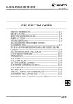
Honda
Programmed Fuel Injection
How It Works
©2006 American Honda Motor Co., Inc. – All rights reserved.
Table of Contents
Section 3 – Programmed Fuel Injection
Programmed Fuel Injection System Diagram . . . . . . . . . . . . . . . . . . . . . . . . . . . . . . . . . 3-1
Fuel Delivery System . . . . . . . . . . . . . . . . . . . . . . . . . . . . . . . . . . . . . . . . . . . . . . . . . . . 3-2
Fuel Pump . . . . . . . . . . . . . . . . . . . . . . . . . . . . . . . . . . . . . . . . . . . . . . . . . . . . . . . . . . . . 3-2
Fuel Pump Control Circuit . . . . . . . . . . . . . . . . . . . . . . . . . . . . . . . . . . . . . . . . . . . . . . . . 3-2
Fuel Filter . . . . . . . . . . . . . . . . . . . . . . . . . . . . . . . . . . . . . . . . . . . . . . . . . . . . . . . . . . . . 3-4
Fuel Line . . . . . . . . . . . . . . . . . . . . . . . . . . . . . . . . . . . . . . . . . . . . . . . . . . . . . . . . . . . . . 3-4
Fuel Injectors . . . . . . . . . . . . . . . . . . . . . . . . . . . . . . . . . . . . . . . . . . . . . . . . . . . . . . . . . 3-5
Fuel Pressure Regulator . . . . . . . . . . . . . . . . . . . . . . . . . . . . . . . . . . . . . . . . . . . . . . . . . 3-7
Idle Air Controls . . . . . . . . . . . . . . . . . . . . . . . . . . . . . . . . . . . . . . . . . . . . . . . . . . . . . . . 3-10
VFR800FI Idle Air Control . . . . . . . . . . . . . . . . . . . . . . . . . . . . . . . . . . . . . . . . . . . . . . . . 3-10
GL1800 Idle Air Control . . . . . . . . . . . . . . . . . . . . . . . . . . . . . . . . . . . . . . . . . . . . . . . . . 3-12
VTX1800 Idle Air Control . . . . . . . . . . . . . . . . . . . . . . . . . . . . . . . . . . . . . . . . . . . . . . . . 3-14
Engine Control Module (ECM) . . . . . . . . . . . . . . . . . . . . . . . . . . . . . . . . . . . . . . . . . . . . 3-15
PGM-FI Mixture Control Maps . . . . . . . . . . . . . . . . . . . . . . . . . . . . . . . . . . . . . . . . . . . . 3-15
How the Mixture Control Maps Are Used . . . . . . . . . . . . . . . . . . . . . . . . . . . . . . . . . . . .3-16
ECM Self-Diagnosis Function . . . . . . . . . . . . . . . . . . . . . . . . . . . . . . . . . . . . . . . . . . . . .3-16
Throttle Body . . . . . . . . . . . . . . . . . . . . . . . . . . . . . . . . . . . . . . . . . . . . . . . . . . . . . . . . . . 3-20
ECM Inputs & Outputs . . . . . . . . . . . . . . . . . . . . . . . . . . . . . . . . . . . . . . . . . . . . . . . . . .3-21
Basic ECM Inputs . . . . . . . . . . . . . . . . . . . . . . . . . . . . . . . . . . . . . . . . . . . . . . . . . . . . . . 3-22
Correction ECM Inputs . . . . . . . . . . . . . . . . . . . . . . . . . . . . . . . . . . . . . . . . . . . . . . . . . . 3-23
Control ECM Inputs . . . . . . . . . . . . . . . . . . . . . . . . . . . . . . . . . . . . . . . . . . . . . . . . . . . . . 3-24
ECM Outputs . . . . . . . . . . . . . . . . . . . . . . . . . . . . . . . . . . . . . . . . . . . . . . . . . . . . . . . . . 3-25
Quick Reference: Normal PGM-FI Voltage . . . . . . . . . . . . . . . . . . . . . . . . . . . . . . . . . . .3-27
Additional PGM-FI Information . . . . . . . . . . . . . . . . . . . . . . . . . . . . . . . . . . . . . . . . . . . . 3-28
Absolute Pressure . . . . . . . . . . . . . . . . . . . . . . . . . . . . . . . . . . . . . . . . . . . . . . . . . . . . . . 3-28
Knock Sensor Operation . . . . . . . . . . . . . . . . . . . . . . . . . . . . . . . . . . . . . . . . . . . . . . . . . 3-28
Emission Control Systems . . . . . . . . . . . . . . . . . . . . . . . . . . . . . . . . . . . . . . . . . . . . . . . 3-30
Catalytic Converters . . . . . . . . . . . . . . . . . . . . . . . . . . . . . . . . . . . . . . . . . . . . . . . . . . . . 3-30
Oxygen Sensor . . . . . . . . . . . . . . . . . . . . . . . . . . . . . . . . . . . . . . . . . . . . . . . . . . . . . . . . 3-31
PROGRAMMED FUEL INJECTION
PROGRAMMED FUEL INJECTION
SYSTEM DIAGRAM
Programmed fuel injection provides each cylinder
with a precise amount of fuel to mix with the
incoming air. This results in maximum fuel
economy and performance because each
cylinder is given only the fuel it needs.
To further provide for economy and performance,
the system has two computer generated maps.
One map provides fuel for low speed low load
conditions, and the other map provides fuel for
high speed high load conditions.
The diagram below presents a graphic
overview of the programmed fuel injection
system. We'll examine the fuel delivery
system first and then the engine control
module – after a brief look at the idle air
controls which are not controlled by the
ECM. Next, we'll check out the basic,
correction, and control inputs. And, finally,
the ECM control outputs.
CRANKSHAFT POSITION SENSOR
CAMSHAFT POSITION SENSOR
PROGRAMMED FUEL INJECTION
3-1
FUEL DELIVERY SYSTEM
FUEL DELIVERY SYSTEM
Fuel Pump
The fuel pump is located inside the fuel tank and
is accessible through the bottom of the tank.
Locating the fuel pump in the tank saves space
on the motorcycle and keeps the pump cooler,
preventing vapor lock. It is electrically operated
and gets its power from the battery through a fuel
cut relay. The Engine Control Module (ECM)
controls the relay in order to operate the fuel
pump.
The fuel pump operates:
• for two seconds when the key is first
turned on
• when the starter is operating
• when the engine is running
Before fuel enters the inlet side of the pump, it
must first go through a mesh filter that prevents
grit and rust from entering the pump and
damaging it.
Fuel Pump Control Circuit
The ECM controls power to the fuel pump by
switching the fuel cut relay on or off. The main
(engine stop) relay supplies power to the fuel
pump control (fuel cut) relay. The bank angle
sensor controls the operation of the engine cut
relay by completing the ground circuit.
NOTICE
When testing PGM-FI fuel pumps, always disconnect the ECM connector to
prevent possible damage to the ECM.
3-2
PROGRAMMED FUEL INJECTION
The fuel pump consist of an armature that spins
between two permanent magnets and turns an
impeller. The impeller draws fuel in and through
the pump body to the discharge port.
MAGNETS
A check valve in the pump discharge port
maintains residual pressure in the delivery
system when the engine is turned off and the
pump is not operating. Maintaining residual fuel
pressure at the injectors aids in quick engine
starting. Fuel sealed in the system can't
evaporate or deteriorate during winter storage.
PROGRAMMED FUEL INJECTION
3-3
FUEL DELIVERY SYSTEM
Fuel Pump Control Circuit (cont.)
A relief valve is located on the end of the fuel
pump. This relief valve will open if the pressure
inside the fuel pump becomes too high due to a
restricted or blocked fuel line. When it opens, the
relief valve sends fuel back into the fuel tank
preventing further pressure build up.
Fuel Filter
After leaving the pump, fuel flows through the fuel
filter. The filter's paper element is fine enough to
block particles that could cause an injector
malfunction, but not so fine that it restricts the flow
of fuel.
No replacement interval is given. Replace the fuel
filter when fuel flow is less than the service limit.
Note:
A replaceable fuel filter is not used on all models.
Check the Service Manual for the model you are
working on.
Fuel Line
On fuel injected models, the high-pressure hose
from the fuel pump to the injector fuel rail can be
damaged if it is by mishandled by bending or
stretching it too much. This damage is internal
and you will not be able to see it. When servicing
fuel injected models, avoid damaging the highpressure fuel hose. Lift the tank slowly, being
careful not to overextend the fuel hose.
3-4
PROGRAMMED FUEL INJECTION
Fuel Injectors
Fuel injectors are electrically opened on-off
solenoid valves. They are either fully closed or
fully open. The amount of fuel injected is
dependent on how long the injector is kept open.
This amount of time is referred to as the injector
discharge duration. Each injector is opened by a
signal from the ECM. Fuel is only injected when it
is needed – during each cylinder's intake stroke.
This is referred to as sequential fuel injection.
Inside the injector there's a spring-loaded plunger
that closes against a valve seat. Once seated,
the flow of fuel is blocked. When the solenoid coil
within the injector assembly lifts the plunger, the
pressurized fuel sprays into the cylinder. The
battery supplies the power for the solenoid coil.
The injector solenoid coils are a switch to ground
circuit. The ECM provides an electrical ground
when it determines the injector should be
opened.
The injector tip's opening is designed to provide a
spray pattern that atomizes the fuel to help it mix
with the incoming air.
PROGRAMMED FUEL INJECTION
3-5
FUEL DELIVERY SYSTEM
Fuel Injectors (cont.)
In 2001 a new type of injector was introduced on
some models. This is a multi-outlet design with a
ball shaped plunger in place of the tapered
needle plunger. Both four and twelve outlet
injectors are used in the new Programmed Fuel
Injection (PGM-FI) models. These provide a finer
spray of fuel for better atomization.
The choice of injector type is based on
performance, cost and availability at the time of
development.
Injectors can have two types of failures; electrical
and mechanical.
There are three possible electrical failures for an
injector:
Four Outlet Injector
• High resistance
• An open
• A short
Some models detect electrical failure while
running. Others detect it only on start up. The MIL
switches on and the engine stops when an
injector failure is detected.
There are two possible mechanical failures for an
injector:
• Leaking fuel (partial or complete)
• Blocked fuel discharge (partial or complete)
Twelve Outlet Injector
Possible fuel leakage is indicated by:
• Dark spark plug color
• Fuel fouled spark plugs
Blocked fuel discharge is indicated by:
• A cold exhaust pipe on that cylinder
3-6
PROGRAMMED FUEL INJECTION
Fuel Pressure Regulator
A fuel pressure regulator is used to maintain fuel
pressure. The regulator is mounted to the fuel rail
and has a return line to the fuel tank. Excess fuel
in the fuel rail flows back to the tank. Fuel
entering the tank from the return line passes
through a stainless steel wool pad to remove air
bubbles.
PROGRAMMED FUEL INJECTION
3-7
FUEL DELIVERY SYSTEM
Fuel Pressure Regulator (cont.)
To understand the fuel pressure requirements of
fuel injection systems, start by looking at the
conditions at both ends of the injector. The output
end of the injector points into an intake port. In
order to spray fuel into the intake port the
pressure on the supply end of the injector must
be greater than the intake manifold pressure.
When the engine is running, a vacuum exists in
the intake ports. This is measured in inches or
millimeters of Mercury (Hg). A normal motorcycle
idle vacuum pressure is about one inch of Hg., or
4.9 psi.
Fuel pressure is typically in the range of 32 - 50
psi. The GL1800, for example, uses a fuel
pressure of 50 psi. That is the pressure difference
between inlet port vacuum pressure and fuel
pressure as shown below. The fuel pressure is
set at a fixed amount above the inlet port vacuum
pressure. Therefore, changes in inlet port
vacuum pressure have no effect on the amount
of fuel that an injector delivers when it is opened
for a specific amount of time.
3-8
PROGRAMMED FUEL INJECTION
A spring presses the regulator valve closed and
inlet port vacuum pressure pulls the valve open.
These two forces balance to give a continuously
changing fuel pressure that is a specified amount
above inlet port pressure.
Note:
Some models have a fuel pressure test port,
others require a pressure test banjo bolt. Check
the Service Manual for the vehicle you are
working on.
PROGRAMMED FUEL INJECTION
3-9
IDLE AIR CONTROLS
IDLE AIR CONTROLS
Let’s look at three different idle air control
systems used on PGM-FI models:
• VFR800FI
• GL1800
• VTX1800
VFR800FI Idle Air Control
A starter enrichment valve controls airflow to
each cylinder at idle speeds. The starter
enrichment valves allow air to bypass the throttle
valves at idle to keep the engine running and
provide a fast idle for engine warm up. The
VFR800FI is unique because the starter
enrichment valves are adjusted to different
vacuum readings to compensate for differences
in exhaust length between cylinders.
AIR CLEANER CASE
STARTER ENRICHMENT VALVE
When the starter enrichment valves are open, air flows from the air cleaner case,
past each starter enrichment valve into each intake port.
3-10
PROGRAMMED FUEL INJECTION
Fast idle function is obtained by opening the air
valves further, allowing more air to enter the
engine. On '98 and '99 models, a choke lever
opens the starter enrichment valves.
On 2000 and later models, the starter enrichment
valves are open a predetermined amount at cold
engine condition for fast idle. A thermowax
mechanism is used to automatically close the
starter enrichment valves gradually, based on
engine temperature. Engine coolant heats the
thermowax pellet, causing it to expand and close
the starter enrichment valves.
Starter enrichment valve synchronization is
required after disassembly of the throttle body, or
if the idle becomes rough or uneven. The starter
enrichment valve for cylinder 1 is the base and is
non-adjustable. There is no scheduled
maintenance interval for starter enrichment
valve synchronization.
PROGRAMMED FUEL INJECTION
3-11
IDLE AIR CONTROLS
GL1800 Idle Air Control
The idle air control (IAC) valve, operated by the
ECM, controls the volume of air that enters the
engine during idle to maintain an even idle speed.
It controls idle speed fluctuations and adjusts the
basic idle speed by supplying air to the intake
manifolds according to the:
• engine coolant temperature
• alternator load
• throttle valve position
The IAC also controls fast idle by providing more
air to the engine during warm up.
An electromagnetic coil attracting a permanent
magnet on the end of the IAC shaft rotates the
IAC valve shaft. As voltage in the
electromagnetic coil is reversed, the valve rotates
in opposite directions to increase or decrease
idle airflow.
TURN
CLOCKWISE
3-12
PROGRAMMED FUEL INJECTION
TURN
COUNTER
CLOCKWISE
Two air screws control 50% of idle airflow in
parallel with the IAC to each manifold. They are
used to adjust idle airflow for changes in engine
operation over time.
The ECM initializes the idle speed whenever the
engine is started and left to idle for several
minutes. If the throttle is opened or the motorcycle
is ridden before the initialization process is
complete, the existing settings will be used.
PROGRAMMED FUEL INJECTION
3-13
IDLE AIR CONTROLS
VTX1800 Idle Air Control
The VTX1800 uses a single thermowax
controlled valve to supply idle air to both
cylinders. Air screws are also used to balance the
amount of air entering each cylinder.
The air flowing into each cylinder at idle is
balanced by adjusting the airscrews.
Throttle Body (Slow System)
REAR
CYLINDER
AUTO CHOKE SYSTEM
(THERMO WAX ACTIVATED)
FRONT ADJUST
SCREW
REAR ADJUST
SCREW
Lock nut factory adjusted (do not remove).
THROTTLE STOP SCREW
3-14
FRONT
CYLINDER
PROGRAMMED FUEL INJECTION
ENGINE CONTROL MODULE
(ECM)
The ECM uses a 16-bit single chip
microcomputer to process the data and control
the operation of fuel injectors, ignition timing, fuel
pump and air intake door. The ECM collects
information from the basic input sensors:
• Crankshaft position sensor
• Camshaft position sensor
• Throttle position (TP) sensor
• Manifold absolute pressure (MAP) sensor
From these inputs the ECM determines which
basic discharge duration map to use and a basic
discharge duration value in milliseconds. That
is the length of time the injector is open to deliver
fuel.
PGM-FI Mixture Control Maps
Two types of fuel control maps are used to
determine the basic discharge duration. Some
engines will have separate versions of both types
of map tailored to the needs of each cylinder or
bank of cylinders.
For low load / small throttle opening operation, a
speed-density map is used. This map determines
basic injection volume based on inputs of intake
manifold pressure and RPM.
Speed Density Map
FUEL
VOLUME
HIGH
ABSOLUTE
PRESSURE
LOW
HIGH
RPM
Speed Throttle Map
For high load / larger throttle openings, a speedthrottle map is used. The inputs here are throttle
position and RPM.
FUEL
VOLUME
HIGH
THROTTLE
POSITION
PROGRAMMED FUEL INJECTION
LOW
HIGH
RPM
3-15
ENGINE CONTROL MODULE (ECM)
How the Mixture Control Maps Are
Used
The ECM looks at engine RPM, throttle position,
and manifold pressure. Based on throttle position,
one of the maps is selected, then the variables of
engine speed and manifold pressure or engine
speed and throttle position are used to select a
specific point on the map. The intersection of
these two values gives a vertical line for the basic
discharge duration shown here.
The basic discharge duration value is modified
based on input from the correction sensors:
• Engine coolant temperature sensor (ECT)
• Intake air temperature sensor (IAT)
• Barometric pressure sensor (BARO)
Each of these corrections can increase or
decrease the amount of fuel injected. The mixture
map selection can be based on input from
the following:
• Vehicle speed sensor
• Gear position switch
Under certain conditions, engine operation is
adjusted based on these control inputs:
• Oxygen (O2) sensor
• Knock sensor
• Bank angle sensor (stops, but does not adjust
engine operation)
ECM Self-Diagnosis Function
Various components of the PGM-FI are
monitored by the self-diagnosis function of the
ECM.
All PGM-FI components are constantly monitored
during operation - except fuel injectors on some
models. For example, the fuel injectors for the
2001 GL1800 are diagnosed only at start up while
the fuel injectors for the 2002 and later GL1800’s
are diagnosed constantly during operation.
3-16
PROGRAMMED FUEL INJECTION
BASIC DISCHARGE DURATION
If the ECM diagnoses a fault, the Malfunction
Indicator Lamp (MIL) lights and remains on to
notify the rider of a problem.
When the MIL lights, the fail-safe program in the
ECM will affect engine operation in one of
two ways:
• Engine stops, won't restart
• Engine continues to run with reduced
performance
Refer to the symptoms column of the MIL Failure
Codes table on page 3-18.
Malfunction Indicator Lamp (MIL)
For PGM-FI troubleshooting, diagnosis of failures
is provided through a Malfunction Indicator Lamp
(MIL). While operating the engine at less than
5,000 rpm with the side stand down, the MIL will
blink out a fault code. The MIL blinks to indicate
the fault. There are long blinks (1.3 seconds) and
short blinks (0.5 seconds). A long blink
represents the number 10. Short blinks indicate 1
through 9. Therefore, one long blink and three
short blinks indicate 13. This fault code can then
be looked up in the Service Manual and by
following the provided instructions, diagnosed
quickly.
The self-diagnosis feature can only detect failures
electrically, therefore it will not detect all of the
problems you may encounter.
PROGRAMMED FUEL INJECTION
3-17
ENGINE CONTROL MODULE (ECM)
ECM Self-Diagnosis Function (cont.)
MIL FAILURE CODES
MIL
Code
Part
Condition
1
MAP Sensor
Output voltage is out of specified range continuously
for specified duration.
Use Throttle Map
Poor idling and low
throttle operation.
2
MAP Sensor
Vacuum Tube
MAP voltage does not change before and after
engine started.
Use Throttle Map
Poor idling and low
throttle operation.
7
ECT
Output voltage is out of specified range continuously
for specific duration.
Use fixed temperature
value
Hard to start when cold.
Cooling fan runs if
controlled by ECM.
(See Note)
8
Throttle
Output voltage is out of specified range continuously
for specific duration.
Opening zero
Poor response
when accelerating.
9
IAT
Output voltage is out of specified range continuously
for specific duration.
Use fixed temperature
value 20 degrees C.
Poor hot engine starting.
10
BARO
Output voltage is out of range continuously for
specific time.
Use sea level
Poor performance at
high altitude.
11
Vehicle Speed
Gear is not in Neutral, engine rpm is high, but vehicle
speed signal pulse does not input.
No compensation for
each gear position
A little poor driveability.
12
Injector
Voltage not applied to ECM terminal.
Fuel injection and
ignition shut down.
Engine stop.
18
Camshaft
position sensor
No signal from cam though there is crank pulse input.
Fuel injection and
ignition shut down.
Engine stop.
19
Crankshaft
Pulse
Generator
No signal from crank though there is cam pulse input.
Fuel injection and
ignition shut down.
Engine stop.
20
ECM-EEPROM
Failure in reading/writing EEPROM in ECM.
21
Oxygen Sensor
No voltage from oxygen sensor.
Stop feedback control
No noticeable problem.
23
Oxygen Sensor
Heater Voltage is not applied to ECM terminal.
Stop feedback control
No noticeable problem.
25
Knock Sensor
No signal input though engine rpm is higher than a
specified speed.
Ignition timing retard
Poor engine performance.
29
Idle Air Control
Valve
Voltage is not applied to ECM terminal.
Stop control
Unstable idling.
33
ECM-EEPROM
Failure in reading/writing EEPROM in ECM.
41
Gear Position
More than 2 gear position signals at a time, or
mismatched to gear position calculated with vehicle
speed and engine speed.
Fail-Safe Action
Symptom
Malfunction history
cannot be read.
Malfunction history
cannot be read.
Stop compensation
Poor driveability.
Note: On some models with fans that blow forward, the fans stop when vehicle speed exceeds
a specific speed (example: 12 mph).
3-18
PROGRAMMED FUEL INJECTION
Fail Safe Operation
If the ECM self diagnosis detects a failure with a
PGM-FI component it will either stop the engine
or use a stored value for the input that is not
available. The components in the PGM-FI system
can be grouped in two categories, essential and
non-essential.
Essential components must all function for
engine operation:
• Crankshaft position sensor
• Camshaft position sensor
• Injectors
If any of these components fail, the engine will
stop, or it will not restart after the key is turned
off. Fuel injection, ignition and fuel pump
operation will be prevented.
Non-essential components with back-up for failsafe operation are:
•
•
•
•
•
•
•
•
•
•
•
•
•
Throttle Position Sensor
Oxygen Sensor Heater
Manifold Absolute Pressure Sensor
Knock Sensor
Engine Coolant Temperature
Idle Air Control Valve
Intake Air Temperature
Gear Position
BARO Sensor
PAIR Solenoid Valve
Vehicle Speed Sensor
Evap Solenoid Valve
Oxygen Sensor
Each of these components has a back-up or failsafe fixed value that allows the vehicle to be
ridden to a dealership for service.
PROGRAMMED FUEL INJECTION
3-19
ENGINE CONTROL MODULE (ECM)
Throttle Body
Most models with PGM-FI have a throttle valve
for each cylinder. An exception to this is the
GL1800 that uses a single throttle valve for each
bank of three cylinders. In all cases the throttle
sensor is non-adjustable and the throttle body
must be replaced if the throttle sensor fails.
NOTICE
Do not attempt to remove or re-adjust bolts and
nuts which are painted white. It is nearly
impossible to reset the throttle sensor to the
proper position.
The yellow painted bolts and screws can be
removed, but must be tightened to the
specified torque.
3-20
PROGRAMMED FUEL INJECTION
Each throttle valve and the surrounding area of
the throttle bore are coated with a molybdenumsealant to assure sealing between the throttle
valve and the throttle body.
NOTICE
Do not attempt to remove this sealant. Removal
will cause air leakage, resulting in rough idle.
Clearing a Flooded Engine
If the rider floods the engine, the PGM-FI system
has a feature that will assist in restarting the
engine. If the throttle is held wide open when
starting the engine, no fuel will be injected.
SEALANT
ECM INPUTS & OUTPUTS
The engine control module has three types
of inputs:
• Basic
• Corrective
• Control
The basic inputs provide the information the ECM
needs to select one of the two (high or low speed)
mixture control maps, and then select the basic
fuel discharge duration from the chosen map.
The correction inputs provide the information the
ECM needs to adjust the basic fuel discharge
duration.
Two control inputs provide the information the
ECM needs to adjust engine operation. A third
control input (the bank angle sensor), rather than
providing information to the ECM, instead cuts off
electrical power to the ECM. This stops the engine.
PROGRAMMED FUEL INJECTION
3-21
ECM INPUTS & OUTPUTS
Basic ECM Inputs
Sensor
Measures
Signal
Component
Comment
Crankshaft
Position Sensor
Engine
Speed
Spiked Wave (AC)
The PGM-FI system cannot
operate without this input.
Measure this voltage signal with a
peak voltage tester.
Camshaft
Position Sensor
TDC of
Cylinder
No. 1
Spiked Wave (AC)
The PGM-FI system cannot
operate without this input.
Identifies cylinder 1 for sequential
injection during each intake
stroke. Measure voltage signal
with a peak voltage tester.
Throttle
Position (TP)
Sensor
Throttle
Setting
Analog (DC)
Mounted on the end of the throttle
shaft. Sensor voltage varies with
throttle opening.
Idle: about 0.5 volts.
Full open: about 4.5 volts.
Sensor is not adjustable.
Throttle body must be replaced if
it fails.
Manifold
Absolute
Pressure
(MAP) Sensor
Vacuum
pressure in
the intake
manifold
Analog (DC)
Voltage from the MAP sensor
increases with absolute pressure.
With key on and engine off,
voltage from the map sensor is
2.3 to 3.0 volts. Compare this
output with the BARO sensor
output, with key on, engine off.
They should be very similar.
Note: Some models also use the
MAP sensor on startup to
measure atmospheric pressure.
No BARO sensor is used.
3-22
PROGRAMMED FUEL INJECTION
Correction ECM Inputs
Sensor
Measures
Signal
Component
Engine
Coolant
Temperature
(ECT)
Sensor
Engine
Temperature
Analog (DC)
This sensor measures engine
coolant temperature. The output
voltage decreases as the
temperature increases. At 70
degrees F the output voltage is
2.8 to 3.0 volts. Compare this
output voltage to the IAT sensor
when the engine is cold. They
should be similar.
Intake Air
Temperature
(IAT) Sensor
Temperature
in air cleaner
case
Analog (DC)
This sensor measures
temperature in the air cleaner
case. The IAT sensor has a
plastic case that allows it to
respond quickly to changes in
air temperature. At 70 degrees F
the output voltage is 2.8 to 3.0
volts. Compare this output
voltage to the ECT sensor when
the engine is cold. They should
be similar.
Barometric
Pressure
(BARO)
Sensor
Atmospheric
Pressure
Analog (DC)
This sensor measures
atmospheric pressure. Its input
allows the ECM to adjust the
air/fuel mixture for changes in
altitude. The output voltage with
the key on and engine off is 2.3
to 3.0 volts. Compare this
sensor’s output with the MAP
sensor under the same test
conditions. They should have
similar output voltages. A MAP
sensor part is frequently used as
the BARO sensor.
Vehicle
Speed
Sensor
Road Speed
Digital (DC)
The vehicle speed sensor input is
used to switch the cooling fans off
at 12 mph on the GL1800.
Gear
Position
Switch
Gear
Position
N/A
Gear position is supplied to the
ECM in order for it to select the
correct ignition map for the gear
selected. The GL1800 has
separate ignition maps for
neutral, 1st, 2nd, 3rd, and above.
PROGRAMMED FUEL INJECTION
Comment
3-23
ECM INPUTS & OUTPUTS
Control ECM Inputs
Sensor
Measures
Signal
Oxygen (O2)
Sensor
Oxygen in
exhaust
Analog (DC)
Knock
Sensor
Detonation
Bank Angle
Sensor
Vehicle
position
Component
Comment
An oxygen sensor produces its
own voltage: Nearly a full volt if it
senses very little oxygen, when
the mixture is rich. Close to zero
when the mixture is too lean and
there is excessive oxygen. About
a half volt when the mixture is
just right.
The knock sensor detects
detonation and from this input the
ECM retards the ignition timing.
N/A
The bank angle sensor controls
the operation of the engine-stop
relay and the fuel-cut relay. The
sensor consists of a reed switch,
latch-up circuit and an oil
dampened pendulum with
two magnets.
Upright
When the ignition switch is turned
on, power flows through the
latch-up circuit turning the
transistor on, then current flows
through the coil of the enginestop relay to ground.
When the motorcycle and sensor
are tipped more than 50 degrees,
the magnet in the sensor
pendulum closes the reed switch.
This causes the latch-up circuit to
turn off the transistor, opening the
circuit between the engine-stop
relay and ground. This stops
power to the ECM.
Tipped Over
3-24
PROGRAMMED FUEL INJECTION
To reset the sensor, turn the
ignition key switch off before
attempting to restart the engine.
ECM Outputs
The ECM controls fuel injection, ignition spark,
and the operation of idle air control valve, fuel
pump, purge control solenoid, and cooling fan.
Fuel Injectors
Fuel injectors are supplied power from the main
relay. The ECM grounds the injector to operate it.
See fuel delivery system, fuel injectors, page 3-5.
Ignition Coils
The ignition coils are connected to the ECM.
Each GL1800 ignition coil has a built-in igniter
that boosts the ignition signal (5V) from the
engine control module (ECM) to generate the
primary side voltage.
The fuel pump relay is activated by the ECM. Its
power is supplied by the main relay which is
controlled (on its ground side) by the bank angle
sensor. The ignition switch and handlebar ignition
switch power the main relay.
Idle Air Control Valve (GL1800)
See idle air controls, GL1800, page 3-12 for an
explanation of operation.
Fuel Cut (Fuel Pump Control) Relay
The fuel cut relay is powered from the engine
control relay and controlled by the ECM. The ECM
switches on the relay to operate the fuel pump.
PROGRAMMED FUEL INJECTION
3-25
ECM INPUTS & OUTPUTS
ECM Outputs (cont.)
Purge Control Solenoid
The purge control solenoid opens and closes the
purge control system to vent fuel vapors into the
intake system.
Fan Control Relay
The fan control relay controls power to the
cooling fan and is switched on and off by the
ECM. This replaces the thermoswitch used to
control fan operation on other models.
3-26
PROGRAMMED FUEL INJECTION
QUICK REFERENCE:
NORMAL PGM-FI VOLTAGE
Normal Voltage
Component
Power Into ECM
Key On Engine Off
Hot
Battery voltage
Battery voltage
Ignition Pulse
Min. 0.7 peak voltage when cranking
Cam Pulse
Min. 0.7 peak voltage when cranking
MAP Sensor Output
2.2 - 2.95 V *
Lower voltage
Throttle Sensor Output
0.50 V throttle closed
0.5 - 4.8 V
ECT Sensor Input Voltage
2.8 - 3.0 V at 70° F
Lower voltage
IAT Sensor Input Voltage
2.8 - 3.0 V at 70° F
Lower voltage
BARO Sensor Output
2.2 - 2.95 V *
Lower voltage
Fuel Cut Relay
Battery voltage
Lower voltage
Intake Duct Control Solenoid Valve
Battery voltage
Lower voltage
Control Solenoid Valve (CA only)
Battery voltage
Lower voltage
Pair Solenoid Control Valve
Battery voltage
Lower voltage
O2 Sensor Heater
Battery voltage
Lower voltage
O2 Sensor Output
Varying voltage 0.2 - 0.9 V
Vehicle Speed Sensor
0 to 5 V as wheel is rotated
Key On Engine Off Hot
*Barometric pressure varies with elevation. Use the values below if your dealership is above
sea level.
Sea level – 1000 ft. 2.8 - 2.95 V
1000 – 3000 ft. 2.55 - 2.8 V
3000 – 7000 ft. 2.2 - 2.6 V
PROGRAMMED FUEL INJECTION
3-27
ECM INPUTS PGM-FI
ADDITIONAL
& OUTPUTS
INFORMATION
ADDITIONAL PGM-FI
INFORMATION
Absolute Pressure
In school science class you probably learned that
the atmosphere exerts a pressure of 14.7 pounds
per square inch (psi) at sea level. You probably
learned that any pressure below 14.7 psi is a
vacuum, but what if the vacuum was -14.7 psi?
That would be a perfect vacuum, what scientists
describe as absolute zero pressure. Now, we're
not interested in measuring that much vacuum,
but the engineers at Honda R&D felt that
measuring pressure on a scale without positive
and negative values would be a better method. It
allows the sensors to measure inlet port vacuum,
atmospheric and even, boost pressure above
atmospheric on the same scale.
Knock Sensor Operation
The knock sensor detects detonation and from
this input the ECM retards the ignition timing.
3-28
PROGRAMMED FUEL INJECTION
Detonation above the designated limit can damage the
engine. Therefore it’s important to minimize any
detonation before damage can occur.
Retarding the ignition timing when excessive detonation
is detected prevents possible engine damage.
PROGRAMMED FUEL INJECTION
3-29
ECM INPUTS PGM-FI
ADDITIONAL
& OUTPUTS
INFORMATION
Emission Control Systems
The ideal “combustion” process of a 4-stroke
engine converts fuel to oxygen (O 2 ) and water
vapor (H 2 O). In reality, the combustion is not ideal.
The engine produces some additional exhaust gas
components:
• HC: hydrocarbons
• CO: carbon monoxide
• CO 2 : carbon dioxide
• NOx: oxides of nitrogen
Catalytic Converters
The catalytic converter reduces the amount of
exhaust emission gases in the exhaust gas by
helping the chemical reaction called “oxidization”
to be more efficient. The toxic CO, HC and NOx
emission components in the exhaust gas are more
efficiently converted to CO2 , di-nitrogen (N 2 ), and
water vapor.
In cars, the platinum / radium “monolith type”
catalytic converter is mounted in the center of the
exhaust pipe under the car. On motorcycles, it is
installed just before the “pre-chamber.”
The “Three-Way” Type Catalytic Converter
Motorcycles use a regulated air-fuel mixture
control system, sensing the exhaust gas
composition by means of an oxygen sensor (also
called O2 sensor or “Lambda” sensor) in the
exhaust. The VFR uses dual O2 sensors.
3-30
PROGRAMMED FUEL INJECTION
Oxygen Sensor
The oxygen (O2 ) sensor measures the percent of
oxygen in the exhaust gas. The fuel injection is
continuously adjusted to inject more or less fuel,
keeping the amount of oxygen consistently at a
level where the lowest amount of toxic gases is
produced.
This air/fuel ratio is called the stoichiometric
ratio. (Theoretically, this is the A/F ratio for
complete combustion.) With the air-fuel ratio
controlled around this point by the oxygen
sensor, the remaining toxic compounds in the
exhaust gas are more efficiently converted to
non-toxic compounds.
How Does This Work?
The O 2 sensor uses a hollow, closed-end shaft of
zirconium dioxide with platinum-plated inner and
outer surfaces. The inner surface is open to the
atmosphere and the outer surface is exposed to
exhaust gas flow through the manifold.
The oxygen sensor converts the difference in
oxygen density between the inner and outer
surfaces into electromotive force, and transmits a
voltage signal to the ECM to control the air-fuel
ratio.
STOICHIOMETRIC RATIO
A/F CONTROL ZONE
O2 SENSOR
OUT PUT
VOLTAGE
This type of oxygen sensor must be heated to a
particular temperature to operate normally.
HARMLESS
GAS
REDUCTION
RATIO
A/F Ratio
PROGRAMMED FUEL INJECTION
3-31
ECM INPUTS PGM-FI
ADDITIONAL
& OUTPUTS
INFORMATION
Oxygen Sensor (cont.)
Why Must Some O2 Sensors Be Heated?
In multi-cylinder engines, the oxygen sensor is
insufficiently heated by the exhaust gases
because of its remote position from the exhaust
ports. For this reason, an electric heating element
is incorporated in the sensor to allow it to
measure the average value of all cylinder gases.
Troubleshooting the O2 Sensor
The O2 sensor creates a signal between 0.1 and
1.0 volts, depending on the air / fuel ratio (or socalled Lambda value).
• If the mixture is “RICH,” sensor voltage is
“HIGH” (1.0 V)
• If the mixture is “LEAN,” sensor voltage is
“LOW” (0.1 V)
This can be best monitored during engine
operation (while “snapping” the throttle), using an
ANALOG voltmeter or oscilloscope.
While accelerating, the mixture is “RICH” for a
moment, immediately returning to “LEAN” again.
This should be clearly reflected by the change of
sensor output voltage.
The O2 sensor-heating element is essential for
the operation of the system. It can be checked
statically by measuring its resistance value.
However, the “control system” (ECU) should be
checked.
This activity can be best monitored during engine
operation: the voltage across the heating element
is switched ON and OFF by the ECU at a certain
rhythm.
An analog meter (IMRIE tester or IgnitionMate) is
more useful for this kind of “dynamic” monitoring
during operation.
3-32
PROGRAMMED FUEL INJECTION