1
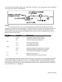
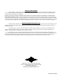
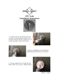
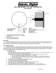
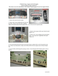
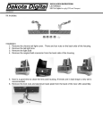
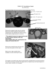
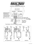
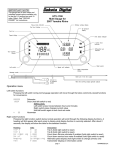
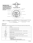
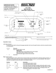
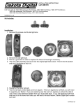
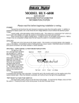
STM-100
Data Bus Breakout for 2004 – 2010 Harley Davidson models
The STM-100 can be used to simplify the installation of an aftermarket speedometer and/or
tachometer on a 2004 – 2010 Harley Davidson motorcycle. The device converts the signals from the
data bus into traditional analog signals for a gauge of your choice. Outputs are provided for accessory
power and ground, tachometer signal (adjustable for 1, 2 or 4 cylinder outputs), speedometer signal
(8,000ppm) in addition to the Check Engine signal, normally only available on the data bus. The STM100 plugs directly into the diagnostics port and reads the signals from the ECM so there are no additional
sensors to wire.
In addition to the wired outputs, the STM-100 has an LED display that allows you to read and
clear diagnostic trouble codes, similar to a scan tool.
Included in the kit you should find:
Heat Shrink
Manual
STM-100
Power Harness
Signal Harness
WIRING
Locate the four-pin diagnostic plug, typically found under the seat or side cover near the ECM.
The STM-100 will plug directly into the diagnostic plug. This will provide the power, ground, and data
into the STM-100.
*** Note: If you ever need to perform diagnostics or re-flash an ECM at a shop or dealer, unplug the STM100 to gain access to the diagnostic plug, after the work has been performed simply reconnect the STM100 to the diagnostic plug. All of your previous settings in the STM-100 are saved, so removing or
unplugging will not affect the setup.
MANUAL # 650324
MPH
5 6 7 8
3 4
RPM x1000
1 2
MPH
STM-100
Data Bus Break Out
2 Pin Connector
RED - +12V Out (key on)
BLACK - Ground
3 Pin Connector
Attached
Harness
www.dakotadigital.com
[email protected]
605-332-6513
To diagnostic plug
YELLOW - Tach (1/ 2/ 4 cyl)
WHITE/BLUE - Check Engine (ground when active)
GRAY - Speed (8k PPM)
There are two separate harnesses that plug into the front of the STM-100. You will need to look
at the instruction for your gauge and connect the STM-100 wires to the appropriate wire.
The two wire harness provides +12V keyed power out and ground for the gauge being added.
RED
+12V Keyed accessory power out (2 amps max)
BLACK
Ground
The three wire harness provides tach, check engine, and speed signal outputs.
YELLOW
Tach output ( 1, 2, or 4 cylinder output)
WHITE w/ BLUE
Check engine, provides a ground when activated
GRAY
Speed signal out (8000 pulse per mile signal)
The heat shrink supplied with the kit can be used to cover the wires between the STM-100 and gauge
being installed for a “cleaner” looking installation.
Wiring an external check engine light if your aftermarket gauge doesn’t have one can be done fairly
easily. The STM-100 will provide a ground signal whenever the check engine light is active or on. This
is how you would wire a small 12V lamp as a check engine indicator.
MANUAL # 650324
If you need the check engine output to be “active high” or provide a +12V voltage when active a standard
12V relay can be used to accomplish this.
30
85
86
DO NOT CONNECT
87
SETUP
The setup menus allow you to access the diagnostic capabilities of the STM-100 as well as
allowing you to setup the tach output signal. Pay close attention to settings in these menus as incorrect
settings could result in an incorrect reading at the gauge. Also know that you will still need to setup
and/or calibrate the gauge that is being installed so you will have to refer to the gauge instructions for
signal requirements and setup.
Main Menu
Sub Menu
Description___________________________
engIne
seCure
abs
read engine codes and part number
read security codes and part number
read abs codes and part number
CyL 1
CyL 2
CyL 4
one cylinder tach output
two cylinder tach output
four cylinder tach output
speed
taCh
none
STM-100 simulates a speedometer connected
STM-100 simulates a tachometer connected
STM-100 does not simulate a stock gauge
st01
Software code revision
Exit setup and return to normal operation
DIag
TaCh
Gauge
Info
donE
To enter setup press and hold the switch then turn the key on, the switch is on the right side of the STM100 located just below the three wire connector. The display will light up and read “888888” while the
switch is held, release the switch and you are now in the setup menus. Press and release the switch to
scroll through menus and options. Press and hold the switch to make a selection and save a setting, or
exit a menu when “donE” is displayed.
MANUAL # 650324
Diagnostics (diaG)
The diagnostic menu doesn’t necessarily require any setup it is used for diagnostic purposes. To
enter diagnostics mode, make sure the “run” switch is in the “ON” position, press and hold the switch on
the STM-100 while turning the key on. Once the key is on, release the switch and “diaG” should be
displayed. Press and hold the switch until “ -- ” is displayed, then release the switch to enter the
diagnostic menus.
Press and release the switch to scroll through the three diagnostic modules; engine, security and
ABS. When you are on the desired module, press and hold the switch until “ -- ” is displayed, then
release the switch. If there are any trouble codes you will see them displayed or “none” if no codes are
present. Press and release the switch to see if there are any other codes on the current module.
Example: If you select engIne and there is a problem with the MAP sensor you could see “P0107" on
the display; looking at a service manual yields a MAP sensor Open/Low. The codes are displayed as a
letter followed by four numbers.
Please check a service manual for more code descriptions. Each module can be checked
independently for codes. Whenever a code is displayed, a press and hold will clear the current code.
If a module isn’t present or the bike doesn’t have the option, you will get a “no rSP” message. If
you think you got the message in error, check that the run switch is in the “ON” position and try again, or
check fuses and connection at the various modules.
***Please consult a factory service manual for more information on DTC, diagnostic trouble codes,
and troubleshooting procedures.
Tach signal setup (taCh)
This menu will allow you to select from three different tach output frequencies; one cylinder, two
cylinder, and four cylinder. To enter setup, press and hold the setup switch on the STM-100 and turn the
key on, release the switch. Press and release the switch until you get to the “tACh” setup menu. When
at the “tACh” menu, press and hold the switch until “ -- ” is displayed, then release the switch to enter
the tach cylinder selection.
Press and release the switch to select an output from “CYL 1” for one cylinder, to “CYL 2” for two
cylinder, and “CYL 4” for a four cylinder output.
When the desired setting is displayed, press and hold the switch until “ -- ” is displayed.
Release the switch and the next menu will be displayed.
*** Note: some tachs may require calibration at the tachometer to select appropriate input signal type so
please make sure cylinder counts are matched up appropriately.
Gauge bus simulator (GAUGE)
The gauge menu is not a critical menu, but it will allow the STM-100 to simulate and send data
out on the bus to “trick” the bike into thinking it has a stock gauge still in place. This will prevent some
trouble codes from appearing, but these codes have not been known to cause any problems other than
setting the code as more of a status indicator that a gauge isn’t connected.
If you are replacing or removing the stock speedometer, you will want to select the “speed” option
so the STM-100 will transmit some data back to the data bus to “trick” the bike into thinking it still has a
stock speedometer present.
If the stock speedometer is still connected on the bike, you shouldn’t have to worry about setting
this menu and the default selection should be the “none” option. Since there is a stock gauge connected,
the STM-100 doesn’t need to simulate that any gauge is connected.
MANUAL # 650324
If you are just adding a tachometer to your bike that didn’t have one, you will also want to select
“none” option as the bike should already be receiving info from the stock gauge.
The “taCh” option doesn’t seem to be a critical or high priority message. This option may need to
be enabled in a rare case but typically selecting “speed” if a stock gauge is being removed, or “none” if a
stock gauge is remaining in place on the bike would be the most common selection.
To enter setup, press and hold the setup switch on the STM-100 and turn the key on; release the
switch. Press and release the switch until you get to the “GAUGE” setup menu. When at the “GAUGE”
menu press and hold the switch until “ -- ” is displayed, then release the switch to enter the gauge bus
simulator selection.
Press and release the switch to select a simulated bus output; “SPEED”, “tACh” , or “none”.
When the desired setting is displayed, press and hold the switch until “ -- ” is displayed.
Release the switch and the next menu will be displayed.
Information menu (InFo)
This menu is used for diagnostic purposes and can verify the current revision of software on your
STM-100 should an update ever be needed. To access the menu, press and hold the setup switch on
the STM-100 and turn the key on, release the switch. Press and release the switch until you get to the
“InFo” setup menu. When at the “InFo” menu, press and hold the switch until “ -- ” is displayed, then
release the switch. The current software code will be displayed “Stxx”, where “xx” is the current code
number. This code may be needed if you call in for tech support, so it may be helpful to retrieve it prior
to calling.
NORMAL OPERATION
Typically, the STM-100 will end up getting stashed away under a side cover and not really looked
at other than for set up and diagnostic. In normal operation the STM-100 uses some of the decimal
points on the display to indicate that it is working properly.
The top left decimal is used to show the check engine light status. If lit, there is a trouble code
present. The decimal at the top middle of the display is used to show that the STM-100 is powered and
receiving data. LED on steady represents the unit is getting power but no data from the bus. If the
decimal is flashing, that represents data is present and the unit is functioning properly.
If you press hold the switch, after the key has been turned on, the display will turn on and show
speed and tach values that it is receiving from the bus. Depending on gearing and what is done to the
bike, the speed value may be irrelevant and could vary from the actual speed. The speed value is also
displayed in km/h as this is what the data bus actually sends out for data. The RPM value is actual, and
it can be used to compare to the tachometer reading of the installed tach to verify settings are correct.
The display will switch from speed and tach as long as the switch is held, as soon as the switch is
released it will shut off and just the status decimals will be flashing.
Speed display
“S 120"
this reading is in km/h (to convert to mph take reading /1.61=mph)
For this example 120 km/h / 1.61 = 74.5 mph
Tach display
“r 5320"
this reading is actual RPM data
For this example 5320 RPMs
MANUAL # 650324
SERVICE AND REPAIR
DAKOTA DIGITAL offers complete service and repair of its product line. In addition, technical consultation is available to help you
work through any questions or problems you may be having installing one of our products. Please read through the Troubleshooting Guide.
There, you will find the solution to most problems.
Should you ever need to send the unit back for repairs, please call our technical support line, (605) 332-6513, to request a Return
Merchandise Authorization number. Package the product in a good quality box along with plenty of packing material. Ship the product by
UPS or insured Parcel Post. Be sure to include the RMA number on the package, and include a complete description of the problem with RMA
number, your full name and address (street address preferred), and a telephone number where you can be reached during the day. Any returns
for warranty work must include a copy of the dated sales receipt from your place of purchase. Send no money. We will bill you after repair.
Dakota Digital 24 Month Warranty
DAKOTA DIGITAL warrants to the ORIGINAL PURCHASER of this product that should it, under normal use and condition, be proven
defective in material or workmanship within 24 MONTHS FROM THE DATE OF PURCHASE, such defect(s) will be repaired or replaced at
Dakota Digital’s option.
This warranty does not cover nor extend to damage to the vehicle’s systems, and does not cover removal or reinstallation of the
product. This Warranty does not apply to any product or part thereof which in the opinion of the Company has been damaged through
alteration, improper installation, mishandling, misuse, neglect, or accident.
This Warranty is in lieu of all other expressed warranties or liabilities. Any implied warranties, including any implied warranty of
merchantability, shall be limited to the duration of this written warranty. Any action for breach of any warranty hereunder, including any implied
warranty of merchantability, must be brought within a period of 24 months from date of original purchase. No person or representative is
authorized to assume, for Dakota Digital, any liability other than expressed herein in connection with the sale of this product.
4510 W. 61st St. N., Sioux Falls SD 57107
Phone: (605) 332-6513 Fax: (605) 339-4106
www.dakotadigital.com
[email protected]
MANUAL # 650324