1
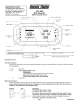
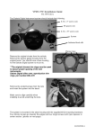
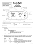
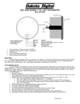
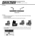
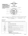
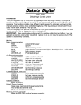
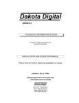
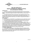
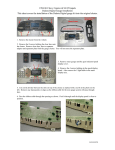
INSTALLATION AND OPERATION MANUAL
FOR
MCH-GPS17
GPS Compass and Ambient Temperature Gauge
KIT INCLUDES:
MCH-GPS17 GAUGE (x1)
MANUAL (x1)
SWITCH (x1)
NUTS (x3)
WIRE TIES (x6)
GAUGE FEATURES:
1
+12V
2
TEMP
SENSOR
3
4
FRONT
1.
2.
3.
4.
5.
6.
Signal indicator
Temperature reading
Heading reading
Message center
Switch connector
Gauge connector
6
REAR
GND
shows the strength of the received GPS signal
displays the temperature read from the sensor
displays the direction the gauge is moving in
can be set to display altimeter, clock or toggle between both readings
location to connect switch for use in gauge setup
location to connect stock gauge harness for gauge power and temp sensor
1
MAN # 650466
INSTALLATION:
Remove the outer fairing and the factory Air Temp gauge. This will vary by model; please follow the service manual to
expose the wiring and gauges. Don’t be alarmed by the amount of wires behind the fairing, this is a direct plug in kit and
these detailed instructions will guide you through installation.
With the Air Temp gauge removed; slide the push button harness through the fairing at the top opening of the
mounting basket and bring the factory 3-pin connector through the fairing at the bottom opening of the mounting
basket. The top and bottom openings are shown with arrows in the picture.
Connect the factory 3-pin connector and the
switch harness to the LCD compass gauge.
With the switch harness connector at the top, slide the gauge into the fairing with the two studs sliding through the holes
of the stock mounting basket. Use the provided nuts to secure the gauge to the mounting basket. One extra nut is
provided in case one is lost.
Use the provided zip ties to secure the switch to your desired location. You shouldn’t need to access the switch after
going through the operation and setup of the LCD compass, so you can secure the switch up inside the fairing or you can
secure the switch making it accessible under the fairing after reassembly if you want to change the backlighting or
settings later on.
2
MAN # 650466
OPERATION:
HOW IT WORKS:
The MCH-GPS17 uses the same GPS (Global Positioning System) signals that many common navigation systems use to
determine location in the world. This location data is used to determine your motorcycle’s direction of travel. Altimeter
(height above sea-level) and time data is also available from these signals and either or both can be displayed on the
MCH-GPS17.
To function properly, the GPS receiver in the gauge must have a clear view of the satellites in the sky to receive the
correct signals. This view can be blocked if the gauge is in a building, or parking garage, or in underground tunnels. Even
going under very wide overpasses can have an effect on the signal strength.
The gauge’s heading (N, NW, E etc.) is determined by the actual direction of the MOVEMENT of the gauge itself. This is
different from a conventional magnetic compass which uses the earth’s magnetic field to determine direction. Using GPS
signals for compass heading has several benefits over the magnetic method:
First, the orientation of the gauge is not critical to get a correct heading reading. The GPS compass will read correctly
even if it is mounted at an angle to the ground or the bike itself, which can often be the case in a motorcycle.
Second, the GPS compass will not be affected by the bending of the magnetic field due to close by metallic objects
(like the handle bars or motorcycle frame) or other magnetic fields from wires or speakers.
Third, the GPS compass will not need to be calibrated after it is installed, which is often the case for a magnetic
compass.
It is important to note however that the GPS compass MUST BE MOVING in order to get an accurate direction reading. If
the gauge is at a standstill, it will display the last direction calculated when it was moving, which may or may not be the
direction the vehicle is now pointed. Once the gauge is again moving, a new direction can be calculated and displayed.
POWERING UP:
When the gauge is powered on, it must first locate the satellites and determine its location. This can take some time,
especially if it has been a while since the gauge was last powered up. It can take up to a full minute depending on the
current position of the satellites and last power on time.
While the gauge is locating, the heading section of the gauge will be blank and the lower message center will read
“LOCATING…” until a GPS location is determined. Riding while the gauge is in this state will not have any negative effect
on the gauge or its location process.
Once the gauge has located enough satellites, the heading will be displayed in the heading section and the message
center will begin to show the selected data (Altimeter or clock).
TEMPERATURE DISPLAY:
The upper portion of the display shows the reading from the stock temperature sensor from the bike. This readout can be
set to display in either Fahrenheit or Celsius through the “TEMP UNIT” option in the setup menu.
MESSAGE DISPLAY:
There are three options for the lower message display area: Altimeter, Time, or toggle between Altimeter and Time. This
is set using the “DISPLAY” option in the setup menu.
When set to display altimeter (height above sea level) the reading can be in either meters or feet (see “ALTIM UNIT”
option in setup)
When set to display time, the hour offset from UTC (Coordinated Universal Time) must be set for your specific location
and daylight savings in order to read correctly. The offset can be set in the “SET HOUR” option in setup.
When set to toggle between altimeter and time, the screen will switch every 2 seconds to display either the time or the
altimeter. This allows both readings to be available to view over time.
3
MAN # 650466
SETUP:
ENTERING SETUP:
1. The supplied switch must be connected to the switch connector on the back of the gauge.
2. Press and hold the switch while turning on the motorcycle key, powering up the gauge.
3. The screen will display “SETUP”. Release the switch to enter the setup menu.
USING SETUP MENU:
4.
5.
6.
7.
8.
Press and release the switch to move through the different setup menu options.
To select a menu option, press and hold the switch until the screen changes.
Press and release the switch to change the setting if desired (unless noted otherwise below).
Press and hold the switch to save the setting (unless noted otherwise below).
Display will show “DONE”. Release the switch to return to main menu.
EXITING SETUP:
To exit the setup menu, select “EXIT” from the main setup menu. Alternatively, the key may be turned off while in
the main setup menu.
NOTE: If the key is turned off while in a menu option changing settings, the displayed setting will not be saved.
The setting that was previously stored will be used on next power up.
SETUP MENU:
CONTRAST
Allows adjustment to the LCD screen contrast
(See “SETTING CONTRAST” below for switch function)
SET HOUR
Sets hour offset from UTC (Coordinated Universal Time) from GPS
FORMAT
selects between 12hr (2:34 PM) and 24hr (14:34) time formats
UTC-11hrs to UTC+12hrs
sets hour offset from UTC for your local time zone (will need to be adjusted
when time goes from daylight savings time to standard time or vice versa).
DISPLAY
ALTIMETER
CLOCK
ALT / CLK TOGGLED
Sets function of lower information display area
will display only the altimeter (height above sea level) in lower information section
will display only the clock in lower information screen
will toggle between altimeter and clock every 2 seconds
COLOR
Selects backlight color of gauge from 8 colors
STOCK
Color designed to appear like the color of lighting in stock gauges
GREEN – CYAN – BLUE – MAGENTA – WHITE – RED – YELLOW
additional colors
BRIGHTNESS
0-31
Sets the backlight brightness
Backlight brightness. 0 dimmest, 31 is brightest.
TEMP UNIT
F
C
Sets the unit used to display temperature reading
temperature is displayed in Fahrenheit
temperature is displayed in Celsius
ALTIM UNIT
FT
M
Sets the unit used to display altimeter reading
altimeter reading is displayed in feet
altimeter reading is displayed in meters
INFO
Displays system information (may be needed for troubleshooting or tech support)
Press and release switch to change screens, Press and hold to return to main menu.
Available data: signal strength readings, speed in MPH, firmware version, and time.
RESET
Resets all settings back to the factory presets
RESET ALL SETTINGS Y/N
asks you to verify selection of reset
EXIT
Leaves the setup menu
4
MAN # 650466
SETTING CONTRAST
Depending on the location of the gauge and the angle the gauge is viewed from, the contrast setting may need to
be adjusted to make the gauge more readable. The following steps allow the contrast to be set:
1. Enter setup menu as described in setup and select “CONTRAST” from the menu.
2. Release switch
3. Press and hold switch to INCREASE the contrast.
4. Release switch to stop adjusting.
5. If needed, press and hold the switch again to REDUCE the contrast.
6. Release switch to stop adjusting.
7. Repeat steps 3 through 6 as needed until desired contrast level is set.
8. Do not press the switch for 5 seconds to save the new contrast setting (dots fill bottom of screen to
show remaining wait time).
9. Display will show “DONE” when setting is saved.
10. Press and release the switch to return to the setup menu.
SET HOUR OFFSET
If the message display is set to show time, the hour offset must be set to show correct time. Time data is received
from the GPS signals in the form of UTC (Coordinated Universal Time) which will need an hour offset for the time
zone you are in. This offset will also need to be adjusted when the local time changes from standard time to
daylight savings time and back again. The chart below is provided to show the offset needed for several time
zones. If you are unsure what time zone you are in or your time zone is not listed in the chart, the adjusted time is
also displayed in this setup option. Simply match the displayed time to the local time.
TIME ZONE HOUR OFFSET CHART
TIME ZONE
STANDARD TIME
(winter)
DAYLIGHT SAVINGS TIME
(summer)
EASTERN
CENTRAL
UTC-05 HRS
UTC-06 HRS
UTC-04 HRS
UTC-05 HRS
MOUNTAIN
PACIFIC
ALASKA
HAWAII
UTC-07 HRS
UTC-08 HRS
UTC-09 HRS
UTC-10 HRS
UTC-06 HRS
UTC-07 HRS
UTC-08 HRS
NOT OBSERVED
Gauge Specifications
SUPPLY
Voltage Range
Current draw
8 to 18 V
< 120 mA
SERVICE AND REPAIR
DAKOTA DIGITAL offers complete service and repair of its product line. In addition, technical consultation is available to help you work through any questions or
problems you may be having installing one of our products. Please read through the Troubleshooting Guide. There, you will find the solution to most problems.
Should you ever need to send the unit back for repairs, please call our technical support line, (605) 332-6513, to request a Return Merchandise Authorization
number. Package the product in a good quality box along with plenty of packing material. Ship the product by UPS or insured Parcel Post. Be sure to include the RMA
number on the package, and include a complete description of the problem with RMA number, your full name and address (street address preferred), and a telephone number
where you can be reached during the day. Any returns for warranty work must include a copy of the dated sales receipt from your place of purchase. Send no money. We will
bill you after repair.
Dakota Digital 24 Month Warranty
DAKOTA DIGITAL warrants to the ORIGINAL PURCHASER of this product that should it, under normal use and condition, be proven defective in material or
workmanship within 24 MONTHS FROM THE DATE OF PURCHASE, such defect(s) will be repaired or replaced at Dakota Digital’s option.
This warranty does not cover nor extend to damage to the vehicle’s systems, and does not cover removal or reinstallation of the product. This Warranty does not
apply to any product or part thereof which in the opinion of the Company has been damaged through alteration, improper installation, mishandling, misuse, neglect, or
accident.
This Warranty is in lieu of all other expressed warranties or liabilities. Any implied warranties, including any implied warranty of merchantability, shall be limited to
the duration of this written warranty. Any action for breach of any warranty hereunder, including any implied warranty of merchantability, must be brought within a period of 24
months from date of original purchase. No person or representative is authorized to assume, for Dakota Digital, any liability other than expressed herein in connection with
the sale of this product.
5
MAN # 650466
TROUBLESHOOTING:
Problem
Screen reads “INTERNAL
BATTERY VOLTAGE IS
LOW” after bike storage.
Screen reads “INTERNAL
BATTERY VOLTAGE IS
LOW” even after several
longer rides.
Screen reads “LOCATING…”
for a long time after power
up.
Possible cause
Internal battery has discharged
over long term off season storage
of the motorcycle.
Internal battery needs
replacement or service.
Solution
Battery should recharge during the time the key
is on over the first few rides of the season.
System is attempting to
determine its position from the
GPS satellites.
Locating may take longer if it has been a long
time since the key was last on or the bike has
been moved a good distance (such as on a
trailer) since the key was last turned off.
Locating will also take longer if the internal
battery voltage is low.
Too few or no GPS satellites are
in view.
GPS signals typically can be blocked if the bike
is in a building, parking garage, or if it is parked
very close to large structures. Move the bike
into a more open location.
Gauge mounting location
interfering with signal.
Gauge needs service.
Gauge can not be enclosed in metal casing as
this can block the GPS signals.
Contact Dakota Digital technical support for an
RMA number to return gauge for service.
Temp sensor wire may be broken
or disconnected.
Temp sensor wire is shorted to
ground.
Hour offset from UTC has not
been set.
Check the temp sensor wire for connection.
Check the temp sensor ground connection.
Check temp sensor wires for pinched areas,
rubbed off or missing insulation.
Use the setup menu to set the hour offset for
your local time zone.
Time has changed from daylight
savings time to standard time or
vice versa.
Use the setup menu to adjust the hour offset
for the current time. (Due to many varying rules
of the observance of DST in different areas,
this adjustment can not be done automatically.)
See setup for contrast adjustment.
OR
Signal indicator shows few or
no bars.
Screen reads “LOCATING”
with no dots following it at
power up.
Temperature section of
screen displays “EE”.
Temperature section of
screen displays “--“.
Clock time (if displayed) is
not correct.
Display is difficult to read /
image blends together.
Display is too dark to read at
night.
LCD contrast setting needs to be
adjusted.
LCD backlight setting needs to
be adjusted.
The internal battery is not user serviceable.
Contact Dakota Digital for an RMA number to
have the battery serviced.
See setup for backlight adjustment.
4510 W. 61st St. North
Phone (605) 332-6513
Sioux Falls, SD 57107
Fax (605) 339-4106
www.dakotadigital.com
[email protected] Copyright 2013 – Dakota Digital, Inc.
6
MAN # 650466