1
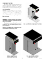
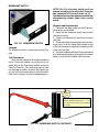
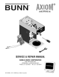
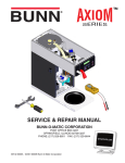
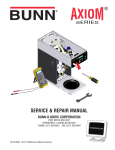
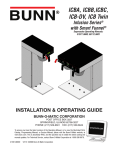
ITB/ITCB/HV
ICB/TWIN
Infusion Series®
SERVICE & REPAIR MANUAL
BUNN-O-MATIC CORPORATION
POST OFFICE BOX 3227
SPRINGFIELD, ILLINOIS 62708-3227
PHONE: (217) 529-6601 FAX: (217) 529-6644
42461.0000C 06/12 ©2010 Bunn-O-Matic Corporation
BUNN-O-MATIC COMMERCIAL PRODUCT WARRANTY
Bunn-O-Matic Corp. (“BUNN”) warrants equipment manufactured by it as follows:
1) Airpots, thermal carafes, decanters, GPR servers, iced tea/coffee dispensers, MCP/MCA pod brewers thermal servers
and Thermofresh servers (mechanical and digital)- 1 year parts and 1 year labor.
2) All other equipment - 2 years parts and 1 year labor plus added warranties as specified below:
a) Electronic circuit and/or control boards - parts and labor for 3 years.
b) Compressors on refrigeration equipment - 5 years parts and 1 year labor.
c) Grinding burrs on coffee grinding equipment to grind coffee to meet original factory screen sieve analysis - parts
and labor for 4 years or 40,000 pounds of coffee, whichever comes first.
These warranty periods run from the date of installation BUNN warrants that the equipment manufactured by it will be
commercially free of defects in material and workmanship existing at the time of manufacture and appearing within the
applicable warranty period. This warranty does not apply to any equipment, component or part that was not manufactured
by BUNN or that, in BUNN’s judgment, has been affected by misuse, neglect, alteration, improper installation or operation,
improper maintenance or repair, non periodic cleaning and descaling, equipment failures related to poor water quality,
damage or casualty. In addition, the warranty does not apply to replacement of items subject to normal use including but
not limited to user replaceable parts such as seals and gaskets. This warranty is conditioned on the Buyer 1) giving BUNN
prompt notice of any claim to be made under this warranty by telephone at (217) 529-6601 or by writing to Post Office
Box 3227, Springfield, Illinois 62708-3227; 2) if requested by BUNN, shipping the defective equipment prepaid to an
authorized BUNN service location; and 3) receiving prior authorization from BUNN that the defective equipment is under
warranty.
THE FOREGOING WARRANTY IS EXCLUSIVE AND IS IN LIEU OF ANY OTHER WARRANTY, WRITTEN OR ORAL, EXPRESS OR IMPLIED, INCLUDING, BUT NOT LIMITED TO, ANY IMPLIED WARRANTY OF EITHER MERCHANTABILITY
OR FITNESS FOR A PARTICULAR PURPOSE. The agents, dealers or employees of BUNN are not authorized to make
modifications to this warranty or to make additional warranties that are binding on BUNN. Accordingly, statements by such
individuals, whether oral or written, do not constitute warranties and should not be relied upon.
If BUNN determines in its sole discretion that the equipment does not conform to the warranty, BUNN, at its exclusive option while the equipment is under warranty, shall either 1) provide at no charge replacement parts and/or labor (during the
applicable parts and labor warranty periods specified above) to repair the defective components, provided that this repair
is done by a BUNN Authorized Service Representative; or 2) shall replace the equipment or refund the purchase price for
the equipment.
THE BUYER’S REMEDY AGAINST BUNN FOR THE BREACH OF ANY OBLIGATION ARISING OUT OF THE SALE OF THIS
EQUIPMENT, WHETHER DERIVED FROM WARRANTY OR OTHERWISE, SHALL BE LIMITED, AT BUNN’S SOLE OPTION
AS SPECIFIED HEREIN, TO REPAIR, REPLACEMENT OR REFUND.
In no event shall BUNN be liable for any other damage or loss, including, but not limited to, lost profits, lost sales, loss of
use of equipment, claims of Buyer’s customers, cost of capital, cost of down time, cost of substitute equipment, facilities
or services, or any other special, incidental or consequential damages.
392, AutoPOD, AXIOM, BrewLOGIC, BrewMETER, Brew Better Not Bitter, BrewWISE, BrewWIZARD, BUNN Espress, BUNN
Family Gourmet, BUNN Gourmet, BUNN Pour-O-Matic, BUNN, BUNN with the stylized red line, BUNNlink, Bunn-OMatic,
Bunn-O-Matic, BUNNserve, BUNNSERVE with the stylized wrench design, Cool Froth, DBC, Dr. Brew stylized Dr. design,
Dual, Easy Pour, EasyClear, EasyGard, FlavorGard, Gourmet Ice, Gourmet Juice, High Intensity, iMIX, Infusion Series, Intellisteam, My Café, Phase Brew, PowerLogic, Quality Beverage Equipment Worldwide, Respect Earth, Respect Earth with
the stylized leaf and coffee cherry design, Safety-Fresh, savemycoffee.com, Scale-Pro, Silver Series, Single, Smart Funnel,
Smart Hopper, SmartWAVE, Soft Heat, SplashGard, The Mark of Quality in Beverage Equipment Worldwide, ThermoFresh,
Titan, trifecta, Velocity Brew, A Partner You Can Count On, Air Brew, Air Infusion, Beverage Bar Creator, Beverage Profit
Calculator, Brew better, not bitter., BUNNSource, Coffee At Its Best, Cyclonic Heating System, Daypart, Digital Brewer
Control, Nothing Brews Like a BUNN, Pouring Profits, Signature Series, Tea At Its Best, The Horizontal Red Line, Ultra are
either trademarks or registered trademarks of Bunn-O-Matic Corporation.
2
42461 030912
INTRODUCTION
This equipment will brew a half-gallon batch of coffee into an awaiting dispenser. It can be easily
configured for 120V 15 amp, 120/208V 20 amp or 120/240V 20 amp. The brewer may have a hot water
faucet for allied beverage use. It is only for indoor use on a sturdy counter or shelf.
CONTENTS
Warranty..............................................................................................................2
Contents...............................................................................................................3
Troubleshooting...................................................................................................4
Diagnostic Displays..............................................................................................9
Access...............................................................................................................10
Control Board.....................................................................................................11
Membrane Switch..............................................................................................12
Brew Valves (Early)............................................................................................13
Brew Valves (Current)........................................................................................14
Refill Valves.......................................................................................................15
Tank Heaters......................................................................................................17
Limit Thermostat................................................................................................18
Temperature Probe............................................................................................19
DV Selector Switch............................................................................................21
On/Off Switch.....................................................................................................22
Schematic Wiring Diagrams...............................................................................23
3
42461 081310
TROUBLESHOOTING
A troubleshooting guide is provided to suggest probable causes and remedies for the most likely problems
encountered. If the problem remains after exhausting the troubleshooting steps, contact the Bunn-O-Matic
Technical Service Department.
• Inspection, testing, and repair of electrical equipment should be performed only by qualified service personnel.
• All electronic components have ac line voltage and some have low voltage dc potential on their terminals. Shorting of terminals or the application of external voltages may result in board failure.
• Intermittent operation of electronic circuit boards is unlikely. Board failure will normally be permanent. If
an intermittent condition is encountered, the cause will likely be a switch contact or a loose connection at a
terminal or crimp.
• Solenoid removal requires interrupting the water supply to the valve. Damage may result if solenoids are
energized for more than ten minutes without a supply of water.
• The use of two wrenches is recommended whenever plumbing fittings are tightened or loosened. This will
help to avoid twists and kinks in the tubing.
• Make certain that all plumbing connections are sealed and electrical connections tight and isolated.
• This brewer is heated at all times. Keep away from combustibles.
WARNING
•
Exercise extreme caution when servicing electrical equipment.
•
Unplug the brewer when servicing, except when electrical tests are specified.
•
Follow recommended service procedures.
•
Replace all protective shields or safety notices.
Before troubleshooting this brewer, check for the following:
Control Boards
1. Make sure ribbon cable is properly attached to the control board (ALL PINS INSERTED INTO PLUG).
2. Make sure there is a nylon insulating washer under each screw head that holds the control board to the
plastic front end cap. This is important for proper operation.
3. Make sure before servicing brewer that voltage is present at control board.
4. Press any warmer switch or observe if any indicator lights are glowing on the control panel. If so, proceed
with testing. If not, check for voltage across pins 1 & 2 of the ten pin J1 connector (black and white wires).
If voltage is present, replace the control board. If voltage is not present, check wiring and voltage across
terminal block (black and white). Correct the problem and retest before proceeding with testing.
NOTE: In the event of board replacement, technician will need to re-program customer's settings and/or recipes,
as well as re-calibrate the temperature probe in program level 3 and re-enter the serial number in level 4.
4
42461 081310
TROUBLESHOOTING (cont.)
REFILL CIRCUIT
PROBLEM
PROBABLE CAUSE
REMEDY
Will not refill
1. Power off to brewer
Press ENABLE BREW switch on
control panel to determine if power
is ON.
2. Water shut off
Make sure water is ON.
3. Error Message
Brewer has shut down due to malfunction (See Diagnostic Section in
this manual).
4.ON/OFF Switch
(If equipped)
Make sure ON/OFF Switch is "ON"
and indicator is lit.
5. Lime build up on Probe(s)
Remove the Level Probe(s) and
check for lime deposit on tip. Clean
and reinstall.
6. Refill Valve or Control Board
Check valve.
1. Lime build up on probe
Remove Level Probe and check
for lime deposits on tip. Clean and
reinstall.
2. Water Level Sensing System
Replace control board
Refill does not shut off
Power "ON"
3. Refill valve or control board
Refill does not shut off
Power "OFF"
Check valve.
Clean or replace valve as needed.
1. Refill valve
5
42461 081310
TROUBLESHOOTING (cont.)
HEATING CIRCUIT
PROBLEM
PROBABLE CAUSE
REMEDY
Water does not heat to proper
temperature
1. Display's error message
Brewer has shut down due to malfunction. See Diagnostics.
2. Water not touching main (short)
level probe
Remove level probe and grommet.
Look into hole on tank lid. Water
must be within approximately one
inch from top of tank.
3. Water Level Probe Sensing
System
Check refill circuit. Heaters will not
turn on if water is not grounding
level probe.
4. Temperature Probe
Check/replace
5. Limit Thermostat or TCO
Check/replace
6. Tank Heater
Check/replace
1. Lime build up on temperature
probe, tank or tank heater
Inspect probe and tank assembly
for excessive lime deposits. Delime
as required.
2. Temperature Probe
Check/replace
3. Control Board
Check/replace
1. Plumbing lines
Plumbing lines should not rest on
the counter top.
2. Water supply
The brewer must be connected to
a cold water supply.
3. Lime build up
Remove the tank lid and clean inside of tank with a deliming agent,
if necessary.
IMPORTANT: Make sure no temperature tests are taken before
the display reads ready. Tank temperature must be stabilized before
readings are taken.
Spitting or excessive steaming
(cont.)
Brewer is making unusual noises
6
42461 081310
TROUBLESHOOTING (cont.)
BREWING CIRCUIT
PROBLEM
Brew cycle will not start
PROBABLE CAUSE
1. Display's error message
REMEDY
Brewer has shut down due to malfunction. See Diagnostics.
2. No water
Water lines and valves to the brewer
must be open.
3. No power or incorrect voltage to
the brewer
Check for voltage across the terminals at the terminal block.
4. ON/OFF switch not in the "ON"
position
The indicator lamp must be lit
5. Low water temperature (Brew
lockout is enabled)
Allow brewer to heat until ready, or
disable the brew lockout feature.
6. Water not touching refill probe
inside tank
7. Membrane Switch
Check/replace
8. Dispense valve
Check/replace
Check/replace
9. Control board
Consistently low beverage level in
the dispenser or beverage overflows
dispenser
Water must be in contact with refill
probe before brew cycle will start.
1. Brew volume
NOTE: Volume adjustments must be
made with sprayhead installed.
Inspect the dispense valve and
sprayhead for excessive lime deposits. Delime as required.
2. Lime build up
Remove dispense valve and clear
any obstructions. Rebuild or replace
valve if necessary. (See page 24)
3. Dispense Valve
Check/replace
7
42461 081310
TROUBLESHOOTING (cont.)
BREWING CIRCUIT (cont.)
PROBLEM
PROBABLE CAUSE
REMEDY
Dripping from sprayhead
1. Lime build up
Inspect the tank assembly for excessive lime deposits. Delime as
required.
2. Dispense valve
Check/replace
1. Sprayhead
A clean sprayhead must be used for
proper extraction.
2. Water temperature
Place an empty brew funnel on an
empty decanter beneath the sprayhead. Initiate brew cycle and check
the water temperature immediately
below the sprayhead with a thermometer. The reading must not be
less than 195°F (91°C). Adjust the
temperature setting to increase the
water temperature. Refer to Initial
Set-up instructions.
Weak beverage
3. Filter type
BUNN® paper filters must be used
for proper extraction.
4. Coffee grind
A fine drip or grind must be used
for proper extraction.
5. Funnel loading
Dry coffee grounds remain in the
funnel
1. Sprayhead
Make sure sprayhead is present and
holes are clear and unobstructed.
2. Funnel loading
Low beverage serving temperature
The BUNN® paper filter must be
centered in the funnel and the bed
of grounds leveled by shaking
gently.
1. Thermal server/airpot not preheated before brew cycle
8
The BUNN® paper filter must be
centered in the funnel and the bed
of grounds leveled by shaking
gently.
Preheat server
42461 081310
DIAGNOSTICS
MESSAGE
PROBABLE CAUSE
REMEDY
Temperature Too Low
1. Water temperature in the tank
does not meet the ready temperature.
A) Wait for the brewer to heat to
the proper temperature.
1. Tank Heater failure.
Replace or repair as needed
2. Control Board/Thermistor failure
Replace or repair as needed
1. Water shut off to brewer
Check water supply shut-off
2. Supply line too small or obstructed
Replace or repair as needed
3. Inlet Solenoid failure
Replace or repair as needed
4. Control Board Failure
Replace or repair as needed
5. ON/OFF switch is OFF
Turn switch ON
Temp Sensor Out Of Range, Check
For Bad Connections
1. Temperature Sensor Probe
open
Replace or repair as needed
Temp Sensor Out Of Range, Check
Wire For Shorts
1. Temperature Sensor Probe
wire(s) shorted
Replace or repair as needed
Heating Time Too Long
Fill Time Too Long
9
B) Disable the BREW LOCKOUT
function. Refer to programming
section for procedure.
42461 081310
COMPONENT ACCESS
This section provides procedures for testing and
replacing various major components used in this
brewer should service become necessary. Refer to
Troubleshooting for assistance in determining the
cause of any problem.
WARNING - Inspection, testing, and repair of electrical equipment should be performed only by qualified
service personnel. The brewer should be unplugged
when servicing, except when electrical tests are required and the test procedure specifically states to
plug in the brewer.
WARNING - Disconnect the brewer from the power
source before the removal of any panel or the replacement of any component.
All components are accessible by the removal of
the top cover, front access panel (ICB), or rear access
panel (ITCB & ITB).
FIG. 10-2 ITB/ITCB COMPONENT ACCESS
Refer to wiring diagrams at the back of this
manual when reconnecting wires.
FIG. 10-3 ICB/ITCB HV TWIN
COMPONENT ACCESS
FIG. 10-1 ICB/ITCB HV
COMPONENT ACCESS
10
42461 081310
CONTROL BOARD
Removal and Replacement:
1. Disconnect brewer from power source.
2. Disconnect the wires from the relay on the control
board.
3. Disconnect all of the connectors from the control
board.
4. Remove the two nuts securing the control board
to the hood.
5. Tilt the control board inward to clear the display
section.
6. Place the bottom edge of the new control board in
the cradle, tilt the board forward, and secure with
the two nuts to the hood.
7. Re-install connectors.
FIG. 11-1 CONTROL BOARD
Faceplate Removal and Replacement:
1. Disconnect brewer from power source.
2. Disconnect the ribbon cable from the control
board.
3. Models with faucet: Drain tank to below faucet
outlet fitting. Remove hose, nut and washer from
faucet. Remove faucet assembly.
4. Remove the four screws securing the face plate
to the hood.
5. Carefully pull the ribbon cable through the front
opening of the hood.
6. Installation is the reverse order.
Location:
The Control Board is located inside the top cover
behind the front face plate.
Test Procedures:
The test procedures for the control board will vary
depending upon the problems experienced by the
brewer. Refer to the Troubleshooting section which
is divided into three sections, Refill Circuit, Heating
Circuit, and Brewing Circuit.
Check for Power to board:
1. Insert one meter lead in J17-pin 9 and the other
lead in J17-pin 11 (TR-2 to TR-5 ITB only).
2. With the power connected to brewer, the voltage
reading to the board should be the line voltage
rated for that model.
If no voltage is present, check wiring to the
board. If voltage is present, and brewer does
not power on, go to step 3
3. Check for line voltage at J15-1 BLK to J15-2 WHI
(J14-1 to 2 ITB only)
If no voltage is present, replace the control
board. If voltage is present, go to step 4
4. Check for 12VAC at J15-4 to J15-2 Yellow wires
(J14-4 to J14-5 ITB only)
If no voltage is present, replace the transformer. If voltage is present, and brewer does
not power on, replace the control board.
FIG. 11-2 FACEPLATE REMOVAL
11
42461 081310
CONTROL BOARD-ICB TWIN/ITCB DV HV/ITCB TWIN HV TRIAC MAP
FIG. 12-1 TRIAC MAP
Triac:Load Component:
TH1/MOV4/BR2
Left Funnel Lock
TH2/MOV1
Refill solenoid
TH3/MOV3/BR3
Right Funnel Lock
TH4B/MOV2
Tank Heaters
TH5/MOV5
Left Brew Solenoid
TH6/MOV7
Right Brew Solenoid
TH7/MOV8
Left Bypass Solenoid
TH8/MOV6
Right Bypass Solenoid
Connector:
J17-13/J17-14
J17-5
J17-6/J17-7
Relay Terminal
J17-3
J17-2
J17-1
J17-10
12
42461 081310
CONTROL BOARD-ICB/ITCB TRIAC MAP
FIG. 13-1 TRIAC MAP
Triac:Load Component:
TH2/MOV1/BR2
(Optional) Funnel Lock (ICB)
TH4B/MOV2
Refill solenoid
TH6/MOV4
Brew Solenoid
TH7/MOV3
Tank Heater(s)
TH9/MOV5
Dilution or Bypass Solenoid
Connector:
J17-13/J17-14
J17-5
J17-3
Relay Terminal
J17-1
13
42461 081310
CONTROL BOARD-ITB TRIAC MAP
FIG. 14-1 TRIAC MAP
Triac:Load Component:
TH1/MOV3
Main or Left Dilution
TH2/MOV1
Refill solenoid
TH3/MOV2
Brew Solenoid
TH4/MOV4
Right Dilution
TH6/MOV6 Sweetner
TH7/MOV7
Tank Heater
Connector:
J10-1
J10-2
J10-3
J10-4
J10-5
TR1/TR6
14
42461 081310
MEMBRANE SWITCH
NOTE: Pin 22 is the static shield & will not
provide a reading to the other pins. There are
two commons in this circuit, pins 9 & 10.
Disconnect brewer from power source before
disconnecting ribbon cable from control
board.
Removal and Replacement:
1. Disconnect the ribbon cable from the 22-pin connector on the control board.
2. Gently peel the membrane switch from the front
face plate assembly.
4 Remove any adhesive that remains on the front
face plate.
5. Remove the adhesive backing from the new membrane switch. Insert the ribbon cable through the slot
in the front face plate and apply the membrane switch
to the front face plate.
6. Connect the ribbon cable to the 22-pin connector on
the control board making sure every pin on the control
board is inserted into the ribbon cable connector.
FIG. 15-1 MEMBRANE SWITCH
Location:
The Membrane Switch is located on the front face
plate.
Test Procedures:
There are two methods for testing the membrane
switch. The easiest method is to use the built in test
mode. Refer to the Programing Section for Service
Tools/Test Switches. If for some reason you can't get
into the program modes, or brewer won't power up,
you can test it with an ohmmeter or continuity tester.
Refer to the schematic to trace the appropriate pins.
Helpful
Hint
Wrap a thin paper clip around each meter
lead and extend past the tip by ¼" - ½". You
may need to sand off the clear coating on
some clips!
FIG. 15-2 MEMBRANE SWITCH CONTINUITY
15
42461 081310
BREW VALVE (EARLY MODELS) AND BYPASS VALVE ON ALL ICB's
observed, brew valve is defective. Replace valve and
test again to verify repair.
If voltage is not present as described, refer to Wiring Diagrams and check the brewer wiring harness.
Also check the control board and switch for proper
operation.
Removal and Replacement:
1. Disconnect the brewer from the power source.
2. Disconnect wires from the valve.
3. Drain enough water from the tank so the water
level is below the outlet.
4. Remove hoses from the valve.
5. Remove the two #8-32 nuts securing the valve to
the sprayhead panel.
6. Install new valve using the two #8-32 nuts.
7. Reconnect hoses to the valve and secure in place
with clamps.
FIG. 16-1 EARLY BREW VALVE
Location:
The brew valve is located inside the top cover behind
the front face plate.
Test Procedures:
1. Refer to the Programing Section for Service Tools/
Test Outputs/Brew Valve.
2. Be sure brew funnel & server are in place before
activating valve.
3. Check the valve for coil action. Turn on the valve
with the test mode. Listen carefully in the vicinity of
the brew valve for a click as the coil pulls the plunger
in.
If no sound is heard as described, proceed to
#4.
If the sound is heard as described, there may be
a blockage in the valve , hose, tank, or sprayhead.
Disconnect the brewer from the power source.
Remove the valve and inspect for blockage, and
de-lime all related areas.
4. Connect the voltmeter leads to the coil terminals.
Turn on the valve with the test mode.
The indication will be 2-3VAC off, 120VAC on. Set
the meter to DC volts. The indication should be 150160VDC when off, 0V when on. If the polarity of meter
leads are reversed, reading will indicate -150-160VDC.
(Double these readings for 240 volt coils)
FIG. 16-2 EXPLODED VIEW
Due to the internally rectified coil, do not
attempt to test this type of coil with an ohmmeter. The reading will be open or very high
resistance, depending on the polarity of your
meter leads.
If voltage is present as described, but no coil action is
16
42461 081310
BREW VALVE (LATE MODELS)
Diagrams and check the brewer wiring harness. Also
check the control board and membrane switch for
proper operation.
Removal and Replacement:
1. Disconnect the brewer from the power source.
2. Disconnect wires from the valve.
3. Drain enough water from the tank so the water
level is below the outlet.
4. Remove sprayhead and hose from the valve.
5. Remove the nut securing the valve to the sprayhead
panel.
6. Install new valve using the nut from step 5.
7. Reinstall sprayhead and hose to the valve and
secure in place with clamps.
FIG. 17-1 LATE MODEL BREW VALVE
Location:
The brew valve is located inside the top cover behind
the front face plate.
Test Procedures:
1. Refer to the Programing Section for Service Tools/
Test Outputs/Brew Valve.
2. Be sure brew funnel & server are in place before
activating valve.
3. Check the valve for coil action. Turn on the valve
with the test mode. Listen carefully in the vicinity of
the brew valve for a click as the coil pulls the plunger
in.
If no sound is heard as described, proceed to #4.
If the sound is heard as described, there may be a
blockage in the valve , hose, tank, or sprayhead. Disconnect the brewer from the power source. Remove
the valve and inspect for blockage, and de-lime all
related areas.
4. Connect the voltmeter leads to the coil terminals.
Turn on the valve with the test mode.
The indication will be 2-3VAC off, 120VAC on. Set
the meter to DC volts. The indication should be 150160VDC when off, 0V when on. If the polarity of meter
leads are reversed, reading will indicate -150-160VDC.
(Double these readings for 240 volt coils)
If voltage is present as described, but no coil action
is observed, valve is defective. Replace valve and test
again to verify repair.
If voltage is not present as described, refer to Wiring
FIG. 17-2 LATE MODEL BREW VALVE
Due to the internally rectified coil, do not attempt to
test this type of coil with an ohmmeter. The reading
will be open or very high resistance, depending
on the polarity of your meter leads.
17
42461 081310
REFILL VALVES
If resistance is not present as described,
replace the refill valve.
If resistance is present as described, check
for debris in the valve.
Removal and Replacement:
1. Remove both wires from the refill valve.
2. Verify that the white shutoff clamp between valve
and tank is squeezed shut.
3. Disconnect both water lines at the valve.
4. Remove the two screws securing the valve to the
component mounting bracket.
5. Using the two screws, install the new valve to the
component mounting bracket.
6. Securely fasten the water lines to the valve.
7. Refer to wiring diagrams when reconnecting the
wires.
8. Install access panels and covers and refer to Initial
Set-up for refill and operation.
FIG. 17-1 REFILL VALVES
Location:
The refill valve is located inside the front of the
brewer.
Test Procedures:
1. Enter programming level 2, scroll to "Service Tools"
then scroll to "Refill Valve".
2. Briefly activate the refill valve in the test mode.
With a voltmeter, check the voltage across the coil
wires.
3. The indication must be 120 volts ac for two wire 120
volt models and three wire 120/208 -240 volt models
or 230 volts ac for two wire 230 volt models.
If voltage is present, proceed to # 4.
If voltage is not present, refer to Wiring Diagrams and check main wiring harness. If harness checks ok, replace control board.
4. Check the refill valve for coil action. Briefly activate
the refill valve in the test mode and listen carefully near
the refill valve for a "clicking" sound as the magnetic
coil pulls the plunger in.
If the sound is heard as described and water
will not pass through the refill valve, there
may be a blockage in the water line before
the refill valve or, the solenoid valve may
require inspection for wear, and removal of
waterborne particles.
If the sound is not heard as described, proceed to # 5.
5. Disconnect the brewer from the power source. 6.
Check for resistance across the coil terminals (200
-2k depending on which coil is being checked).
Disassembly:
Bunn does not offer repair/rebuild kits for the refill
valves, but some disassembly may be accomplished
on the early style valves in the event they may need to
be cleaned out. Disassembly is not recommended on
the newer style, as damage to the valve could occur.
Refer to next page for exploded views.
18
42461 081310
REFILL VALVES
EARLY ICB
CURRENT ICB & & ITB
Flow control used
on dual dilution
models only
SCREEN
EARLY ITCB
STRAINER
CURRENT ITCB & ITB-DD
SCREEN
STRAINER
19
42461 081310
TANK HEATERS
2268W
Large
Dia.
1425W
Small
Dia.
FIG. 20-2 DV TANK HEATERS
HEATER
RESISTANCE
1425W-120V
9.5-11.0
3500W-240V15.1-17.6
1680W-120V
7.9-9.2
1800W-120V
7.4-8.7
2268W-120V
5.9-6.9
3000W-208V12.9-15.1
3000W-240V17.9-20.7
3500W-200V10.5-12.2
TERMINAL TO SHEATH - INFINITE (OPEN)
FIG. 20-1 ICB TWIN TANK HEATERS
Location:
The tank heaters are located inside the tank and secured
to the tank bottom.
Test Procedures:
1. With a voltmeter, check voltage across the white
wire (120V Models) or red wire (120/208-240V
Models) from the terminal block and black wire
from the control board. Connect brewer to the
power source. The indication must be 120 volts
ac for two wire 120 volt models or 208-240 volts
ac for three wire 120/208-240 volt models (during
a heating cycle).
2. Disconnect the brewer from the power source.
NOTE- If any resistance is read between sheath and
either terminal, remove and inspect heater for cracks
in the sheath.
Removal and Replacement:
1. Remove the top cover and front access panel as
previously described.
2. Drain water from the tank.
3. Disconnect all the hoses from the tank.
4. Remove the temperature probe from the grommet
in the tank lid.
5. Remove the level probe from it's grommet.
6. Disconnect the green wire from the tank lid.
7. Disconnect the wires from tank heater terminals.
8. Remove the nuts securing the tank lid to the
tank.
9. Remove the hex nuts securing the tank heater to
the bottom of the tank. Remove tank heater(s) with
gaskets and discard.
10.Install new tank heater(s) with gaskets to the bottom of the tank and secure with two hex nuts.
11.Install tank lid and secure with nuts.
12.Reconnect the wires to tank heater terminals.
If voltage is present as described, proceed to #3.
If voltage is not present as described, refer to the Wiring Diagrams and check wiring harness.
3. Disconnect the wires from the tank heater terminals.
4. Check resistance value across tank heater terminals
and compare to chart.
If resistance is present as described, reconnect the
wires, the tank heater is ok.
If resistance is not present as described, replace the
tank heater.
20
42461 081310
LIMIT THERMOSTAT
FIG. 21-1 LIMIT THERMOSTAT
Location:
The limit thermostat is located on the tank lid (on the
front of the tank on twins).
FIG. 21-2 LIMIT THERMOSTATS
Test Procedures:
1. Disconnect the brewer from the power source and
allow to cool.
2. Disconnect the wires from the limit thermostat.
3. With an ohmmeter, check for continuity across
the limit thermostat terminals.
If continuity is present as described, the limit thermostat
is operating properly.
If continuity is not present as described, replace the
limit thermostat.
Removal and Replacement:
1. Remove the wires from limit thermostat terminals.
2. Carefully slide the limit thermostat out from under
the retaining clip and remove limit thermostat.
3. Carefully slide the new limit thermostat into the
retaining clip. Ensure the metal face has good contact
with tank.
21
42461 081310
TEMPERATURE PROBE
FIG. 22-1 TEMPERATURE PROBE
Location:
The temperature probe is inserted through the
tank lid assembly.
FIG. 22-2 TEMPERATURE PROBE
Test Procedures:
1. Disconnect the brewer from the power source.
2. With a DC voltmeter, check voltage across the two
wires at J13 (J3 on ITB) on control board (black
probe to black wire, red probe to white wire refer
to FIG 19-2). Connect the brewer to the power
source. The indication should be between 4vdc
(cool) to 1vdc at ready temperature.
3. Disconnect the brewer from the power source.
If voltage is present as described, circuit is working
correctly.
If voltage is not present as described, proceed to
#4.
4. Disconnect temperature probe from J9 on control
board. Check the resistance across the two terminals of the temperature probe. The indication
should be between 10.5K cool to 870 at ready
temperature.
If resistance is to specification, replace the control
board.
If resistance is not to specification, replace the temperature probe.
FIG. 22-3 TESTING TEMPERATURE PROBE
Removal and Replacement:
CONTINUED
22
42461 081310
TEMPERATURE PROBE
3. Press and hold the "Hidden" button until display
reads "CAL TEMPERATURE SENSOR?" "NO/YES"
4. Select "YES". The display should show something
similar to the screen below (FIG 20-2).
NOTE: Variables such as tank set temperature could
show different numbers than the example shown
here. Tank must be at it's ready temp before
calibrating.
5. Press the + (Control) button to increase or - (Digital) button to decrease temperature reading until
it matches the reading on the thermometer.
6. Exit program mode, remove thermometer, and
install vent fitting. Calibration is complete
Removal and Replacement:
1. Disconnect the brewer from the power source.
2. Disconnect the two pin connector from J9 on
control board.
3. Pull temperature probe out of it's grommet.
4. Install in reverse order.
Calibration:
1. Remove silicon vent fitting from tank lid.
2. Insert a digital temp probe through the exposed
vent hole in tank lid to the same depth as the factory temp probe. FIG 20-1.
200° CAL
(-)
DONE
200°
(+)
Adjust this
number
FIG. 23-2 CALIBRATION
FIG. 23-1 CALIBRATE TEMP PROBE
23
42461 081310
VOLTAGE SELECTOR SWITCH
Removal and Replacement:
1. Disconnect the brewer from the power source.
2. Disconnect the three wires from the selector
switch.
3. Remove the switch mounting nut from the under
side of component mounting bracket; remove
switch from bracket.
4. Install new switch in component mounting bracket
and secure with mounting nut.
FIG. 24-1 VOLTAGE SELECTOR SWITCH
Location:
The voltage selector switch is located on the
component mounting bracket on the base plate.
Test Procedure:
1. Disconnect the brewer from the power source.
2. Disconnect the wires from the selector switch. With
the selector switch in the 120V position, check for
continuity between the two right terminals of the
switch.
3. With the selector switch in the 120/208-240V
position, check for continuity between the two left
terminals.
FIG. 24-2 VOLTAGE SELECTOR
SWITCH TERMINALS
If continuity is not present as described, replace the
switch.
24
42461 081310
POWER SWITCH
Removal and Replacement:
1. Disconnect the brewer from the power source.
2. Disconnect the wires from the power switch.
3. Remove the switch mounting screws from the left
side of trunk.
4. Install new switch in trunk with the two 6-32 x ¼˝
mounting screws.
L2
L1
FIG. 25-1 POWER SWITCH (ICB SHOWN)
Location:
The power switch is located on the lower right
side of the trunk (ICB) or lower rear panel (ITCB).
FIG. 25-2 ROCKER SWITCH
Test Procedure:
1. Disconnect the brewer from the power source.
2. Disconnect the wires from the power switch. With
the switch in the ON position, check for continuity
between the upper and lower terminals on each
side of the switch.
There should be continuity between the two left terminals and between the two right terminals when ON,
no continuity when OFF.
FIG. 25-3 TOGGLE SWITCH
If continuity is not present as described, replace the
switch.
25
42461 081310
WHI
GRN
N
L2
RED
SCHEMATIC WIRING DIAGRAM
ITCB-DV & ITCB-C-DV
BLK
L1
MAIN ON/OFF SWITCH
(Late Models only)
BLK-18
BLK-14
LIMIT
THERMOSTAT
BLU-14
BLK-14
BLK
CONTROL P C BOARD
J1-1
J1-2
COM
N.O.
J17-1
VIO
SELECTOR
SWITCH
BLK-14
WHI-14
BLU-14
WHI/VIO
WHI/GRN
SOL
DISPENSE
SOL
DILUTION
WHI
WHI
WHI/BLU
WHI/BLU
RED-14
1800W
WHI/VIO
BLU-14
BLK-14
WHI/VIO
TANK HEATER
WHI/VIO-14
1680W
(1425W ITCB-C-DV ONLY)
FUNNEL SENSOR
1
3
WHI/GRN
J17-5
TANK HEATER
SOL
REFILL
WHI
BLK
J17-10
WHI
WHI
J17-14
J15-1
TRANSFORMER
10VA
J15-5
WHI
BLK
PNK
J13-1
J3-1
LEVEL
PROBE
GRN
t
J3-5
J3-8
1
CONTROL PANEL ASSY
J2-1
J2-5
J2-10
J2-15
BREW
A
PROG L
BREW
C
PROG R
HALF
FULL
BREW
B
ON/OFF
HALF
FULL
ON/OFF
J2-20
J2-22
22
J16-1
J16-5
J18-1
GRN
WHI
RED
BLK
STATIC
SHIELD
MEMORY
BOARD
(Early Models only)
120V AC 2 WIRE
120/208V AC 3 WIRE
120/240V AC 3 WIRE
SINGLE PHASE
J9-1
36460.0000D 02/07 ©2004 BUNN-O-MATIC CORPORATION
J9-7
26
42461 081310
SCHEMATIC WIRING DIAGRAM iTCBA, iTCBB
L2
GRN/YEL
L1
RED
BLK
BLK
RED
EMI
FILTER
RED
BLK
BLK
LIMIT
THERMOSTAT
BLU-14
BLK-14
RED
TANK HEATER
BLK-14
RED-14
RED-14
3500W
BLK
CONTROL P C BOARD
J1-1
J1-2
COM
N.O.
J17-1
VIO
FUNNEL SENSOR
1
3
WHI/VIO
BLU-14
BLK-14
WHI/VIO
WHI/VIO
WHI/GRN
J17-5
WHI/GRN
SOL
DISPENSE
SOL
DILUTION
WHI/BLU
WHI/BLU
RED
RED
SOL
REFILL
RED
BLK
J17-10
RED
RED
J17-14
J15-1
TRANSFORMER
10VA
J15-5
WHI
BLK
PNK
J13-1
J3-1
LEVEL
PROBE
GRN
t
J3-5
J3-8
1
CONTROL PANEL ASSY
J2-1
J2-5
J2-10
J2-15
BREW
A
PROG L
BREW
C
PROG R
HALF
FULL
BREW
B
ON/OFF
HALF
FULL
ON/OFF
J2-20
J2-22
22
J16-1
J16-5
J18-1
GRN
WHI
RED
BLK
STATIC
SHIELD
MEMORY
BOARD
(Early Models only)
200V AC 2 WIRE
230V AC 2 WIRE
SINGLE PHASE
J9-1
36460.0001C 08/09 ©2004 BUNN-O-MATIC CORPORATION
J9-7
27
42461 081310
WHI
GRN
N
L2
RED
SCHEMATIC WIRING DIAGRAM
ITCB-DV & ITCB-C-DV
BLK
L1
MAIN ON/OFF SWITCH
(Late Models only)
BLK-18
BLK-14
LIMIT
THERMOSTAT
BLU-14
BLK-14
(1425W ITCB-C-DV ONLY)
TANK HEATER
BLU-14
BLK-14
BLK
SELECTOR
SWITCH
1680W
CONTROL P C BOARD
J1-1
J1-2
COM
N.O.
J17-1
VIO
WHI/VIO-14
TANK HEATER
RED-14
1800W
FUNNEL SENSOR
1
3
BRN/WHI
WHI/VIO
BLU-14
BLK-14
SOL
WHI
BRN/WHI
WHI/VIO
WHI/VIO
WHI/GRN
J17-5
WHI-14
WHI/GRN
SOL
DISPENSE
SOL
DILUTION
WHI
WHI
WHI/BLU
WHI/BLU
OPTIONAL
SWEETENER
KIT
SOL
REFILL
WHI
BLK
J17-10
WHI
WHI
J17-14
J15-1
TRANSFORMER
10VA
J15-5
WHI
BLK
PNK
J13-1
J3-1
LEVEL
PROBE
GRN
t
J3-5
J3-8
1
CONTROL PANEL ASSY
J2-1
J2-5
J2-10
J2-15
BREW
A
PROG L
BREW
C
PROG R
HALF
FULL
BREW
B
ON/OFF
HALF
FULL
ON/OFF
J2-20
J2-22
22
J16-1
J16-5
J18-1
GRN
WHI
RED
BLK
STATIC
SHIELD
MEMORY
BOARD
(Early Models only)
120V AC 2 WIRE
120/208V AC 3 WIRE
120/240V AC 3 WIRE
SINGLE PHASE
J9-1
36460.0003A 06/08 ©2008 BUNN-O-MATIC CORPORATION
J9-7
28
42461 081310
WHI
Earth Ground
N
L2
RED
SCHEMATIC WIRING DIAGRAM
ITCB-DV & ITCB-C-DV
Chassis Ground
WITH FACTORY SWEETENER
BLK
L1
MAIN ON/OFF SWITCH
(Late Models only)
BLK-18
BLK-14
LIMIT
THERMOSTAT
BLU-14
BLK-14
BLK
CONTROL P C BOARD
J1-1
J1-2
COM
N.O.
J17-1
VIO
SELECTOR
SWITCH
BLK-14
WHI/VIO
WHI/GRN
SOL
RED-14
1800W
WHI/VIO
BLU-14
BLK-14
WHI/VIO
TANK HEATER
WHI/VIO-14
DISPENSE
SOL
DILUTION
BRN/WHI
SOL
WHI
WHI
WHI/BLU
WHI/BLU
BLK
J17-10
WHI-14
BLU-14
1680W
(1425W ITCB-C-DV ONLY)
FUNNEL SENSOR
1
3
WHI/GRN
J17-5
TANK HEATER
SOL
REFILL
SWEETENER
WHI
WHI
WHI
WHI
J17-14
J15-1
TRANSFORMER
10VA
J15-5
J13-1
J3-1
WHI
BLK
PNK
LEVEL
PROBE
LOW PRODUCT
DETECT SWITCH
GRN
t
J3-5
BLU
C
WHI/BLU
J3-8
1
NC
NO
CONTROL PANEL ASSY
J2-1
J2-5
J2-10
J2-15
BREW
A
PROG L
BREW
C
PROG R
HALF
FULL
BREW
B
ON/OFF
HALF
FULL
ON/OFF
J2-20
J2-22
22
STATIC
SHIELD
J16-1
J16-5
120V AC 2 WIRE
120/208V AC 3 WIRE
120/240V AC 3 WIRE
SINGLE PHASE
J18-1
J9-1
36460.0004A 10/08 ©2008 BUNN-O-MATIC CORPORATION
J9-7
29
42461 081310
WHI
GRN
N
L2
RED
BLK
L1
SCHEMATIC WIRING DIAGRAM ICB-DV
MAIN ON/OFF SWITCH
(Late Models only)
BLK-18
BLK-14
LIMIT
THERMOSTAT
BLU-14
BLK-14
BLK
CONTROL P C BOARD
J1-1
J1-2
COM
N.O.
J17-1
VIO
SELECTOR
SWITCH
BLK-14
WHI-14
BLU-14
WHI/VIO-14
1680W
FUNNEL SENSOR
1
3
TANK HEATER
RED-14
2268W
WHI/VIO
BLU-14
BLK-14
WHI/RED
WHI/RED
WHI/GRN
J17-5
TANK HEATER
WHI/GRN
SOL
DISPENSE
SOL
BYPASS
WHI
WHI/BLU
WHI/BLU
WHI
SOL
REFILL
WHI
BLK
J17-10
J17-14
WHI
WHI
BRN/BLK
BRN/WHI
SOL
FUNNEL LOCK
(Optional)
J15-1
TRANSFORMER
10VA
J15-5
WHI
BLK
PNK
J13-1
J3-1
LEVEL
PROBE
GRN
t
J3-5
J3-8
1
CONTROL PANEL ASSY
J2-1
J2-5
J2-10
J2-15
BREW
A
PROG L
BREW
C
PROG R
HALF
FULL
BREW
B
ON/OFF
HALF
FULL
ON/OFF
J2-20
J2-22
22
J16-1
J16-5
GRN
WHI
RED
BLK
STATIC
SHIELD
MEMORY
BOARD
(Early Models only)
120V AC 2 WIRE
120/208V AC 3 WIRE
120/240V AC 3 WIRE
SINGLE PHASE
J18-1
J9-1
37299.0000B 02/07 ©2004 BUNN-O-MATIC CORPORATION
J9-7
30
42461 081310
GRN
N
L2
WHI
BLK
L1
RED
SCHEMATIC WIRING DIAGRAM ICB TWIN
MAIN ON/OFF SWITCH
(Late Models only)
BLK-18
BLK-14
LIMIT
THERMOSTAT
BLU-14
BLU-14
LEFT
FUNNEL SENSOR
1
3
J20-1
VIO
J20-3
WHI/VIO
RIGHT
FUNNEL SENSOR
1
3
CONTROL P C BOARD
J21-1
YEL
J21-3
WHI/YEL
BLU-14
BLK-14
COM
N.O.
J17-1
J17-5
J17-10
J17-14
LIMIT
THERMOSTAT
BLU-14
BLU-14
SOL
SOL
TANK HEATER
TANK HEATER
LEFT
BYPASS
WHI
WHI
SOL
LEFT
DISPENSE
SOL
SOL
BLK
GRY
WHI
RED-14
RIGHT
DISPENSE
WHI/RED
ORN
WHI/GRN
WHI/BLU
BLU
BLU/BLK
RED-14
RIGHT
FUNNEL LOCK
(Optional)
SOL
RIGHT
BYPASS
WHI
REFILL
WHI
WHI
WHI
BRN/BLK
BRN/WHI
SOL
LEFT
FUNNEL LOCK
(Optional)
J15-1
TRANSFORMER
10VA
J15-5
J13-1
J3-1
WHI
BLK
PNK
LEVEL
PROBE
GRN
t
J3-5
CONTROL PANEL ASSY
J3-8
1
J2-1
J2-5
J2-10
LEFT
ON/OFF
J2-15
LEFT
FULL
LEFT
HALF
J2-20
J2-22
J16-1
J16-5
GRN
WHI
RED
BLK
RIGHT
ON/OFF
22
MEMORY
BOARD
RIGHT
FULL
RIGHT
HALF
(Early Models only)
120/208 OR 120/240
VOLTS AC
3 WIRE + GND
SINGLE PHASE
RIGHT
FULL
RIGHT
HALF
RIGHT
BREW
C
RIGHT
ON/OFF
RIGHT
BREW
B
RIGHT
PROG
PROG
“Control”
RIGHT
BREW
A
PROG
“Digital”
PROG
“Brewer”
LEFT
BREW
C
LEFT
PROG
LEFT
ON/OFF
LEFT
BREW
B
LEFT
FULL
LEFT
BREW
A
LEFT
HALF
STATIC
SHIELD
37299.0001C 02/07 ©2005 BUNN-O-MATIC CORPORATION
31
42461 081310
SCHEMATIC WIRING DIAGRAM iCBA, iCBB
L1
L2
GRN/YEL
RED
BLK
BLK
RED
EMI
FILTER
RED
BLK
BLK
LIMIT
THERMOSTAT
BLU-14
BLK-14
BLK-14
RED
TANK HEATER
RED-14
3500W
BLK
CONTROL P C BOARD
J1-1
J1-2
COM
N.O.
J17-1
VIO
FUNNEL SENSOR
1
3
WHI/VIO
BLU-14
BLK-14
WHI/RED
WHI/RED
WHI/GRN
J17-5
WHI/GRN
SOL
DISPENSE
SOL
BYPASS
WHI/BLU
WHI/BLU
RED
RED
SOL
REFILL
RED
BLK
J17-10
J17-14
RED
RED
BRN/BLK
BRN/WHI
SOL
FUNNEL LOCK
(Optional)
J15-1
TRANSFORMER
10VA
J15-5
WHI
BLK
PNK
J13-1
J3-1
LEVEL
PROBE
GRN
t
J3-5
J3-8
1
CONTROL PANEL ASSY
J2-1
J2-5
J2-10
J2-15
BREW
A
PROG L
BREW
C
PROG R
HALF
FULL
BREW
B
ON/OFF
HALF
FULL
ON/OFF
J2-20
J2-22
J16-1
J16-5
J18-1
GRN
WHI
RED
BLK
22
STATIC
SHIELD
MEMORY
BOARD
(Early Models only)
200V AC 2 WIRE
230V AC 2 WIRE
SINGLE PHASE
J9-1
J9-7
37299.0002B 08/09 ©2005 BUNN-O-MATIC CORPORATION
32
42461 081310
BRN
SCHEMATIC WIRING DIAGRAM ICB TWIN 230V
Chassis Ground
BLU
L1 L2
GRN/YEL
TERM
BLOCK
RED
BLK
GRN
EMI
FILTER
Chassis Ground
BLK-18
BLK-14
LIMIT
THERMOSTAT
BLU-14
BLU-14
LEFT
FUNNEL SENSOR
1
3
CONTROL P C BOARD
J20-1
VIO
J20-3
WHI/VIO
J21-1
YEL
J21-3
WHI/YEL
BLU-14
BLK-14
COM
N.O.
J17-1
J17-5
J17-10
J17-14
LIMIT
THERMOSTAT
BLU-14
BLU-14
RIGHT
FUNNEL SENSOR
1
3
SOL
SOL
TANK HEATER
TANK HEATER
RED
RED
SOL
LEFT
DISPENSE
SOL
SOL
BLK
GRY
RED
RED-14
LEFT
BYPASS
RIGHT
DISPENSE
WHI/RED
ORN
WHI/GRN
WHI/BLU
BLU
BLU/BLK
RED-14
RIGHT
FUNNEL LOCK
(Optional)
SOL
RIGHT
BYPASS
RED
REFILL
RED
RED
RED
BRN/BLK
BRN/WHI
SOL
LEFT
FUNNEL LOCK
(Optional)
J15-1
TRANSFORMER
10VA
J15-5
J13-1
J3-1
WHI
BLK
PNK
LEVEL
PROBE
GRN
t
J3-5
CONTROL PANEL ASSY
J3-8
1
J2-1
J2-5
J2-10
LEFT
ON/OFF
J2-15
LEFT
FULL
LEFT
HALF
J2-20
J2-22
J16-1
J16-5
RIGHT
ON/OFF
22
GRN
WHI
MEMORY
BOARD
RED
BLK
RIGHT
FULL
RIGHT
HALF
(Early Models only)
230 VOLTS AC
2 WIRE + GND
SINGLE PHASE
RIGHT
FULL
RIGHT
HALF
RIGHT
BREW
C
RIGHT
ON/OFF
RIGHT
BREW
B
RIGHT
PROG
PROG
“Control”
RIGHT
BREW
A
PROG
“Digital”
PROG
“Brewer”
LEFT
BREW
C
LEFT
PROG
LEFT
ON/OFF
LEFT
BREW
B
LEFT
FULL
LEFT
BREW
A
LEFT
HALF
STATIC
SHIELD
37299.0004A 12/08 ©2008 BUNN-O-MATIC CORPORATION
33
42461 081310
SCHEMATIC WIRING DIAGRAM ITB
SINGLE & DUAL DILUTION MODELS
AND MODELS w/OPTIONAL SWEETENER
L2
L1
WHI
BLK
WHI
TR-5 TR-2
CONTROL P C BOARD
TR-6
TR-1
J10-1
J10-5
TANK HEATER
RED
BLK
LIMIT THERMOSTAT
BLU/BLK
WHI/VIO
WHI/BLU
WHI/GRN
WHI/YEL
WHI/RED
DILUTION (MAIN or LEFT)
SOL REFILL
SOL
SOL
DISPENSE
SOL
RIGHT DILUTION (DUAL DILUTION MODELS ONLY)
OPTIONAL SWEETENER
SOL
WHI
WHI
WHI
WHI
WHI
J10-10
J14-1
J14-5
BLK
WHI
L-1
L-2
YEL
YEL
12VAC
TRANSFORMER
10VA
WHI
BLK
PNK
J3-1
TEMP
PROBE
LEVEL
PROBE
J2-1
ORN
WHI/ORN
J2-5
J2-8
1
2
3
OPTIONAL LOW PRODUCT
DETECT SWITCH
t
GRN
1. JUMPER FOR DUAL DILUTION MODELS ONLY
2. JUMPER FOR SWEETENER MODELS ONLY
3. JUMPER FOR DUAL DILUTION MODELS w/SWEETENER ONLY
MEMBRANE SWITCH ASSY
1
J15-1
J15-5
J15-10
J15-15
BREW
A
PROG L
BREW
C
PROG R
HALF
FULL
BREW
B
ON/OFF
HALF
FULL
ON/OFF
J15-20
J15-22
22
STATIC
SHIELD
120V AC 2 WIRE + GROUND
SINGLE PHASE
42377.0000B 12/09 ©2009 BUNN-O-MATIC CORPORATION
34
42461 081310
L1
Chassis Ground
WHI
BLK
Earth Ground
N
L2
RED
GRN/YEL
SCHEMATIC WIRING DIAGRAM ITCB-DV HV
MAIN ON/OFF SWITCH
BLK-18
BLK-14
LIMIT
THERMOSTAT
BLU-14
BLK-14
BLK
C
O
N
T
R
O
L
P
C
B
O
A
R
D
J1-1
J1-2
COM
N.O.
J17-1
VIO
BLK-14
J17-10
SELECTOR SWITCH
WHI-14
BLU-14
WHI/VIO-14
1680W
FUNNEL SENSOR
1
3
TANK HEATER
RED-14
2268W
COOLING FAN
WHI/VIO
BLU-14
BLK-14
BLK
WHI/RED
WHI/RED
WHI/GRN
J17-5
TANK HEATER
WHI/GRN
SOL
DISPENSE
MOT
WHI
BYPASS
SOL
WHI
REFILL
WHI/BLU
WHI/BLU
BLK
WHI/VIO
WHI
WHI/VIO
SOL
DILUTION
SOL
J17-14
J15-1
TRANSFORMER
10VA
J15-5
J13-1
J3-1
J3-5
J3-8
WHI
BLK
PNK
LEVEL
PROBE
GRN
t˚
COOLING FAN
THERMISTOR
1
t˚
CONTROL PANEL ASSY
J2-1
J2-5
J2-10
J2-15
BREW
A
PROG L
BREW
C
PROG R
HALF
FULL
BREW
B
ON/OFF
HALF
FULL
ON/OFF
J2-20
J2-22
STATIC
SHIELD
120V AC 2 WIRE
120/208V AC 3 WIRE
120/240V AC 3 WIRE
SINGLE PHASE
J18-1
J9-1
43828.0000A 11/10 ©2010 BUNN-O-MATIC CORPORATION
J9-7
35
White Strip-Tac Plus
WHI
WHI
WHI
WHI
N
L2
WHI
BLK
L1
RED
SCHEMATIC WIRING DIAGRAM ITCB HV TWIN
GRN
MAIN ON/OFF SWITCH
Earth Ground
Chassis Ground
LIMIT
THERMOSTAT
BLU-14
BLU-14
C
O
N
T
R
O
L
P
C
B
O
A
R
D
LEFT
FUNNEL SENSOR
1
3
J20-1
VIO
J20-3
WHI/VIO
RIGHT
FUNNEL SENSOR
1
3
J21-1
YEL
J21-3
WHI/YEL
BLU-14
BLK-14
COM
N.O.
J17-1
J17-5
J17-10
J17-14
K1
RED-14
LEFT
BYPASS
WHI
LEFT
DISPENSE
WHI
SOL
RIGHT
DILUTION
RELAY
BLK
GRY
WHI
SOL
REFILL
RIGHT
BYPASS
WHI
WHI
WHI
RED/BLK
BLU/BLK
K2
LEFT
DILUTION
RELAY
K2
BLK
WHI
K1
WHI/VIO
SOL
RIGHT
DILUTION
WHI
WHI
LEVEL
PROBE
GRN
t˚
CONTROL PANEL ASSY
1
J2-1
J2-5
J2-10
LEFT
ON/OFF
J2-15
LEFT
FULL
LEFT
HALF
J2-20
J2-22
RIGHT
ON/OFF
22
RIGHT
FULL
RIGHT
HALF
120/208 OR 120/240
VOLTS AC
3 WIRE + GND
SINGLE PHASE
LEFT
DILUTION
MOT
BLK
J3-8
SOL
BLK
WHI
BLK
t˚
COOLING FAN
THERMISTOR
WHI/YEL
COOLING FAN
J15-5
J3-5
TANK HEATER
RED-14
WHI
SOL
WHI/BLU
RED
BLK
PNK
TANK HEATER
RIGHT
DISPENSE
WHI/RED
ORN
WHI/GRN
TRANSFORMER
10VA
J3-1
SOL
SOL
J15-1
J13-1
LIMIT
THERMOSTAT
BLU-14
BLU-14
BLK-18
BLK-14
STATIC
SHIELD
44145.0000A 01/11 ©2011 BUNN-O-MATIC CORPORATION
36
White Strip-Tac Plus
RIGHT
FULL
RIGHT
HALF
RIGHT
BREW
C
RIGHT
ON/OFF
RIGHT
BREW
B
RIGHT
PROG
PROG
“Control”
RIGHT
BREW
A
PROG
“Digital”
PROG
“Brewer”
LEFT
BREW
C
LEFT
PROG
LEFT
ON/OFF
LEFT
BREW
B
LEFT
FULL
LEFT
BREW
A
LEFT
HALF
37