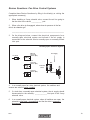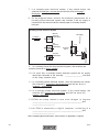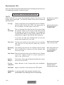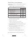
1
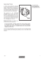
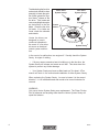
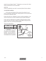
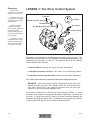
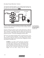
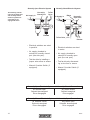
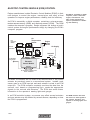
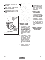
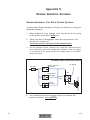
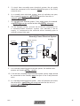
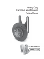
Heavy-Duty Fan Drive Maintenance Training Manual Table of Contents INTRODUCTION ................................................................................................................................ 4 LESSON 1: Fan Drive Operation ...................................................................................................... 5 LESSON 2: Heavy Duty Fan Drives .................................................................................................. 6 LESSON 3: Fan Drive Control System ............................................................................................ 10 REVIEW QUESTIONS: Fan Drive Control Systems .......................................................................... 19 LAB ACTIVITY: Fan Drive Components ......................................................................................... 21 LESSON 4: Preventive Maintenance (PM) ..................................................................................... 23 REVIEW QUESTIONS: Preventive Maintenance ............................................................................... 25 LESSON 5: Horton Fan Drive Components .................................................................................... 27 LESSON 6: Corrective Maintenance ............................................................................................... 30 REVIEW QUESTIONS: Corrective Maintenance ............................................................................... 34 FINAL TEST: Heavy Duty Fan Drive Maintenance .......................................................................... 35 APPENDIX A: Preventive Maintenance Check List 10,000 Miles [16,000 Km] .............................. 41 APPENDIX B: Preventive Maintenance Check List 25,000 Miles [40,000 Km] .............................. 42 APPENDIX C: Review Question Answers ....................................................................................... 44 22540 3 Introduction This student manual for the technical course, Heavy-Duty Fan Drive Maintenance, is designed to train heavy-duty diesel technicians how to perform preventive and corrective maintenance on Horton heavy-duty fan drives. This guide may be used in the classroom with an instructor or in a self-study mode. After completion of this course, take the Final Test at the end of this student manual. Mail your Final Test to the following address to receive a Certified Horton Technician toolbox sticker and a Horton Certificate of Achievement: Horton, Inc. 2565 Walnut St. Roseville, MN 55113, USA Phone: +1 (651) 361-6400 Toll-free: +1 (800)-621-1320 Fax: +1 (651) 361-6801 Web site: www.hortonww.com e-mail: [email protected] In accordance with Horton’s established policy of constant product improvement, the specifications contained in this manual are subject to change without notice and are based on the latest information available at the time of printing. 4 22540 LESSON 1: Fan Drive Operation Objectives • Recognize the purpose and advantages of a fan drive. Heavy-Duty Fan Drive Radiator When engaged, the fan drive activates the fan to cool the engine by pulling air through the radiator. Depending on the size and rotational speed of the fan blade, as much as 70-75 HP may be needed to run the fan. The fan drive engages only when needed resulting in additional horsepower for drive axles, less noise, and increased fuel economy. Due to these benefits, most new diesel powered trucks are equipped with a Horton on/off fan drive. 22540 An engaged fan drive pulls air through the radiator to cool the engine. 5 Objectives • Recognize the different models of Horton heavy-duty fan drives • Describe the Horton System Sentry® feature 9 “ [22.86 cm] single plate fan drives are painted gray. S and HT/S fan Drives are painted blue and may be upgraded by installing an Advantage Super Kit. S and HT/S Advantage fan drives are painted gun-metal blue. Advantage Reman fan drives are painted maroon. 6 LESSON 2: Heavy-Duty Fan Drives With more than 50 years of industry experience, Horton is a premier worldwide provider of the highest quality truck components. Horton supplies several different models of heavy-duty fan drives. 9 “ Single Plate The 9" [22.86 cm] single plate is an older style fan drive (rarely supplied on new trucks) with a larger air chamber than other Horton fan drives. Original S The S model fan drive has a drive plate that is 7.5 “ [ 19.05 cm] in diameter. An original S model fan drive has a smooth Piston Friction Disc (PFD), whereas the newer model with System Sentry® has three large bosses on the PFD. Original HT/S The HT/S model fan drive has a drive plate that is 9.5" [24.13 cm] in diameter. The original HT/S model fan drive has a smooth PFD while an Advantage model with System Sentry has three large bosses on the PFD. S and HT/S Advantage The S and HT/S Advantage are heavy duty fan drives, equipped to handle the frequent on/off cycles common in severe-duty trucking applications. Both fan drives include the System Sentry feature along with a plastic air cartridge and improved hub assembly. 22540 System Sentry® Feature The System Sentry feature disengages the fan drive when excessive temperatures occur. In 1994, Horton added the patented System Sentry® feature to the S and HT/S designs. System Sentry equipped fan drives have three large bosses on the PFD, one of which contains a System Sentry to protect the fan drive from overheating. The material in the left-hand threaded System Sentry has a melting point of approximately 600o F [316o C]. If a fan drive should start to slip and overheat, the fuse material will melt and open a passage to release the air pressure, disengaging the fan drive. System Sentry Replacement Fuses are available in all of the Horton fan drive repair kits. If a fuse has blown, carefully examine the entire cooling system to determine the cause. Replacing a fuse without examining the system may result in a repeated blown fuse and possible damage to the fan drive. The S and HT/S Advantage fan drives also utilize a new air cartridge design, improving reliability and reducing the possibility of an air leak inside the air chamber. 22540 7 Troubleshooting the fan drive and controls should be done promptly to locate the problem which caused the System Sentry® release of the fan drive. First locate and remove anything that may be an obstruction to the fan blade. Check the fan drive for leaks. If no leaks are found, check the solenoid and controls. Horton fan drives are designed to permit continued operation in the event of a fan drive air source or electrical control system malfunction. Allen Head System Sentry® Counter Balance Torx Head System Sentry® Piston Friction Disc System Sentry® In the event of a malfunction, turn engine off. Visually check the System Sentry for signs of melting. • If for any reason excessive heat is building up in the fan drive, the System Sentry will release and create an air leak. This shuts down the system to prevent any further damage. • Your System Sentry may have an Allen head or a Torx head. A Torx wrench will work in the removal and installation of either System Sentry. When replacing the System Sentry, be sure to loosen it in the correct direction. It is a left-hand thread and needs to be turned clockwise for removal. WARNING Only use a Horton System Sentry as a replacement. The Piston Friction Disc is balanced and anything other than the Horton System Sentry will upset the balance. 8 22540 Install the new System Sentry®. Troubleshoot and correct the failed system component(s) as soon as possible. CAUTION Failure to troubleshoot may result in reoccuring System Sentry releases. Lock Up Bolt Installation • In the event your System Sentry cannot be replaced or you cannot immediately troubleshoot the cooling system, the lock up bolts can be used as an alternative option. Horton fan drives are designed to permit continued operation in the event of a fan drive air source or electrical control system malfunction. In the event of a malfunction, turn engine off. Align two holes in Piston Friction Disc with two holes in sheave. Install grade 8 lockup bolts and tighten to 25 Ft. Lbs. [33.9 N•m] (See diagram). Cap Screw Specifications Size Grade 8, 5/16 - 18NC x 1” Qty 2 CAUTION The lock-up bolt installation procedure is only a temporary solution. The air source or electrical malfunction must be corrected as soon as possible. 22540 Tighten lockup bolts to 25 Ft. Lbs. [33.9 N•m] Torque 9 Objectives • describe the components of a fan drive electrical control system • determine the correct air inlet port for a normally open and normally closed solenoid valve • describe the basic operation of normally open, normally closed, and the electronic control module (ECM) and how they control the electrical control system LESSON 3: Fan Drive Control System To ignition Manual Override Switch Air Filter Thermal Switch A/C Refrigerant Pressure Switch Air Supply Solenoid Valve • determine if a truck’s fan drive electrical control system is wired normallyopen, normally-closed, or connected to an ECM Depicted is an illustration of an independent fan drive control system. The electrically controlled solenoid valve engages and disengages the fan drive by regulating its air pressure on and off. The electrical circuit to the solenoid valve contains three switches: • a thermal switch sensing the engine coolant temperature. • a refrigerant pressure switch in the truck’s air conditioning system. • an optional manual override switch located on the truck’s dashboard. Any of these three switches may activate the solenoid and engage the fan drive. EXAMPLE. When the engine coolant temperature rises above the thermal switch’s set point, the thermal switch will activate the solenoid valve, which will in turn send air pressure from the truck’s air reservoir to the fan drive and engage the fan. Most newer trucks have an Electronic Control Module (ECM) – a small computer that monitors and controls all engine operations, including the fan drive. If a truck uses an ECM, there is no direct connection between the sensors and fan drive solenoid valve. Information from sensors and switches is fed into the ECM which in turn controls the solenoid valve. 10 22540 Sensors Trucks not using an ECM usually have two sensors to automatically turn the fan on and off. First is the engine coolant thermal switch and second the air conditioning refrigerant pressure switch. The engine coolant thermal switch is mounted in the water jacket on the engine. • In a normally-open thermal switch, the electrical contacts are open when the temperature is below the set point and closed when the temperature is above the set point. • In a normally-closed thermal switch, the electrical contacts are closed when the temperature is below the set point and open when the temperature is above the set point. The refrigerant pressure switch is installed in the high pressure line of the cab’s air conditioning system. When the air conditioner is running, heat removed from the air is absorbed by the refrigerant (e.g., freon, R-12 and R-134a). As the refrigerant heats, pressure builds in the air conditioner high pressure line until the refrigerant pressure reaches the switch’s set point. The switch then sends a signal to the solenoid valve to engage the fan drive. The fan pulls air through the air conditioner condenser coils, which cools the condenser/refrigerant and reduces refrigerant pressure. Thermal switch reset point is usually 7oF [3.9oC] below the set point. Truck designers will typically specify a thermal switch with a set point 10-15o F [5.6-8.3o C] higher than the fully open temperature of the engine thermostat. Air conditioning refrigerant pressure switches are available as either normally-open or normally-closed. Air Filter To solenoid valve inlet port Truck Air in I N Air Filter Drain Valve 22540 Some trucks have an air filter in the supply line going into the solenoid valve. As shown, the Horton air filter connects directly to the solenoid valve inlet port. The air filter contains an element to remove dirt from the compressed air before it enters the solenoid valve. A drain valve at the bottom of the filter provides a check for excessive contaminants. Drain the truck’s air system prior to air filter removal. The filter is easily removed for cleaning by unscrewing the bowl from the bottom of the assembly, then unscrewing the filter element. 11 Solenoid Valve The solenoid valve is the heart of the fan drive control system, opening and closing to regulate the air flow to the fan drive. The solenoid valve is a 3way valve having two inlet and one outlet ports. Air pressure from the truck’s air system is fed into one of the inlet ports and the outlet port is connected to the fan drive. The valve has a 3/64" [1.19 mm] orifice to regulate the volume of air and ensure smooth engagement and disengagement of the fan drive. N.O. Inlet Port/ NC Exhaust Port N.C. Inlet Port/ N.O. Exhaust Port Air Outlet Port To Fan Drive Turning the solenoid electric current on and off causes a plunger inside the valve to move up and down. The plunger connects the valve outlet port to one of the two inlet ports: • the normally-open port when the electric current is off. • the normally-closed port when the electric current is on. Normal (as in normallyopen or normally-closed) refers to the state of the solenoid valve when it is relaxed or de-energized. EXAMPLE. Normal can be expressed as the state the solenoid valve would be in if it was completely disconnected and in your hand - the solenoid would be de-energized, the normally-open port would be open to the outlet port, and the normally-closed port would be closed to the outlet port. The valve outlet port is always connected to the fan drive. Depending on the truck’s electrical control circuits, the air supply may be connected to either the normally-open or the normally-closed port. The port not connected to the air supply will exhaust air from the fan drive when it disengages. The solenoid valve is controlled by electricity and is available for 12 and 24 volt electrical systems. 12 Various adapters and fittings are available to permit the solenoid valve to be plumbed either normally-open or normally-closed (i.e., the air supply may be connected to either inlet port). These fittings also permit the solenoid valve to be installed with or without an air filter. Remote mounting the solenoid valve off of the engine will minimize the valve’s exposure to excessive heat, vibration, and contaminants. The mounting location of the solenoid should be both functional and free of excessive heat, vibration, and contaminants. A solenoid valve mounted off of the engine will prolong the life of the solenoid and ensure proper fan drive operation. 22540 Electrical Control Systems The electrical wiring that controls the fan drive varies from truck to truck, but generally will be one of three types: • normally-open • normally-closed • ECM controlled Manufacturers that tend to have normally-closed electrical controls on non-ECM engines include: Blue Bird GMC Mack Ford Navistar/International White GMC Manufacturers that tend to have normally-open electrical controls on non-ECM engines include: Freightliner Mack Western Star Kenworth Volvo Peterbilt The fan drive electrical control system may be normally-open or normally-closed, and the solenoid valve may be plumbed normally-open or normally-closed. Horton fan drives are plumbed as follows: • on trucks with a normally-open electrical system, connect the air supply to the solenoid valve’s normally-closed port. • on trucks with a normally-closed electrical system, connect the air supply to the solenoid valve’s normally-open port. Also, when referring to normally-open electrical systems, the reference is to electrical; when referring to normally-open valves, reference is to the pneumatics of the valve. 22540 13 Normally-Open Electrical Controls The following schematic diagram is of a normally-open electrical control system for a fan drive-when all switches are below their set points, the electrical circuit to the solenoid valve is open. +12 Volts Manual Override Switch (NO) A/C Pressure Switch (NO) Thermal Switch (NO) In a system wired in parallel, electricity from the supply can take any of the parallel paths to reach the valve. Air Supply NO Solenoid Valve NC OUT In such a system, all electrical switches are wired in parallel. Electricity from the 12 volt supply can take any one of the three parallel paths to reach the solenoid valve. All three switches are shown in their normal state-open. When all switches are open, no electricity flows to the solenoid valve and the solenoid is deenergized. The plunger inside the solenoid valve connects the outlet port to the normally-open port and blocks air pressure from going to the fan drive. The fan drive disengages and the fan is idle. When one of the electrical switches closes, electricity flows through the switch and energizes the solenoid valve. The plunger inside the solenoid valve moves to connect the outlet port to the normally-closed inlet port. Air pressure flows through the valve to the fan drive, engaging the fan drive and causing the fan blade to turn. EXAMPLE. The engine coolant temperature rises above the thermal switch’s set point. The normally-open thermal switch closes causing electricity to flow through the thermal switch and energizing the solenoid valve. The solenoid valve plunger moves to connect the outlet port to the normallyclosed inlet port. Air pressure flows through the valve to engage the fan drive, turning the fan blade. 14 22540 Normally-Closed Electrical Controls The following schematic diagram is of a normally-closed electrical control system for a fan drive-when all switches are below their set points, the electrical circuit to the solenoid valve is closed. +12 Volts Manual Override Switch (NC) A/C Pressure Switch (NC) Air Supply NO Solenoid Valve NC Thermal Switch (NC) In such a system, all electrical switches are wired in series. Electricity from the 12 volt supply must flow through all three switches before it reaches the solenoid valve. All three switches are shown in their normal state-closed. When all switches are closed, electricity flows to the solenoid valve and the solenoid is energized. The plunger inside the solenoid valve connects the outlet port to the normally-closed inlet port and blocks air pressure from going to the fan drive. The fan drive disengages and the fan is idle. In a system wired in series, electricity from the supply must flow through all switches to reach the valve. When one of the electrical switches opens, the electrical current is broken. The solenoid valve de-energizes. The plunger inside the solenoid valve moves to connect the outlet port to the normally-open inlet port. Air pressure flows through the valve to the fan drive, engaging the fan drive and causing the fan blade to turn. EXAMPLE. The engine coolant temperature rises above the thermal switch’s set point. The normally-closed thermal switch opens, causing a break in the electrical current and de-energizing the solenoid valve. The solenoid valve plunger moves to connect the outlet port to the normallyopen inlet port. Air pressure flows through the valve to engage the fan drive, turning the fan blade. 22540 15 Normally Open Electrical System Air Supply in NormallyClosed Port To Fan Drive Air Supply in Elbow NormallyOpen Port 2 1 The following summarizes the normally-open and normally-closed electrical systems for controlling an air engaged fan drive. Normally Closed Electrical System 2 1 Exhaust To Fan Drive • Electrical switches are wired i n parallel. • Air supply plumbed to solenoid’s normally-closed port (the side port). • Test fan drive by installing a jumper wire across a sensor. • Manual Override Switch (if equipped). Exhaust • Electrical switches are wired i n series. • Air supply plumbed to solenoid’s normally-open port (the end port). • Test fan drive by disconnect ing a wire from a sensor. • Manual Override Switch (if equipped). Normally-Open Electrical System with Normally-Closed Pneumatics All switches open Solenoid de-energized Drive disengaged Any switch closed Solenoid energized Drive engaged Normally-Closed Electrical System with Normally-Open Pneumatics All switches closed Solenoid energized Drive disengaged 16 Any switch open Solenoid de-energized Drive engaged 22540 ELECTRIC CONTROL MODULE (ECM) CONTROL Engine manufacturers include Electronic Control Modules (ECMS) in their new designs to control the engine, transmission, and other critical operations to improve engine performance, reliability, and fuel efficiency. An ECM is essentially a digital computer, containing a microprocessor, random-access-memory (RAM), and read-only-memory (ROM). The ROM contains the computer’s program. Design engineers can change a truck’s control system and engine performance simply by changing the ECM’s computer program. Air Temperature Sensor Fan Override Switch Sensor Common Foot Throttle CoolantTemp. Sensor Air Supply A/CPressure Switch From other sensors To indicators and gauges Engine Speed Sensor An ECM is essentially a digital computer, used to control the engine, transmission, and other critical operations to improve performance reliability, and efficiency. Inputs Electronic Control Module Outputs Solenoid Valve +12 Volts NO NC Fan Relay OUT +12 Volts To electronic injectors and other actuators As shown, the sensors are not wired to the solenoid valve or any control actuator as previously seen in a conventional system. Instead, each sensor goes to an ECM input pin and each actuator is wired to an ECM output pin. The ECM computer constantly monitors the data from the sensors, and, based on programming logic, sends the appropriate signals to the controls and actuators. The ECM also sends status information to the operator’s waming lights and gauges. In an ECM controlled system, one sensor may affect several actuators and one actuator may be affected by several sensors, depending on how the ECM is programmed. 22540 The ECM monitors data from the sensors to send signals to the controls, actuators, and operator’s warning lights and gauges. 17 The sensors used in ECM systems are different from those used in independent systems. Instead of the simple open/close type of sensor, ECM systems use thermistors and sending units to send signals to the ECM (temperature, pressure, speed, or whatever function is being sensed). EXAMPLE. Instead of a thermal switch opening or closing at a preset temperature, an ECM will use a temperature sensor to provide a voltage which the logic program converts into an actual temperature measurement. Instead of simply knowing if the coolant temperature is above or below the set point (i.e., hotter that 190 o F [88o C]), the program will know the actual temperature (i.e., 196.4 o F [91.3 o C]). New troubleshooting techniques may be necessary when working on a truck with an ECM control system. Looking at a truck’s wiring diagram will no longer indicate which sensor affects which actuator. The diagram will only show to which ECM pin each sensor and actuator is connected. To determine the relationships between the sensors and actuators, refer to the truck or engine service manual for descriptions of exact conditions under which each actuator is engaged (i.e. Fault Codes). The ECM program considers several factors before determining fan drive engagement. The fan drive solenoid is not wired to the sensors as it is in a conventional system but instead wired to a relay controlled by the ECM. The ECM computer program looks at the data from several sensors and decides when to engage and disengage the fan drive. The program considers engine coolant temperature, air-conditioner’s refrigerant pressure, intake-manifold air temperature, engine speed, and the engine brake status. Electronic Control Modules may seem more complicated than those used in independent hard-wired systems, but they are not. Since the decision logic is in the computer program and not the wiring, and since all sensors and actuators are wired to the ECM instead of to each other. The overall system is much simpler and more reliable. 18 22540 Review Questions: Fan Drive Control Systems Complete these Review Questions by filling in the blank(s) or circling the appropriate answer(s). 1. When installing a 3-way solenoid valve, connect the air line going to the fan drive to the valve’s ___________ port. 2. When a fan drive is disengaged, where does air pressure in the fan drive’s air chamber go? _________________________________________________________________ 3. On the diagram below, connect the electrical components for a normally-open electrical system and indicate if the air supply is connected to the solenoid valve’s normally-open or normally-closed inlet port. Normally-Open Electrical System +12 Volts Manual Override Switch (NO) Air Supply A/C Pressure Switch (NO) NO Solenoid Valve NC Thermal Switch (NO) 4. In a normally-open fan drive electrical system, the switches and sensors are wired in series / parallel. 5. If a truck has a normally-open electrical system, the air supply should be connected to the normally- _____________ inlet port of the 3-way solenoid valve. 6. In a normally-open electrical system, when all switches are open, the solenoid is energized / de-energized and the fan drive is engaged / disengaged. 22540 19 7. In a normally-open electrical system, if any switch closes, the solenoid will energize / de-energize and the fan drive will engage / disengage. 8. On the diagram below, connect the electrical components for a normally-closed electrical system and indicate if the air supply is connected to the solenoid valve’s normally-open or normally-closed inlet port. Normally-Closed Electrical System +12 Volts Manual Override Switch (NO) A/C Pressure Switch (NO) Air Supply NO Solenoid Valve NC Thermal Switch (NO) 9. In a normally-closed fan drive electrical system, the switches and sensors are wired in series / parallel. 10. If a truck has a normally-closed electrical system, the air supply should be connected to the normally- _________________ inlet port of the 3-way solenoid valve. 11. In a normally-closed electrical system, when all switches are closed, the solenoid is energized / de-energized and the fan drive is engaged / disengaged. 12. In a normally-closed electrical system, if any switch opens, the solenoid will energize / d e -energize and the fan drive will engage / disengage. 13. E C M s a r e b e i n g a d d e d t o n e w t r u c k d e s i g n s t o i m p r o v e _______________________________, _______________________, and _________________________. 14. A n E C M i s e s s e n t i a l l y a d i g i t a l c o m p u t e r, c o n s i s t i n g o f a _______________________________, _______________________, and _________________________. After completing Review Questions, check answers in Appendix C, Page 43. 20 22540 LAB ACTIVITY: Fan Drive Components Locate a truck with a Horton heavy duty fan drive, preferably a make and model you would work on. WARNING: For your safety, be sure the engine is off. Locate the components listed below and answer the questions by filling in the corresponding blanks and checking the box next to the number when you complete a step. Upon completion, please check this activity with an instructor or supervisor. 1. Locate the fan drive and list the model. ___________________________________________________________ 2. Locate the solenoid valve. 3. Locate the fan drive air filter (if equipped). 4. Locate the coolant temperature switch or sensor. 5. Locate the air-conditioning refrigerant pressure switch (if equipped). 6. Locate the fan drive manual override switch (if equipped). 7. How many belts are on the fan drive sheave? ___________________________________________________________ 8. What engine components do the belts go around? ___________________________________________________________ 9. 10. Locate the air hose that supplies air to the solenoid. Where does the hose attach to the air supply? How many bolts mount the fan drive to the engine? ___________________________________________________________ 22540 21 11. Is the air supply connected to the solenoid valve’s normallyopen or normally-closed inlet port? ___________________________________________________________ 12. Does the truck have an ECM? ___________________________________________________________ 13. In the truck’s service manual , locate the electrical diagram for the fan drive control solenoid and, if present, the ECM. 14. Draw the schematic symbol used in your truck’s electrical diagram for each of the following components: Solenoid valve Engine-coolant thermal switch/sensor Air-conditioning refrigerant pressure switch/sensor Manual override switch 15. Are the fan drive switches and sensors wired in series, in parallel, or to the ECM? ___________________________________________________________ 16. Are the fan drive electrical controls normally-open or normally-closed? Please remember to review this activity with an instructor or supervisor. 22 22540 LESSON 4: Preventive Maintenance (PM) Most fan drive failures are caused by air leaks. With regular preventive maintenance (PM), the Horton heavy duty fan drive will provide years of reliable service. PM is recommended at the weekly air-filter draining, I0,000 mile [16,000 Km] PM, and 25,000 mile [40,000 Km] PM. Weekly PM Each week, drain the air filter at its bleed valve and check for moisture or contaminants. If contaminants are present, disassemble the air filter as shown. Clean all parts with parts solvent and dry them thoroughly. Check the truck’s air system for the source of the contamination and make the necessary repairs. Filter Element Objectives • perform weekly, 10,000 mile [16,000 Km], and 25,000 mile [40,000 Km] fan drive preventive maintenance • check fan drive system for air leaks • manually check fan drive operation in either normally-open or normallyclosed systems Filter Bowl Bleed Valve 10,000 Mile [16,000 Km] PM Every 10,000 miles [16,000 Km] or when performing Area between air Check for discolorachamber and PFD an oil drain, conduct a tion or other signs of overheating quick check of the fan drive as described in the Preventive Maintenance Check List (See Appendix A). With air applied to the fan drive, check for air Bleed Hole leaks around the fan drive (showing at the points shown. Also Umbrella Comecheck for leaks at the Seal) home solenoid valve and filter bolt hole assembly, and in the air System Sentry hoses and fittings. Feel for a leak with a wet finger or by applying soapy water and looking for bubbles. If the leak is in the fan drive itself, repair it by installing the appropriate repair kit (See LESSON 6: Corrective Maintenance). 22540 Do not pressure wash the fan drive. The fan drive needs no washing or cleaning. Direct spray from a pressure washer will only result in reduced life or damage to the product. 23 25,000 Mile [40,000 Km] PM The 25,000 mile [40,000 Km] fan drive PM procedure is defined in Appendix B. The 25,000 mile [40,000 Km] PM is similar to the procedures in the 10,000 mile [ 16,000 Km] PM but is more comprehensive. Inspect the system for leaks at the points indicated in Figure 18. Also, check the fan drive for discoloration or any other signs of slipping or overheating. The fan drive may slip if incoming air pressure is below 90 psi [6.21 bar] or if an air leak exists inside the fan drive. Never let a leak remain unattended - the appropriate repair kit must be installed for a fan drive with an internal leak. Check the fan drive bearings. Be certain the engine is off before putting your hands near the fan blades. Turn the fan blade in both directions and feel for worn hub bearings. If the fan belts can be easily removed, remove the belts and check for worn sheave bearings. Turn the sheave in both directionsif either the hub or sheave bearings are worn, install the appropriate repair kit (See LESSON 6: Corrective Maintenance). Check the fan drive friction facing for wear by measuring the thickness of the friction material. A new facing is 1/4" [6.35 mm] thick. Replace the friction material if it has worn to less than 1/16" [1.59 mm]. Check the electrical wiring at the thermal switch, air conditioning pressure switch, and solenoid valve. Be certain there are not any loose wires or connections. Check the fan drive for proper engagement and disengagement. Turn on the ignition switch but do not start the engine. Be certain at least 90 psi [6.21 bar] of air pressure is available in the truck’s reservoir. To manually engage and disengage the fan drive, open and close the electrical circuit going to the solenoid valve as follows: • For a normally-open electrical system, use a jumper wire to short out the thermal switch or the air-conditioning refrigerant pressure switch. • For a normally-closed electrical system, open the circuit by disconnecting a wire from one of the sensors or from the solenoid valve. 24 22540 Review Questions: Preventive Maintenance Complete these Review Questions by filling in the blank(s) or circling the appropriate answer(s). 1. What is the most vital thing to check for when performing fan drive preventive maintenance? __________________________________________________________ 2. What will happen to a fan drive if an air leak is not fixed? __________________________________________________________ 3. On the illustration below, indicate at least six places you should check for air leaks. 4. What are the recommended methods to check for air leaks in the fan drive and control system? (Check all that apply.) 5. soapy water wet finger listen for leak chewing gum Whenever you are working around the fan area, the ignition may be on but the engine must be ____________________________________________. 6. How often should the fan drive air filter be drained? ____________ 7. With what should the fan drive filter element be cleaned? __________________________________________________________ 22540 25 8. When checking fan drive operation and inspecting for air leaks, what condition should each of the following items be in? CONDITION ITEM Truck ignition Truck engine Truck air reservoir Manual Override Switch On Off Running Fully depleted Not Running At least 90 psi [6.21 bar] On Auto 9. For each of the following fan drive systems, indicate how to manually test fan drive engagement and disengagement. Place an X at points where a wire should be disconnected or draw a jumper wire at points where a component should be shorted +12 Volts A/C Pressure Switch (NO) out. Air Supply Solenoid Valve NO NC OUT Thermal Switch (NO) Air Supply +12 Volts Thermal Switch (NC) Solenoid Valve NO NC A/C Pressure Switch (NC) OUT 10. How often is fan drive preventive maintenance recommended? ________________________________________________________________ ________________________________________________________________ After completing Review Questions, check answers in Appendix D, Page 43. 26 22540 LESSON 5: Horton Fan Drive Components Objectives • identify the major components of a Horton fan drive Shown below and on the next page are the major components of a Horton HT/S fan drive. S and HT/S Advantage Split Ring Bearing 9 7 • discuss basic fan drive operation 47 8 29 6 3 4 44 31 32 4 30 24 22 46 18 ITEM DESCRIPTION QTY 3 42 6 72 8 92 152 Mounting Bracket Sheave Bearing Sheave Friction Facing Journal Spacer Socket Head Cap Screw Piston Assembly (Includes 18, 19, & 46) O-ring (Large) Bearing Spacer Hub Bearing (Split Ring) Lock Nut Cartridge Assembly 1 2 1 1 1 * 1 161,2 18 19 222 231,2 1 2 3 Denotes Repair Kit item. Denotes Super Kit item. Not used on all fan Drives. 22540 1 1 1 1 1 15 19 26 27 23 16 15 ITEM 241,2 261,2 27 291,2 30 31 32 443 461,2 47 DESCRIPTION QTY Face Seal Assembly (Replace Item 27 if Seal is round) O-ring (Small) Air Chamber Assembly Socket Head Cap Screw Stud Bolt Lock Washer Hex. Nut Bearing Spacers (Inner & Outer) System Sentry Umbrella Check Valve 1 1 1 8 6 6 6 1 1 1 * QTY. 8 for HT/S Type. * QTY 6 for S Type. 27 S and HT/S Standard and Advantage 47 9 7 8 29 6 31 32 4 3 4 44 30 24 10 ITEM DESCRIPTION QTY 3 42 6 72 8 92 10 142 Mounting Bracket Sheave Bearing Sheave Friction Facing Journal Spacer Socket Head Cap Screw Hub Bearing Spacer (Advantage Drive only) Piston Assembly (Includes 18, 19, & 46) O-ring (Large) Bearing Spacer Hub Bearing Lock Nut 1 2 1 1 1 * 1 1 152 161,2 18 19 222 1 2 3 18 Denotes Repair Kit item. Denotes Super Kit item. Not used on all fan Drives. 28 1 1 1 1 1 15 19 15 46 ITEM 23 1,2 24 1,2 25 2,3 26 1,2 27 29 1,2 30 31 32 443 461,2 47 22 16 1 4 25 27 26 23 DESCRIPTION QTY Cartridge Assembly Face Seal Assembly (Replace Item 27 if Seal is round) Seal (Advantage Drive only) O-ring (Small) Air Chamber Assembly Socket Head Cap Screw Stud Bolt Lock Washer Hex Nut Bearing Spacers (Inner & Outer) System Sentry Umbrella Check Valve 1 1 1 1 1 8 6 6 6 1 1 1 * QTY. 8 for HT/S Type. * QTY 6 for S Type. 22540 The mounting bracket and shaft assembly (also called the journal) bolts to the front of the engine. The sheave is essentially a pulley with a large disc on one end. A ring of friction material is bolted to the disc and bearings are pressed into the center of the sheave. The sheave and its bearings slip onto the mounting bracket shaft. Drive belts connect the sheave to the engine’s crankshaft pulley and whenever the engine is running the sheave is turning. Some sheaves are designed for only two belts, while other sheaves can accommodate as many as five belts. Splined Hub The journal spacer slips onto the mounting bracket shaft between the sheave bearings and the splined hub. One side of the spacer has a lip. The journal spacer must be installed with the lip side pointing toward the splined hub as shown. Journal Spacer There are more than a hundred different mounting brackets available for different models of trucks and engines. Different sheaves are available for different trucks and engines. When installing the journal spacer, the side with the lip must point toward the splined hub. Lip Also, due to different sized spacers with different models of fan drives, retain the journal spacer if it is removed during maintenance for reuse with the same fan drive during reassembly. Failure to reuse the journal spacer with the same assembly may result in fan drive lock-up. The splined hub has precision bearing at its center and slips onto the shaft, It is held in place by a large lock nut that screws onto the end of the shaft. The hub is free to spin independently of the sheave. Notice the spring located around the hub. This spring disengages the drive by holding the piston friction disc (PFD) away from the sheave. The PFD has splines on its inside circumference that mate with the splines on the hub. The PFD simply slips onto the hub; it is not bolted in place. The air chamber slips over the PFD, but bolts to the splined hub. The PFD, splined hub, and air chamber rotate as one unit when the drive is engaged. Since the air chamber is bolted to the hub and not to the PFD, the PFD can move along the splines of the hub to engage and disengage the drive. To engage the fan drive, 90-120 psi (6.21-8.27 bar] of air pressure goes through the center of the shaft, through the air cartridge, and into the air chamber. This pressure pushes the PFD against the friction material. To disengage the drive, the air pressure is removed and the spring on the hub pushes the PFD away from the friction material. 22540 29 Objectives • remove and reinstall a fan drive • rebuild a fan drive using the appropriate kit LESSON 6: Corrective Maintenance Corrective Maintenance of a Horton heavy duty fan drive will be necessary if the fan drive develops an air leak, the friction material is worn, or the bearings are rough. Several parts replacement kits are available from Horton-the Seal Kit, the Super Kit, and a Major Kit. • If the fan drive has an air leak, install a Seal Kit. • If the friction material is worn or the bearings are rough and the fan drive is not equipped with a System Sentry, install the appropriate Advantage Super Kit. • If the friction material is wom or the bearings are rough and the fan drive has a System Sentry, an Advantage Major Kit may be used. Before installing any kit, remove the fan drive from the truck. Removing Fan Drive The procedure for removing the fan drive varies from truck to truck-refer to the truck’s service manual for a detailed description of this process. In general, proceed as follows: 1 . Ensure the truck engine is off. 2. Remove the fan blade from the fan drive. 3 . Bleed the air from the truck’s reservoir and disconnect the air hose from the fan drive. 4 . Loosen or remove the drive belts. 5. The fan drive is rather heavy, ranging from 35-55 Lbs. [15.8824.95 Kg]. Some mechanics like to use a hoist (i.e., cherry picker) to support the drive while they unbolt it. If you use a hoist, be careful not to get the chain hoist tangled with the belts. 6. Remove the fan drive mounting bolts and lift the fan drive out of the engine compartment. Further information is provided with instructions available with the repair kit. 30 22540 Replacement Kits Horton provides several parts replacement kits for rebuilding various fan drives. The appropriate manual is included in the kit. IMPORTANT: Use all the parts in the kit. Seal Kit Install a Seal Kit if an air leak has developed inside the fan drive or if the System Sentry has melted. The Seal Kit consists of the parts as listed and described below. O-rings These O-rings form an air seal between the air chamber and the Piston Friction Disc (PFD). One O-ring goes on the air chamber, the other goes on the PFD. Air Cartridge The air cartridge fits inside the fan Drive journal shaft. Air pressure comes up the center of the shaft, through the cartridge, and into the air chamber. The cartridge has a spring-loaded carbon tip that presses against the face seal and forms a tight air seal while the drive is spinning. Be careful not to twist Orings as they are installed. Apply O-ring lubricant to the outside of the air cartridge O-rings. If you have an older style cartridge with a U-cup seal, remove and discard the U-cup seal. Face Seal The face seal screws into the center of the air chamber and forms an air seal with the carbon tip of the air cartridge. Retaining Ring The retaining ring holds the air cartridge inside the shaft. When installing the retaining ring, the beveled side must point down. Remove the face seal with a 5/8” [1.59 cm] socket. Wear safety glasses and use snap-ring pliers to remove and install retaining rings. Cap Screws The torx button-head cap screws attach the air chamber to the hub. Tighten screws in a cross sequence to 180 In. Lbs. [20.34 N-m]. System Sentry ® The System Sentry has left-handed threads and screws into a boss on the PFD. O-ring Lubricant Apply lubricant to new O-rings before their installation. Anti-Seize Apply as lubricant to hub splines and PFD splines. Apply lubricant along splines of the hub assembly and the PFD. Umbrella A one-way valve that prevents moisture and Valve contamination from entering inner drive assembly. 22540 31 Advantage™ Major Kits Install an Advantage™ Major Kit if the friction material is worn or if the bearings are running rough. This kit can be used to repair any Advantage™ fan drive or upgrade an existing fan drive already equipped with a System Sentry. The Advantage™ Major Kit includes the contents of the Seal Kit plus the parts as listed and described below. Friction Facing The friction material mounts to the sheave. Mounting Screws Hardware to bolt the friction material to the sheave. Sheave Bearings Use a bearing press to remove the old bearings and press the new bearings into the center of the sheave. The bearings are prelubricated and sealed. Reuse existing two-piece spacer. DO NOT break the seals or attempt to regrease old bearings. Hub Assembly The splined hub assembly has bearings installed at the factory. Hub bearings no longer need to be replaced in the field. Lock Nut The 1-1/2" [3.81 cm] self-locking nut holds the hub onto the shaft. Tighten nut to 150 Ft. Lbs. [203 N•m]. Split Ring Spacer 32 22540 Reinstalling the Fan Drive After the kit has been installed and the fan drive reassembled, apply 90 psi [6.21 bar] air pressure and check the fan drive for air leaks. If no leaks exist, reinstall the fan drive onto the truck as follows: 1. Clean the fan drive mounting surface on the engine. 2. Using a portable hoist to hold the fan drive, bolt the fan drive to the engine. Use flat washers on each manufacturer’s approved bolt or studs - DO NOT use lock washers. Tighten the mounting bolts to the truck manufacturer’s specifications. 3. Start the truck to recharge the air system. Using an air gauge, check that the air pressure to the fan drive is between 90-120 psi [6.218.27 bar]. Shut the truck off. Reconnect the air hose to the fan drive. 4. Replace and tighten the belts to manufacturer’s specification. 5. Check the fan blade for cracks or missing weights; then, remount the blade to the fan drive. Tighten the lock nuts to 18 Ft.-Lbs. [24•Nm]. 6. Start the truck and let the air pressure build to at least 90 psi [6.21 bar]. Shut off the truck. 7. Manually engage and disengage the fan drive by opening and closing the electrical circuit going to the solenoid valve. For a normally-open electrical system, use a jumper across a sensor. For a normally-closed electrical system, open the circuit by disconnecting a sensor wire. With the fan drive engaged, recheck the entire system for air leaks, or flip the manual override switch if so equipped. 22540 33 Review Questions: Corrective Maintenance Complete these Review Questions by filling in the blank(s) or circling the appropriate answer(s). 1. For each of the fan drive situations below that require corrective maintenance, indicate if you would install a Seal, Super, or Major Kit. KIT PROBLEM Seal Super Major A. Air leak detected at air chamber pilot hole B. System Sentry® is blown C. Rough bearings when fan blade is spinning (without System Sentry) D. Rough bearings when sheave is spinning (with System Sentry) E. Air leak detected between air chamber and PFD F. Friction material worn to less than 1/16" [1.59 mm] (with System Sentry) G . Air leak detected at System Sentry H. Rough bearings and/or friction material worn to less than 1/16" [1.59 mm] (with System Sentry) 2. What should be done with the U-cup when installing a Seal Kit into an HT/S fan drive with an old style cartridge? A. Remove it and throw it away. B. Replace it with the new style U-cup from the kit. C. Leave it inside the shaft beneath the new air cartridge. 3. After removing the cap screws, do the following to help remove the air chamber from the PFD:_____________________________________. 4. When removing or installing the air cartridge retaining ring, follow proper safety procedures and ___________________________. 5. It is important to install the journal spacer with _________________. 6. When installing a new O-ring, be careful not to ________________. 7. What is special about the threads on the System Sentry fuse? _______________________________________________________________. After completing Review Questions, check answers in Appendix C, Page 43. 34 22540 Final Test: Heavy Duty Fan Drive Maintenance Please Print Legibly Name: Date: Date: Company: Address: Phone: Fax: Complete the Final Test by filling in the blank(s) or circling the appropriate answer(s). 1. Match the Horton fan drive names listed on the left with the pictures on the right. A. Original S Model Grey Gun-metal Blue B. Original HT/S Model C. Reman HT/S Grey D. 9-inch single plate E. HT/S Advantage F. HT/S with System Sentry® Maroon Blue G. Advantage Reman Maroon 22540 35 2. Match the components listed on the left with each of the components pictured in both figures. A. Mounting Bracket B. Sheave Bearing C. Sheave D. Friction Facing E. Journal Spacer F. Piston G. O-ring (Large) H. Bearing Spacer I. Hub Bearing (Split Ring) J. Cartridge Assy. K. Face Seal Assy. L. O-ring (Small) M. Air Chamber Assembly N. Bearing Spacers O. System Sentry® P. Umbrella Check Valve A. B. C. D. E. F. G. Mounting Bracket Sheave Bearing Sheave Friction Facing Journal Spacer Hub Bearing Spacer (Advatage Drive only) Piston O-ring (Large) Bearing Spacer Hub Bearing Cartridge Assy. Face Seal Assy. Seal (Advantage Drive only) O-ring (Small) Air Chamber Assembly Bearing Spacers System Sentry® Umbrella Check Valve H. I. J. K. L. M. N. O. P. Q. R. S. 36 22540 3. When installing a 3-way solenoid valve, always connect the air line that goes to the fan drive to the valve’s ________ port. 4. On the diagram below, connect the electrical components for a normally-open electrical system, and connect the air supply to the correct inlet port on the solenoid valve. Normally-Open Electrical System +12 Volts Manual Override Switch (NO) A/C Pressure Switch (NO) Air Supply NO Solenoid Valve NC Thermal Switch (NO) 5. If a truck has a normally-open electrical system, the air supply should be connected to the normally-_____________ inlet port of the 3-way solenoid valve. 6. In a normally-open electrical system, the fan drive will engage if any switch opens /closes. 7. On the electrical diagram below, connect the electrical components for a normallyclosed electrical system and connect the air supply to the correct inlet port on the solenoid valve. Normally-Closed Electrical System +12 Volts Manual Override Switch (NC) Air Supply NO A/C Pressure Switch (NC) Solenoid Valve NC Thermal Switch (NC) 22540 37 8. If a truck has a normally-closed electrical system, the air supply should be connected to the normally-_____________ inlet port of the 3-way solenoid valve. 9. In a normally-closed electrical system, the fan drive will engage if any switch opens /closes. 10. If a truck has an ECM based control system, it will have a (an): A. A/C Pressure Switch. B. Thermal Switch. 11. What is the most important thing to check for when performing fan drive PM? _______________________________________________________________________________ 12. When working around the fan, the ignition may be on but the engine must be ___________. 13. When installing a Seal kit into an HT/S fan drive with an old style cartridge, what should be done with the U-cup? _______________________________________________________________________________ 14. When installing the journal spacer, the side with the lip must be facing __________________________. 15. On the illustration below, indicate at least six places to check for air leaks. 38 22540 16. For the fan drive system below, indicate where a jumper wire would be placed to manually test fan drive engagement. Air Supply +12 Volts A/C Pressure Switch (NO) NO Thermal Switch (NO) Solenoid Valve NC OUT 17. For the fan drive system below, place an X at the point where a wire would be disconnected to manually test fan drive engagement. Air Supply +12 Volts A/C Pressure Switch (NO) NO Solenoid Valve NC Thermal Switch (NO) OUT 22540 39 18. How often should PM be performed on a fan drive? 19. Below is a list of fan drive situations requiring corrective maintenance. For each situation, indicate whether to install a Seal, Super, or Major Kit. PROBLEM KIT Seal Super Major A. Air leak detected at air chamber pilot hole B. System Sentry® is blown C. Rough bearings when fan blade is spinning (without System Sentry) D. Rough bearings when sheave is spinning (with System Sentry) E. Air leak detected between air chamber and PFD F. Friction material worn to less than 1/16" [1.59 mm] (with System Sentry) G . Air leak detected at System Sentry H. Rough bearings and/or friction material worn to less than 1/16" [1.59 mm] (with System Sentry) 40 22540 Appendix A Preventive Maintenance Check List (Every 10,000 Miles [16,000 Km]) Perform the following at every oil drain or every 10,000 miles. Use these codes to fill in the boxes as each item is completed: CODES R = Repaired C = Replaced S = Serviced 9 = Checked Fan Drive Check for air leaks from: Front bleed hole- if leaking, install seal kit. Area between air chamber and PFD Check for discoloration or other signs of overheating Between PFD and air chamber-if leaking, install seal kit. Lock-up bolt holes-if leaking, install seal kit. Between PFD and friction lining-if leaking, install seal kit. Around the System Sentry- if leaking, isolate the Comehome bolt hole Bleed Hole (showing Umbrella Seal) System Sentry DIAGRAM A problem and install appropriate repair kit. Check air line entry at rear of drive: Look for cracked or damaged lines. Assure tight connections. Test for air leaks. Check for rough bearings by spinning fan both ways; look for smooth even flow. Solenoid Check all air connections for tightness and air leaks and examine air lines for damage. Check all electrical connections. Drain the truck’s air system prior to air filter removal. Drain filter bowl (if equipped). Thermal Switch & A/C Pressure Switch Check electrical connections. 22540 41 Appendix B Preventive Maintenance Check List (Every 25,000 Miles [40,000 Km]) Normally-Closed (Series) Electrical System • With engine temperature below the thermal switch setting, start engine and build up air pressure • Remove either wire from the thermal switch to engage the fan drive, OR • Flip the Manual override switch to engage drive. • Reconnect the wire to terminal of thermal switch to exhaust air and disengage the fan drive. Use the codes as shown above to fill in the boxes as each item is completed: FAN Check for bent , cracked, or missing blades, loose rivets, and loose or missing weights. Replace fan if defective. Tighten fan blade nuts to at least 18 Ft. Lbs. [24 N•m] torque. Check for adequate clearance between fan and fan shroud. DIAGRAM B Normally-Open (Parallel) Electrical System CODES R = Repaired C = Replaced S = Serviced 9 = Checked • With engine temperature below the thermal switch setting, start engine and build up air pressure. • Install jumper wire between terminals of thermal switch to engage fan drive, OR • Flip the Manual override switch to engage drive. • Remove jumper wire to exhaust air and disengage fan drive. FAN BELTS Check belt condition. Replace belts if worn or frayed. Check for proper belt tension. Tighten to manufacturer specifications as needed.Check for proper belt alignment. DRIVE AND CONTROLS Inspect all electrical connections and wires. Tighten if loose; replace if damaged. Verify drive engagement and disengagement. DIAGRAM C 42 22540 Check for air leaks in fan drive. Check all air connections for air leaks. Drain air filter. Clean the bowl and filter (if equipped). Check friction facing for wear. Replace when worn to 1/16 [1.59 mm] thick. Area between air chamber and PFD • Normally Open Electrical System 1. 2. Check for discoloration or other signs of overheating To determine if air is leaking from drive, turn engine off to engage drive. Lightly brush a bubble solution on bleed hole on fan pilot, between air chamber and PFD, around Come-Home Holes on PFD, and System Sentry® (see Diagram D). • Normally Closed Electrical System 1. Comehome bolt hole System Sentry DIAGRAM D Bleed Hole (showing Umbrella Seal) Check bearings in fan drive for smooth and even rotation. Engine must be off and fan disengaged. To determine if air is leaking from drive, turn key to on position (DO NOT START ENGINE). I n s ta l l j u m p e r w i r e between thermal switch terminals to engage drive. • Normally Closed Electrical System 1. Turn key to on position to disengage Drive (DO NOT START ENGINE). 2. Rotate fan to check for front bearing roughness. 3. If belts are removed, rotate sheave to check for for pulley bearing roughness. If bearing roughness is detected, install the appropriate kit. 2 . Lightly brush a bubble solution on bleed hole on fan pilot, between air chamber and PFD, around Come-Home Holes on PFD, and Sys tem Sentry (see Diagram D). 3 . Remove jumper wire once leak is found. 22540 43 Appendix C Review Question Answers Review Questions: Fan Drive Control Systems Complete these Review Questions by filling in the blank(s) or circling the appropriate answer(s). 1. When installing a 3-way solenoid valve, connect the air line going to the fan drive to the valve’s outlet port. 2. When a fan drive is disengaged, where does air pressure in the fan drive’s air chamber go? It exhausts out the open port of the solenoid valve. 3. On the diagram below, connect the electrical components for a normally-open electrical system and indicate if the air supply is connected to the solenoid valve’s normally-open or normallyclosed inlet port. Normally-Open Electrical System +12 Volts Air Supply Manual Override Switch (NO) NO A/C Pressure Switch (NO) Solenoid Valve NC Thermal Switch (NO) 4. 44 In a normally-open fan drive electrical system, the switches and sensors are wired in series / parallel . 22540 5. If a truck has a normally-open electrical system, the air supply should be connected to the normally-closed inlet port of the 3-way solenoid valve. 6. In a normally-open electrical system, when all switches are open, the solenoid is energized / de-energize and the fan drive is engaged / disengaged . 7. In a normally-open electrical system, if any switch closes, the solenoid will energize /de-energize and the fan drive will engage / disengage. 8. On the diagram below, connect the electrical components for a normally-closed electrical system and indicate if the air supply is connected to the solenoid valve’s normally-open or normally-closed inlet port. Normally-Closed Electrical System +12 Volts Air Supply Manual Override Switch (NC) NO A/C Pressure Switch (NC) Solenoid Valve NC Thermal Switch (NC) 9. In a normally-closed fan drive electrical system, the switches and sensors are wired in series / parallel. 10. If a truck has a normally-closed electrical system, the air supply should be connected to the normally-open inlet port of the 3-way solenoid valve. 11. In a normally-closed electrical system, when all switches are closed, the solenoid is energized / de-energized and the fan drive is engaged /disengaged . 22540 45 12. In a normally-closed electrical system, if any switch opens, the solenoid will energize / de-energize and the fan drive will engage / disengage. 1 3 . ECMs are being added to new truck designs to improve engine performance , reliability , and fuel efficiency . 1 4 . An ECM is essentially a digital computer, consisting of a microprocessor , (RAM) Ready Access Memory , and (ROM) Read Only Memory . 46 22540 Review Questions: Preventive Maintenance Complete these Review Questions by filling in the blank(s) or circling the appropriate answer(s). 1. What is the most vital thing to check for when performing fan drive preventive maintenance? Air leaks . 2. What will happen to a fan drive if an air leak is not fixed? It will start to slip and overheat. 3. On the illustration below, indicate at least six places you should check for air leaks. 12 locations shown 4. What are the recommended methods to check for air leaks in the fan drive and control system? (Check all that apply.) ; ; soapy water wet finger ; ; listen for leak chewing gum 5. Whenever you are working around the fan area, the ignition may be on but the engine off . must be 6. How often should the fan drive air filter be drained? Weekly . 7. With what should the fan drive filter element be cleaned? Parts solvent or water . 22540 47 8. When checking fan drive operation and inspecting for air leaks, what condition should each of the following items be in? CONDITION ITEM 9. Truck ignition On Off Truck engine Running Not Running Truck air reservoir Fully depleted At least 90 psi Manual Override Switch On Auto For each of the following fan drive systems, indicate how to manually test fan drive engagement and disengagement. Place an X at points where a wire should be disconnected or draw a jumper wire at points where a component should be shorted out. NO NC NO NC NO NC 10. How often should fan drive preventive maintenance be performed? 10,000 mile [16,000 Km] walk around . 25,000 mile [40.000 Km] full PM . 48 22540 Review Questions: Corrective Maintenance Complete these Review Questions by filling in the blank(s) or circling the appropriate answer(s). 1. For each of the fan drive situations below that require corrective maintenance, indicate if you would install a Seal, Super, or Major Kit. PROBLEM Seal A. Air leak detected at air chamber pilot hole B. System Sentry® is released C. Rough bearings when fan blade is spinning (without System Sentry) D. Rough bearings when sheave is spinning (with System Sentry) E. Air leak detected between air chamber and PFD F. Friction material worn to less than 1/16" [1.59 mm] (with System Sentry) G . Air leak detected at System Sentry H. Rough bearings and/or friction material worn to less than 1/16" [1.59 mm] (with System Sentry) KIT Super Major 9 9 9 9 9 9 9 9 2. What should be done with the U-cup when installing a Seal Kit into an HT/S fan drive with an old style cartridge? A. Remove it and throw it away. B. Replace it with the new style U-cup from the kit. C. Leave it inside the shaft beneath the new air cartridge. 3. After removing the cap screws, do the following to help remove the air chamber from the PFD: Apply air pressure to fan drive . 4. When removing or installing the air cartridge retaining ring, follow proper safety procedures and wear safety glasses . 5. It is important to install the journal spacer with 6. When installing a new O-ring, be careful not to 7. What is special about the threads on the System Sentry fuse? They are left-handed threads . 22540 lip facing up . twist the o-ring . 49 Notes 50 22540 22540 51 Horton, Inc. 2565 Walnut St. Roseville, MN 55113, USA Phone: +1 (651) 361-6400 Toll-free: +1 (800)-621-1320 Fax: +1 (651) 361-6801 Web site: www.hortonww.com e-mail: [email protected] © 2004 Horton, Inc. All rights reserved. Printed in USA. QS-9000 certified. 22540-F-0504 Horton, Inc. is a Horton Holding, Inc. company. Horton Holding, Inc., Roseville, MN USA