1
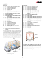
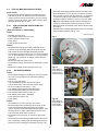
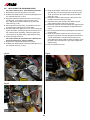
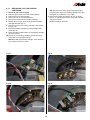
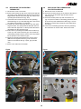
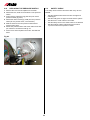
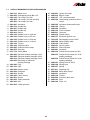
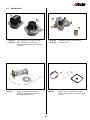
GB
Service Manual
Compact 3000
92x 93x 94x
Foreword
This service handbook is intended to assist with servicing and fault-finding in caravans and motor caravans
equipped with the Alde Compact 3000 92x-94x. The handbook may also be of assistance in ordering spare parts.
It also provides general information on how Alde central heating systems are designed, and how they operate.
When servicing components designed for LPG and 230 volts, national safety regulations must be adhered to.
After the boiler has been serviced, the service record must always be completed.
Alde International Systems AB
Service department
NB! We reserve the right to make changes after this handbook has been printed.
CONTENTS
Page Chap
3 1:0
4 1:1
5 2:0
5 2:1
6 3:0
6 3:1
7 3:2
7 3:2:1
7 3:2:2
8 3:2:3
8 3:3
9 3:4
9 3:5
9 3:6
9 3:7
9 3:8
10 4:0
10 4:1
10 4:2
Page Chap
11 4:3
11 4:4
11 4:5
12 4:6
13 4:7:1
14 4:7:2
15 4:8
15 4:9
16 4:10
16 5:0
17 6:0
18 6:1
19 6:2
19 6:3
20 6:4
21 6:5
21 6:6
22 7:0
23 7:1
24 8:0
25 9:0
26 9:0
About the Alde central heating system
Care of the heating system
About the Compact 3000
Technical data
Fault-finding
The electrical heating cartridge does not
work
The LPG boiler do not start
The LPG boiler shuts down on start-up
No ignition spark
Ignition spark is generated but the boiler
does not start
The LPG boiler starts but goes out after
approx. 10 seconds
The LPG boiler starts and switches off at
short intervals
Noisy fan
Noisy burner
Unstable or violent ignition
Other technical information
Replacing components
Replacing the printed circuit board
Replacing fan
Replacing a burner (new model)
Replacing the spark electrode
Replacing the flame sensor
Replacing the solenoid valve
Replacing a 1 kW heating cartridge
Replacing a 2 kW heating cartridge
Replacing the operating thermostat
Replacing the overheating protection
device
Replacing the pressure switch
Safety check
Wiring diagram with control panel 3000 266
Wiring diagram with control panel 3000 380
Wiring diagram for 3000 465
Wiring diagram for 3000 465 (with auxiliay
functions)
Wiring diagram for 3000 565 (with auxiliay
functions)
Circuit diagram 12 V and 230 V~
Flow chart 230 V~
Exploded diagram
Article numbers for exploded diagram
Faultfinding Compact 3000
Spare parts
Spare parts
1:0 ABOUT THE ALDE CENTRAL HEATING
SYSTEM
The central heating system uses two or three heat sources
– an LPG boiler and a 230 volt electrical heating cartridge,
as well as an externally-fitted heat exchanger for motor
caravans. The LPG boiler/heating cartridge heats up a
liquid mixture consisting of water (60%) and glycol (40%).
With the aid of a 12-volt circulation pump, which is located
in an expansion vessel, the warm glycol/water mixture is
circulated round the system through pipes and radiators.
Roof vent
Window
Air intake
Flue
Radiator
The radiators, which are fitted along the outer walls, heat
up the air, which rises and warms the walls and furniture.
As the warm air rises, it forms an air-barrier which keeps
the cold away from the windows.
The temperature inside the caravan is controlled by a 12
volt thermostat on the control panel.
Radiator
LPG boiler
Compact 3000
Heat exchanger 2968
1:1 Maintaining the heating system
Adding liquid:
Check the heating system’s fluid level regularly in the
expansion vessel. The level should be approximately 10
mm above the ”min” mark when the system is cold. The
heating system should be filled with a mixture of water
and glycol. For preference, use high quality pre-mixed
glycol (with inhibitor) intended for use in aluminium heating
systems. If using concentrated glycol, the mixture should
consist of 60% water and 40% glycol. If the heating system
will be exposed to temperatures below –25°C, the glycol
content must be increased, but not to more than 50%.
Any vessels used in handling the liquid must be spotlessly
clean, and the pipes in the heating system must be free of
contamination. This will prevent the growth of bacteria in
the system. The glycol mixture should be changed every
second year, since its ability to protect against corrosion,
for example, will deteriorate.
The glycol content should be checked before topping up
with new liquid. This will ensure that the concentration of
glycol in the mixture is not too high.
If the fluid level in the expansion tank falls for reasons other
than evaporation, check all joints, drain cocks and bleeder
screws to ensure that they are not leaking. If the glycolwater mixture leaks out, rinse with water and wipe up.
Never allow the heating system to stand empty of glycol
fluid.
Ensure that the vehicle is standing level, and check that
the bleeder screws and drain cocks are closed. Release
the plastic nut on the circulation pump, located on the
expansion vessel, and lift out the pump. Pour the glycol
mixture slowly into the expansion vessel, using a watering
can. When the system is being filled, air-pockets may form,
depending on how the pipe-system has been installed.
A good indication that there is air in the system is when
the heat only travels a few metres along the pipe from
the boiler, despite the fact that the circulation pump is
operating.
To make refilling and bleeding easier, we recommend using
the Alde filling pump which quickly both fills and bleeds the
system automatically.
Bleeding a caravan heating system (manually):
The LPG boiler must be switched on and the circulation
pump switched off. Start by opening the bleeder screws
(please refer to the vehicle instruction book for their
location). Leave them open until liquid escapes through the
spout at the air screw. Switch on the circulation pump and
let it run for a while. Check whether the pipes and radiators
all around the caravan are warm.
If air still remains in the system, try the following:
The LPG must be switched on and the circulation pump
switched off. Lower the front of the caravan as far as
possible using the jockey wheel. Leave it in this position for
several minutes, to allow any air to rise to the highest point
in the system. Open the bleeder screw at the highest point
and keep it open until all the air has escaped. Raise the
front of the caravan as high as possible using the jockey
wheel, and repeat the process. Return the caravan to a
horizontal position and start the circulation pump. Check
that the heat is circulating all around the caravan.
When bleeding a bogey wagon or a motor caravan, it is
easier to park on a steep slope, or raise the vehicle using a
jack.
Filling pump
Art no. 1900 811
2:0 ABOUT THE Compact 3000
How the boiler works.
The set-up of the boiler
When the room thermostat calls for heat, i.e. the
temperature in the vehicle is lower than the set room
temperature, the circulation pump starts. The liquid in
the heating system then starts circulating, and cold liquid
enters the boiler. The boiler’s operating thermostat senses
that the temperature of the liquid is too low. A signal
is sent to switch on the fan. When the pressure in the
pressure switch is sufficiently high, a signal is sent to the
electronics box to generate an ignition spark and to open
the solenoid valves to allow gas to enter the system. Once
the temperature in the vehicle has reached the temperature
set on the room thermostat, the circulation pump stops. The
operating thermostat senses that the liquid has reached the
right temperature and the boiler is switched off. When the
temperature of the liquid has fallen a few degrees again,
the boiler restarts. This ensures that there is always hot
liquid available when the room thermostat calls for heat,
and that the fresh water in the boiler is always warm.
An electrical heater works in the same way, but the signal
from the thermostat is sent to the relays which start the
electrical cartridges.
The boiler consists of three eccentrically-fitted pipes. The
innermost pipe is a heat exchanger made from extruded
aluminium. This is surrounded by a water jacket containing
a 40% glycol mixture which is the fluid for the heating
system. The fresh-water heater is located outside the water
jacket. The two outer pipes, as well as their ends and
connections, are made from stainless steel.
The heat exchanger is divided into two semi-circular parts
by a u-shaped baffle plate. The burner is located in the
upper semi-circle, the combustion chamber. The baffle
plate leads the flue gases back into the lower part of the
section, which constitutes the convection part.
The burner unit is fitted on the end of the heat exchanger.
It consists of a combustion fan, burner, solenoid valve with
built-in relief valve and intake/exhaust connections. The
exhaust gases escape through the inner tube, and fresh air
enters through the outer tube. The exhaust fumes exit the
vehicle via a hose and flue fitted either to the roof or to the
wall. Fresh air enters via the same flue (balanced draft).
2 or 3 electrical heating cartridges are fitted to the upper
part of the water jacket.
The output of the cartridges
Electronics
is either 2x1 kW or 3x1 kW
Thermostat
box
(alt. 2+1 kW), depending
on boiler model.
Overheating
Water jacket,
glycol mixture
Hot water jacket,
fresh water
protection
Electrical heating
cartridges
Pressure switch
Fan
Burner
Solenoid
valve
2:1 TECHNICAL DATA
Liquid volume / Pressure
Liquid volume, glycol mix:
Liquid volume, fresh water:
Max pressure, heating system:
Max pressure, fresh water:
Measurements:
Height Width Depth
Boiler size:
300 mm 345 mm 490 mm
Rec. Min. install. dimensions.310 mm 400 mm 550 mm
Weight:
6,5 kg
Gas:
Gastryck: I3+ 28-30/37 mbar, I3B/P 30 mbar, I3B/P 50 mbar
Output, Propane: 5,2 kW
Output, Butane: 6,0 kW
Consumption, Propane: 380 g/h
Consumption, Butane: 430 g/h
4,1 liter
8,4 liter
0,5 bar
3,0 bar
230 V ~
Output electrical cartridge (2 kW): 1050+1050 W
Output electrical cartridge (3 kW): 1050+1050+1050 W
12 V DC
Current consumption:
Fuse:
1 amp (max) incl. circ. pump
2 amp
BE AWARE OF THE RISKS OF 230 V DURING ALL SERVICE WORK
3:0 FAULTFINDING
Fig 1.
3:1 THE ELECTRICAL HEATING CARTRIDGE
DOES NOT WORK
Cause:
- Check that the changeover switches on the control panel
are in the correct positions (see operating instruction for
boiler).
- The 12 V fuse has blown.
- No or low voltage to the boiler. (< 12 V).
- 230 volt not connected.
- The overheating protection device has been triggered.
- The thermostat is broken/damaged
- Damaged printed circuit board.
- Damaged electrical heating cartridge.
- Faulty wiring or wire connections.
B
C
A
Fig 2.
Action:
During faultfinding, the hot water switch must be in the
ON position and the power plug switched to 2 or 3 kW
on the control panel.
- Check that the 12 V fuse (see fig. 1 A) is intact.
- Measure the input voltage. It must be no lower than
10.8 V.
- Check that the 230-volt cable is connected and that the
vehicle is connected to a 230-volt outlet.
- Check that the overheating protection device has not
tripped. If necessary, reset by first unscrewing the black
protective cap, then pressing down the reset button (see
fig. 1 B). When the overheating protection device has
been reset, there must be a 12-volt input on one flat-pin
terminal and 12-volt output on the other (see fig. 2 A),
otherwise it is defective and must be replaced.
N.B! If the overheating protection device has tripped
it cannot be reset until the boiler has cooled 10-20°C.
Before the boiler is restarted, check that it has been bled
thoroughly.
- Check that the operating thermostat is turned to the
maximum clockwise position (see fig. 1 C).
- Check that there is voltage (12 V) on flat-pin terminal
12 (grey cable, low temperature) and terminal 22 (blue
cable, high temperature), see fig. 2. If there is no voltage
on terminals 12 and 22, but there is voltage on terminal
11 (red cable), the operating thermostat must be replaced.
- Check that there is voltage on pos. 9 on the P1 printed
circuit board (see fig. 3). If not, the printed circuit board
must be replaced.
- Check that there is voltage on pos. 12 and 15 on the P1
printed circuit board (see fig. 3). If not, there is a fault in
the wiring or on the control panel.
- Check the resistance of the electrical heating cartridge
(approx. 50 ohm for 1 kW, and 25 ohm for 2 kW) and the
insulation to earth (> 1 Mohm). In the event of a fault,
replace the cartridge.
- Check that the wiring connections are intact and correctly
fitted.
- If none of the above measures solves the problem,
replace the printed circuit board. The fault will lie in the
control relays for 12/230 volts.
A
Grey 12
Blue 22
Red
Red 11
Fig 3.
9
12
15
3:2 THE LPG BOILER DOES NOT START
When the overheating protection device has been reset,
there should be a 12-volt input on one flat-pin connector,
and a 12-volt output on the other (see fig. 2 A), otherwise
it is defective and must be replaced. The overheating
protection is broken if there is 12 volt on only one cable.
NB! If the overheating protection device has tripped, it
cannot be reset until the boiler has cooled by 10-20°C.
Before the boiler is restarted, check that it has been bled
thoroughly.
- Check that the operating thermostat is turned to the maximum clockwise position (see fig. 1 C).
Initial check:
- Disconnect the ignition cable from the electronics box
and start the boiler. The electronics box should make a
clicking sound for about 10 seconds. If you can hear the
clicking, continue to section ”3:2:3 Ignition spark is generated but the boiler fails to start”.
3:2:1 THE LPG BOILER SHUTS DOWN ON
START-UP
”Red LED comes on immediately”
Cause:
continue page. 8
- Resetting time too short.
- The pressure switch does not cut out.
- Fault in electronic ignition unit.
- Faulty wiring.
- Faulty printed circuit board.
Fig 4.
Action:
- Reset the electronic ignition unit by switching off the
boiler on the control panel (the red LED goes out) and
wait at least 30 seconds before attempting a restart.
- Check that the pressure switch cuts out. There should be
12 V on the white cable, connection no.1 on the pressure
switch (fig. 4 A). If there is no voltage, replace the pressure switch.
- Replace the electronic ignition unit
- Check that the wiring connections are intact and correctly
fitted.
- Replace the printed circuit board with a new one.
B
A
Fig 5:1.
Hose fitting on
press-cast burner
housing (shiny,
smooth surface)
3:2:2 NO IGNITION SPARK
Cause:
- Check that the changeover switches on the control panel
are in the correct positions (see the boiler operating
instructions.
- The 12 V fuse has blown.
- The overheating protection device has tripped.
- The red LED on the control panel is lit (shut-down)..
- No or low voltage on the boiler (< 12 V).
- The operating thermostat is broken/damaged.
- The pressure generated by the fan is too low.
- The pressure switch does not come on.
- The printed circuit board is damaged.
- Faulty electronic ignition unit.
- Faulty wiring.
Fig 5:2.
Hose fitting on
sand-cast burner
housing (dull,
rough surface)
Action:
- Check that the 12 V fuse (see fig. 1A) is intact.
- Reset the electronics by switching off the boiler on the
control panel (the red LED light goes out) and wait
approx. 20-30 seconds before attempting to restart. If the
red LED comes on again, please refer to section ”3:2:1
The LPG boiler shuts down on start-up”.
- Check the incoming voltage, is must be no lower than
10.8 V.
- Check that the overheating protection device has not tripped. If necessary, reset by first unscrewing the black protective cap, then pressing the reset button (see fig. 1 B).
- Remove the nozzle and blow the nozzle and gas pipe
clean.
- Check the wiring contact points again.
- Check that the exhaust cowl and the intake/exhaust
hoses are free from objects that may obstruct the air
supply.
- Check that there is voltage (12 V) on flat-pin terminal
12 (grey cable, low temperature) and terminal 22 (blue
cable, high temperature) see fig. 2. If there is no voltage
on terminals 12 and 22, but there is voltage on terminal
11 (red cable), the operating thermostat must be replaced.
- Check that the hoses (fig. 5:1 or 5:2) between the fan
housing and pressure switch are intact and correctly
fitted.
- Check that the voltage to the fan is at least 9 volts +/-0.2
and that no abnormal noise can be heard. At 9 volts, the
current consumption shall be approx. 0,4-0,6 A. In the
event of a fault, change the fan.
- Check that the pressure switch is making a clicking noise
2-5 seconds after the fan has started, or check that there
is voltage on the flat-pin terminal of the blue cable, connection no. 2 (see fig. 4 B).
- If the fan does not start, check that there is 12V in both
the red and white cables. If there is 12V only in the red
cable, the pressure switch should be replaced.
- Check that the wiring connections are intact and are correctly fitted.
- Replace the electronic ignition unit. If this has no effect,
replace the printed circuit board.
Spark
electrode
Flame
sensor
2,5-3,5 mm
Fig 6.
3:2:3 IGNITION SPARK IS GENERATED BUT THE BOILER DOES NOT START
Cause:
Spark
electrode
- No or poor gas supply.
- No or faulty spark on the spark electrode.
- The solenoid valves do not open.
- Faulty soft start valve.
- Faulty electronic ignition unit.
- Nozzle blocked.
- Faulty wiring.
- Flue blocked.
Flame
sensor
Action:
- Check that the gas pressure to the boiler is correct (28-50
mbar).
- Check that the ignition cable is intact and that there are
no short-circuits along the cable
- Check when starting that voltage is being supplied to the
solenoid valves. If not, replace the electronic ignition unit
- Check that a clicking sound can be heard from the solenoid valves. Check the valves one at a time by removing
the flat-pin contacts. Replace if there is a fault.
- Remove the soft start valve (see the exploded diagram)
and attempt to restart. If the boiler now ignites, the soft
start valve must be changed. (NB! The boiler ignites a
little harder without the soft start valve).
- Remove the burner and check that the spark electrode is
intact and correctly fitted (see fig. 6). Replace if necessary.
3:3 THE LPG BOILER STARTS BUT GOES OUT AFTER APPROX. 10 SECONDS
(RED LED COMES ON)
Cause:
- The flame sensor cable is damaged.
- Faulty electronic ignition unit.
- Sensor damaged or incorrectly positioned.
Action:
- Check that the flame sensor cable is intact and correctly
connected.
- The only way to check whether the electronic ignition unit
is working is to change it and then check that the boiler is
operating properly.
- Remove the burner and check that the flame sensor is
intact and correctly fitted (see fig. 6). Replace the flame
sensor if necessary.
3:4 THE LPG BOILER STARTS AND SWITCHES OFF AT SHORT INTERVALS
Cause:
- Check that the flue is free from objects that may obstruct
the air circulation.
- Check that the gas pressure to the boiler is correct
(28-50 mbar).
- Where the ignition is unstable, remove the soft start valve
and test-start the boiler. The start should now be stable,
but with a more violent ignition than normal. Replace with
a new soft start valve or clean the old one and carry out
another test-start.
- Unscrew the nozzle and check that it is marked ”230”.
- Detach the ignition cable from the electronic ignition unit
and start the boiler. A clicking sound should be heard
from the electronic ignition unit, with a frequency of
at least 2 Hz at 12 volts (two clicks per second). If the
frequency is too low the ignition electronics must be
replaced.
- Check that the ignition cable is intact and that there are
no short-circuits along the cable.
- Remove the burner and check that the spark electrode
is correctly fitted (see fig. 6) and undamaged. Replace/
adjust if necessary.
- Using a leakage tester, for example, check that no gas
is passing through the boiler when it is switched off. If
a leak is discovered, check that all gas connections are
tight. If there is no noticeable external leakage, replace
the solenoid valve.
- Voltage to boiler too low (< 12 V).
- Poor contact point in the wiring (earth fault).
- Pressure switch damaged or incorrectly connected.
- Ignition unstable.
- Flue blocked.
Action:
- Measure incoming voltage. It must be no lower than
10.8 V.
- Check the wiring connections, particularly the earth connections.
- Check that both hoses between the pressure switch and
the fan housing are connected (see fig. 5).
- Replace the pressure switch.
- If the problem persists, please refer to ”Unstable or violent ignition”.
- Check that the exhaust cowl and the intake/exhaust
hoses are free from objects that may obstruct the air
supply.
3:5 Noisy fan
Cause:
- The fan motor is damaged (worn).
- Impeller out of balance.
- Impeller touches fan housing.
Action:
3:8 other technical information
- Remove the fan and check whether the impeller has
touched the fan housing (wear marks on the fan housing). If necessary adjust the fan housing axially.
- Replace the fan.
• The electronic ignition unit may emit a slight high frequency sound during operation.
• Boiler models 3000 92x and 3000 93x are intended only
for roof flues.
• Boiler model 3000 94x is intended only for wall flues.
• Boilers with manuf. no. 10921 and higher have circuit
board rev C, which means that the fan does not start if
the pressure switch is ”on”, and there is a new voltage
stabilisation which handles lower voltages (10 V).
• Boilers with manuf. no. 7536 and lower may have a fault
in the fan that causes a whistling sound.
• If there is a resonant noise on boiler model 3000 94x,
insulate the exhaust hose with insulation hose art. no.
1900 233.
• If the fuse (F2) has blown, the boiler should not be repaired but should be replaced with a new boiler.
• Insulate the outer pin on the solenoid valve so that it
cannot come into contact with the end plate. If this should
happen, the electronics box short-circuits and must be
replaced.
• In order to simplify operation and maintenance, fitting
automatic air bleeders on the installation can be
recommended.
3:6noisy burner
Cause:
- Whistling sound from the burner on 92x-93x. Change to
burner 3000 516.
3:7 UNSTABLE OR VIOLENT IGNITION
Cause:
- The exhaust/intake hoses are too short.
- The exhaust/intake hoses are damaged or loose.
- The exhaust cowl is blocked.
- Incorrect gas pressure.
- Blocked or faulty soft start valve.
- Faulty nozzle.
- Low spark frequency.
- The pressure switch does not shut off or has stuck.
- The solenoid valves are leaky.
Action:
- Check that the intake/exhaust hoses are at least 2 metres
long and that they are undamaged and correctly fitted at
the boiler and flue (if a wall flue is fitted, 0.7-1.5 m).
4:0 replacing components
Always switch off 12 V DC and 230 V ~ power supply and turn the main gas cock to "off" position before starting
any servicing. The seals (marked in red) must NOT be broken unless special permission has been obtained from
Alde.
4:1Replacing the printed circuit
4:2 replacing fan
board
1. Remove the cover and the service panel from the boiler.
1. Remove the cover and service panel on the boiler.
2. Detach the blue (N) (fig. 7 A) and brown (R) (fig. 7 B)
cables at the cable ports on the printed circuit board,
and remove the blue (N) (fig. 7 C), brown (R) (fig. 7 D)
and red (R) (fig. 7 G) cables from the electrical heating
cartridge.
3. Detach the white 15-point connection block (fig. 7 E)
from the printed circuit board.
4. Remove the screw behind the connection block (fig 7H).
5. Remove the printed circuit board by pressing together
the hooks on the 5 plastic spacers (fig. 7 F), and pulling
out the circuit board.
6. Push the new board firmly into the spacers and connect
the cables as shown in fig. 7.
7. Refit the service door and cover and test-run the
electrical heating cartridge.
2. Disconnect the positive (red, fig. 8 A) and negative
(black, fig. 8 B) cables on the fan motor.
3. Unscrew the plastic housing from the motor, 2 screws
(fig. 8 C).
(NB! On boilers with wall flues (94x) item 3 shall be
ignored.)
4. Unscrew the 4 plate screws (fig. 9 C) securing the fan to
the fan housing.
5. Tilting the fan towards the boiler body, lift it upwards out
of the fan housing (see fig. 10).
6. Fit the new fan by following these instructions in reverse.
NB! Take care not to damage the impeller when fitting
the fan.
7. Fit the service panel and lid and test-run the boiler.
(NB! In a small number of boilers, the gas pipe is fitted
in such a way that the fan cannot be extracted without
first removing the gas pipe. Do not forget to check that
the seal is tight).
Fig 7.
Fig 9.
C
G
A
D
F
E
F
C
B
F
C
H
Fig 8.
Fig 10.
B
A
C
10
4:3
replacing the burner
NB! Items 9-12 shall be ignored on boilers with manufacturing no 3000 9xx B and on boilers where burner
3000 516 is installed.
9. Adjust the pressure switch screw 1/2 turn clockwise
10.Remove the as in item 4.2 and the under the inlet plate
under impeller by removing the two screws.
11.Install the new inlet plate, and then put back the old one,
two screws.
12.Remount the fan in reverse order.
NB! Take care that the impeller does not get damaged
during fitting. Check that the fan does not make an
unpleasant noise.
13.With the boiler operating, check the system and connections for any leaks using a leak detector spray. Once
this is done, fit the end plate and cover.
Applies to boiler models 3000 927 and later. If the
burner is replaced, burner 3000 516 should be installed.
1. Remove the cover and end plate from the boiler.
2. Detach the spark electrode and sensor cables from the
electronic ignition unit.
3. Using two spanners, unscrew the nut on the gas pipe
(fig. 11 A) between the burner and the solenoid valve
(fig. 11 B).
4. Remove the end plate with burner by slackening the
screws (fig. 11 C) on the burner housing.
5. Pull the end plate with burner straight out of the burner
housing (fig. 12).
6. Fit the new burner (insert it straight in) and secure it via
the end plate in the burner housing (fig. 11 C).
7. Secure the gas pipe to the solenoid valve (fig. 11 B) and
to the burner (fig. 11 A). Remember to check that the
cones are correctly fitted to the pipes. Using two spanners, tighten the nuts on the gas pipe to 7-9 Nm (fig 11).
8. Fit the ignition spark and flame sensor cables to the
electronic ignition unit.
4:4REPLACING THE SPARK ELECTRODE
When replacing the spark electrode, also replace the
flame sensor.
1. Detach the burner as per instructions in 4:3.
2. Remove the nut (fig. 13 A) and pull the spark electrode
(fig. 16 B) straight backwards.
3. Fit the new spark electrode and secure it. Check that the
distance between the tip of the spark electrode and the
mesh cover of the burner is 2.5-3.5 mm, and that the
spark electrode is correctly positioned (see fig. 6).
4. Fit the burner in accordance with instructions and teststart the boiler.
Fig 11.
4:5Replacing the flame sensor
When replacing the flame sensor, also replace the
spark electrode.
B
A
1. Detach the burner in accordance with 4:3.
2. Remove the nut (fig. 13 C) and pull the flame sensor
(fig. 13 D) straight backwards.
3. Fit the new flame sensor, ensuring that the tip of the
flame sensor is positioned above the burner in accordance with fig. 6. Secure the flame sensor.
4. Fit the burner in accordance with instructions and teststart the boiler.
C
Fig 12.
Fig 13.
A
B
C
D
11
4:6 replacing the solenoid valve
3. Using two spanners, slacken the nuts on the incoming
gas pipe (fig. 15 A) and the gas pipe to the burner (fig.
15 B), and remove the rubber cap from the soft start
valve (fig. 14 D).
4. Detach the pressure switch hoses to and remove the
insulation next to the burner housing.
5. Unscrew the two plate screws which fasten the gas
valve angle bracket to the burner housing.
6. Extract the solenoid valve and transfer the angle bracket
to the new solenoid valve (attached underneath with a
screw).
7. Fit the new solenoid valve by following the instructions in
reverse order.
8. Using two spanners, tighten the nut on the incoming
gas pipe to 25-30 Nm, and the gas pipe to the burner to
7-9 Nm. Remember to check that the bevels are correctly fitted to the pipes. With the boiler operating, check
the system and connections for any leaks using a leak
detector spray.
9. Fit the end plate and cover.
For boilers with serial no. from 04445 and upwards.
1. Remove the cover and end plate on the boiler.
2. Unfasten the cables (black, brown and yellow/green) on
the solenoid valve (fig. 14 A-C).
3. Using two spanners, slacken the nuts on the incoming
gas pipe (fig. 15 A) and the gas pipe to the burner
(fig. 15 B), and remove the rubber cap from the soft
start valve (fig. 14 D).
4. Extract the solenoid valve (fig. 16) and fit the new one
by following the instructions in reverse order.
5. Using two spanners, tighten the nut on the incoming gas
pipe to 25-30 Nm, and the gas pipe to the burner to 7-9
Nm. With the boiler operating, check the system and
connections for any leaks using a leak detector spray.
6. Fit the end plate and cover.
For boilers where the solenoid valve is fitted to the
burner housing (up to serial no. 04444).
1. Remove the cover and end-plate on the boiler.
2. Unfasten the cables (black, brown and yellow/green) on
the solenoid valve (fig. 14 A-C).
Fig 16.
Fig 14.
D
A
B
B
C
A
Fig 15.
A
B
12
4:7:1 Replacing the 1 kW heating
cartridge
1.
2.
3.
4.
5.
6.
NB! Check that the rubber plug is fully inserted and
push the lower edge of the heating cartridge while tightening the nut. Tighten the nut to 4 Nm.
11. Connect the cables according to fig. 20, (A=brown,
B=blue, C=yellow/green). Fit the cover and end plate.
Add glycol mixture.
Bleed and test-run the boiler.
Fig 17.
Fig 19.
Fig 18.
Fig 20.
Switch off 230 V power supply
Drain the glycol mixture from the heating system.
Remove the cover and end plate.
Remove the fan in accordance with 4.2
Remove the cables from the heating cartridge.
Slacken the nut in the centre of the electrical heating
cartridge electrode (fig. 17).
7. Give the t-screw on the heating cartridge a one-quarter
turn (fig. 18).
8. Extract the heating cartridge by pulling straight backwards (fig. 19).
9. Clean around the edges where the old heating cartridge
has been located.
10.Then fit the new heating cartridge, give the t-screw a
one-quarter turn and tighten the nut.
NB! Before fitting the heating cartridge, check the direction in which to turn the t-screw.
B
C
A
13
4:7:2 Replacing the 2 kW heating
cartridge
1.
2.
3.
4.
Switch off 230 V power supply
Drain the glycol mixture from the heating system.
Remove the cover and end plate.
Remove the burner together with the solenoid valve (fig.
21). Do not slacken the gas pipe, this is in order to avoid
having to check sealing.
5. Remove the cables from the heating cartridge.
6. Slacken the two plate screws and remove the supporting angle bracket from the heating cartridge (does
not apply to boilers with serial numbers of 4445 or
higher).
7. Slacken the nut in the centre of the electrical heating
cartridge electrode and unscrew it approximately 10 mm
(fig. 22)
8. Tap the nut lightly to release the rubber plug and extract
the heating cartridge by pulling straight backward. If
there is a T screw on the heating cartridge (the screw
has a groove), the nut must be unscrewed sufficiently
for the T screw to be turned a quarter turn before the
heating cartridge can be pulled out.
NB! Leave the nut on the screw, with several turns
of thread in it.
9. Clean round the edges where the old heating cartridge
was. Then fit the new heating cartridge. Before fitting
it, check the direction of the T screw, push the heating
cartridge in and turn the T screw a quarter turn. Then
pull the nut so that the T screw comes into the correct
position (the screw should be at the same height as the
cable connections). Tighten to 4 Nm. Check that the T
screw projects 15-18 mm from the nut (otherwise there
is a risk that the T screw is not in the right position).
10.Any angle bracket should not be fitted. Fit the solenoid
valve in accordance with the instructions. Connect the
cables as shown in fig. 23 (A=brown, B=blue, C=yellow/
green, D=red). Fit the cover and end plate. Add glycol
mixture. Bleed and test-run the boiler.
Fig 21.
Fig 23.
Fig 22.
A
B
C
14
B
D
4:8Replacing the operating
thermostat
4:9 Replacing the overheating
protection device
1. Remove the cover on the boiler.
2. Remove the locking clip (fig. 24 A). Remove the split pin
(fig. 24 B) on the immersion pipe. Remove the overheating protection device sensor first (fig. 25), and then the
operating thermostat sensor (fig. 26 A).
3. Unscrew the two screws which secure the operating
thermostat (fig. 27 A) to the fastening plate, and remove
the cables from the flat-pin connections.
4. Transfer the contact spring (fig. 26 B) to the new operating thermostat. The spring must be fitted with the rear
end of the bulb uppermost, so that it pushes the sensor
downwards into the immersion pipe.
5. First insert the operating thermostat sensor all the way
to the very end of the immersion pipe. Then insert the
overheating protection device sensor as far as possible.
Fit the split pin on the immersion pipe.
6. Attach the operating thermostat to the service panel
(NB! Use the original screws only) and connect the
cables in accordance with fig. 2 (blue, grey and two
red).
7. Fit the cover and test-run the boiler.
1. Remove the cover on the boiler.
2. Remove the locking clip (fig. 24 A). Remove the split pin
(fig. 24 B) on the immersion pipe and take out the
sensor (fig. 25).
3. Remove the black plastic cap and unscrew the nut
(fig. 27 B) which holds the overheating protection device
to the service panel. Release the cables (fig. 2 A) from
the flat-pin contacts and change the overheating prote
tion device.
4. Fit the new overheating protection device by following
the instructions in reverse order. Test-run the boiler.
Fig 24.
Fig 26.
A
B
A
B
Fig 25.
Fig 27.
A
B
15
4:10Replacing the pressure switch
5:0
1. Remove the cover and end-plate from the boiler.
2. Detach the blue, white and red cables on the pressure
switch.
3. Push back the metal securing plate and pull out the
pressure switch (fig. 28 A).
4. Detach the rubber hoses (fig. 28 B) from the pressure
switch (do not pull the hoses, unscrew them).
5. Refit the hoses to the new pressure switch before
pushing it into place.
6. Fasten the pressure switch and fit the cables to the flatpin contacts in accordance with fig. 28.
7. Fit the cover and end plate to the boiler. Test-start the
boiler.
The safety check must be carried out after every service.
Safety check
Check:
• That the intake/exhaust hoses and flue are tight and
undamaged.
• That the LPG pipes are tight. Pressure test the system.
• That the 230 V~ earth cable is connected.
• That the safety valve on the water heater is not blocked.
• That the heating system is filled with glycol mixture
up to the mark on the expansion vessel.
Fig 28.
A
Blue
Red
White
B
16
6:0 wiring diagram with control panel 3000 266
17
6:1 wiring diagram with control panel 3000 380
18
6:2 wiring diagram with control panel 3000 465
6:3 wiring diagram with control panel 3000 465 (with auxiliary functions)
19
6:4 wiring diagram with control panel 3000 565 (with auxiliary functions)
20
6:5circuit diagram 12V and 230 V ~
6:6 Flow chart 230 V ~
21
7:0 exploded diagram
1
2
47
6
54
53
2
52
7
4
7
6
5
51
3
8
9
10
13
11
8
12
55
50
19
18
16
17
25
23
22
24
43
29
30
31
56
42
41
21
28
49
47
46
2
33
40
39
38
32
37
34
35
36
2
22
20
27
48
45
44
14
2
26
47
15
7:1 Article numbers for exloded diagram
1. 3000 133
2. 2900 258
3. 3000 195
3000 452
3000 409
4. 3000 247
5. 3000 372
6. 3000 297
7. 3000 324
8. 2930 414
9. 3000 196
10. 3000 196
11. 3000 196
12. 3000 196
13. 3000 138
14. 3000 168
15. 3000 289
16. 3000 278
17. 2737 174
18. 3000 256
3000 250
3000 315
3000 255
19. 3000 240
20. 3000 159
21. 3000 528
22. 3000 204
23. 3000 213
24. 3000 206
25. 3000 501
26. 3000 205
27. 3000 383
28. 2930 235
29. 3000 407
30. 3000 516
31. 3000 127
32. 3000 362
33. 3000 365
34. 3000 185
35. 3000 246
36. 3000 132
37. 3000 231
38. 3000 232
39. 3000 157
40. 7410 325
41. 3000 286
42. 2762 125
43. 3000 351
44. 3000 131
45. 3000 261
46. 3000 330
3000 333
3000 334
47. 3000 367
48. 3000 184
49. 3000 327
50. 4071 011
51. 3000 460
52. 3000 251
53. 2959 120
54. 3000 290
55. 3000 143
56. 3000 166
Metal cover
Self-tapping screw B6 x 9.5
Fan compl. (for 921)
Fan compl. (for 92x and 93x)
Fan compl. (for 94x)
Insulation
Double clip
Rubber cap
Double clip
Sleeve
Rubber hose, L=190 mm
Rubber hose, L=55 mm
Rubber hose, L=330 mm
Rubber hose, L=110 mm
T-piece
Soft start valve
Solenoid valve compl.
Gas pipe
Screw M4x8
Electrical heating cartridge 1 kW
Electrical heating cartridge 2 kW
Electrical heating cartridge 3 kW
Blind plug for electrical
heating cartridge
Plug
Pipe
Nozzle compl.
End plate
Gasket
Flame sensor
Burner
Spark electrode
Nut
Cable grommet
23
Ignition kit compl.
Burner compl.
”SIT” pressure switch
Overheating protection device
compl.
Operating thermostat compl.
Casing
Insulation
Front end plate
Grommet
Plastic spacer
Electronic ignition unit
Self-tapping screw 2.9x25
Mains supply cable
Cable clamp
Service panel
Rear end plate
Insulation
Printed circuit board (for 921)
Printed circuit board (for 3 kW
heating cartridge)
Printed circuit board (for 2 kW
heating cartridge)
Wiring loom for 230 V
Wiring loom
Spring
Retaining clip
Boiler body compl.
Insulation
T-piece
Pressure relief valve
Pipe
Fuse 2 A
8:0guide for fault finding on Compact 3000
Guide for faultfinding on Compact 3000
Neither electricity
nor gas working
Yes
No
Only gas not
working
Yes
No
Is the pump
working
Only electricity
not working
Red lightemitting diode lit
Is the fan
working
No
Yes
Yes
Is the fan
working
Voltage 8.8-9.2 V
Current 0.4-0.6 A
Yes
No
Voltage
(230 V)
No
Yes
Hoses
Overheating
protection
Fuse
(2A)
Circuit card
(Re 2, 3, 4)
Pressure switch
does not return
Ignition electronics
(click in gas valve)
(ignition spark)
Pressure switch
(blue cable)
Thermostat
Circuit card
(Re 7)
Circuit card
(Thermal fuse 88º C)
Panel
Sparking plug
Panel
Sensor pin
Gas supply
Panel
24
No
Voltage
fan
8,8-9,2 V
Yes
No
Fan Pressure switch
(white cable)
Circuit card
(Re 5)
Panel
9:0spare parts
1
1
2
2
1. 3000 452
2. 3000 409
Fan complete (9 V for 3000 92x-93x)
Fan complete (9 V for 3000 94x)
Packed in cardboard box with Allen key
for impeller
1. 3000 289 Solenoid compl. inc. soft start valve
2. 3000 168
Soft start valve.
3000 516
Burner set including throttle plate
(Replaces earlier models 3000 385,
3000 408 and 3000 444).
3000 407 25
Ignition kit incl. spark electrode, flame
sensor, cable grommet and gasket (for all
models)
9:0spare parts
1
1
2
2
1. 3000 333
2. 3000 334
1
Printed circuit board (92x-94x with 3 kW heating cartridge
Printed circuit board (92x-94x with 2 kW heating cartridge
1. 3000 365
2. 3000 362
Operating thermostat ”lmit” including
retaining clip
Overheating protection device ”lmit”
compl.
2
1
2
3
4
3
1.
2.
3.
4.
3000 127 3000 157
3000 471
3000 290
SIT” pressure switch
Electronic ignition unit
Hose nipple with in-built non return valve
Pressure release valve
1. 3000 256
2. 3000 250
3. 3000 315
26
Electrical heating cartridge 1 kW
Electrical heating cartridge 2 kW
Electrical heating cartridge 3 kW
27
Wrangels allé 90 • Box 11066 • S-291 11 Färlöv • Sweden
Tel +46 (0)44 712 70 • Fax +46 (0)44 718 48 • www.alde.se • [email protected]
Service 3000 Rev 921 GB
Alde International Systems AB