1
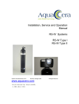
2S and 3S Under-Counter UltraFiltration Drinking Water System Installation and Service Manual Table of Contents Section I. Introduction Section II. Specifications Section III. Preparation Section IV. Installation Steps Section V. Operation and Maintenance Section VI. Trouble Shooting Exploded View and Parts List Caution: The Centers for Disease Control and Prevention (CDC) and the Environmental Protection Agency (EPA) have issued guidance to people with severely weakened immune systems who may want to take extra precautions to reduce the risk of infection with Cryptosporidium from drinking water. This guidance pertains to people with HIV/AIDS, patients receiving treatment for cancer, recipients of organ or bone marrow transplants, transplant patients taking immunosuppressive drugs, and persons who have congenital immunodeficiencies. The EPA has stated that they do not know the importance of drinking water compared to other possible sources of Cryptosporidium to determine how most people become infected. The CDC-EPA guidance suggest that immunosuppressed individuals discuss their risks with their health care provider. All individuals should take adequate precaution when changing the filter cartridges, including wearing protective gloves, to avoid direct contact with the exhausted cartridges. Section I. Introduction Your new Teros™ Drinking Water System uses a combination of innovative filtration technologies to reduce unwanted contaminants in your water supply. The following steps combine to give you the best in clear, sparkling pure drinking water. Your system will include 2 or 3 filters depending on the model you chose. This manual will cover both systems. Teros™ 2S Teros™ 3S Water Inlet Water Inlet Water Outlet Water Outlet Section II. Specifications System Ratings and Operating Parameters System Rating U.S. Production 0.5 G.P.M.— 0.75 G.P.M. Capacity 1100 Gallons AMB-9S 1000 Gallons FD-MultiMedia 2000 Gallons Teros-UF Membrane Recommended Operating Limits for Feed Water Water Pressure 20—125 psi Total Dissolved Solids Less than 500 ppm or 500 mg/l Temperature 35— 110 ° F 2— 43 ° C pH 6.5 to 8.5 recommended Iron Less than 0.5 ppm 0r 0.5 mg/l Manganese Less than 0.05 ppm Or 0.05 mg/l Hydrogen Sulfide Less than 0.3 ppm Or 0.3 mg/l Chlorine 0— 10 ppm Section III. Preparation 1. 3/8” variable speed drill 2. Extension work light 3. Safety glasses A. System Components 4. 7/16” carbide drill bit 5. 1/8” metal drill bit for pilot hole. The following components comprise the Teros Systems. 6. Center punch and hammer 7. Phillips head and flat blade screwdrivers Housing Top Assembly 8. Tubing cutter 2 Housing sumps with O-rings 9. Paper towels, broom and assorted clean up ma Lead-Free drinking water faucet terials EZ-Adapter valve Plastic tubing and connectors C. Site Selection AMB-9S AquaMetix block candle The Teros system was designed to fit under a sink, Teros UF Membrane however, because of space limitations or other reasons, *FD-MultiMedia— Only on 3S model. the system’s flexible design allows for other locations. B. Tools Recommended for Installation When determining the location remember that access to a cold water tap line and ease of filter replacement are The following tools will cover most of the installation important considerations. sites encountered. All components and tubing should be located in an area which is not exposed to freezing temperatures. If winter temperatures are sever, the area should be Above the minimum temperature listed in the table on page 4. Do not expose the unit or tubing to direct sunlight. 3. Attaching the faucet SEE Diagram below for visual. NOTE: faucet for illustration purposes only. 1. Faucet should be placed near the sink where drinking water is normally obtained. Convenience of use, and an open area beneath the faucet under the sink for attaching product and tubing are also considerations. 2. System can be installed on either the right or left side of the under-sink area or a cabinet. The right side is recommended because all the tubing will be to the back of the cabinet and out of the way. Installation in the basement is also an option, one location is near the laundry/utility sink where cold potable water is handy. The mounting location should allow adequate clearance and accessibility for filter changes. 3. Feed water connection — Use a potable COLD water supply only. Section IV. Installation Steps All plumbing should be done in accordance with state and local plumbing codes. A. Faucet Installation– the easiest installation is to use an existing spray attachment hole. If the spray faucet hole is not available, then the sink top must be drilled. Choose a convenient location as described in Section III. 1. mark the location of the center of the faucet base. 2a. Drilling a stainless steel sink: Center punch the hole to provide a starting point for the drill Drill a 7/16” hole Clean away any chips Debur any sharp edges 2b. Drilling a porcelain sink: It is best to use a special 7/16” diameter cutter designed for porcelain. A carbide tipped masonry bit is a second choice. Place a piece of tape over the area to be drilled to help prevent chipping. Drill a pilot hole for the porcelain cutter. When drilling the 7/16” hole, drill slowly and carefully; the porcelain chips easily After drilling, clean the area well. Iron filings, if left in place, can cause rust stains. 2c. Drilling a counter top: NOTE: treat ceramic tile as porcelain until the tile is penetrated, then use the carbide tipped metal cutter. Formica counter tops may be drilled with a good 7/16” wood bit, drilling a 3/32” pilot hole will help keep the bit going straight. Cold water line connection will be one of the following: Feed Water Saddle Valve OR EZ Adapter B. Feed Water Saddle Valve Installation Decide on location. Do NOT connect to a hot water feed line. 1. Shut off the water supply and drain the line 2. Copper tubing supply line: Turn the handle of the feed water saddle valve counter clockwise until the lance does not protrude from the gasket. It may have to be pushed in. Assemble the feed water saddle valve on the tubing. For 3/8” OD tubing use the back plate side with the small groove to prevent distortion of the tubing For larger tubing (up to 5/8” OD) use the large groove of the back plate. Assemble and tighten the brass screw. To pierce the tubing, turn the valve handle fully clockwise. A small amount of water may escape from the outlet until it is fully pierced. When you feel the valve handle firmly seated in the clockwise direction, the copper tube is pierced and the valve is closed. EZ Adapter Valve EZ Adapter Valve Installation Turn off the cold water supply valve under the sink. If there is no valve, turn off the water to your house at the main meter. 1. Open the cold water faucet to let off pressure. Make sure the valve is off and the faucet is not dripping. 2. Unscrew the nut that holds the cold water supply line into the pipe where you just turned the water off from. 3. Install the EZ adaptor on the exposed threads and tighten. 4. Reinstall the nut with the cold water supply line onto the top of the EZ adaptor fitting and tighten. NOTE: Do NOT turn the cold water line back on yet, the water will flow directly out of the EZ adaptor and flood your kitchen. C. Housing Assembly Installation Locate the site per section III. Various installation sites will require different types of mounting fasteners; be sure the fastener selected will provide a firm, solid mounting. A support panel may be necessary on thin cabinet walls or to span between wall studs on particleboard or drywall. Do not drill through exterior cabinet walls or leave sharp wood screw points exposed in readily accessible cabinet interiors. The close proximity of a dishwasher or a trash compactor may require special fabrication of a mounting plate. 1. The mounting bracket will accept either #10 or #12 mounting screws spaced on 6” centers. Allow at least 4” of clearance beneath the filter housings to accommodate filter changes. Mark the two locations (the bracket can be used as a template). Install the screws and tighten them until the heads are about 5/8” from the wall. 2. Locate the 1/4” red feed water tubing. Insert the tubing into the “Inlet” labeled push-fitting on the filter system. Reference the special supplement sheet in the carton for proper connection of all tubing. Run the tubing along its course to the feed water saddle valve or EZ adapter and trim to length. 3. Locate the blue section of tubing. Insert the tubing into the “Outlet” labeled push-fitting on the filter system. The fittings will grab the tubing and seal it in place. Make sure the tubing is pressed all the way in to create a pressure tight connection. Run the blue tubing along its course to the dispensing faucet. Trim to length. To the end of the 7/16” stud on the faucet screw on the white faucet quick connect fitting. Once snug by hand take a pair of pliers and tighten the fitting an additional half turn. DO NOT OVER-TIGHTEN. NOTE: if you want to pull the tubing out for some reason, push the ring around the tubing in and pull the tubing out. 4. Hang the Housing Assembly onto the mounting screws and tighten. DO NOT OVER-TIGHTEN. D. Start Up Final Assembly Now that the membrane has been flushed, you can now remove the empty body/sump from the system so that the AquaMetix block can be installed. Unscrew the body/sump from the housing– Note: It will be full of water; watch for water spillage. Remove the AquaMetix block filter from its packaging; verify the filter has an o-ring attached to the threaded end. Thread filter into the housing cap on the right side of the system (labeled outlet on both Teros 2S and 3S). Hand-Tighten this filter. Next, take the housing body/ sump and thread back into the cap. Hand-Tight. Final Flush of the system: Slowly open the cold water supply valve fully and allow NOTE: This is an excellent time to check for leaks water to flush for 5 minutes. from tubing not fully inserted into the push-fittings, or from threaded connectors that are not fully tightened. Check For Leaks one last time. Membrane Flush Take the Teros membrane filter out of its protective packaging. Confirm that there is an o-ring situated on the threaded end. Thread the membrane into the housing cap on the left side of the system (labeled inlet on Teros 2S system). Thread filter into cap until hand tight. Take the housing body/sump and confirm there is an o-ring situated in the groove at the top of the threaded end of the body/ sump. Lubricate if necessary. Thread the body/sump into the cap. Hand-Tighten. Take the second housing body/sump and verify it has an o-ring seal and lubricate if necessary. DO NOT INSTALL AquaMetix AMB-9S FILTER AT THIS TIME. Thread body/sump into the cap. Hand-Tighten. Slowly open the cold water valve to allow water to fill the system with water under pressure. Flip the lever on the drinking water tap on. There will be a slight delay before water begins to exit the tap. Once water flows from the tap, turn tap off and allow system to sit unused for 5 minutes. Then, turn the tap on and allow water to run for 5 minutes. This step is very important as the preservative inside the membrane must be flushed prior to FIRST use. Once this is complete, turn off the tap; turn off the cold water valve and then turn the tap back on. This will release excess air pressure from the membrane. When the faucet is opened expect air and grey colored water to be rinsed out . This is perfectly normal and will last only seconds or not at all. Your system is now ready to use. Enjoy. Section V. Operation and Maintenance A. Normal Operation You will notice a slight increase in flow for a few seconds after turning the water on each time; this is due to the back pressure on the membrane equalizing. Water will always be available on demand with flows of about 1/2 a gallon per minute. B. Changing Filters This system contains filters which must be replaced at regular intervals to maintain proper performance. Replacement Frequency: Teros™ UF Membrane 18-24 months Or when flow rate is drastically reduced. AMB-9S 12 months FD-MultiMedia 12 months (FD-MultiMedia only supplied with Teros 3S) Section VII. Trouble Shooting Guide Problem Possible Cause Solution Taste or odor in product water Filter is exhausted Dissolved gases in feed water Replace filter Pretreat feed water to remove dissolved gases Faucet leaks or drips Leaks from spout Ensure that the handle is completely closed. Call dealer Leaks from faucet connector under-neath the counter Check that tubing is properly inserted Check that tubing is cut straight Check that fitting is tight Filter(s) clogged Change filters Low Production 1 2 3 4 5 6 7 Drawing Part No. No. Description 1 W9410103 FD-MultiMedia 2 W9332415 Teros 3S Pre-Filter 3 Teros 2S Teros 3S Upper Housing Assembly 4 AMB-9S Aquametix Block Filter 5 CFHF-Teros UF Membrane 6 QC38-oring O-RING 7 QC38-sump Body/sump Teros™ Drinking Water Systems Limited Warranty Ceramic Filters Company, Inc. (CFCI) warrants this Teros Drinking water system to be free from defects in materials and workmanship for a period of one year from the date of purchase when installed and operated within recommended parameters. CFCI will repair or replace at its discretion any defective component. This warranty does not cover the filters whose service life depends on feed water conditions. Conditions of Warranty: The above warranty shall not apply to any part of the Teros System that is damaged because of occurrences including but not limited to neglect, misuse, alteration, accident, misapplication, physical damage, or damage caused by fire, act of God, freezing or hot water. All replacement filters must be AquaCera brand replacement filters or the warranty is void. If the unit is altered by anyone other than CFCI the warranty is void. To obtain warranty service: contact the dealer who supplied the unit, or contact the manufacturer (CFCI). Owner pays for shipping charges related to parts returned for repair or replacement. Ceramic Filters Company Inc. AquaCera 11617 Highway 124 Brooklyn, MI. 49230 tel: 888-236-8586 www.aquacera.com