1
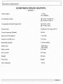
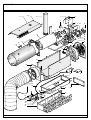
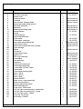
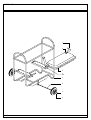
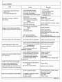
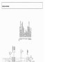
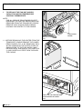
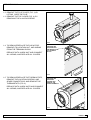
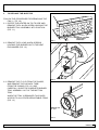
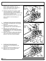
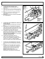
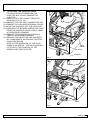
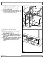
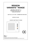
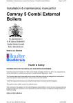
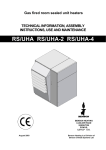
PORTABLE HEATER PARTS LIST AND SERVICE MANUAL
BENSON HEATING LTD
INTRODUCTION
The C.S.H heater is designed and manufactured within
the quality guidelines of ISO 9001
Care should be taken to ensure that the information used
from this manual is applicable to the model of heater.
This manual provides the necessary information for the
safe operation, cleaning, and servicing of the C.S.H.
Heater.
SAFETY INFORMATION FOR HEATER
OPERATION
HEALTH AND SAFETY AT WORK ACT 1974
Under section 6 of the Health & Safety at work act 1974
the manufacturer has taken reasonable and practical
steps to ensure that the Benson range of appliances are
safe and without risk when properly used.
These Heaters should therefore only be used in the
manner and purpose for which they were intended and in
accordance with the recommendations detailed herewith.
The Heaters have been designed, manufactured,
assembled, and inspected with safety in mind, there are
certain basic precautions which the user should be aware
of and the user is therefore strongly advised to read the
operating instructions before operating the Heater
This equipment should only be used by a competent
person who has read and understood the following
instructions
Do not use this equipment if you are ill feeling tired
or under the influence of alcohol or drugs.
WARNING
Keep animals and children away from heater NEVER
leave them alone when heater is in use
Never use the heater if highly flammable vapours are
present, or in a dUSty environment.
Never stack or lean objects on or against the heater
whilst in operation
Never restrict the air supply to the heater
Ensure the operating area is well ventilated restricted
combustion can cause carbon monoxide - concentrated
carbon monoxide kills
Never Operate the heater near vehicle exhaust fumes
Never fill the heater whilst it is hot or running
Always wear protective ciothing when filling heater
(Gloves Goggles etc)
Never smoke or allow naked light into the area when
refueling
Always mop up any spillage immediately
Never breathe any unbumt gas oil vapours
Contained within the text of this manual the words
CAUTION and WARNING are used to highlight certain
points.
Always ensure heater is standing on a firm level noncombustible surface
Never move the heater whilst it is in operation
CAUTION Is used when failure to adhere to the
instruction could result In premature failure or damage to
the heater.
WARNING is used when failure to heed or implement the
instruction can lead to component damage or risk of
personal injury.
WARNING Before carrying out any work on the heater
ensure that electrical supply is isolated 110 Volt heaters
piug into a standard 110 volt generator ensure flex and
plugs are undamaged. Uncoil extension leads fully
Never run leads through water or over sharp objects
Never carry or pUll heater by the electrical cable
Whilst every care is taken to ensure that the information
in this manual is correct Benson Heating accept no
liability for misuse or from any loss, damage, or injury
caused by errors in, or omissions from the information
supplied.
WARNING use of electrical equipment in damp or wet
conditions can be dangerous
Ensure that the sections on Heater Controls and
Heater Operation are read and understood before
operation of this equipment.
For further information contact and advice contact
Spares I Service Depts. at Knighton Powys
TELEPHONE 01547 528534 FAX 01547 520399
I
PAGE No2
~ECHNICAL
SPECIFICATION
CONFINED SPACE HEATER.
(DIESEL)
Heat Output
11 Kw
(37,500Btu)
Air Delivery (cold)
@ 7mtrs 0.202m 3/s
@ 14mtrs 0.185 m
Temperature Rise through Unit
@7mtrs 40°C
@ 14mtrs 30°C
Nozzle size
Danfoss 0.30 Usg x 60° H
Pump Pressure (Diesel)
90 Psi
Max Fuel Throughput
1.3ltrs/hr
Sound Level (D.b.a.)
70 D.b.a.
Electricity Supply
11 OVolt 150Hz
Motorsize
Start current
2550 Rpm
220 Watts
4.5 Amp
Run current
2.0 Amp
Weight
48 Kgs
FuelType
Diesel
Tank Capacity
16 Us
PAGE No 3
I
PARTS LIST
1A
1
2
3
5
4
6
7
11
10
8
17 18
17A
9
12
13
14
20
21
22
23
24
25
15
26
16
27
28
29
42
41
44
45
30
39
43
43A
31
32
31A
33
34
37
PAGE No 2
38
35
36
19
40
30
PARTS LIST
Item No
1
2
3
4
5
6
7
8
9
10
11
12
13
14
15
16
17
18
19
19A
20
21
22
23
24
25
26
27
28
29
30
31
32
33
34
35
36
37
38
39
40
41
42
43
43A
44
45
Parts Description
Top cover outer casing
Flue Pipe assembly
Burner cover
Pressure switch
Photocell
Allen screws - hexagon head
Burner assembly including base
Electrode assembly
Blast tube
Blast tube mounting collar
Burner Gasket
Nozzle
Heat exchanger
Heat shield assembly
Thermostat
Thermostat - reset type
Inlet valve solenoid assembly
Quick release valve
Filter bowl complete with filter cartridge
Filter cartridge
Elbow
Fuel pump
Quick release valve
Ignition unit
Fan cover assembly
Control Box
Fan and motor
Capacitor
Outer cover base panel
Outlet spigot assembly
3 core cable 110 Volt Yellow
Thermostat
Thermostat mounting plate
Neon - Yellow
Neon - Green
Neon - Red
Switch ON/OFF
Base cover - outer power inlet
Base mounting frame
Burner casing Lower panel
Base blanking panel
Front cover - Lower inner
110 Volt 3 pin connection plug - transformer
110 Volt 3 pin connection plug - heater
110 Volt 3 pin socket - heater
Terry clip - Air ducting
Air ducting - Flexible
No Off
1
1
1
1
1
2
1
1
1
1
1
1
1
1
1
1
1
1
1
1
3
1
1
1
1
1
1
1
1
1
1
1
1
1
1
1
1
1
1
1
1
1
1
1
1
1
1
Part No
21-30-011
21-30-057
E8010810000100
E8010610000000
E8040017320000
E8020003000001
E8000400100400
E8000100500101
21-30-061
21-30-001
28-16-049
28-16-050
E80010403110300
E8030120220200
E9030310110100
E8030010420100
E8030110430100
E8010203210000
21-30-012
E8010511003500
28-09-070
21-30-010
21-30-022
28-02-184
28-16-047
21-30-030
28-50-022
28-50-021
28-50-020
28-40-127
21-30-032
21-30-023
21-30-024
21-30-031
28-06-044
28-06-039
28-06-035
28-01-079
28-01-077
PAGE No 3
PARTS LIST
1
2
3
4
4A
5
6
7
8
PAGE No 4
PARTS LIST
Item No
1
2
3
4
5
6
7
8
Parts Description
Fuel pipes
Fuel Elbows
Fuel tank
Heater mounts
Frame
Spindle
Locking dome - wheel
Wheel
No Off
2
2
1
2
1
1
2
2
Part No
28-08-009
29-00-258
21-30-071
21-30-070
21-30-045
21-30-067
A30-01-030
A30-01-002
PAGE No 5
I
INSTALLATION AND CONTROLS
1 MOBILE HEATERS FUEL SUPPLY
HEATER CONTROLS
All Mobile Heaters are set to operate on a two-pipe
system.
In order to promote trouble free operation it is
necessary that the oil does not fall below the cold
filter plugging point with class D fuel this is -4°C
Summer grade and -12°C Winter grade
All pipe work and fittings must be sealed so as to prevent
the ingress of air.
1. THREE POSITION SWITCH ( HEAT I OFFI VENT)
110 Volt supply indicated by a green Neon light on
panel
(Heat position) Operates the bumer control circuit to the
control box
(Off position) Breaks the bumer control circuit to the
control box
(Vent position) operates the fan only for ventilation
purposes
ELECTRICAL SUPPLY
2. THERMOSTAT CONTROL KNOB
110 Volt electrical supply connection is made to the
heater via the generator
THERMOSTAT CONNECTION
A temperature control thermostat located within the
heater air discharge spigot can be adjusted to the
required temperature via the dial located on the heater
control panel.
FLUE INSTALLATION
C.S.H. Mobile Heaters are dispatched with the requisite
stack spigot and flue pipe.
It is recommended that O.5mm stainless steel flue be
fitted
In general each indirect heater should have its own flue,
which should terminate approximately 500mm above the
heater.
When siting the heater and flue the proximity of other
buildings and obstacles should be considered.
FLEXIBLE DUCTING
IMPORTANT The flexible ducting supplied with the
heater should be fitted with the direction of flow which is
indicated by an arrow on the duct pointing away from the
heater
It should be secured to the outlet spigot with the pull strap
provided.
Enables the temperature in the air ducting to be regulated
to the desired temperature. The orange neon light on the
panel (bumer run light) will be on until the desired
temperature is reached and the burner switches off.
3. CONTROL BOX
Situated on the control panel, monitors the combustion
process of the heater to ensure that all components are
operating correctly, it will shut down the heater if a fault
occurs, a red light showing in the center of the Satronic
Control Box will flash periodically as the box monitors the
burner operation
If this light is permanently on it indicates that there is a
fault with the operation of the bumer and it has gone to
lockout the red button should be pressed (LOCKOUT
RESET)
See fault-finding chart in bumer manual.
4. OVERHEAT THERMOSTAT
Located on the heat shield is a safety overheat
thermostat, this thermostat will operate if the combustion
chamber becomes to hot in the event of a fan failure or
restricted air flow.
The thermostat when it operates will immediately shut
down the bumer and a red ** neon light will be
illuminated on the control panel.
The thermostat can be reset by pushing the plastic reset
button located on the top cover, the red** neon will go
out when reset.
IT MUST BE MANUALLY RESET AND THE CAUSE OF
THE OVERHEAT SHOULD BE INVESTIGATED
The above red ** neon is dual purpose see
also operating instructions.
I
PAGENoB
~PERATING
INSTRUCTIONS
COMMISSIONING PROCEDURE
The heater should be positioned on firm ground ensuring
that the air intake is clear of vehicle exhaust fumes and
other hazardous conditions:
Connect the 110 Volt supply cable from the generator to
the heater.
The green neon will be illuminated.
Ensure fuel supply is clean.
Connect the ducting to the duct spigot on the heater
using pull strap provided ensuring the correct direction of
flow
Fit the flue pipe to the top of the heater
1 Ensure heater has fuel supply.
2 Ensure thermostat is at desired ternperature
3 Connect electrical supply
4 Switch to heat position
5 Ensure lockout button on control box is reset, burner
sequence should start immediately
6 Run heater for approx.15 minutes
7 Switch heater to OFF check operation of overrun
thermostat
8 Restart heater to check correct operation of thermostat
MAINTENANCE INSTRUCTIONS
To VENT only, put three position switch to vent position,
the fan only will operate
WARNING
Before carrying out any maintenance work on the heater
ensure that electrical supply is isolated and fuel supply
disconnected.
To HEAT, put three position switch in heat position
FUEL SYSTEM
The main fan will run and the red** neon on the controi
panel will illuminate indicating that the pre heater fitted to
the burner is operating and pre heating the fuel prior to
the burner start .
FILTERS
The heater is now ready for use
NOTE the red** neon will indicate pre heat at initial
start up only, if the neon is illuminated at any other
time the heater is at overheat.
After approximately 150 seconds the red" neon will go
out and the bumer will fire, the orange neon on the
control panel will illuminate.
The heater will now operate controlled by the thermostat.
To STOP put three position switch to off position.
The burner ON orange neon will go off, and the main fan
will continue to run for a further 5 minutes to sufficiently
cool the combustion chamber the fan will then switch off .
Only then rnay the electrical supply be safely
disconnected.
WARNING
Failure to cool the heater sufficiently will cause damage to
the combustion chamber and lead to nuisance overheat
lockout problems.
All heaters are supplied with a filter located in the fuel line
the paper filter cartridge cannot be cleaned and must be
totally replaced during servicing or when contaminated,
FUEL PUMP PRESSURE ADJUSTMENT
Ensure electrical supply is off and disconnected.
Remove rear lower base cover on heater
Remove vent plug located on the end of the brass
extension pipe on the pump body (in the center when
viewed from rear of heater)
Fit pressure gauge to brass extension
Re connect electrical supply
Switch Burner ON observe reading on gauge
Set pressure to (90 psi) diesel only
If adjustment is required situated above the fuel inlet
connection (left side when viewed from rear) is a screw
and locknut undo the locknut insert PhiJlips screw driver
into the screw head adjuster, turn clockwise to increase
anticlockwise to decrease the pressure.
When the pressure is correctly set tighten locknut
disconnect the electrical supply, remove gauge and
replace bleed screw and ensure it is tightly located
Replace rear cover
PAGE Nog
I
[ MAINTENANCE
PHOTOCELL
BURNER MAINTENANCE
Burner Maintenance should only be carried out by
competent personnel
and will require the complete rernoval of the Burner from
the combustion chamber
BURNER ASSEMBLY
see pages 15 & 16 for further detail
Disconnect the electrical supply to the heater
Disconnect fuel supply
Carefully roll heater on to its side and remove the 4 x M5
Screws from the base return unit to upright position
Remove top cover of heater 6 X M5 Screws
Remove bottom rear panel 4 x M5 Screws
Remove fan assernbly Screws 4 X M5 (lower two can be
accessed by inserting screw driver through the holes in
the base of the heater)
and lift fan assembly out
Disconnect the wires from the block at the rear of the
burner head
Remove the thermostat capillary from the securing clips
in nose cone and lower into the heater base through the
hole provided.
Remove the blanking panel 4 X M5 Screws
Rernove the two screws securing the burner to the
combustion chamber flange
The burner, blast tube, and control base can now be
cornpletely removed through the rear of the heater.
Maintenance of the Burner is detailed in the Installation
and Service Manual supplied separately.
Clean soot or carbon deposits from diffuser, end ring, or
electrode tips
Clean and inspect electrodes for cracks replace if
necessary
Reset electrodes to dimensions shown in Burner manual
do not over tighten securing screw
A new Nozzle should be fitted every 12months or if
existing nozzle is damaged or worn.
Reassemble taking care that all parts are clean and dry.
Ensure fuel pipe is kept free from dirt whilst burner head
is dismantled
I
PAGE No 10
Ensure that the photocell is clean (wipe clean with a soft
cloth)
CONTROL BOX
The control box cannot be repaired if the box is faulty it
should be replaced with a new box
WARNING
The control box should not be reset more than twice
before the fault is located and corrected, or any
surplus oil emitted into the chamber has been
mopped out through the burner entrance.
HEAT EXCHANGER REMOVAL
Remove complete burner assernbly
If required the combustion chamber can be removed by
bending up the chamber retaining clips and sliding the
chamber towards the rear of the heater
Chamber can now be cleaned by tapping the outside of
the chamber with a hide hammer or piece of wood. Care
should be taken not to damage the burner flange.
Rernove any loose soot, carbon through the draught tube
aperture or the flue stack spigot
Re assemble in reverse order of above instruction.
I
FAULT FINDING
Fault
Heater Fails to start when heat is
switched ON
Thermostat calling for heat
Red light showing on satronic
control box
Heater runs for short period does
hot light control box goes to lockout
Cause
(a) No Electricity Supply
(b) Switch fan to manual
(c) Faulty Thermostat
(d) Overheat thermostat tripped
(a) No fuel
(b) Air lock in fuel supply
(c) Photocell not detecting
flame
(d) Faulty electrodes
(e) Faulty control box
(afPhotocell notaetecting
flame
(b) No fuel
(c) Ignition failure
(d) Fuel pump failure
(e) Faulty solenoid valve
Red neon light on fan not working
(a) Heater gone to overheat
(a) Photocell not detecting light
(b) Faulty photocell connection
Heater attempts to light up but
in control box
Burner Control box goes to lockout
(c) Faulty control box
(d) Air pressure switch not
bperating solenoid
(a) Air control incorrectly set
(b) Nozzle loose or incorrect
Heater runs but emits black smoke
(c) Incorrect fuel pressure
rom stack box
(d) Exhaust stack restricted
(e) Excess carbon in the
~raught tube
Heater runs but fan overrun does
hot work when switched off******
n order to check this fault the
lleater should be run to ensure the
k;ombustion chamber is hot enough
(a) Loose wire on the overrun
device
(b) Overrun device faulty
(a) Air in the fuel supply
Heater runs but flame is intermitten
(b) Heater running out of fuel
(c) Filter blocked
(d) Dirty nozzle
Remedy
Check Supply
Fan runs supply correct
Check thennostat
Reset red button on trip,
Investigate cause
Check fuel
Bleed Fuel system
Check & clean Photocell
Check electrode for cracks, check
ignition leads
~heck photocell
bheck fuel supply
bheck ignition leads
bheck electrodes are clean & gap
~et correctly
~heck solenoid valve
bheck electrical connection to valve
Reset overheat thermostat
~heck photocell operation
/:heck wiring connection
bhange control box
bheck switch
Reset air control
Check nozzle
Check fuel pressure
Clear stack
Clean carbon from draught tUbe
Check wiring
Replace overrun device
Check fuel pipe for cracks, check
pipe unions are tight
Check fuel supply
Clean filter
Check nozzle
PAGENo11
I\)
0
....
Z
m
~
G')
"
t
X1
M2
w 1---'7""'H-r-;H>-J
zl--....J
r-----------------------r,~~~~;rL~r,~~~
L-----------------------~_,L~~~~~L;J_,L~~
•
110V·50Hz
MAINS
INLET
L1
M1
X1
SW
M1
M2
L1
L2
L3
V1
P
PH
TS
PT
T
PA
TSO
TSR
LK1
MIS
KEY·
• SATRONIC DK0972 BASE
• SELECTOR SWITCH (HEAT/OFFNEND
• BURNER MOTOR
•AIR CIRCULATOR MOTOR (FAN)
• OVER HEAT/STAND BY NEON (RED)
• BURNER RUN (ORANGE)
• POWER ON (GREEN)
• OIL VALVE
·OILPUMP
• OIL PRE·HEATER
• THERMOSTAT
• PHOTOCELL
• IGNITION TRANSFORMER
• AIR PRESSURE SWITCH
• OVERHEAT THERMOSTAT cJw RESET
• RUN·ON THERMOSTAT
• BURNER LINK
• MAINS INLET SOCKET
:E
3:
~
C
»
G)
G)
Z
~
SERVICE MANUAL
1
TO REPLACE THE FAN UNIT AND/OR
CAPACITOR AND/OR TEMPERATURE
CONTROL THERMOSTATS
NOTE:
FOR ALL SERVICE PROCEDURES EXCEPT
PRESSURE TESTING THE HEATER MUST BE
REMOVED FROM THE TRANSPORT CRADLE.
REMOVE THE 4 PHILIPS HEAD SCREWS
HOLDING THE HEATER TO THE CRADLE.
4 PHILIPS HEAD
SCREWS
FIG. 1
1:1 BEFORE REMOVING THE HEATER FROM THE
TRANSPORT CRADLE REMOVE THE LOWER
REAR COVERS (FIG. 2), BY REMOVING THE 4
ALLEN SCREWS ON THE OUTER COVER TO
GAIN ACCESS TO THE FUEL SUPPLY AND
RETURN PIPES, AND UNCLIP THE PIPES (FIG.
3), AND CAREFULLY FEED THEM THROUGH
THE CASING.
FIG. 2
UNCLIP THE FUEL PIPES AND FEED
THEM THROUGH THE CASING
FIG. 3
PAGE No 6
SERVICE MANUAL
1:2 REMOVE THE FLUE COVER (FIG. 4) BY
LIFTING OVER THE FLUE
1:3 REMOVE THE TOP COVER (FIG. 4), BY
REMOVING THE 4 ALLEN SCREWS
FIG. 4
1:4 TO REMOVE/REPLACE THE CAPACITOR,
REMOVE ITS LOCATION NUT, AND WIRING
FROM THE TERMINAL BLOCK.
REPLACE WITH A NEW UNIT AND CONNECT
ALL WIRING, AND REPLACE ALL COVERS.
UNSCREW THE
RETAINING NUT
AND WIRING FROM
THE TERMINAL
BLOCK
FIG. 5
1:5 TO REMOVE/REPLACE THE THERMOSTATS,
REMOVE THE LOCATION SCREWS, AND
SPADE CONNECTORS, AND REMOVE THE
THERMOSTATS (FIG. 6).
UNSCREW THE
RETAINING
SCREWS AND
REMOVE THE
SPADE TERMINALS
REPLACE WITH A NEW UNITS AND CONNECT
ALL WIRING, AND REPLACE ALL COVERS.
FIG. 6
PAGE No 7
SERVICE MANUAL
1:6 TIP THE HEATER ON ITS SIDE TO EXPOSE
THE 2 LOWER FAN RETAINING SCREWS, AND
REMOVE THE TWO SCREWS (FIG. 7)
FIG. 7
1:7 PLACE THE HEATER IN ITS NORMAL
POSITION AND REMOVE THE REMAINING 2
ALLEN SCREW (FIG. 8)
FIG. 8
1:8 UNPLUG THE MULTI WAY CONNECTOR AND
THE 4 THERMOSTAT LEADS (2 ORANGE 2
YELLOW)
1:9 UNPLUG THE PHOTOCELL (FIG. 9)
FIG. 9
1:10 CAREFULLY REMOVE THE FAN AND COVER
(FIG. 10) ASSEMBLY FROM THE CASING, AND
THEN REMOVE THE FAN FROM THE REAR
SLOTTED COVER BY REMOVING THE 4
ALLEN SCREWS.
1:11 REPLACE WITH A NEW UNIT.
1:12 RE ASSEMBLE BY REVERSING THE STRIP
DOWN PROCEDURE
(NOTE WHEN REPLACING THE PHOTOCELL
UNIT- IT ONLY FITS ONE WAY, DO NOT USE
EXCESSIVE FORCE WHEN REPLACING - IT
COULD BE DAMAGED)
FIG. 10
PAGE No 8
SERVICE MANUAL
2
TO REPLACE THE INJECTOR
FOLLOW THE PROCEDURE FOR REMOVING THE
FAN (1:1 TO 1:9)
2:1 ROTATE THE HEATER ON TO ITS SIDE AND
REMOVE THE 4 ALLEN SCREW HOLDING THE
BURNER TRAY ASSEMBLY INTO POSITION
(FIG. 11).
FIG. 11
REMOVE 4 SCREWS
FROM CASING
UNDERSIDE
2:2 REMOVE THE 2 LONG ALLEN SCREWS
HOLDING THE BURNER ON TO THE HEAT
EXCHANGER (FIG. 12).
FIG. 12
2:3 REMOVE THE ‘P’ CLIP FROM THE GUARD,
AND REMOVE THE CAPILARY TUBE.
FROM THE CASING (FIG. 13), AND
CAREFULLY SLIDE THE COMPLETE BURNER
TRAY ASSEMBLY OUT OF THE BOTTOM
TRAY.
WHEN THE TRAY IS REMOVED THIS GIVES
ACCESS TO ALL OTHER SERVICEABLE ITEMS
(FIG. 13)
REMOVE THE
‘P’ CLIP
FIG. 13
PAGE No 9
SERVICE MANUAL
2:3 REMOVE THE 3 SCREWS HOLDING THE
BLAST TUBE IN POSITION. (FIG. 14)
NOTE: THE BURNER TRAY PRESSING IS
SHOWN CUT AWAY FOR CLARITY
BLAST RING
&3
RETAINING
SCREWS
INJECTOR
14MM
LOCK
SPANNER
FLATS
2:4 REMOVE THE INJECTOR, USING A 16MM
LOCK SPANNER AND A 14MM SPANNER.
CARE MUST BE TAKEN NOT TO DAMAGE THE
IGNITION ELECTRODES WHEN
REMOVINGAND REPLACING THE INJECTOR.
REPLACEMENT IS THE REVERSAL OF
REMOVAL
FIG. 14
3
TO REPLACE THE IGNITION ELECTRODES
FOLLOW STEPS FOR REMOVING THE FAN AND
INJECTOR
3:1 REMOVE THE BURNER COVER, BY
UNSCREWING THE 4 ALLEN SCREWS (FIG.
14)
3:2 REMOVE THE COVER RING (A), BY
UNSCREWING THE SINGLE BUTTON HEAD
ALLEN SCREW (FIG. 15), TO GAIN ACCESS TO
THE INJECTOR.
3:3 UNCLIP THE IGNITION LEADS AND REMOVE
THE ALLEN SCREW, AND REMOVE AND
REPLACE THE ELECTRODE ASSEMBLY.
ELECTRODE ASSY.
& ALLEN SCREW
IGNIGNITION
LEADS
COVER RING
& ALLEN
SCREW
FIG. 15
BLAST
RING
BURNER
COVER
IGNITION
LEADS
ALLEN
SCREWS
4
TO REPLACE THE IGNITION UNIT
FOLLOW STEPS FOR REMOVING THE
INJECTOR
4:1 UNPLUG THE IGNITION LEADS (FIG. 16)
4:2 REMOVE THE 2 ALLEN SCREWS AND
REPLACE WITH A NEW UNIT
FIG. 16
PAGE No 10
SERVICE MANUAL
5
TO REPLACE THE CONTROL BOX
FOLLOW STEPS FOR REMOVING THE
INJECTOR
5:1 TAKE OFF THE 2 ALLEN SCREWS HOLDING
THE CONTROL BOX ASSY TO THE BASE (FIG.
17)
5:2 REMOVE THE SINGLE SCREW RETAINING
THE CONTROL BOX TO THE BASE
MOULDING
5:3 REPLACE CONTROL BOX AND RE-ASSEMBLE
ALL COMPONENTS
2 ALLEN
SCREWS
RETAINING
CONTROL
BOX ASSY TO
BASE
FIG. 17
SINGLE SCREW
RETAINING
CONTROL BOX
TO BASE
MOULDING
6
TO REPLACE THE THERMOSTAT, NEONS AND
ON/OFF SWITCH
FOLLOW STEPS FOR REMOVING CONTROL
BOX
6:1 TO REMOVE THE THERMOSTAT, REMOVE
THE CONTROL KNOB, AND UNSCREW THE 2
RETAINING SCREWS. REPLACE WITH A NEW
UNIT, AND REFIT ALL ITEMS (FIG. 18).
6:2 TO REMOVE AND REPLACE A NEON.
UNSCREW YTHE LEADS AT THE CONNECTOR
BLOCK (THEY ARE FLYING LEADS), NOTING
THEIR TERMINAL NUMBERS.
UNSCREW THE RETAINING NUT, WITHDRAW
THE NEON, AND REPLACE.
6:3 TO REPLACE THE ON/OFF SWITCH.
UNPLUG ALL WIRES FROM THE SWITCH,
NOTING THEIR TERMINAL NUMBERS, UNCLIP
THE SWITCH, AND FIT A REPLACEMENT.
REFIT ALL WIRES, AND OTHER COMPONENTS.
FIG. 18
7
TO REPLACE THE POWER INPUT SOCKET
FOLLOW STEPS FOR REMOVING CONTROL
BOX
7:1 TO REMOVE THE POWER INPUT SOCKET,
NSCREW THE 3 POWER RING TERMINALS/
WIRES FROM THE SOCKET, AND THEN
UNSCREW THE 4 NUTS HOLDING THE
SOCKET IN PLACE (FIG. 19).
REPLACE WITH A NEW ITEM, REFIT
REVERSING THE REMOVAL PROCEDURE.
FIG. 19
PAGE No 11
SERVICE MANUAL
8
TO REPLACE THE PRESSURE SWITCH
FOLLOW STEPS FOR REMOVING THE
INJECTOR, BUT DO NOT REMOVE THE
INJECTOR.
8:1 TO REMOVE THE PRESSURE SWITCH,
REMOVE THE NEGATIVE AND POSITIVE
PRESSURE TUBES FROM THE SWITCH NOTING THAT THE POSITIVE TUBE GOES TO
THE REAR INLET ON THE SWITCH (FIG. 20).
8:2 UNSCREW THE SINGLE SCREW AND
REMOVE THE SWITCH SO THAT THE COVER
CAN BE REMOVED.
8:3 REMOVE THE COVER, AND REMOVE THE
POWER LEADS - NOTING THAT BROWN
GOES TO COMMON AND BLUE TO
‘NORMALLY OPEN’ (NO ON SWITCH).
3:4 REPLACE ALL COMPONENTS - REVERSING
THE STRIP DOWN PROCEDURE.
NEGATIVE
TUBE
BROWN
TO
COMMON
REAR
INLET
FRONT
INLET
POSITIVE
TUBE GOES TO
REAR INLET
FIG. 20
9
9:1
9:2
9:3
9:4
9:5
TO REPLACE THE SOLENOID
FOLLOW STEPS FOR REMOVING THE
INJECTOR, BUT DO NOT REMOVE THE
INJECTOR.
UNPLUG THE 3 WAY SOCKET FROM THE
SOLENOID (FIG. 21).
REMOVE THE FUEL INLET CONNECTOR UNIT
REMOVE THE SOLENOID RETAINING CIRCLIP
SLIDE THE SOLENOID OFF THE FUEL INLET
REPLACE THE DEFECTIVE UNIT AND REFIT
ALL COMPONENTS, REVERSING THE STRIP
DOWN PROCEDURE
FIG. 21
PAGE No 12
BLUE
TO N.O.
NEGATIVETUBE
GOES TO
FRONT INLET
SERVICE MANUAL
10 TO REPLACE THE SOLENOID VALVE
FOLLOW STEPS FOR REMOVING THE
INJECTOR, BUT DO NOT REMOVE THE
INJECTOR.
10:1 UNPLUG THE 3 WAY SOCKET FROM THE
SOLENOID (FIG. 22, 23)
10:2 REMOVE THE FUEL INLET CONNECTOR UNIT
10:3 REMOVE THE SOLENOID RETAINING CIRCLIP
10:4 SLIDE THE SOLENOID OFF THE FUEL INLET
10:5 UNFASTEN THE BURNER NOZZLE FUEL INLET
FROM THE SOLENOID VALVE USING A 10MM
AF OPEN ENDED SPANNER
10:6 REMOVE THE SOLENOID VALVE USING A
12MM AF OPEN ENDED SPANNER
10:5 REPLACE THE DEFECTIVE UNIT AND REFIT
ALL COMPONENTS, REVERSING THE STRIP
DOWN PROCEDURE
NOTE ON THE UNDERSIDE OF THE VALVE
THERE IS AN ARROW - THE VALVE MUST BE
FITTED WITH THIS POINTING TO THE
NOZZLE INJECTOR FUEL PIPE
3 WAY
SOCKET
CIRCLIP
SOLENOID
FIG. 22
VALVE
FIG. 23
PAGE No 13
SERVICE MANUAL
11
TO REPLACE THE FUEL PUMP
NOTE THIS IS A NON SERVICEABLE ITEM
AND MUST BE REPLACED AS A UNIT
FOLLOW STEPS FOR REMOVING THE
SOLENOID AND VALVE
11:1 TO REMOVE THE FUEL PUMP, UNSCREW THE
2 ALLEN SCREWS FASTENING THE PUMP TO
ITS MOUNTING BRACKET (FIG. 24).
2 ALLEN SCREWS
MOUNTING
BRACKET
FUEL PUMP
FIG. 24
12 TO REPLACE THE FUEL FILTER.
NOTE:
THE HEATER CAN REMAIN IN ITS TRANSPORT
CRADLE FOR THIS OPERATION.
12:1 REMOVE BOTH REAR INNER AND OUTER
BOTTOM PANELS (FIG. 25).
12:2 UNSCREW THE FILTER BOWL, REMOVE THE
FILTER, CLEAN THE BOWL IF DIRTY AND FIT A
NEW FILTER.
12:3 REFIT THE BOWL/FILTER ASSEMBLY, ENSURE
IT IS ADEQUATELY TIGHTENED TO AVOID
LEAKS, AND REPLACE BOTH BOTTOM
PANELS.
FIG. 25
PAGE No 14
PRESSURE
TESTING ‘T’
SERVICE MANUAL
13 TO TEST FUEL PUMP PRESSURE
NOTE: FOR THIS OPERATION THE HEATER MUST
BE ON ITS CRADLE WITH THE FUEL LINES
CONNECTED.
13:1 REMOVE BOTH REAR INNER AND OUTER
BOTTOM PANELS.
13:2 UNSCREW AND REMOVE THE PRESSURE
TESTING POINT BLANKING PLUG (FIG. 26)
13:3 CONNECT THE FUEL FEED PIPES
13:4 SCREW IN THE PRESSURE TESTING GAUGE
13:5 TO ADJUST THE PRESSURE UNLOCK THE
LOCK NUT (A) AND ADJUST THE SCREW (B) IN
OR OUT TO ACHIEVE THE REQUIRED
PRESSURE. THE CORRECT PRESSURE 90
PSI.
13:6 WHEN THE PRESSURE IS CORRECTLY SET
RE -FIT ALL COMPONENTS
ADJUSTING
SCREW (B)
LOCK NUT
(A)
PRESSURE
GAUGE
BLANKING
PLUG
FIG. 26
PAGE No 15
BENSON HEATING LTD
LUDLOW ROAD
KNIGHTON
POWYS
LD7 1LP
TELEPHONE 01547 528534
FACIMILE
01547 520399
email [email protected]
web
www.bensonheating.com