1
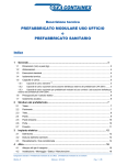
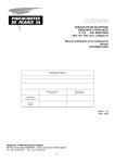
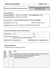
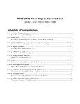
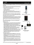
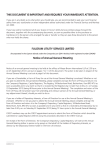
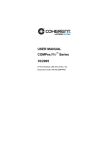
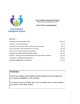
Technical Service Bulletin 030614
Technical Service Bulletin 030614
IOT High Voltage Troubleshooting with Hipot Test Set
Procedure 030614: IOT High Voltage Troubleshooting with Hipot Test Set
Applicability
IOX, DCX, and Advantage transmitters.
Prerequisites
Knowledge of high voltage safety procedures. Knowledge of First Aid
procedures. Second person must be present at all times.
Equipment Required
Hipot test set. Comark rental Spellman SL60N300 unit or otherwise.
Comments
When high voltage will not turn on / stay on due to motorized breaker trips and/or
crowbar alarms.
WARNING: The procedure described in this document involves potentially dangerous
high voltages. While the high pot test set operates on the principal of high voltage - low
current, to maximize personnel safety, it is nevertheless critical that proper high voltage
safety procedures be employed at all times. Do not attempt this procedure without a
second person present. Do not attempt this procedure while tired or otherwise not fully
alert. Always use the transmitter grounding hook to properly ground all high voltage
circuits before attempting to touch them. Consult Service Bulletin 940911 for information
on proper high voltage safety procedures.
To assemble rental Spellman SL60N300 high pot test set.
Comark has several Spellman SL60N300 high pot test sets for rent. This section describes how
to unpack the rental unit and prepare it for service.
1. Remove front and rear covers from reinforced
shipping case.
2. Connect green / yellow ground wire to ground
stud at rear of unit.
3. Connect insulated HV lead to test set and thread
connector shell to chassis connector (see
photo). If banana plug at end of HV lead will not
seat fully inside unit (threads will not engage),
remove HV lead, check for straightness, lightly
bend cable to maximize straightness, and reattempt to establish connection.
4. Connect modular AC cord to rear of unit.
REV B2 - 13 February 2004
1
Technical Service Bulletin 030614
To test IOT and high voltage compartment after HV isolate relay.
This section describes how to test the high voltage standoff capabilities of the high voltage
circuit from the HV isolate relay to the IOT. This test is performed when the transmitter is able
to withstand high voltage in HV ISOLATED mode, but crowbars immediately while in HV
CONNECTED mode (thereby suggesting an HV flashover in the high voltage circuit occurring
after the HV isolate relay).
NOTE: IOX and DCX users may find it useful to consult drawing 451890 Schematic HV
Compartment (HPA Manual Chapter 12). Advantage users may find it useful to consult
drawing 46744001 pgs 5-6 Interconnect, Advantage (Service Manual Chapter 4.2).
1. Place transmitter in HV ISOLATED mode by actuating high voltage isolate relay from
HPA control panel.
NOTE: Certain IOX and DCX transmitters feature mechanically latching high voltage
isolate relays. Others have non-latching relays that require a continual voltage from the
HPA controller to remain in the ISOLATED state. These non-latching relays will relax to
the CONNECTED position when AC power is removed from the transmitter. In such
cases, it is necessary to physically remove the red HV wire lead from the HV isolate relay
to achieve the desired isolated condition.
2. Turn transmitter completely off and disconnect all mains power to transmitter.
3. Gain access to HPA high voltage compartment via key interlock system.
4. Discharge all high voltage circuits in high voltage compartment with grounding hook.
5. Visually inspect high voltage (HV) compartment for any signs of carbon marks, pinholes
or damage to red jacket of HV wires, signs of corrosion in any plastic or Teflon materials.
These are all indications of a possible high voltage standoff problem.
6. Disconnect red HV wire from grounding switch to filament / bias / ion supply case.
Reroute disconnected wire to maintain it far from circuit under test.
7. Connect HV+ / GND lead from hipot test set to grounded frame of transmitter. Be sure
to connect to a bare (non-painted) metal surface.
8. Connect HV- lead from hipot test set to filament / bias / ion supply case.
WARNING: Verify that high voltage isolate relay is indeed in the isolated (open) position
and that no connection exists between the portion of the high voltage circuit under test
and the high voltage beam supply. Otherwise, it is possible to charge the beam supply
filter capacitors with the high pot test set, thereby creating a potentially lethal situation.
REV B2 - 13 February 2004
2
Technical Service Bulletin 030614
Photo of high pot test set HV- lead to FBI supply body.
The dangling high voltage wire in the upper right of photo is the
disconnected wire from the ground switch, as described above.
It is temporarily supported by the HV compartment door locking
mechanism.
9. Turn hipot test set voltage adjustment to zero volts.
10. Connect AC mains voltage to hipot test set.
11. Turn off all lights and any sources of ambient noise.
12. Activate hipot test set and apply high voltage to transmitter, increasing slowly from zero
volts up to maximum of 40 kV. Listen carefully for any voltage breakdowns indicated by
audible hissing, popping, crackling, or other noises. Visually inspect all high voltage
circuits for glowing corona discharges.
Adjust current limit adjustment (SL60N300…next to current meter), as necessary, to
prevent hipot test from entering current-limited mode (CURRENT display lights).
WARNING: Do not place ears or eyes close to high voltage compartment in an attempt to
detect voltage breakdowns. Always maintain all body parts at least one foot from front of
open high voltage compartment.
13. If corona or partial breakdowns are discovered, turn off and fully discharge hipot test set
and attempt to eliminate cause of breakdown by increasing standoff distances (where
possible), rounding off any sharp corners with a fine-grain sandpaper or file (where
REV B2 - 13 February 2004
3
Technical Service Bulletin 030614
applicable), or cleaning any localized dust accumulations with denatured alcohol and a
clean rag.
NOTE: Localized dust accumulations on high voltage wires and/or the walls of the high
voltage compartment (dust shadows) are signs of enhanced voltage stress in these
areas. (see photo). When such an accumulation is discovered, it should be removed
with a cleaning rag and the high voltage wires re-routed with greater standoff distances
(when possible) to prevent a reoccurrence.
The high voltage wire on the left was moved to expose a dust
shadow on the wall of the high voltage compartment. A
fingerprint smudge in the center of the smudge helps verify its
presence.
14. If complete HV breakdown is observed (bright flash and/or hipot trips), attempt to locate
source of breakdown by progressively disconnecting portions of high voltage circuit and
repeating hipot test. For example, repeat test after having removed socketed tube
(where applicable), repeat test after having disconnected IOT junction box connections,
repeat test after having disconnected HV filament, grid, and ion wires from filament / bias
/ ion supply output, repeat test after having disconnected floating 120 VAC feed from HV
isolation transformer to FBI supply, etc.
REV B2 - 13 February 2004
4
Technical Service Bulletin 030614
NOTE: A special adapter that allows simultaneous
connection to all IOT leads (cathode, filaments, grid, and
ion) is supplied with the Thales rental hipot test set.
(photo at right).
15. Locate source of breakdown and remedy and / or replace damaged components.
16. Restore original high voltage circuit connections and close high voltage compartment.
17. Procedure complete.
To test high voltage circuit from crowbar to HV isolate relay.
This section describes how to test the high voltage standoff capabilities of the high voltage
circuit from the crowbar to the HV isolate relay. This test is performed when the transmitter is
not able to withstand high voltage in HV ISOLATED mode, but IS able to withstand high voltage
when J3 (HV input to crowbar) is disconnected, and more basic troubleshooting strategies have
failed (i.e. replace/troubleshoot crowbar assembly).
NOTE: IOX and DCX users may find it useful to consult drawing 451890 Schematic HV
Compartment (HPA Manual Chapter 12). Advantage users may find it useful to consult
drawing 46744001 pgs 5-6 Interconnect, Advantage (Service Manual Chapter 4.2).
NOTE: For more information on crowbar troubleshooting, please consult Comark
document 46744354 Troubleshooting Procedure, Thyratron Crowbar.
1. Place transmitter in HV ISOLATED mode by actuating high voltage isolate relay from
HPA control panel.
NOTE: Certain IOX and DCX transmitters feature mechanically latching high voltage
isolate relays. Others have non-latching relays that require a continual voltage from the
HPA controller to remain in the ISOLATED state. These non-latching relays will relax to
the CONNECTED position when AC power is removed from the transmitter. In such
cases, it is necessary to physically remove the red HV wire lead from the HV isolate relay
to achieve the desired isolated condition.
2. Turn transmitter completely off and disconnect all mains power to transmitter.
REV B2 - 13 February 2004
5
Technical Service Bulletin 030614
3. Gain access to HPA high voltage compartment via key interlock system.
4. Discharge all high voltage circuits in high voltage compartment with grounding hook.
5. Visually inspect high voltage (HV) compartment for any signs of carbon marks, pinholes
or damage to red jacket of HV wires, signs of corrosion in any plastic or Teflon materials.
These are all indications of a possible high voltage standoff problem.
6. Disconnect red HV wire from grounding switch to white high voltage capacitor on wall of
high voltage compartment. Reroute disconnected wire to maintain it far from circuit
under test.
7. Disconnect J3 from crowbar HV (upper) section. Reroute disconnected wire to maintain
it permanently grounded and far from circuit under test.
8. Connect HV+ / GND lead from hipot test set to grounded frame of transmitter. Be sure
to connect to a bare (non-painted) metal surface.
9. Connect HV- lead from hipot test set to connection stud of white high voltage capacitor.
WARNING: Verify that connection J3 is indeed broken at the crowbar and that no
connection exists between the portion of the high voltage circuit under test and the high
voltage beam supply. Otherwise, it is possible to charge the beam supply filter capacitors
with the high pot test set, thereby creating a potentially lethal situation.
10. Turn hipot test set voltage adjustment to zero volts.
11. Connect AC mains voltage to hipot test set.
12. Turn off all lights and any sources of ambient noise.
13. Activate hipot test set and apply high voltage to transmitter, increasing slowly from zero
volts up to maximum of 40 kV. Listen carefully for any voltage breakdowns indicated by
audible hissing, popping, crackling, or other noises. Visually inspect all high voltage
circuits for glowing corona discharges.
Adjust current limit adjustment (SL60N300…next to current meter), as necessary, to
prevent hipot test from entering current-limited mode (CURRENT display lights).
WARNING: During this test, it is normal to observe a surge of current each time the
voltage is raised. This surge will taper off and the voltage will slowly increase. This is
due to the slow accumulation of charge in the white high voltage capacitor. Raise the
test set voltage very slowly in small increments, allowing the current surge to abate after
each step before proceeding. Although necessary to test the standoff capabilities of the
capacitor, this buildup of charge presents a potential safety hazard. ALWAYS directly
discharge this capacitor with the grounding hook at the end of the test.
WARNING: Do not place ears or eyes close to high voltage compartment in an attempt to
detect voltage breakdowns. Always maintain all body parts at least one foot from the
front of the open high voltage compartment.
REV B2 - 13 February 2004
6
Technical Service Bulletin 030614
14. If corona or partial breakdowns are discovered, turn off and fully discharge hipot test set
and attempt to eliminate cause of breakdown by increasing standoff distances (where
possible), rounding off any sharp corners with a fine-grain sandpaper or file (where
applicable), or cleaning any localized dust accumulation with denatured alcohol and a
clean rag.
15. If complete HV breakdown is observed (bright flash and/or hipot trips), attempt to locate
source of breakdown by progressively disconnecting portions of high voltage circuit and
repeating hipot test.
16. Locate source of breakdown and remedy and / or replace damaged components.
17. Restore original high voltage circuit connections and close high voltage compartment.
18. Procedure complete.
To test high voltage cables from beam supply output to crowbar input.
This section describes how to test the high voltage standoff capabilities of the high voltage
cables connecting the beam supply output to the crowbar input. This test is performed when the
transmitter is not able to withstand high voltage in HV ISOLATED mode, fails with a trip of the
motorized circuit breaker but WITHOUT a crowbar triggered/fired indication, and proper crowbar
operation has been verified (thereby suggesting an arc in the high voltage circuit before the
crowbar).
1. Turn transmitter completely off and disconnect all mains power to transmitter.
2. Place outdoor safety disconnect in 480VAC feed to HV beam supply in the OFF position.
3. Gain access to HV beam supply.
4. Thoroughly ground all HV circuits inside beam supply with grounding hook. Be sure to
SIMULTANEOUSLY ground BOTH posts of each filter capacitor. This may require the
modification of the grounding hook (straighten bend).
5. As a safety precaution, permanently short-circuit the positive and negative terminals of
the filter capacitors using a wire or clip lead.
6. Disconnect HV- and HV+ wires to HPA cabinet from high voltage bushings inside HV
beam supply.
7. Disconnect J3 from crowbar HV (upper) section in high voltage compartment. Reroute
disconnected wire to maintain it far from circuit under test and from any grounded
surfaces.
8. Connect HV+ / GND lead from hipot test to HV+ lead to transmitter.
REV B2 - 13 February 2004
7
Technical Service Bulletin 030614
9. Connect HV- lead from hipot test set to HV- lead to transmitter.
10. Turn hipot test set voltage adjustment to zero volts.
11. Connect AC mains voltage to hipot test set.
12. Activate hipot test set and apply high voltage to transmitter leads, increasing slowly from
zero volts up to maximum of 40 kV. Observe hipot test set meters, looking for any
sudden jumps in current, drops in voltage, or sudden changeover to current limited mode
(CURRENT display lights). These are all signs of a voltage breakdown.
19. If voltage breakdown is observed, HV cables from beam supply are damaged and must
be replaced.
NOTE: If HV cables pass test, beam supply may have internal short. Restore equipment
original condition, except leave HV- lead to transmitter disconnected. Attempt to activate
beam mode on transmitter with HV- lead disconnected at beam supply output. If
motorized breaker continues to trip, there may be a short internal to the beam supply or
on the 480 VAC primary feed to the transformer. Likely causes of an internal beam
supply short are a faulty rectifier stack (transpack), faulty HV filter capacitor, or shortcircuited transformer windings. Contact Comark or beam supply manufacturer for further
assistance.
20. Return equipment to original condition.
21. Procedure complete.
Comark Communications
104 Feeding Hills Road
Southwick, MA 01077 U.S.A.
(800) 345-9295
Attn: Customer Service
REV B2 - 13 February 2004
8