1
Rev
Description
1
SERVICE MANUAL
Date
ECO#
2/13/2008
00239
Document Number:
040-00064
Form Instructions
Title
Operation
Description
Standards
Equipment
List
SERVICE MANUAL, FORK ASSEMBLY REPLACEMENT
Sub Assembly
Man Occup.
Machine Occup.
Equipment
Cycle Time
Setup Time
Manufacturer
Batch Qty
Qty
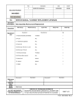
1- Fork Assembly
T3 Motion
1
2- 1-1/8 inch wrench
Any
1
3- Adjustable / Crescent wrench
Any
1
4- Diagonal cutter
Any
1
5- Adjustable Pliers
Any
1
6- ½ inch wrench
Any
1
7- Ratchet
Any
1
8- 7/16 socket
Any
1
9- Extension
Any
1
10- Swivel
Any
1
11- 5/32 inch Allen wrench
Any
1
Document #
Description
Description
Document #
Reference
Docs
Related
Files
RESP
ENGR
Mark Jones
ALL TEXT AND GRAPHICS
COMPUTER GENERATED, DO
NOT REVISE MANUALLY
T3MOTION, INC. PROPRIETARY INFORMATION
This document is the sole property of T3MOTION, Inc. The release of data
contained in this document and the reproduction of this document in whole
or in part, without the written permission of T3MOTION, Inc. is prohibited.
SHEET 1 of 15
Form 040-00064 Rev.1
SERVICE MANUAL
Item#
Part #
Description
Qty
1
024-00036
Front Fork Assembly
1
T3MOTION PROPRIETARY INFORMATION
Use or disclosure of data contained on this sheet is
subject to the restriction on the cover or title page of this
document.
Document No
Revision
040-00064
1
Sheet
2
SERVICE MANUAL
Serious electrical
shock can occur
if precautions are
not followed.
• ALWAYS TURN OFF POWER BREAKER IN GLOVE BOX AND REMOVE POWER
MODULES BEFORE PERFORMING ANY ELECTRICAL WORK.
Power breaker in glove box
Power modules
• ALSO SET THE PARKING BRAKE PRIOR TO ANY WORK.
Parking brake
T3MOTION PROPRIETARY INFORMATION
Use or disclosure of data contained on this sheet is
subject to the restriction on the cover or title page of this
document.
Document No
Revision
040-00064
1
Sheet
3
SERVICE MANUAL
WORK INSTRUCTIONS:
1.0
Recommended tools for replacing the fork assembly.
See equipment table above for the details.
1
10 8 9 7 6 3
2.0
2
5
4
11
Place the T3 unit on a raised surface sturdy enough to hold the weight of the vehicle,
(300 pounds). (Removing the batteries will lighten the vehicle by 40 pounds.)
The front wheel should be at least six inches from the ground, but ideally the unit
should be two to three feet off the ground for ease of handling the removal and
replacement of the fork assembly. A work table like the one shown below is very
helpful.
T3MOTION PROPRIETARY INFORMATION
Use or disclosure of data contained on this sheet is
subject to the restriction on the cover or title page of this
document.
Document No
Revision
040-00064
1
Sheet
4
SERVICE MANUAL
2.1
A stand like this can be placed under the front of the unit can to elevate the front wheel
if a work platform as described above is not available.
2.2
Be sure to set the parking brake. For maximum stability do not place the stand
too far back under the unit. Place it as shown below.
3.0
Take off the front fender by removing the Allen head fastener with the 5/32 Allen
wrench. Remove the left and right axle mounting ones first.
T3MOTION PROPRIETARY INFORMATION
Use or disclosure of data contained on this sheet is
subject to the restriction on the cover or title page of this
document.
Document No
Revision
040-00064
1
Sheet
5
SERVICE MANUAL
3.1
Next remove the left and right rear side fasteners with the same Allen wrench. If
your T3 unit only has these four fasteners attaching fender, remove the fender
now.
Note:
Most T3 units have four
fasteners attaching the front
fender, some have six.
3.2
If your T3 unit has two fasteners on the top of the front fender, remove
them now and the fender can be removed.
3.3
An exposed fork with fender removed:
T3MOTION PROPRIETARY INFORMATION
Use or disclosure of data contained on this sheet is
subject to the restriction on the cover or title page of this
document.
Document No
Revision
040-00064
1
Sheet
6
SERVICE MANUAL
4.0
Cut just the nylon wire tie holding the speedometer wire with the wire cutters to
release it from the guide. Unplug the connectors.
Wire Guide
Connectors
4.1
Remove the two main power cables from the motor with the ½ inch wrench.
Note:
Your motor may have a
black coating on the
terminal end.
Photo shows an un-coated
motor for clarity.
4.2
Remove the 7/16 bolt holding the wire conduit strap using a socket with an extension,
swivel and ratchet. The strap may have to be bent forward to access the head of the
bolt. This can be done by hand from the front or with a screwdriver from the side if
needed.
Wire Conduit Strap
T3MOTION PROPRIETARY INFORMATION
Use or disclosure of data contained on this sheet is
subject to the restriction on the cover or title page of this
document.
Document No
Revision
040-00064
1
Sheet
7
SERVICE MANUAL
5.0
Remove this cotter pin with pliers and or diagonal cutters and discard.
Urethane Bushing
Washer
Castle Nut
5.1
Loosen, but do not remove, 1-1/8 inch castle nut with wrench. Use crescent wrench on
fork for leverage as shown.
5.2
Support fork assembly while removing castle nut, washer and urethane bushing.
A little force applied
to the front of the tire
will wedge the
assembly onto the
shaft so you won’t
have to support the
full weight of the fork
while installing the
bushing, washer and
nut.
T3MOTION PROPRIETARY INFORMATION
Use or disclosure of data contained on this sheet is
subject to the restriction on the cover or title page of this
document.
Document No
Revision
040-00064
1
Sheet
8
SERVICE MANUAL
5.3
VERY IMPORTANT! Turn the fork as shown BEFORE removal. When facing the
front of the vehicle, the motor should be on your left and the tire pointing to your right.
Failure to do so will damage the bodywork of the T3 vehicle.
The fork assembly weighs 50 LBS. Use appropriate caution to avoid injury to self and
or vehicle.
Sometimes the fork will slip off the steering shaft easily; sometimes it must be worked
off with a side to side rocking motion. Once free of the shaft, lower the fork assembly to
the ground making sure the wiring does not snag on anything.
6.0
Installation of the new fork assembly is similar to the steps of removal in reverse.
New Fork Assembly
New Fork Assembly Parts
Urethane Bushing
Washer
Castle Nut
Cotter Pin
7/16 Bolt
Wire Conduit Strap
T3MOTION PROPRIETARY INFORMATION
Use or disclosure of data contained on this sheet is
subject to the restriction on the cover or title page of this
document.
Document No
Revision
040-00064
1
Sheet
9
SERVICE MANUAL
7.0
Feed the wire bundle through the 4 X 2-1/4 inch rectangular opening in the top of the
fork assembly.
Note angle of fork
assembly in relation to T3
unit.
Fork must be turned as
shown to avoid damage to
T3 unit’s bodywork.
Note parts are within
easy reach prior to
installing fork on
vehicle.
7.1
Slide the fork onto the steering shaft. Be sure the steering shaft is turned to the
(vehicles) left so the fork will align to the shaft easily.
7.2
Make sure the fork is fully seated to the shaft as shown here. Continue to support fork
while installing hardware even if it feels like it will stay on its own.
T3MOTION PROPRIETARY INFORMATION
Use or disclosure of data contained on this sheet is
subject to the restriction on the cover or title page of this
document.
Document No
Revision
040-00064
1
Sheet
10
SERVICE MANUAL
7.0
Install the fork mounting hardware. The urethane bushing goes on to the shaft first.
8.1
Slide the washer on the steering shaft.
8.2
Thread the castle nut on.
T3MOTION PROPRIETARY INFORMATION
Use or disclosure of data contained on this sheet is
subject to the restriction on the cover or title page of this
document.
Document No
Revision
040-00064
1
Sheet
11
SERVICE MANUAL
8.3
Tighten the castle nut with the 1-1/8 wrench using the crescent wrench again to
leverage against the fork.
8.4
Tighten the castle nut until it compresses the urethane bushing down to a maximum
height of 0.15 inches, (or 3.8mm). DO NOT UNDERTIGHTEN. If the slots in the nut
do not line up with the hole in the shaft once the bushing is compressed, continue to
tighten the nut until they do line up. It is better to over tighten the nut to line up the hole
for the cotter pin. Do not loosen the nut to line up the hole.
Urethane bushing
compressed to height of
0.15 inches.
Shaft hole and castle nut
slots lined up.
8.5
Install cotter pin and bend ends out flat as shown. Adjustable pliers are recommended.
T3MOTION PROPRIETARY INFORMATION
Use or disclosure of data contained on this sheet is
subject to the restriction on the cover or title page of this
document.
Document No
Revision
040-00064
1
Sheet
12
SERVICE MANUAL
9.0
9.1
Connect the wires to the motor. Use the ½ inch wrench.
IMPORTANT: Black goes to the Positive Terminal.
Plug the speedometer connectors together.
Wire Guide
Connectors
9.2
Mount the speedometer connectors to the wire guide with a nylon wire tie as shown.
Nylon Wire Tie
Connectors
Wire Guide
T3MOTION PROPRIETARY INFORMATION
Use or disclosure of data contained on this sheet is
subject to the restriction on the cover or title page of this
document.
Document No
Revision
040-00064
1
Sheet
13
SERVICE MANUAL
10.0
Slide the wire conduit strap over the conduit. Note position of fastening hole.
10.1
Start the 7/16 bolt into the threaded hole to fasten the strap to the fork. It might be
easier for you to start it by hand. This step may take some patience.
10.2
Using the 7/16 socket wrench with an extension and swivel, tighten the bolt/strap down.
T3MOTION PROPRIETARY INFORMATION
Use or disclosure of data contained on this sheet is
subject to the restriction on the cover or title page of this
document.
Document No
Revision
040-00064
1
Sheet
14
SERVICE MANUAL
11.0
Test for full range of motion. Slowly turn the fork assembly from lock to lock and make
sure the range of motion is smooth, with no binding. If any binding or lack of
smoothness is felt, visually check for any obstruction. DO NOT FORCE. The most
common cause of binding is due to the routing of the main power wires. You may have
to loosen the wire conduit strap and reposition the wires to alleviate any friction.
12.0
Reinstall front fender. Use the same fasteners you removed to take it off. Just reverse
the procedure. Do not fully tighten any of the fasteners until all of the fasteners are in
place. Do not over tighten the fasteners. Once installed, check the range of motion of
the steering again.
For addition information, contact T3 Motion at: (714)-619-3600.
T3MOTION PROPRIETARY INFORMATION
Use or disclosure of data contained on this sheet is
subject to the restriction on the cover or title page of this
document.
Document No
Revision
040-00064
1
Sheet
15