1
Rev
1
Description
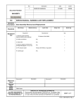
SERVICE MANUAL
Date
ECO#
2/14/2008
00239
Document Number:
040-00073
Form Instructions
Title
Operation
Description
Standards
Equipment
List
SERVICE MANUAL, THROTTLE ASSEMBLY REPLACEMENT
Sub Assembly
Man Occup.
Machine Occup.
Equipment
Cycle Time
Setup Time
Manufacturer
Batch Qty
Qty
1- Throttle Assembly
T3 Motion
1
2- Phillips screw driver
Any
1
3- 5/32 inch Allen wrench
Any
1
4- 7/16 inch socket
Any
1
5- Ratchet
Any
1
6- Wire cutters
Any
1
Document #
Description
Description
Document #
Reference
Docs
Related
Files
RESP
ENGR
Mark Jones
ALL TEXT AND GRAPHICS
COMPUTER GENERATED, DO
NOT REVISE MANUALLY
T3MOTION, INC. PROPRIETARY INFORMATION
This document is the sole property of T3MOTION, Inc. The release of data
contained in this document and the reproduction of this document in whole
or in part, without the written permission of T3MOTION, Inc. is prohibited.
SHEET 1 of 12
Form 040-00073 Rev.1
SERVICE MANUAL
Item#
Part #
Description
Qty
1
023-00014
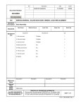
Throttle Assembly
1
T3MOTION PROPRIETARY INFORMATION
Use or disclosure of data contained on this sheet is
subject to the restriction on the cover or title page of this
document.
Document No
Revision
040-00073
1
Sheet
2
SERVICE MANUAL
Serious electrical
shock can occur
if precautions are
not followed.
• ALWAYS TURN OFF POWER BREAKER IN GLOVE BOX AND REMOVE POWER
MODULES BEFORE PERFORMING ANY ELECTRICAL WORK.
Power breaker in glove box
Power modules
• ALSO SET THE PARKING BRAKE PRIOR TO ANY WORK.
Parking brake
T3MOTION PROPRIETARY INFORMATION
Use or disclosure of data contained on this sheet is
subject to the restriction on the cover or title page of this
document.
Document No
Revision
040-00073
1
Sheet
3
SERVICE MANUAL
WORK INSTRUCTIONS:
1.0
Recommended tools for replacing the throttle assembly.
See equipment table above for the details.
Ratchet (5) with
Phillips screwdriver (2)
7/16 inch socket (4)
5/32 Allen wrench (3)
Wire cutters (6)
1.1
New throttle assembly.
2.0
Cut nylon tie wrap(s) securing wire to handlebar with wire cutters.
Note: Some T3 units
have one; and some
have two nylon wire
ties securing the wire
to the handlebar.
T3MOTION PROPRIETARY INFORMATION
Use or disclosure of data contained on this sheet is
subject to the restriction on the cover or title page of this
document.
Document No
Revision
040-00073
1
Sheet
4
SERVICE MANUAL
3.0
Remove these four screws with the 5/32 Allen wrench.
3.1
Remove these two screws with the 5/32 Allen wrench.
3.2
Carefully lift off the headset cover. Do not pull hard on the wires.
T3MOTION PROPRIETARY INFORMATION
Use or disclosure of data contained on this sheet is
subject to the restriction on the cover or title page of this
document.
Document No
Revision
040-00073
1
Sheet
5
SERVICE MANUAL
3.3
Locate the throttle connector on the circuit board.
3.4
Disconnect the plug for the throttle. Note the locking tab that must be released.
4.0
Remove the 7/16 inch bolt on the right hand side of the vehicle that secures the
headset to the handlebars.
Note routing of wires
to avoid pinching or
damaging them.
T3MOTION PROPRIETARY INFORMATION
Use or disclosure of data contained on this sheet is
subject to the restriction on the cover or title page of this
document.
Document No
Revision
040-00073
1
Sheet
6
SERVICE MANUAL
4.1
Loosen, but do not remove, the 7/16 inch bolt on the left hand side.
Note routing of wires
to avoid pinching or
damaging them.
4.2
Carefully pull apart the headset front and rear to allow the large handlebar
grommet to slide out. Do not force the plastic parts.
4.3
Slide the grommet out a bit so you can slide the connector under it. It takes two
hands.
T3MOTION PROPRIETARY INFORMATION
Use or disclosure of data contained on this sheet is
subject to the restriction on the cover or title page of this
document.
Document No
Revision
040-00073
1
Sheet
7
SERVICE MANUAL
4.4
Loosen the top Phillips head screw to allow the throttle assembly to slide off the
handlebar.
5.0
Slide the new throttle assembly all the way onto the handlebar.
5.1
Tighten both the top and bottom Phillips head screws to secure the throttle
assembly to the handlebar. Bottom screw being tightened in photo below.
Do not over tighten
the two screws that
secure the throttle to
the handlebar or
binding of the
throttle may occur.
T3MOTION PROPRIETARY INFORMATION
Use or disclosure of data contained on this sheet is
subject to the restriction on the cover or title page of this
document.
Check to make sure the
throttle returns smoothly
and rapidly when
released.
If binding occurs, back
off the screws a small
amount until it works
properly. Also make
sure the screws are
sufficiently tight to hold
the throttle on securely.
Document No
Revision
040-00073
1
Sheet
8
SERVICE MANUAL
5.2
Feed the connector and wire through the grommet much the same way as you
removed it earlier.
5.3
Slide the grommet back to its correct position so it lines up with the headset
parts.
5.4
Gently work the grommet and the headset parts back into alignment.
T3MOTION PROPRIETARY INFORMATION
Use or disclosure of data contained on this sheet is
subject to the restriction on the cover or title page of this
document.
Document No
Revision
040-00073
1
Sheet
9
SERVICE MANUAL
5.5
Hand thread to start the 7/16 bolt that holds the headset to the handlebars.
5.6
Tighten both 7/16 bolts with the socket wrench. Do not over tighten.
Note routing of wires
to avoid pinching or
damaging them.
5.7
Re-install the forward upper right Allen head screw to fasten the headset around
the grommet. Do not over tighten or force. Tighten just enough to close the gap
here. If the gap won’t close, inspect the area to find what is interfering.
Also see step 7.1 for reinstalling the headset
screw on the back lower
right at this time if you are
having difficulty closing the
gap.
T3MOTION PROPRIETARY INFORMATION
Use or disclosure of data contained on this sheet is
subject to the restriction on the cover or title page of this
document.
Document No
Revision
040-00073
1
Sheet
10
SERVICE MANUAL
6.0
Plug the throttle connector to the circuit board as shown. Note position of locking
tab.
7.0
Re-install headset top. Be sure to arrange wires so there is no binding or
pinching.
7.1
Re-install headset top mounting screws. Thread all four of them in part way
before tightening any of them. Do not over tighten them.
There are the two on the back, shown here.
Also install and tighten the
headset screw on the back
lower right at this time if
you have not already done
so.
T3MOTION PROPRIETARY INFORMATION
Use or disclosure of data contained on this sheet is
subject to the restriction on the cover or title page of this
document.
Document No
Revision
040-00073
1
Sheet
11
SERVICE MANUAL
7.2
And these are the two on the front under the head light.
8.0
Turn power on and test to make sure everything works properly.
9.0
Secure wire to handlebar with a nylon tie wrap and cut excess from tie with wire
cutters.
For addition information, contact T3 Motion at: (714)-619-3600.
T3MOTION PROPRIETARY INFORMATION
Use or disclosure of data contained on this sheet is
subject to the restriction on the cover or title page of this
document.
Document No
Revision
040-00073
1
Sheet
12