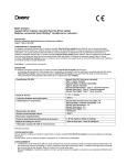
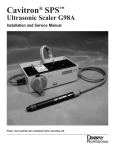
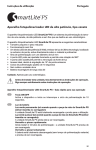
1
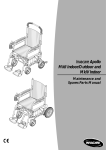
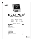
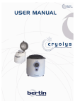
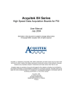
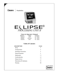
Cavitron® JET Plus™ Troubleshooting and Analysis, continued
This troubleshooting section is meant for use by qualified Cavitron® Service Technicians.
SYMPTOMS
CAUSES
CORRECTIVE MEASURES
Intermittent scaling power or no 9. Foot Control malfunction.
scaling power.
(Continued)
Handpiece heats up.
9. Connect the auxiliary Foot Control cable between
the Foot Control and the unit. If the unit will not
operate with the auxiliary cable connected, replace
the Foot Control. Follow the Cavitron® JET Plus™
Directions for Use and Service Manual instructions
for Foot Control synchronizing.
1. Insufficient water to cool
handpiece.
1. Increase the setting on the handpiece lavage
control until handpiece runs cool.
2. Air trapped in the handpiece.
2. When the inserts are changed, hold the handpiece
in an upright position until the trapped air is
removed and the water flows properly.
3. Insert water passageway clogged. 3. Replace the Cavitron® insert and check operation.
4. Handpiece cable not supported
during procedure.
4. Loop handpiece cable around arm or support with
finger to prevent water restriction.
5. Worn insert being used.
5. Replace with a new Cavitron® insert. Worn inserts
require higher power settings producing more
heat.
Insert vibrates but no water or
1. Low incoming dental office water
insufficient water flows from the
pressure.
handpiece.
2. Water filter clogged.
1. Measure water pressure at dental office.
Adjust incoming source water pressure to
specification. Water pressure should be 20-40
psi.
2. Replace the water filter when discolored or
restriction occurs.
3. Handpiece cable water tubing and 3. Remove restriction if possible or replace
wires twisted.
handpiece cable assembly.
4. Damaged handpiece cable Flow
Control.
4. Replace handpiece cable assembly.
5. Obstruction or mineral deposits in
the water system in the unit.
5. a. Remove the insert and turn the water valve
full open. Observe the water flow. If the flow
is good then the obstruction is in the insert.
b. If the obstruction is not in the insert, then
remove the handpiece water line at solenoid
and check the water flow. If flow is good, then
the obstruction is in handpiece supply line.
26
Cavitron® JET Plus™ Troubleshooting and Analysis, continued
This troubleshooting section is meant for use by qualified Cavitron® Service Technicians.
SYMPTOMS
CAUSES
CORRECTIVE MEASURES
No water flow from handpiece
with no insert installed.
1. High dental office water pressure. 1. Install a water pressure regulator on the main
water supply line and reduce the pressure to
20-40 psi.
Water spray from insert is not
properly covering the operating
area of the activated tip.
1. Improper water flow adjustment.
1. Refer to Cavitron® JET Plus™ Directions for Use
for instructions on water flow adjustment.
2. P-style insert water tube
incorrectly aimed.
2. Use small smooth pliers, reposition the water tube
and direct the spray at the back of the insert tip.
3. Insert or Air Polishing nozzle
insert is partially clogged.
3. Replace the insert or Air Polishing nozzle insert.
Water drips from the handpiece
when not operating.
1. Water solenoid valve leaking due
to trapped debris.
1. Try plugging the water supply hose into an air
source to blow out the dirt. If the leak persists,
replace the regulator/solenoid assembly. Be sure
the external hose filter is installed.
Water leak from the handpiece
while in operation.
1. O-ring worn on insert.
1. Replace the o-ring with genuine Cavitron® o-rings.
O-rings are available in packs of 12:
Green O-Rings P/N 62605
Black O-Rings P/N 62351
2. Water leak in plastic water line
at handpiece or inside the
JET-Mate™ Handpiece.
2. a. Unplug the JET-Mate™ handpiece from the
cable and replace the small o-ring on the
connector. Part No. 79357 (12-Pack)
b. Replace the JET-Mate™ handpiece and/or
cable assembly.
Water flow not controllable
by turning the handpiece flow
control knob.
1. Malfunction of water regulator /
solenoid assembly.
1. Replace the water regulator / solenoid valve
assembly. Adjust the water regulator to
specifications.
Intermittent activation or no
activation when stepping on
the foot control.
1. Foot Control batteries are weak.
1. a. Check Foot Control battery condition.
Replace batteries as required.
b. Connect the auxiliary Foot Control cable
between the Foot Control and unit. The unit
can be operated with the cable until the
battery is replaced.
27
Cavitron® JET Plus™ Troubleshooting and Analysis, continued
This troubleshooting section is meant for use by qualified Cavitron® Service Technicians.
SYMPTOMS
Intermittent activation or no
activation when stepping on the
foot control.
CAUSES
CORRECTIVE MEASURES
2. Foot Control is not synchronized
to the base unit.
(Continued)
Boost Power mode does
not activate. Information
Center “Boost” LED does not
illuminate.
Scaling inserts cannot be
installed in the handpiece
properly.
Purge mode does not activate
and the Purge light blinks five
times when depressed.
2. a. Follow the Cavitron® JET Plus™ Directions for
Use and Service Manual instructions for Foot
Control synchronization.
b. Connect the Auxiliary Foot Control cable
between the Foot Control and the unit. The
unit can be operated with the cable until the
Foot Control is re-synchronized.
3. Malfunction in the Foot Control.
3. Replace the Foot Control. Follow the Cavitron®
JET Plus™ Directions for Use and Service Manual
instructions for Foot Control synchronization.
1. Foot Control not fully depressed.
1. Depress the Foot Control fully. The “Boost” LED
should illuminate.
2. Air Polishing nozzle insert is
installed in the handpiece.
2. Scaling insert must be installed in the handpiece
for the Boost mode to activate.
3. The Foot Control is defective.
3. Replace the Foot Control. Follow the Cavitron®
JET Plus™ Directions for Use and Service Manual
instructions for Foot Control synchronization.
1. O-ring on the insert is dry.
1. Lubricate the o-ring with water. If the o-ring is
worn, replace it.
2. Incorrect or damaged O-ring
installed on the insert
2. Replace the insert O-ring with Cavitron® O-rings.
O-rings are available in packs of 12:
Green O-Rings P/N 62605
Black O-Rings P/N 62351
1. Scaling insert or Air Polishing
1. Purge mode will only operate with the handpiece
insert is installed in the handpiece.
empty. Remove the insert and re-press the Purge
button.
2. The JET-Mate™ is not installed
2. Install a JET-Mate™ on the handpiece cable
on the handpiece cable assembly.
assembly. Press the Purge button.
3. Open coil or connection on the
JET-Mate™ assembly.
3. Replace the JET-Mate™ with a known good
handpiece. Press the Purge button.
4. Open connection on the
handpiece cable assembly.
4. Replace the handpiece cable assembly.
5. Problem on the PC board(s).
5. Return the Cavitron® JET Plus™ unit to
DENTSPLY® for factory certified service.
28
Cavitron® JET Plus™ Troubleshooting and Analysis, continued
This troubleshooting section is meant for use by qualified Cavitron® Service Technicians.
SYMPTOMS
Info Center Service light is
blinking fast (3 blinks per
second).
Info Center Service light is
blinking slowly (1 blink per
second).
Info Center Service light
stays on.
CAUSES
CORRECTIVE MEASURES
1. The JET-Mate™ is not installed
on the end of the handpiece
cable.
1. Install the JET-Mate™ on the handpiece cable and
activate the Foot Control.
2. Open coil or connection on the
JET-Mate™ handpiece.
2. Replace the JET-Mate™ with a known good one.
Activate the Foot Control.
3. Open connection on the
handpiece cable assembly.
3. Replace handpiece cable assembly.
4. Problem on the PC board(s).
4. Return the Cavitron® JET Plus™ unit to
DENTSPLY® for factory certified service.
1. Insert is damaged or out of
specification.
1. Install a new Cavitron® 30K insert in the
handpiece and activate the Foot Control.
2. Faulty JET-Mate™ handpiece.
2. Install a new JET-Mate™ handpiece on the
handpiece cable and activate the Foot Control.
3. Base unit is out of calibration.
3. Return the Cavitron® JET Plus™ unit to
DENTSPLY® for factory certified service.
4. Problem on the PC board(s).
4. Return the Cavitron® JET Plus™ unit to
DENTSPLY® for factory certified service.
1. Unit is installed in a confined area 1. Provide adequate air circulation around unit.
(such as a cabinet), or is too
Service light will turn off when the unit returns to
close to a heat source to insure
normal operating temperature.
proper air circulation around unit.
2. Problem on the PC board(s).
29
2. Return the Cavitron® JET Plus™ unit to
DENTSPLY® for factory certified service.
Cavitron® JET Plus™ Troubleshooting and Analysis, continued
This troubleshooting section is meant for use by qualified Cavitron® Service Technicians.
SYMPTOMS
Air Polishing inserts are difficult
to install in the handpiece or
leak.
CAUSES
CORRECTIVE MEASURES
1. The Air Polishing nozzle insert
o-ring is damaged or deformed.
1. Replace the green o-ring on the nozzle heater rod.
O-rings are available in packs of 12:
Green O-Rings P/N 62605
2. O-ring was not lubricated with
water before inserting.
2. Fill the handpiece and wet the Air Polishing Nozzle
insert o-ring before inserting.
3. The handpiece soft nozzle grip
connector is deformed.
3. Remove, clean the ridged handpiece with a soft
brush and replace the Handpiece soft nozzle grip
connector. P/N 81717.
Cleaning air flow from the nozzle 1. Powder flow pointer on the bowl
is normal but there is little or
cap is in the wrong position.
no powder flow.
2. Clogged center tube in the
powder bowl.
Cleaning air flow from the Air
Polishing nozzle is insufficientno powder delivery.
1. Adjust the pointer to the “H“ or 12 o‘clock
position.
2. Dump out the powder and clean out the bowl
assembly.
3. Caked powder in the bowl
assembly.
3. Remove the tube attached to the bowl bottom
L-Nozzle and check airflow.
4. Powder bowl L-Nozzle clogged.
4. Use the cleaning tool and clean out the L-Nozzle
from both ends.
5. Handpiece and/or Air Polishing
insert are partially clogged.
5. Use the cleaning wires and clean out the
handpiece and Air Polishing insert.
1. Improper daily Cavitron® JET
Plus™ unit maintenance by the
operator.
1. Refer the operator to the Cavitron® JET
Plus™ Directions for Use manual or Air Polishing
maintenance information.
2. Insufficient air pressure is being
supplied to the unit.
2. Check the dental office air supply for 65 to 100
psi air pressure.
3. Use of non-DENTSPLY ®powder.
3. Replace the powder with fresh DENTSPLY®
Prophy-JET® or JET-Fresh™ Powder.
4. Use of old or moisture
contaminated powder.
4. Replace the powder with fresh DENTSPLY®
Prophy-JET® or JET-Fresh™ Powder.
5. Powder bowl cap leaking air.
5. Unscrew the cap and remove the cap o-ring. Use
water to wash both, dry thoroughly and reinstall.
Replace the cap assembly or o-ring as needed.
Cap assembly P/N 81728, O-Ring P/N
628052001.
6. Clogged powder bowl fitting or
bowl bottom nozzle.
6. Empty the powder bowl, unscrew the bowl bottom
nozzle at the bottom of the bowl and clean out any
caked powder.
30
Cavitron® JET Plus™ Troubleshooting and Analysis, continued
This troubleshooting section is meant for use by qualified Cavitron® Service Technicians.
SYMPTOMS
CAUSES
Cleaning air flow from the Air
Polishing nozzle is insufficientno powder delivery.
7. Oil or moisture in the air supply
to the Cavitron® JET Plus™.
Check for wet or discolored
external and internal filter
elements.
(Continued)
CORRECTIVE MEASURES
7.
a. Have the dental office air compressor
serviced.
b. An air dryer and filter should be installed to
remove moisture and contaminants.
c. Return the Cavitron® JET Plus™ unit to
DENTSPLY® for factory certified service.
8. Duckbill filters were removed or
installed in reverse.
8.
Return the Cavitron® JET Plus™ unit to
DENTSPLY® for factory certified service.
9. Main air regulator in the
Cavitron® JET Plus™ is set too
low.
9.
Return the Cavitron® JET Plus™ unit to
DENTSPLY® for factory certified service.
10. Clogged air tubing in the
Cavitron® JET Plus™ or the
handpiece.
10. Return the Cavitron® JET Plus™ unit to
DENTSPLY® for factory certified service.
Cavitron® JET Plus™ unit has no 1. The Air Polishing insert is
bleed air.
clogged.
1. Remove the Air Polishing insert and check the
handpiece for bleed air. Use the cleaning tool to
clear the Air Polishing insert if it is clogged.
2. The Cavitron® JET Plus™ air
supply is not hooked up.
2. Check the unit air hose and air compressor.
3. The manifold bleed air needle
valve is set too low.
3. Connect a calibrated bleed air gauge and adjust
the needle valve to specifications.
4. The bleed air duckbill filter is
clogged or installed incorrectly.
4. Remove the filter assembly and inspect. Replace if
clogged or damaged. P/N 60367.
5. The Y-Fitting is clogged.
5. Remove the tubes and clear the obstruction with a
cleaning wire.
6. The JET-Mate™ handpiece air/
powder tube is clogged.
6. Unplug and clean out the handpiece with the long
cleaning wire.
7. The handpiece cable tubing is
clogged.
7. Unplug and clean out the handpiece assembly by
applying compressed air to the HP tubing.
8. The air manifold is defective or
clogged.
8. Remove the bleed air tubing at the air manifold
and check for air flow. Repair or replace the air
manifold as needed.
31
Cavitron® JET Plus™ Troubleshooting and Analysis, continued
This troubleshooting section is meant for use by qualified Cavitron® Service Technicians.
SYMPTOMS
Abnormally high bleed air with
powder leaking.
(Foot Control not activated)
CAUSES
CORRECTIVE MEASURES
1. The pinch valve assembly is
leaking air and not fully sealing
the red pinch tube.
1. Return the Cavitron® JET Plus™ to DENTSPLY®
for factory certified service.
2. Non-Cavitron® red pinch tubing
installed in the unit.
2. Only Cavitron® red pinch tubing should be installed
in the unit. Replace tubing. P/N 61631.
Nozzle and/or handpiece tubing 1. Oil or moisture is in the air supply
is clogged.
to the unit.
1. a. Have the office air compressor serviced.
b. Return the Cavitron® JET Plus™ to
DENTSPLY® for factory certified service.
Powder bowl cap cannot be
unscrewed.
2. Bleed air is set too low.
2. Connect a calibrated Bleed Air gauge and adjust
the needle valve to specifications.
3. Y-Connector in the unit is clogged
with powder.
3. Clean out the Y-Connector with a cleaning wire.
1. Cavitron® JET Plus™ unit is still
powered up.
1. Switch off the power and allow the bowl chamber
to depressurize.
2. Powder bowl chamber is not fully
depressurized.
2. Allow sufficient time (about 10 sec.) for the
powder bowl to depressurize.
3. Powder bowl internal chamber
filter is clogged.
3. Remove the tubing on the bowl bottom L-Nozzle.
Allow the bowl to depressurize then disassemble
the bowl assembly and clean the filter.
4. Main air solenoid not sealing when 4. a. Replace the Air Manifold assembly.
the unit is powered down.
b. Return the Cavitron® JET Plus™ to
DENTSPLY® for factory certified service.
Water spray pattern from
the Air Polishing insert is not
uniform.
1. The concentric tubes of the Air
Polishing Nozzle insert are
clogged with dirt or are off
center.
1. a. Insert a cleaning wire in the front of the nozzle,
gently rotate the center tube around to
dislodge any dirt with the water spray. Unconcentric tubes can be corrected by gently
bending the outer tube.
b. Replace the Air Polishing insert with a new
one. P/N 63740.
32
B. Fuse Testing Procedure:
SECTION 17:
Disassembly and
Service Procedures
White Wire
CAUTION: THIS UNIT CONTAINS COMPONENTS
WHICH ARE SUBJECT TO ELECTROSTATIC
DISCHARGE (ESD) DAMAGE. THE WORKSTATION
SURFACE AND REPAIR TECHNICIAN MUST BE
PROPERLY GROUNDED PRIOR TO REMOVAL OF
THE COVER.
1. Follow this procedure to test the condition of fuses, F3
and F4, without removing the protective cover on the
power entry module.
2. Unplug the power cord from the rear Power Entry
module.
3. Refer to the “Top Cover Removal” in Section A.
4. Ensure that the Power Switch is in the ON position.
5. Use a DVM in the Ohm setting to measure the
continuity.
6. Place one probe on the LEFT terminal of the Power
Entry module.
7. Place the other probe on the WHITE wire connector at
the front of the Power Supply assembly.
8. If the DVM reads continuity, the F4 fuse is good.
9. Repeat Steps 6 thru 8 to test fuse F3 using the right
terminal of the power entry module and BLACK wire.
INDEX:
A.
B.
C.
D.
E.
F.
G.
H.
I.
J.
K.
L.
M.
Black Wire
Top Cover Removal
Fuse Testing Procedure
Fuse Replacement
Handpiece Cable Assembly Replacement
Water Solenoid/Regulator Replacement
Power Supply Assembly Replacement
Power Drive PC Board Replacement
Information Center PC Board Replacement
Main Controller PC Board Replacement
Air Manifold Assembly Replacement
Pinch Valve Replacement
Pinch Tube Replacement
Air Manifold Connections
C. Fuse Replacement:
1. Refer to the “Top Cover Removal” in Section A. Ensure
that the power cord has been unplugged from the rear
power entry module.
2. The Power Drive PC board is mounted vertically in the
left-rear of the base cabinet. Unplug the Top Cover
ribbon cable at J5 on the Power Drive PC board and
place the Top Cover to the side. Unplug the power
supply harness from J1 on the Power Drive PC board.
3. Remove the plastic barrier from the center of the unit.
Pull the barrier away from the heatsink to release the
two-sided tape and lift it out of the unit.
4. Use a screwdriver and remove the two #8 x 1/2” Hi-Lo
screws at the base of the heatsink bracket. Work
carefully to prevent damage to the Power Drive PC
board components.
5. Use a screwdriver and remove the two #6 x 1/2” Hi Lo
screws located at the back corners of the Power
Supply Assembly.
6. Tilt the Power Supply assembly up to allow the Power
Drive PC board to be lifted out of position. Use care
not to damage connector J7. It is mounted on the
back of the Power Drive PC board and protrudes
through the rear cabinet housing. This will allow
access to the power entry cover.
7. Use a screwdriver and remove the #6-32 x 3/8” screw
on the Power Entry cover.
A. Top Cover Removal:
1. Power off the Cavitron® JET Plus™ using the
front rocker switch.
2. Unplug the Power Cord from the rear receptacle.
3. If the auxiliary Foot Control cable was being used,
disconnect it from the rear of the unit.
4. Disconnect the blue water hose by unplugging the
quick disconnect at the supply. Depress the tip of the
quick disconnect in a suitable container to relieve the
water pressure.
5. Turn the Cavitron® JET Plus™ over. Place it on
a clean non-abrasive surface to prevent damage to the
cabinet cover.
6. Use a screwdriver and remove the six #6 x 1/2” Hi-Lo
recessed screws located along the front and back of
the unit.
7. Support the Top Cover against the cabinet base and
return the scaler to the upright position. Collect and
save the six screws for re-assembly.
8. Lift the Top Cover from the front and support it
adjacent to the Bottom Housing to prevent damage to
the ribbon cable.
33
board. Route the Handpiece cable down against the
chassis.
8. Lift the protective cover from the Power Entry module.
The fuses are mounted vertically under the cover.
Use a small flat blade screwdriver and lift the fuses
from the clips.
9. Replace the fuses with the specified current rating and
voltage.
10. Replace the Power Entry module cover. Insert and
tighten the cover screw. Lower and align the heatsink
bracket and tighten the two screws with a screwdriver.
Check for proper alignment of the auxiliary Foot
Control cable connector on the back panel and that
no wires are trapped.
11. Install and tighten the two screws at the rear corners
of the Power Supply assembly.
12. Align the plastic barrier with the Bottom Housing and
fully seat. Replace the two-sided tape, if necessary, to
secure the barrier to the heatsink.
13. Reconnect the ribbon cable from the Top Cover.
Support the Top Cover on the rear of the base cabinet.
14. Align the Top Cover on the Bottom Housing and
securely fasten the six #6 x 1/2” Hi-Lo screws using a
screwdriver.
15. Plug in the power cord into the power entry module.
16. Power up the unit using the power rocker switch and
test unit operation.
17. Calibrate and final test the Cavitron® JET Plus™
using the DENTSLY® Professional - Product Service
Standard Operating Procedure, PS-154.
HP
Water Regulator/Solenoid
J3
J2
12. Align the plastic barrier with the Bottom Housing and
fully seat. Replace the two-sided tape, if necessary, to
secure the barrier to the heatsink.
13. Route the handpiece water tubing by first creating a
counter-clockwise loop above the strain relief. Then
route the tubing along the chassis between the Pinch
Valve and Air Manifold. Connect it to the Water
Regulator/Solenoid.
14. Connect the red Handpiece air/powder tubing to the
Y-connector. Be sure the tubing is fully seated and not
kinked.
15. Reconnect the ribbon cable at J5 on the Power PC
Drive board. Support the Top cover to prevent
damage to cable.
16. Power up the unit, install an insert in the handpiece,
and check the scaling power and water flow. Inspect
the clear handpiece water tubing for any water leaks.
17. Calibrate and final test the Cavitron® JET Plus™
using DENTSPLY® Professional - Product Service
Standard Operating Procedure, PS-154.
D. Handpiece Cable
Assembly Replacement:
1. If possible, plug the water supply hose into a
compressed air source (40 psi max.) and operate the
unit to discharge all water from the unit and handpiece.
2. Follow the steps above in Section A for “Top Cover
Removal”.
3. Unplug the Top Cover ribbon cable at J5 on the Power
Drive PC board and place the Top Cover to the side.
4. Remove the plastic barrier from the unit. Pull the
barrier away from the heatsink to release the twosided tape and lift the barrier out of the unit.
5. Unplug the 3-wire Handpiece cable from J3 on the
Power Drive PC board.
6. Carefully slide the Handpiece water tubing from the
Regulator/Water Solenoid assembly.
7. Unplug the red Handpiece air/powder tubing from the
metal Y-connector.
8. Apply slight pressure upward on the Handpiece cable
strain relief. At the same time, separate the plastic
clips and fully disengage the handpiece strain relief
and cable from the cabinet base.
9. Pass the wiring and water tubing through the Bottom
Housing opening.
10. Insert the new handpiece wire connector and water
tubing through the bottom of the cabinet base. Align
and snap the strain relief into the tabs.
11. Plug the 3-wire connector onto J3 of the Power PC
E. Water Regulator/Solenoid
Assembly Replacement:
1. Follow the steps above in Section A for “Top Cover
Removal”.
2. Unplug the Top Cover ribbon cable at J5 on the Power
Drive PC board and place the Top Cover to the side.
3. Unplug the blue water hose assembly at the source
and relieve the water pressure by pressing the quick
disconnect tip in a suitable container. Disconnect the
blue water hose at the rear of the unit by fully
depressing the gray connector ring and gently pulling
out the hose.
4. Unplug the black air hose assembly at the source and
relieve the air pressure by depressing the quick
disconnect tip. Disconnect the black air hose at the
rear of the unit by fully depressing the connector ring
and gently pulling out the hose.
5. Remove the plastic barrier from the unit. Pull the
barrier away from the heatsink to release the two-sided
tape and lift the barrier out of the unit.
6. Unplug the Water Regulator/Solenoid assembly at J2
on the Power Drive PC board.
34
7. Use a screwdriver and remove the two #6 x 1/2” Hi-Lo
screws at the front corners of the Air/Water chassis
assembly. Use a screwdriver and remove the #6-32 x
3/8” screw on the Power Entry cover. Carefully lift up
the Air/Water chassis assembly.
8. Use a screwdriver and remove the two #6 x 3/8”
screws directly under the Water Regulator/Solenoid
assembly. Use a flat blade screwdriver and remove
the two elbow barbed fittings from the rear of the
Water Regulator/Solenoid assembly. The tubing
does NOT have to be removed from the barbed
fittings. Position the replacement Water Regulator/
Solenoid assembly over the same mounting bracket
holes and fasten with the removed screws.
9. Reinstall the elbow barbed fittings onto the replacement Water Regulator/Solenoid assembly.
13. Plug the Water Regulator/Solenoid Wire connector into
J2 on the Power Drive PC board.
HP
Water Regulator/Solenoid
J3
J2
14. Insert the blue water hose into the lower right-hand
hose connector in the back panel. Be sure it is fully
seated.
15. Insert the black Air hose into the lower left-hand
(corner) hose connector in the back panel. Be sure it is
fully seated.
16. Align the plastic barrier with the Bottom Housing
and fully seat. Replace the two-sided tape, if
necessary, to secure the barrier to the heatsink.
17. Reconnect the ribbon cable at J5 on the Power Drive
PC board. Support the Top Cover to prevent damage
to the cable.
18. Calibrate and final test the Cavitron® JET Plus™
using DENTSPLY Professional - Product Service
Standard Operating Procedure, PS-154.
NOTE: The small clear handpiece tube goes on the
TOP port (marked A). The larger blue water supply
tube goes on the BOTTOM port (marked P). Refer
to image below.
F. Power Supply Assembly Replacement:
1. Follow the steps in Section A for “Top Cover Removal”.
2. Unplug the Top Cover ribbon cable at J5 on the Power
Drive PC board and place the Top Cover to the side.
3. Remove the plastic barrier from the unit. Pull the
barrier away from the heatsink to release the two-sided
tape and lift the barrier out of the unit.
4. Locate the BLK-WHT wire harness that is connected
to the power switch and unplug it from the Power
Supply assembly.
5. Unplug the Ground Lug at the front-right corner of the
Power Supply assembly.
6. Unplug the BLK-RED wire connector at J1 on the Power
Drive PC board.
7. Use a screwdriver and remove the two #6 x 1/2” Hi-Lo
screws at the back corners of the Power Supply
assembly.
8. Lift and slide the Power Supply assembly toward the
rear of the unit to disengage it from the front mounted
tabs and remove.
9. Inspect the cabinet base for the presence of the two
D-section support cushions. Replace if damaged or
missing.
10. Position the replacement Power Supply assembly with
the RED-BLK wire connector at the rear.
11. Slide the Power Supply assembly under the front
molded tabs and fasten with the two #6 x 1/2” Hi-Lo
using a screwdriver.
10. Lower the Air/Water chassis assembly and slide it back
under the molded tab located adjacent to the water
inlet hole.
11. Ensure that the Regulator/Solenoid wires, Handpiece
cable assembly and Handpiece water tubing and
blue supply tube are not trapped under the Air/Water
chassis assembly. Use a screwdriver and fasten the
Air/Water chassis assembly to the cabinet base. The
Ground wire terminal must be reinstalled over the left
mounting bracket tab. Place the lock-washer between
the screw head and the Ground wire terminal. Use a
screwdriver and fasten the Power Entry cover to
the Air/Water chassis assembly.
12. The clear Handpiece water tubing must be looped
above the Handpiece cable strain relief then routed
between the Pinch Valve and Air Manifold assembly.
35
12. Reconnect the RED-BLK wire connector to J1 on the
Power Drive PC board.
13. Reconnect the BLK-WHT mains voltage wires from the
rocker switch to the Power Supply connector. Install
the Ground wire to the tab at the front right corner on
the Power Supply. Ensure all connectors are fully
seated.
14. Align the plastic barrier with the Bottom Housing
and fully seat. Replace the two-sided tape, if
necessary, to secure the barrier to the heatsink.
15. Reconnect the ribbon cable at J5 on the Power PC
Drive board. Support the Top cover to prevent
damage to cable.
16. Calibrate and final test the Cavitron® JET Plus™
using DENTSPLY® Professional - Product Service
Standard Operating Procedure, PS-154.
14.
15.
16.
17.
Solenoid was designed with a longer cable to reach
the J6 position.)
Reconnect the BLK-RED wire connector from the Power
Supply Assembly to J1.
Align the plastic barrier with the Bottom Housing
and fully seat. Replace the two-sided tape, if
necessary, to secure the barrier to the heatsink.
Reconnect the ribbon cable at J5 on the Power Drive
PC board. Support the Top Cover to prevent damage
to the cable.
Calibrate and final test the Cavitron® JET Plus™
using DENTSPLY Professional - Product Service
Standard Operating Procedure, PS-154.
H. Information Center
PC Board Replacement:
G. Power Drive PC Board Replacement:
1. Follow the steps above in Section A for “Top Cover
Removal”.
2. Unplug the ribbon cable at the Power Drive PC board
at J5 to allow better access to the Top cover
assembly.
3. Unplug the ribbon cable that is plugged into J1 on the
Information Center PC board. Use a screwdriver and
remove the four 4-24 x 1/2” Hi-Lo screws.
4. Replace the Information Center PC board. Transfer the
protective cover to the replacement PC board. Align
the board against the molded overlay panel and fasten
with the four 4-24 x 1/2” Hi-Lo screws. Be sure the
leveling washers are correctly positioned. Do not overtighten the screws. Reconnect the ribbon cable to J1
on the Info Center PC board.
5. Reconnect the ribbon cable at J5 on the Power Drive
PC board. Support the Top Cover to prevent damage
to the cable.
6. Calibrate and final test the Cavitron® JET Plus™
using DENTSPLY Professional - Product Service
Standard Operating Procedure, PS-154.
1. Follow the steps above in Section A for “Top Cover
Removal”.
2. Unplug the Top Cover ribbon cable at J5 on the Power
Drive PC board and place the Top Cover to the side.
3. Remove the plastic barrier from the unit. Pull the
barrier away from the heatsink to release the two-sided
tape and lift it out of the unit.
4. Depress the clip and unplug the BLK-RED wire
connector from the Power Drive PC board at J1.
5. Unplug the Handpiece Cable assembly at J3 on the
Power Drive PC board.
6. Unplug the Water Regulator/Solenoid assembly cable
at J2 on the Power Drive PC board.
7. Unplug the main Air Inlet Solenoid assembly cable at
J6 on the Power Drive PC board.
8. Unplug the Pinch Solenoid assembly cable at J4 on the
Power Drive PC board.
9. Use a screwdriver and remove the two #6 x 1/2” Hi Lo
screws at the back corners of the Power Supply
assembly.
10. Use a screwdriver and remove the two #8-18 x 1/2”
Hi-Lo heatsink bracket screws at the bottom. Tilt the
Power Supply assembly up to allow the Power Drive
PC board to be lifted out of position. Remove the
Power Drive PC board / heatsink bracket assembly
from the unit. The Power Drive PC board, pink Sil-pad
and heatsink bracket are manufactured, tested and
available only as a complete assembly.
11. Lower the replacement Power Drive PC board
assembly back into the Bottom Housing. Use caution
to prevent damage to connector J7 on the back of the
Power Drive PC board.
12. Securely fasten the Power Drive PC board assembly
with the two #8 x 1/2” Hi-Lo screws using a screwdriver. Install and tighten the two screws in the
Power Supply assembly.
13. Reconnect the Pinch Solenoid cable to J6, the
Handpiece cable to J3, the Water Regulator Solenoid
at J2, and the main Air Solenoid to J4. (The Pinch
Info Center PCB
4” Folded Ribbon Cable
Main Controller Board
Molded Overlay
I. Main Controller PC Board Replacement:
1. Follow the steps above in Section A for “Top Cover
Removal”.
2. Unplug the ribbon cable at the rear at J5 on the Main
Controller PC board.
3. Unplug the ribbon cable from the Information Center
PC board at J1 on the Main Controller PC board.
36
4. Unplug the Power Potentiometer cable harness at J4
on the Main Controller PC board.
5. Use a screwdriver and remove the four 4-24 x 1/2”
Hi-Lo screws. Lift off the leveling washers.
6. Lift off the Main Controller PC board and install the
replacement, with grommets over the molded studs.
Be sure the board is level. Use the four 4-24 x 1/2”
Hi-Lo screws and leveling washers to secure the PC
board. The leveling washers must be rotated to have
the thicker profile facing the rear of the top cover.
7. Reinstall the Power Potentiometer cable harness at J4.
8. Install the connector on the ribbon cable from the
Information Center PC board at J1.
9. Position the Top Cover assembly behind the Bottom
Housing and install the ribbon cable at J5 on the Power
Drive PC board.
10. Calibrate and final test the Cavitron® JET Plus™
using DENTSPLY® Professional - Product Service
Standard Operating Procedure, PS-154.
14.
15.
16.
J. Air Manifold Assembly Replacement:
17.
1. Follow the steps above in Section A for “Top Cover
Removal”.
2. Unplug the Top Cover ribbon cable at J5 on the Power
Drive PC board and place the Top Cover to the side.
3. Unplug the blue water hose assembly at the source
and relieve the water pressure by depressing the quick
disconnect tip in a suitable container. Disconnect the
blue water hose at the rear of the unit by fully
depressing the gray connector ring and gently pulling
out the hose.
4. Unplug the black air hose assembly at the source and
relieve the air pressure by depressing the quick
disconnect tip. Disconnect the black air hose at the
rear of the unit by fully depressing the connector ring
and gently pulling out the hose.
5. Remove the plastic barrier from the unit. Pull the
plastic barrier away from the heatsink to release the
two-sided tape and lift the barrier out of the unit.
6. Unplug the main Air Inlet Solenoid cable at J4 on the
Power Drive PC board.
7. Unplug the Pinch Solenoid cable at J6 on the Power
Drive PC board.
8. Disconnect the clear Pinch Valve tubing from the top
Air Manifold barbed fitting.
9. Disconnect the (upper) Duckbill filter with gray tubing
from the center Air Manifold barbed fitting.
10. Disconnect the (lower) Duckbill filter with the clear
tubing from the bottom Air Manifold barbed fitting.
11. Disconnect the yellow tubing from the bottom Air
Manifold fitting location with the Restrictor barbed
fitting.
12. Use a screwdriver and remove the two #6 x 1/2” Hi-Lo
screws at the front corners of the Air/Water chassis
assembly. Carefully lift up the chassis.
13. Lift up the bracket and use a screwdriver to remove
the two #6-32 x 5/16 screws under the Air Manifold
Assembly. Position the replacement Air Manifold
18.
19.
20.
21.
22.
23.
24.
25.
assembly over the same mounting bracket holes
and fasten with the removed screws. The three (clear,
yellow & red) tubes from the powder bowl assembly
and the Handpiece water tube should be routed
between the Air Manifold and the Pinch Valve
assemblies.
Route the two pairs of solenoid wires down and under
the black air inlet on the Air Manifold housing. Tie
them to the Air Manifold block with a cable tie.
Lower the mounting bracket and slide it back under the
molded tab located adjacent to the water inlet hole.
Install the two #6 x 1/2” Hi-Lo screws at the front
corners of the Air/Water chassis assembly and fasten
the bracket to the bottom housing. The Ground wire
terminal must be reinstalled over the left mounting
bracket tab. Place the lock-washer between the screw
head and the Ground wire terminal. Be sure not wires
or tubing are trapped under the bracket.
Route the yellow tube on top of the Pinch Valve
assembly and plug it onto the bottom Air Manifold
Restrictor barbed fitting.
Re-connect the Duckbill filter with clear tubing onto the
(bottom) forward-facing barbed fitting.
Re-connect the Duckbill filter with grey tubing onto the
(center) forward-facing barbed fitting. Refer to the
drawings in Section M.
Re-connect the clear Pinch Valve tubing onto the
top Air Manifold barbed fitting. Replace any damaged
or deteriorated tubing as needed.
Route the two pairs of Air solenoid wires under the blue
inlet supply hose. Plug the main Air Solenoid cable
connector to J4 on the Power Drive PC board. Plug
the Pinch Solenoid cable connector to J6 on the Power
Drive PC board.
Align the plastic barrier with the Bottom Housing
and fully seat. Replace the two-sided tape, if
necessary, to secure the plastic barrier to the
heatsink.
Reconnect the ribbon cable at J5 on the Power Drive
PC board. Support the Top Cover to prevent damage
to the cable.
Insert the blue Water hose into the lower right-hand
hose connector in the back panel. Be sure it is fully
seated.
Insert the black Air hose into the lower left-hand
(corner) hose connector in the back panel. Be sure it
is fully seated.
Calibrate and final test the Cavitron® JET Plus™ unit
using DENTSPLY® Professional - Product Service
Standard Operating Procedure, PS-154.
K. Pinch Valve Replacement:
1. Follow the steps above in Section A for “Top Cover
Removal”.
2. Unplug the Top Cover ribbon cable at J5 on the Power
Drive PC board and place the Top Cover to the side.
37
wire ties and remove the red tube from the unit.
5. Measure 17.75 ± .25” of Red Tube (P/N 61631).
Follow the curvature of the Clear and Yellow tubes from
the Powder Bowl, route the Red Pinch Tube through
the Pinch Valve assembly.
6. Connect the Red Pinch Tube to the Powder Bowl side
fitting.
7. Group the Red, Yellow and Clear Powder Bowl tubes
together and tie with two cable ties.
8. Loop the Red Pinch tube up and around connecting it
to the Y-fitting. The Pinch Tube must be free to slide
through the Pinch Valve to allow for repositioning.
Be sure the tube is fully seated at both ends. Refer to
the drawings in Section M.
9. Reconnect the ribbon cable at J5 on the Power Drive
PC board. Support the Top Cover to prevent damage
to the cable.
10. Calibrate and final test the Cavitron® JET Plus™ unit
using DENTSPLY® Professional - Product Service
Standard Operating Procedure, PS-154.
3. Unplug the blue water hose assembly at the source
and relieve the water pressure by depressing the quick
disconnect tip in a suitable container. Disconnect the
blue water hose at the rear of the unit by fully
depressing the gray connector ring and gently pulling
out the hose.
4. Unplug the black air hose assembly at the source and
relieve the air pressure by depressing the quick
disconnect tip. Disconnect the black air hose at the
rear of the unit by fully depressing the connector ring
and gently pulling out the hose.
5. Remove the plastic barrier from the unit. Pull the
plastic barrier away from the heatsink to release the
two-sided tape and lift the barrier out of the unit.
6. Unplug the clear Pinch Valve tubing from the top Pinch
Valve barbed fitting.
7. Use a screwdriver and remove the two #6 x 1/2”
Hi-Lo screws at the front corners of the Air/Water
Chassis assembly. Carefully lift up the chassis.
8. Use a screwdriver to remove the four 6-32 x 7/8”
screws. Replace the Pinch Valve assembly or
components of the valve. Tighten the four screws
uniformly to 15 ± 1 in-lbs.
9. Lower the chassis and slide it back under the molded
tab located adjacent to the water inlet hole. Install
the two #6 x 1/2” Hi-Lo screws at the front corners of
the Air/Water chassis assembly. The Ground wire
terminal must be reinstalled over the left mounting
bracket tab. Place the lock-washer between the screw
head and the Ground wire terminal. Be sure no wires
or tubing are trapped under the bracket.
10. Re-connect the clear Pinch Valve tubing onto the top
Pinch Valve barbed fitting. Refer to the drawings in
Section M.
11. Align the plastic barrier with the Bottom Housing tabs
and fully seat. Replace the two-sided tape, if
necessary, to secure the plastic barrier to the
heatsink.
12. Insert the blue water hose into the lower right-hand
hose connector in the back panel. Be sure it is fully
seated.
13. Insert the black air hose into the lower left-hand
(corner) hose connector in the back panel. Be sure it
is fully seated.
14. Calibrate and final test the Cavitron® JET Plus™ unit
using DENTSPLY® Professional - Product Service
Standard Operating Procedure, PS-154.
M. Air Manifold Connections:
Use numbers to reference the components and tube routing
on the drawings on the next page.
1. 2.0 ± .125” - 1/8” Clear Tube
(P/N 61693)
2. 18.0 ± .125” - 1/8” Yellow Tube
(P/N 625036012)
3. 17.75 ± .25” - 1/8” Red Tube
(P/N 61631)
4. 0.50 ± .125” - 1/8” Gray Tube
(P/N 625036010)
5. 5.50 ± .25” - 1/8 Gray Tube
(P/N 625036010)
6. 0.50 ± .125” - 1/8” Clear Tube
(P/N 61693)
7. 12.25 ± .25” - 1/8” Clear Tube
(P/N 61693)
8. 3 Nylon Cable Ties
(P/N 60366)
L. Pinch Tube Replacement:
1. Follow the steps above in Section A for “Top Cover
Removal”.
2. Unplug the Top Cover ribbon cable at J5 on the Power
Drive PC board and place the Top Cover to the side.
3. Disconnect the red Pinch Tube at the Powder Bowl
assembly.
4. Disconnect the other end at the Y-Fitting. Cut the two
9. 2 Tested Filter Assemblies
(P/N 60367)
10. Y-Connector
(P/N 60245)
38
M. Air Manifold Connection Drawings:
Use numbers on previous page to reference the components and tube routing on the drawings.
9
8
4
7
6
1
9
10
8
2
5
8
3
39
SECTION 18: Water/Air Flow Diagram
40
SECTION 19: Service Parts
41
Service Parts, continued
42
Service Parts, continued
43
Service Parts, continued
44
Service Parts, continued
45
Service Parts, continued
46
Service Parts, continued
47
Service Parts, continued
48
Service Parts, continued
49
Service Parts, continued
50
Worldwide Service Centers
U n i te d S t a te s o f A m e ri c a
DENTSPLY Professional
Technical Service and Repair Department
1301 Smile Way
York, PA 17404-1785
Phone: (800) 989-8826 or (717) 767-8502
Deutschland
France
Au s t r a l i a
DENTSPLY DeTrey GmbH
De-Trey-Strasse 1
78467 Konstanz
Germany
Phone: 7531 583 0
DENTSPLY DeTrey
17 Michael FARADAY
78380 Montigny Le Bretonneux
France
Phone: (1) 30 14 77 77
DENTSPLY (Australia) Pty. Ltd
11-21 Gilby Road
Mount Waverley, Victoria 3149
Australia
Phone: (61) 3-9538-8280
United Kingdom
Italia
Canada
DENTSPLY Ltd.
Hamm Moor Lane
Addlestone, Weybridge
Surrey KT15 2SE
England
Phone: (0) 1932 853422
DENTSPLY DeTrey Italia s.r.l.
Via A. Cavaglieri, 26
I-00173 Roma
Italia
Phone: (06) 723 3626
DENTSPLY Canada
161 Vinyl Court
Woodbridge, Ontario
L4L 4A3 Canada
Phone: (905) 851-6060
Swiss Representative
DENTSPLY DeTrey Sàrl
Baar Office
Oberdorfstr. 11
6342 Baar
Switzerland
Manufactured by:
DENTSPLY Professional
DENTSPLY International
1301 Smile Way
York, PA 17404-1785
DENTSPLY DeTrey GmbH
De-Trey-Str. 1
78467 Konstanz
Germany
Distributed by:
DENTSPLY Canada
Woodbridge, Ontario
L4L 4A3
PN: 81729 Rev.- (05/06)