1
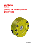
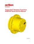
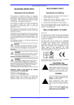
Torque-Hub® Integrated Drive
CT07M2
Assembly-Disassembly Manual
07/02/2010
REV 1
While every precaution has been taken in the preparation of this document, Fairfield Manufacturing
assumes no liability with respect to the use of the documentation described herein, or for any act or
omission of Fairfield concerning this documentation.
Features and specifications are subject to change without notice.
2
Table of Contents
Introduction ................................................................................................................................. 4
Roll and Leak Testing ................................................................................................................. 5
Lubrication Information ............................................................................................................... 6
Main Disassembly....................................................................................................................... 7
Main Assembly ........................................................................................................................... 9
Assembly Drawing……………………………………………………………………………………….11
Parts List..................................................................... ……………………………………………..12
Tool Prints………………………………………………………………………………………………...13
Contact Information .................................................................................................................. 14
Fairfield Manufacturing Company, Inc.
P.O. Box 7940
U.S. 52 South
Lafayette, Indiana 47903
Phone 765-772-4000 Fax 765-772-4001
MMX
3
Introduction
This manual is a step-by-step guide to the disassembly and assembly of Torque-Hub® integrated drive,
and is designed for the customer or shop mechanic who is repairing this particular model of TorqueHub®.
Users of this manual should note that each part mentioned is followed by an identification number
enclosed in parentheses. These part numbers may be referred to in the Parts List section of this
manual and on the illustrated parts breakdown of this unit.
Users should familiarize themselves with the procedures for roll and leak testing found on the following
two pages before starting any repairs.
Standard safety practices should be followed during the disassembly and assembly procedures
described. Safety glasses and safety shoes should be worn, and heavy, heat resistant gloves should
be used when handling heated components. Be especially alert when you see the word CAUTION.
This indicates that a particular operation could cause personal injury if not performed properly or if
certain safety procedures are not followed. The word NOTE is used to bring attention to the user of
certain procedures or helpful hints that will aid in the disassembly and assembly steps.
4
Roll and Leak Testing
Torque-Hub® drives should always be roll and leak tested before full disassembly and after reassembly to ensure that the unit’s gears, bearings, and seals are working properly. The following
information briefly outlines what to look for when performing these tests.
The Leak Test
The purpose of a leak test is to make sure the unit is airtight. To perform the test, first remove one of
the oil fill & check plugs from the housing of the gearbox. Replace the oil fill & check plug with an
adaptor that has an SAE #6 o-ring plug male thread to a pipe nipple, tee, with a 15psi pressure gage,
zero leaks shut off valve and an air line connector. Make sure none of the connections leak. With the
shut off valve in the closed position, connect the air line supply to the air line connector. Crack open the
shut off valve slowly until the pressure on the pressure gage reads 10 psi. Close the shut off valve. If
there is no more than 1 psi pressure decay in 20 minutes then the unit is considered to be sealed. This
standard is for a unit without oil fill. Leaks will most likely occur at the Pipe Plugs, the main seal, or
wherever o-rings or gaskets are located. The exact location of a leak can usually be detected by
brushing a soap and water solution around the main seal and where the o-rings or gaskets meet on the
exterior of the unit and then checking for air bubbles. If a leak is detected in a seal, o-ring, or gasket
the part must be replaced, and the unit rechecked.
The Roll Test
The purpose of the roll test is to determine if the unit’s Gears are rotating freely and properly. The
Gears should rotate in the unit when a constant force is applied to the roll checking apparatus. If more
drag is felt in the Gears only at certain points, then the Gears are not rolling freely and should be
examined for improper installation or defects. Some Gear packages roll with more difficulty than
others. Do not be concerned if the Gears in the unit seem to roll hard as long as they roll with
consistency. THE ROLL TEST OF THIS UNIT IS TO BE PERFORMED AT THE TIME OF
DISASSEMBLY.
5
Lubrication Information
General Properties
The lubricant used in all Torque-Hub® drives should be a petroleum based, non-detergent gear fluid
containing anti-oxidation, anti-foaming and extreme pressure (EP) additives. The lubricant should have
a minimum viscosity index of 90 cst and maintain a minimum viscosity of 40 cst under normal operating
temperature conditions.
Maintenance
An initial oil change should be made after the first 100 hours of operation. Subsequent oil changes
should be made at 1000 hour intervals or annually, whichever comes first. Oil temperature should be
no higher than 160° to 180°F for continuous operation, and no higher than 225°F for intermittent
operation.
Oil Fill Level
When the Torque-Hub® unit is mounted horizontally, the CT07M2 gearboxes should be filled with
27 oz. of 80W90 oil when unit is filled for the 1st time, or whenever unit has been completely
disassembled and rebuilt. For normal oil changes, position fill level line on cover to the
horizontal position and fill to line approximately 27 oz. of 80W90 oil, AGMA GL5 specification or
ISO 220. For operation at extreme ambient conditions above 100°F synthetic oil is
recommended for proper lubrication life at an elevated temperature.
6
Disassembly Procedure
CT07M2 Main Disassembly
1. Perform Leak Test prior to disassembling the unit.
2. Remove Oil Plug (1C), Drain oil from unit. NOTE: Note the condition and volume of oil before
draining.
3.
Remove Retaining Ring (6B) by prying the open end of the retaining ring out of the groove
in the Housing (1G) with a screwdriver, then grasp the loose end with pliers and pull the retaining
ring completely out of the groove.
4. Remove Cover (6A), remove O-ring (17) from groove in the Cover (6A) and discard o-ring.
Note: The unit can be carefully pressurized with air to remove the cover from the unit.
5. Remove Spacer (2) from Cover (6A).
7
6. PERFORM A ROLL TEST :
Remove the Input Shaft (9) and use tool T- 218221 so that the gear portion is in mesh with the input
planet gears (3F). Rotate the Gearbox both clockwise and counterclockwise the same number of
turns as the ratio of the unit. The nominal Gearbox ratio for this unit is 22 to 1.
7. Lift out Input Carrier Subassembly (3).
8. Remove Thrust Washer (11) from counter bore in Output Carrier Subassembly (4).
9. Lift Output Carrier Subassembly (4) from Housing (1G).
10. Remove Lock Nut (1L) with Lock Nut Wrench (T-215480).
11. Remove Housing (1G) from Motor Spindle Subassembly (1A).
12. Remove Face Seal (18) from Housing (1G).
13. Remove Face Seal (18) from Motor Spindle Subassembly.
This concludes the Main Disassembly.
8
Assembly Procedure
CT07M2 Main Assembly
1. Place Motor Spindle Subassembly (1A) on bench with spline end facing up.
2. Using a clean rag and alcohol, clean face seal bore on Motor Spindle Subassembly (1A) and the
rubber ring of the Face Seal (1B). Press the Face Seal (1B) into the seal counter bore of the Motor
Spindle Subassembly (1A) by hand until it is seated.
3. Using a clean tissue remove any debris from the metal surface of the Face Seal (1B). Using a
clean foam brush, apply a light coat of 80W90 oil to the metal surface of the Face Seal (1B).
4. Using a clean rag and alcohol, clean face seal bore on Housing (1G) and the rubber ring of the
Face Seal (1B). Press the Face Seal (1B) into the Housing (1G) seal counter bore by hand until it
is seated.
5. Using a clean tissue remove any debris from the metal surface of the Face Seal (1B). Using a
clean foam brush, apply a light coat of 80W90 oil to the metal surface of the Face Seal (1B).
6. Install the Housing (1G) onto the Motor Spindle Subassembly (1A).
9
7. Install Bearing Nut (1E) with face groove facing out. Torque Bearing Nut (1E) to 150 ft-lbs.
8. Rotate Housing (1G) to seat the bearing, and then torque the Bearing Nut (1E) to 150 ft-lbs. If the
Bearing Nut moves, then rotate the housing again and re-torque the nut to 150 ft-lbs. Repeat this
process until there is no additional movement of the Bearing Nut.
9. Spray inside of the Housing (1G) with a light coat of Rustilo-4140 oil. Being careful not to get any
Rustilo-4140 into the small opening in the Motor Spindle Subassembly (1A). Install Output Carrier
Subassembly (4), by aligning the 2 lugs on the carrier with 2 slots in the Bearing Nut (1E). Check
several orientations of the carrier to fit the slots in the bearing nut. If the Bearing Nut (1E) needs to
be moved to locate the carrier lugs ALWAYS tighten the nut.
10. Using Grease install Thrust Washer (11) onto Output Carrier (4).
11. Spray inside of the unit with a light coat of Rustilo-4140 oil and install Input Carrier Subassembly
(3). Being careful not to get any Rustilo-4140 into the small opening in the Motor Spindle
Subassembly (1A).
12. Place tool T-218221 into mesh with Input Carrier Subassembly planet gears. Roll unit both
directions to check if gears move freely. Remove tool.
13. Lubricate seal diameter of Input Shaft (9) with hydraulic oil. Install Input Shaft (9) using caution to
not cause damage to seal in the Motor/Spindle Subassembly (1A).
14. Apply grease to Spacer (2) and install it into the Cover (6A). Apply grease to O-Ring (17) and install
into the groove in the Cover (6A).
15.
Install Retaining Ring (6B) into groove in the Housing (1G) to retain the Cover (6A). Be
sure the Retaining Ring (6B) is seated.
16. Install all Oil Plugs (1C) and pressure check the unit.
This concludes the Main Assembly.
10
11
Assembly Drawing
12
Parts List
CT07M2
ITEM #
3
4
1G
9
1F
6A
11
1D
15
1B
6B
16
17
2
1E
1A
QTY
1
1
1
1
1
1
1
2
1
1
1
2
1
1
1
1
DESCRIPTION
Input Carrier Subassembly
Output Carrier Subassembly
Housing
Input Shaft
Ring Gear
Cover Plate
Thrust Washer
Tapered Bearing Assembly
I.D. Plate
Face Seal
Internal Retaining Ring
Rivet
O-Ring (-172,8.237,.103)
Spacer
Bearing Nut
Motor/Spindle Subassembly
13
Tool Prints
14
With over 90 years of experience, Fairfield Manufacturing has become the largest U.S. non-captive
producer of Gears, custom Gear assemblies, planetary final drives, and related Gear products. Fairfield
Manufacturing, headquartered in Lafayette, Indiana, is distinguished by our extensive design,
manufacturing, and applications engineering capabilities. Our 500,000 square foot plant is a modern,
fully equipped manufacturing facility that includes a full service heat treat department.
Our philosophy of synchronous engineering is a partnership that matches our best and brightest people
with your people to evaluate your unique requirements, and develop products and assemblies that
meet your needs.
For more information, contact Fairfield today.
Mailing Address:
Fairfield Manufacturing Co., Inc.
U.S. 52 South
P.O. Box 7940
Lafayette IN 47903-7940
Shipping Address:
2309 Concord Rd.
Lafayette, IN 47909
Telephone:
Main
Automated
Voicemail
(765) 772-4000
(765) 772-4002
(765) 772-4003
FAX:
Main
Applications Engineering
Sales and Service
(765) 772-4001
(765) 772-4011
(765) 772-4010
E-mail:
Applications Engineering
Sales
[email protected]
[email protected]
Website:
www.fairfieldmfg.com
15