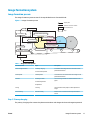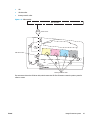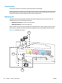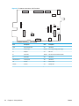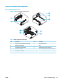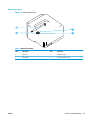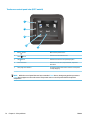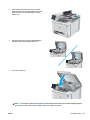
1
Color LaserJet Pro M252
Color LaserJet Pro MFP M277
Troubleshooting manual
M277
www.hp.com/support/colorljM252
www.hp.com/support/colorljMFPM277
For printer part removal and part number
information, see the Repair Manual.
M252n
M252dw
HP Color LaserJet Pro M252 and HP Color
LaserJet Pro MFP M277
Troubleshooting Manual
Copyright and License
© 2015 Copyright Hewlett-Packard
Development Company, L.P.
Reproduction, adaptation, or translation
without prior written permission is prohibited,
except as allowed under the copyright laws.
The information contained herein is subject to
change without notice.
The only warranties for HP products and
services are set forth in the express warranty
statements accompanying such products and
services. Nothing herein should be construed
as constituting an additional warranty. HP shall
not be liable for technical or editorial errors or
omissions contained herein.
Edition 1, 4/2015
Conventions used in this guide
TIP:
Helpful hints or shortcuts.
Reinstallation tip: Reinstallation helpful hints, shortcuts, or considerations.
NOTE:
Information that explains a concept or how to complete a task.
IMPORTANT:
CAUTION:
Information that help the user to avoid potential printer error conditions.
Procedures that the user must follow to avoid losing data or damaging the printer.
WARNING! Procedures that the user must follow to avoid personal injury, catastrophic loss of data, or
extensive damage to the printer.
ENWW
iii
iv
Conventions used in this guide
ENWW
For additional service and support information
HP service personnel, go to the Service Access Work Bench (SAW) at http://h41302.www4.hp.com/km/saw/
home.do.
Channel partners, go to HP Channel Services Network (CNS) at https://h30125.www3.hp.com/hpcsn.
ENWW
●
To access HP PartSurfer information from any mobile device, go to http://partsurfermobile.hp.com/ or
scan the Quick Response (QR) code below.
●
Install and configure
●
Printer specifications
●
Up-to-date control-panel message (CPMD) troubleshooting
●
Solutions for printer issues and emerging issues
●
Remove and replace part instructions and videos
●
Service advisories
●
Warranty & regulatory information
v
vi
For additional service and support information
ENWW
Table of contents
1 Theory of operation ....................................................................................................................................... 1
Related documentation and software ................................................................................................................... 2
Basic operation ...................................................................................................................................................... 3
Sequence of operation ........................................................................................................................ 4
Formatter-control system ..................................................................................................................................... 5
Sleep delay .......................................................................................................................................... 5
Printer job language (PJL) ................................................................................................................... 5
Printer management language (PML) ................................................................................................. 6
Control panel ....................................................................................................................................... 6
Walk-up USB (touchscreen models only) ............................................................................................ 6
Wireless (wireless models only) .......................................................................................................... 6
Low end data model (LEDM) ................................................................................................................ 6
Advanced control language (ACL) overview ........................................................................................ 6
Near field communication (NFC) (wireless models only) .................................................................... 7
CPU ....................................................................................................................................................... 7
Input/output ........................................................................................................................................ 7
USB .................................................................................................................................... 7
USB hosts .......................................................................................................................... 7
10/100 networking ........................................................................................................... 7
Fax (M277 models only) .................................................................................................... 7
Memory ................................................................................................................................................ 7
Firmware ........................................................................................................................... 7
Nonvolatile random access memory (NVRAM) ................................................................. 7
Flash memory ................................................................................................................... 7
Random access memory (RAM) ........................................................................................ 8
HP Memory enhancement technology (MEt) .................................................................... 8
Engine-control system .......................................................................................................................................... 9
Engine control unit (ECU) .................................................................................................................. 10
DC controller ................................................................................................................... 10
High-voltage power supply ............................................................................................ 11
Motors ............................................................................................................................. 11
Fans ................................................................................................................................. 12
ENWW
vii
Solenoids ......................................................................................................................... 12
Switches .......................................................................................................................... 13
Sensors ........................................................................................................................... 14
Low-voltage power supply ................................................................................................................ 15
Overcurrent/overvoltage protection .............................................................................. 15
Low-voltage power supply unit failure detection .......................................................... 15
Engine laser scanner system ............................................................................................................................... 16
Laser failure detection ...................................................................................................................... 16
Image formation system ..................................................................................................................................... 17
Image formation process .................................................................................................................. 17
Step 1: Primary charging ................................................................................................ 17
Step 2: Laser-beam exposure ......................................................................................... 19
Step 3: Development ...................................................................................................... 19
Step 4: Primary transfer ................................................................................................. 20
Step 5: Secondary transfer ............................................................................................. 20
Step 6: Separation ........................................................................................................... 21
Step 7: Fusing .................................................................................................................. 21
Step 8: Drum cleaning ..................................................................................................... 21
Toner cartridges ................................................................................................................................ 23
Design ............................................................................................................................. 23
Memory chip .................................................................................................................... 24
HP Cartridges with JetIntelligence ................................................................................. 24
HP Cartridge Policy ....................................................................................... 24
Anti-theft or cartridge protection ................................................................ 24
Intermediate transfer belt (ITB) assembly ........................................................................................ 24
Engine pickup, feed, and delivery system ........................................................................................................... 26
Priority input slot pickup ................................................................................................................... 29
Cassette pickup ................................................................................................................................. 30
Duplexing unit ................................................................................................................................... 30
Duplex reverse and duplex feed control ........................................................................ 31
Duplex pickup operation ................................................................................................. 31
Jam detection .................................................................................................................................... 32
Scanning and image capture system .................................................................................................................. 33
Automatic document feeder (ADF) system ......................................................................................................... 34
ADF simplex operation ...................................................................................................................... 34
Fax functions and operation (fax models only) .................................................................................................. 35
Computer and network security features ......................................................................................... 35
PSTN operation .................................................................................................................................. 35
Receive faxes when you hear fax tones ............................................................................................ 35
Distinctive ring function .................................................................................................................... 36
Set up the distinctive ring function ................................................................................ 36
viii
ENWW
Fax by using voice over IP (VOIP) services ........................................................................................ 36
The fax subsystem ............................................................................................................................ 37
Fax card in the fax subsystem ........................................................................................................... 37
Safety isolation ............................................................................................................... 37
Safety-protection circuitry ............................................................................................. 37
Data path ......................................................................................................................... 37
Hook state ....................................................................................................................... 38
Downstream device detection ........................................................................................ 38
Hook switch control ........................................................................................................ 38
Ring detect ...................................................................................................................... 38
Line current control ........................................................................................................ 38
Billing or metering tone filters ....................................................................................... 39
Fax page storage in flash memory .................................................................................................... 39
Stored fax pages ............................................................................................................. 39
Advantages of flash memory storage ............................................................................ 39
2 Solve problems ............................................................................................................................................ 41
Troubleshooting process ..................................................................................................................................... 42
Solve problems checklist ................................................................................................................... 42
Print the menu map ........................................................................................................ 43
Print a configuration page .............................................................................................. 43
Print the service page (includes the event log) .............................................................. 44
Determine the problem source ......................................................................................................... 44
Troubleshooting flowchart ............................................................................................. 44
Power subsystem .............................................................................................................................. 45
Power-on checks ............................................................................................................. 45
Power-on troubleshooting overview ........................................................... 45
Control panel checks ......................................................................................................................... 49
Tools for troubleshooting .................................................................................................................................... 50
Individual component diagnostics .................................................................................................... 50
Tools for troubleshooting: LED diagnostics ................................................................... 50
Network port LEDs ....................................................................................... 50
Two-line control panel LEDs ........................................................................ 51
Tools for troubleshooting: Engine diagnostics .............................................................. 51
Engine test .................................................................................................... 51
Diagrams ........................................................................................................................................... 52
Diagrams: Block diagrams .............................................................................................. 52
Sensors and switches ................................................................................... 52
Diagrams: Printed circuit assembly (PCA) connector locations ..................................... 53
Diagrams: Formatter connections ............................................................... 53
Diagrams: DC controller connections ........................................................... 55
ENWW
ix
Diagrams: External plug and port locations ................................................................... 56
Diagrams: Locations of major components ................................................................... 57
Major components (printer base) ................................................................. 57
Motors and fan .............................................................................................. 58
Rollers (printer base) .................................................................................... 59
PCAs (printer base) ....................................................................................... 60
Diagrams: Timing chart .................................................................................................. 61
Diagrams: Circuit diagrams ............................................................................................. 62
Advanced configuration with HP Embedded Web Server (EWS) and HP Device Toolbox
(Windows) .......................................................................................................................................... 63
Print quality troubleshooting tools .................................................................................................. 66
Repetitive defects ruler .................................................................................................. 66
Use a ruler to measure between repetitive defects ..................................... 66
Calibrate the printer to align the colors ......................................................................... 70
Control panel menus ......................................................................................................................... 71
2-line control-panel view (M252n model) ...................................................................... 71
Touchscreen control-panel view (M252dw model) ........................................................ 72
Home screen layout ...................................................................................... 73
Touchscreen control-panel view (M277 models) ........................................................... 74
Home screen layout ...................................................................................... 75
Setup menu ..................................................................................................................... 76
HP Web Services menu ................................................................................. 76
Reports menu ............................................................................................... 77
Self Diagnostics menu .................................................................................. 79
Fax Setup menu ............................................................................................ 79
System Setup menu ..................................................................................... 82
Service menu ................................................................................................ 86
Network Setup menu .................................................................................... 88
Quick Forms menu ........................................................................................ 89
Function specific menus ................................................................................................. 90
USB menu ..................................................................................................... 90
Fax Menu (M277 models only) ..................................................................... 90
Copy menu (M277 models only) ................................................................... 92
Scan menu (M277 models only) ................................................................... 94
Apps .............................................................................................................. 94
Control panel message document (CPMD) ....................................................................................... 95
Control-panel message types ........................................................................................ 95
Control-panel messages and event log entries ............................................................. 95
Alpha Error Messages ................................................................................... 95
49.XX.YY Error Messages ........................................................................... 105
50.XX fuser errors ...................................................................................... 106
x
ENWW
51.XX and 52 Laser/Scanner Errors ........................................................... 107
54.XX Error Messages ................................................................................ 108
55.XXXX Error Messages ............................................................................ 108
57.XX Error Messages ................................................................................ 109
58.XX Error Messages ................................................................................ 109
59.XX Error Messages ................................................................................ 110
79 Errors ..................................................................................................... 111
Tools for troubleshooting: Event log messages ............................................................................. 112
Print an event log .......................................................................................................... 112
View the event log ........................................................................................................ 112
Event-log messages ..................................................................................................... 113
Solve image quality problems ........................................................................................................................... 119
Improve print quality ...................................................................................................................... 119
Repetitive defects ruler ................................................................................................ 119
Print from a different software program ..................................................................... 120
Check the paper-type setting for the print job ............................................................ 120
Check the paper type setting (Windows) ................................................... 120
Check the paper type setting (Mac OS X) ................................................... 120
Check toner-cartridge status ....................................................................................... 121
Print and interpret the print quality page .................................................................... 121
Clean the printer ........................................................................................................... 122
Print a cleaning page .................................................................................. 122
Clean the scanner glass strip and platen ................................................... 123
Visually inspect the toner cartridge ............................................................................. 123
Check paper and the printing environment ................................................................. 124
Step one: Use paper that meets HP specifications .................................... 124
Step two: Check the environment .............................................................. 124
Calibrate the printer to align the colors ....................................................................... 124
Check other print job settings ...................................................................................... 125
Check the EconoMode settings .................................................................. 125
Adjust color settings (Windows) ................................................................ 126
Try a different print driver ............................................................................................ 127
Clean the printer ................................................................................................................................................ 129
Print a cleaning page ....................................................................................................................... 129
Clean the scanner glass strip and platen ........................................................................................ 129
Clean the pickup and separation rollers ......................................................................................... 130
Clean the pickup rollers and separation pad in the document feeder ........................................... 131
Clean the touchscreen ..................................................................................................................... 131
Solve paper-handling problems ........................................................................................................................ 132
Printer feeds incorrect page size .................................................................................................... 132
Printer pulls from incorrect tray ..................................................................................................... 132
ENWW
xi
Printer will not duplex or duplexes incorrectly ............................................................................... 132
Paper does not feed from Tray 2 .................................................................................................... 133
Output is curled or wrinkled ............................................................................................................ 133
Printer does not pick up paper or misfeeds .................................................................................... 134
The printer does not pick up paper .............................................................................. 134
The printer picks up multiple sheets of paper ............................................................. 134
The document feeder jams, skews, or picks up multiple sheets of paper (M277
models) ......................................................................................................................... 135
Paper does not feed automatically .............................................................................. 135
Prevent paper jams ........................................................................................................................................... 136
Clear paper jams ................................................................................................................................................ 137
Introduction ..................................................................................................................................... 137
Experiencing frequent or recurring paper jams? ............................................................................ 137
Paper jam locations ......................................................................................................................... 138
Clear paper jams in the document feeder (M277 models only) ..................................................... 140
Clear paper jams in the single-sheet slot (Tray 1) .......................................................................... 142
Clear paper jams in Tray 2 ............................................................................................................... 144
Clear paper jams in the rear door and the fuser area (simplex models) ........................................ 147
Clear paper jams in the output bin .................................................................................................. 149
Clear paper jams in the duplexer (duplex models) ......................................................................... 150
Solve performance problems ............................................................................................................................ 152
Solve connectivity problems ............................................................................................................................. 153
Solve USB connection problems ..................................................................................................... 153
Solve wired network problems ....................................................................................................... 153
Introduction .................................................................................................................. 153
Poor physical connection .............................................................................................. 153
The computer is using the incorrect IP address for the printer ................................... 153
The computer is unable to communicate with the printer ........................................... 154
The printer is using incorrect link and duplex settings for the network ..................... 154
New software programs might be causing compatibility problems ........................... 154
The computer or workstation might be set up incorrectly .......................................... 154
The printer is disabled, or other network settings are incorrect ................................. 154
Solve wireless network problems ................................................................................................... 154
Introduction .................................................................................................................. 154
Wireless connectivity checklist ..................................................................................... 155
The printer does not print after the wireless configuration completes ...................... 155
The printer does not print, and the computer has a third-party firewall installed ..... 156
The wireless connection does not work after moving the wireless router or printer . 156
Cannot connect more computers to the wireless printer ............................................ 156
The wireless printer loses communication when connected to a VPN ........................ 156
The network does not appear in the wireless networks list ........................................ 156
xii
ENWW
The wireless network is not functioning ...................................................................... 156
Perform a wireless network diagnostic test ................................................................ 157
Reduce interference on a wireless network ................................................................. 157
Service mode functions ..................................................................................................................................... 158
Service menu ................................................................................................................................... 158
Secondary service menu ................................................................................................................. 159
Printer resets ................................................................................................................................... 160
Restore the factory-set defaults .................................................................................. 160
NVRAM initialization ..................................................................................................... 161
Super NVRAM initialization ........................................................................................... 161
Solve fax problems ............................................................................................................................................ 163
Checklist for solving fax problems .................................................................................................. 163
Perform a fax diagnostic test ......................................................................................................... 164
Solve general fax problems ............................................................................................................ 164
Faxes are sending slowly .............................................................................................. 164
Print quality of a photo is poor or prints as a gray box. ............................................... 165
Fax quality is poor ......................................................................................................... 165
You touched the Cancel
button to cancel a fax, but the fax was still sent ............. 166
No fax address book button displays ........................................................................... 166
Not able to locate the fax settings in HP Web Jetadmin .............................................. 166
The header is appended to the top of the page when the overlay option is enabled . 166
A mix of names and numbers is in the recipients box .................................................. 166
A one-page fax prints as two pages ............................................................................. 167
A document stops in the document feeder in the middle of faxing ............................ 167
The volume for sounds coming from the fax accessory is too high or too low ........... 167
Use fax over VoIP networks .......................................................................................... 167
Solve problems receiving faxes ...................................................................................................... 167
Solve problems sending faxes ........................................................................................................ 172
Fax error messages on the control panel ....................................................................................... 173
The No Fax Detected message displays ....................................................................... 173
The Communication error message appears ............................................................... 173
No Dial Tone .................................................................................................................. 174
The Fax is busy message appears ................................................................................ 175
The No fax answer message appears ........................................................................... 175
Document feeder paper jam ......................................................................................... 176
The Fax storage is full message appears ..................................................................... 176
Scanner error ................................................................................................................ 176
The control panel displays a Ready message with no attempt to send the fax .......... 176
The control panel displays the message "Storing page 1" and does not progress
beyond that message ................................................................................................... 177
Faxes can be received, but not sent ............................................................................. 177
ENWW
xiii
Printer is password protected ...................................................................................... 177
Unable to use fax functions from the control panel .................................................... 177
Unable to use speed dials ............................................................................................. 177
Unable to use group dials ............................................................................................. 178
Receive a recorded error message from the phone company when trying to send
a fax ............................................................................................................................... 178
Unable to send a fax when a phone is connected to the printer .................................. 179
Troubleshoot fax codes and trace reports ...................................................................................... 179
View and interpret fax error codes ............................................................................... 179
Fax trace report ............................................................................................................ 180
Fax logs and reports ........................................................................................................................ 180
Print all fax reports ....................................................................................................... 180
Print individual fax reports ........................................................................................... 181
Set the fax error report ................................................................................................. 181
Set the fax-error-correction mode ................................................................................................. 181
Change the fax speed ...................................................................................................................... 182
Use fax on a DSL, PBX, or ISDN system ........................................................................................... 182
DSL ................................................................................................................................ 182
PBX ................................................................................................................................ 182
ISDN ............................................................................................................................... 183
Solve email problems ........................................................................................................................................ 184
Cannot connect to the email server ................................................................................................ 184
Validate the SMTP gateway (Windows) .......................................................................................... 184
Validate the LDAP gateway (Windows) ........................................................................................... 184
Update the firmware ......................................................................................................................................... 185
Method one: Update the firmware using the control panel ........................................................... 185
Method two: Update the firmware using the Firmware Update Utility .......................................... 186
Appendix A Certificates of volatility ............................................................................................................... 187
Certificate of volatility ....................................................................................................................................... 188
Index ........................................................................................................................................................... 193
xiv
ENWW
List of tables
Table 1-1
Sequence of operation .......................................................................................................................................... 4
Table 1-2
Printer motors1 ................................................................................................................................................... 11
Table 1-3
Printer fan ........................................................................................................................................................... 12
Table 1-4
Solenoids ............................................................................................................................................................ 12
Table 1-5
Switches .............................................................................................................................................................. 13
Table 1-6
Sensors ............................................................................................................................................................... 14
Table 1-7
Image formation process ................................................................................................................................... 17
Table 1-8
Switches and sensors for the pickup, feed, and delivery system ...................................................................... 27
Table 1-9
Motors and solenoids for the pickup, feed, and delivery system ...................................................................... 28
Table 2-1
Troubleshooting flowchart ................................................................................................................................. 44
Table 2-2
Formatter connections—M252 models ............................................................................................................. 53
Table 2-3
Formatter connections—M277 models ............................................................................................................. 54
Table 2-4
DC controller connectors .................................................................................................................................... 55
Table 2-5
Major components (printer base) ....................................................................................................................... 57
Table 2-6
Rollers (printer base) .......................................................................................................................................... 59
Table 2-7
Main PCAs (printer base) ..................................................................................................................................... 60
Table 2-8
Repetitive image defects .................................................................................................................................... 66
Table 2-9
HP Web Services menu ....................................................................................................................................... 76
Table 2-10
Reports menu ................................................................................................................................................... 77
Table 2-11
Self Diagnostics menu ...................................................................................................................................... 79
Table 2-12
Fax Setup menu ................................................................................................................................................ 79
Table 2-13
System Setup menu ......................................................................................................................................... 82
Table 2-14
Service menu .................................................................................................................................................... 86
Table 2-15
Network Setup menu ........................................................................................................................................ 88
Table 2-16
Quick Forms menu ............................................................................................................................................ 89
Table 2-17
USB menu ......................................................................................................................................................... 90
Table 2-18
Fax Menu ........................................................................................................................................................... 90
Table 2-19
Copy menu ........................................................................................................................................................ 92
Table 2-20
Scan menu ........................................................................................................................................................ 94
Table 2-21 Event-log messages (X=0: black cartridge, X=1: cyan cartridge, X=2: magenta cartridge, X=3: yellow
cartridge) .............................................................................................................................................................................. 113
Table 2-22
ENWW
Fax event log codes ........................................................................................................................................ 118
xv
Table 2-23
Repetitive image defects ............................................................................................................................... 119
Table 2-24 Solve performance problems ......................................................................................................................... 152
Table 2-25 Service menu .................................................................................................................................................. 158
Table 2-26
Secondary service menu ................................................................................................................................ 159
Table 2-27
Solve problems receiving faxes ..................................................................................................................... 167
Table 2-28
Solve problems sending faxes ....................................................................................................................... 172
xvi
ENWW
List of figures
Figure 1-1
Basic operation .................................................................................................................................................... 3
Figure 1-2
Engine-control system ........................................................................................................................................ 9
Figure 1-3
Engine control unit ............................................................................................................................................ 10
Figure 1-4
High-voltage power supply ............................................................................................................................... 11
Figure 1-5
Low-voltage power supply ............................................................................................................................... 15
Figure 1-6
Laser scanner system ....................................................................................................................................... 16
Figure 1-7
Image-formation process ................................................................................................................................. 17
Figure 1-8
Primary charging ............................................................................................................................................... 18
Figure 1-9
Laser-beam exposure ....................................................................................................................................... 19
Figure 1-10
Development ................................................................................................................................................... 19
Figure 1-11
Primary transfer .............................................................................................................................................. 20
Figure 1-12
Secondary transfer ......................................................................................................................................... 20
Figure 1-13
Separation ....................................................................................................................................................... 21
Figure 1-14
Fusing .............................................................................................................................................................. 21
Figure 1-15
Drum cleaning ................................................................................................................................................. 22
Figure 1-16
Toner cartridge system ................................................................................................................................... 23
Figure 1-17
ITB assembly ................................................................................................................................................... 25
Figure 1-18
Paper path ....................................................................................................................................................... 26
Figure 1-19
Switches and sensors for the pickup, feed, and delivery system .................................................................. 27
Figure 1-20
Motors and solenoids for the pickup, feed, and delivery system .................................................................. 28
Figure 1-21
Duplexing unit controls ................................................................................................................................... 30
Figure 2-1
Engine test page ................................................................................................................................................ 46
Figure 2-2
Engine test page ................................................................................................................................................ 47
Figure 2-3
Engine test page ................................................................................................................................................ 48
Figure 2-4
Engine test page ................................................................................................................................................ 51
Figure 2-5
Sensors and switches ........................................................................................................................................ 52
Figure 2-6
Formatter connections—M252 models ........................................................................................................... 53
Figure 2-7
Formatter connections—M277 models ........................................................................................................... 54
Figure 2-8
DC controller PCA connectors ........................................................................................................................... 55
Figure 2-9
Major components (printer base) ..................................................................................................................... 57
Figure 2-10
Motors and fan ................................................................................................................................................ 58
Figure 2-11
Rollers (printer base) ...................................................................................................................................... 59
ENWW
xvii
Figure 2-12
Main PCAs (printer base) ................................................................................................................................. 60
Figure 2-13
General timing chart ....................................................................................................................................... 61
Figure 2-14
General circuit diagram (printer base) ............................................................................................................ 62
Figure 2-15
Examples of repetitive defects ....................................................................................................................... 67
Figure 2-16
Place the ruler on the page ............................................................................................................................. 68
Figure 2-17
Locate the next repetitive defect ................................................................................................................... 68
Figure 2-18
Determine the defective assembly ................................................................................................................. 69
Figure 2-19
Print quality page ......................................................................................................................................... 122
Figure A-1
Certificate of volatility M252 (1 of 2) .............................................................................................................. 188
Figure A-2
Certificate of volatility M252 (2 of 2) .............................................................................................................. 189
Figure A-3
Certificate of volatility M277 (1 of 2) .............................................................................................................. 190
Figure A-4
Certificate of volatility M277 (2 of 2) .............................................................................................................. 191
xviii
ENWW
1
ENWW
Theory of operation
●
Related documentation and software
●
Basic operation
●
Formatter-control system
●
Engine-control system
●
Engine laser scanner system
●
Image formation system
●
Engine pickup, feed, and delivery system
●
Scanning and image capture system
●
Automatic document feeder (ADF) system
●
Fax functions and operation (fax models only)
1
Related documentation and software
HP service personnel, go to the Service Access Work Bench (SAW) at http://h41302.www4.hp.com/km/saw/
home.do.
Channel partners, go to HP Channel Services Network (CSN) at https://h30125.www3.hp.com/hpcsn.
2
Chapter 1 Theory of operation
ENWW
Basic operation
The printer routes all high-level processes through the formatter, which stores font information, processes
the print image, and communicates with the host computer.
The basic printer operation comprises the following systems:
●
Engine control system
●
Laser scanner system
●
Image-formation system
●
Pickup, feed, and delivery system
●
Integrated scanner system (M277 models only)
Figure 1-1 Basic operation
Laser scanner system
Image-formation system
Engine-control system
Pickup, feed and delivery system
Scanner system (M277 models only)
ENWW
Basic operation
3
Sequence of operation
The DC controller PCA controls the operating sequence, as described in the following table.
Table 1-1 Sequence of operation
Period
Duration
Description
Waiting
From the time the power is turned on,
the door is closed, or when the printer
exits sleep mode until the printer is
ready for printing
●
Heats the fuser film in the fuser
●
Pressurizes the fuser pressure roller
●
Detects the toner cartridges
●
Separates all of the developer rollers from the photosensitive
drums
●
Rotates and stops each motor
●
Rotates and stops the main fan
●
Cleans the intermediate transfer belt (ITB) and secondary
transfer roller
●
Detects cable breakage on the thermistor
●
Detects any residual paper in the engine
●
The printer is in the Ready state
●
The printer enters sleep mode if the sleep command is received
from the formatter
●
The printer calibrates if it is time for an automatic calibration
●
Rotates each motor and the main fan
●
Activates the high-voltage power supply
●
Prepares the laser scanner unit
●
Warms the fuser to the correct temperature
●
Forms the image on the photosensitive drums
●
Transfers the toner to the paper
●
Fuses the toner image onto the paper
●
Moves the last printed sheet into the output bin
●
Stops each motor and the main fan
●
Stops the high-voltage power supply
●
Stops the laser scanner unit
●
Stops the fuser
●
Cleans the ITB and secondary transfer roller
●
If the DC controller receives another print command, the printer
enters the initial rotation period when the last rotation is
complete.
Standby
Initial rotation
Printing
Last rotation
4
From the end of the waiting sequence,
the last rotation until the formatter
receives a print command, or until the
printer is turned off
From the time the formatter receives
a print command until the paper
enters the paper path
From the time the first sheet of paper
enters the paper path until the last
sheet has passed through the fuser
From the time the last sheet of paper
exits the fuser until the motors stop
rotating
Chapter 1 Theory of operation
ENWW
Formatter-control system
The formatter is involved in the following procedures:
●
Controlling the sleep delay function
●
Receiving and processing print data from the various printer inputs
●
Monitoring control-panel functions and relaying printer status information (through the control panel
and the bidirectional input/output)
●
Developing and coordinating data placement and timing with the DC controller PCA
●
Storing font information
●
Communicating with the host computer through the bidirectional interface
The formatter receives a print job from the bidirectional interface and separates it into image information and
instructions that control the printing process. The DC controller PCA synchronizes the image-formation
system with the paper input and output systems, and then signals the formatter to send the print-image
data.
Sleep delay
When the printer is in sleep delay mode, the control-panel backlight is turned off, but the printer retains all
printer settings, downloaded fonts, and macros. The default setting is a 15-minute idle time. The setting can
be changed or turned off from the control panel menus.
The printer exits sleep delay mode and enters the warm-up cycle when any of the following occurs:
●
A print job, valid data, or a PML or PJL command is received at the serial port.
●
The control panel is touched.
●
A document is loaded in the document feeder or the scanner lid is opened.
●
A tray is opened.
TIP: Error messages override the sleep delay message. The printer enters sleep mode at the appropriate
time, but the error message continues to display.
Printer job language (PJL)
Printer job language (PJL) is an integral part of configuration, in addition to the standard printer command
language (PCL). With standard cabling, use PJL to perform a variety of functions.
ENWW
●
Dynamic I/O switching. The printer can be configured with a host on each I/O by using dynamic I/O
switching. Even when the printer is offline, it can receive data from more than one I/O simultaneously,
until the I/O buffer is full.
●
Context-sensitive switching. The printer can automatically recognize the personality (PS or PCL) of each
job and configure itself in that personality.
●
Isolation of print environment settings from one print job to the next. For example, if a print job is sent
to the printer in landscape mode, the subsequent print jobs are printed in landscape mode only if they
are formatted for it.
Formatter-control system
5
Printer management language (PML)
The printer management language (PML) allows remote configuration and status monitoring through the I/O
ports.
Control panel
The formatter sends and receives printer status and command data to and from the control panel.
Walk-up USB (touchscreen models only)
This printer features printing from a USB flash drive. This printer supports printing the following types of files
from the USB flash drive:
●
.pdf
●
.jpg
●
.prn and .PRN
●
.cht and .CHT
●
.pxl
●
.pcl and .PCL
●
.ps and .PS
●
.doc and .docx
●
.ppt and .pptx
When a USB flash drive is inserted into the front of the printer, the control panel displays the USB Flash Drive
menu. The files present on the USB flash drive can be accessed from the control panel. Any files in a
supported format on the USB flash drive can be printed directly from the printer control panel. Pages also can
be scanned and saved to the USB flash drive from the control panel.
Wireless (wireless models only)
Wireless models contain a wireless card to enable 802.11b/g/n wireless communication.
Low end data model (LEDM)
The low-end data model (LEDM) provides one consistent data representation method and defines the
dynamic and capabilities tickets shared between clients and devices, as well as the access protocol, event,
security, and discovery methods.
Advanced control language (ACL) overview
The advanced control language (ACL) is a language that supports printer control and firmware downloads in
printers that support both PJL/PCL and host-based printing. Each sequence of ACL commands must be
preceded by a unified exit command (UEL) and an @PJL ENTER LANGUAGE=ACL command. The ACL sequence
is always followed by a UEL. Any number of commands can be placed between the UELs. The only exception to
these rules is the download command. If a firmware download is completed, the download command must be
the last command in the sequence. It will not be followed by a UEL.
6
Chapter 1 Theory of operation
ENWW
The firmware searches for the UEL sequence when parsing commands. However, while downloading binary
data such as host-based code or NVRAM data the firmware suspends UEL parsing. To handle hosts that
“disappear” during binary sequences, the firmware times out all ACL command sessions. If a timeout occurs
during a non-download command sequence, it is treated as the receipt of a UEL. If a timeout occurs during
firmware download, the printer resets.
Near field communication (NFC) (wireless models only)
This printer supports near field communication (NFC) capabilities. NFC enables an easy one-to-one HP
wireless direct print connection using a simple device-to-device touch. Mobile device users can quickly
connect to the printer and print documents and images from a mobile device, such as a smartphone or tablet,
by touching the device to the NFC icon on the printer.
CPU
The formatter incorporates an 800 MHz processor.
Input/output
The following sections discuss the input and output features of the printer.
USB
The printer includes a universal serial bus (USB) 2.0 connection.
USB hosts
The printer includes USB hosts for USB flash drive and wireless communication control.
10/100 networking
The printer includes a 10/100 network (ethernet) connection.
Fax (M277 models only)
The M277 models include a fax phone line connection.
Memory
If the printer encounters a problem when managing available memory, a clearable warning message displays
on the control panel.
Firmware
Memory on the formatter stores the firmware. A remote firmware upgrade process is used to overwrite and
upgrade the firmware.
Nonvolatile random access memory (NVRAM)
The printer uses nonvolatile memory (NVRAM) to store I/O and information about the print environment
configuration. The contents of NVRAM are retained when the printer is turned off or disconnected.
Flash memory
NOR: Stores microprocessor control programs and internal character sets (fonts).
ENWW
Formatter-control system
7
NAND: Stores fax memory (M277 models only) and driver installation software.
Random access memory (RAM)
The M252n model comes with 128 MB of memory installed. All other models come with 256 MB of memory
installed. The formatter has 256 MB NAND Flash.
HP Memory enhancement technology (MEt)
The HP Memory Enhancement technology (MEt) effectively doubles the standard memory through a variety of
font- and data-compression methods.
NOTE:
8
The MEt is available only in PCL mode; it is not functional when printing in PS mode.
Chapter 1 Theory of operation
ENWW
Engine-control system
The engine-control system receives commands from the formatter and coordinates all the other systems.
The engine-control system contains the following components:
●
Engine control unit: DC controller and high-voltage power supply
●
Low-voltage power supply
●
Fuser control
Figure 1-2 Engine-control system
Formatter-control system
Engine controller
Laser scanner system
DC controller
Image-formation system
High-voltage power supply
Formatter
Fuser control
Low-voltage power supply
Pickup, feed and delivery
system
Scanner system
(M277 models only)
The formatter receives a print job from the bidirectional interface and separates it into image information and
instructions that control the printing process. The DC controller PCA synchronizes the image-formation
system with the paper input and output systems, and then signals the formatter to send the print-image
data.
ENWW
Engine-control system
9
Engine control unit (ECU)
The engine control unit includes the DC controller and the high-voltage power supply.
Figure 1-3 Engine control unit
Engine control unit
Secondary
transfer roller
Cartridge
(Y/M/C/K)
Fan
Motor
High-voltage
power supply
Solenoid
ITB assembly
Switch
Photointerrupter
Sensor
LED
DC controller
Control panel
Fuser
Formatter
Motor
Low-voltage
power supply
Laser scanner
assembly
AC input
DC controller
The DC controller PCA controls the operation of the printer and its components. The DC controller PCA starts
printer operation when the power is turned on and the power supply sends DC voltage to the DC controller
PCA. After the printer enters the standby sequence, the DC controller PCA sends out various signals to operate
motors, solenoids, and other electrical components based on the print command and image data that the
host computer sends.
10
Chapter 1 Theory of operation
ENWW
High-voltage power supply
The DC controller controls the high-voltage power supply to generate high-voltage biases. The high-voltage
power supply generates the high-voltage biases that are applied to the following components:
●
Primary charging roller (in the toner cartridges)
●
Developer roller (in the toner cartridges)
●
Primary transfer roller
●
Secondary transfer roller
●
ITB cleaning brush
●
Static charge eliminator
Figure 1-4 High-voltage power supply
Engine controller
DC controller
High-voltage power supply
T2 bias circuit
Static charge
eliminator bias
circuit
Y
ITB cleaning brush
bias circuit
M
T1 bias and
developing bias
circuit (YMC)
C
ITB cleaning brush
Static charge
eliminator
T2 roller
K
T1 bias and
developing bias
circuit (Bk)
Cartridge
ITB
Motors
The printer includes four motors that affect the paper-feed and image-formation processes.
Table 1-2 Printer motors1
ENWW
Component name
Abbreviation
Components driven
Main motor
M701
●
Photosensitive drum
●
Developer
●
Intermediate transfer belt (ITB)
Engine-control system
11
Table 1-2 Printer motors1 (continued)
Component name
Abbreviation
Components driven
Fuser motor
M702
●
Pressure roller
●
Pressure/release of the pressure roller
●
Output roller
●
Duplex feed roller (duplex models only)
●
Pickup roller
●
Feed roller
●
Feed roller Registration roller
●
Duplex re-pickup roller (duplex models only)
●
Scanner mirror
Pickup motor
Scanner motor
M703
M704
Because the integrated scanner assembly on the M277 models is a whole unit replacement, those motors are not included on this list.
1
The DC controller determines the following motor failures:
●
ITB motor start-up failure
●
ITB motor rotation failure
●
Developer alienation failure
Fans
The printer has one fan for preventing the printer from overheating and for cooling the delivered media.
Table 1-3 Printer fan
Component name
Abbreviation
Cooling area
Type
Speed
Main fan
FM1
●
Toner cartridges
Intake
Full/Half
●
Low-voltage power supply area
The DC controller determines the fan motor1 failure.
Solenoids
The printer has four solenoids. Solenoids are used for printer operation control.
Table 1-4 Solenoids
12
Component abbreviation
Component name
SL711
Developer alienation solenoid
SL712
Pickup solenoid
SL713
Duplex re-pickup solenoid (duplex models only)
SL714
Duplex switchback solenoid (duplex models only)
Chapter 1 Theory of operation
ENWW
Switches
The printer has seven switches. Switches are used for printer operation control.
Table 1-5 Switches
ENWW
Component abbreviation
Component name
SW1
Developer home position detection switch
SW2
Fuser pressure release detection switch
SW3
Rear door switch, left
SW4
Front door switch
SW5
Priority slot media presence detection switch
SW6
Rear door switch, right (simplex models only)
SW601
Power switch
Engine-control system
13
Sensors
The printer has 10 sensors. Sensors are used for remote detection of various functions during printer
operation.
Table 1-6 Sensors
14
Component abbreviation
Component name
SR601
Media width sensor, right
SR602
Media width sensor, left
SR603
Priority slot top sensor
SR604
Registration sensor
SR606
Loop sensor (simplex models only)
SR607
Fuser delivery sensor
SR608
Output sensor (M252dw and M277 models only)
SR616
Loop sensor (duplex models only)
(NA)
Registration density sensor
(NA)
Environment sensor (measures temperature and humidity)
Chapter 1 Theory of operation
ENWW
Low-voltage power supply
The low-voltage power supply converts AC power from the power receptacle into DC power to cover the DC
loads.
Figure 1-5 Low-voltage power supply
AC input
Low-voltage
power supply
DC controller
Fuse
FU101
Power switch
SW601
Rectifying
circuit
PWSV
+24V
generation
circuit
Protection
circuit
+24VA
+3.3VA
+24V
control circuit
+24VB
+24VB1
REM24V
+3.3VC
+3.3V
generation
circuit
+3.3VA
Front door switch
SW4
+3.3VB
+3.3V
control circuit +3.3VD
+3.3VC
+24VB (Nebula only)
Formatter, Contol panel
Overcurrent/overvoltage protection
The low-voltage power supply has a protective function against overcurrent and overvoltage conditions to
prevent failures in the power supply circuit. If an overcurrent or overvoltage event occurs, the system
automatically cuts off the output voltage.
If the DC power is not being supplied from the low-voltage power supply, the protective function might have
activated. In this case, turn off the power switch, and then disconnect the power cord. Do not connect the
power cord or turn the power switch on again until the root cause is found.
Low-voltage power supply unit failure detection
The DC controller determines a low-voltage power supply failure, stops 24V output and notifies the formatter
when it detects that the 24V output is higher than the specified voltage.
ENWW
Engine-control system
15
Engine laser scanner system
The formatter sends video signals to the DC controller, which controls the laser scanner. When the laser
scanner system receives those signals, it converts them to latent images on the photosensitive drum.
Figure 1-6 Laser scanner system
Scanner mirror
Laser assembly
Scanner motor assembly
Beam detect
sensor
Photosensitive drum (Y)
Photosensitive drum (M)
Photosensitive drum (C)
Photosensitive drum (K)
DC controller
Laser failure detection
The optical unit failure detection sensor manages the laser scanner unit failure-detection functions. The DC
controller identifies the laser scanner unit failure and notifies the formatter if the laser scanner unit
encounters the following conditions:
16
●
Scanner motor start-up failure
●
Scanner motor rotational failure
Chapter 1 Theory of operation
ENWW
Image formation system
Image formation process
The image-formation system consists of 10 steps divided into six functional blocks.
Figure 1-7 Image-formation process
: Paper path
: Direction of drum rotation
: Functional block
Delivery
Fusing
: Step
Latent image formation
2. Laser-beam exposure
7. Fusing
1. Priminary charging
Developing
3. Developing
Y
M
C
K
Drum cleaning
Transfer
8. Drum cleaning
6. Separation
4. Primary transfer
5. Secondary transfer
Registration
Pickup
Table 1-7 Image formation process
Functional block
Steps
Description
Latent image formation
1. Primary charging
An invisible latent image forms on the surface of the
photosensitive drums.
2. Laser-beam exposure
Development
3. Development
Toner adheres to the electrostatic latent image on the
photosensitive drums.
Transfer
4. Primary transfer
The toner image transfers to the ITB and later to the
paper.
5. Secondary transfer
6. Separation
Fusing
7. Fusing
The toner fuses to the paper to make a permanent
image.
Drum cleaning
8. Drum cleaning
Residual toner is removed from the photosensitive
drums.
Step 1: Primary charging
The primary-charging roller contacts the photosensitive drum and charges the drum with negative potential.
ENWW
Image formation system
17
Figure 1-8 Primary charging
Primary charging roller
Primary charging bias
Photosensitive drum
18
Chapter 1 Theory of operation
ENWW
Step 2: Laser-beam exposure
The laser beam strikes the surface of the photosensitive drum in the areas where the image will form. The
negative charge neutralizes in those areas, which are then ready to accept toner.
Figure 1-9 Laser-beam exposure
Laser beam
Photosensitive drum
Step 3: Development
Toner acquires a negative charge as the developing cylinder contacts the developing blade. Because the
negatively charged surface of the photosensitive drums have been neutralized where they have been struck
by the laser beam, the toner adheres to those areas on the drums. The latent image becomes visible on the
surface of each drum.
Figure 1-10 Development
Primary charging roller
Primary charging bias
Photosensitive drum
ENWW
Image formation system
19
Step 4: Primary transfer
The positively charged primary-transfer rollers contact the ITB, giving the ITB a positive charge. The ITB
attracts the negatively charged toner from the surface of each photosensitive drum, and the complete toner
image transfers onto the ITB.
Figure 1-11 Primary transfer
Photosensitive
drum
Primary transfer
roller
ITB
Primary transfer bias
Step 5: Secondary transfer
The paper acquires a positive charge from the secondary-transfer roller, and so it attracts the negatively
charged toner from the surface of the ITB. The complete toner image transfers onto the paper.
Figure 1-12 Secondary transfer
ITB
Paper
Secondary transfer
roller
Secondary transfer bias
20
Chapter 1 Theory of operation
ENWW
Step 6: Separation
The stiffness of the paper causes it to separate from the ITB as the ITB bends. The static-charge eliminator
removes excess charge from the paper to make sure that the toner fuses correctly.
Figure 1-13 Separation
ITB
Paper
Static charge eliminator
Secondary transfer
roller
Static charge eliminator bias
Step 7: Fusing
To create the permanent image, the paper passes through heated, pressurized rollers to melt the toner onto
the page.
Figure 1-14 Fusing
Fuser heater
Fuser film
Paper
Pressure roller
Step 8: Drum cleaning
The cleaning blade scrapes the residual toner off the surface of the photosensitive drum, and toner is
deposited in the toner collection box in the cartridge.
ENWW
Image formation system
21
Figure 1-15 Drum cleaning
Cleaning blade
Photosensitive
drum
Residual toner collection box
22
Chapter 1 Theory of operation
ENWW
Toner cartridges
The printer has four toner cartridges, one for each color: cyan, magenta, yellow, and black.
Design
Each toner cartridge is filled with toner and consists of the following components:
●
Photosensitive drum
●
Developer
●
Primary-charging roller
●
Memory chip
The DC controller rotates the drum motor to drive the photosensitive drum, developing roller, and the
primary-charging roller.
Figure 1-16 Toner cartridge system
DC controller
Memory chip
SW1
Cartridge
M701
Developer roller
Primary charging
roller
Developer
Photosensitive drum
ENWW
Image formation system
23
Memory chip
The memory chip is non-volatile memory that stores information about the usage of the toner cartridge and
helps protect the customer from counterfeit cartridges. This chip is also used to detect the presence of a
cartridge within the printer or when a cartridge is installed in the wrong slot. The printer reads and writes the
data in the memory chip.
HP Cartridges with JetIntelligence
HP Cartridges with JetIntelligence supports two features for managing toner cartridges.
●
The HP Cartridge Policy feature allows customers to specify the use of only genuine HP toner cartridges
in the printer.
●
The anti-theft feature enables locking a cartridge to a specific printer or fleet of printers.
HP Cartridge Policy
The genuine HP Cartridge Policy feature allows a customer to specify that only genuine HP supplies can be
used in a printer. If anything but a genuine HP supply is installed, the printer will not print. This feature is
disabled by default, and can be enabled or disabled from the control panel, the HP Embedded Web Server
(EWS), or HP Web Jetadmin.
If a genuine HP cartridge has passed the low state and is installed in a printer that has this feature enabled,
the printer will display an Unauthorized Cartridge message on the control panel and will not print.
If a non-HP toner cartridge is used in a printer with this feature enabled, the message Unauthorized
Cartridge appears on the control-panel display and the printer will not print.
NOTE: If a customer suspects they have a counterfeit cartridge, they should report it by going to
www.hp.com/go/anticounterfeit and selecting Report now.
Anti-theft or cartridge protection
The toner cartridge anti-theft feature allows a customer to configure the printer to automatically lock toner
cartridges to a specific printer or fleet of printers when they are installed. A locked toner cartridge will work
only in the specified printer or fleet of printers. This feature prevents toner cartridges from being stolen and
used in another printer, or from being moved from an authorized printer to an unauthorized printer. This
feature is disabled by default. Cartridge protection to a single printer can be enabled or disabled from the
control panel or the HP Embedded Web Server (EWS). Cartridge protection for a printer fleet can be enabled
only by using HP Web Jetadmin.
When the anti-theft feature is enabled, the toner cartridge in a printer will only work in the specified printer or
fleet of printers. If a locked toner cartridge is moved to another printer, the cartridge will not print and the
message Protected Cartridge appears on the control-panel display.
NOTE: When a toner cartridge is locked to a specific printer or fleet of printers, it cannot be unlocked. This is
a permanent operation.
Intermediate transfer belt (ITB) assembly
The ITB assembly accepts the toner images from the photosensitive drums and transfers the completed
image to the paper. The ITB unit has these main components:
24
Chapter 1 Theory of operation
ENWW
●
ITB
●
ITB drive roller
●
Primary transfer roller
Figure 1-17 ITB assembly
DC controller
M701
Main motor
ITB drive roller
ITB
Primary transfer roller
The main motor drives the ITB drive roller, which rotates the ITB. The ITB motion causes the primary transfer
rollers to rotate.
ENWW
Image formation system
25
Engine pickup, feed, and delivery system
The pickup, feed, and delivery system uses a series of rollers to move the paper through the printer. The
pickup, feed and delivery system consists of following components:
●
Pickup-and-feed block: From each pickup source to the fuser inlet
●
Fuser-and-delivery block: From the fuser to the delivery destination
●
Duplex block (duplex models only): From the duplex switch back unit to duplex re-pickup unit
Figure 1-18 Paper path
Simplex paper path
Duplex paper path
Duplex block
Fuser-and-delivery block
Pickup-and-feed block
26
Chapter 1 Theory of operation
ENWW
Figure 1-19 Switches and sensors for the pickup, feed, and delivery system
SR608
SR607
SR606
SR616
SR604
SW5
SR603
SR601
SR602
Table 1-8 Switches and sensors for the pickup, feed, and delivery system
ENWW
Abbreviation
Component
SR601
Media width sensor, right
SR602
Media width sensor, left
SR603
Priority slot top of page (TOP) sensor
SR604
Registration sensor
SR606
Loop sensor (simplex models only)
SR607
Fuser delivery sensor
SR608
Output sensor (M252dw and M277 models only)
SR616
Loop sensor (duplex models only)
SW5
Priority slot media-presence switch
Engine pickup, feed, and delivery system
27
Figure 1-20 Motors and solenoids for the pickup, feed, and delivery system
M702
SL713
SL714
M701
SL712
M703
Table 1-9 Motors and solenoids for the pickup, feed, and delivery system
28
Abbreviation
Component
M701
Main motor
M702
Fuser motor
M703
Pickup motor
SL712
Cassette pickup solenoid
SL713
Duplex re-pickup solenoid (duplex models only)
SL714
Duplex switchback solenoid (duplex models only)
Chapter 1 Theory of operation
ENWW
Priority input slot pickup
The priority input slot paper-presence sensor detects whether paper is in the tray. If no paper is present, the
DC controller notifies the formatter. The print operation is not performed until paper is in the slot.
The sequence of steps for the priority input slot pickup operation is as follows:
ENWW
1.
After receiving a print command from the formatter, the DC controller reverses the pickup motor, which
causes the priority input slot separation roller to rotate.
2.
The DC controller turns on the priority input slot pickup solenoid, causing the pickup roller to rotate, and
paper is picked from the stack.
3.
The priority input slot separation roller isolates a single sheet of paper in case more than one sheet was
picked. The single sheet of paper is fed into the printer. This mechanism is the same as for the Tray 2
cassette pickup operation.
Engine pickup, feed, and delivery system
29
Cassette pickup
The sequence of steps for the cassette tray pickup operation is the following:
After receiving a print command from the formatter, the DC controller rotates the pickup motor, which causes
the lifting mechanism to lift the paper stack against the pick roller, at which time the cassette pickup roller,
cassette feed roller, and cassette separation roller rotate to feed the sheet.
Duplexing unit
The duplexing unit reverses the paper and feeds it through the paper path to print the second side. The
duplexing unit consists of the following components:
●
Duplexing-reverse unit: Located on top of the printer
●
Duplexing-feed unit: Located on the right side
The DC controller controls the operational sequence of the duplex block. The DC controller drives each load,
such as motors, solenoid, and clutch, depending on the duplex-reverse unit and duplex-feed unit controls.
Figure 1-21 Duplexing unit controls
M702
SL713
SL714
M701
SL712
M703
30
Chapter 1 Theory of operation
ENWW
Duplex reverse and duplex feed control
The duplexing reverse procedure pulls the paper into the duplexing unit after it exits the fuser. The duplexing
feed procedure moves the paper through the duplexer so it can enter the printer paper path to print the
second side of the page.
1.
After the first side has printed, the duplexing flapper solenoid opens, which creates a paper path into the
duplexing-reverse unit.
2.
After the paper has fully entered the duplexing-reverse unit, the duplexing-reverse motor reverses and
directs the paper into the duplexing-feed unit.
3.
The duplexing re-pickup motor and duplexing feed motor move the paper into the duplexing repickup
unit.
4.
To align the paper with the toner image on the ITB, the duplexing re-pickup motor stops and the paper
pauses.
5.
The paper re-enters the paper path, and the second side prints.
Duplex pickup operation
The printer has the following two duplex-media-feed modes depending on the paper sizes:
ENWW
●
One-sheet mode: Prints one sheet that is printed on two sides in one duplex print operation
●
Two-sheet mode: Prints two sheets that are printed on two sides in one duplex print operation
Engine pickup, feed, and delivery system
31
Jam detection
The printer uses the following sensors to detect the presence of media and to check whether media is being
fed correctly or has jammed:
●
Priority slot top-of-page (TOP) sensor—SR603
●
Media width sensor, right—SR601
●
Media width sensor, left—SR602
●
Registration sensor—SR604
●
Loop sensor—SR606 (simplex models) or SR616 (duplex models)
●
Fuser delivery sensor—SR607
●
Output sensor (M252dw and M277 models)—SR608
The printer detects the following jams:
32
●
No pick jam 1
●
No pick jam 2
●
Pickup stay jam 1
●
Fuser delivery delay jam 1
●
Fuser delivery stay jam 1
●
Residual paper jam 1
●
Residual paper jam 2
●
Residual paper jam 3
●
Residual paper jam 4
●
Door open jam 1
●
Fuser wrapping jam 1
●
Duplex re-pickup jam 1 (simplex models)
●
Delivery delay jam 1 (M252dw and M277 models)
●
Delivery stay jam 1 (M252dw and M277 models)
Chapter 1 Theory of operation
ENWW
Scanning and image capture system
The flatbed image scanner captures an electronic image of the document on the glass. The scanner does this
by illuminating the document with LEDs (red, green, and blue) and capturing the image in the image sensor to
create an electronic format of the document. The flatbed scanner consists of three main elements.
●
CIS scanner
The CIS (contact image sensor) scanner captures an image using the printer's optical path. Red, green,
and blue LEDs sequentially illuminate a small strip of the document (often called a raster line), and the
optical system captures each color in a single row of CCD sensors that cover the entire page width.
Because only one color is captured for each line per exposure, the three colors are recombined
electronically to create the full color image. For monochromatic scans or copies, all three LEDs are
illuminated to create a white light for the scan so the raster line can be captured in one exposure.
●
Mechanical drive system
The drive system moves the CIS scanner along the document length to create the image. In this printer,
the drive system consists of a small DC motor with an optical encoder, a drive belt, and a guide rod. The
speed of the drive system is proportional to the scan resolution (300 ppi is much faster than 1200 ppi)
and also proportional to the type of scan (color scans are slower than monochromatic scans).
●
Image processing system (formatter)
The formatter processes the scanner data into either a copy or a scan to the computer. For copies, the
image data is sent directly to the printer without being transmitted to the computer. Depending on user
selections for the copy settings, the formatter enhances the scanner data significantly before sending it
to the printer. Image data is captured at 300 ppi for copies and is user selectable for scans to the
computer. Each pixel is represented by 8 bits for each of the three colors (256 levels for each color), for a
total of 24 bits per pixel (24-bit color).
ENWW
Scanning and image capture system
33
Automatic document feeder (ADF) system
ADF simplex operation
The ADF will not function when the ADF cover is open. The paper path is incomplete if the ADF cover is lifted
from the glass.
When the printer duplexes from the ADF, the paper moves through one time, because the ADF has a CIS
scanner for side two which is scanned simultaneously with side one.
The standard operation of the ADF consists of the standby (paper loading) mode, pick, feed, and lift steps:
●
Standby (paper-loading) mode
In standby mode, the lift plate is in the down position. When a document is loaded into the input tray,
the paper-present sensor detects its presence.
When a copy/scan is initiated, the ADF motor engages the gear train and raises the lift plate until the
document makes contact with the pick roller. The ADF then begins the pick, feed, and home sequence.
●
Pick
The pick roller rotates and moves one or more sheets forward into the ADF where the sheets engage
with the separation roller. The separation roller contacts the ADF separation pad, which separates
multiple sheets into single sheets.
●
Feed
The single sheet continues through the ADF paper path (aided by the pre-scan rollers) until the leading
edge of the page activates the top-of-form sensor. Activation of this sensor initiates the scan process,
and the scanner acquires the image as the document moves over the ADF glass. The post-scan rollers
then eject the sheet into the output area. The pick and feed steps are repeated as long as paper is
detected by the paper-present sensor.
●
Home
When the form sensor detects the trailing edge of the last page, the last sheet is ejected and the motor
turns on a sequence that rests the separation floor back down in standby mode, which allows it to detect
when more media is loaded.
Note that the ADF will not function when the ADF door is open.
34
Chapter 1 Theory of operation
ENWW
Fax functions and operation (fax models only)
The following sections describe the printer fax capabilities.
Computer and network security features
The printer can send and receive fax data over telephone lines that conform to public switch telephone
network (PSTN) standards. The secure fax protocols make it impossible for computer viruses to be
transferred from the telephone line to a computer or network.
The following printer features prevent virus transmission:
●
No direct connection exists between the fax line and any devices that are connected to the USB or
Ethernet ports.
●
The internal firmware cannot be modified through the fax connection.
●
All fax communications go through the fax subsystem, which does not use Internet data-exchange
protocols.
PSTN operation
The PSTN operates through a central office (CO) that generates a constant voltage on the TIP and RING wires
(48 V, usually). A device goes on-hook by connecting impedance (such as 600 ohms for the U.S.) across the
TIP and RING so that a line current can flow. The CO can detect this current and can send impulses like dial
tones. The printer generates more signaling tones, such as dialing digits, to tell the CO how to connect the
call. The printer can also detect tones, such as a busy tone from the CO, that tell it how to behave.
When the call is finally connected, the CO behaves like a piece of wire connecting the sender and receiver. This
is the period during which all of the fax signaling and data transfer occurs. When a call is completed, the
circuit opens again and the line-current flow ceases, removing the CO connection from both the sender and
the receiver.
On most phone systems, the TIP and RING signals appear on pins 3 and 4 of the RJ-11 modular jack (the one
on the fax card, as defined in the common 6 wire RJ standard). These two signals do not have to be polarized
because all of the equipment works with either TIP or RING on one pin and the other signal on the other pin.
This means that cables of either polarity can interconnect and still work.
These basic functions of PSTN operation are assumed in the design of the fax subsystem. The printer
generates and detects the signaling tones, currents, and data signals that are required to transmit and
receive faxes using the PSTN.
Receive faxes when you hear fax tones
In general, incoming faxes to the printer are automatically received. However, if other devices are connected
to the same phone line, the printer might not be set to answer automatically.
If the printer is connected to a phone line that receives both fax and phone calls, and you hear fax tones when
you answer the extension phone, receive the fax in one of two ways:
ENWW
●
If you are near the printer, press Start Fax on the control panel.
●
Press 1-2-3 in sequence on the extension phone keypad, listen for fax transmission sounds, and then
hang up.
Fax functions and operation (fax models only)
35
NOTE: In order for the 1-2-3 sequence to work, the extension phone setting must be set to On in the
Fax Setup menu.
Distinctive ring function
Distinctive ring is a service that a telephone company provides. The distinctive ring service allows three phone
numbers to be assigned to one phone line. Each phone number has a distinctive ring. The first phone number
has a single ring, the second phone number has a double ring, and the third phone number has a triple ring.
NOTE: The printer has not been tested with all of the distinctive-ring services that telephone companies
provide in all countries/regions. HP does not guarantee that the distinctive-ring function will operate correctly
in all countries/regions. Contact the local phone service provider for assistance.
Set up the distinctive ring function
1.
Open the Setup menu.
2.
Open the Fax Menu menu.
3.
Select the Basic Setup menu.
4.
Select the Distinctive Ring setting.
5.
Use the arrow buttons to select one of the following options:
●
All Rings (default setting)
●
Single
●
Double
●
Triple
●
Double and Triple
Fax by using voice over IP (VOIP) services
Voice over IP (VoIP) services provide normal telephone service, including long distance service through a
broadband Internet connection. These services use packets to break up the voice signal on a telephone line
and transmit it digitally to the receiver, where the packets are reassembled. The VoIP services are often not
compatible with fax machines. The VoIP provider must state that the service supports fax over IP services.
Because the installation process varies, the VoIP service provider will have to assist in installing the printer
fax component.
Although a fax might work on a VoIP network, it can fail when the following events occur:
●
Internet traffic becomes heavy and packets are lost.
●
Latency (the time it takes for a packet to travel from its point of origin to its point of destination)
becomes excessive.
If you experience problems using the fax feature on a VoIP network, make sure that all of the printer cables
and settings are correct. Configuring the Fax Speed setting to Medium(V.17) or Slow(V.29) can also improve
your ability to send a fax over a VoIP network.
If you continue to have problems faxing, contact your VoIP provider.
36
Chapter 1 Theory of operation
ENWW
The fax subsystem
The formatter, fax card, firmware, and software all contribute to the fax functionality. The designs of the
formatter and fax card, along with parameters in the firmware, determine the majority of the regulatory
requirements for telephony on the printer.
The fax subsystem is designed to support V.34 fax transmission, low speeds (such as V.17 fax), and older fax
machines.
Fax card in the fax subsystem
Two versions of the fax card are used in the printer. One is used in the North American, South American, and
Asian countries/regions. The other is used primarily in European countries/regions.
The fax card contains the modem chipset (DSP and CODEC) that controls the basic fax functions of tone
generation and detection, along with channel control for fax transmissions. The CODEC and its associated
circuitry act as the third-generation silicon data access arrangement (DAA) to comply with worldwide
regulatory requirements.
The only difference between the two versions is that each version is compliant with the 2/4-wire phone jack
system from the respective country/region.
Safety isolation
The most important function of the fax card is the safety isolation between the high-voltage, transient-prone
environment of the telephone network (TNV [telephone network voltage]) and the low-voltage analog and
digital circuitry of the formatter (SELV [secondary extra-low voltage]). This safety isolation provides both
customer safety and printer reliability in the telecom environment.
Any signals that cross the isolation barrier do so magnetically. The breakdown voltage rating of barriercritical components is greater than 5 kV.
Safety-protection circuitry
In addition to the safety barrier, the fax card protects against over-voltage and over-current events.
Telephone over-voltage events can be either differential mode or common mode. The event can be transient
in nature (a lightning-induced surge or ESD) or continuous (a power line crossed with a phone line). The fax
card protection circuitry provides margin against combinations of over-voltage and overcurrent events.
Common mode protection is provided by the selection of high-voltage-barrier critical components
(transformer and relay). The safety barrier of the fax card PCB traces and the clearance between the fax card
and surrounding components also contribute to common mode protection.
A voltage suppressor (a crowbar-type thyristor) provides differential protection. This device becomes low
impedance at approximately 300 V differential, and crowbars to a low voltage. A series thermal switch works
in conjunction with the crowbar for continuous telephone line events, such as crossed power lines.
All communications cross the isolation barrier magnetically. The breakdown voltage rating of barrier-critical
components is greater than 5 kV.
Data path
TIP and RING are the two-wire paths for all signals from the telephone network. All signaling and data
information comes across them, including fax tones and fax data.
ENWW
Fax functions and operation (fax models only)
37
The telephone network uses DC current to determine the hook state of the telephone, so line current must be
present during a call. The silicon DAA provides a DC holding circuit to keep the line current constant during a
fax call.
The silicon DAA converts the analog signal to a digital signal for DSP processing, and also converts the digital
signal to an analog signal for transmitting data through a telephone line.
The magnetically coupled signals that cross the isolation barrier go through either a transformer or a relay.
The DSP in the fax card communicates with the ASIC in the formatter using the high-speed serial interface.
Hook state
Another magnetically coupled signal is the control signal that disconnects the downstream telephone devices
(such as a phone or answering machine). A control signal originating on the DSP can change the relay state,
causing the auxiliary jack (downstream jack) to be disconnected from the telephone circuit.
The printer takes control of calls that it recognizes as fax calls. If the printer does not directly pick up the call,
it monitors incoming calls for the fax tone or for the user to direct it to receive a fax. This idle mode is also
called eavesdropping. This mode is active when the printer is on-hook but current exists in the downstream
phone line because another device is off-hook. During eavesdropping, the receive circuit is enabled but has a
different gain from the current that is generated during normal fax transmissions.
The printer does not take control of the line unless it detects a fax tone or the user causes it to connect
manually. This feature allows the user to make voice calls from a phone that is connected to the printer
without being cut off if a fax is not being received.
Downstream device detection
The line voltage monitoring module of the silicon DAA can detect the line state as well as the downstream
device. It tells DSP via DIB that an active device (telephone, modem, or answering machine) is connected to
the auxiliary port on the printer (the right side of the dual RJ-11 jack). The DSP uses the signal to ensure that
the printer does not go off-hook (and disconnects a downstream call) until it has been authorized to do so (by
a manual fax start or the detection of the appropriate tones).
Hook switch control
In the silicon DAA the CODEC controls the hook switch directly. The CODEC is activated when it receives
commands from the DSP. When the circuit is drawing DC current from the central office it is considered offhook. When no DC current flows the state is considered on-hook.
Ring detect
Ring detect is performed by the line voltage monitoring module of the silicon DAA, and is a combination of
voltage levels and cadence (time on and time off). Both must be present to detect a valid ring. The CODEC
works with DSP as well as the firmware to determine if an incoming signal is an answerable ring.
Line current control
The DC current from the CO needs to have a path to flow from TIP to RING. The DC impedance emulation line
modulator and DC terminations modules in the silicon DAA act as a DC holding circuit, and work with the
firmware to achieve the voltage-current characteristic between TIP and RING. The impedance (the currentvoltage characteristic) changes corresponding to certain special events, such as pulse dialing or when the
printer goes on-hook.
38
Chapter 1 Theory of operation
ENWW
Billing or metering tone filters
Switzerland and Germany provide high-frequency AC signals on the phone line in order to bill customers.
A filter in a special fax cable (for certain countries/regions), can filter these signals. Because these billing
signals are not used in the U.S., these filters are not present in the U.S. fax cable.
To obtain a special fax cable, contact your local telephone service provider.
Fax page storage in flash memory
Fax pages are the electronic images of the document page. They can be created in any of three ways: scanned
to be sent to another fax machine, generated to be sent by the computer, or received from a fax machine to be
printed.
The printer stores all fax pages in flash memory automatically. After these pages are written into flash
memory, they are stored until the pages are sent to another fax machine, printed on the printer, transmitted
to the computer, or erased by the user.
These pages are stored in flash memory, which is the nonvolatile memory that can be repeatedly read from,
written to, and erased. The printer has 8 MB of flash memory, of which 7.5 MB is available for fax storage. The
remaining 0.5 MB is used for the file system and reclamation. Adding RAM does not affect the fax page
storage because the printer does not use RAM for storing fax pages.
Stored fax pages
The user can reprint stored fax receive pages in case of errors. For a fax send, the printer will resend the fax in
case of errors. The printer will resend stored fax pages after a busy signal, communication error, no answer, or
power failure. Other fax devices store fax pages in either normal RAM or shortterm RAM. Normal RAM
immediately loses its data when power is lost, while short-term RAM loses its data about 60 minutes after
power failure. Flash memory maintains its data for years without any applied power.
Advantages of flash memory storage
Fax pages that are stored in flash memory are persistent. They are not lost as a result of a power failure, no
matter how long the power is off. Users can reprint faxes in case the print cartridge runs out of toner or the
printer experiences other errors while printing faxes.
The printer also has scan-ahead functionality that makes use of flash memory. Scan-ahead automatically
scans pages into flash memory before a fax job is sent. This allows the sender to pick up the original
document immediately after it is scanned, eliminating the need to wait until the fax transmission is complete.
Because fax pages are stored in flash memory rather than RAM, more RAM is available to handle larger and
more complicated copy and print jobs.
ENWW
Fax functions and operation (fax models only)
39
40
Chapter 1 Theory of operation
ENWW
2
ENWW
Solve problems
●
Troubleshooting process
●
Tools for troubleshooting
●
Solve image quality problems
●
Clean the printer
●
Solve paper-handling problems
●
Prevent paper jams
●
Clear paper jams
●
Solve performance problems
●
Solve connectivity problems
●
Service mode functions
●
Solve fax problems
●
Solve email problems
●
Update the firmware
41
Troubleshooting process
Solve problems checklist
If the printer is not correctly functioning, complete the steps (in the order given) in the following checklist. If
the printer fails a checklist step, follow the corresponding troubleshooting suggestions for that step. If a
checklist step resolves the problem, skip the remaining checklist items.
1.
2.
Make sure that the printer is set up correctly.
a.
Press the power button to turn on the printer or to deactivate the Auto-Off mode.
b.
Check the power-cable connections.
c.
Make sure that the line voltage is correct for the printer power configuration. See the label that is
on the printer for voltage requirements. If you are using a power strip and its voltage is not within
specifications, plug the printer directly into the wall. If it is already plugged into the wall, try a
different outlet.
Check the cable connections.
a.
Check the cable connection between the printer and the computer. Make sure that the connection
is secure.
b.
Make sure that the cable itself is not faulty, by using a different cable if possible.
c.
Check the network connection: Make sure that the network light is lit. The network light is next to
the network port on the back of the printer.
If the printer remains unable to connect to the network, uninstall and then reinstall the printer. If
the error persists, contact a network administrator.
3.
Check to see if any messages appear on the control panel.
4.
Make sure that the paper you are using meets specifications.
5.
Make sure that the paper is loaded correctly in the input tray.
6.
Make sure that the printer software is installed correctly.
7.
Verify that you have installed the printer driver for this printer, and that you are selecting this printer
from the list of available printers.
8.
Print a configuration page.
a.
2-line control panels: On the printer control panel, press the OK button.
Touchscreen control panels: From the Home screen on the printer control panel, touch the Setup
button.
42
b.
Open the Reports menu.
c.
Select Configuration Report.
Chapter 2 Solve problems
ENWW
After printing the configuration page, check the following:
9.
a.
If the page does not print, verify that the input tray contains paper and that the paper is properly
loaded.
b.
Make sure that each toner cartridge is installed correctly.
c.
If the page jams in the printer, clear the jam.
d.
If the print quality is unacceptable, complete the following steps:
●
Verify that the print settings are correct for the paper you are using.
●
Solve print-quality problems.
Print a small document from a different program that has printed in the past. If this solution works, then
the problem is with the program you are using. If this solution does not work (the document does not
print), complete these steps:
a.
Try printing the job from another computer that has the printer software installed.
b.
Check the cable connection. Direct the printer to the correct port, or reinstall the software,
selecting the connection type you are using.
Print the menu map
To more easily navigate individual settings, print a report of the complete printer menus.
1.
2-line control panels: On the printer control panel, press the OK button.
Touchscreen control panels: From the Home screen on the printer control panel, touch the Setup
button.
2.
Open the Reports menu.
3.
Select Menu Structure.
Print a configuration page
Print a configuration page to test the printer.
1.
2-line control panels: On the printer control panel, press the OK button.
Touchscreen control panels: From the Home screen on the printer control panel, touch the Setup
button.
ENWW
2.
Open the Reports menu.
3.
Select Configuration Report.
Troubleshooting process
43
Print the service page (includes the event log)
Printing the service page provides a list of printer settings that might be helpful in the troubleshooting
process, as well as the event log, which stores the last 10 error events that the printer experienced.
1.
2-line control panels: On the printer control panel, press the OK button.
Touchscreen control panels: From the Home screen on the printer control panel, touch the Setup
button.
2.
Open the Reports menu.
3.
Select the Service Page option to print the report.
The event log is located in the lower right-hand corner of the service page.
Determine the problem source
When the printer malfunctions or encounters an unexpected situation, the printer control panel alerts the
user to the situation. This section contains a pre-troubleshooting checklist to filter out many possible causes
of the problem. Use the troubleshooting flowchart to help diagnose the root cause of the problem. The
remainder of this chapter provides steps for correcting problems.
●
Use the troubleshooting flowchart to pinpoint the root cause of hardware malfunctions. The flowchart
provides guides to the sections of this chapter that contain steps to correct the malfunction.
Before beginning any troubleshooting procedure, check the following issues:
●
Are supply items within their rated life?
●
Does the configuration page reveal any configuration errors?
NOTE:
The customer is responsible for checking supplies and for using supplies that are in good condition.
Troubleshooting flowchart
This flowchart highlights the general processes to follow to quickly isolate and solve printer hardware
problems.
Each row depicts a major troubleshooting step. Follow a “yes” answer to a question to proceed to the next
major step. A “no” answer indicates that more testing is needed. Go to the appropriate section in this chapter,
and follow the instructions there. After completing the instructions, go to the next major step in this
troubleshooting flowchart.
Table 2-1 Troubleshooting flowchart
1
Power on
Is the printer on and does a readable message
display?
Yes
2
Control panel
messages
44
No
Does the message Ready display on the control
panel?
Yes
Chapter 2 Solve problems
Follow the power-on troubleshooting checks.
After the control panel display is functional, see step 2.
After the errors have been corrected, go to step 3.
No
ENWW
Table 2-1 Troubleshooting flowchart (continued)
3
Print the service page to view the event log to
see the history of errors with this printer.
Event log
Does the service page print?
Yes
No
If the service page does not print, check for error messages.
If paper jams inside the printer, see the jams section of this manual.
If error messages display on the control panel when trying to print a
service page, see the control panel message section of this manual.
After successfully printing and evaluating the event log, see step 4.
4
Information pages
Open the Reports menu and print the
configuration page to verify that all the
accessories are installed.
Are all the accessories installed?
Yes
5
Print quality
6
Interface
After evaluating the configuration pages, see step 5.
No
Does the print quality meet the customer's
requirements?
Yes
If accessories that are installed are not listed on the configuration
page, remove the accessory and reinstall it.
No
Compare any print defects with the repetitive defect ruler in this
manual.
After the print quality is acceptable, see step 6.
Can the customer print successfully from the
host computer?
Verify that all I/O cables are connected correctly and that a valid
IP address is listed on the HP Jetdirect configuration page.
Yes. This is the end of
the troubleshooting
process.
If error messages display on the control panel when trying to print an
event log, see the control-panel message section of this manual.
No
When the customer can print from the host computer, this is the end of
the troubleshooting process.
Power subsystem
Power-on checks
The basic printer functions should start up when the printer is connected into an electrical outlet and the
power switch is pushed to the on position. If the printer does not start, use the information in this section to
isolate and solve the problem.
If the control panel display remains blank, random patterns display, or asterisks remain on the control panel
display, perform power-on checks to find the cause of the problem.
Power-on troubleshooting overview
During normal operation, a cooling fan begins to spin briefly after the printer power is turned on. Place a hand
over the fan intake vents located on the right-side cover. When the fan is correctly operating, air passing into
the printer is felt. Lean close to the printer to hear the fan operating. If the fan is operating, the dc side of the
power supply is functioning.
After the fan is operating, the main motor turns on (unless the top cover is open, a jam condition is sensed, or
the paper-path sensors are damaged). Visually and audibly determine that the main motor is turned on.
If the fan and main motor are operating correctly, the next troubleshooting step is to isolate print engine,
formatter, and control panel problems. Perform an engine test. If the formatter is damaged, it might interfere
with the engine test. If the engine-test page does not print, try removing the formatter, and then performing
the engine test again. If the engine test is then successful, the problem is almost certainly with the formatter,
the control panel, or the cable that connects them.
ENWW
Troubleshooting process
45
Perform an engine test
▲
With the printer on and in the Ready state, open and then close the front door four times (for a simplex
print out on both simplex and duplex models) or five times (for a duplex print on duplex models). The
printer prints the engine test page.
Figure 2-1 Engine test page
Troubleshooting power on problems
1.
Verify that power is available to the printer. If the printer is plugged into a surge protector or
uninterruptible power supply (UPS), remove it, and then plug the printer directly into a known operating
wall receptacle (make sure that the wall receptacle provides the correct voltage and current for the
printer).
Unplug any other devices on the same circuit that the printer is using.
2.
Try another known operating wall receptacle and a different power cord.
3.
Listen for startup noises (fans and motors) and illuminated lights on the control panel.
NOTE: Operational fans, motors, and control-panel lights indicate the following:
4.
●
AC power is present at the printer.
●
The low-voltage power supply (LVPS) is providing either or both 24 Vdc and 5 Vdc voltages.
●
The DC controller microprocessor is functioning.
If startup noises are not heard, check the following:
a.
Turn the printer off, and then remove the formatter.
b.
Turn the printer on, and then listen for startup noises. If normal startup noises are heard, go to
step 5.
NOTE: The control panel will be blank with the formatter removed.
46
c.
If normal startup noises and lights are still not present, replace the LVPS.
d.
If after replacing the LVPS normal startup noises are still not heard, replace the DC controller.
Chapter 2 Solve problems
ENWW
NOTE: If the error persists after replacing these assemblies, escalate the problem to the Global
Business Unit (GBU).
5.
Try printing an engine test page.
NOTE: The test page can only use Tray 2 as the paper source, so make sure that paper is loaded in Tray
2.
▲
With the printer on and in the Ready state, open and then close the front door four times (for a
simplex print out on both simplex and duplex models) or five times (for a duplex print on duplex
models). The printer prints the engine test page.
Figure 2-2 Engine test page
If the engine test page prints, the print engine is operating normally (a failed engine test print page does
not necessarily indicate that the print engine or DC controller is defective).
NOTE: If the engine test page does not print, turn the printer off, remove the formatter, and then try
the engine test again. If the page prints, the problem might be the formatter.
A blank control panel display can be caused by one or more of the following:
●
No power to the printer.
●
Power supply has tripped (over-current/over-voltage/temperature issue).
●
Formatter not fully seated.
TIP:
The two LEDs on the formatter indicate that the printer is functioning correctly.
HP recommends fully troubleshooting the formatter and control panel before replacing either assembly.
Use the link LED (green) to troubleshoot formatter and control panel errors to avoid unnecessarily
replacing these assemblies. See the LED diagnostics section in this manual.
ENWW
●
Faulty component installed on the formatter (for example, memory DIMM or disk drive).
●
Control panel connector not fully seated.
●
Faulty formatter.
Troubleshooting process
47
●
Faulty DC controller.
●
Faulty control panel.
Troubleshooting a blank control panel
1.
Verify that power is available to the printer. If the printer is plugged into a surge protector or
uniterruptible power supply (UPS), remove it, and then plug the printer directly into a known operating
wall receptacle (make sure that the wall receptacle provides the correct voltage and current for the
printer).
2.
Make sure that the power switch is in the on position.
3.
Make sure that the fan runs briefly, which indicates that the power supply is operational.
4.
Make sure that the control-panel display wire harness is connected.
5.
Make sure that the formatter is seated and operating correctly. Turn off the printer and remove the
formatter. Reinstall the formatter, make sure the power switch is in the on position, and then verify that
the network LED (amber) is blinking and that the link LED (green) is illuminated.
6.
Remove any external solutions, and then try to turn the printer on again.
7.
If the control panel display is blank, but the main cooling fan runs briefly after the printer power is
turned on, try printing an engine-test page to determine whether the problem is with the control-panel
display, formatter, or other printer assemblies.
▲
With the printer on and in the Ready state, open and then close the front door four times (for a
simplex print out on both simplex and duplex models) or five times (for a duplex print on duplex
models). The printer will print the engine test page.
Figure 2-3 Engine test page
If the engine test page prints, the print engine is operating normally (a failed engine test print page does
not necessarily indicate that the print engine or DC controller is defective).
▲
48
Use the control-panel diagnostics to test the control panel. See the Control panel checks section
below. If the error persists, proceed to the next step.
Chapter 2 Solve problems
ENWW
8.
If the print engine appears to be correctly operating (the engine test page successfully printed) and the
control panel is still blank, replace the low-voltage power supply (LVPS).
9.
If after replacing the LVPS normal startup noises and lights are still not present, replace the DC
controller.
NOTE: If the error persists after replacing these assemblies, escalate the problem to the Global
Business Unit (GBU).
Control panel checks
The printer includes diagnostic tests for the control panel. This mode allows for troubleshooting issues with
the LEDs (2-line control panels), display, and the buttons.
1.
Open the secondary service menu.
2-line control panels
a.
From the printer control panel, press the OK button.
b.
Press and hold the left arrow
c.
Press the Cancel
d.
Press the OK button to reopen the Setup menu.
e.
Scroll to the 2ndary Service menu, and then press the OK button.
button.
button.
Touchscreen control panels
2.
ENWW
a.
From the Home screen on the printer control panel, touch the Setup
b.
Touch the space between the Home
c.
Touch the Back
d.
Touch the Setup
e.
Scroll to and touch the 2ndary Service menu.
and Help
button.
buttons.
button.
button.
Select one of the following tests:
●
LED test: Test the LED lights on 2-line control panels. The touchscreen control panels do not have
any LEDs.
●
Display Test: Test the control panel display.
●
Button Test: Test the control panel buttons.
Troubleshooting process
49
Tools for troubleshooting
The section describes the tools that can help solve problems with the printer.
Individual component diagnostics
Tools for troubleshooting: LED diagnostics
LED, engine, and individual diagnostics can identify and troubleshoot printer problems.
Network port LEDs
The formatter has two network port LEDs. When the printer is connected to a properly working network
through a network cable, the amber LED indicates network activity, and the green LED indicates the link
status.
1
2
1
Link status LED (green)
2
Network activity LED (amber)
A blinking amber LED indicates network traffic. If the green LED is off, a link has failed. For link failures, check
all of the network cable connections. In addition, you can try to manually configure the network card link
speed setting by using the printer control-panel.
1.
2-line control panels: On the printer control panel, press the OK button.
Touchscreen control panels: From the Home screen on the printer control panel, touch the Setup
button.
2.
3.
50
Open the following menus:
●
Network Setup
●
Link Speed
Select the appropriate link speed.
Chapter 2 Solve problems
ENWW
Two-line control panel LEDs
The state of the Ready light and Attention light on the printer signal the printer status. The following table
outlines the possible control-panel light states.
Printer state
Ready light state
Attention light state
Initializing
Blinking
Blinking
Ready
On
Off
Receiving data/processing job or cancelling
job
Blinking
Off
Error message
Off
Blinking
Fatal error (49 or 79 error)1
On
On
1
The printer restarts after one of these errors occurs.
Tools for troubleshooting: Engine diagnostics
The printer contains extensive internal engine diagnostics that help in troubleshooting print quality, paper
path, noise, assembly, and timing issues.
Engine test
To verify that the printer engine is functioning, print an engine test page. The test page should have a series
of lines that are parallel to the short end of the page. The test page can use only Tray 2 as the paper source,
so make sure that paper is loaded in Tray 2.
▲
With the printer on and in the Ready state, open and then close the front door four times (for a simplex
print out on both simplex and duplex models) or five times (for a duplex print on duplex models). The
printer prints the engine test page.
Figure 2-4 Engine test page
ENWW
Tools for troubleshooting
51
Diagrams
Use the diagrams in this section to identify printer components.
Diagrams: Block diagrams
Sensors and switches
Figure 2-5 Sensors and switches
SR608
SR607
SR606
SR616
SR604
SW5
SR603
SR601
SR602
52
Item
Description
Item
Description
SW5
Priority slot media presence detection switch
SR606
Loop sensor (simplex models only)
SR601
Media width sensor (right)
SR607
Fuser delivery sensor
SR602
Media width sensor (left)
SR608
Output sensor (duplex and M277 models only)
SR603
Priority slot top sensor
SR616
Loop sensor (duplex models only)
SR604
Registration sensor
Chapter 2 Solve problems
ENWW
Diagrams: Printed circuit assembly (PCA) connector locations
●
Diagrams: Formatter connections
●
Diagrams: DC controller connections
Diagrams: Formatter connections
Figure 2-6 Formatter connections—M252 models
J12
J13
J14
J9/J16
J10
J6
J1
J7
J2
J15
J18
J15
J17
J8
Table 2-2 Formatter connections—M252 models
ENWW
Item
Description
Item
Description
J1
(Not used.)
J10
USB port
J2
Engine control unit—DC controller
J12
(Not used.)
J5
(Not used.)
J13
Control panel
J6
(Not used.)
J14
NFC unit
J7
Ethernet port
J15
ECU—High-voltage power supply
J8
Walkup USB
J17
(Not used.)
J9/J16
Wireless PCA
J18
(Not used.)
Tools for troubleshooting
53
Figure 2-7 Formatter connections—M277 models
J13/J19
J20/J22
J35/J27/J10/J14
J30
J17
J24
J4
J6
J7
J2
J15
J12
J25
J1/J5
J37
J26/J16
Table 2-3 Formatter connections—M277 models
54
Item
Description
Item
Description
J1/J5
ECU—DC controller
J15
(Not used.)
J2
Ethernet port
J16/J26
ECU—High-voltage power supply
J4
USB port
J17
NFC unit
J6
(Not used.)
J20/J22
Automatic document feeder (ADF)
J7
(Not used.)
J24
(Not used.)
J10/J14/J27/J35
Control panel
J25
(Not used.)
J12
Fax PCA
J30
Wireless PCA
J13/J19
Scanner
J37
Walkup USB
Chapter 2 Solve problems
ENWW
Diagrams: DC controller connections
Each of the connections on the DC controller PCA is indicated in the following figure.
Figure 2-8 DC controller PCA connectors
J116
J107 J165
J164
J157
J104
J117
J152
J155
J124
J109 J153
J111
J130
J131
J105
J126
J127
J119
J163 J110
Table 2-4 DC controller connectors
Item
Description
Item
Description
J104
Fuser
J127
(Not used.)
J105
Low-voltage power supply assembly
J130
Front door switch
J107
Formatter
J131
Power supply switch
J109
Scanner motor
J152
Yellow/magenta laser assembly
J110
Environment sensor
J153
Cyan/black laser assembly
J155
Formatter
J157
Duplex re-pickup solenoid (duplex models only)
Media width sensor (left)
Media width sensor (right)
Pickup motor
J111
Pickup solenoid
Developer alienation solenoid
Main fan
Fuser motor
Development home position detection switch
J116
Cartridge sensor (PS115)
Loop sensor
Duplex switch back solenoid (duplex models only)
Rear door switch (right) (simplex models only)
J117
Priority slot top of page (TOP) sensor
J163
Registration sensor
Priority slot media presence detection switch
ENWW
J119
Registration density sensor
J164
Fuser output sensor
J124
E-label
J165
Delivery sensor (M252dw and M277 models only)
J126
(Not used.)
Tools for troubleshooting
55
Diagrams: External plug and port locations
1
2
3
4
5
56
1
Power cord receptacle
2
Hi-Speed USB 2.0 port
3
Network port
4
Fax “line in” port for attaching fax line to printer (M277 models only)
5
Telephone “line out” port for attaching an extension phone, answering machine, or other device (M277 models only)
Chapter 2 Solve problems
ENWW
Diagrams: Locations of major components
Major components (printer base)
Figure 2-9 Major components (printer base)
1
2
9
3
8
7
4
6
5
Table 2-5 Major components (printer base)
ENWW
Item
Description
Item
Description
1
Duplex drive assembly (duplex models only)
6
Pickup guide assembly
2
Output sensory assembly
7
Fuser
3
Intermediate transfer belt (ITB)
8
Registration density sensor assembly
4
Power switch assembly
9
Rear door assembly (M252n and M277n models)
5
Priority feed slot assembly
Tools for troubleshooting
57
Motors and fan
Figure 2-10 Motors and fan
1
3
2
58
Item
Description
Item
Description
1
Main fan
3
Fuser motor
2
Main motor
Chapter 2 Solve problems
ENWW
Rollers (printer base)
Figure 2-11 Rollers (printer base)
4
1
3
2
Table 2-6 Rollers (printer base)
ENWW
Item
Description
Item
Description
1
Feed roller
3
Separation roller
2
Pickup roller
4
Secondary transfer roller
Tools for troubleshooting
59
PCAs (printer base)
Figure 2-12 Main PCAs (printer base)
5
4
1
3
2
Table 2-7 Main PCAs (printer base)
60
Item
Description
Item
Description
1
Low-voltage power supply assembly
4
Formatter PCA
2
Fax PCA (M277 models only)
5
Wireless PCA (wireless models only)
3
DC controller PCA
Chapter 2 Solve problems
ENWW
ENWW
23
22
21
20
19
18
17
16
15
14 Main fan
13 T2 bias
11
Charging bias and developing bias
(YMC)
Charging bias and developing bias
12
(K)
10 Fuser heater
9 Fuser motor
8 Main motor
7 Pickup motor
6 Scanner motor
5 TOP signal
4 Fuser output sensor
3 Registration sensor
2 Pickup solenoid
1 Print command
STBY
INTR
Timing chart two consecutive prints on LTR paper (Full-color 1/1 speed mode)
PRINT
LSTR
STBY
Diagrams: Timing chart
Figure 2-13 General timing chart
Tools for troubleshooting
61
Diagrams: Circuit diagrams
Figure 2-14 General circuit diagram (printer base)
<N model/DNW model>
10
<DNW model>
2
<N model/DNW model>
1
<DNW model>
5
<N model>
6
<DNW model>
3
6
<DNW model>
5
6
7
8
6
6
Wireless
PCA
4
1
2
3
4
5
6
11
7
12
8
13
9
14
15
16
17
18
19
20
J603D
4
3
2
J603L
4
<Simplex model>
SR606
<Duplex model>
SR616
3
2
3
4
5
6
7
9
10 11 12 13
1
2
2
1
2
1
2
1
3
3
Fuser
2
3
SR607
1
SW3
3
4
2
1
TH802
2
1
3
2
1
1
4
8
2
J802DH
J802L
J802D
5
7
J104
J711L
SW2
5
4
J602
2
3
2
1
H801
J801
1
2
1
3
1
4
3
J11
J200
2
2
3
J202
1
1
2
8
3
7
4
6
5
5
6
4
7
3
8
2
9
1
10
Main motor
(M701)
1
9
J204
10
J701
2
4
5
6
J119
9
3
2
1
10 11 12 13 14 15
8
4
9
5
8
3
1
6
7
4
J622
R sensor
2
7
8
6
9
5
1
4
2
3
3
2
4
RD sensor
J621
5
1
7
Low-voltage power supply
3
J105
J163
3
1
1
2
SR604
J604
3
2
19 18 17 16 15 14 13 12 11 10
2
J201
1
J210
2
Environment
sensor PCA
SR602
6
10 11 12 13
6
6
2
3
J601
SR601
9
5
1
1
1
1
4
2
2
3
3
1
J703DH
J711D
M703
M
4
J110
DC controller PCA
8
3
1
J771DH
2
2
J607
3
2
1
1
J616
2
SW6
3
3
4
2
5
1
J606
1
3
2
2
SR608
1
3
1
2
J164
4
1
SW1
J116DP
5
J116SP
1
J603DH
1
J111
2
J608
3
J165
J117
3
5
2
4
1
1
5
2
4
3
3
4
2
5
1
2
2
J691DH
3
1
4
1
J702
1
2
3
4
1
1
J915
FUSB PCA
J913
2
< M277 >
< M252 Duplex model>
NFC PCA
J916
2
Contorl panel
(Touchscreen)
J919
6
3
Contorl panel
(Touchscreen)
J908
J912
6
22
22
J906
22
22
Fomatter M277
J903
4
J909
5
Contorl panel
(2 Line LCD)
20
J901
6
3
J713D
J713L
SW5
1
PGND
TB1
2
J905
1
4
1
1
J834
2
PGND
8
2
5
4
2
2
J713DH
1
SL
2
J824L
3
/MAINMFG
PGND
REM24V
8
3
6
3
J155
2
1
J157
1
2
3
3
2
J714DH
1
1
SL713
J824DH
J823DH
J823L
J833
+24VB1
J907
4
J714D
J714L
2
SL
J823D
J824D
<Duplex model>
SL714
6
J822L
SIN
NEUTRAL
+24VB
Fomatter M252
5
1
2
3
4
5
6
7
8
VSS4
J822DH
+24VB
J902
6
20
VIN
J107
VSS3
J822D
2
2
2
1
2
J712L
FSRD+
FU-NEUTRAL
NFC PCA
6
6
SGND
+3.3VC
+3.3VC
SGND
VIN
J712D
SW4
3
J623
Power switch PCA
(SW601)
2
1
4
1
2
2
3
3
4
1
4
IOT
5
J1126
6
5
1
6
1
2
J130
1
J126
2
3
4
J131
J127
5
3
4
2
1
1
2
FLASH
3
4
5
J1127
SGND
/TESTPRT
+24VB
VSS2
3 2 1
FM1
IOTT
/SCNMACC
VIN
M
M702
SGND
/SCNMDEC
VSS1
SR603
J653
+3.3VA
IOTR
PGND
1
2
3
4
5
6
7
8
9
10
11
12
13
14
15
16
17
18
19
20
21
1
2
3
4
5
6
7
8
9
10
11
12
13
J832
1
2
SL
SL
SL712
SL711
1
J831
+3.3VA
TCK
PGND
J914
+24VB
J821L
DOPENF
P60
J911
+3.3VD
SGND
/VDO2
VDO2
SGND
/BG2PWM
/LD2PWM
LDCTRL22
LDCTRL21
LDCTRL20
+3.3VD
SCNTH
/BDI
SGND
/VDO10
VDO10
/LD1PWM
/BG1PWM
LDCTRL12
LDCTRL11
LDCTRL10
+3.3VD
SGND
/VDO4
VDO4
/BG4PWM
LDCTRL42
/LD4PWM
LDCTRL41
LDCTRL40
+3.3VD
SGND
/VDO3
VDO3
SGND
VIN
J821DH
SGND
MODE0
N.C.
FUSB PCA
21
9
8
9
7
14
15
J821D
/PWRSWON
PWRLED
+5LED
N.C.
+3.3VC
/MAINMACC
+3.3VCSNS
RDPOWER
CLFO
/MAINMDEC
PWSV
SGND
SGND
+24VB
+3.3VASNS
R_PWM
SGND
MAINMFR
PGND
RDPOWER
+3.3VC
+24VB
PGND
+24VA
+24VA
SGND
SGND
+24VB
/MAINMACC
R_DIFA
/MAINMDEC
RD_PWM
SGND
SIL
/MAINMFG
RD_REGA
CLFI
1
LIVE
MAINMFR
RD_DIFA
SGND
/BD1
4
FU1
FSRD-
REGSNS
/VDO1
GND
CPIN
TB2 1
RLD+
SGND
VDO1
7
FU-LIVE
FREQSNS
+3.3VB
20
19
18
17
16
14
15
13
12
11
10
7
8
6
5
4
3
2
1
19
18
16
17
15
14
13
12
11
10
/BG3PWM
16
17
18
19
SGND
6
5
+5V
6
/LD3PWM
J703D
/VDO4
LDCTRL32
J703L
18
LDCTRL31
FEEDSL
VDO4
LDCTRL30
+24VM3
8
/CPRESET
8
5
DEVSL
SGND
7
4
HUMSNS
FDSNS
+24VM3
/VDO3
/INT
3
HUMCLKN
N.C.
MFANLK
SGND
9
/TOP
13
SGND
17
SGND
14
CPCLK
6
1
TEMPSNS
N.C.
/FSRMBOUT
PGND
VDO3
15
5
2
MAINTH
FPRSNS
PWLSNS
+3.3VB
MFANON
J771D
16
3
4
D
C
B
A
ENWW
Chapter 2 Solve problems
62
PWRSNS
+3.3VB
SGND
SGND
FSRMBOUT
DOPNL
FEEDBOUT
/FEEDBOUT
1
2
LOOPSNS
/FSRMAOUT
SGND
SGND
J711DH
SGND
FSRMAOUT
SGND
/FEEDAOUT
1
DOPNR
DHPSNS
+3.3VB
FEEDAOUT
2
+3.3VB
SGND
SGND
+3.3VB
J712DH
SGND
J691D
PSLTRSNS
SGND
SGND
FDREARSNS
PSLTPSNS
LOOPSNS
+3.3VB
N.C.
SGND
+3.3VB
J771L
TAG
4th
TAG
3rd
TAG
2nd
TAG
1st
1
2
1
2
1
2
1
2
3
2
DSSL
1
2
1
2
1
2
/VDO2
J152
+24VM4
VDO2
10
J153
1
2
3
4
5
6
1
2
3
11
21
12
4
J155
J109
19
SGND
19
CPOUT
1
21
20
+3.3VC
2
J904
19
DHSL
1
J691L
M
J301
<DNW model>
Laser/scanner assembly
J910
J704
J302
+24VM4
2
M704
Laser/BD PCA
J124
1
1
2
Advanced configuration with HP Embedded Web Server (EWS) and HP Device
Toolbox (Windows)
Use the HP Embedded Web Server to manage printing functions from your computer instead of the printer
control panel.
●
View printer status information
●
Determine the remaining life for all supplies and order new ones
●
View and change tray configurations (paper types and sizes)
●
View and print internal pages
●
View and change network configuration
The HP Embedded Web Server works when the printer is connected to an IP-based network. The HP
Embedded Web Server does not support IPX-based printer connections. You do not have to have Internet
access to open and use the HP Embedded Web Server.
When the printer is connected to the network, the HP Embedded Web Server is automatically available.
NOTE: HP Device Toolbox is available only if you performed a full installation when you installed the printer.
Depending on how the printer is connected, some features might not be available.
NOTE:
The HP Embedded Web Server is not accessible beyond the network firewall.
Open the HP Embedded Web Server (EWS) from the Start menu
1.
Click the Start button, and then click the Programs item.
2.
Click your HP printer group, and then click the HP Device Toolbox item.
Open the HP Embedded Web Server (EWS) from a Web browser
1.
2-line control panels: On the printer control panel, press the OK button. Open the Network Setup
menu, and then select Show IP Address to display the IP address or host name.
Touchscreen control panels: From the Home screen on the printer control panel, touch the Connection
Information
button, and then touch the Network Connected
button or the Network WiFi ON
2.
button to display the IP address or host name.
Open a Web browser, and in the address line, type the IP address or host name exactly as it displays on
the printer control panel. Press the Enter key on the computer keyboard. The EWS opens.
NOTE: If the Web browser displays a There is a problem with this website’s security certificate
message when attempting to open the EWS, click Continue to this website (not recommended).
Choosing Continue to this website (not recommended) will not harm the computer while navigating
within the EWS for the HP printer.
ENWW
Tools for troubleshooting
63
Tab or section
Description
Home tab
●
Provides printer, status, and
configuration information.
Device Status: Shows the printer status and shows the approximate percent life
remaining of HP supplies.
●
Supplies Status: Shows the approximate percent life remaining of HP supplies. Actual
supply life remaining can vary. Consider having a replacement supply available to install
when print quality is no longer acceptable. The supply does not need to be replaced
unless the print quality is no longer acceptable.
●
Device Configuration: Shows the information found on the printer configuration page.
●
Network Summary: Shows the information found on the printer network configuration
page.
●
Reports: Print the configuration and supplies status pages that the printer generates.
●
Event Log: Shows a list of all printer events and errors.
System tab
●
Device Information: Provides basic printer and company information.
Provides the ability to configure the
printer from your computer.
●
Paper Setup: Change the default paper-handling settings for the printer.
●
Print Quality: Change the default print-quality settings for the printer.
●
EcoSMART Console: Change the default times for entering Sleep mode or Auto Power
Down mode. Configure which events cause the printer to wake.
●
Paper Types: Configure print modes that correspond to the paper types that the printer
accepts.
●
System Setup: Change the system defaults for the printer.
●
Service: Perform the cleaning procedure on the printer.
●
Save and Restore: Save the current settings for the printer to a file on the computer. Use
this file to load the same settings onto another printer or to restore these settings to this
printer at a later time.
●
Administration: Set or change the printer password. Enable or disable printer features.
NOTE: The System tab can be password-protected. If this printer is on a network, always
consult with the administrator before changing settings on this tab.
64
Print tab
●
Provides the ability to change default
print settings from your computer.
Printing: Change the default print settings, such as number of copies and paper
orientation. These are the same options that are available on the control panel.
●
PCL5c: View and change the PCL5c settings.
●
PostScript: Turn off or on the Print PS Errors feature.
Fax tab
●
Receive Options: Configure how the printer handles incoming faxes.
(Fax models only)
●
Phone Book: Add or delete entries in the fax phone book.
●
Junk Fax List: Set fax numbers to block from sending faxes to the printer.
●
Fax Activity Log: Review recent fax activity for the printer.
Chapter 2 Solve problems
ENWW
Tab or section
Description
Scan tab
Configure the Scan to Network Folder and Scan to E-mail features.
(MFP models only)
●
Network Folder Setup: Configure folders on the network to which the printer can save a
scanned file.
●
Scan to E-mail Setup: Begin the process to set up the Scan to E-mail feature.
●
Outgoing E-mail Profiles: Set an email address that will appear as the “from” address for
all emails sent from the printer. Configure the SMTP Server information.
●
E-mail Address Book: Add or delete entries in the email address book.
●
E-mail Options: Configure a default subject line and body text. Configure default scan
settings for emails.
Networking tab
(Network-connected printers only)
Provides the ability to change
network settings from your
computer.
HP Web Services tab
ENWW
Network administrators can use this tab to control network-related settings for the printer
when it is connected to an IP-based network. It also allows the network administrator to set up
Wireless Direct functionality. This tab does not appear if the printer is directly connected to a
computer.
Use this tab to set up and use various Web tools with the printer.
Tools for troubleshooting
65
Print quality troubleshooting tools
Repetitive defects ruler
When troubleshooting the source of some print image defects, one solution is to identify if it is a repetitive
defect (does the print quality defect appear multiple times on the printed page?). If this is the case, use a ruler
to measure occurrences of repetitive image defects to help solve image-quality problems. For more
information, see Use a ruler to measure between repetitive defects on page 66.
Use a ruler to measure occurrences of repetitive image defects to help solve image-quality problems. Place
the ruler next to the first occurrence of the defect on the page. Find the distance between identical defects
and use the table below to identify the component that is causing the defect.
NOTE: Do not use solvents or oils to clean rollers. Instead, rub the roller with lint-free paper. If dirt is
difficult to remove, rub the roller with lint-free paper that has been dampened with water.
Table 2-8 Repetitive image defects
Distance between identical
defects
Component
Notes
11.0 mm (0.433 in)
Output kicker rollers
22.6 mm (0.89 in)
Developer roller
Appears in the form of dropouts.
23.6 mm (0.93 in)
Primary charging roller
Appears in the form of dropouts.
51.5 mm (2.03 in)
Secondary transfer roller
Appears in the form of dropouts or dirt on the back of the
page.
56.5 mm (2.22 in)
Fuser film
Appears in the form of dirt, dropouts, or loose toner.
Fuser pressure roller
Appears in the form of dirt (front or back of the page) or
loose toner.
63.0 mm (2.48 in)
Photosensitive drum
Appears in the form of dirt or dropouts.
66.7 mm (2.63 in)
Intermediate transfer belt (ITB
(drive roller)
67.0 mm (2.64 in)
Cartridge station pitch
NOTE: The primary charging roller, photosensitive drum, and developer roller cannot be cleaned. If any of
these rollers are indicated, replace the toner cartridge.
Use a ruler to measure between repetitive defects
1.
Identify a repetitive defect on the page.
The example pages below show the following types of repetitive defects.
NOTE: These are examples only, other types of repetitive defects might appear on a page.
66
●
Lines (callout 1)
●
Smudges (callout 2)
●
Dots or spots (callout 3)
Chapter 2 Solve problems
ENWW
Figure 2-15 Examples of repetitive defects
1
2
3
ENWW
Tools for troubleshooting
67
2.
Position a metric ruler on the page with the “zero” ruler mark at one occurrence of the defect (callout 1).
Figure 2-16 Place the ruler on the page
1
3.
Locate the next occurrence of the defect (callout 1).
Figure 2-17 Locate the next repetitive defect
1
68
Chapter 2 Solve problems
ENWW
4.
Measure the distance (in millimeters) between the two occurrences (callout 1), and then use Table 2-8
Repetitive image defects on page 66 to determine the defective assembly.
TIP: Always measure from and to the same point on the defects. For example, if the ruler is “zeroed”
at the top edge of a defect, measure to the top edge of the next occurrence of that defect.
Figure 2-18 Determine the defective assembly
1
ENWW
Tools for troubleshooting
69
Calibrate the printer to align the colors
If the printed output has colored shadows, blurry graphics, or areas that have poor color, you might need to
calibrate the printer to align the colors. Print the diagnostics page to check the color alignment.
Print the diagnostics page
1.
2-line control panels: On the printer control panel, press the OK button.
Touchscreen control panels: From the Home screen on the printer control panel, touch the Setup
button.
2.
Open the Reports menu.
3.
Select the Diagnostics Page item.
If the blocks of color on that page are not aligned with each other, you need to calibrate the printer.
Calibrate the printer
1.
2-line control panels: On the printer control panel, press the OK button.
Touchscreen control panels: From the Home screen on the printer control panel, touch the Setup
button.
70
2.
Open the System Setup menu.
3.
Open the Print Quality menu, and select the Calibrate Color item.
4.
Select the Calibrate Now option.
Chapter 2 Solve problems
ENWW
Control panel menus
2-line control-panel view (M252n model)
1
2
3
4
5
6
1
2-line control panel display
This screen displays menus and product information.
2
OK button
Press the OK button for the following actions:
3
Left arrow
4
Right arrow
5
Back arrow
6
ENWW
Cancel
button
button
button
button
●
Open the control-panel menus.
●
Open a submenu displayed on the control-panel display.
●
Select a menu item.
●
Clear some errors.
●
Begin a print job in response to a control-panel prompt (for example, when the
message Press [OK] to continue appears on the control-panel display).
Use this button to navigate through the menus or to decrease a value that appears on
the display.
Use this button to navigate through the menus or to increase a value that appears on
the display.
Use this button for the following actions:
●
Exit the control-panel menus.
●
Scroll back to a previous menu in a submenu list.
●
Scroll back to a previous menu item in a submenu list (without saving changes to
the menu item).
Press this button to cancel a print job or to exit the control panel menus.
Tools for troubleshooting
71
Touchscreen control-panel view (M252dw model)
1
2
3
4
5
1
Back
button
Touch this button to return to the previous screen.
2
Home
button
Touch this button to navigate to the Home screen.
3
Help
4
Color touchscreen
The display provides access to menus, help animations, and product information.
5
Home page screen indicator
The display indicates which Home screen the control panel is currently displaying.
button
Touch this button to open the control-panel help system.
NOTE: While the control panel does not have a standard Cancel button, during many product processes a
Cancel button appears on the touchscreen. This permits users to cancel a process before the product
completes it.
72
Chapter 2 Solve problems
ENWW
Home screen layout
The Home screen provides access to the product features and indicates the current status of the product.
Return to the Home screen at any time by touching the Home button on the product control panel.
NOTE:
The features that appear on the Home screen can vary, depending on the product configuration.
1
3
7
2
4
7
5
6
7
1
Reset button
Touch this button to reset any temporary job settings to the
default product settings.
2
Connection Information button
Touch this button to open the Connection Information menu,
which provides network information. The button appears as
either a wired network icon
or a wireless network icon
, depending on the type of network to which the product is
connected.
ENWW
3
Product status
This screen area provides information about the overall
product status.
4
USB
Touch this button to open the USB Flash Drive menu.
5
Supplies
6
Apps
button
Touch this button to open the Apps menu to print directly from
select Web applications.
7
Setup
button
Touch this button to open the Setup menu.
button
button
Touch this button to view information about supplies status.
Tools for troubleshooting
73
Touchscreen control-panel view (M277 models)
1
2
3
4
5
1
Back
button
Returns to the previous screen
2
Home
button
Provides access to the Home screen
3
Help
4
Color touchscreen
Provides access to menus, help animations, and product
information.
5
Home page screen indicator
The display indicates which Home screen the control panel is
currently displaying.
button
Provides access to the control-panel help system
NOTE: While the control panel does not have a standard Cancel button, during many product processes a
Cancel button appears on the touchscreen. This permits users to cancel a process before the product
completes it.
74
Chapter 2 Solve problems
ENWW
Home screen layout
The Home screen provides access to the product features and indicates the current status of the product.
Return to the Home screen at any time by touching the Home button on the product control panel.
NOTE:
The features that appear on the Home screen can vary, depending on the product configuration.
1
2
4
3
5
6
7
8
10
9
1
Reset button
Touch this button to reset any temporary job settings to the default product settings.
2
Connection Information
button
Touch this button to open the Connection Information menu, which provides network information.
The button appears as either a wired network icon
or a wireless network icon
,
depending on the type of network to which the product is connected.
ENWW
3
Product status
This screen area provides information about the overall product status.
4
Copy
Touch this button to open the copy feature.
5
Scan
button
button
Touch this button to open the scan features:
●
Scan to USB Drive
●
Scan to Network Folder
●
Scan to E-mail
6
Fax
7
USB
8
Supplies
9
Apps
button
Touch this button to open the Apps menu to print directly from select Web applications.
10
Setup
button
Touch this button to open the Setup menu.
button
button
button
Touch this button to open the fax features.
Touch this button to open the USB Flash Drive menu.
Touch this button to view information about supplies status.
Tools for troubleshooting
75
Setup menu
To open this menu, either press the OK button (2-line control panels) or touch the Setup
(touchscreen control panels). The following sub menus are available:
●
HP Web Services
●
Reports
●
Self Diagnostics
button
NOTE: Not available for the 2-line control panel.
●
Fax Setup
NOTE: HP Color LaserJet Pro MFP M277 only.
●
System Setup
●
Service
●
Network Setup
●
Quick Forms
HP Web Services menu
Table 2-9 HP Web Services menu
Menu item
Description
Enable Web Services
Use Enable Web Services to set up Web Services on the printer.
NOTE:
Proxy Settings
76
Chapter 2 Solve problems
You must be connected to a network to enable HP Web Services.
The Proxy Settings sub-menu includes the following:
●
Proxy Server
●
Proxy Port
●
Username
●
Password
ENWW
Reports menu
Table 2-10 Reports menu
Menu item
Description
Demo Page
Prints a page that demonstrates print quality.
Fax Reports
●
Fax Confirmation: Sets whether the printer prints a confirmation report after a successful fax
job.
●
Include First Page: Sets whether the printer includes a thumbnail image of the first page of
the fax on the report.
●
Fax Error Report: Sets whether the printer prints a report after a failed fax job.
●
Print Last Call Report: Prints a detailed report of the last fax operation, either sent or
received.
●
Fax Activity Log:
Print Log Now: Prints a list of the faxes that have been sent from or received by this
printer.
◦
Auto Log Print: Automatically prints a report after every fax job.
●
Print Phone Book: Prints a list of the speed dials that have been set up for this printer.
●
Print Junk Fax List: Prints a list of phone numbers that are blocked from sending faxes to this
printer.
●
Print All Fax Reports: Prints all fax-related reports.
Menu Structure
Prints a control-panel menu layout map.
Configuration Report
Prints a list of the printer settings.
Supplies Status
Prints the toner cartridge status. Includes the following information:
Network Summary
ENWW
◦
●
Approximate pages remaining
●
Supply level
●
Serial number
●
Number of pages printed
●
First install date
●
Last used date
Displays status for:
●
Network hardware configuration
●
Enabled features
●
TCP/IP and SNMP information
●
Network statistics
●
Wireless network configuration (wireless models only)
Usage Page
Displays the number of pages printed, faxed, copied, and scanned by the printer.
PCL Font List
Prints a list of all installed PCL 5 fonts.
PS Font List
Prints a list of all installed PS fonts.
Tools for troubleshooting
77
Table 2-10 Reports menu (continued)
Menu item
Description
PCL6 Font List
Prints a list of all installed PCL 6 fonts.
Color Usage Log
Prints information about the color supply usage.
Service Page
Prints the service page.
The service page includes information about supported paper types, copy settings, and other
settings that are not included on the configuration page. It also includes the event log.
78
Diagnostic Page
Prints diagnostic information about calibration and color quality.
Print Quality Page
Prints a page that helps solve problems with print quality.
Default Info Page
Prints a page that shows the default settings for the LaserJet Update feature.
Chapter 2 Solve problems
ENWW
Self Diagnostics menu
NOTE:
Not available for the 2-line control panel.
Table 2-11 Self Diagnostics menu
Menu item
Description
Run Network Test (if connected to
a wired network)
The network test provides information on the following:
●
Run Wireless Test (if connected to
a wireless network — wireless
models only)
Diagnostics summary
●
Troubleshooting
●
Configuration summary
Run Fax Test
Test the printer fax capabilities.
Fax Setup menu
NOTE:
HP Color LaserJet Pro MFP M277 only.
In the following table, items that have an asterisk (*) indicate the factory default setting.
Table 2-12 Fax Setup menu
Menu item
Sub-menu item
Sub-menu item
Fax Setup Utility
Basic Setup
This is a tool for configuring the fax settings. Follow the
onscreen prompts and select the appropriate response for each
question.
Time/Date
(Settings for time
format, current time,
date format, and
current date.)
Sets the time and date setting for the printer.
Fax Header
Enter Your Fax
Number
Sets the identifying information that is sent to the receiving
printer.
Enter Company
Name
Identifies the fax sender (optional)
Automatic*
Sets the type of answer mode. The following options are
available:
Answer Mode
Manual
TAM
Fax/Tel
ENWW
Description
●
Automatic: The printer automatically answers an
incoming call on the configured number of rings.
●
Manual: The user must touch the Start Fax button or use
an extension phone number to make the printer answer
the incoming call.
●
TAM: A telephone answering machine (TAM) is attached to
the auxiliary phone port of the printer. The printer will not
pick up any incoming call, but will listen for fax tones
after the answering machine has picked up the call.
●
Fax/Tel: The printer must automatically pick up the call
and determine if the call is a voice or fax call. If the call is
a fax call, the printer handles the call as usual. If the call
is a voice call, an audible synthesized ring is generated to
alert the user of an incoming voice call.
Tools for troubleshooting
79
Table 2-12 Fax Setup menu (continued)
Menu item
Sub-menu item
Sub-menu item
Rings to Answer
Distinctive Ring
Description
Sets the number of rings that must occur before the fax
modem answers. The default setting is 5.
All Rings*
Single
Double
Triple
If you have distinctive ring phone service, use this item to
configure how the printer responds to incoming calls.
●
All Rings: The printer answers any calls that come
through the telephone line.
●
Single: The printer answers any calls that produce a
single-ring pattern.
●
Double: The printer answers any calls that produce a
double-ring pattern.
●
Triple: The printer answers any calls that produce a triplering pattern.
●
Double and Triple: The printer answers any calls that
produce a double-ring or triple-ring pattern.
Double and Triple
Dial Prefix
On
Off*
Advanced Setup
Fax Resolution
Standard
Fine*
Superfine
Specifies a prefix number that must be dialed when sending
faxes from the printer. If this feature is turned on, the printer
prompts you for the number and then it automatically includes
that number every time a fax is sent.
Sets the resolution for sent documents. Higher resolution
images have more dots per inch (dpi), so they show more
detail. Lower resolution images have fewer dots per inch and
show less detail, but the file size is smaller and the fax takes
less time to transmit.
Photo
Lighter/Darker
Fit to Page
Sets the darkness for outgoing faxes.
On*
Off
Glass Size
Letter
A4
Dialing Mode
Tone*
Shrinks incoming faxes that are larger than the paper size set
for the tray.
Sets the default paper size for documents being scanned from
the flatbed scanner.
NOTE: The default setting is determined by the choice of
location during the initial printer setup.
Sets whether the printer should use tone or pulse dialing.
Pulse
Redial if Busy
On*
Off
Redial if No Answer
On
Off*
Redial if Comm. Error
On*
Off
80
Chapter 2 Solve problems
Sets whether the printer should attempt to redial if the line is
busy.
Sets whether the printer should attempt to redial if the
recipient fax number does not answer.
Sets whether the printer should attempt to redial the recipient
fax number if a communication error occurs.
ENWW
Table 2-12 Fax Setup menu (continued)
Menu item
Sub-menu item
Sub-menu item
Description
Detect Dial Tone
On
Sets whether the printer should check for a dial tone before
sending a fax.
Off*
Billing Codes
On
Off*
Extension Phone
On*
Off
Stamp Faxes
On
Off*
Private Receive
On
Off*
Confirm Fax Number
On
Enables the use of billing codes when set to On. A prompt
appears for the billing code for an outgoing fax.
When this feature is enabled, the 1-2-3 buttons on the
extension phone can be pressed to cause the printer to answer
an incoming fax call.
Sets the printer to print the date, time, sender's phone number,
and page number on each page of incoming faxes.
Setting Private Receive to On requires you to set a printer
password. After setting the password, the following options are
set:
●
Private Receive is turned on.
●
All old faxes are deleted from memory.
●
Fax Forwarding is set to Off and is not allowed to be
changed.
●
All incoming faxes are stored in memory.
Confirm a fax number by entering it a second time.
Off*
Allow Fax Reprint
On*
Off
Fax/Tel Ring Time
20
30
Sets whether incoming faxes are stored in memory for
reprinting later.
Sets the time, in seconds, after which the printer should stop
sounding the Fax/Tel audible ring to notify the user of an
incoming voice call.
40
70
Print Duplex
On
Off
Fax Speed
Fast(V.34)*
Enables or disables the two-sided printing feature for multiplepage faxes (duplex models only).
Sets the allowed fax communication speed.
Medium(V.17)
Slow(V.29)
ENWW
Tools for troubleshooting
81
System Setup menu
In the following table, items that have an asterisk (*) indicate the factory default setting.
Table 2-13 System Setup menu
Menu item
Sub-menu item
Language
(List of available
control-panel display
languages.)
Paper Setup
Default Paper Size
Sub-menu item
Description
Sets the language in which the control panel displays
messages and printer reports.
Letter
A4
Sets the size for printing internal reports, faxes, or any print job
that does not specify a size.
Legal
NOTE: The default setting is determined by the choice of
location during the initial printer setup.
Default Paper Type
Lists available paper
types.
Sets the type for printing internal reports, faxes, or any print
job that does not specify a type.
Tray 1
Paper Type
Configures the size and type for the tray.
Paper Size
Tray 2
Paper Type
Configures the size and type for the tray.
Paper Size
Paper Out Action
Wait forever*
Cancel
Override
Print Quality
Energy Settings
Color Calibration
Sleep/Auto Off After
Determines how the printer reacts when a print job requires a
paper size or type that is unavailable or when the tray is empty.
●
Wait forever: The printer waits until you load the correct
paper.
●
Override: Print on a different size paper after a specified
delay.
●
Cancel: Automatically cancel the print job after a specified
delay.
●
If you select either the Override or Cancel item, the
control panel prompts you for the number of seconds to
delay.
Calibrate Now
Performs a full calibration.
Power-On
Calibration
●
Calibrate Now: Performs an immediate calibration.
●
Power-On Calibration: Specify the length of time the
printer should wait after you turn it on before it
calibrates.
Off
Specifies the amount of idle time before the printer enters
sleep mode.
1 Minute
15 Minutes*
30 Minutes
1 Hour
2 Hours
82
Chapter 2 Solve problems
ENWW
Table 2-13 System Setup menu (continued)
Menu item
Sub-menu item
Sub-menu item
Description
Shut Down After
Never
Set the amount of elapsed time before the printer turns itself
off.
30 Minutes
1 Hour
2 Hours
4 Hours
8 Hours
24 Hours
Delay Shut Down
No Delay
When Ports Are
Active
Select whether or not the printer delays shutting down after
the user presses the power button.
No Delay: The printer shuts down immediately.
When Ports Are Active: The printer waits until there is no I/O
port activity before shutting down.
Supply Settings
Black Cartridge
Very Low Setting
Stop: The printer stops printing until you replace the print
cartridge.
Prompt*: The printer stops printing and prompts you to replace
the print cartridge. You can acknowledge the prompt and
continue printing.
Continue: The printer alerts you that the print cartridge is very
low, but it continues printing.
Color Cartridges
Low Threshold
Enter a percentage for the low threshold setting.
Very Low Setting
Stop: The printer stops printing until you replace the print
cartridge.
Prompt*: The printer stops printing and prompts you to replace
the print cartridge. You can acknowledge the prompt and
continue printing.
Continue: The printer alerts you that the print cartridge is very
low, but it continues printing.
Print Black: When a color print cartridge becomes very low, the
printer prints in black only to prevent fax interruptions. When
you choose to replace the very low print cartridge, color
printing resumes automatically.
NOTE: Prompt is the default setting, but if you install the fax
wizard on your first incoming fax, the setting switches
automatically to Print Black.
Low Threshold
Store Usage Data
ENWW
Set a low threshold percentage setting for the following colors:
●
Cyan
●
Magenta
●
Yellow
Select where to store the printer's usage data, either on the
supplies or not on the supplies.
Tools for troubleshooting
83
Table 2-13 System Setup menu (continued)
Menu item
Sub-menu item
Sub-menu item
Description
Cartridge Policy
Off
Use the Cartridge Policy feature to allow only genuine HP
cartridges to be used with this printer. When someone
attempts to install a cartridge that is not a genuine HP
cartridge, the printer control panel displays a message
informing that the cartridge is unauthorized, and it displays
information explaining how to proceed.
Authorized HP
Cartridge Protection
Protect Cartridges
Use the Cartridge Protection feature to permanently associate
toner cartridges with a specific printer so they cannot be used
in other printers. When someone attempts to transfer a
protected cartridge from the original printer into another
printer, that printer will not print. The printer control panel
displays a message informing that the cartridge is protected,
and it displays information explaining how to proceed.
After selecting Protect Cartridges, when the printer prompts to
confirm, select Continue to enable the feature.
NOTE: After enabling cartridge protection for the printer, all
subsequent toner cartridges installed in the printer are
automatically and permanently protected. To avoid protecting a
new cartridge, disable the feature before installing the new
cartridge. To disable the feature, select Cancel rather than
Continue in this step.
Volume Settings
Time/Date
Alarm Volume
Off
Ring Volume
Soft
Key-Press Volume
Medium*
Phone Line Volume
Loud
12 Hour
Set the volume levels for the printer.
Set the time and date setting for the printer.
24 Hour
Administration
Product Security
On
Off
USB Flash Drive
On*
Set the printer-security feature. If you select the On setting,
you must set a password.
Enable, or disable, the USB flash drive.
Off
Disable Fax
Yes
Enable, or disable, faxing to and from the printer.
No*
Scan to Network
Folder
On*
Scan to E-mail
On*
Enable, or disable, the printer's scan to folder capability.
Off
Enable, or disable, the printer's scan to email feature.
Off
Color Copy
On*
Enable, or disable, the printer's color copying feature.
Off
84
Chapter 2 Solve problems
ENWW
Table 2-13 System Setup menu (continued)
Menu item
Sub-menu item
Inactivity Timer
Courier Font
Sub-menu item
Description
Set the amount of time that passes before a given menu or
item will close due to printer inactivity.
Regular*
Set Courier font values.
Dark
ENWW
Tools for troubleshooting
85
Service menu
In the following table, items that have an asterisk (*) indicate the factory default setting.
Table 2-14 Service menu
Menu item
Sub-menu item
Fax Service
Clear Saved Faxes
Clears all faxes in memory.
Run Fax Test
Performs a fax test to verify that the phone
cord is connected to the correct outlet and
that there is a signal on the phone line. A
fax test report is printed indicating the
results.
Print T.30 Trace
Sub-menu item
Now
Never*
Description
Prints or schedules a report that is used to
troubleshoot fax transmission issues.
If Error
At End of Call
Error Correction
On*
Off
Fax Service Log
Cleaning Page
The error correction mode allows the
sending device to re-transmit data if it
detects an error signal.
The fax service log prints out the last 40
entries in the fax log.
Cleans the printer when specks or other
marks appear on printed output. The
cleaning process removes dust and excess
toner from the paper path.
When selected, the printer prompts you to
load plain Letter or A4 paper in Tray 1.
Touch the OK button to begin the cleaning
process. Wait until the process completes.
Discard the page that prints.
USB Speed
High*
Full
Less Paper Curl
On
Off*
Archive Print
On
Off*
Sets the USB speed for the USB connection
to the computer. For the printer to actually
operate at high speed, it must have high
speed enabled and be connected to an EHCI
host controller that is also operating at high
speed. This menu item does not reflect the
current operating speed of the printer.
When printed pages are consistently curled,
this option sets the printer to a mode that
reduces curl.
When printing pages that will be stored for
a long time, this option sets the printer to a
mode that reduces toner smearing and
dusting.
Firmware Datecode
Displays the current firmware datecode
Restore Defaults
Sets all settings to the factory default
values
Signature Check
Cancel if Invalid*
Validates HP firmware downloads.
Prompt if Invalid
86
Chapter 2 Solve problems
ENWW
Table 2-14 Service menu (continued)
Menu item
Sub-menu item
HP Smart Install
On*
Sub-menu item
Enable, or disable, the HP Smart Install
feature on the printer.
Off
LaserJet Update
Check for Updates Now
Description
Install Now
Check for printer firmware updates.
Remind Me Later
Skip this Update
Manage Updates
Allow Downgrade
Check Automatically
Manage how the printer handles firmware
updates.
Prompt Before Install
Allow Updates
SMTP Comm.
Report
ENWW
The SMTP Communication Report contains
the SMTP communication to and from the
printer from the last Scan to E-mail job.
Tools for troubleshooting
87
Network Setup menu
In the following table, items that have an asterisk (*) indicate the factory default setting.
Table 2-15 Network Setup menu
Menu item
Sub-menu item
Description
Wireless Menu (wireless
models only)
Wireless Setup Wizard
Guides you through the steps to set up the printer on a wireless
network.
Wi-Fi Protected Setup
If your wireless router supports this feature, use this method to set up
the printer on a wireless network. This is the simplest method.
Run Wireless Test
Tests the wireless network and prints a report with the results.
Turn Wireless On/Off
Enables or disables the wireless network feature.
On
Manage the printer's Wi-Fi Direct settings.
Wi-Fi Direct
Off
IPv4 Config Method
Wi-Fi Direct Name
Set the printer name for a Wi-Fi Direct setup.
DHCP
The printer automatically configures all the TCP/IP settings via DHCP,
BootP or AutoIP.
BOOTP
Auto IP
Manual
Auto Crossover
On
Off
Network Services
IPv4
IPv6
Link Speed
Manual: You can manually configure the IP address, subnet mask, and
default gateway. The control panel prompts you to specify values for
each address section. As each address is completed, the printer
prompts for address confirmation before moving to the next one. After
all three addresses are set, the network reinitializes.
This item is used when you are connecting the printer directly to a
personal computer using an Ethernet cable (you might have to set this
to On or Off depending on the computer being used).
Enable or disable the IPv4 and IPv6 protocols. By default, each
protocol is enabled.
Automatic*
Sets the link speed manually if needed.
10T Full
After setting the link speed, the printer automatically restarts.
10T Half
100TX Full
100TX Half
Security
Restore Defaults
88
Chapter 2 Solve problems
Product Security
Enable printer security. If turned on, the printer prompts you to set a
password. After it is set, the password will be needed to change
printer settings.
HTTPS Enforcement
An encrypted communication and secure identification of a network
web server. Only enabled if the printer is password protected.
Firewall
Enable, disable, or reset the printer firewall.
Access Control List
Enable, disable, or reset the network access control list.
802.1x (wireless models
only)
Enable or disable the 802.1x wireless authentication protocol.
Reset All Security
Reset the security settings to the factory-set default values.
Resets all network configurations to their factory defaults.
ENWW
Quick Forms menu
Table 2-16 Quick Forms menu
Menu item
Sub-menu item
Description
Notebook Paper
Narrow Rule
Prints pages that have preprinted lines.
Wide Rule
Child Rule
Graph Paper
1/8 inch
Prints pages that have preprinted graph lines.
5 mm
Checklist
1-Column
Prints pages that have preprinted lines with check boxes.
2-Column
Music Paper
Portrait
Prints pages that have preprinted lines for writing music.
Landscape
ENWW
Tools for troubleshooting
89
Function specific menus
The printer features function-specific menus for copying, faxing, scanning, and using a USB flash drive. To
open these menus, touch the button for that function on the control panel.
USB menu
Open this menu by touching the USB button (touchscreen control panels). The following file types are
supported:
●
.PDF
●
.PXL
●
.DOCX
●
.JPG
●
.PCL
●
.PPT
●
.PRN
●
.PS
●
.PPTX
●
.CHT
●
.DOC
●
.XLS
●
.XLSX
Table 2-17 USB menu
Menu item
Description
Print Documents
Prints documents stored on the USB flash drive. Use the arrow buttons to scroll through the
documents. Touch the names of documents to print.
Touch the summary screen to change settings such as the number of copies, the paper size, or the
paper type.
Touch the Print button to print the documents.
View and Print Photos
Previews photos on the USB flash drive. Use the arrow buttons to scroll through the photos. Touch the
preview image for each photo to print. Adjust the settings and save the changes as the new default
settings. To print the photos, touch the Print button.
Scan to USB Drive
Scans a document and stores it as a .PDF file or .JPEG image on the USB flash drive.
Fax Menu (M277 models only)
To open this menu, touch the Fax button, and then touch the Fax Menu button.
Table 2-18 Fax Menu
Menu item
Sub-menu item
Sub-menu item
Description
Fax Reports
Fax Confirmation
On Every Fax
Sets whether the printer prints
a confirmation report after a
successful fax job.
On Send Fax Only
On Receive Fax Only
Never*
Include First Page
On*
Off
90
Chapter 2 Solve problems
Sets whether the printer
includes a thumbnail image of
the first page of the fax on the
report.
ENWW
Table 2-18 Fax Menu (continued)
Menu item
Sub-menu item
Sub-menu item
Description
Fax Error Report
On Every Error*
Sets whether the printer prints
a report after a failed fax job.
On Send Error
On Receive Error
Never
Print Last Call Report
Fax Activity Log
Prints a detailed report of the
last fax operation, either sent
or received.
Print Log Now
Auto Log Print
Print Log Now: Prints a list of
the faxes that have been sent
from or received by this printer.
Auto Log Print: Automatically
prints a report after every fax
job.
Send Options
Print Phone Book
Prints a list of the speed dials
that have been set up for this
printer.
Print Junk Fax list
Prints a list of phone numbers
that are blocked from sending
faxes to this printer.
Print Billing Report
Prints a list of billing codes that
have been used for outgoing
faxes. This report shows how
many sent faxes were billed to
each code. This menu item
appears only when the billing
codes feature is turned on.
Print All Fax Reports
Prints all fax-related reports.
Send Fax Later
Allows a fax to be sent at a
later time and date.
Broadcast Fax
Sends a fax to multiple
recipients.
Fax Job Status
Displays pending fax jobs, and
allows you to cancel pending
fax jobs.
Fax Resolution
Standard
Fine*
Superfine
Photo
Receive Options
ENWW
Print Private Faxes
Sets the resolution for sent
documents. Higher resolution
images have more dots per inch
(dpi), so they show more detail.
Lower resolution images have
fewer dots per inch and show
less detail, but the file size is
smaller.
Prints stored faxes when the
private-receive feature is
turned on. The printer prompts
you for the system password.
Tools for troubleshooting
91
Table 2-18 Fax Menu (continued)
Menu item
Sub-menu item
Sub-menu item
Description
Block Junk Faxes
Add Number
Modifies the junk fax list. The
junk fax list can contain up to
30 numbers. When the printer
receives a call from one of the
junk fax numbers, it deletes the
incoming fax. It also logs the
junk fax in the activity log
along with job-accounting
information.
Delete Number
Delete All Numbers
Print Junk Fax list
Reprint Faxes
Forward Fax
Prints the received faxes stored
in available memory. This item
is available only if you have
turned on the Allow Fax Reprint
feature in the Fax Setup menu.
On
Off*
Phone Book Setup
Sets the printer to send all
received faxes to another fax
machine.
Polling Receive
Allows the printer to call
another fax machine that has
polling send enabled.
Individual Setup
Edits the fax phone book speed
dials and group-dial entries.
The printer supports up to 120
phone book entries, which can
be either individual or group
entries.
Group Setup
Delete Entry
Deletes a specific phone book
entry
Delete All Entries
Deletes all entries in the phone
book
Print Report Now
Prints a list of all the individual
and group dial entries in the
phone book
Change Defaults
Opens the Fax Setup menu.
Copy menu (M277 models only)
To open this menu, touch the Copy button, and then touch the Settings button.
NOTE:
Settings that have been changed with this menu expire 2 minutes after the last copy completes.
Table 2-19 Copy menu
Menu item
ID Copy
NOTE: This item is available
from the main Copy screen. You
do not need to touch the
Settings button to access it.
92
Chapter 2 Solve problems
Sub-menu item
Sub-menu item
Description
Copies both sides of
identification cards, or other
small-size documents, onto the
same side of one sheet of
paper.
ENWW
Table 2-19 Copy menu (continued)
Menu item
Sub-menu item
Sub-menu item
Description
Number of Copies
(1–99)
Specifies the number of copies.
Reduce/Enlarge
Original=100%
Specifies the size of the copy.
Legal to Letter=78%
Legal to A4=83%
A4 to Letter=94%
Letter to A4=97%
Full Page=91%
Fit to Page
2 Pages per Sheet
4 Pages per Sheet
Custom: 25 to 400%
Lighter/Darker
Optimize
Specifies the contrast of the
copy.
Describe Original
Auto Select*
Mixed
Text
Specifies the type of content in
the original document, so the
copy is the best match for the
original.
Picture
Paper
Letter
Specifies the paper size.
Legal
NOTE: The default paper size
setting is determined by the
choice of location during the
initial printer setup.
A4
Multi-Page Copy
Off*
On
Collation
On*
Off
Draft Mode
Off*
On
ENWW
When this feature is on, the
printer prompts you to load
another page onto the scanner
glass or to indicate that the job
is complete.
Specifies whether to collate
copy jobs.
Specifies whether to use draftquality printing for copies.
Tools for troubleshooting
93
Table 2-19 Copy menu (continued)
Menu item
Sub-menu item
Image Adjustment
Lightness
Sub-menu item
Contrast
Description
Adjusts the image quality
settings for copies.
Sharpen
Background Removal
Color Balance
Grayness
Set as New Defaults
Saves any changes you have
made to this menu as the new
defaults.
Restore Defaults
Restores the factory defaults
for this menu.
Scan menu (M277 models only)
Table 2-20 Scan menu
Menu item
Description
Scan to USB Drive
Scans a document and stores it as a .PDF file or .JPEG image on the USB flash drive.
Scan to Network Folder
Scans a document to a network folder.
Scan to E-mail
Scans a document and sends as an email attachment.
Apps
Use the Apps menu to install HP Web Services applications.
94
Chapter 2 Solve problems
ENWW
Control panel message document (CPMD)
Control-panel message types
The control-panel messages and event code entries indicate the current printer status or situations that
might require action.
NOTE: Event log errors do not appear on the control-panel display. Open the event log to view or print the
event log errors.
A control-panel message displays temporarily and might require the user to acknowledge the message by
touching the OK button to resume printing or by touching the Cancel button to cancel the job. With certain
messages, the job might not finish printing or the print quality might be affected. If the message is related to
printing and the auto-continue feature is on, the printer will attempt to resume printing after the message
has appeared for 10 seconds without acknowledgement.
For some messages, restarting the printer might fix the problem. If a critical error persists, the printer might
require service.
Control-panel messages and event log entries
NOTE:
Some of the messages in the following sections only appear in the event log.
TIP: Some control-panel messages and event log entries refer to a specific printer sensor or switch in the
recommended action to solve the problem. See the diagrams in the clear jams section of this manual for
sensor and switch locations.
Alpha Error Messages
<COLOR> cartridge is low.
Description
The indicated toner cartridge is nearing the end of its useful life.
Recommended action
Printing can continue, but consider having a replacement supply on hand.
<COLOR> cartridge is very low.
Description
The indicated toner cartridge is at the end of its useful life. A customer configurable option on this product is
"Prompt to Remind Me in 100 pages, 200 pages, 300 pages, 400 pages, or never." This option is provided as a
customer convenience and is not an indication these pages will have acceptable print quality.
Recommended action
To ensure optimal print quality, HP recommends replacing the toner cartridge at this point. You can continue
printing until you notice a decrease in print quality. Actual cartridge life might vary. Once an HP supply has
reached Very Low, HP’s Premium Protection Warranty on that supply has ended. All print defects or cartridge
failures incurred when an HP supply is used in Continue at very low mode will not be considered to be defects
in materials or workmanship in the supply under the HP Print Cartridge Warranty Statement.
ENWW
Tools for troubleshooting
95
Cleaning.
Description
The product periodically performs a cleaning procedure to maintain the best print quality.
Recommended action
Wait for the cleaning process to finish.
Device error. Press [OK] to continue.
Description
Paper has been delayed as it moves through the product.
Recommended action
Press the OK button to clear the message.
To avoid this problem, try the following solutions:
1.
Adjust the paper guides in the tray. Ensure the front paper guide is pushing the paper against the back
edge of the tray.
2.
Use paper that meets HP specifications. Store paper unopened in its original packaging.
3.
Use the product in an area that meets the environmental specifications for this product.
Engine cable connection issue. Contact HP service. Press [OK] to continue.
Description
The print engine cable diagnostics did not pass due to a cable issue.
Recommended action
Press OK to continue to use the device for scanning and faxing, but printing will not be functional.
Either replace the product or send to HP service.
Front door open.
Description
The products front door is open.
Recommended action
Close the door.
Genuine HP supply installed.
Description
A genuine HP supply was just installed.
Recommended action
No action necessary.
96
Chapter 2 Solve problems
ENWW
Genuine HP supplies installed.
Description
More than one genuine HP supply was just installed.
Recommended action
No action necessary.
Install <COLOR> cartridge.
Description
The indicated toner cartridge is missing or not seated correctly.
Recommended action
Remove and reinstall the indicated supply.
Install supplies.
Description
More than one toner cartridge is missing or not seated correctly.
NOTE: Check the Status of each supply on the Supplies Status page using the product’s Embedded Web
Server (EWS) to identify the specific cartridges.
Recommended action
Remove and reinstall all the supplies.
Jam in output bin. Open rear door and clear jam.
Description
A paper jam occurred in the output bin area of the printer.
Recommended action
1.
Follow the instructions on the control panel to clear the jammed media.
2.
If the issue persists:
a.
Use paper that meets HP specifications. Store paper unopened in its original packaging.
b.
Use the product in an area that meets the environmental specifications for this product.
Jam in print paper path. Open rear door and clear jam.
Description
A paper jam occurred while printing.
Recommended action
ENWW
1.
Follow the instructions on the control panel to clear the jammed media.
2.
If the issue persists:
Tools for troubleshooting
97
a.
Adjust the paper guides in the tray. Ensure the front paper guide is pushing the paper against the
back edge of the tray.
b.
Use paper that meets HP specifications. Store paper unopened in its original packaging.
c.
Use the product in an area that meets the environmental specifications for this product.
Jam in print paper path. Open tray 2 and rear door.
Description
A paper jam occurred while printing.
Recommended action
1.
Follow the instructions on the control panel to clear the jammed media.
2.
If the issue persists:
3.
a.
Adjust the paper guides in the tray. Ensure the front paper guide is pushing the paper against the
back edge of the tray.
b.
Use paper that meets HP specifications. Store paper unopened in its original packaging.
c.
Use the product in an area that meets the environmental specifications for this product.
If the issue persists, check the pick-up rollers for wear or damage and replace if necessary.
Jam in Tray 1. Clear jam and then press [OK].
Description
A paper jam occurred while printing from the Tray 1 slot.
Recommended action
1.
Follow the instructions on the control panel to clear the jammed media.
2.
If the issue persists:
3.
a.
Adjust the side paper guides in the tray 1 slot. Allow the printer to pull the media in when inserted
in the Tray 1 slot.
b.
Use paper that meets HP specifications. Store paper unopened in its original packaging.
c.
Use the product in an area that meets the environmental specifications for this product.
If the issue persists, check the pick-up rollers for wear or damage and replace if necessary.
Jam in Tray 2. Clear jam and then press [OK].
Description
A paper jam occurred while printing from Tray 2.
Recommended action
98
1.
Follow the instructions on the control panel to clear the jammed media.
2.
If the issue persists:
Chapter 2 Solve problems
ENWW
3.
a.
Adjust the paper guides in the tray. Ensure the front paper guide is pushing the paper against the
back edge of the tray.
b.
Use paper that meets HP specifications. Store paper unopened in its original packaging.
c.
Use the product in an area that meets the environmental specifications for this product.
If the issue persists, check the pick-up rollers for wear or damage and replace if necessary.
Load tray 1. Press [OK] to continue.
Description
The tray is empty.
Recommended action
Load paper into the tray and press OK to continue printing.
Load tray 1 <TYPE>, <SIZE>. Press [OK] to continue.
Description
The tray is not configured for the paper type and size that the print job is requesting.
Recommended action
Load the correct paper into Tray 1 and press OK to continue printing.
Load tray 1. Plain, <SIZE> / Cleaning mode. Press [OK] to start.
Description
The product is ready to process the cleaning operation.
Recommended action
Load Tray 1 with plain paper in the size indicated, and then press the OK button.
Manual Duplex. Load Tray <#>. Press [OK] to continue.
Description
The first side of a manual duplex job has printed, and the page needs to be loaded to process the second side.
Recommended action
Load the page in the indicated tray with the side to be printed face up, and the top of the page away
from you, and then press the OK button.
Memory is low. Press [OK] to continue.
Description
The product memory is almost full.
Recommended action
Press the OK button to finish the job, or touch the Cancel button to cancel the job. Break the job into smaller
jobs that contain fewer pages.
ENWW
Tools for troubleshooting
99
Misprint. Press [OK] to continue.
Description
Paper has been delayed as it moves through the product.
Recommended action
Press the OK button to clear the message.
To avoid this problem, try the following solutions:
1.
Adjust the paper guides in the tray. Ensure the front paper guide is pushing the paper against the back
edge of the tray.
2.
Use paper that meets HP specifications. Store paper unopened in its original packaging.
3.
Use the product in an area that meets the environmental specifications for this product.
NFC cable connection issue. Contact HP service. Press [OK] to continue.
Description
The Near Field Communication (NFC) cable diagnostics did not pass due to a cable issue.
Recommended action
Press OK to continue to use the device, but NFC will not be functional.
Either replace the product or send to HP service.
Non-HP supply installed.
Description
A non-HP supply has been installed.
Recommended action
No action necessary.
NOTE: If customer believes they purchased a new genuine HP supply, direct them to www.hp.com/go/
anticounterfeit to verify
NOTE: Service or repairs that are required as a result of using unsupported supplies is not covered under HP
warranty.
Print failure, press [OK]. If error repeats, turn off then on.
Description
The product cannot process the page.
Recommended action
Press the OK button to continue printing the job, but output might be affected.
If the error persists, turn the power off and then on. Resend the print job.
100 Chapter 2 Solve problems
ENWW
Protected <COLOR> cartridge.
Description
A previously protected cartridge was installed in a printer other than the one that initiated the cartridge
protection.
Recommended action
The cartridge can only be used in the product or fleet of products that initially protected it using Cartridge
Protection.
Install a new or unprotected supply.
Protected supplies.
Description
More than one previously protected cartridge was installed in a printer other than the one that initiated the
cartridge protection.
NOTE: Check the Status of each supply on the Supplies Status page using the product’s Embedded Web
Server (EWS) to identify the specific cartridges.
Recommended action
The cartridges can only be used in the product or fleet of products that initially protected it using Cartridge
Protection.
Install new or unprotected supplies.
Rear door open.
Description
The products rear door is open.
Recommended action
Close the door.
Replace <COLOR>.
Description
The indicated toner cartridge is at the end of its useful life, and the product is customer-configured to stop
printing when it reaches the very low state.
Recommended action
Replace the indicated cartridge or change the Very Low Setting for the supply to something other than Stop.
NOTE: To ensure optimal print quality, HP recommends replacing the toner cartridge at this point. You can
continue printing (if Very Low Setting is set to something other than Stop) until you notice a decrease in print
quality. Actual cartridge life might vary. Once an HP supply has reached Very Low, HP’s Premium Protection
Warranty on that supply has ended. All print defects or cartridge failures incurred when an HP supply is used
in Continue at very low mode will not be considered to be defects in materials or workmanship in the supply
under the HP Print Cartridge Warranty Statement.
ENWW
Tools for troubleshooting 101
Replace supplies.
Description
More than one toner cartridge is at the end of its useful life, and the product is customer-configured to stop
printing when it reaches the very low state.
NOTE: Check the Status of each supply on the Supplies Status page using the product’s Embedded Web
Server (EWS) to identify the specific cartridges.
Recommended action
Replace the cartridges or change the Very Low Setting for each supply to something other than Stop.
NOTE: To ensure optimal print quality, HP recommends replacing the toner cartridge at this point. You can
continue printing (if Very Low Setting is set to something other than Stop) until you notice a decrease in print
quality. Actual cartridge life might vary. Once an HP supply has reached Very Low, HP’s Premium Protection
Warranty on that supply has ended. All print defects or cartridge failures incurred when an HP supply is used
in Continue at very low mode will not be considered to be defects in materials or workmanship in the supply
under the HP Print Cartridge Warranty Statement.
Supplies are in the wrong positions.
Description
More than one toner cartridge is installed in the incorrect slot.
Recommended action
Ensure that each toner cartridge is installed in the correct slot. From front to back, the toner cartridges are
installed in this order: black, cyan, magenta, and yellow.
Supplies low.
Description
More than one toner cartridge is nearing the end of its useful life.
Recommended action
Check the supply level gauges on the control panel, or print a supplies status page to determine which toner
cartridges are low.
Printing will continue until a Very Low message displays. Consider having replacement supplies on hand.
Supply memory error.
Description
There is an error with one of the installed cartridges. ‘X’ indicates the color of the cartridge.
(X=0: Black, X=1: Cyan, X=2: Magenta, X=3: Yellow)
●
10.000X (Event Code) — cartridge memory error
●
10.010X (Event Code) — cartridge memory error
●
10.020X (Event Code) — cartridge memory error
102 Chapter 2 Solve problems
ENWW
●
10.030X (Event Code) — cartridge memory error
●
10.100X (Event Code) — cartridge memory chip is missing
Recommended action
1.
Reset the product:
a.
Turn off the power by using the power switch, and then wait at least 30 seconds.
b.
Turn on the power and wait for the product to initialize.
2.
If the error persists, check the event-log messages to identify the specific cartridge at fault.
3.
Verify the indicated cartridge is HP Genuine.
4.
If the error persists, replace the cartridge.
5.
If the error persists, replace the product.
Unauthorized <COLOR> cartridge.
Description
The administrator has configured this product to use only genuine HP supplies. The product has determined
there is a supply not meeting this criteria
Recommended action
Change the Cartridge Policy to Off or replace the cartridge to continue printing.
NOTE: If customer believes they purchased a new genuine HP supply, direct them to www.hp.com/go/
anticounterfeit to verify
NOTE: Service or repairs that are required as a result of using unsupported supplies is not covered under HP
warranty.
Unauthorized supplies.
Description
The administrator has configured this product to use only genuine HP supplies. The product has determined
there is more than one supply not meeting this criteria
NOTE: Check the Status of each supply on the Supplies Status page using the product’s Embedded Web
Server (EWS) to identify the specific cartridges.
Recommended action
Change the Cartridge Policy to Off or replace the cartridge to continue printing.
NOTE: If customer believes they purchased a new genuine HP supply, direct them to www.hp.com/go/
anticounterfeit to verify
NOTE: Service or repairs that are required as a result of using unsupported supplies is not covered under HP
warranty.
ENWW
Tools for troubleshooting 103
Unexpected size in Tray <#>. Load <SIZE>. Press [OK] to continue.
Description
The product has detected paper in the indicated tray that does not match the configuration for the tray.
Recommended action
Load the correct paper into the tray, or configure the tray for the size that you have loaded and press OK to
continue printing.
Used or counterfeit <COLOR> cartridge in use.
Description
The indicated cartridge is used or counterfeit.
Recommended action
No action necessary.
NOTE: If customer believes they purchased a new genuine HP supply, direct them to www.hp.com/go/
anticounterfeit to verify
NOTE: Service or repairs that are required as a result of using unsupported supplies is not covered under HP
warranty.
Used or counterfeit supplies in use.
Description
More than one used or counterfeit cartridge is in use.
NOTE: Check the Status of each supply on the Supplies Status page using the product’s Embedded Web
Server (EWS) to identify the specific cartridges.
Recommended action
No action necessary.
NOTE: If customer believes they purchased a new genuine HP supply, direct them to www.hp.com/go/
anticounterfeit to verify
NOTE: Service or repairs that are required as a result of using unsupported supplies is not covered under HP
warranty.
Used or counterfeit <COLOR> cartridge is installed. Press [OK] to continue.
Description
The indicated cartridge is used or counterfeit.
Recommended action
Replace the indicated cartridge with a new genuine HP supply or press OK to continue using the installed
cartridge.
104 Chapter 2 Solve problems
ENWW
Used or counterfeit supplies installed. Press [OK] to continue.
Description
More than one cartridge is used or counterfeit.
NOTE: Check the Status of each supply on the Supplies Status page using the product’s Embedded Web
Server (EWS) to identify the specific cartridges.
Recommended action
Replace the cartridges with new genuine HP supplies or press OK to continue using the installed cartridges.
Wireless cable connection issue. Contact HP service. Press [OK] to continue.
Description
The wireless cable diagnostics did not pass due to a cable issue.
Recommended action
Press OK to continue to use the device, but wireless printing will not be functional.
Either replace the product or send to HP service.
Wrong cartridge in <COLOR> slot.
Description
The indicated toner cartridge is installed in the incorrect slot.
Recommended action
Ensure that each toner cartridge is installed in the correct slot. From front to back, the toner cartridges are
installed in this order: black, cyan, magenta, and yellow.
49.XX.YY Error Messages
49 Error, Turn off then on
Description
The product has experienced an internal embedded software error. Under most conditions, the product
automatically restarts.
Recommended action
1.
2.
ENWW
Reset the printer:
a.
Turn off the power by using the power switch, and then wait at least 30 seconds.
b.
Turn on the power and wait for the product to initialize.
If you are using a surge protector:
a.
Power off the printer.
b.
Remove the surge protector.
c.
Plug the product directly into the wall socket and turn the product power on.
Tools for troubleshooting 105
3.
If the error persists, disconnect any network or USB cables and power cycle. If the product returns to
Ready, check the FW version and update if a newer version is available.
4.
If the error persists, print a Service Page from the Reports menu. Also, print an Error Report from the
2ndary Service Menu. On the Service Page, look at the xxxx portion of the 49.xxxx errors listed:
5.
●
If the numbers are all or mostly different, then power quality is a possible problem; try a different
wall socket.
●
If the xxxx portion of 49.xxxx contain repeats of the same numbers or groups of numbers, then
check the 2ndary Service Error Report printed earlier for indications of a failure in a particular area.
The report may indicate whether the error is caused by a network problem or a problem with the
job.
If the error persists, replace the product.
NOTE: If the 49 Error is caused by the network or a specific file, do not replace the product; it will not
resolve the issue. Instead, attempt to isolate the issue in a way that demonstrates the error is caused by
something in the environment.
6.
If the error persists after product replacement, escalate to Level 3 so that Technical Marketing has
visibility to the problem.
50.XX fuser errors
50.XX Fuser Error, Turn off then on
Description
The product has experienced an internal fuser hardware error:
●
50.00 = Generic Fuser error
●
50.10 = Low Fuser temperature error
●
50.11 = High sub thermistor area 3 fuser error
●
50.12 = Low sub thermistor area 3 fuser error
●
50.20 = Slow fuser error
●
50.30 = High fuser temperature error
●
50.40 = Fuser drive circuit error
●
50.70 = Fuser open error
●
50.80 = Low sub thermistor fuser error
●
50.90 = High sub thermistor fuser error
Recommended action
1.
2.
Reset the product:
a.
Turn off the power by using the power switch, and then wait at least 30 seconds.
b.
Turn on the power and wait for the product to initialize.
If you are using a surge protector:
106 Chapter 2 Solve problems
ENWW
3.
a.
Power off the product.
b.
Remove the surge protector.
c.
Plug the product directly into the wall socket and turn the product power on.
If the error persists, replace the product.
51.XX and 52 Laser/Scanner Errors
52 Scanner Error, Turn off then on
Description
An error with the laser/scanner assembly has occurred in the product.
Recommended action
1.
2.
3.
Reset the printer:
a.
Turn off the power by using the power switch, and then wait at least 30 seconds.
b.
Turn on the power and wait for the product to initialize.
If you are using a surge protector:
a.
Power off the printer.
b.
Remove the surge protector.
c.
Plug the product directly into the wall socket and turn the product power on.
If the error persists, replace the product.
51.XX Laser Error, Turn off then on
Description
An error with the laser/scanner assembly has occurred in the product.
●
51.00 = Laser error
●
51.20 = Black laser scanner error
●
51.21 = Cyan laser scanner error
●
51.22 = Magenta laser scanner error
●
51.23 = Yellow laser scanner error
●
51.30 = Laser error
Recommended action
1.
2.
ENWW
Reset the printer:
a.
Turn off the power by using the power switch, and then wait at least 30 seconds.
b.
Turn on the power and wait for the product to initialize.
If you are using a surge protector:
Tools for troubleshooting 107
3.
a.
Power off the printer.
b.
Remove the surge protector.
c.
Plug the product directly into the wall socket and turn the product power on.
If the error persists, replace the product.
54.XX Error Messages
54.XX Error, Turn off then on
Description
The product has experienced an error with one of the internal sensors.
●
54.15 = Yellow toner level sensor error
●
54.16 = Magenta toner level sensor error
●
54.17 = Cyan toner level sensor error
●
54.18 = Black toner level sensor error
●
54.19 = TOP sensor scanner error
●
54.1C = Density or CPRS sensor dirty
Recommended action
1.
2.
3.
Reset the printer:
a.
Turn off the power by using the power switch, and then wait at least 30 seconds.
b.
Turn on the power and wait for the product to initialize.
If you are using a surge protector:
a.
Power off the printer.
b.
Remove the surge protector.
c.
Plug the product directly into the wall socket and turn the product power on.
If the error persists, replace the product.
55.XXXX Error Messages
55.XXXX Error, Turn off then on
Description
The product has experienced an error with one of the internal sensors.
●
55.0 = DC controller communication error
●
55.0601 = DC controller NVRAM data error
●
55.0602 = DC controller NVRAM access error
108 Chapter 2 Solve problems
ENWW
●
55.1 = DC controller memory error
●
55.3 = Engine communication error
Recommended action
1.
2.
3.
Reset the printer:
a.
Turn off the power by using the power switch, and then wait at least 30 seconds.
b.
Turn on the power and wait for the product to initialize.
If you are using a surge protector:
a.
Power off the printer.
b.
Remove the surge protector.
c.
Plug the product directly into the wall socket and turn the product power on.
If the error persists, replace the product.
57.XX Error Messages
57 Fan Error, Turn off then on
Description
The product has experienced an error with its internal fan.
●
57.01 = Fan 1 error
Recommended action
1.
2.
3.
Reset the printer:
a.
Turn off the power by using the power switch, and then wait at least 30 seconds.
b.
Turn on the power and wait for the product to initialize.
If you are using a surge protector:
a.
Power off the printer.
b.
Remove the surge protector.
c.
Plug the product directly into the wall socket and turn the product power on.
If the error persists, replace the product.
58.XX Error Messages
58.XX Error, Turn off then on
Description
The product has experienced an error with the low voltage power supply.
●
ENWW
58.04 = Low voltage power supply malfunction
Tools for troubleshooting 109
Recommended action
1.
2.
3.
Reset the printer:
a.
Turn off the power by using the power switch, and then wait at least 30 seconds.
b.
Turn on the power and wait for the product to initialize.
If you are using a surge protector:
a.
Power off the printer.
b.
Remove the surge protector.
c.
Plug the product directly into the wall socket and turn the product power on.
If the error persists, replace the product.
59.XX Error Messages
59.XX Error, Turn off then on
Description
The product has experienced an error with one of the internal motors.
●
59.30 = Fuser motor startup error
●
59.40 = Fuser motor rotation error
●
59.70 = Black developer motor startup error
●
59.71 = Cyan developer motor startup error
●
59.72 = Magenta developer motor startup error
●
59.73 = Yellow developer motor startup error
●
59.80 = Black developer motor rotation error
●
59.81 = Cyan developer motor rotation error
●
59.82 = Magenta developer motor rotation error
●
59.83 = Yellow developer motor rotation error
●
59.90 = ETB motor start error
●
59.99 = T2 clutch error
●
59.A0 = ETB motor rotation error
●
59.C0 = Developer motor rotation error
●
59.F0 = Transfer alienation failure
Recommended action
1.
Reset the printer:
110 Chapter 2 Solve problems
ENWW
2.
3.
a.
Turn off the power by using the power switch, and then wait at least 30 seconds.
b.
Turn on the power and wait for the product to initialize.
If you are using a surge protector:
a.
Power off the printer.
b.
Remove the surge protector.
c.
Plug the product directly into the wall socket and turn the product power on.
If the error persists, replace the product.
79 Errors
79 Error, Turn off then on
Description
The product has experienced an internal firmware error. Under most conditions, the product automatically
restarts.
Recommended action
1.
2.
3.
Reset the printer:
a.
Turn off the power by using the power switch, and then wait at least 30 seconds.
b.
Turn on the power and wait for the product to initialize.
If you are using a surge protector:
a.
Power off the printer.
b.
Remove the surge protector.
c.
Plug the product directly into the wall socket and turn the product power on.
If the error is intermittent, attempt to isolate the issue to something specific in the customers
environment.
NOTE: If the 79 Error is caused by the network or a specific file, do not replace the product; it will not
resolve the issue. Instead, attempt to isolate the issue in a way that demonstrates the error is caused by
something in the environment.
ENWW
4.
If the error persists, replace the product.
5.
If the error persists after product replacement, escalate to Level 3 so that Technical Marketing has
visibility to the problem.
Tools for troubleshooting 111
Tools for troubleshooting: Event log messages
See the control-panel message and event-log entries section of this manual for event-log entry descriptions
and solutions. The event log shows the last 50 events in descending order.
Print an event log
Print the event log from the secondary service menu
1.
Open the secondary service menu.
2-line control panels
a.
From the printer control panel, press the OK button.
b.
Press and hold the Back
c.
Press the Cancel
d.
Press the OK button to reopen the Setup menu.
e.
Scroll to the 2ndary Service menu, and then press the OK button.
button.
button.
Touchscreen control panels
a.
From the Home screen on the printer control panel, touch the Setup
b.
Touch the space between the Home
c.
Touch the Back
d.
Touch the Setup
e.
Scroll to and touch the 2ndary Service menu.
and Help
button.
buttons.
button.
button.
2.
Open the Service Reports menu.
3.
Select the Error Log item.
View the event log
You can use HP Device Toolbox and the HP Embedded Web Server (EWS) to view the event log from a
computer.
NOTE:
1.
This tool is available only if a full installation was performed when the printer software was installed.
Open the HP EWS through one of the following methods:
From the Start menu
a.
Click the Start button, and then click the Programs item.
b.
Click the HP printer group, and then click the HP Device Toolbox item.
112 Chapter 2 Solve problems
ENWW
From a Web browser
▲
Open a Web browser, and in the address line, type the IP address or host name exactly as it
displays on the product control panel. Press the Enter key on the computer keyboard. The EWS
opens.
NOTE: If the Web browser displays a There is a problem with this website’s security certificate
message when attempting to open the EWS, click Continue to this website (not recommended).
Choosing Continue to this website (not recommended) will not harm the computer while
navigating within the EWS for the HP printer.
2.
Click the Home tab, and then click the Event Log item. The event log shows a list of all printer events
and errors.
Event-log messages
The following product events do not produce a message that appears on the control panel. Instead, they are
recorded in the event log. To print the event log, open the secondary service menu, select Service Reports,
and then select Error Report.
Table 2-21 Event-log messages (X=0: black cartridge, X=1: cyan cartridge, X=2: magenta cartridge, X=3: yellow
cartridge)
ENWW
Event code
Description
10.000X
Cartridge memory error
10.010X
Cartridge memory error
10.020X
Cartridge memory error
10.030X
Cartridge memory error
10.100X
Cartridge memory chip is missing
10.300X
Unauthorized cartridge
10.310X
Non-HP supply in use
10.330X
Used or counterfeit cartridge in use
10.350X
Incompatible supply
10.400X
All installed cartridges are genuine HP
10.410X
Unsupported supply
10.570X
Protected cartridge
10.700X
Printing past very low
10.7100
Printing black only
10.8100
Not printing black only
Tools for troubleshooting 113
Table 2-21 Event-log messages (X=0: black cartridge, X=1: cyan cartridge, X=2: magenta cartridge, X=3: yellow
cartridge) (continued)
Event code
Description
13.XXYY
Paper jam
●
XX = 02
Input Media Source 1 Area
●
XX = 03
Input Media Source 2 Area
●
XX = 08
Registration Area - Drum Area
●
XX = 09
Drum Area - Fuser Area
●
XX = 10
Fuser Area - Paper Output Area
●
XX = 11
Paper Output Area 1
●
XX = 13
Duplex Reversing Area
●
XX = 14
Duplex Feeding Area
●
YY = 04
Media input delay jam 1. This jam occurs when the paper from input source 1 or 2 does not reach the
registration sensor in designated amount of time from the start of paper pick-up.
●
YY = 05
Media input delay jam 2. This jam occurs when the paper from input source 1 does not reach the
PSTOP sensor in designated amount of time from the start of paper pickup from Tray 1.
●
YY = 08
Media input stay jam 1. This jam occurs when media longer than specified is detected at the
registration sensor.
●
YY = 12
Fuser delivery delay jam 1. This jam occurs when the paper does not reach the output sensor in
designated amount of time.
●
YY = 16
Fuser delivery stay jam 1. This jam occurs when the page still exists at the output sensor after a
designated amount of time after the paper reached the sensor.
●
YY = 20
Residual Media in Paper path jam 1. This jam occurs when it is determined that auto-flash cannot be
conducted for residual media, at power ON or door close.
●
YY = 21
Residual Media in Paper path jam 2. This jam occurs when media left in the duplex switchback area is
detected during duplex printing.
●
YY = 23
Residual Media in Paper path jam 4. This jam occurs when residual media is detected
after completion of the pre rotation sequence, or after completion of the post rotation sequence.
●
YY = 24
Door open jam 1. This jam occurs when a door is opened during printing.
●
YY = 28
Wrap jam 1. This jam occurs when the paper disappears from the output sensor before a designated
amount of time after the paper reached the output sensor (It is determined that the paper is being
wrapped around the fuser roller).
●
YY = 36
Duplex re-feed jam 1. This jam occurs when the paper does not reach the registration sensor in
designated amount of time from switchback of the paper at switchback position in duplex printing.
●
YY = 44
Delivery Delay Jam 1. When the paper does not reach the output sensor after output before a
designated amount of time.
●
YY = 48
Delivery Stay Jam 1. This jam occurs when media stays on the paper delivery sensor even after a
lapse of predefined time after it reached the sensor.
13.1200
External device paper jam (13.12XX)
19.0000
Fax modem reset and power cycle
20.0000
Memory out in print
114 Chapter 2 Solve problems
ENWW
Table 2-21 Event-log messages (X=0: black cartridge, X=1: cyan cartridge, X=2: magenta cartridge, X=3: yellow
cartridge) (continued)
ENWW
Event code
Description
20.0001
Memory out in copy
20.0002
Memory out in scan
20.0003
Memory out in photo
20.0004
Memory out in fax
20.0005
Memory out in fax flash
20.0006
Memory out in scan calibration
21.0000
Page punt
25.0000
SMTP error
31.1301
Document Feeder Mispick
31.1302
Document Feeder Jam
41.2000
Beam detect malfunction
41.3000
Unexpected size
49.<line #>
Firmware asserts
50.0000
Fuser error
50.1000
Low fuser temperature error
50.1100
High subthermistor area 3 fuser error
50.1200
Low subthermistor area 3 fuser error
50.2000
Slow fuser error
50.3000
High fuser temperature error
50.4000
Fuser drive circuit error
50.7000
Fuser open error
50.8000
Low subthermistor fuser error
50.9000
High subthermistor fuser error
51.0000
Beam detect or laser error
51.2000
Black scanner laser error (inline devices only)
51.2100
Cyan scanner laser error (inline devices only)
51.2200
Magenta scanner laser error (inline devices only)
51.2300
Yellow scanner laser error (inline devices only)
52.0000
Scanner error
54.0100
Environmental sensor error
54.0600
Density sensor error
54.0700
Yellow drum phase control sensor error
54.0800
Magenta drum phase control sensor error
Tools for troubleshooting 115
Table 2-21 Event-log messages (X=0: black cartridge, X=1: cyan cartridge, X=2: magenta cartridge, X=3: yellow
cartridge) (continued)
Event code
Description
54.0900
Cyan drum phase control sensor error
54.1000
Black drum phase control sensor error
54.1100
Black density out of range
54.1101
Cyan density out of range
54.1102
Magenta density out of range
54.1103
Yellow density out of range
54.1200
Black density measurement abnormality
54.1201
Cyan density measurement abnormality
54.1202
Magenta density measurement abnormality
54.1203
Yellow density measurement abnormality
54.1400
Color plane registration sensor error (inline devices only)
54.1599
Black CPR pattern can't be read
54.1501
Cyan CPR pattern can't be read
54.1502
Magenta CPR pattern can't be read
54.1503
Yellow CPR pattern can't be read
54.1500
Yellow toner level sensor error
54.1600
Magenta toner level sensor error
54.1700
Cyan toner level sensor error
54.1800
Black toner level sensor error
54.1900
Bad TOP sensor
54.2000
Carousel rotation error
54.2100
BD error
54.2500
TOP sensor error
54.2800
Density sensor or CPR contamination warning (54.1C)
55.0000
Engine internal communication error
55.0005
Hardware memory error
55.0601
DC controller NVRAM data error
55.0602
DC controller NVRAM access error
55.1000
DC controller memory error
55.3000
Engine/ formatter communication error
55.4000
Engine communication timeout error
55.9028
DC controller NVRAM restore
56.0100
Illegal input
116 Chapter 2 Solve problems
ENWW
Table 2-21 Event-log messages (X=0: black cartridge, X=1: cyan cartridge, X=2: magenta cartridge, X=3: yellow
cartridge) (continued)
ENWW
Event code
Description
57.0000
Fan motor error
57.0100
Fan motor error
57.0200
Fan error
57.0600
Fan motor error
58.0400
Low voltage power supply error
59.0160
Main motor rotation error (59.A0)
59.0192
Developer motor rotation error (59.C0)
59.0240
Transfer alienation failure (59.F0)
59.3000
Fuser motor startup error
59.4000
Fuser motor error
59.5000
Image drum motor startup error- black
59.5100
Image drum motor startup error- cyan
59.5200
Image drum motor startup error- magenta
59.5300
Image drum motor startup error- yellow
59.6000
Image drum motor rotation error- black
59.6100
Image drum motor rotation error- cyan
59.6200
Image drum motor rotation error- magenta
59.6300
Image drum motor rotation error- yellow
59.7000
Black developer motor startup error
59.7300
Yellow developer motor startup error
59.8000
Black developer motor rotation error
59.8300
Yellow developer motor rotation error
59.9000
ETB motor start error
59.9900
T2 Clutch error
65.1200
External device operation error (65.12XX)
66.1200
External device critical error (66.12XX)
66.0015
External device communication error
79.0000
79 service, firmware exception
79.0001
79 service, firmware ASIC fault
90.1101
The cable from the print engine to the formatter is not connected
90.1201
The cable from the fax card to the formatter is not connected
90.1301
The cable from the ADF to the formatter is not connected
90.1401
The cable from the NFC card to the formatter is not connected
Tools for troubleshooting 117
Table 2-21 Event-log messages (X=0: black cartridge, X=1: cyan cartridge, X=2: magenta cartridge, X=3: yellow
cartridge) (continued)
Event code
Description
90.1501
The cable from the Wireless card to the formatter is not connected
90.1601
The cable from the flatbed scanner to the formatter is not connected
95.0001
A thermal event has occurred
99.0028
Download error - bad signature accepted
99.0029
Download error - bad signature canceled
Table 2-22 Fax event log codes
Event code
Description
20.0016
Receive fax directory missing
20.0032
Send fax directory missing
20.0080
Flash log corrupted
20.0096
Flash init due to firmware upgrade
20.3001
Fax Hardware non-functional
20.4001
Fax Line surge #1 event was detected and the call aborted
20.4002
Fax Line surge #2 event was detected and the call aborted
20.5000
Fax Diagnostics Test Pass
20.5001
Fax Diagnostics Test Failed in Active line test
20.5002
Fax Diagnostics test Failed in Port test
20.5003
Fax Diagnostics test Failed in Line Current test
20.5004
Fax Diagnostics test Failed in Dialtone test
20.5005
Fax Diagnostics test Failed in Parallel phone offhook test
118 Chapter 2 Solve problems
ENWW
Solve image quality problems
Often print-quality problems can be resolved easily by making sure that the printer is well-maintained, using
paper that meets HP specifications, or running a cleaning page.
Improve print quality
If the printer is having print-quality problems, try the following solutions in the order presented to resolve the
issue.
If the printer is having scan, fax, or copy quality problems, try the following solutions and also see “Improve
scan quality,” “Improve fax quality,” or “Improve copy quality” for further solutions.
●
Repetitive defects ruler
●
Print from a different software program
●
Check the paper-type setting for the print job
●
Check toner-cartridge status
●
Print and interpret the print quality page
●
Clean the printer
●
Visually inspect the toner cartridge
●
Check paper and the printing environment
●
Calibrate the printer to align the colors
●
Check other print job settings
●
Try a different print driver
Repetitive defects ruler
Use a ruler to measure occurrences of repetitive image defects to help solve image-quality problems. Place
the ruler next to the first occurrence of the defect on the page. Find the distance between identical defects
and use the table below to identify the component that is causing the defect.
NOTE: Do not use solvents or oils to clean rollers. Instead, rub the roller with lint-free paper. If dirt is
difficult to remove, rub the roller with lint-free paper that has been dampened with water.
Table 2-23 Repetitive image defects
ENWW
Distance between identical
defects
Component
Notes
11.0 mm (0.433 in)
Output kicker rollers
22.6 mm (0.89 in)
Developer roller
Appears in the form of dropouts.
23.6 mm (0.93 in)
Primary charging roller
Appears in the form of dropouts.
51.5 mm (2.03 in)
Secondary transfer roller
Appears in the form of dropouts or dirt on the back of the
page.
56.5 mm (2.22 in)
Fuser film
Appears in the form of dirt, dropouts, or loose toner.
Solve image quality problems 119
Table 2-23 Repetitive image defects (continued)
Distance between identical
defects
Component
Notes
Fuser pressure roller
Appears in the form of dirt (front or back of the page) or
loose toner.
63.0 mm (2.48 in)
Photosensitive drum
Appears in the form of dirt or dropouts.
66.7 mm (2.63 in)
Intermediate transfer belt (ITB
(drive roller)
67.0 mm (2.64 in)
Cartridge station pitch
NOTE: The primary charging roller, photosensitive drum, and developer roller cannot be cleaned. If any of
these rollers are indicated, replace the toner cartridge.
Print from a different software program
Try printing from a different software program. If the page prints correctly, the problem is with the software
program from which you were printing.
Check the paper-type setting for the print job
Check the paper type setting when printing from a software program and the printed pages have smears,
fuzzy or dark print, curled paper, scattered dots of toner, loose toner, or small areas of missing toner.
Check the paper type setting (Windows)
1.
From the software program, select the Print option.
2.
Select the printer, and then click the Properties or Preferences button.
3.
Click the Paper/Quality tab.
4.
From the Paper Type drop-down list, click the More... option.
5.
Expand the list of Type is: options.
6.
Expand the category of paper types that best describes your paper.
7.
Select the option for the type of paper you are using, and click the OK button.
8.
Click the OK button to close the Document Properties dialog box. In the Print dialog box, click the OK
button to print the job.
Check the paper type setting (Mac OS X)
1.
Click the File menu, and then click the Print option.
2.
In the Printer menu, select the printer.
3.
By default, the print driver displays the Copies & Pages menu. Open the menus drop-down list, and then
click the Finishing menu.
4.
Select a type from the Media Type drop-down list.
5.
Click the Print button.
120 Chapter 2 Solve problems
ENWW
Check toner-cartridge status
Follow these steps to check the estimated life remaining in the toner cartridges and if applicable, the status
of other replaceable maintenance parts.
Step one: Print the supplies status page (2-line control panels)
1.
On the printer control panel, press the OK button.
2.
Scroll to the Reports menu, and then press the OK button.
3.
Scroll to the Supplies Status menu, and then press the OK button.
4.
Scroll to the Print Supplies status page item, and then press the OK button.
Step one: Print the supplies status page (touchscreen control panels)
1.
From the Home screen on the printer control panel, navigate to and touch the Setup
2.
Touch the Reports button.
3.
Touch the Supplies Status item to print the supplies status page.
4.
To print a report of the status of all supply items, including the genuine HP part number for reordering
the supply, select Manage Supplies, and then select Print Supplies Status.
button.
Step two: Check supplies status
1.
Look at the supplies status report to check the percent of life remaining for the toner cartridges and if
applicable, the status of other replaceable maintenance parts.
Print quality problems can occur when using a toner cartridge that is at its estimated end of life. The
supplies status page indicates when a supply level is very low. After an HP supply has reached the very
low threshold, HP’s premium protection warranty on that supply has ended.
The toner cartridge does not need to be replaced now unless the print quality is no longer acceptable.
Consider having a replacement available to install when print quality is no longer acceptable.
If you determine that you need to replace a toner cartridge or other replaceable maintenance parts, the
supplies status page lists the genuine HP part numbers.
2.
Check to see if you are using a genuine HP cartridge.
A genuine HP toner cartridge has the words “HP” or “Hewlett-Packard” on it, or has the HP logo on it. For
more information on identifying HP cartridges go to www.hp.com/go/learnaboutsupplies.
Print and interpret the print quality page
1.
2-line control panels: On the printer control panel, press the OK button.
Touchscreen control panels: From the Home screen, touch the Setup
2.
Open the Reports menu.
3.
Select the Print Quality Page item.
button.
This page contains five bands of color, which are divided into four groups as indicated in the following
illustration. By examining each group, you can isolate the problem to a particular toner cartridge.
ENWW
Solve image quality problems 121
Figure 2-19 Print quality page
Section
Toner cartridge
1
Yellow
2
Cyan
3
Black
4
Magenta
●
If dots or streaks appear in only one of the groups, replace the toner cartridge that correlates with that
group.
●
If dots appear in more than one group, print a cleaning page. If this does not solve the problem,
determine if the dots are always the same color; for example, if magenta dots appear in all five color
bands. If the dots are all the same color, replace that toner cartridge.
●
If streaks appear in multiple color bands, contact HP. A component other than the toner cartridge is
probably causing the problem.
Clean the printer
Print a cleaning page
2-line control panels
1.
From the printer control panel, press the OK button.
2.
Open the Service menu.
3.
Use the arrow keys to select the Cleaning mode option, and then press the OK button.
The printer prints the first side and then prompts you to remove the page from the output bin and reload
it in Tray 1, keeping the same orientation. Wait until the process is complete. Discard the page that
prints.
Touchscreen control panels
1.
From the Home screen on the printer control panel, touch the Setup
2.
Touch the Service menu.
3.
Touch the Cleaning Page button.
122 Chapter 2 Solve problems
button.
ENWW
4.
Load plain letter or A4 paper when you are prompted.
5.
Touch the OK button to begin the cleaning process.
The printer prints the first side and then prompts you to remove the page from the output bin and reload
it in Tray 1, keeping the same orientation. Wait until the process is complete. Discard the page that
prints.
Clean the scanner glass strip and platen
Over time, specks of debris might collect on the scanner glass and white plastic backing, which can affect
performance. Use the following procedure to clean the scanner glass and white plastic backing.
1.
Use the power switch to turn off the printer, and then unplug the power cable from the electrical socket.
2.
Open the scanner lid.
3.
Clean the scanner glass (callout 1) and the white plastic backing (callout 2) with a soft cloth or sponge
that has been moistened with nonabrasive glass cleaner.
2
1
CAUTION: Do not use abrasives, acetone, benzene, ammonia, ethyl alcohol, or carbon tetrachloride on
any part of the printer; these can damage the printer. Do not place liquids directly on the glass or platen.
They might seep and damage the printer.
TIP: See this English-language video for a demonstration of how to identify and clean debris that
causes streaks on copies: www.youtube.com/watch?v=CGn7FJvH8sE.
4.
Dry the glass and white plastic backing with a chamois or a cellulose sponge to prevent spotting.
5.
Connect the printer, and then use the power switch to turn on the printer.
Visually inspect the toner cartridge
Follow these steps to inspect each toner cartridge.
ENWW
1.
Remove the toner cartridge from the printer.
2.
Check the memory chip for damage.
3.
Examine the surface of the green imaging drum.
Solve image quality problems 123
CAUTION: Do not touch the imaging drum. Fingerprints on the imaging drum can cause print-quality
problems.
4.
If you see any scratches, fingerprints, or other damage on the imaging drum, replace the toner cartridge.
5.
Reinstall the toner cartridge, and print a few pages to see if the problem has resolved.
Check paper and the printing environment
Step one: Use paper that meets HP specifications
Some print-quality problems arise from using paper that does not meet HP specifications.
●
Always use a paper type and weight that this printer supports.
●
Use paper that is of good quality and free of cuts, nicks, tears, spots, loose particles, dust, wrinkles,
voids, staples, and curled or bent edges.
●
Use paper that has not been previously printed on.
●
Use paper that does not contain metallic material, such as glitter.
●
Use paper that is designed for use in laser printers. Do not use paper that is designed only for use in
Inkjet printers.
●
Use paper that is not too rough. Using smoother paper generally results in better print quality.
Step two: Check the environment
The environment can directly affect print quality and is a common cause for print-quality or paper-feeding
issues. Try the following solutions:
●
Move the printer away from drafty locations, such as open windows or doors, or air-conditioning vents.
●
Make sure the printer is not exposed to temperatures or humidity outside of printer specifications.
●
Do not place the printer in a confined space, such as a cabinet.
●
Place the printer on a sturdy, level surface.
●
Remove anything that is blocking the vents on the printer. The printer requires good air flow on all sides,
including the top.
●
Protect the printer from airborne debris, dust, steam, grease, or other elements that can leave residue
inside the printer.
Calibrate the printer to align the colors
Calibration is a function that optimizes print quality.
Follow these steps to resolve print-quality problems such as misaligned color, colored shadows, blurry
graphics, or other print-quality issues.
2-line control panels
1.
On the printer control panel, press the OK button.
2.
Open the following menus:
124 Chapter 2 Solve problems
ENWW
3.
●
System Setup
●
Print Quality
●
Color Calibration
●
Calibrate Now
Press the OK button to start the calibration process.
A Calibrating message will display on the printer control panel. The calibration process takes a few
minutes to complete. Do not turn the printer off until the calibration process has finished.
4.
Wait while the printer calibrates, and then try printing again.
Touchscreen control panels
1.
On the printer control panel, touch the Setup
2.
Open the following menus:
●
System Setup
●
Print Quality
●
Color Calibration
●
Calibrate Now
button.
3.
A Calibrating message will display on the printer control panel. The calibration process takes a few
minutes to complete. Do not turn the printer off until the calibration process has finished.
4.
Wait while the printer calibrates, and then try printing again.
Check other print job settings
When printing from a software program, follow these steps to try to resolve the issue by adjusting other
print-driver settings.
Check the EconoMode settings
HP does not recommend the full-time use of EconoMode. If EconoMode is used full-time, the toner supply
might outlast the mechanical parts in the toner cartridge. If print quality begins to degrade and is no longer
acceptable, consider replacing the toner cartridge.
NOTE: This feature is available with the PCL 6 print driver for Windows. If you are not using that driver, you
can enable the feature by using the HP Embedded Web Server.
Follow these steps if the entire page is too dark or too light.
ENWW
1.
From the software program, select the Print option.
2.
Select the printer, and then click the Properties or Preferences button.
3.
Click the Paper/Quality tab, and locate the Print Quality area.
4.
If the entire page is too dark, use these settings:
Solve image quality problems 125
●
Select the 600 dpi option.
●
Select the EconoMode check box to enable it.
If the entire page is too light, use these settings:
5.
●
Select the FastRes 1200 option.
●
Clear the EconoMode check box to disable it.
Click the OK button to close the Document Properties dialog box. In the Print dialog, click the OK button
to print the job.
Adjust color settings (Windows)
Follow these steps if colors on the printed page do not match colors on the computer screen, or if the colors
on the printed page are not satisfactory.
Change the color theme
1.
From the software program, select the Print option.
2.
Select the printer, and then click the Properties or Preferences button.
3.
Click the Color tab.
4.
Select the HP EasyColor check box to clear it.
5.
Select a color theme from the Color Themes drop-down list.
6.
●
Default (sRGB): This theme sets the printer to print RGB data in raw device mode. When using this
theme, manage color in the software program or in the operating system for correct rendering.
●
Vivid (sRGB): The printer increases the color saturation in the midtones. Use this theme when
printing business graphics.
●
Photo (sRGB): The printer interprets RGB color as if it were printed as a photograph using a digital
mini lab. The printer renders deeper, more saturated colors differently than with the Default (sRBG)
theme. Use this theme when printing photos.
●
Photo (Adobe RGB 1998): Use this theme with printing digital photos that use the AdobeRGB color
space rather than sRGB. Turn off color management in the software program when using this
theme.
●
None: No color theme is used.
●
Custom Profile: Select this option to use a custom input profile to accurately control color output
(for example, to emulate a specific HP Color LaserJet printer). Download custom profiles from
www.hp.com.
Click the OK button to close the Document Properties dialog box. In the Print dialog box, click the OK
button to print the job.
Change the color options
1.
From the software program, select the Print option.
2.
Select the printer, and then click the Properties or Preferences button.
3.
Click the Color tab.
126 Chapter 2 Solve problems
ENWW
4.
Select the HP EasyColor check box to clear it.
5.
Click the Automatic or Manual setting.
●
Automatic setting: Select this setting for most color print jobs
●
Manual setting: Select this setting to adjust the color settings independently from other settings.
Click the Settings button to open the manual color-adjustment window.
NOTE: Changing color settings manually can impact output. HP recommends that only color
graphics experts change these settings.
6.
Click the Print in Grayscale option to print a color document in black and shades of gray. Use this option
to print color documents for photocopying or faxing. Also use this option to print draft copies or to save
color toner.
7.
Click the OK button to close the Document Properties dialog box. In the Print dialog box, click the OK
button to print the job.
Try a different print driver
Try a different print driver when printing from a software program and the printed pages have unexpected
lines in graphics, missing text, missing graphics, incorrect formatting, or substituted fonts.
Download any of the following drivers from the HP Web site: www.hp.com/support/colorljM252 or
www.hp.com/support/colorljMFPM277.
HP PCL 6 driver
HP UPD PS driver
ENWW
●
Provided as the default driver on the printer CD. This driver is automatically
installed unless you select a different one.
●
Recommended for all Windows environments
●
Provides the overall best speed, print quality, and printer-feature support for most
users
●
Developed to align with the Windows Graphic Device Interface (GDI) for the best
speed in Windows environments
●
Might not be fully compatible with third-party and custom software programs that
are based on PCL 5
●
Recommended for printing with Adobe® software programs or with other highly
graphics-intensive software programs
●
Provides support for printing from postscript emulation needs, or for postscript
flash font support
Solve image quality problems 127
HP UPD PCL 5
HP UPD PCL 6
128 Chapter 2 Solve problems
●
Recommended for general office printing in Windows environments
●
Compatible with previous PCL versions and older HP LaserJet printers
●
The best choice for printing from third-party or custom software programs
●
The best choice when operating with mixed environments, which require the printer
to be set to PCL 5 (UNIX, Linux, mainframe)
●
Designed for use in corporate Windows environments to provide a single driver for
use with multiple printer models
●
Preferred when printing to multiple printer models from a mobile Windows
computer
●
Recommended for printing in all Windows environments
●
Provides the overall best speed, print quality, and printer feature support for most
users
●
Developed to align with Windows Graphic Device Interface (GDI) for best speed in
Windows environments
●
Might not be fully compatible with third-party and custom software programs that
are based on PCL 5
ENWW
Clean the printer
Over time, particles of toner and paper accumulate inside the printer. This can cause print-quality problems
during printing. Cleaning the printer eliminates or reduces these problems.
Clean the paper path and toner-cartridge areas every time that the toner cartridge is changed or whenever
print-quality problems occur. As much as possible, keep the printer free from dust and debris.
To clean the printer exterior, use a soft, water-moistened cloth.
Print a cleaning page
2-line control panels
1.
From the printer control panel, press the OK button.
2.
Open the Service menu.
3.
Use the arrow keys to select the Cleaning mode option, and then press the OK button.
The printer prints the first side and then prompts you to remove the page from the output bin and reload
it in Tray 1, keeping the same orientation. Wait until the process is complete. Discard the page that
prints.
Touchscreen control panels
1.
From the Home screen on the printer control panel, touch the Setup
2.
Touch the Service menu.
3.
Touch the Cleaning Page button.
4.
Load plain letter or A4 paper when you are prompted.
5.
Touch the OK button to begin the cleaning process.
button.
The printer prints the first side and then prompts you to remove the page from the output bin and reload
it in Tray 1, keeping the same orientation. Wait until the process is complete. Discard the page that
prints.
Clean the scanner glass strip and platen
Over time, specks of debris might collect on the scanner glass and white plastic backing, which can affect
performance. Use the following procedure to clean the scanner glass and white plastic backing.
ENWW
1.
Use the power switch to turn off the printer, and then unplug the power cable from the electrical socket.
2.
Open the scanner lid.
Clean the printer 129
3.
Clean the scanner glass (callout 1) and the white plastic backing (callout 2) with a soft cloth or sponge
that has been moistened with nonabrasive glass cleaner.
2
1
CAUTION: Do not use abrasives, acetone, benzene, ammonia, ethyl alcohol, or carbon tetrachloride on
any part of the printer; these can damage the printer. Do not place liquids directly on the glass or platen.
They might seep and damage the printer.
TIP: See this English-language video for a demonstration of how to identify and clean debris that
causes streaks on copies: www.youtube.com/watch?v=CGn7FJvH8sE.
4.
Dry the glass and white plastic backing with a chamois or a cellulose sponge to prevent spotting.
5.
Connect the printer, and then use the power switch to turn on the printer.
Clean the pickup and separation rollers
1.
Turn off the printer, unplug the power cable from the printer, and then remove the rollers.
2.
Dab a lint-free cloth in isopropyl alcohol, and then scrub the roller.
WARNING! Alcohol is flammable. Keep the alcohol and cloth away from an open flame. Before you
close the printer and connect the power cable, allow the alcohol to dry completely.
NOTE: In certain areas of California (USA), air pollution control regulations restrict the use of liquid
isopropyl alcohol (IPA) as a cleaning agent. In those areas of California, please disregard the previous
recommendations and use a dry, lint free cloth, moistened with water, to clean the pickup roller.
3.
Use a dry, lint free cloth, to wipe the rollers and remove loose dirt.
130 Chapter 2 Solve problems
ENWW
Clean the pickup rollers and separation pad in the document feeder
1.
Open the document-feeder cover.
2.
Remove any visible lint or dust from each of the
feed rollers and the separation pad using
compressed air or a clean lint-free cloth
moistened with warm water.
NOTE: Lift up the roller assembly to access and
clean the second roller.
3.
Close the document-feeder cover.
Clean the touchscreen
Clean the touchscreen whenever it is necessary to remove fingerprints or dust. Wipe the touchscreen gently
with a clean, water-dampened, lint-free cloth.
CAUTION: Use water only. Solvents or cleaners can damage the touch screen. Do not pour or spray water
directly onto the touchscreen.
ENWW
Clean the printer 131
Solve paper-handling problems
Printer feeds incorrect page size
Printer feeds incorrect page size
Cause
Solution
The correct size paper is not loaded in the tray.
Load the correct size paper in the tray.
The correct size paper is not selected in the software program or
printer driver.
Confirm that the settings in the software program and printer
driver are correct, because the software program settings
override the printer driver and control panel settings, and the
printer driver settings override the control panel settings.
The correct size paper for the tray is not selected in the printer
control panel.
From the control panel, select the correct size paper for the tray.
The paper size is not configured correctly for the tray.
Print a configuration page or use the control panel to determine
the paper size for which the tray is configured.
The guides in the tray are not against the paper.
Verify that the paper guides are touching the paper, but not so
tightly that the paper is buckled.
Printer pulls from incorrect tray
Printer pulls from incorrect tray
Cause
Solution
You are using a driver for a different printer.
Use a driver for this printer.
The specified tray is empty.
Load paper in the specified tray.
The paper size is not configured correctly for the input tray.
Print a configuration page or use the control panel to determine
the paper size for which the tray is configured.
The guides in the tray are not against the paper.
Verify that the guides are touching the paper.
Printer will not duplex or duplexes incorrectly
Printer will not duplex (print 2-sided jobs) or duplexes incorrectly
Cause
Solution
You are trying to duplex on unsupported paper.
Verify that the paper is supported for duplex printing.
The printer driver is not set up for duplex printing.
Set up the printer driver to enable duplex printing.
The first page is printing on the back of preprinted forms or
letterhead.
Load preprinted forms and letterhead in Tray 1 with the
letterhead or printed side down, with the top of the page leading
into the printer. For Tray 2 and 3, load the paper printed side up
with the top of the page toward the right of the printer.
132 Chapter 2 Solve problems
ENWW
Printer will not duplex (print 2-sided jobs) or duplexes incorrectly
Cause
Solution
The printer model does not support automatic 2-sided printing.
The printer model does not support automatic 2-sided printing.
The printer configuration is not set for duplexing.
In Windows, run the automatic configuration feature:
1.
Click the Start button, point to Settings, and then click
Printers (for Windows 2000) or Printers and Faxes (for
Windows XP).
2.
Right-click the HP printer icon, and then click Properties or
Printing Preferences.
3.
Click the Device Settings tab.
4.
Under Installable Options, click Update Now in the
Automatic Configuration list.
Paper does not feed from Tray 2
Paper does not feed from Tray 2 or 3
Cause
Solution
The correct size paper is not loaded.
Load the correct size paper.
The input tray is empty.
Load paper in the input tray.
The correct paper type for the input tray is not selected in the
printer control panel.
From the printer control panel, select the correct paper type for
the input tray. Trays configured for a paper type with a specific
weight range will not match a print job that specifies an exact
weight, even if the specified weight is within the weight range.
Paper from a previous jam has not been completely removed.
Open the printer and remove any paper in the paper path. Closely
inspect the fuser area for jams.
None of the optional trays appear as input tray options.
The optional trays only display as available if they are installed.
Verify that any optional trays are correctly installed. Verify that
the printer driver has been configured to recognize the optional
trays.
An optional tray is incorrectly installed.
Print a configuration page to confirm that the optional tray is
installed. If not, verify that the tray is correctly attached to the
printer.
The paper size is not configured correctly for the input tray.
Print a configuration page or use the control panel to determine
the paper size for which the tray is configured.
The guides in the tray are not against the paper.
Verify that the guides are touching the paper.
Output is curled or wrinkled
Output is curled or wrinkled
ENWW
Cause
Solution
Paper does not meet the specifications for this printer.
Use only paper that meets the HP paper specifications for this
printer.
Solve paper-handling problems 133
Output is curled or wrinkled
Cause
Solution
Paper is damaged or in poor condition.
Remove paper from the input tray and load paper that is in good
condition.
Printer is operating in an excessively humid environment.
Verify that the printing environment is within humidity
specifications.
You are printing large, solid-filled areas.
Large, solid-filled areas can cause excessive curl. Try using a
different pattern.
Paper used was not stored correctly and might have absorbed
moisture.
Remove paper and replace it with paper from a fresh, unopened
package.
Paper has poorly cut edges.
Remove paper, flex it, rotate it 180 degrees or turn it over, and
then reload it into the input tray. Do not fan paper. If the problem
persists, replace the paper.
The specific paper type was not configured for the tray or selected
in the software.
Configure the software for the paper (see the software
documentation). Configure the tray for the paper.
The paper has previously been used for a print job.
Do not re-use paper.
Printer does not pick up paper or misfeeds
The printer does not pick up paper
If the printer does not pick up paper from the tray, try these solutions.
1.
Open the printer and remove any jammed sheets of paper.
2.
Load the tray with the correct size of paper for the job.
3.
Make sure the paper size and type are set correctly on the printer control panel.
4.
Make sure the paper guides in the tray are adjusted correctly for the size of paper. Adjust the guides to
the appropriate indentation in the tray.
5.
Check the printer control panel to see if the printer is waiting for an acknowledgment to the feed the
paper manually prompt. Load paper, and continue.
6.
The pickup, feed, or separation rollers might be contaminated. Clean the rollers with a lint-free cloth
dampened with warm water.
The printer picks up multiple sheets of paper
If the printer picks up multiple sheets of paper from the tray, try these solutions.
1.
Remove the stack of paper from the tray and flex it, rotate it 180 degrees, and flip it over. Do not fan the
paper. Return the stack of paper to the tray.
2.
Use only paper that meets HP specifications for this printer.
3.
Use paper that is not wrinkled, folded, or damaged. If necessary, use paper from a different package.
4.
Make sure the tray is not overfilled. If it is, remove the entire stack of paper from the tray, straighten the
stack, and then return some of the paper to the tray.
134 Chapter 2 Solve problems
ENWW
5.
Make sure the paper guides in the tray are adjusted correctly for the size of paper. Adjust the guides to
the appropriate indentation in the tray.
6.
Make sure the printing environment is within recommended specifications.
The document feeder jams, skews, or picks up multiple sheets of paper (M277 models)
●
The original might have something on it, such as staples or self-adhesive notes, that must be removed.
●
Check that all rollers are in place and that the roller-access cover inside the document feeder is closed.
●
Make sure that the top document-feeder cover is closed.
●
The pages might not be placed correctly. Straighten the pages and adjust the paper guides to center the
stack.
●
The paper guides must be touching the sides of the paper stack to work correctly. Make sure that the
paper stack is straight and the guides are against the paper stack.
●
The document feeder input tray or output bin might contain more than the maximum number of pages.
Make sure the paper stack fits below the guides in the input tray, and remove pages from the output bin.
●
Verify that there are no pieces of paper, staples, paper clips, or other debris in the paper path.
●
Clean the document-feeder rollers and the separation pad. Use compressed air or a clean, lint-free cloth
moistened with warm water. If misfeeds still occur, replace the rollers.
Paper does not feed automatically
Paper does not feed automatically
ENWW
Cause
Solution
Manual feed is selected in the software program.
Load Tray 2 with paper, or, if the paper is loaded, press the OK
button.
The correct size paper is not loaded.
Load the correct size paper.
The input tray is empty.
Load paper into the input tray.
Paper from a previous jam has not been completely removed.
Open the printer and remove any paper in the paper path.
The paper size is not configured correctly for the input tray.
Print a configuration page or use the control panel to determine
the paper size for which the tray is configured.
The guides in the tray are not against the paper.
Verify that the rear and width paper guides are touching the
paper.
Solve paper-handling problems 135
Prevent paper jams
To reduce the number of paper jams, try these solutions.
●
Use only paper that meets HP specifications for this printer.
●
Use paper that is not wrinkled, folded, or damaged. If necessary, use paper from a different package.
●
Use paper that has not previously been printed or copied on.
●
Make sure the tray is not overfilled. If it is, remove the entire stack of paper from the tray, straighten the
stack, and then return some of the paper to the tray.
●
Make sure the paper guides in the tray are adjusted correctly for the size of paper. Adjust the guides so
they are touching the paper stack without bending it.
●
Make sure that the tray is fully inserted in the printer.
●
When printing on heavy, embossed, or perforated paper, use the manual feed feature and feed sheets
one at a time.
●
From the Home screen on the printer control panel, navigate to the Paper Setup menu. Verify that the
tray is configured correctly for the paper type and size.
●
Make sure the printing environment is within recommended specifications.
136 Chapter 2 Solve problems
ENWW
Clear paper jams
Introduction
The following information includes instructions for clearing paper jams from the printer.
●
Experiencing frequent or recurring paper jams?
●
Paper jam locations
●
Clear paper jams in the document feeder (M277 models only)
●
Clear paper jams in the single-sheet slot (Tray 1)
●
Clear paper jams in Tray 2
●
Clear paper jams in the rear door and the fuser area (simplex models)
●
Clear paper jams in the output bin
●
Clear paper jams in the duplexer (duplex models)
Experiencing frequent or recurring paper jams?
Follow these steps to solve problems with frequent paper jams. If the first step does not resolve the problem
continue with the next step until you have resolved the problem.
1.
If paper has jammed in the printer, clear the jam and then print a configuration page to test the printer.
2.
Check that the tray is configured for the correct paper size and type on the printer control panel. Adjust
paper settings if necessary.
a.
2-line control panels: On the product control panel, press the OK button.
Touchscreen control panels: On the printer control panel, press or touch the Setup
b.
Open the System Setup menu.
c.
Open the Paper setup menu.
d.
Select the tray from the list.
e.
Select Paper Type and then select the type of paper that is in the tray.
f.
Select Paper Size and then select the size of paper that is in the tray.
3.
Turn the printer off, wait 30 seconds, and then turn it on again.
4.
Print a cleaning page to remove excess toner from inside the printer.
a.
2-line control panels: On the product control panel, press the OK button.
Touchscreen control panels: On the printer control panel, press or touch the Setup
ENWW
button.
b.
Open the Service menu.
c.
Select Cleaning Page.
button.
Clear paper jams 137
d.
Load plain letter or A4 paper when you are prompted.
e.
Touch the OK button to begin the cleaning process.
The printer prints the first side and then prompts you to remove the page from the output bin and
reload it in Tray 1, keeping the same orientation. Wait until the process is complete. Discard the
page that prints.
5.
Print a configuration page to test the printer.
a.
2-line control panels: On the product control panel, press the OK button.
Touchscreen control panels: On the printer control panel, press or touch the Setup
b.
Open the Reports menu.
c.
Select Configuration Report.
button.
If none of these steps resolves the problem, the printer might need service. Contact HP customer support.
Paper jam locations
1
2
3
4
5
1
Output bin
See Clear paper jams in the output bin on page 149.
2
Single-sheet priority
feed slot (Tray 1)
See Clear paper jams in the single-sheet slot (Tray 1) on page 142.
3
Tray 2
See Clear paper jams in Tray 2 on page 144.
4
Rear door and fuser area
See Clear paper jams in the rear door and the fuser area (simplex models) on page 147.
5
Duplexer (duplex models
only)
See Clear paper jams in the duplexer (duplex models) on page 150.
138 Chapter 2 Solve problems
ENWW
1
2
3
4
5
ENWW
6
1
Document feeder
See Clear paper jams in the document feeder (M277 models only) on page 140.
2
Output bin
See Clear paper jams in the output bin on page 149.
3
Single-sheet priority feed
slot (Tray 1)
See Clear paper jams in the single-sheet slot (Tray 1) on page 142.
4
Tray 2
See Clear paper jams in Tray 2 on page 144.
5
Rear door and fuser area
See Clear paper jams in the rear door and the fuser area (simplex models) on page 147.
6
Duplexer (duplex models
only)
See Clear paper jams in the duplexer (duplex models) on page 150.
Clear paper jams 139
Clear paper jams in the document feeder (M277 models only)
The following information describes how to clear paper jams in the document feeder. When a jam occurs, the
control panel displays an animation that assists in clearing the jam.
1.
Open the document-feeder cover.
2.
Remove any jammed paper.
3.
Close the document-feeder cover.
140 Chapter 2 Solve problems
ENWW
4.
Lift the document feeder input tray to provide
better access to the document feeder output bin,
and then remove any jammed paper from the
output area.
5.
Open the scanner lid. If paper is jammed behind
the white plastic backing, gently pull it out.
6.
Lower the scanner lid.
NOTE: To avoid jams, make sure the guides in the document-feeder input tray are adjusted tightly against
the document. Remove all staples and paper clips from original documents.
ENWW
Clear paper jams 141
NOTE: Original documents that are printed on heavy, glossy paper can jam more frequently than originals
that are printed on plain paper.
Clear paper jams in the single-sheet slot (Tray 1)
When a jam occurs, the control panel displays an error message (2-line control panels) or an animation
(touchscreen control panels) that assists in clearing the jam.
1.
Pull Tray 2 completely out of the printer.
2.
Push down on the single-sheet priority feed slot,
and then pull out the feed slot tray.
142 Chapter 2 Solve problems
ENWW
3.
Gently pull any jammed paper straight out of the
single-sheet priority feed slot.
4.
Push the single-sheet priority feed slot tray into
the printer.
5.
Reinsert and close Tray 2.
ENWW
Clear paper jams 143
Clear paper jams in Tray 2
Use the following procedure to check for a paper jam in Tray 2. When a jam occurs, the control panel displays
an error message (2-line control panels) or an animation (touchscreen control panels) that assists in clearing
the jam.
1.
Pull the tray completely out of the printer.
2.
Remove any jammed or damaged sheets of
paper.
144 Chapter 2 Solve problems
ENWW
3.
If no jammed paper is visible, or if jammed paper
is deep enough in the Tray 2 cavity that it is
difficult to remove, press down on the singlesheet priority feed slot, and then remove the feed
slot tray.
4.
Remove any jammed or damaged sheets of
paper.
ENWW
Clear paper jams 145
5.
Push the single-sheet priority feed slot tray into
the printer.
6.
Reinsert and close Tray 2.
146 Chapter 2 Solve problems
ENWW
Clear paper jams in the rear door and the fuser area (simplex models)
Use the following procedure to check for paper inside the rear door. When a jam occurs, the control panel
displays an error message (2-line control panels) or an animation (touchscreen control panels) that assists in
clearing the jam.
CAUTION: The fuser is located above the rear door, and it is hot. Do not attempt to reach into the area above
the rear door until the fuser is cool.
1.
Open the rear door.
ENWW
Clear paper jams 147
2.
Gently pull out any jammed paper from the
rollers in the rear door area.
3.
Close the rear door.
148 Chapter 2 Solve problems
ENWW
Clear paper jams in the output bin
Use the following procedure to clear jams in the output bin. When a jam occurs, the control panel displays an
error message (2-line control panels) or an animation (touchscreen control panels) that assists in clearing the
jam.
1.
If paper is visible in the output bin, grasp the
leading edge and remove it.
ENWW
Clear paper jams 149
Clear paper jams in the duplexer (duplex models)
Use the following procedure to check for paper in the duplexer. When a jam occurs, the control panel displays
an error message (2-line control panels) or an animation (touchscreen control panels) that assists in clearing
the jam.
1.
At the rear of the printer, open the duplexer.
150 Chapter 2 Solve problems
ENWW
2.
Remove any jammed or damaged sheets of
paper.
CAUTION: The fuser is located above the rear
door, and it is hot. Do not attempt to reach into
the area above the rear door until the fuser is
cool.
3.
Close the duplexer.
ENWW
Clear paper jams 151
Solve performance problems
Table 2-24 Solve performance problems
Problem
Cause
Solution
Pages print but are totally blank.
The document might contain blank pages.
Check the original document to see if
content is present on all of the pages.
The printer might be malfunctioning.
To check the printer, print a configuration
page.
Heavier paper types can slow the print job.
Print on a different type of paper.
Complex pages can print slowly.
Proper fusing might require a slower print
speed to ensure the best print quality.
Large batches, narrow paper, and special
paper such as gloss, transparency,
cardstock, and HP Tough Paper can slow
the print job.
Print in smaller batches, on a different type
of paper, or on a different size of paper.
The printer might not be pulling paper
correctly.
Make sure paper is loaded in the tray
correctly.
The paper is jamming in the printer.
Clear the jam.
The USB cable might be defective or
incorrectly connected.
●
Disconnect the USB cable at both
ends and reconnect it.
●
Try printing a job that has printed in
the past.
●
Try using a different USB cable.
Pages print very slowly.
Pages did not print.
Other devices are running on the host
computer.
152 Chapter 2 Solve problems
The printer might not share a USB port. If
an external hard drive or network
switchbox is connected to the same port as
the printer, the other device might be
interfering with the printer. To connect and
use the printer, disconnect the other device
or use two USB ports on the host
computer.
ENWW
Solve connectivity problems
Solve USB connection problems
If you have connected the printer directly to a computer, check the cable.
●
Verify that the cable is connected to the computer and to the printer.
●
Verify that the cable is not longer than 5 m (16.4 ft). Try using a shorter cable.
●
Verify that the cable is working correctly by connecting it to another printer. Replace the cable if
necessary.
Solve wired network problems
Introduction
Check the following items to verify that the printer is communicating with the network. Before beginning,
print a configuration page from the printer control panel and locate the printer IP address that is listed on this
page.
●
Poor physical connection
●
The computer is using the incorrect IP address for the printer
●
The computer is unable to communicate with the printer
●
The printer is using incorrect link and duplex settings for the network
●
New software programs might be causing compatibility problems
●
The computer or workstation might be set up incorrectly
●
The printer is disabled, or other network settings are incorrect
NOTE: HP does not support peer-to-peer networking, as the feature is a function of Microsoft operating
systems and not of the HP print drivers. For more information, go to Microsoft at www.microsoft.com.
Poor physical connection
1.
Verify that the printer is attached to the correct network port using a cable of the correct length.
2.
Verify that cable connections are secure.
3.
Look at the network port connection on the back of the printer, and verify that the amber activity light
and the green link-status light are lit.
4.
If the problem continues, try a different cable or port on the hub.
The computer is using the incorrect IP address for the printer
ENWW
1.
Open the printer properties and click the Ports tab. Verify that the current IP address for the printer is
selected. The printer IP address is listed on the printer configuration page.
2.
If you installed the printer using the HP standard TCP/IP port, select the box labeled Always print to this
printer, even if its IP address changes.
Solve connectivity problems 153
3.
If you installed the printer using a Microsoft standard TCP/IP port, use the hostname instead of the IP
address.
4.
If the IP address is correct, delete the printer and then add it again.
The computer is unable to communicate with the printer
1.
Test network communication by pinging the network.
a.
2.
Open a command-line prompt on your computer.
●
For Windows, click Start, click Run, type cmd, and then press Enter.
●
For OS X, go to Applications, then Utilities, and open Terminal.
b.
Type ping followed by the IP address for your printer.
c.
If the window displays round-trip times, the network is working.
If the ping command failed, verify that the network hubs are on, and then verify that the network
settings, the printer, and the computer are all configured for the same network.
The printer is using incorrect link and duplex settings for the network
Hewlett-Packard recommends leaving these settings in automatic mode (the default setting). If you change
these settings, you must also change them for your network.
New software programs might be causing compatibility problems
Verify that any new software programs are correctly installed and that they use the correct print driver.
The computer or workstation might be set up incorrectly
1.
Check the network drivers, print drivers, and the network redirection settings.
2.
Verify that the operating system is configured correctly.
The printer is disabled, or other network settings are incorrect
1.
Review the configuration page to check the status of the network protocol. Enable it if necessary.
2.
Reconfigure the network settings if necessary.
Solve wireless network problems
Introduction
Use the troubleshooting information to help resolve issues.
NOTE: To determine whether HP NFC and HP wireless direct printing are enabled on your printer, print a
configuration page from the printer control panel. If a page titled Wireless is included, HP Jetdirect 2800w NFC
& Wireless Direct Accessory printing is enabled on the printer.
●
Wireless connectivity checklist
●
The printer does not print after the wireless configuration completes
154 Chapter 2 Solve problems
ENWW
●
The printer does not print, and the computer has a third-party firewall installed
●
The wireless connection does not work after moving the wireless router or printer
●
Cannot connect more computers to the wireless printer
●
The wireless printer loses communication when connected to a VPN
●
The network does not appear in the wireless networks list
●
The wireless network is not functioning
●
Perform a wireless network diagnostic test
●
Reduce interference on a wireless network
Wireless connectivity checklist
●
Verify that the network cable is not connected.
●
Verify that the printer and the wireless router are turned on and have power. Also make sure that the
wireless radio in the printer is turned on.
●
Verify that the service set identifier (SSID) is correct. Print a configuration page to determine the SSID. If
you are not sure the SSID is correct, run the wireless setup again.
●
With secured networks, verify that the security information is correct. If the security information is
incorrect, run the wireless setup again.
●
If the wireless network is working correctly, try accessing other computers on the wireless network. If
the network has Internet access, try connecting to the Internet over a wireless connection.
●
Verify that the encryption method (AES or TKIP) is the same for the printer as it is for the wireless access
point (on networks using WPA security).
●
Verify that the printer is within the range of the wireless network. For most networks, the printer must
be within 30 m (100 ft) of the wireless access point (wireless router).
●
Verify that obstacles do not block the wireless signal. Remove any large metal objects between the
access point and the printer. Make sure poles, walls, or support columns containing metal or concrete do
not separate the printer and wireless access point.
●
Verify that the printer is located away from electronic devices that might interfere with the wireless
signal. Many devices can interfere with the wireless signal including motors, cordless phones, security
system cameras, other wireless networks, and some Bluetooth devices.
●
Verify that the print driver is installed on the computer.
●
Verify that you have selected the correct printer port.
●
Verify that the computer and printer connect to the same wireless network.
●
For OS X, verify that the wireless router supports Bonjour.
The printer does not print after the wireless configuration completes
ENWW
1.
Make sure that the printer is turned on and in the ready state.
2.
Turn off any third-party firewalls on your computer.
Solve connectivity problems 155
3.
Make sure that the wireless network is working correctly.
4.
Make sure that your computer is working correctly. If necessary, restart the computer.
5.
Verify that you can open the HP Embedded Web Server from a computer on the network.
The printer does not print, and the computer has a third-party firewall installed
1.
Update the firewall with the most recent update available from the manufacturer.
2.
If programs request firewall access when you install the printer or try to print, make sure you allow the
programs to run.
3.
Temporarily turn off the firewall, and then install the wireless printer on the computer. Enable the
firewall when you have completed the wireless installation.
The wireless connection does not work after moving the wireless router or printer
1.
Make sure that the router or printer connects to the same network that your computer connects to.
2.
Print a configuration page.
3.
Compare the service set identifier (SSID) on the configuration page to the SSID in the printer
configuration for the computer.
4.
If the numbers are not the same, the devices are not connecting to the same network. Reconfigure the
wireless setup for the printer.
Cannot connect more computers to the wireless printer
1.
Make sure that the other computers are within the wireless range and that no obstacles block the signal.
For most networks, the wireless range is within 30 m (100 ft) of the wireless access point.
2.
Make sure that the printer is turned on and in the ready state.
3.
Turn off any third-party firewalls on your computer.
4.
Make sure that the wireless network is working correctly.
5.
Make sure that your computer is working correctly. If necessary, restart the computer.
The wireless printer loses communication when connected to a VPN
●
Typically, you cannot connect to a VPN and other networks at the same time.
The network does not appear in the wireless networks list
●
Make sure the wireless router is turned on and has power.
●
The network might be hidden. However, you can still connect to a hidden network.
The wireless network is not functioning
1.
Make sure that the network cable is not connected.
2.
To verify if the network has lost communication, try connecting other devices to the network.
3.
Test network communication by pinging the network.
156 Chapter 2 Solve problems
ENWW
a.
4.
Open a command-line prompt on your computer.
●
For Windows, click Start, click Run, type cmd, and then press Enter.
●
For OS X, go to Applications, then Utilities, and open Terminal.
b.
Type ping followed by the router IP address.
c.
If the window displays round-trip times, the network is working.
Make sure that the router or printer connects to the same network that the computer connects to.
a.
Print a configuration page.
b.
Compare the service set identifier (SSID) on the configuration report to the SSID in the printer
configuration for the computer.
c.
If the numbers are not the same, the devices are not connecting to the same network. Reconfigure
the wireless setup for the printer.
Perform a wireless network diagnostic test
From the printer control panel, you can run a diagnostic test that provides information about the wireless
network settings.
1.
From the Home screen on the printer control panel, touch the Setup
2.
Open the Self Diagnostics menu.
3.
Touch the Run Wireless Test button to start the test. The printer prints a test page that shows test
results.
button.
Reduce interference on a wireless network
The following tips can reduce interference in a wireless network:
ENWW
●
Keep the wireless devices away from large metal objects, such as filing cabinets, and other
electromagnetic devices, such as microwaves and cordless telephones. These objects can disrupt radio
signals.
●
Keep the wireless devices away from large masonry structures and other building structures. These
objects can absorb radio waves and lower signal strength.
●
Position the wireless router in a central location in line of sight with the wireless printers on the
network.
Solve connectivity problems 157
Service mode functions
Service menu
The Service menu is used to adjust print settings, restore factory default settings, and clean the print paper
path.
2-line control panels
1.
From the printer control panel, press the OK button.
2.
Open the Service menu.
Touchscreen control panels
1.
From the Home screen on the printer control panel, touch the Setup
2.
Touch the Service button.
button.
The following menu items appear in the Service menu:
Table 2-25 Service menu
Menu item
Sub-menu item
Description
Fax Service
Clear Saved Faxes
These items provide the means to test and
adjust fax functionality.
Run Fax Test
Print T.30 Trace
Error Correction
Fax Service Log
Cleaning Page
USB Speed
This function removes dust and toner from the
print paper path.
High
This item sets the printer USB speed.
Full
Less Paper Curl
This feature puts the printer into a mode that
reduces paper curl.
Archive Print
This feature puts the printer into a mode that
produces output less susceptible to toner
smearing and dusting for preservation and
archival.
Firmware Datecode
This feature displays the printer firmware date
code.
Restore Defaults
Resets all customer-accessible menu settings
back to the factory default settings (except
language).
Signature Check
This item configures how the printer proceeds
when a firmware upgrade file does not have a
valid signature.
158 Chapter 2 Solve problems
ENWW
Table 2-25 Service menu (continued)
Menu item
Sub-menu item
Description
LaserJet Update
Check for Updates Now
This items provides the means to manually
update the firmware or to set up automatic
firmware updates.
Manage Updates
SMTP Comm. Report
This report provides information regarding the
printer communication with an SMTP server for
the last Scan to E-Mail job.
Secondary service menu
Use the secondary service menu to print service-related reports and to run special tests. Customers do not
have access to this menu.
2-line control panels
1.
From the printer control panel, press the OK button.
2.
Press and hold the Left button.
3.
Press the Cancel
4.
Press the OK button to reopen the Setup menu.
5.
Scroll to the 2ndary Service menu, and then press the OK button.
button.
Touchscreen control panels
1.
From the Home screen on the printer control panel, touch the Setup
2.
Touch the space between the Home
3.
Touch the Back
4.
Touch the Setup
5.
Scroll to and touch the 2ndary Service menu.
and Help
button.
buttons.
button.
button.
The following menu items appear in the secondary service menu:
Table 2-26 Secondary service menu
Menu item
Sub-menu item
Description
Default Settings
Self-managed
This item optimizes open security settings with a proactive configuration for a
self-managed environment.
IT-managed
This item optimizes centralized administration of a group of printers with
enhanced security settings in an information technology (IT) administrator
managed environment.
A list of available locations
displays
This item sets certain printer parameters that are dependent on the location,
such as the default paper size and the symbol set.
Location
Scroll to the appropriate location and select Yes to set the location. The printer
automatically restarts after you change the location.
ENWW
Service mode functions 159
Table 2-26 Secondary service menu (continued)
Menu item
Sub-menu item
Description
Line Frequency
This item allows the refresh rate of the touchscreen control panel to be
changed between 50 and 60 Hz.
LED test
2-line control panels: This test verifies that the LEDs on the control-panel
display function correctly.
(2-line control panels only)
At the beginning of the test, each of the LEDs turns on one-at-a-time. Press the
OK button to continue to the next LED.
Display test
2-line control panels: This test begins by testing the pixels on each line. Then,
each of the 255 characters is displayed in groups of 16. Press the OK button to
continue to the next group of 16 characters. You can cancel the test at any time
by touching the Cancel button.
Touchscreen control panels: The test sets the display colors. Touch the OK
button to confirm each setting.
Button test
This test verifies that the control-panel buttons function correctly. The display
prompts you to touch each button.
CP FW Version
This item displays the current control panel firmware version.
NAND Reset
This item resets the NAND memory.
802.11n
This item enables or disables the wireless 802.11n functionality.
(Wireless models only)
Service Reports
Cont. Self-Test
This item prints a continuous configuration page.
Error report
This item prints an error report that contains the last 5 instances of 49.xx.yy or
79.xx.yy errors.
DS Fax
Color Cal.
Adjust color
This item adjusts density settings for contrast, highlights, midtones, and
shadows. Adjust each color individually.
Timing
This item specifies how frequently the printer should automatically perform a
color calibration. The default setting is 48 hours. You can turn automatic
calibration off.
Scan Calibration
This item calibrates the scanner assembly.
Clean Belt
This item runs additional belt-cleaning cycles.
Speed
Use this item to toggle between high and low.
Fax Settings
Printer resets
Restore the factory-set defaults
Restoring the factory-set defaults returns all of the printer and network settings to the factory defaults. It
will not reset the page count, tray size, or language. To restore the printer to the factory-default settings,
follow these steps.
CAUTION: Restoring the factory-set defaults returns all of the settings to the factory defaults, and it also
deletes any pages that are stored in the memory.
160 Chapter 2 Solve problems
ENWW
1.
2-line control panels: On the printer control panel, press the OK button.
Touchscreen control panels: From the Home screen on the printer control panel, touch the Setup
button.
2.
Open the Service menu.
3.
Select the Restore Defaults option, and then press or touch the OK button.
The printer automatically restarts.
NVRAM initialization
CAUTION:
Be sure to print a configuration page before performing an NVRAM initialization.
An NVRAM initialization erases all data stored in the unprotected NVRAM sections. Performing an NVRAM
initialization resets the following settings and information:
●
All menu settings are reset to factory default values.
●
All localization settings, including language and country/region, are reset.
After performing an NVRAM initialization, reconfigure any computers that print to this printer so that the
computers can recognize the printer.
1.
Turn the printer off.
2.
2-line control panels: Press and hold the right-arrow button and the Cancel
Keep the buttons depressed as you turn the printer on.
button simultaneously.
Touchscreen control panels: Turn the printer on, and then, as soon as the HP logo appears, press the
lower right quadrant of the control panel.
3.
When the Permanent Storage Init. message appears on the display, release the buttons (2-line control
panels) or touchscreen.
The NVRAM initialization starts.
4.
When the printer has finished the NVRAM initialization, it returns to the Ready state.
Super NVRAM initialization
A super NVRAM initialization restores the printer to the “generic printer mode” in which it arrived from the
factory. This means that you will have to reset the language and country/region settings when the printer
starts after the initialization. A super NVRAM initialization erases all data stored in the protected and
unprotected NVRAM sections.
1.
Turn the printer off.
2.
2-line control panels: Press and hold the left-arrow button and the Cancel
Keep the buttons depressed as you turn the printer on.
button simultaneously.
Touchscreen control panels: Turn the printer on, and then, as soon as the HP logo appears, press the
lower left quadrant of the control panel.
ENWW
Service mode functions 161
3.
When the Permanent Storage Init. message appears on the display, release the buttons (2-line control
panels) or touchscreen..
The super NVRAM initialization starts.
4.
When the super NVRAM initialization has been completed, the printer enters the generic printer mode.
162 Chapter 2 Solve problems
ENWW
Solve fax problems
Checklist for solving fax problems
●
Several possible fixes are available. After each recommended action, retry faxing to see if the problem is
resolved.
●
For best results during fax problem solving, make sure the line from the printer is connected directly to
the wall phone port. Disconnect all other devices that are connected to the printer.
1.
Verify that the telephone cord is connected to the correct port on the back of the printer.
2.
Check the phone line by using the fax test:
a.
From the Home screen on the printer control panel, touch the Setup
Service menu.
b.
Select the Self Diagnostics menu.
c.
Select the Run Fax Test option. The printer prints a fax test report.
button, and then touch the
The report contains the following possible results:
3.
●
Pass: The report contains all of the current fax settings for review.
●
Fail: The report indicates the nature of the error and contains suggestions for how to resolve
the issue.
Verify that the printer firmware is current:
a.
Print a configuration page from the control panel Reports menu to obtain the current firmware
date code.
b.
Go to www.hp.com.
1.
Click the Support & Drivers link.
2.
Click the Download drivers and software (and firmware) link option.
3.
In the For product box, enter the printer model number, and then click the Go button.
4.
Click the link for your operating system.
5.
Scroll to the Firmware section of the table.
●
If the listed version matches the version on the configuration page, you have the most
current version.
●
If the versions are different, download the firmware upgrade file and upgrade the
firmware on the printer following the on-screen instructions.
NOTE: The printer must be connected to a computer with internet access to upgrade
firmware.
●
4.
Resend the fax.
Verify that the fax was set up when the printer software was installed.
From the computer, in the HP program folder, run the Fax Setup Utility.
ENWW
Solve fax problems 163
5.
6.
Verify that the telephone service supports analog fax.
●
If using ISDN or digital PBX, contact your service provider for information about configuring to an
analog fax line.
●
If using a VoIP service, change the Fax Speed setting to Slow V.29 from the control panel. Ask if
your service provider supports fax and for the recommended fax modem speed. Some companies
might require an adapter.
●
If you are using a DSL service, make sure that a filter is included on the phone-line connection to
the printer. Contact the DSL service provider, or purchase a DSL filter if you do not have one. If a
DSL filter is installed, try another filter because filters can be defective.
If the error persists, find more detailed problem-solving solutions in the sections that follow this one.
Perform a fax diagnostic test
From the printer control panel, you can run a diagnostic test that provides information about the printer fax
settings.
1.
From the Home screen on the printer control panel, touch the Setup
2.
Open the following menus:
3.
●
Service
●
Fax Service
button.
Touch the Run Fax Test button to start the test. The printer prints a test page that shows test results.
Solve general fax problems
●
Faxes are sending slowly
●
Print quality of a photo is poor or prints as a gray box.
●
Fax quality is poor
●
You touched the Cancel
●
No fax address book button displays
●
Not able to locate the fax settings in HP Web Jetadmin
●
The header is appended to the top of the page when the overlay option is enabled
●
A mix of names and numbers is in the recipients box
●
A one-page fax prints as two pages
●
A document stops in the document feeder in the middle of faxing
●
The volume for sounds coming from the fax accessory is too high or too low
●
Use fax over VoIP networks
button to cancel a fax, but the fax was still sent
Faxes are sending slowly
The printer is experiencing poor phone line quality.
164 Chapter 2 Solve problems
ENWW
●
Retry sending the fax when the line conditions have improved.
●
Check with the phone service provider that the line supports fax.
●
Turn off the Error Correction setting.
a.
From the Home screen on the printer control panel, touch the Setup
b.
Open the Service menu.
c.
Open the Fax Service menu.
d.
Open the Error Correction menu.
e.
Select the Off setting.
button.
NOTE: This can reduce image quality.
●
Use white paper for the original. Do not use colors such as gray, yellow, or pink.
●
Increase the Fax Speed setting.
a.
From the Home screen on the printer control panel, touch the Setup
b.
Open the Fax Setup menu.
c.
Open the Advanced Setup menu.
d.
Open the Fax Speed menu.
e.
Select the correct setting.
●
Divide large fax jobs into smaller sections, and then fax them individually.
●
Change the fax settings on the control panel to a lower resolution.
a.
From the Home screen on the printer control panel, touch the Setup
b.
Open the Fax Setup menu.
c.
Open the Advanced Setup menu.
d.
Open the Fax Resolution menu.
e.
Select the correct setting.
button.
button.
Print quality of a photo is poor or prints as a gray box.
You are using the wrong page-content setting or the wrong resolution setting.
Try setting the Optimize Text/Picture option to the Photo setting.
Fax quality is poor
Fax is blurry or light.
●
ENWW
Increase fax resolution when sending faxes. Resolution does not affect received faxes.
Solve fax problems 165
a.
From the Home screen on the printer control panel, touch the Setup
b.
Open the Fax Setup menu.
c.
Open the Advanced Setup menu.
d.
Open the Fax Resolution menu.
e.
Select the correct setting.
button.
NOTE: Increasing resolution slows transmission speed.
●
Turn on the Error Correction setting from the control panel.
a.
From the Home screen on the printer control panel, touch the Setup
b.
Open the Service menu.
c.
Open the Fax Service menu.
d.
Open the Error Correction menu.
e.
Select the On setting.
button.
●
Check the toner cartridges and replace if necessary.
●
Ask the sender to darken the contrast setting on the sending fax machine, and then resend the fax.
You touched the Cancel
button to cancel a fax, but the fax was still sent
If the job is too far along in the sending process, you cannot cancel the job.
This is normal operation.
No fax address book button displays
The fax address book feature has not been enabled.
Use the HP MFP Digital Sending Software Configuration utility to enable the fax address book feature.
Not able to locate the fax settings in HP Web Jetadmin
Fax settings in HP Web Jetadmin are located under the status page drop-down menu.
Select Digital Sending and Fax from the drop-down menu.
The header is appended to the top of the page when the overlay option is enabled
For all forwarded faxes, the printer appends the overlay header to the top of a page.
This is normal operation.
A mix of names and numbers is in the recipients box
Names and numbers can both display, depending on where they are from. The fax address book lists names,
and all other databases list numbers.
This is normal operation.
166 Chapter 2 Solve problems
ENWW
A one-page fax prints as two pages
The fax header is being appended to the top of the fax, pushing text to a second page.
To print a one page fax on one page, set the overlay header to overlay mode, or adjust the fit-to-page setting.
A document stops in the document feeder in the middle of faxing
A jam is in the document feeder.
Clear the jam, and send the fax again.
The volume for sounds coming from the fax accessory is too high or too low
The volume setting needs to be adjusted.
Adjust the volume in the Fax Send Settings menu and the Fax Receive Settings menu.
Use fax over VoIP networks
VoIP technology converts the analog phone signal into digital bits. These are then assembled into packets
which travel on the Internet. The packets are converted and transmitted back to analog signals at or near the
destination.
Transmission of information on the Internet is digital instead of analog. Therefore, there are different
constraints on the fax transmission that might require different fax settings than the analog Public Switched
Telephone Network (PSTN). Fax is very dependent upon timing and signal quality, so a fax transmission is
more sensitive to a VoIP environment.
The following are suggested changes in settings for the printer when it is connected to a VoIP service:
●
Begin with the fax speed set to Medium (V.17). This might be helpful in environments where a new VoIP
network is in use.
●
If numerous errors or retries occur with the fax speed set to Fast, set it to Medium (V.17).
●
If errors and retries persist, set the fax speed to Slow (V.29) because some VoIP systems cannot handle
the higher signal rates associated with fax.
●
In rare cases, if errors persist, turn off ECM on the printer. The image quality might decrease. Ensure that
the image quality is acceptable with ECM off before using this setting.
●
If the preceding setting changes have not improved the VoIP fax reliability, contact your VoIP provider
for help.
Solve problems receiving faxes
Table 2-27 Solve problems receiving faxes
ENWW
Problem
Cause
Solution
The fax does not respond.
The fax has a dedicated phone
line.
●
Set the Answer Mode option to the Automatic setting
from the control panel.
a.
From the Home screen on the printer control
panel, touch the Setup
button.
b.
Open the Fax Setup menu.
Solve fax problems 167
Table 2-27 Solve problems receiving faxes (continued)
Problem
Cause
An answering machine is
connected to the printer.
Solution
●
c.
Open the Basic Setup menu.
d.
Open the Answer Mode menu.
e.
Select the Automatic setting.
Set the Answer Mode option to the TAM setting and
connect the answering machine to the “telephone”
port.
a.
From the Home screen on the printer control
panel, touch the Setup
button.
b.
Open the Fax Setup menu.
c.
Open the Basic Setup menu.
d.
Open the Answer Mode menu.
e.
Select the TAM setting.
If the TAM setting is unavailable, set the Answer
Mode option to the Automatic setting.
●
168 Chapter 2 Solve problems
Set the Rings to Answer setting to at least one ring
more than the number of rings for which the
answering machine is set.
a.
From the Home screen on the printer control
button.
panel, touch the Setup
b.
Open the Fax Setup menu.
c.
Open the Basic Setup menu.
d.
Open the Rings to Answer menu.
e.
Select the correct setting.
●
Connect the answering machine to the “telephone”
port.
●
If the printer has a telephone handset connected, set
the Answer Mode option to the Fax/Tel setting to
route calls to the correct device. When detecting a
voice call, the printer generates a ring tone that
alerts you to pick up the telephone handset.
a.
From the Home screen on the printer control
panel, touch the Setup
button.
b.
Open the Fax Setup menu.
c.
Open the Basic Setup menu.
d.
Open the Answer Mode menu.
e.
Select the Fax/Tel setting.
ENWW
Table 2-27 Solve problems receiving faxes (continued)
Problem
Cause
Solution
A handset is connected to the
printer.
●
Make sure the phone is hung up.
●
Change the Answer Mode option to match the printer
setup.
a.
From the Home screen on the printer control
panel, touch the Setup
button.
b.
Open the Fax Setup menu.
c.
Open the Basic Setup menu.
d.
Open the Answer Mode menu.
e.
Select the setting that matches the printer
setup.
Set the Answer Mode option to the Fax/Tel
setting to automatically receive faxes. The
Fax/Tel setting automatically detects whether
the incoming transmission is a fax or a voice
call and routes the call to the appropriate
device.
The Answer Mode setting is set to
the Manual setting.
●
Touch the Start Fax button on the printer control
panel.
Voice mail is available on the fax
line.
●
Add a distinctive ring service to your telephone line
and change the Distinctive Ring setting on the
printer to match the ring pattern supplied by the
telephone company. Contact your telephone
company for information.
a.
From the Home screen on the printer control
panel, touch the Setup
button.
b.
Open the Fax Setup menu.
c.
Open the Basic Setup menu.
d.
Open the Distinctive Ring menu.
e.
Select the correct setting.
●
Buy a dedicated line for faxing.
●
Set the Answer Mode option to the Manual setting.
a.
From the Home screen on the printer control
button.
panel, touch the Setup
b.
Open the Fax Setup menu.
c.
Open the Basic Setup menu.
d.
Open the Answer Mode menu.
e.
Select the Manual setting.
NOTE:
ENWW
You must be present to receive faxes.
Solve fax problems 169
Table 2-27 Solve problems receiving faxes (continued)
Problem
Cause
Solution
The printer is connected to a DSL
phone service.
●
Check the installation and features. A DSL modem
requires a high-pass filter on the phone line
connection to the printer. Contact your DSL service
provider for a filter or buy a filter.
●
Verify that the filter is connected.
●
Replace the existing filter to make sure that it is not
defective.
●
Set the Fax Speed option to the Slow(V.29) or
Medium(V.17) setting.
The printer uses a fax over IP or
VoIP phone service.
Sender receives a busy signal
A handset is connected to the
printer.
a.
From the Home screen on the printer control
panel, touch the Setup
button.
b.
Open the Fax Setup menu.
c.
Open the Advanced Setup menu.
d.
Open the Fax Speed menu.
e.
Select the correct setting.
●
Contact your service provider to make sure that fax
is supported and for a recommended fax speed
setting. Some companies might require an adapter.
●
Make sure the phone is hung up.
●
Change the Answer Mode option to match the printer
setup.
a.
From the Home screen on the printer control
panel, touch the Setup
button.
b.
Open the Fax Setup menu.
c.
Open the Basic Setup menu.
d.
Open the Answer Mode menu.
e.
Select the setting that matches the printer
setup.
Set the Answer Mode option to the Fax/Tel
setting to automatically receive faxes. The
Fax/Tel setting automatically detects whether
the incoming transmission is a fax or a voice
call and routes the call to the appropriate
device.
A phone line splitter is being used.
170 Chapter 2 Solve problems
●
If you are using a phone line splitter, remove the
splitter and set up the phone as a downstream
phone.
●
Make sure the phone is hung up.
●
Make sure the phone is not being used for a voice call
when faxing.
ENWW
Table 2-27 Solve problems receiving faxes (continued)
Problem
Cause
Solution
No dial tone
A phone line splitter is being used.
●
The phone cable is not connected
correctly to the printer.
Verify that the telephone cord is plugged into the correct
port on the back of the printer.
An answering machine or voice
messaging service is sharing the
phone line with the printer.
●
Answering machine: Set the Answer Mode option to
the TAM setting and connect the answering machine
to the “telephone” port.
●
Voice mail: Add a distinctive ring service to your
telephone line and change the Distinctive Ring
setting on the printer to match the ring pattern
supplied by the telephone company. Contact your
telephone company for information.
1.
From the Home screen on the printer control panel,
touch the Setup
button.
2.
Open the Fax Setup menu.
3.
Open the Basic Setup menu.
4.
Open the Distinctive Ring menu.
5.
Select the correct setting.
Printer rings once, but does not
answer
The Distinctive Ring setting is
incorrectly set.
Printer continues to ring, but does
not answer
The sender number is blocked,
and the printer is ringing once
before blocking the fax job.
This is normal printer behavior.
The Answer Mode setting is set to
the Manual setting.
Touch the Start Fax button on the printer control panel.
The Rings to Answer setting is
incorrectly set.
1.
From the Home screen on the printer control panel,
touch the Setup
button.
2.
Open the Fax Setup menu.
3.
Open the Basic Setup menu.
4.
Open the Rings to Answer menu.
5.
Select the correct setting.
1.
From the Home screen on the printer control panel,
touch the Setup
button.
2.
Open the Fax Setup menu.
3.
Open the Basic Setup menu.
4.
Open the Distinctive Ring menu.
5.
Select the correct setting.
The Distinctive Ring setting is
incorrectly set.
Printer does not ring, no fax
received
ENWW
If using a phone line splitter, remove the phone line
splitter and set up the phone as a downstream
phone.
The phone cable is not connected
correctly to the printer.
Verify that the telephone cord is plugged into the correct
port on the back of the printer.
Solve fax problems 171
Table 2-27 Solve problems receiving faxes (continued)
Problem
Cause
Solution
Printer answers, but fax does not
print
The Private Receive feature is on
●
When the Private Receive feature is activated,
received faxes are stored in memory. A password is
required to print the stored faxes.
●
Enter the password to print the fax. If you do not
know the password, contact the printer
administrator.
NOTE: Memory errors might occur if the faxes are not
printed. The printer will not answer if the memory is full.
The Private Receive option is
enabled.
When the Private Receive feature is activated, received
faxes are stored in memory. A password is required to
print the stored faxes.
Enter the password to print the fax. If you do not know the
password, contact the printer administrator.
Header information prints on top of
the fax information
The printer is out of paper.
Verify that paper is loaded.
For all forwarded faxes, the
printer appends the overlay
header to the top of a page.
This is normal printer behavior.
Solve problems sending faxes
Table 2-28 Solve problems sending faxes
Problem
Cause
Solution
Fax does not send
The Send Fax Later option is enabled and
scheduled to send the fax at a later time.
This is normal printer behavior.
The redial settings are all inactive, causing the
printer to try dialing once and then stop if it
encounters a busy signal, no answer, or an error.
Change the redial settings to prompt the printer
to try to resend the fax automatically.
1.
From the Home screen on the printer
control panel, touch the Setup
button.
2.
Open the Fax Setup menu.
3.
Open the Advanced Setup menu.
4.
Open the following items:
5.
172 Chapter 2 Solve problems
●
Redial if Busy
●
Redial if No Answer
●
Redial if Comm. Error
Select the correct setting for each option.
Outgoing fax calls keep dialing. The printer
automatically redials a fax number if the redial
options are on.
This is normal printer behavior. To prevent the
fax from resending, set the Redial if Busy option
to 0, set the Redial if No Answer option to 0, and
set the Redial if Comm. Error option to 0.
The fax number is too long.
Enter a phone number that is the proper length.
ENWW
Table 2-28 Solve problems sending faxes (continued)
Problem
Cause
Solution
Fax stops while sending
The receiving fax machine might be
malfunctioning.
Try sending to another fax machine.
The phone line might not be working.
Disconnect the printer from the phone jack, and
connect a phone. Try to make a phone call to
verify that the phone line is working.
The phone line might be noisy or poor quality.
Try using a slower fax speed to improve the
reliability of transmission.
A call-waiting feature might be active.
Verify that the fax telephone line does not have
an activated call-waiting feature. A call-waiting
notice can interrupt a fax call in progress, which
causes a communication error.
The receiving fax machine is turned off or has an
error condition, such as being out of paper.
Ask the recipient to make sure that the fax
machine is turned on and ready to receive faxes.
The receiving machine is blocking the sending
machine number.
Ask the recipient to make sure that the receiving
fax machine is not blocking the sending machine
fax number.
Sent faxes are not arriving at
the receiving fax machine
Fax error messages on the control panel
The No Fax Detected message displays
NOTE: This error does not always refer to a missed fax. If a voice call is made to a fax number by mistake
and the caller hangs up, the No Fax Detected message displays on the control panel.
●
Ask the sender to resend the fax.
●
Make sure that the telephone cord from the printer is connected to the wall telephone jack.
●
Try a different phone cord.
●
Connect the printer phone cord to a jack for another phone line.
●
Make sure the telephone line and phone wall jack are active by connecting a telephone and checking for
a dial tone.
●
Make sure that the telephone cord is connected to the “line” port on the printer.
●
Check the phone line by running a fax test from the control panel.
●
If the error persists, contact HP. See www.hp.com/support/colorljM252 or www.hp.com/support/
colorljMFPM277 or the support flyer that came in the printer box.
The Communication error message appears
ENWW
●
Ask the sender to send the fax again or send at a later time when line conditions have improved.
●
Disconnect the printer telephone cord from the wall, connect a telephone to the phone jack on the wall,
and try making a call. Plug the printer phone cord into a jack for another phone line.
●
Try a different phone cord.
Solve fax problems 173
●
●
Set the Fax Speed option to the Slow(V.29) or Medium(V.17) setting.
a.
From the Home screen on the printer control panel, touch the Setup
b.
Open the Fax Setup menu.
c.
Open the Advanced Setup menu.
d.
Open the Fax Speed menu.
e.
Select the correct setting.
button.
Turn off the Error Correction feature to prevent automatic error correction.
NOTE: Turning off the Error Correction feature can reduce image quality.
●
●
a.
From the Home screen on the printer control panel, touch the Setup
b.
Open the Service menu.
c.
Open the Fax Service menu.
d.
Open the Error Correction Mode menu.
e.
Select the Off setting.
button.
Print the Fax Activity Log report from the control panel to determine if the error occurs with a specific
fax number.
a.
Touch the Fax button, and then touch the Fax Menu button.
b.
Open the Fax Reports menu.
c.
Open the Fax Activity Log menu.
d.
Select the Print Log Now option.
If the error persists, contact HP. See www.hp.com/support/colorljM252 or www.hp.com/support/
colorljMFPM277 or the support flyer that came in the printer box.
No Dial Tone
●
Make sure that the telephone cord is connected to the correct port on the printer.
●
Make sure that the telephone cord from the printer is connected directly to the wall telephone jack.
●
Check for a dial tone on the phone line by using the Start Fax button.
●
Disconnect the printer telephone cord from the wall, connect a telephone to the phone jack on the wall,
and try making a voice call.
●
Disconnect the telephone cord from both the printer and the wall and reconnect the cord.
●
Make sure that you are using the telephone cord that came with the printer.
●
Connect the printer phone cord to a jack for another phone line.
●
Check the phone line by using the Run Fax Test option from the Service menu on the control panel.
174 Chapter 2 Solve problems
ENWW
a.
From the Home screen on the printer control panel, touch the Setup
b.
Open the Service menu.
c.
Open the Fax Service menu.
d.
Select the Run Fax Test item.
button.
The Fax is busy message appears
●
Try sending the fax again.
●
Call the recipient to ensure that the fax machine is on and ready.
●
Check that you are dialing the correct fax number.
●
Check for a dial tone on the phone line by using the Start Fax button.
●
Make sure that the phone line is working by disconnecting the printer, connecting a telephone to the
phone line, and making a voice call.
●
Connect the printer phone cord to a jack for another phone line, and try sending the fax again.
●
Try a different phone cord.
●
Send the fax at a later time.
●
If the error persists, contact HP. See www.hp.com/support/colorljM252 or www.hp.com/support/
colorljMFPM277 or the support flyer that came in the printer box.
The No fax answer message appears
●
Try to resend the fax.
●
Call the recipient to ensure that the fax machine is on and ready.
●
Check that you are dialing the correct fax number.
●
Disconnect the printer telephone cord from the wall, connect a telephone to the phone jack on the wall,
and try making a voice call.
●
Connect the printer phone cord to a jack for another phone line.
●
Try a different phone cord.
●
Make sure that the phone cord from the wall telephone jack is connected to the line port .
●
Check the phone line by using the Run Fax Test option from the Service menu on the control panel.
●
ENWW
a.
From the Home screen on the printer control panel, touch the Setup
b.
Open the Service menu.
c.
Open the Fax Service menu.
d.
Select the Run Fax Test item.
button.
If the error persists, contact HP. See www.hp.com/support/colorljM252 or www.hp.com/support/
colorljMFPM277 or the support flyer that came in the printer box.
Solve fax problems 175
Document feeder paper jam
●
Verify that the paper meets printer size requirements. The printer does not support pages longer than
381 mm (15 in) for faxing.
●
Copy or print the original to letter, A4, or legal size paper, and then resend the fax.
The Fax storage is full message appears
●
Turn the printer off then on.
●
Print stored faxes that have not been printed.
●
●
a.
Touch the Fax button, and then touch the Fax Menu button.
b.
Open the Receive Options menu.
c.
Select the Print Private Faxes item.
d.
Provide the password when the printer prompts you.
Delete stored faxes from memory.
a.
From the Home screen on the printer control panel, touch the Setup
b.
Open the Service menu.
c.
Open the Fax Service menu.
d.
Select the Clear Saved Faxes item.
button.
Divide the large fax job into smaller sections, and then fax them individually.
Scanner error
●
Verify that the paper meets printer size requirements. The printer does not support pages longer than
381 mm (15 in) for faxing.
●
Copy or print the original onto letter, A4, or legal size paper and then resend the fax.
The control panel displays a Ready message with no attempt to send the fax
●
Check the fax activity log for errors.
a.
Touch the Fax button, and then touch the Fax Menu button.
b.
Open the Fax Reports menu.
c.
Open the Fax Activity Log menu.
d.
Select the Print Log Now option.
●
If a phone is connected to the printer, make sure that the phone is hung up.
●
Disconnect all other lines between the fax and the printer.
●
Connect the printer directly into the wall telephone jack and resend the fax.
176 Chapter 2 Solve problems
ENWW
The control panel displays the message "Storing page 1" and does not progress beyond that
message
●
Delete stored faxes from memory.
a.
From the Home screen on the printer control panel, touch the Setup
b.
Open the Service menu.
c.
Open the Fax Service menu.
d.
Select the Clear Saved Faxes item.
button.
Faxes can be received, but not sent
Send fax and nothing happens.
1.
Check for a dial tone on the phone line by using the Start Fax button.
2.
Turn the printer off then on.
3.
Use the control panel or the HP Fax Setup Wizard to configure the fax time, date, and fax header
information.
a.
From the Home screen on the printer control panel, touch the Setup
b.
Open the Fax Setup menu.
c.
Open the Basic Setup menu.
d.
Open the Fax Header menu.
e.
Enter the correct settings.
button.
4.
Verify that any extension phones on the line are hung up.
5.
If using a DSL service, make sure that the phone line connection to the printer includes a high-pass filter.
Printer is password protected
If a network administrator has set a printer password, then you must obtain the password in order to use the
printer fax features.
Unable to use fax functions from the control panel
●
The printer might be password protected. Use the HP Embedded Web Server, HP Toolbox software, or
the control panel to set a password.
●
If you do not know the password for the printer, contact your system administrator.
●
Verify with the system administrator that the fax functionality has not been disabled.
Unable to use speed dials
ENWW
●
Make sure that the fax number is valid.
●
If an outside line requires a prefix, turn on the Dial Prefix option or include the prefix in the speed dial
number.
Solve fax problems 177
a.
From the Home screen on the printer control panel, touch the Setup
b.
Open the Fax Setup menu.
c.
Open the Basic Setup menu.
d.
Open the Dial Prefix menu.
e.
Select the On setting.
button.
Unable to use group dials
●
Make sure that the fax number is valid.
●
If an outside line requires a prefix, turn on the Dial Prefix option or include the prefix in the speed dial
number.
●
a.
From the Home screen on the printer control panel, touch the Setup
b.
Open the Fax Setup menu.
c.
Open the Basic Setup menu.
d.
Open the Dial Prefix menu.
e.
Select the On setting.
button.
Set up all entries in the group with speed dial entries.
a.
Open an unused speed dial entry.
b.
Enter the fax number for the speed dial.
c.
Touch the OK button to save the speed dial.
Receive a recorded error message from the phone company when trying to send a fax
●
Make sure you dial the fax number correctly, and make sure that the phone service is not blocked. For
example, some phone services might prevent long distance calling.
●
If an outside line requires a prefix, turn on the Dial Prefix option or include the prefix in the speed dial
number.
a.
From the Home screen on the printer control panel, touch the Setup
b.
Open the Fax Setup menu.
c.
Open the Basic Setup menu.
d.
Open the Dial Prefix menu.
e.
Select the On setting.
button.
NOTE: To send a fax without a prefix, when the Dial Prefix option is turned on, send the fax manually.
●
Send a fax to an international number
a.
If a prefix is required, manually dial the telephone number with the prefix.
b.
Enter the country/region code before dialing the phone number.
178 Chapter 2 Solve problems
ENWW
c.
Wait for pauses as you hear the tones on the phone.
d.
Send the fax manually from the control panel.
Unable to send a fax when a phone is connected to the printer
●
Make sure that the telephone is hung up.
●
Make sure that the telephone is not being used for a voice call when faxing.
●
Disconnect the phone from the line, and then try sending the fax.
Troubleshoot fax codes and trace reports
View and interpret fax error codes
Use fax error codes from the fax activity log to solve problems with the printer fax features.
Error code
Description
Solution
232
Possible causes include the following:
1.
Resend the fax at a different time when
telephone line conditions have improved.
2.
If the error persists, and error correction is in use
for the fax session, disable the Error Correction
setting.
●
282
321
ENWW
A communication failure has occurred between
the two machines.
●
The user at the remote machine might have
pressed the Stop or Cancel button.
●
The power at the remote machine has been
interrupted, or deliberately turned off causing
the fax session to be interrupted.
Possible causes include the following:
●
The printer has not received any data at the start
of a page during reception in error correction
mode, but the modem has not detected a remote
disconnect.
●
The remote machine is probably transmitting
sync frames instead of data and has either
jammed or broken.
There was a communication error with the receiving
fax machine due to poor telephone line conditions.
Have the sender verify that the sending machine is
working correctly, and then request that the sender
resend the fax.
Resend the fax at a different time when telephone line
conditions have improved.
Solve fax problems 179
Error code
Description
Solution
344-348
Possible causes include the following:
1.
Resend the fax at a different time when
telephone line conditions have improved.
2.
If the error persists, and error correction is in use
for the fax session, disable the Error Correction
setting.
1.
Resend the fax at a different time when
telephone line conditions have improved.
2.
If the error persists, and error correction is in use
for the fax session, disable the Error Correction
setting.
●
381
The remote machine has failed to respond to a
fax command from the local machine due to the
connection being interrupted.
●
The user at the remote machine might have
pressed the Stop or Cancel button.
●
In rare instances, incompatibility between the
two machines can cause the remote machine to
simply terminate the call.
Possible causes include the following:
●
●
The remote machine has failed to respond to a
fax command from the local machine due to the
connection being interrupted.
The user at the remote machine might have
pressed the Stop button.
Fax trace report
A fax T.30 trace report has information that can help resolve fax transmission problems. If you call HP for
help in resolving these problems, print a T.30 trace report before you call.
1.
From the Home screen on the printer control panel, touch the Setup
2.
Touch the Service menu.
3.
Touch the Fax Service menu.
4.
Touch the Print T.30 Trace button, and then touch the Now button.
button.
NOTE: This procedure prints a report for the last fax job, successful or not. To generate a report for each
unsuccessful fax job, select the If Error setting. To generate a report for each fax job, select the At End of Call
setting.
Fax logs and reports
Use the following instructions to print fax logs and reports:
Print all fax reports
Use this procedure to print all of the following reports at one time:
●
Last Call Report
●
Fax Activity Log
●
Phone Book Report
●
Junk Fax List
●
Billing Report (when Billing Codes are turned on)
180 Chapter 2 Solve problems
ENWW
●
Configuration Report
●
Usage Page
1.
From the Home screen on the printer control panel, touch the Fax button.
2.
Touch the Fax Menu button.
3.
Touch the Fax Reports button.
4.
Touch the Print All Fax Reports button.
Print individual fax reports
1.
From the Home screen on the printer control panel, touch the Fax button.
2.
Touch the Fax Menu button.
3.
Touch the Fax Reports button.
4.
Touch the name of the report that you want to print.
Set the fax error report
A fax error report is a brief report that indicates the printer experienced a fax job error. You can set it to print
after the following events:
●
Every fax error (the factory-set default)
●
Send fax error
●
Receive fax error
●
Never
NOTE: With this option, you will have no indication that a fax failed to be transmitted unless you print
a fax activity log.
1.
From the Home screen on the printer control panel, touch the Fax button.
2.
Touch the Fax Menu button.
3.
Touch the Fax Reports button.
4.
Touch the Fax Error Reports button, and then touch the printing option that you want to use.
Set the fax-error-correction mode
Usually, the printer monitors the signals on the telephone line while it is sending or receiving a fax. If the
printer detects an error during the transmission and the error-correction setting is On, the printer can request
that the portion of the fax be resent. The factory-set default for error correction is On.
You should turn off error correction only if you are having trouble sending or receiving a fax, and you are
willing to accept the errors in the transmission. Turning off the setting might be useful when you are trying to
send a fax overseas or receive one from overseas, or if you are using a satellite telephone connection.
ENWW
Solve fax problems 181
1.
From the Home screen on the printer control panel, touch the Setup
2.
Touch the Service menu.
3.
Touch the Fax Service menu.
4.
Touch the Error Correction button, and then touch the On button.
button.
Change the fax speed
The fax-speed setting is the modem protocol that the printer uses to send faxes. It is the worldwide standard
for full-duplex modems that send and receive data across telephone lines at up to 33,600 bits per second
(bps). The factory-set default for the fax-speed setting is Fast V.34.
You should change the setting only if you are having trouble sending a fax to or receiving a fax from a
particular device. Decreasing the fax speed might be useful when you are trying to send a fax overseas, or
receive one from overseas, or if you are using a satellite telephone connection.
1.
From the Home screen on the printer control panel, touch the Setup
2.
Touch the Fax Setup menu.
3.
Touch the Advanced Setup menu.
4.
Scroll to and touch the Fax Speed button, and then touch the speed setting that you want to use.
button.
Use fax on a DSL, PBX, or ISDN system
HP printers are designed specifically for use with traditional analog phone services. They are not designed to
work on DSL, PBX, ISDN lines, or VoIP services, but they work with the proper setup and equipment.
NOTE:
HP recommends discussing DSL, PBX, ISDN, and VoIP setup options with the service provider.
The HP LaserJet printer is an analog device that is not compatible with all digital phone environments (unless
a digital-to-analog converter is used). HP does not guarantee that the printer will be compatible with digital
environments or digital-to-analog converters.
DSL
A digital subscriber line (DSL) uses digital technology over standard copper telephone wires. This printer is
not directly compatible with those digital signals. However, if the configuration is specified during DSL setup,
the signal can be separated so that some of the bandwidth is used to transmit an analog signal (for voice and
fax) while the remaining bandwidth is used to transmit digital data.
NOTE: Not all faxes are compatible with DSL services. HP does not guarantee that the printer will be
compatible with all DSL service lines or providers.
A typical DSL modem employs a filter to separate the higher frequency DSL modem communication from
lower frequency analog phone and fax modem communication. It is often necessary to use a filter with analog
phones and analog fax products that are connected to a telephone line used by a DSL modem. The DSL
service provider usually provides this filter. Contact the DSL provider for more information or for assistance.
PBX
The printer is an analog device that is not compatible in all digital phone environments. Digital-to-analog
filters or converters might be needed for faxing functionality. If faxing issues occur in a PBX environment, it
182 Chapter 2 Solve problems
ENWW
might be necessary to contact the PBX provider for assistance. HP does not guarantee that the printer will be
compatible with digital environments or digital-to-analog converters.
Contact the PBX provider for more information and for assistance.
ISDN
The printer is an analog device that is not compatible in all digital phone environments. Digital-to-analog
filters or converters might be needed for faxing functionality. If faxing issues occur in an ISDN environment, it
might be necessary to contact the ISDN provider for assistance. HP does not guarantee that the printer will be
compatible with ISDN digital environments or digital-to-analog converters.
ENWW
Solve fax problems 183
Solve email problems
If Scan to E-mail problems occur, try these solutions:
●
Make sure this feature has been set up. If this feature has not been set up, use the setup wizard in the
HP Device Toolbox (Windows) or HP Utility for Mac OS X software to set it up.
●
Make sure the Scan to Email feature is enabled. If it has been disabled, enable the feature through the
HP Device Toolbox (Windows) or HP Utility for Mac OS X software.
●
Make sure that the printer is connected to a computer or to a network.
Cannot connect to the email server
●
Make sure the SMTP or LDAP server name is correct. Check this setting with your system administrator
or Internet Service Provider.
●
If the printer cannot establish a secure connection to the SMTP or LDAP server, try without the secure
connection or try a different server or port. Check this setting with your system administrator or Internet
Service Provider.
●
If the SMTP or LDAP server requires authentication, make sure a valid user name and password are used.
●
If the SMTP or LDAP server uses an authentication method that is not supported, try a different server.
Check this setting with your system administrator or Internet Service Provider.
Validate the SMTP gateway (Windows)
1.
Open an MS-DOS command prompt: click Start, click Run, type cmd, and then press the Enter key.
2.
In the command prompt window, type telnet followed by the SMTP gateway address and then the
number 25, which is the port over which the printer is communicating. For example, type telnet
123.123.123.123 25 where "123.123.123.123" represents the SMTP gateway address.
3.
Press the Enter key. If the SMTP gateway address is not valid, the response contains the message Could
not open connection to the host on port 25: Connect Failed.
4.
If the SMTP gateway address is not valid, contact the network administrator.
Validate the LDAP gateway (Windows)
1.
Open Windows Explorer. In the address bar, type LDAP:// immediately followed by the LDAP gateway
address. For example, type LDAP://12.12.12.12 where "12.12.12.12" represents the LDAP
gateway address.
2.
Press the Enter key. If the LDAP gateway address is valid, the Find People dialog box opens.
3.
If the LDAP gateway address is not valid, contact the network administrator.
184 Chapter 2 Solve problems
ENWW
Update the firmware
HP offers periodic printer updates, new Web Services apps, and new features to existing Web Services apps.
Follow these steps to update the firmware for a single printer. When you update the firmware, Web Service
apps will update automatically.
There are two supported methods to perform a firmware update on this printer. Use only one of the following
methods to update the printer firmware.
Method one: Update the firmware using the control panel
Use these steps to load the firmware from the control panel (for network-connected printers only), and/or set
the printer to automatically load future firmware updates. For USB-connected printers, use method two.
1.
Make sure the printer is connected to a wired (Ethernet) or wireless network with an active Internet
connection.
NOTE: The printer must be connected to the internet to update the firmware via a network connection.
2.
3.
From the Home screen on the printer control panel, open the Setup menu.
●
For touchscreen control panels, touch the Setup
●
For standard control panels, press the left or right arrow button.
button.
Scroll to and open the Service menu, and then open the LaserJet Update menu.
NOTE: If the LaserJet Update option is not listed, use method two.
4.
Check for updates.
●
For touchscreen control panels, touch Check for Updates Now.
●
For standard control panels, select Check for Update.
NOTE: The printer automatically checks for an update, and if a newer version is detected, the update
process automatically starts.
5.
Set the printer to automatically update the firmware when updates become available.
From the Home screen on the printer control panel, open the Setup menu.
●
For touchscreen control panels, touch the Setup
●
For standard control panels, press the left or right arrow button.
button.
Scroll to and open the Service menu, open the LaserJet Update menu, and then select the Manage
Updates menu.
Set the printer to automatically update the firmware.
ENWW
●
For touchscreen control panels, set the Allow Updates option to YES, and then set the Check
automatically option to ON.
●
For standard control panels, set the Allow Updates option to YES, and then set the Automatic
Check option to ON.
Update the firmware 185
Method two: Update the firmware using the Firmware Update Utility
Use these steps to manually download and install the Firmware Update Utility from HP.com.
NOTE: This method is the only firmware update option available for printers connected to the computer via
a USB cable. It also works for printers connected to a network.
1.
Go to www.hp.com/go/support, click the Drivers & Software link, type the printer name in the search
field, press the ENTER button, and then select the printer from the list of search results.
2.
Select the operating system.
3.
Under the Firmware section, locate the Firmware Update Utility.
4.
Click Download, click Run, and then click Run again.
5.
When the utility launches, select the printer from the drop-down list, and then click Send Firmware.
NOTE: To print a configuration page to verify the installed firmware version before or after the update
process, click Print Config.
6.
Follow the on-screen instructions to complete the installation, and then click the Exit button to close
the utility.
186 Chapter 2 Solve problems
ENWW
A
Certificates of volatility
●
ENWW
Certificate of volatility
187
Certificate of volatility
Figure A-1 Certificate of volatility M252 (1 of 2)
Hewlett-Packard Certificate of Volatility
Part Number:
Address:
B4A21A
Hewlett Packard Company
B4A22A
11311 Chinden Blvd
Boise, ID 83714
Volatile Memory
Model:
M252n
M252dw
Does the device contain volatile memory (Memory whose contents are lost when power is removed)?
Yes
No If Yes please describe the type, size, function, and steps to clear the memory below
Type (SRAM, DRAM, etc):
Size:
M252n
128MB
Type (SRAM, DRAM, etc):
Size:
M252dw
256MB
Type (SRAM, DRAM, etc):
Size:
User Modifiable:
Yes
No
User Modifiable:
Yes
No
User Modifiable:
Yes
Function:
Steps to clear memory:
Used for temporary storage
during the processing of jobs
and for applications running on
the OS.
Power off printer
Function:
Steps to clear memory:
Used for temporary storage
during the processing of jobs
and for applications running on
the OS.
Power off printer
Function:
Steps to clear memory:
No
Non-Volatile Memory
Does the device contain non-volatile memory (Memory whose contents are retained when power is removed)?
Yes
No If Yes please describe the type, size, function, and steps to clear the memory below
Type (Flash, EEPROM, etc):
Size:
NAND
2GB
Type (Flash, EEPROM, etc):
Size:
User Modifiable:
Yes
User Modifiable:
Yes
Type (Flash, EEPROM, etc):
Size:
No
Steps to clear memory:
Device FW, Fax system
NA
Function:
Steps to clear memory:
Function:
Steps to clear memory:
No
User Modifiable:
Yes
Function:
No
Mass Storage
Does the device contain mass storage memory (Hard Disk Drive, Tape Backup)?
Yes
No If Yes please describe the type, size, function, and steps to clear the memory below
Type (HDD, Tape, etc):
Size:
User Modifiable:
Yes
Type (HDD, Tape, etc):
Size:
User Modifiable:
Yes
Function:
Steps to clear memory:
Function:
Steps to clear memory:
No
No
USB
Does the item accept USB input and if so, for what purpose (i.e Print Jobs, device firmware updates, scan upload)?
Yes
No If Yes please describe below
Printing of Photos, MS Word and PowerPoint documents
Can any data other than scan upload be sent to the USB device)?
Yes
No If Yes please describe below
RF/RFID
Does the item use RF or RFID for receive or transmit of any data including remote diagnostics. (e.g. Cellular phone,
Bluetooth)
Yes
No If Yes please describe below
Purpose: Wireless information String
Frequency: 13.56
Bandwidth: 106-848kbps
Modulation: 7-30%ASK
Effective Radiate Power (ERP):
Not an intentional radiator. Load modulation as passive tag
emulation.
Specifications:
188 Appendix A Certificates of volatility
ENWW
Figure A-2 Certificate of volatility M252 (2 of 2)
Other Transmission Capabilities
Does the device employ any other methods of non-wired access to transmit or receive any data whatsoever (e.g. anything
other than standard hard wired TCP/IP, direct USB, or parallel connections)?
Yes
No If Yes please describe below:
Purpose: Wireless Network Connectivity
Frequency: 2.4 GHz
Bandwidth: 802.11n 20Mhz
Modulation:
Effective Radiate Power (ERP): 802.11n 15+-1.5dBm
Specifications: 802.11n/a/b/g
Other Capabilities
Does the device employ any other method of communications such as a Modem to transmit or receive any data
Yes
No If Yes please describe below:
whatsoever?
Purpose:
Specifications
ENWW
Certificate of volatility 189
Figure A-3 Certificate of volatility M277 (1 of 2)
Hewlett-Packard Certificate of Volatility
Part Number:
Address:
B3Q10A
Hewlett Packard Company
B3Q11A
11311 Chinden Blvd
Boise, ID 83714
Volatile Memory
Model:
M277n
M277dw
Does the device contain volatile memory (Memory whose contents are lost when power is removed)?
Yes
No If Yes please describe the type, size, function, and steps to clear the memory below
Type (SRAM, DRAM, etc):
Size:
M252n
128MB
Type (SRAM, DRAM, etc):
Size:
M252dw
256MB
Type (SRAM, DRAM, etc):
Size:
User Modifiable:
Yes
No
User Modifiable:
Yes
No
User Modifiable:
Yes
Function:
Steps to clear memory:
Used for temporary storage
during the processing of jobs
and for applications running on
the OS.
Power off printer
Function:
Steps to clear memory:
Used for temporary storage
during the processing of jobs
and for applications running on
the OS.
Power off printer
Function:
Steps to clear memory:
No
Non-Volatile Memory
Does the device contain non-volatile memory (Memory whose contents are retained when power is removed)?
Yes
No If Yes please describe the type, size, function, and steps to clear the memory below
Type (Flash, EEPROM, etc):
Size:
NAND
2GB
Type (Flash, EEPROM, etc):
Size:
User Modifiable:
Yes
User Modifiable:
Yes
Type (Flash, EEPROM, etc):
Size:
No
Steps to clear memory:
Device FW, Fax system
NA
Function:
Steps to clear memory:
Function:
Steps to clear memory:
No
User Modifiable:
Yes
Function:
No
Mass Storage
Does the device contain mass storage memory (Hard Disk Drive, Tape Backup)?
Yes
No If Yes please describe the type, size, function, and steps to clear the memory below
Type (HDD, Tape, etc):
Size:
User Modifiable:
Yes
Type (HDD, Tape, etc):
Size:
User Modifiable:
Yes
Function:
Steps to clear memory:
Function:
Steps to clear memory:
No
No
USB
Does the item accept USB input and if so, for what purpose (i.e Print Jobs, device firmware updates, scan upload)?
Yes
No If Yes please describe below
Printing of Photos, MS Word and PowerPoint documents
Can any data other than scan upload be sent to the USB device)?
Yes
No If Yes please describe below
RF/RFID
Does the item use RF or RFID for receive or transmit of any data including remote diagnostics. (e.g. Cellular phone,
Bluetooth)
Yes
No If Yes please describe below
Purpose: Wireless information String
Frequency: 13.56
Bandwidth: 106-848kbps
Modulation: 7-30%ASK
Effective Radiate Power (ERP):
Not an intentional radiator. Load modulation as passive tag
emulation.
Specifications:
190 Appendix A Certificates of volatility
ENWW
Figure A-4 Certificate of volatility M277 (2 of 2)
Other Transmission Capabilities
Does the device employ any other methods of non-wired access to transmit or receive any data whatsoever (e.g. anything
other than standard hard wired TCP/IP, direct USB, or parallel connections)?
Yes
No If Yes please describe below:
Purpose: Wireless Network Connectivity
Frequency: 2.4 GHz
Bandwidth: 802.11n 20Mhz
Modulation:
Effective Radiate Power (ERP): 802.11n 15+-1.5dBm
Specifications: 802.11n/a/b/g
Other Capabilities
Does the device employ any other method of communications such as a Modem to transmit or receive any data
Yes
No If Yes please describe below:
whatsoever?
Purpose:
Specifications
ENWW
Certificate of volatility 191
192 Appendix A Certificates of volatility
ENWW
Index
A
ACL (advanced control language) 6
ADF
operation 34
advanced control language (ACL) 6
advanced setup
fax 80
B
basic printer operation 3
blank pages
troubleshooting 152
browser requirements
HP Embedded Web Server 63
C
cables
USB, troubleshooting 152
calibrate
colors 124
calibrating color 160
cartridge
life detection 24
memory chip 24
presence detection 24
toner level detection 24
cassette
pickup operation 30
cautions iii
certificate of volatility 188
checklist
fax troubleshooting 163
problems 42
wireless connectivity 155
circuit diagrams 62
clean
touchscreen 131
cleaning
glass 123, 129
ENWW
paper path 122, 129
printer 129
rollers 131
color
calibrating 160
color alignment, calibrating 70
color options
changing, Windows 126
color theme
changing, Windows 126
colors
calibrate 124
components
duplexing unit 30
pickup, feed, and delivery 26
toner cartridge 23
configuration page 50
connectors, DC controller
locating 55
connectors, formatter
locating 53
control panel
button test 160
clean touchscreen 131
display test 160
menus 76
messages, types of 95
control panel buttons
locating 72, 74
conventions, document iii
copy menu 92
copying
quality, troubleshooting 119
counts 158, 159
page, reset 158, 159
reset after replacing formatter
158, 159
See also pages counts; pages
counts
CPU
7
D
DC controller
sensors 14
solenoids 12
switches 13
default settings, restoring
NVRAM initialization 161
defaults, restoring 160
defects, repeating 66, 119
demo page 50
determine problem source 44
development process 19
diagrams
block 52
circuit 62
main assemblies PCAs 60
main PCAs (printer base) 60
major components (printer
base) 57
motors 58
PCA connections 53
rollers 59
rollers (printer base) 59
sensors (printer base) 52
timing 61
Diagrams: DC controller connectors
locating 55
document conventions iii
document feeder
jams 140
paper-feeding problems 135
document feeder rollers
cleaning 131
dpi (dots per inch)
faxing 80
drum cleaning 21
Index 193
DSL
faxing 182
duplex
paper path 30
pickup operation 31
reverse feed control 31
duplexer
jams 150
duplexing unit 30
components 30
print operation 31
See also pickup, feed, and delivery
E
EconoMode setting 125
Embedded Web Server (EWS)
features 63
engine
test page 51
engine control
ECU 10
error messages
event log 113
types of 95
error messages, fax 167, 172
error report, fax
printing 181
error-correction setting, fax 181
event log 50
print 112
event-log messages 112
Explorer, versions supported
HP Embedded Web Server 63
F
factory defaults, restoring
NVRAM initialization 161
factory-set defaults, restoring 160
failure detection
low-voltage power supply 15
fax
answer mode 79
error report, printing 181
error-correction 181
reports 90
reports, printing all 180
ring type 80
solve general problems 164
unable to receive 167
unable to send 172
194 Index
using DSL, PBX, or ISDN 182
V.34 setting 182
fax menu 90
fax reports, printing 90
fax troubleshooting
checklist 163
flowcharts
troubleshooting 44
formatter
resets after replacing 158, 159
formatter connectors
locating 53
formatter lights 50
fuser
jams 147
fusing process 21
G
glass, cleaning
123, 129
H
high-voltage power supply 11
HP Device Toolbox, using 63
HP Embedded Web Server (EWS)
features 63
HP EWS, using 63
HP Jetdirect print server
lights 50
NVRAM initialization 161
I
image information process 17
image-formation process
development process 19
drum cleaning 21
fusing process 21
laser-beam exposure 19
primary charging 17
primary transfer process 20
secondary transfer process 20
separation process 21
individual component disagnostics
50
initial rotation period 4
initialization
NVRAM 161
Internet Explorer, versions supported
HP Embedded Web Server 63
interpret control-panel messages and
event log entries 95
ISDN
faxing
182
J
jam detection
detection operations 32
jams
causes of 136
document feeder 140
duplexer 150
fuser 147
locations 138
output bin 149
rear door 147
single-sheet priority feed slot
142
Tray 1 142
Tray 2 144
Jetdirect print server
lights 50
NVRAM initialization 161
L
laser scanner
operations 16
laser-beam exposure 19
last rotation period 4
latent image formation 17
LDAP gateway
validating 184
LEDM 6
LEDs
formatter lights 50
LEDs, troubleshooting 50
lights
formatter 50
location
setting 159
logs, fax
error 181
printing all 180
low-end data model (LEDM) 6
M
main PCAs (printer base)
block diagram 60
major components (printer base)
block diagram 57
media
jam detection operations 32
ENWW
memory
NVRAM initialization 161
toner cartridge 24
menu
control panel, access 76
copy 92
fax 90
Fax Setup 79
HP Web Services 76
Network Setup 88
Quick Forms 89
Reports 77
Self Diagnostics 79
Service 86
System Setup 82
USB 90
menu map 43
messages
types of 95
motors
pickup, feed, and delivery
system 28
motors (printer base)
block diagram 58
movement of paper through printer.
See pickup, feed, and delivery
N
Netscape Navigator, versions
supported
HP Embedded Web Server
network
configuring 88
Network Setup menu 88
notes iii
NVRAM initialization 161
63
O
operation sequence 4
operations
jam detection 32
laser scanner 16
scanning and image capture
system 33
toner cartridge memory 24
output bin
clear jams 149
P
pages
blank
ENWW
152
not printing 152
printing slowly 152
pages count 158, 159
reset 158, 159
See also counts; counts
paper
jam detection operations 32
jams 136
selecting 124
paper jams
document feeder 140
duplexer 150
fuser 147
locations 138
output bin 149
rear door 147
single-sheet priority feed slot
142
Tray 1 142
Tray 2 144
paper movement
operation 26
paper path
printer 26
paper pickup problems
solving 134
PBX
faxing 182
periods of the operation sequence
4
pickup, feed, and delivery 30
components 26
overview 26
See also duplexing unit
power subsystem 45
power supply 15
protective function 15
troubleshooting 45
power-on troubleshooting
overview 45
primary charging process 17
print quality
troubleshooting 119
print quality troubleshooting 66
printer
operation sequence 10
printer resets 160
printing
period in operation sequence 4
troubleshooting 152
problem-solving
event-log messages 112
messages, types of 95
protocol settings, fax 182
Q
quality. See print quality
Quick Forms menu 89
R
rear door
jams 147
receiving faxes
error report, printing 181
repeating defects, troubleshooting
66, 119
repetitive defects ruler 66, 119
reports
configuration page 77
default info page 78
demo page 77
diagnostics page 78
error 113, 160
fax 90
menu map 77
network summary 77
PCL 6 font list 78
PCL font list 77
print quality page 78
PS font list 77
service 160
service page 78
supplies status page 77
usage page 77
reports, fax
error 181
printing all 180
resets
NVRAM initialization 161
resolution
troubleshooting quality 119
restoring default settings
NVRAM initialization 161
restoring factory-set defaults 160
Rollers (printer base)
block diagram 59
ruler, repetitive defect 66, 119
S
scanner
glass cleaning
123, 129
Index 195
secondary service menu options
159
secondary transfer processes 20
sending faxes
error report, printing 181
sensors
DC controller 14
jam detection 32
pickup, feed, and delivery
system 27, 52
sensors (printer base)
block diagram 52
separation process 21
service and support information v,
2
Service menu 86
service mode functions 158
service page 44
settings
factory-set defaults, restoring
160
single-sheet priority feed slot
jams 142
SMTP gateway
validating 184
solenoids
DC controller 12
pickup, feed, and delivery
system 28
solve
fax problems 172
solve connectivity problems 153
solve performance problems 152
solve problems 41
fax 164
standby period 4
status
messages, types of 95
status page 50
supplies status 121
switches
DC controller 13
pickup, feed, and delivery
system 27, 52
system requirements
HP Embedded Web Server 63
System Setup menu 82
196 Index
T
tests
engine 51
timing chart 61
tips iii
toner
image formation, use during 17
toner cartridge
life detection 24
memory chip 24
presence detection 24
toner level detection 24
toner cartridges 23
components 23
error conditions 23
operations 23
toner-cartridge status 121
touchscreen, clean 131
transfer processes 20
Tray 1
jams 142
Tray 2
jams 144
troubleshooting 41
blank pages 152
checklist 42
configuration page 50
control panel checks 49
demo page 50
duplexing 132
event log 50
fax error-correction setting 181
faxes 163
flowchart 44
jams 136
LED diagnostics 50
network problems 153
NVRAM initialization 161
pages not printing 152
pages printing slowly 152
paper feed problems 134
power 45
print quality issues 119
process 42
receive fax 167
repeating defects 66, 119
reports and tools 50
send fax 172
status page 50
USB cables 152
USB connection 153
wired network 153
wireless network 154
troubleshooting tools
Engine diagnostics 51
U
USB connection
troubleshooting 153
USB menu (touchscreen control
panels) 90
USB port
troubleshooting 152
V
V.34 setting 182
VoIP 167
volume
settings 84
W
waiting period 4
warnings iii
Web browser requirements
HP Embedded Web Server 63
wireless
configuring 88
wireless network
troubleshooting 154
wireless network interference 157
ENWW
© 2015 Hewlett-Packard Development Company, L.P.
www.hp.com