1
CHILD LOCATOR
Service Manual
D
M
B
E
R
122,, 22000011
DEEECCCEEEM
MB
BE
ER
R1
A
O
R
S
AUUUTTTHHHO
OR
RS
S::
JJEEERRREEEM
D
Y
A
Y
M
AY
Y
MY
Y DA
JJO
O
S
H
U
A
OS
DAAAYYY
SH
HU
UA
AD
G
GAAARRRYYY S
SHHHIIIVVVEEESSS
R
RIIICCCHHHAAARRRDDD B
BEEEVVVIIINNNSSS
IISSSRRRAAAEEELLL H
HAAALLLLLL
TABLE OF CONTENTS
TABLE OF CONTENTS ................................................................................................. 2
INTRODUCTION.............................................................................................................. 4
SYSTEM DESCRIPTION................................................................................................ 5
Parent Device ...................................................................................................................... 5
Figure 1 – Parent Block Diagram ............................................................................... 5
Child Device ....................................................................................................................... 8
Figure 2 – Child Block Diagram................................................................................. 8
SYSTEM COMPONENTS .............................................................................................. 9
Complete Circuit Schematics............................................................................................ 12
Figure 3 – Parent Schematic ..................................................................................... 12
Figure 4 – Child Schematic....................................................................................... 13
Circuit Board Layouts....................................................................................................... 14
Figure 5 – Parent PCB Layout .................................................................................. 14
SOFTWARE DESCRIPTION ....................................................................................... 15
Parent Device .................................................................................................................... 15
Figure 6 – Parent Flow Chart.................................................................................... 15
Child Device ..................................................................................................................... 18
Figure 7 – Child Block Diagram............................................................................... 18
SUBSYSTEM BREAKDOWN...................................................................................... 20
Figure 8 – LCD Potentiometer circuit ...................................................................... 22
Appendix A: Position request sent to GPS and corresponding response......................... 24
Appendix B – Digital compass directions and PIN data................................................... 25
Appendix C: The transmission sent to the child device and transmission received from
child device. ...................................................................................................................... 26
Appendix D: Wiring Diagram for RS232 Communication ............................................. 27
Appendix E: Complete Child Software ........................................................................... 28
Appendix F: Complete Parent Software .......................................................................... 41
Appendix G: Header files for Parent and Child Software ............................................... 90
Serial.h ...................................................................................................................... 90
Trans.h ...................................................................................................................... 90
Display.h ................................................................................................................... 91
Transceiver.h............................................................................................................. 93
Appendix H: GPS Pinouts ............................................................................................... 94
Appendix I: Equipment List............................................................................................. 95
2
3
INTRODUCTION
The Child Locator is composed of two or more devices, the parent and up to four
child devices. The Child Locator uses GPS technology to acquire both the
parent and child devices’ location. Using GPS technology allows the Child
Locator to be a versatile child location system. It can operate in any outdoor
environment in the world. In order to achieve the range of operation needed, the
Child Locator uses spread spectrum transceivers that give a large range of
communication. The transceivers operate at 2.4Ghz, where few other wireless
communication devices operate. This allows for fewer communication problems
with other devices using the same frequency band. The Child Locator is a true
stand-alone device that doesn’t require any centralized computer or special
hardware to be set up in the area of use.
The Child Locator uses a GPS to acquire the parent and child device’s location.
Once the parent longitude and latitude coordinates have been determined, it is
then sent to the child device by the transceiver to calculate the relative distance
and location from the parent. The child device then sends the distance and
direction back to the parent device by the transceiver. Once the parent receives
the child devices’ distance and direction, it is then displayed on the parent
device’s display. This process is repeated for each child. Within the
transmissions between the parent and child devices’, the out of range and panic
information is also sent within the transmission.
This manual is broken down into four main sections. The first section is an
overall system description. It covers the flow of information within and between
the parent and child devices. The next section is a more detailed look into the
child locator. It describes the components that make up each device and
includes complete schematics and printed circuit board (PCB) layouts. Following
this section, there is a complete explanation, including brief troubleshooting tips,
concerning the software embedded on the programmable integrated circuit (PIC).
The last section breaks down each aforementioned subsystem in a detailed
4
troubleshooting point of view. Within this section are expected outputs from each
subsystem device along with tips to what may be causing the child locator to
malfunction.
SYSTEM DESCRIPTION
Parent Device
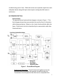
The parental device functional block diagram is shown in Figure 1. This
block diagram shows the communication links and the flow of information
within the parent device. Below is a list of each functional block within the
figure. Each block in the list is described by its communication with other
functional blocks.
Figure 1 – Parent Block Diagram
-
Antenna and Transceiver: These blocks work together to form the
communication link between the parental unit and the child unit.
Transmission from the parent to the child units is comprised of the
5
parent’s longitude and latitude coordinates. In response, the child unit
transmits panic information along with the distance and direction from
the parent.
-
UART: The information received from the child device and GPS
receiver travels along a serial link through the UART to form an eightbit bus. This data then travels into the first of three software
components within the PIC16F877.
-
Panic Button: This block represents a button that the parent can push
to engage or disengage the alarm mechanism. The panic request
travels into the software where the panic state is analyzed. The panic
state is then stored and transmitted along with the next poll-children
request.
-
Number of Children: This block is used for the parent to enter the
number of children at the start-up or to change the number of children
during operation of the parental device.
-
GPS receiver: This block receives a RF (radio frequency) signal, which
it analyzes in order to determine it's own location and the current time
of day. This data determined by the GPS unit will be sent serially
through the UART and stored by a software component.
-
Bus-Switch: This block will determine if the data entering the UART is
communicating with the transceiver or the GPS unit.
-
Coordinate Manipulation: This block will first check the child selector
switch to determine the number of children. This block will then start
polling the children through the transceiver. It will gather and store
both the parent and child GPS coordinates.
-
Panics or Alarms: This block will check the data received from the child
through the transceiver for the child's panic state. A child's panic state
is considered "on" under any of two conditions: if the child is out of
range of the parent and/or if the child has pressed their own panic
button.
-
Distance and Direction: This block takes the child information received
by the transceiver uses the digital compass to update the direction. It
then displays the child information on the display.
-
Display: This block contains a display for the parent, which shows the
distance and direction to the child(ren).
6
-
Audio Alarm: This block contains an alarm to notify the parent that a
child is in a panic state.
-
Parent Panic LED: This block contains an LED that will turn on when it
receives a signal from the PIC. The only time it will receive a signal
from the PIC is when the parent presses the panic button on the parent
device. It will only turn off when the panic button is pressed again.
-
Digital Compass: This block contains a compass, which will constantly
provide the direction the parent is facing. This information is passed
directly to the PIC16F877.
7
Child Device
The child unit is represented by the block diagram shown in Figure 2. This
diagram displays all major components and the flow of data through the
child device.
Figure 2 – Child Block Diagram
*All blocks except the software components have the same description as
given for the parent block diagram.
-
Calculate Distance and Direction and Update Panic Status: This block
first gathers the child's current GPS coordinates. Next, the block
calculates distance and direction relative to the parent’s location. It
gathers panic information from the latching panic button and delivers
this information to the UART for transmission to the parent.
8
-
Panic LED: This block checks the "panics or alarms" functional block
to see if any panics-requests have been sent. If, in fact, a panicrequest has been sent, the LED will turn on.
-
Out of Range LED: This block checks the out-of-range bit in the data
received from the parent. If the bit is set (value = 1), the LED will turn
on. The LED will only turn off when it is determined that the child is no
longer outside the range of the parent’s device.
SYSTEM COMPONENTS
This is a brief description of each device in the circuit schematics to follow. The
purpose of this section is not to explain in detail how each device interacts but
more as an introduction to the components in the following schematics and circuit
board layouts. A more detailed analysis will follow.
5 VOLT REGULATOR, 3 VOLT REGULATOR: These chips are used to
convert the ~ 9V DC voltage to appropriate voltage levels for our devices.
- The 5 Volt regulator is a 7805 chip and requires a minimum of 7.2 volts
to reliably output 5 volts.
- The 3 Volt regulator is an LM317T chip that reduces the voltage from
the batteries to 3 volts. This chip requires at least a 5.2 volt input to
reliably maintain a 3 volt output.
- The 3 and 5 volt power busses are located on the printed circuit board
of the parent and the perforated circuit board of the child.
PIC16F877: This is a MicroChip programmable IC that controls the inputs
and outputs from each device.
- The chip is equipped with multiple I/0 ports and one serial port used for
communicating between the GPS receiver and the transceiver.
- This device uses a 20 MHz crystal to set the clock speed of the device.
LX2400S-10A TRANSCEIVER: The transceiver is used as the
communication link between child and parent devices.
- The transceiver used in our devices is the Aerocomm AC1524C-10A
(LX2400S-10A).
- The transceiver is capable of communicating at speeds up to 115,200
bps, but both the parent and child devices are designed to
communicate at 9600 baud.
- The range of the transceivers are 3000 ft. outdoors and 300 ft. indoors.
- The transceivers need a voltage source of 5V ± 2%. This is one of the
main purposes of the voltage regulation circuit.
9
-
-
The transceivers typically sink 115mA (each) and have a typical output
power of 11mW.
The transceivers operate in the 2.402 - 2.478 GHz frequency band.
Transmission sequence to the transceivers must be in the following
format: 5555553A"length""data" where length is the 32-bit integer
representing the number of bytes of "data".
Information received from the transceivers is in the format
”length""data".
MOTOROLA ONCORE M12 GPS RECEIVER: The GPS receiver
receives information from GPS satellites to triangulate its longitude and
latitude coordinates.
- The receiver requires at least 2.8 – 3.2 volts to operate.
- Requests for position and position output from the receiver is sent
through a serial connection at 9600 baud in Motorola Binary format.
- Requests must be sent using 3 Volt logic.
- Transmission for the receiver use 3 Volt logic.
7404 NOT, 7408 AND, 7432 OR: These three TTL logic chips make up
the bus switch.
- The bus switch receives inputs from the PIC to switch serial
communication between the GPS receiver and transceiver.
LCD (Parent unit only):
- The LCD is used in our design for an output device to display location
information of each child.
- It receives its inputs from port B (pins 34 - 40) of the parent
PIC16F877. Pin 33 of port B on the parent PIC is not used for the
LCD.
- The LCD is initialized, programmed and controlled using a 4-bit data
bus instead of the 8-bit data bus that can alternately be used.
- The LCD is initialized after the voltage to the display has risen above
4.5V using software. The initialization takes place after the GPS’s
have been given their time to acquire coordinates. This initialization
sequence can be seen on the display by the screen turning blank.
- The programming for the LCD is done to store characters into the CG
RAM (Character Generated Random Access Memory) that we needed
to display that were not already programmed into the display.
- The controlling of the LCD is just basically putting everything that the
parent (distance and direction) has gathered from the child(ren) onto
the screen for the parent to use to track their child(ren).
DIGITAL COMPASS 1490(Parent only): The digital compass tells the
direction the parent is facing using a 4 bit output.
- The digital compass is made by Densmore and is capable of detecting
8 different directions.
10
-
-
The compass can accept input voltages from 5 – 12 volts. The design
specified in the following schematics use a 5 volt source.
The compass uses the magnetic field created by the earth to
determine position.
There is a transistor for each major direction (N,S,E,W). If the
compass is directed in one of the following directions, the appropriate
output pin sends a corresponding low voltage output.
The device is connected to port A of the parent device and has pull up
resistors to keep voltage levels at 5 volts.
1K resistors are used to limit the amount of current into the PIC16F877
and the compass.
11
Complete Circuit Schematics
Figure 3 – Parent Schematic
12
Figure 4 – Child Schematic
13
Circuit Board Layouts
Digital
Compass
5 Volt
Power Bus
LCD
Connector
Ground
Bus
3 Volt
Power Bus
GPS
Connector
Transceiver
Connector
PIC16F877
5 Volt
Power Bus
Child Selector
Switch
Figure 5 – Parent PCB Layout
14
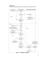
SOFTWARE DESCRIPTION
Parent Device
The flow chart below describes the software on the parent PIC16F877.
Each block will be broken down in the following explanation.
Figure 6 – Parent Flow Chart
15
Block 1: Getting ready for operation
-
The GPS requires up to 90 seconds to acquire enough satellites to
determine the parent device’s location.
The PIC16F877 checks to see how many children are present by
checking which dipswitches are moved to the on position.
Block 2: Getting ready for transmission to child device
-
-
-
The PIC16F877 checks to see if the parent alarm has been pressed
and stores the status of the alarm button
The PIC16F877 sends a request to the GPS for the current position of
the parent device. The longitude and latitude given by the GPS is then
stored. The GPS and PIC16F877communication can be watched by
monitoring the USART transmit pin (PIN 25), and the USART receive
pin (PIN 26) on the PIC16F877. Refer to Appendix A for the request
sent to the GPS and a typical response received from the GPS.
The PIC16F877 then checks PINS 2-5 (A0-A3) to get the current
heading of the parent from the digital compass. Appendix B shows
what the digital compass should output given its orientation.
The PIC16F877 then updates the LCD with the parent device’s relative
direction to the child devices.
The parent device is designed to update the direction to each child on
the LCD every 20 milliseconds. However every 10 seconds the child’s
distance from parent to child is updated, during this maneuver the
direction to each child isn’t updated until the parent device is finished
updating the LCD with the new distance. This operation takes less
than a second, but during this time the direction isn’t updated.
Block 3: Transmitting to child devices and receiving from child devices
- The longitude and latitude received from the parent GPS and the alarm
status are transmitted to the child device using the spread spectrum
transceiver. The PIC16F877 and transceiver communication can be
watched by monitoring the USART transmit pin (PIN____) on the
PIC16F877. Refer to Appendix C for a typical transmission sent to the
child device. (NOTE: A transmission may be repeated several times in
order to compensate for the frequency hopping of the transceivers, so
this may happen more than once.)
- After transmitting the information the parent device enters a receive
mode in which it waits to receive the distance and direction back from
the child device. The PIC16F877and the transceiver communication
can be watched by monitoring the USART receive pin (PIN 26) on the
PIC16F877. Refer to Appendix C for a typical transmission received
from the child device.
16
-
Block 3 can be repeated up to 4 times, depending on the number of
child devices present.
Block 4: Checking and storing information received from the child device
- Occasionally the child device may not respond. This either means
there is a problem with the child device, but more likely the child device
has gone beyond the 0.5 mile range of the parent device. If this even
occurs the parent device will assume the child is out of range.
- If the child device sends a transmission back to the parent device, the
transmission goes through a series of checks.
o Checks child device’s panic state.
o Checks child device’s distance from parent
Refer to Appendix C to see the transmission received from the child
and what is checked to know the state of the child.
Block 5: Updating LCD and alarms
- The parent device alarm is turned on if any child device is out of range,
or child device panic button has been pressed.
- The parent device LCD is updated with the child device’s new out of
range and panic information.
17
Child Device
The flow chart below describes the software on the child PIC16F877.
Figure 7 – Child Block Diagram
18
Block 1: Waiting for GPS acquisition and parent information
- The PIC16F877 waits 90 seconds for the GPS to acquires satellites
and determine the child device’s longitude and latitude coordinates.
The GPS and PIC16F877communication can be watched by
monitoring the USART transmit pin (PIN 25), and the USART receive
pin (PIN 26) on the PIC16F877. Refer to Appendix A for the request
sent to the GPS and a typical response received from the GPS.
- The PIC16F877 enters a receive mode, until it receives the parent
devices location and alarm status or times out. If the child devices
times out this means the parent device didn’t send a transmission.
The PIC16F877and the transceiver communication can be watched by
monitoring the USART receive pin (PIN 26) on the PIC16F877. Refer
to Appendix C for a typical transmission received from the child device.
Block 2: Process and store the information received from the parent
device
- The parent’s transmission to the child includes the child’s out of range
and the parent’s alarm information. According to the transmission
received by the child device the appropriate LED’s and the alarm is
turn on.
Block 3:
- Now that the parent location and the child location is known, the
distance and direction from parent to child is calculated for
transmission back to the parent device.
Block 4:
- Now that the distance and direction of from the parent is located, it is
transmitted back to the parent. The transceiver and PIC16F877
communication can be watched by monitoring the USART transmit pin
(PIN 25) on the PIC16F877. Refer to Appendix C for a typical
transmission received from the child device.
19
SUBSYSTEM BREAKDOWN
The Microchip processor is responsible for controlling each device. If the parent
or child device would fail to operate, the problem may be found by checking one
of the following subsystems. Below is a listed of expected outputs from each
device including possible reasons for error.
* The pinouts for many many of the devices are included in the text and in
appendices. It may be helpful in troubleshooting to download the specifications
for each device from the manufactures homepage.
Power Circuit
Refer to the schematic of the power circuit located in the schematics in
Figure 2 and Figure 3 on pages 11 and 12. The circuit can be found on
the perforated circuit board within the parent and child units. With fully
charged batteries there should, the power circuit should always output
4.85-5.15 volts and 2.85-3.15 to the respective power bus. To verify this,
check that there is 3 volts at the output of pin 3 of the 3V voltage regulator
and 5 volts at the output pin 3 of the 5V voltage regulator. If the
appropriate voltage levels are found, the regulators are working properly.
Also check the power busses located on the parent/child device to ensure
proper voltage readings. If an unexpected voltage level is found, check all
connections within the power circuit and the parent/child main circuit
board.
PIC16F877
As previously mentioned, the PIC16F877 controls all input and output
devices. A good indication that the PIC may be malfunctioning is if the
LCD never initializes. The fist place to check is the power circuit. Make
sure appropriate voltages are on the power busses. Next, check to see if
pin 1 and pin 11 have 5 volts. Next, check all grounds to the PIC. Refer
to the schematics to find which pins are tied to ground. Another possible
problem may be the oscillator. Using an oscilliscope, the oscillator can be
tested for the right frequency output. If all this seems to be operating
correctly, the PIC may need to be replaced. Replace the PIC with another
PIC with the same specifications and the respective .hex file generated
from MPLAB – C.
Transceiver
To ensure that the transceivers are communicating properly, first monitor
pin 20 of the transceiver in the child device. After startup, the pin should
at first be logic level high and after approximately 7-15 seconds the pin
should go low. If pin 20 never goes low, the transceivers may have been
switched, and the process should be repeated on the transceiver in the
parent device. If pin 20 of the transceiver in the parent device goes low,
20
switch the transceivers and the system should function properly. If neither
pin 20 of the transceiver in the parent device or the child device goes low,
then proceed with the following tests. First, check the amount of current
that the parent and child devices are sinking. Each device should sink
approximately 230mA. If either of the devices is sinking less than 230mA
of current, check continuity between the transceiver and the 5V bus. If
either of the devices is sinking considerably more than 230mA, the
transceiver is not functioning correctly and the manufacturer should be
contacted. If the devices are sinking the correct amount of current, the
EEPROM on one or both of the transceivers could be corrupted.
GPS
If the LCD starts initialization but returns a blank screen, then it is a good
indication the parent GPS is not responding.
It is more difficult to determine if the child GPS quits responding. If the
child GPS quits responding, the parent will “timeout” and an alarm will
sound. This will also happen if the transceiver quits working and if the
child device is not turned on. The best way is to test that the child device
is turned on and the child transceiver is functioning properly. Once this is
confirmed, step throught the following GPS checkpoints.
Appendix H has a complete list of GPS pinouts.
- Check the power buses for the appropriate busses. Refer to the power
circuit troubleshooting area if there are unexpected voltage levels.
- Check to see if the appropriate pins are receiving the specified voltage
levels.
- If so, it is now time to construct the RS232 circuit in Appendix D.
- Make sure the TTL output pin is stepped down from 5 volts to 3 volts
before connecting to the GPS RX pin.
- Connect the GPS TX pin to the TTL receive pin on the MAX232CPE
chip.
- Open a serial monitoring program on computer. Send the following
hex statement, 40407100340D0A, to the GPS and monitor the
response in ASCII. The response should follow the response in
Appendix A.
Refer to the Motorola webpage for the M12 GPS receiver if the problem
persists.
Compass
The digital compass is designed to use a 4 bit bus to determine the
direction the parent is facing. An indication that the compass has been
damaged or is not working correctly is if the parent device arrow is
changing but not pointing in the direction of the child. The compass can
be easily taken out of the circuit and tested. Appendix B has the pinouts
for the digital compass. Connect the ground and the power pins as
shown. Use resistors to limit the current under 20 mA to the digital
compass data pins (pin 3 on each side of the compass). Connect the
21
LEDs to a 5 Volt source and move the compass in all directions. The
LEDs will light up when they the data pin goes low and sinks the current.
If the devices fails to light LEDs or lights up the LEDs in a haphazard
manner, then the compass made need replacement.
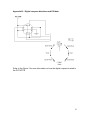
LCD
There are two possible problems that could occur with the LCD. The LCD
just may not turn on, or the LCD may be display unusual or foreign
characters to the screen. If one of these situations occurs, perform one of
the following tasks:
- If the LCD quits working there are two possible solutions that should be
tried.
- First, adjust the potentiometer located on the power circuit board. If
you still see nothing on the screen try the next step.
- Carefully remove the ribbon cable from the parent PCB board. Build a
test circuit as seen below in Figure 8. Adjust the potentiometer, and if
you still see nothing, the LCD is probably broken and will need to be
replaced. If you do see the black squares on the screen on lines 1 and
Figure 8 – LCD Potentiometer circuit
-
3 then the LCD is working properly and only the potentiometer will
need to be replaced. When inserting the LCD back onto the parent
PCB, be careful and makes sure that PIN 1 on the LCD is connected to
PIN 1 on the board. The brown wire on the ribbon cable and the
leftmost PIN on the board are PIN 1 on both the LCD and the board.
If the LCD just starts displaying some unusual or foreign characters to
the screen, the devices just simply need to be restarted. If the problem
continues make sure that the LCD is plugged tightly onto the parent
board and check the PIC16F877 troubleshooting section.
22
Bus Switch System
The only foreseen problem with the bus switch system is the failure of one
of the three logic chips used to form the switch or a broken connection. In
order to test this system, a Maxim232 RS232 chip and the serial port of a
computer with appropriate software must be used to probe the circuit.
First, connect the RS232 chip to a serial port of a computer and open any
software program that will allow the data to be viewed in hexadecimal
values. Next, place the probe on pin 25 of the PIC16F877 and turn on the
system. After 90 seconds, a request to the GPS receiver should appear
followed by a transmission to the transceiver. If both requests appear
repeatedly, then the bus switch is functioning correctly. If the requests
never appear, be sure that the correct pin is being probed. If the requests
appear only once, then the receive pins of both the transceiver and the
GPS receiver need to be probed (refer to Fig. ???? to locate the correct
pins). If the data is not being received by either or both of the devices,
then trace the continuity through the bus switch by using Fig. ????. If
there is no discontinuity, then test each chip for power and ground
(located on pins 7 and 14 of each logic chip). If all chips in the switch
have power and ground and there are no discontinuities, then one or more
of the chips must not be functioning correctly. Replace each chip noting
that the 7404 "NOT" chip needs to be replace by a chip that interfaces
with the GPS receiver's 3V logic levels.
23
Appendix A: Position request sent to GPS and corresponding response
GPS location request:
ASCII - @@EqmC<CR><LF>
GPS response:
ASCII - @@Eq,mm,dd,yy,hh,mm,ss,dd,mm.mmmm,n,ddd,mm.mmmm,w,
shhhh.h,sss.s,hh.h,m,t,dd.d,nn,rrrr,aa,CCC<CR><LF>
(The parent device is only concerned with the current longitude and latitude all
other information can be disregarded.)
Date
mm month 01..12
dd
day 01..31
yy
year 99..19
UTC Time
hh
hours
mm minutes
ss
seconds
00..23
00..59
00..60
Latitude
dd
degrees
mm.mmmm minutes
n
direction
00.99
00.59.9999
N=North, S=South
Longitude
ddd
mm.mmm
w
degrees
minutes
direction
000..180
00.59.9999
W=West, E=East
Velocity
sss.s
hhh.h
speed in knots
000.0..999.9
heading in degrees 000.0..359.9
Reciever status
m
fix mode
0 = autonomous
1 = differential
t
fix type
0 = no fix
1 = 2D fix
2 = 3d fix
3 = propagate mode
dd.d dilution of preciesion(DOP)
00.0..99.9
nn
number of satellites in use
00..37
rrrr
reference station ID
0000..1023
aa
age of differential data in s
00..60
CCC checksum
000..255
24
Appendix B – Digital compass directions and PIN data
Refer to the Figure 3 for more information on how the digital compass is wired to
the PIC16F778.
25
Appendix C: The transmission sent to the child device and transmission
received from child device.
Communication from Parent to Child Device(s)
byte 1
byte 2
8-bit Package ID
A
l
l
C
h
I
l
d
I
D
0
0
0
1
0
0
1
0
A
l
a
r
m
0
1
0
0
C
h
I
l
d
C
h
I
l
d
C
h
I
l
d
C
h
I
l
d
1
2
3
4
bytes 3 - 10
byte 11
Longitude and Latitude
8-bit Package ID
Out of Range
Child Alarm Control
C h I
L
C h I
L
C h I
L
C h I
L
d
d
d
d
1
2
3
4
Example: (Hexadecimal) 7300XXXXXXXXXXXXXXXXXX37 (X’s depend on
location)
Communication from Child Device(s) to Parent Device
byte 1
byte 2
X
X
byte 3 - 5
byte 6
distance and direction
8 bit package ID
X
8 bit package ID
C
h
I
l
d
P
a
n
i
c
C
h
I
l
d
4
C
H
I
L
D
3
C
h
I
l
d
2
C
h
I
l
d
1
2 byte
distance
1 byte
direction
Example: (Hexadecimal) 730145622137
26
Appendix D: Wiring Diagram for RS232 Communication
27
Appendix E: Complete Child Software
#device pic16f877
#include
#include
#include
#include
#include
<math.h>
<stdlib.h>
<16F877.H>
"trans.h"
"serial.h"
#define CHILD_NUMBER 1
#define pi 3.14159
#fuses HS,NOWDT,NOPROTECT
struct child_struct
{
float theta;
float latitude;
float longitude;
long int distance;
char direction;
}child;
struct parent_struct
{
float latitude;
float longitude;
}parent;
struct output_struct
{
char package_id;
char panic_and_child_id;
long int distance;
char direction;
//float theta;
char package_id_2;
}output;
struct input_struct
{
char package_id;
char panic_and_child_id;
float latitude;
float longitude;
char package_id_2;
}* input_packet;
void
void
void
void
get_cposition();
calc_distance(void);
calc_direction(void);
calc_theta(void);
28
float c_lat, c_lon;
main()
{
char
long
char
char
input_data[12];
int error,i;
*data;
data2[9];
output_low(PIN_B0);
delay_ms(20000);
delay_ms(20000);
delay_ms(20000);
delay_ms(20000);
delay_ms(20000);
delay_ms(20000);
delay_ms(20000);
delay_ms(20000);
delay_ms(19000);
//delay_ms(9000);
receive(input_data,12);
receive(input_data,12);
output.panic_and_child_id=0x00;
//output.distance=0;
//output.direction=0x00;
output_low(PIN_B0);
output_low(PIN_B1);
output_low(PIN_B3);
while(TRUE)
{
//output_low(PIN_B4);
//output_low(PIN_B5);
//for(i=0;i<10000;i++) //loop for ~10 seconds
//{
//
if(kbhit()==0)
//
{
//
delay_ms(1);
//
}
//
else
//
{
error=transceiver_receive(input_data,11);
input_packet=(struct input_struct *)input_data;
if(error==11 && input_packet->package_id==0x73 &&
input_packet->package_id_2==0x37)
{
if(bit_test(input_packet>panic_and_child_id,7)==0)
{
if(bit_test(input_packet>panic_and_child_id,6)==0)
{
if(bit_test(input_packet>panic_and_child_id,5)==0)
29
{
/* exit loop if polling this
child */
i=10000;
//break;
}
}
}
}
/* get panic button state --> updates panic LED */
if((input(PIN_B3)==1) || (bit_test(input_packet>panic_and_child_id,4)==1))
{
/* set panic bit */
bit_set(output.panic_and_child_id,7);
/* turn on panic LED */
output_high(PIN_B1);
/* turn on audio alarm */
output_high(PIN_B0);
}
else
{
/* set panic bit to 0 */
bit_clear(output.panic_and_child_id,7);
/* turn panic LED off */
output_low(PIN_B1);
/* turn off audio alarm */
output_low(PIN_B0);
//
//}
}
}
if(error==11 && input_packet->package_id==0x73 &&
input_packet->package_id_2==0x37 && (bit_test(input_packet>panic_and_child_id,7)==0) && (bit_test(input_packet>panic_and_child_id,6)==0) && (bit_test(input_packet>panic_and_child_id,5)==0))
{
/* wait 50ms x (child#-1) */
if(CHILD_NUMBER==1)
error=bit_test(input_packet>panic_and_child_id,3);
else if(CHILD_NUMBER==2)
error=bit_test(input_packet>panic_and_child_id,2);
else if(CHILD_NUMBER==3)
error=bit_test(input_packet>panic_and_child_id,1);
else if(CHILD_NUMBER==4)
error=bit_test(input_packet>panic_and_child_id,0);
30
if((error==1)/* || (input(PIN_B3)==1)*/)
{
/* turn on alarm */
output_high(PIN_B0);
/* turn on green gereral alarm LED */
output_high(PIN_B2);
}
else if(error==0)
{
/* turn off alarm */
output_low(PIN_B0);
/* turn green gereral alarm LED off */
output_low(PIN_B2);
}
/* get panic data */
error=bit_test(input_packet->panic_and_child_id,4);
if((error==1) || (input(PIN_B3)==1))
{
output_high(PIN_B0);
output_high(PIN_B1);
}
else
{
output_low(PIN_B0);
output_low(PIN_B1);
}
/* get location from GPS */
//Bus Switch code
//delay_ms(1000);
output_low(PIN_B4);
output_high(PIN_B5);
get_cposition();
/* is location valid */
/* if not valid current_loction=previous_location */
/* if valid save current_location */
/* get distance and direction */
//child.longitude = 39.6334;//~30ft
//child.latitude = 79.9639;
//parent.latitude = 39.6333;
//parent.longitude = 79.9639;
parent.latitude=input_packet->latitude;
parent.longitude=input_packet->longitude;
calc_distance();
calc_theta();
calc_direction();
/* get panic button state */
if(input(PIN_B3)==1)
31
{
/* set panic bit */
bit_set(output.panic_and_child_id,7);
/* turn on panic LED */
output_high(PIN_B1);
}
else
{
/* set panic bit to 0 */
bit_clear(output.panic_and_child_id,7);
/* turn panic LED off */
output_low(PIN_B1);
}
/* initialize output packet */
output.package_id=0x73;
output.package_id_2=0x37;
output.distance=child.distance;
output.direction=child.direction;
//output.theta=child.theta;
//output.distance=100;
//output.theta=99.99;
//output.direction=0x00;;
if(CHILD_NUMBER==1)
{
bit_clear(output.panic_and_child_id,5);
bit_clear(output.panic_and_child_id,6);
}
else if(CHILD_NUMBER==2)
{
bit_set(output.panic_and_child_id,5);
bit_clear(output.panic_and_child_id,6);
}
else if(CHILD_NUMBER==3)
{
bit_clear(output.panic_and_child_id,5);
bit_set(output.panic_and_child_id,6);
}
else if(CHILD_NUMBER==4)
{
bit_set(output.panic_and_child_id,5);
bit_set(output.panic_and_child_id,6);
}
/* transmit output packet */
//output.distance=100;
//output.direction='N';
output_low(PIN_B5);
output_high(PIN_B4);
data=&output;
transceiver_transmit(data,6);
}
else
{
32
/* turn on alarm */
output_high(PIN_B0);
/* turn on green out of range LED */
output_high(PIN_B2);
}
}
}
/**********************************************************************
***************************************************/
/****************************************/
/* transmits first n characters of the */
/* output array where n=length
*/
/****************************************/
void transmit(char output[20], int length)
{
int i=0;
for(i=0;i<length;i++)
{
putc(output[i]);
}
}
/***************************************/
/* receives n characters and stores
*/
/* them in the first n elements of the */
/* input array where n=length and is
*/
/* NOT equal to 0. If lenght=0, it
*/
/* continues to get characters data
*/
/* it receives a carriage return
*/
/***************************************/
int receive(char input[20], int length)
{
char data='a';
long int timeout=0;
int i=0;
int kbhit=0;
//timeout=0;
//if(length==0)
//{
// while(data != 0x0D)
// {
//
kbhit=kbhit();
//
//
//
//
//
//
/* wait max of 20 ms */
while((kbhit==0)&&(++timeout<2000))
{
delay_us(10);
kbhit=kbhit();
}
//
if(timeout>=2000)
33
//
//
//
//
//
//
//
//
//
//
//
//
//
//
//
return 0;
if(kbhit)
{
data=getc();
input[i] = data;
i++;
}
else
{
return i;
}
}
}
else
{
//
//
//
//
//
//
//
//
//
//
//
//
//
//
input[0]=0x00;
input[1]=0x0B;
input[2]=0x73;
input[3]=0x10;
input[4]=0x00;
input[5]=0x00;
input[6]=0x00;
input[7]=0x00;
input[8]=0x00;
input[9]=0x00;
input[10]=0x00;
input[11]=0x00;
input[12]=0x37;
return 13;
while(i<length)
{
timeout=0;
kbhit=kbhit();
/* wait max of 20 ms */
while((kbhit==0)&&(++timeout<2000))
{
delay_us(10);
kbhit=kbhit();
}
if(kbhit)
{
data=getc();
input[i] = data;
i++;
}
else
{
return i;
}
}
//
}
return i;
34
}
/**************************************************/
/*
*/
/* transceiver transmit
*/
/*
*/
/**************************************************/
void transceiver_transmit(char data[20], int length)
{
char output[20];
output[0]=PREAMBLE;
output[1]=PREAMBLE;
output[2]=PREAMBLE;
output[3]=SYNC;
output[4]=0x00;
output[5]=(char)length;
//BUS SWITCH CODE
output_high(PIN_B4);
output_low(PIN_B5);
//make sure the transceiver is not in hopping state
while(input(DSR)!=1)
{
delay_us(10);
}
output_low(TE);
while(input(CTS)!=0)
{
delay_ms(1);
}
transmit(output,6);
transmit(data,length);
output_high(TE);
while(input(CTS)!=1)
{
delay_us(10);
}
//if the transceiver has hopped while transmitting repeat
transmission
//if(input(DSR)==0)
//{
//clear latch
//transceiver_transmit(data,length);
//}
}
/**************************************************/
35
/*
*/
/* transceiver receive
*/
/*
*/
/**************************************************/
int transceiver_receive(char data[20],int length)
{
long int len,i;
char receive_data[20];
//BUS SWITCH CODE
/* receive length+2 bytes -> accounts for lenght high and low
bytes from transceiver */
for(i=0;i<10000;i++)
{
if(kbhit() == 1)
{
break;
}
delay_ms(1);
}
if(i<10000)
{
len=receive(receive_data,length+2);
/* strip the length_high and length_low bytes off of transmission
*/
for(i=0;i<len-2;i++)
{
data[i]=receive_data[i+2];
}
return (int)receive_data[1];
}
else
{
return 0;
}
}
/**************************************************/
/*
*/
/* get position
*/
/*
*/
/**************************************************/
void get_cposition()
{
char output[8];
char input[27];
36
char crap;
long int i=0;
int data_length=0;
float temp;
float latitude = 2.55;
float longitude = 6.66;
//delay_ms(2000);
output[0]=0x40; //
output[1]=0x40; //
output[2]=0x45; //
output[3]=0x71; //
output[4]=0x00; //
output[5]=0x34; //
output[6]=0x0D; //
output[7]=0x0A; //
@
@
E
q
0 for the mode of output(once)
Checksum for (Eq0)
Carriage Return
Line Feed
data_length=receive(input,27);
transmit(output,8);
while(kbhit()==0)
{
delay_us(10);
}
data_length=receive(input,23);
data_length=receive(input,27);
/* Conversion of the input[0-9] into floating point latitude
*/
latitude = (((int)input[0]-48)*10) + ((int)input[1]-48);
temp = ((((int)input[3]-48) * 10) + ((int)input[4]-48));
temp = temp + ((((int)input[6]-48)*.1) +(((int)input[7]-48)*.01));
temp = temp + ((((int)input[8]-48)*.001) + (((int)input[9]48)*.0001));
temp = temp/60;
latitude = latitude + temp;
child.latitude = latitude;
/* Conversion of the input[13-26] into floating point longitude
*/
longitude = (((int)input[13]-48)*100);
longitude = longitude + (((int)input[14]-48)*10) + ((int)input[15]48);
temp = ((((int)input[17]-48) * 10) + ((int)input[18]-48));
temp = temp + ((((int)input[20]-48)/10) +(((int)input[21]-48)/100));
temp = temp + ((((int)input[22]-48)/1000) + (((int)input[23]48)/10000));
temp = temp/60;
longitude = longitude + temp;
child.longitude = longitude;
if ((longitude == 0) && (latitude ==0))
{
output_high(PIN_B2);
}
data_length=receive(input,26);
37
data_length=receive(input,23);
}
/******************************************/
/* temp distance and direction
*/
/******************************************/
void calc_theta()
{
float c_lat, c_lon;
float int_c_lon, int_c_lat;
c_lat = child.latitude - parent.latitude;
c_lon = child.longitude - parent.longitude;
//int_c_lon=(long int)ceil(c_lon);
//int_c_lat=(long int)ceil(c_lat);
int_c_lon = c_lon;
int_c_lat = c_lat;
if(int_c_lat == 0.0 && int_c_lon == 0.0)
child.theta = 90.0;
else if(int_c_lat == 0.0 && int_c_lon < 0.0)
child.theta = 0.0;
else if(int_c_lat == 0.0 && int_c_lon > 0.0)
child.theta = 180.0;
else if(int_c_lon == 0.0 && int_c_lat < 0.0)
child.theta = 270.0;
else if(int_c_lon == 0.0 && int_c_lat > 0.0)
child.theta = 90.0;
else
{
child.theta = atan(c_lat / c_lon);
child.theta = child.theta*180.0/3.1415926535898;
if(int_c_lat > 0.0 && int_c_lon < 0.0)
child.theta = -(child.theta);
else if(int_c_lat < 0.0 && int_c_lon > 0.0)
child.theta = 180.0 - child.theta;
else if(int_c_lat < 0.0 && int_c_lon < 0.0)
child.theta = 360.0 - child.theta;
else
child.theta = 180.0 - child.theta;
}
}
void calc_direction(void)
{
if((child.theta > 337.5 && child.theta <= 360.0) || (child.theta
>=0 && child.theta <= 22.5))
child.direction = 'E';
else if(child.theta > 22.5 && child.theta <= 67.5)
child.direction = 'P';
else if(child.theta > 67.5 && child.theta <= 112.5)
38
child.direction
else if(child.theta >
child.direction
else if(child.theta >
child.direction
else if(child.theta >
child.direction
else if(child.theta >
child.direction
else
child.direction
= 'N';
112.5 &&
= 'Q';
157.5 &&
= 'W';
202.5 &&
= 'Z';
247.5 &&
= 'S';
child.theta <= 157.5)
child.theta <= 202.5)
child.theta <= 247.5)
child.theta <= 292.5)
= 'M';
}
void calc_distance(void)
{
float lat_sqr, lon_sqr, dist;
lat_sqr = (69.1*69.1*(child.latitude-parent.latitude)*(child.latitudeparent.latitude));
lon_sqr = (53*53);
lon_sqr *= (child.longitude-parent.longitude)*(child.longitudeparent.longitude);
dist = sqrt(lat_sqr + lon_sqr);//in miles
dist *= 5280.0;//in feet
child.distance = (long int)dist;
}
//void calc_distance(void)
//{
/**********************************************************************
**/
/*
Approximate distance in miles = sqrt(x * x + y * y)
*/
/*
*/
/*
where x = 69.1 * (lat2 - lat1)
*/
/*
and y = 53 * (lon2 - lon1)
*/
/*
*/
/*
You can improve the accuracy of this approximate distance
*/
/*
calculation by adding the cosine math function:
*/
/*
*/
/*
Approximate distance in miles = sqrt(x * x + y * y)
*/
39
/*
*/
where x = 69.1 * (lat2 - lat1)
*/
/*
and y = 69.1 * (lon2 - lon1) * cos(lat1/57.3)
*/
/**********************************************************************
**/
/*
/*
float lat_sqr, lon_sqr, dist, more_accurate_calc;
lat_sqr = (69.1*69.1*(child.latitudeparent.latitude)*(child.latitude-parent.latitude));
more_accurate_calc = cos((parent.latitude)/57.3);//only used for
more accurate calculation, can be taken out (cont.)
lon_sqr = (69.1*69.1);
lon_sqr *= more_accurate_calc * more_accurate_calc;//this line
can be taken out if not enough RAM (concluded)
lon_sqr *= (child.longitude-parent.longitude)*(child.longitudeparent.longitude);
dist = sqrt(lat_sqr + lon_sqr);//in miles
dist *= 5280.0;//in feet
child.distance = (long int)dist;
}*/
40
Appendix F: Complete Parent Software
/* Parent Device Software */
/* Created by Team 20 Child Locator */
#device PIC16F877
#include <16F877.H>
#include "trans.h"
#include "serial.h"
#include "display.h"
#use fast_io(B)
//Decreases the number of lines in the output of Port
B
#include<stdlib.h>
#include<math.h>
#fuses HS,NOWDT,NOPROTECT
/* Declaring global variables */
struct child_struct
/* Global structure for storing child
information */
{
boolean present; /* Tells parent device if child is present
(switch info) */
long int distance;
/* Distance from parent to child */
char direction;
/* Relative direction from parent to
child */
boolean oor;
/* Set if child[i] is out of range */
boolean panic;
/* Set if child[i] sends a panic */
} child[4];
struct parent_struct
information */
{
boolean panic;
char direction;
}parent;
/* Global structure for storing parent
/* Child Panic state */
/* N S E W Q Z M P */
struct output_struct
{
char package_id; /* Package id for transmission */
char alarm_id;
/* Store parents alarm button
status */
float latitude;
/* Latitude of the parent */
float longitude; /* Longitude of parent */
char package_id_2;
/* Ending package id for
transmission */
}to_child;
/* Start of main program */
main()
{
struct input_struct
recieved data from child */
{
/* Structure for
41
char package_id;
transmission */
char panic_and_child_id;
information */
long int distance;
to parent */
char direction;
from parent to child */
char package_id_2;
for transmission */
}*from_child;
/* Package id for
/* Child id and panic
char input[7];
from child */
char *output;
child */
int i, j;
code */
boolean transmit_time = false;
transmit request to child */
boolean first_time = true;
through the code*/
int error;
checking errors on transmissions */
int time;
from GPS */
/* Distance from child
/* Relative direction
/* Ending package id
/* Message recieved
/* Message sent to
/* For loops in
/* Indicates time to
/* Is it the first time
/* Used for
/* Time recieved
/* Used to control bus switch, these are set so the bus switch
isn't floating
and the PIC doesn't recieve garbage */
output_low(PIN_C4);
output_low(PIN_C5);
/* Delay to let GPS acquire satellites */
delay_ms(20000);
delay_ms(20000);
delay_ms(20000);
delay_ms(20000);
delay_ms(20000);
delay_ms(20000);
delay_ms(20000);
delay_ms(20000);
delay_ms(20000);
/* Making sure USART buffer is empty */
error=receive(input,7);
error=receive(input,7);
error=receive(input,7);
error=receive(input,7);
error=receive(input,7);
/* LCD initilization */
set_tris_b(0x00); //sets port B to always output
initialize_lcd(); //initializes the LCD
42
create_arrows();
already on the LCD
display_on();
display characters
//creates the arrows for the direction not
//Turn the LCD on and makes it ready to
/* Set child1..4 out of range to false to begin with */
child[1].oor = false;
child[2].oor = false;
child[3].oor = false;
child[4].oor = false;
/* Inital location, in case parent doesn't get coordinates */
to_child.latitude = 0.0;
to_child.longitude = 0.0;
/* Testing purposes*/
parent.direction = 'N';
output_low(PIN_C1);
/* Check external switches to see which children are present */
if (input(PIN_D0))
child[1].present = true;
else
child[1].present = false;
if (input(PIN_D1))
child[2].present = true;
else
child[2].present = false;
if (input(PIN_D2))
child[3].present = true;
else
child[3].present = false;
if (input(PIN_D3))
child[4].present = true;
else
child[4].present = false;
/* Main loop of execution*/
while(true)
{
/* Check if parent panic button is pressed */
if (input(PIN_E0)==1)
{
parent.panic = true;
output_high(PIN_A5);
}
else
{
parent.panic = false;
output_low(PIN_A5);
}
/* Check if time to request child location */
time = 0;
while (!transmit_time)
{
43
delay_ms(200);
if (time == 10)
{
transmit_time = true;
}
if(!first_time)
{
/* Uncomment get_compass if you want to use
compass, compass is useless if the
antenna is magnetic */
//get_compass();
/*function to get
compass info */
update_direction();
//updates the current
relative direction from
}
time++;
}
first_time = false;
transmit_time = false;
/* Get position from GPS */
output_high(PIN_C4);
output_low(PIN_C5);
get_position();
/* Get panic information ready to transmit to child devices
*/
to_child.alarm_id= 0x00;
//Cleared so alarm
information can be set below
for (i = 1; i<2; i++)
{
if(child[i].present==true)
{
/* Set child ID and alarm information */
if (i==1)
{
if (child[i].oor == true)
bit_set(to_child.alarm_id,3);
if (parent.panic == true)
bit_set(to_child.alarm_id,4);
}
if ((i==2) || (i==3) || (i==4))
{
bit_set(to_child.alarm_id,(3+i));
if (child[i].oor == true)
bit_set(to_child.alarm_id,(4-i));
if (parent.panic == true)
bit_set(to_child.alarm_id,4);
}
/* Get ready to transmit */
to_child.package_id = 0x73;
to_child.package_id_2 = 0x37;
to_child.alarm_id = 0x00;
output=&to_child;
44
/* Get bus switch ready */
output_low(PIN_C4);
output_high(PIN_C5);
transceiver_transmit(output,11);
/* Recieve from child device */
error=transceiver_receive(input,6);
from_child=(struct input_struct *)input;
/* Recieve child i information if not recieved
before, this takes care of
frequency hopping of transciever. Request
is sent until child recieves the
request*/
for (j = 1; j<10; j++)
{
if(error==0)
{
delay_ms(10);
output_low(PIN_C4);
output_high(PIN_C5);
transceiver_transmit(output,11);
error=transceiver_receive(input,6);
from_child=(struct input_struct
*)input;
}
/* If parent recieved a valid tranmission
before time expires break loop */
if(error==6 && from_child>package_id==0x73 && from_child->package_id_2==0x37)
{
if (from_child->distance == 0)
{
output_high(PIN_C1);
}
child[i].distance= from_child>distance;
child[i].direction = from_child>direction;
j = 10;
break;
}
}
/* Checks to see if child responded */
if(j >= 9)
{
child[i].oor = true;
}
/* If child responded check panic state of
child */
if(bit_test(from_child>panic_and_child_id,7)==1)
{
child[i].panic = true;
}
45
else
{
child[i].panic = false;
}
/* Determine if child is approaching range
limits */
if (child[i].distance > 2500)
child[i].oor = true;
else
child[i].oor = false;
}
}
/* Turn on parent alarm if any child devices are out of
2500 feet range */
if((child[1].oor || child[2].oor || child[3].oor) == true)
output_high(PIN_A5);
else
output_low(PIN_A5);
/* Update LCD with each child's position and info */
//Check Panic and OOR
check_pan_oor();
delay_ms(1000);
//Display child names
big_c();
low_h();
low_i();
low_l();
low_d();
one();
space();
//Display the distance
display_distance();
low_f();
low_t();
//Display the directions
//get_compass();
display_direction();
//Displays the rest of the children on the Display
display_roc();
}
}
/**********************************************************************
***************************************************/
/************************/
/* Get lon and lat */
/************************/
void get_position()
{
char output[8];
46
char input[27];
char crap;
long int i;
int data_length=0;
float temp;
float latitude;
float longitude;
//delay_ms(2000);
output[0]=0x40; //
output[1]=0x40; //
output[2]=0x45; //
output[3]=0x71; //
output[4]=0x00; //
output[5]=0x34; //
output[6]=0x0D; //
output[7]=0x0A; //
@
@
E
q
0 for the mode of output(once)
Checksum for (Eq0)
Carriage Return
Line Feed
data_length=receive(input,27);
transmit(output,8);
while(kbhit()==0)
{
delay_us(10);
}
data_length=receive(input,23);
data_length=receive(input,27);
/* Conversion of the input[0-9] into floating point latitude
*/
latitude = (((int)input[0]-48)*10) + ((int)input[1]-48);
temp = ((((int)input[3]-48) * 10) + ((int)input[4]-48));
temp = temp + ((((int)input[6]-48)*.1) +(((int)input[7]-48)*.01));
temp = temp + ((((int)input[8]-48)*.001) + (((int)input[9]48)*.0001));
temp = temp/60;
latitude = latitude + temp;
if (latitude != 0.0)
{
to_child.latitude = latitude;
}
/* Conversion of the input[13-26] into floating point longitude
*/
longitude = (((int)input[13]-48)*100);
longitude = longitude + (((int)input[14]-48)*10) + ((int)input[15]48);
temp = ((((int)input[17]-48) * 10) + ((int)input[18]-48));
temp = temp + ((((int)input[20]-48)/10) +(((int)input[21]-48)/100));
temp = temp + ((((int)input[22]-48)/1000) + (((int)input[23]48)/10000));
temp = temp/60;
longitude = longitude + temp;
if (longitude != 0.0)
47
{
to_child.longitude = longitude;
}
data_length=receive(input,23);
data_length=receive(input,26);
}
/****************************************/
/* gets time from GPS
*/
/* outputs seconds as integer
*/
/****************************************/
int get_time()
{
char output[8];
char input[22];
int data_length=0;
int time = 0;
output[0]=0x40;
output[1]=0x40;
output[2]=0x45;
output[3]=0x71;
output[4]=0x00;
output[5]=0x34;
output[6]=0x0D;
output[7]=0x0A;
//
//
//
//
//
//
//
//
@
@
E
q
0 for the mode of output(once)
Checksum for (Eq0)
Carriage Return
Line Feed
transmit(output,8);
data_length=receive(input,22);
/* Conversion of the input[20-21] into integer seconds
*/
time = (((int)input[20]-48)*10) + ((int)input[21]-48);
return time;
}
/****************************************/
/* transmits first n characters of the */
/* output array where n=length
*/
/****************************************/
void transmit(char output[20], int length)
{
int i=0;
for(i=0;i<length;i++)
{
putc(output[i]);
}
}
/***************************************/
/* receives n characters and stores
*/
/* them in the first n elements of the */
48
/* input array where n=length and is
*/
/* NOT equal to 0. If lenght=0, it
*/
/* continues to get characters data
*/
/* it receives a carriage return
*/
/***************************************/
int receive(char input[20], int length)
{
char data='a';
long int timeout=0;
int i=0;
int kbhit=0;
//timeout=0;
//if(length==0)
//{
// while(data != 0x0D)
// {
//
kbhit=kbhit();
//
//
//
//
//
//
/* wait max of 20 ms */
while((kbhit==0)&&(++timeout<2000))
{
delay_us(10);
kbhit=kbhit();
}
//
//
if(timeout>=2000)
return 0;
//
//
//
//
//
//
//
//
//
//
//
//
//
//
if(kbhit)
{
data=getc();
input[i] = data;
i++;
}
else
//
//
//
//
//
//
//
//
//
//
//
//
//
{
return i;
}
}
}
else
{
input[0]=0x00;
input[1]=0x0B;
input[2]=0x73;
input[3]=0x10;
input[4]=0x00;
input[5]=0x00;
input[6]=0x00;
input[7]=0x00;
input[8]=0x00;
input[9]=0x00;
input[10]=0x00;
input[11]=0x00;
input[12]=0x37;
49
//
return 13;
while(i<length)
{
timeout=0;
kbhit=kbhit();
/* wait max of 20 ms */
while((kbhit==0)&&(++timeout<2000))
{
delay_us(10);
kbhit=kbhit();
}
if(kbhit)
{
data=getc();
input[i] = data;
i++;
}
else
{
return i;
}
}
//
}
return i;
}
/**************************************************/
/*
*/
/* transceiver transmit
*/
/*
*/
/**************************************************/
void transceiver_transmit(char data[20], int length)
{
char output[20];
output[0]=PREAMBLE;
output[1]=PREAMBLE;
output[2]=PREAMBLE;
output[3]=SYNC;
output[4]=0x00;
output[5]=(char)length;
//BUS SWITCH CODE
//make sure the transceiver is not in hopping state
while(input(DSR)!=1)
{
delay_us(10);
}
output_low(TE);
while(input(CTS)!=0)
{
delay_ms(1);
}
50
transmit(output,6);
transmit(data,length);
output_high(TE);
while(input(CTS)!=1)
{
delay_us(10);
}
//if the transceiver has hopped while transmitting repeat
transmission
if(input(DSR)==0)
{
//clear latch
//transceiver_transmit(data,length);
}
}
/**************************************************/
/*
*/
/* transceiver receive
*/
/*
*/
/**************************************************/
int transceiver_receive(char data[20],int length)
{
long int len,i=0;
char receive_data[20];
//BUS SWITCH CODE
/* receive length+2 bytes -> accounts for lenght high and low
bytes from transceiver */
for(i=0;i<8000;i++)
{
if(kbhit() == 1)
{
break;
}
delay_ms(1);
}
if(i<8000)
{
len=receive(receive_data,length+2);
/* strip the length_high and length_low bytes off of transmission
*/
for(i=0;i<len-2;i++)
{
data[i]=receive_data[i+2];
51
}
return (int)receive_data[1];
}
else
{
return 0;
}
}
/****************************************************/
/*
*/
/*
displays the information about the rest of the */
/*
children
*/
/*
*/
/****************************************************/
void display_roc(void)
{
block();
block();
big_c();
low_h();
low_i();
low_l();
low_d();
three();
space();
pound();
pound();
pound();
pound();
low_f();
low_t();
block();
line2();
block();
block();
big_c();
low_h();
low_i();
low_l();
low_d();
two();
space();
pound();
pound();
pound();
pound();
low_f();
low_t();
block();
52
block();
block();
big_c();
low_h();
low_i();
low_l();
low_d();
four();
space();
pound();
pound();
pound();
pound();
low_f();
low_t();
block();
}
/****************************************************/
/*
*/
/*
updates the direction of the children
/*
*/
/****************************************************/
void update_direction(void)
{
int i;
*/
line1();
//calls line 1 on the LCD
for(i=0;i<15;i++)
cursor_move_right();//moves the cursor on the LCD 16 spaces
to the right
display_direction();
//calculates and displays the updated
direction
}
/****************************************************/
/*
*/
/*
displays the direction about all of the
*/
/*
children
*/
/*
*/
/****************************************************/
void display_direction(void)
{
long int pdir, cdir;
char pcdir, ccdir;
pcdir = parent.direction;
ccdir = child[1].direction;
pdir = get_dir(pcdir);
cdir = get_dir(ccdir);
53
pdir = pdir - cdir;
if(pdir == 0 || pdir == 360 || pdir == -360)
up_arrow();
else if(pdir == 45 || pdir == -315 || pdir == 405)
top_right_arrow();
else if(pdir == 90 || pdir == 450 || pdir == -270)
right_arrow();
else if(pdir == 135 || pdir == 495 || pdir == -225)
bottom_right_arrow();
else if(pdir == 180 || pdir == 540 || pdir == -180)
down_arrow();
else if(pdir == 225 || pdir == 585 || pdir == -135)
bottom_left_arrow();
else if(pdir == 270 || pdir == 630 || pdir == -90)
left_arrow();
else
top_left_arrow();
}
/****************************************************/
/*
*/
/*
gets a numerical representation of the character*/
/*
direction for the children
/*
*/
/****************************************************/
long int get_dir(char dir)
{
long int d;
switch(dir)
{
case 'N':
d = 90;
break;
case 'Q':
d = 135;
break;
case 'W':
d = 180;
break;
case 'Z':
d = 225;
break;
case 'S':
d = 270;
break;
case 'M':
d = 315;
break;
case 'E':
d = 0;
break;
default:
d = 45;
break;
}
*/
54
return d;
}
/****************************************************/
/*
*/
/*
displays the distance for the children
*/
/*
*/
/****************************************************/
void display_distance(void)
{
long int mult, ch_distance;
short int num = 0;
ch_distance = child[1].distance;
if(child[1].distance <= 9999)
{
mult = ch_distance;
mult = mult / 1000;
if(mult >= 1)
{
display_num(mult);
ch_distance = ch_distance - (mult * 1000);
num = 1;
}
else if(mult == 0)
{
space();
}
mult = ch_distance;
mult = mult / 100;
if(mult >= 1)
{
display_num(mult);
ch_distance = ch_distance - (mult * 100);
num = 1;
}
else if(mult == 0)
{
if(num == 0)
space();
else
zero();
}
mult = ch_distance;
mult = mult / 10;
if(mult >= 1)
{
display_num(mult);
ch_distance = ch_distance - (mult * 10);
num = 1;
}
else if(mult == 0)
{
if(num == 0)
space();
else
zero();
55
}
mult = ch_distance;
if(mult >= 1)
{
display_num(mult);
}
else if(floor(mult) == 0)
zero();
}
else
{
pound();
pound();
pound();
pound();
}
}
/****************************************************/
/*
*/
/*
function called from display_distance() to
/*
display the number characters to the LCD
*/
/*
*/
/****************************************************/
void display_num(int mult)
{
int i;
switch(mult)
{
case 1:
one();
break;
case 2:
two();
break;
case 3:
three();
break;
case 4:
four();
break;
case 5:
five();
break;
case 6:
six();
break;
case 7:
seven();
break;
case 8:
eight();
break;
case 9:
nine();
break;
*/
56
default:
zero();
break;
}
}
/****************************************************/
/*
*/
/*
displays to the LCD whether or not the panic
*/
/*
or out of range are set for a child
*/
/*
*/
/****************************************************/
void check_pan_oor(void)
{
if(child[1].present == true)
{
line1();
if(child[1].panic == true)
block();
else
space();
if(child[1].oor == true)
block();
else
space();
}
else
{
space();
space();
}
}
/****************************************************/
/*
*/
/*
initialized the LCD
*/
/*
*/
/****************************************************/
void initialize_lcd(void)
{
delay_ms(100);
//Wait more than 15ms after Vcc =
4.5V
// the number was made to be
100ms because
// of the wider voltage
operating range of
// the PIC compared to that
of the LCD
output_low(PIN_B1);
delay_ms(1);
57
output_low(PIN_B2);
//Function set: Sets interface to
4-bit
output_low(PIN_B3);
output_low(PIN_B4);
output_high(PIN_B5);
output_low(PIN_B6);
output_low(PIN_B7);
//0010
enable_hl();
//output_low(PIN_B2);
Set N and F
//output_low(PIN_B3);
character font)
output_low(PIN_B4);
output_high(PIN_B5);
output_low(PIN_B6);
output_low(PIN_B7);
//Function set: (Interface = 4-bit,
// for number of lines and
//0010
enable_hl();
//output_low(PIN_B2);
//output_low(PIN_B3);
output_low(PIN_B4);
output_low(PIN_B5);
output_low(PIN_B6);
output_high(PIN_B7);
//1000
enable_hl();
//output_low(PIN_B2);
//output_low(PIN_B3);
output_low(PIN_B4);
output_low(PIN_B5);
output_low(PIN_B6);
output_low(PIN_B7);
//Display ON
//0000
enable_hl();
//output_low(PIN_B2);
//output_low(PIN_B3);
output_low(PIN_B4);
output_high(PIN_B5);
output_high(PIN_B6);
output_high(PIN_B7);
//1110
enable_hl();
//output_low(PIN_B2);
//output_low(PIN_B3);
output_low(PIN_B4);
output_low(PIN_B5);
output_low(PIN_B6);
output_low(PIN_B7);
//Entry Mode Set:
//0000
enable_hl();
58
//output_low(PIN_B2);
//output_low(PIN_B3);
output_low(PIN_B4);
output_high(PIN_B5);
output_high(PIN_B6);
output_low(PIN_B7);
//0110
enable_hl();
}
//LINES OF DISPLAY
void line1(void)
{
//line one and three
output_low(PIN_B2);//rs low
output_low(PIN_B3);
output_low(PIN_B4);//1000
output_low(PIN_B5);
output_low(PIN_B6);
output_high(PIN_B7);
enable_hl();
//output_low(PIN_B2);
//output_low(PIN_B3);
output_low(PIN_B4);//0000
output_low(PIN_B5);
output_low(PIN_B6);
output_low(PIN_B7);
enable_hl();
}
void line2(void)
{
//line two and four
output_low(PIN_B2);//rs low
output_low(PIN_B3);
output_low(PIN_B4);//1100
output_low(PIN_B5);
output_high(PIN_B6);
output_high(PIN_B7);
enable_hl();
output_low(PIN_B4);//0000
output_low(PIN_B5);
output_low(PIN_B6);
output_low(PIN_B7);
enable_hl();
}
void cursor_move_left(void)
59
{
output_low(PIN_B2);//RS LOW
output_low(PIN_B3);//R/W LOW
output_high(PIN_B4);//0001
output_low(PIN_B5);
output_low(PIN_B6);
output_low(PIN_B7);
enable_hl();
output_low(PIN_B4);//0000
output_low(PIN_B5);
output_low(PIN_B6);
output_low(PIN_B7);
enable_hl();
}
void cursor_move_right(void)
{
output_low(PIN_B2);//RS LOW
output_low(PIN_B3);//R/W LOW
output_high(PIN_B4);//0001
output_low(PIN_B5);
output_low(PIN_B6);
output_low(PIN_B7);
enable_hl();
output_low(PIN_B4);//0100
output_low(PIN_B5);
output_high(PIN_B6);
output_low(PIN_B7);
enable_hl();
}
//DECIMAL
void decimal(void)
{
output_high(PIN_B2);
output_low(PIN_B3);
output_low(PIN_B4);
output_high(PIN_B5);
output_low(PIN_B6);
output_low(PIN_B7);
//RS TO HIGH
//R/W TO HIGH
//->0010 HIGH ORDER NIBBLE
enable_hl();
//output_high(PIN_B2);
//output_low(PIN_B3);
//RS TO HIGH
//R/W TO LOW
output_low(PIN_B4);
//->1110 LOW ORDER NIBBLE
60
output_high(PIN_B5);
output_high(PIN_B6);
output_high(PIN_B7);
enable_hl();
}
//NUMBERS
//zero
void zero(void)
{
//output_low(PIN_B1);
output_high(PIN_B2);
output_low(PIN_B3);
output_high(PIN_B4);
output_high(PIN_B5);
output_low(PIN_B6);
output_low(PIN_B7);
//E LOW
//RS TO HIGH
//R/W TO HIGH
//->0011 HIGH ORDER NIBBLE
enable_hl();
//output_high(PIN_B2);
//output_low(PIN_B3);
output_low(PIN_B4);
output_low(PIN_B5);
output_low(PIN_B6);
output_low(PIN_B7);
//RS TO HIGH
//R/W TO LOW
//->0000 LOW ORDER NIBBLE
enable_hl();
}
//one
void one(void)
{
//output_low(PIN_B1);
output_high(PIN_B2);
output_low(PIN_B3);
output_high(PIN_B4);
output_high(PIN_B5);
output_low(PIN_B6);
output_low(PIN_B7);
//E LOW
//RS TO HIGH
//R/W TO HIGH
//->0011 HIGH ORDER NIBBLE
enable_hl();
//output_high(PIN_B2);
//output_low(PIN_B3);
//RS TO HIGH
//R/W TO LOW
output_high(PIN_B4);
output_low(PIN_B5);
output_low(PIN_B6);
output_low(PIN_B7);
//->0001 LOW ORDER NIBBLE
enable_hl();
}
61
//two
void two(void)
{
output_high(PIN_B2);
output_low(PIN_B3);
output_high(PIN_B4);
output_high(PIN_B5);
output_low(PIN_B6);
output_low(PIN_B7);
//RS TO HIGH
//R/W TO HIGH
//->0011 HIGH ORDER NIBBLE
enable_hl();
//output_high(PIN_B2);
//output_low(PIN_B3);
output_low(PIN_B4);
output_high(PIN_B5);
output_low(PIN_B6);
output_low(PIN_B7);
//RS TO HIGH
//R/W TO LOW
//->0010 LOW ORDER NIBBLE
enable_hl();
}
//three
void three(void)
{
output_high(PIN_B2);
output_low(PIN_B3);
output_high(PIN_B4);
output_high(PIN_B5);
output_low(PIN_B6);
output_low(PIN_B7);
//RS TO HIGH
//R/W TO HIGH
//->0011 HIGH ORDER NIBBLE
enable_hl();
//output_high(PIN_B2);
//output_low(PIN_B3);
//RS TO HIGH
//R/W TO LOW
output_high(PIN_B4);
output_high(PIN_B5);
output_low(PIN_B6);
output_low(PIN_B7);
//->0011 LOW ORDER NIBBLE
enable_hl();
}
//four
void four(void)
{
output_high(PIN_B2);
output_low(PIN_B3);
output_high(PIN_B4);
output_high(PIN_B5);
//RS TO HIGH
//R/W TO HIGH
//->0011 HIGH ORDER NIBBLE
62
output_low(PIN_B6);
output_low(PIN_B7);
enable_hl();
//output_high(PIN_B2);
//output_low(PIN_B3);
output_low(PIN_B4);
output_low(PIN_B5);
output_high(PIN_B6);
output_low(PIN_B7);
//RS TO HIGH
//R/W TO LOW
//->0100 LOW ORDER NIBBLE
enable_hl();
}
//five
void five(void)
{
output_high(PIN_B2);
output_low(PIN_B3);
output_high(PIN_B4);
output_high(PIN_B5);
output_low(PIN_B6);
output_low(PIN_B7);
//RS TO HIGH
//R/W TO HIGH
//->0011 HIGH ORDER NIBBLE
enable_hl();
//output_high(PIN_B2);
//output_low(PIN_B3);
//RS TO HIGH
//R/W TO LOW
output_high(PIN_B4);
output_low(PIN_B5);
output_high(PIN_B6);
output_low(PIN_B7);
//->0101 LOW ORDER NIBBLE
enable_hl();
}
//six
void six(void)
{
output_high(PIN_B2);
output_low(PIN_B3);
output_high(PIN_B4);
output_high(PIN_B5);
output_low(PIN_B6);
output_low(PIN_B7);
//RS TO HIGH
//R/W TO HIGH
//->0011 HIGH ORDER NIBBLE
enable_hl();
//output_high(PIN_B2);
//output_low(PIN_B3);
//RS TO HIGH
//R/W TO LOW
63
output_low(PIN_B4);
output_high(PIN_B5);
output_high(PIN_B6);
output_low(PIN_B7);
//->0110 LOW ORDER NIBBLE
enable_hl();
}
//seven
void seven(void)
{
output_high(PIN_B2);
output_low(PIN_B3);
output_high(PIN_B4);
output_high(PIN_B5);
output_low(PIN_B6);
output_low(PIN_B7);
//RS TO HIGH
//R/W TO HIGH
//->0011 HIGH ORDER NIBBLE
enable_hl();
//output_high(PIN_B2);
//output_low(PIN_B3);
//RS TO HIGH
//R/W TO LOW
output_high(PIN_B4);
output_high(PIN_B5);
output_high(PIN_B6);
output_low(PIN_B7);
//->0111 LOW ORDER NIBBLE
enable_hl();
}
//eight
void eight(void)
{
output_high(PIN_B2);
output_low(PIN_B3);
output_high(PIN_B4);
output_high(PIN_B5);
output_low(PIN_B6);
output_low(PIN_B7);
//RS TO HIGH
//R/W TO HIGH
//->0011 HIGH ORDER NIBBLE
enable_hl();
//output_high(PIN_B2);
//output_low(PIN_B3);
output_low(PIN_B4);
output_low(PIN_B5);
output_low(PIN_B6);
output_high(PIN_B7);
//RS TO HIGH
//R/W TO LOW
//->1000 LOW ORDER NIBBLE
enable_hl();
}
//nine
64
void nine(void)
{
output_high(PIN_B2);
output_low(PIN_B3);
output_high(PIN_B4);
output_high(PIN_B5);
output_low(PIN_B6);
output_low(PIN_B7);
//RS TO HIGH
//R/W TO HIGH
//->0011 HIGH ORDER NIBBLE
enable_hl();
//output_high(PIN_B2);
//output_low(PIN_B3);
//RS TO HIGH
//R/W TO LOW
output_high(PIN_B4);
output_low(PIN_B5);
output_low(PIN_B6);
output_high(PIN_B7);
//->1001 LOW ORDER NIBBLE
enable_hl();
}
//CHARACTERS
//Space
void space(void)
{
output_high(PIN_B2);
output_low(PIN_B3);
output_low(PIN_B4);
output_high(PIN_B5);
output_low(PIN_B6);
output_low(PIN_B7);
//RS TO HIGH
//R/W TO HIGH
//->0010 HIGH ORDER NIBBLE
enable_hl();
//output_high(PIN_B2);
//output_low(PIN_B3);
output_low(PIN_B4);
output_low(PIN_B5);
output_low(PIN_B6);
output_low(PIN_B7);
//RS TO HIGH
//R/W TO LOW
//->0000 LOW ORDER NIBBLE
enable_hl();
}
void pound(void)
{
output_high(PIN_B2);
output_low(PIN_B3);
output_low(PIN_B4);
output_high(PIN_B5);
output_low(PIN_B6);
output_low(PIN_B7);
//RS TO HIGH
//R/W TO HIGH
//->0010 HIGH ORDER NIBBLE
65
enable_hl();
//output_high(PIN_B2);
//output_low(PIN_B3);
output_high(PIN_B4);
output_high(PIN_B5);
output_low(PIN_B6);
output_low(PIN_B7);
//RS TO HIGH
//R/W TO LOW
//->0011 LOW ORDER NIBBLE
enable_hl();
}
//C
void big_c(void)
{
output_high(PIN_B2);
output_low(PIN_B3);
output_low(PIN_B4);
output_low(PIN_B5);
output_high(PIN_B6);
output_low(PIN_B7);
//RS TO HIGH
//R/W TO HIGH
//->0100 HIGH ORDER NIBBLE
enable_hl();
//output_high(PIN_B2);
//output_low(PIN_B3);
//RS TO HIGH
//R/W TO LOW
output_high(PIN_B4);
output_high(PIN_B5);
output_low(PIN_B6);
output_low(PIN_B7);
//->0011 LOW ORDER NIBBLE
enable_hl();
}
//h
void low_h(void)
{
output_high(PIN_B2);
output_low(PIN_B3);
output_low(PIN_B4);
output_high(PIN_B5);
output_high(PIN_B6);
output_low(PIN_B7);
//RS TO HIGH
//R/W TO HIGH
//->0110 HIGH ORDER NIBBLE
enable_hl();
//output_high(PIN_B2);
//output_low(PIN_B3);
output_low(PIN_B4);
output_low(PIN_B5);
//RS TO HIGH
//R/W TO LOW
//->1000 LOW ORDER NIBBLE
66
output_low(PIN_B6);
output_high(PIN_B7);
enable_hl();
}
//i
void low_i(void)
{
output_high(PIN_B2);
output_low(PIN_B3);
output_low(PIN_B4);
output_high(PIN_B5);
output_high(PIN_B6);
output_low(PIN_B7);
//RS TO HIGH
//R/W TO HIGH
//->0110 HIGH ORDER NIBBLE
enable_hl();
//output_high(PIN_B2);
//output_low(PIN_B3);
//RS TO HIGH
//R/W TO LOW
output_high(PIN_B4);
output_low(PIN_B5);
output_low(PIN_B6);
output_high(PIN_B7);
//->1001 LOW ORDER NIBBLE
enable_hl();
}
//l
void low_l(void)
{
output_high(PIN_B2);
output_low(PIN_B3);
output_low(PIN_B4);
output_high(PIN_B5);
output_high(PIN_B6);
output_low(PIN_B7);
//RS TO HIGH
//R/W TO HIGH
//->0110 HIGH ORDER NIBBLE
enable_hl();
//output_high(PIN_B2);
//output_low(PIN_B3);
output_low(PIN_B4);
output_low(PIN_B5);
output_high(PIN_B6);
output_high(PIN_B7);
//RS TO HIGH
//R/W TO LOW
//->1100 LOW ORDER NIBBLE
enable_hl();
}
//d
void low_d(void)
{
67
output_high(PIN_B2);
output_low(PIN_B3);
output_low(PIN_B4);
output_high(PIN_B5);
output_high(PIN_B6);
output_low(PIN_B7);
//RS TO HIGH
//R/W TO HIGH
//->0110 HIGH ORDER NIBBLE
enable_hl();
//output_high(PIN_B2);
//output_low(PIN_B3);
output_low(PIN_B4);
output_low(PIN_B5);
output_high(PIN_B6);
output_low(PIN_B7);
//RS TO HIGH
//R/W TO LOW
//->0100 LOW ORDER NIBBLE
enable_hl();
}
//f
void low_f(void)
{
output_high(PIN_B2);
output_low(PIN_B3);
output_low(PIN_B4);
output_high(PIN_B5);
output_high(PIN_B6);
output_low(PIN_B7);
//RS TO HIGH
//R/W TO HIGH
//->0110 HIGH ORDER NIBBLE
enable_hl();
//output_high(PIN_B2);
//output_low(PIN_B3);
output_low(PIN_B4);
output_high(PIN_B5);
output_high(PIN_B6);
output_low(PIN_B7);
//RS TO HIGH
//R/W TO LOW
//->0110 LOW ORDER NIBBLE
enable_hl();
}
//t
void low_t(void)
{
output_high(PIN_B2);
output_low(PIN_B3);
output_high(PIN_B4);
output_high(PIN_B5);
output_high(PIN_B6);
output_low(PIN_B7);
//RS TO HIGH
//R/W TO LOW
//->0111 HIGH ORDER NIBBLE
enable_hl();
68
//output_high(PIN_B2);
//output_low(PIN_B3);
output_low(PIN_B4);
output_low(PIN_B5);
output_high(PIN_B6);
output_low(PIN_B7);
//RS TO HIGH
//R/W TO LOW
//->0100 LOW ORDER NIBBLE
enable_hl();
}
void low_n(void)
{
//0110
//1110
}
void low_o(void)
{
//0110
//1111
}
void low_u(void)
{
//0111
//0101
}
//BLOCK FOR VISIBLE ALARMS
void block(void)
{
output_high(PIN_B2);
output_low(PIN_B3);
output_high(PIN_B4);
output_high(PIN_B5);
output_high(PIN_B6);
output_high(PIN_B7);
//RS TO HIGH
//R/W TO HIGH
//->1111 HIGH ORDER NIBBLE
enable_hl();
//output_high(PIN_B2);
//output_low(PIN_B3);
//RS TO HIGH
//R/W TO LOW
output_high(PIN_B4);
output_high(PIN_B5);
output_high(PIN_B6);
output_high(PIN_B7);
//->1111 LOW ORDER NIBBLE
enable_hl();
}
//ARROWS
//right arrow
void right_arrow(void)
69
{
output_high(PIN_B2);
output_low(PIN_B3);
output_high(PIN_B4);
output_high(PIN_B5);
output_high(PIN_B6);
output_low(PIN_B7);
//RS TO HIGH
//R/W TO HIGH
//->0111 HIGH ORDER NIBBLE
enable_hl();
//output_high(PIN_B2);
//output_low(PIN_B3);
//RS TO HIGH
//R/W TO LOW
output_low(PIN_B4);
output_high(PIN_B5);
output_high(PIN_B6);
output_high(PIN_B7);
//->1110 LOW ORDER NIBBLE
enable_hl();
}
//left arrow
void left_arrow(void)
{
output_high(PIN_B2);
output_low(PIN_B3);
output_high(PIN_B4);
output_high(PIN_B5);
output_high(PIN_B6);
output_low(PIN_B7);
//RS TO HIGH
//R/W TO HIGH
//->0111 HIGH ORDER NIBBLE
enable_hl();
//output_high(PIN_B2);
//output_low(PIN_B3);
output_high(PIN_B4);
output_high(PIN_B5);
output_high(PIN_B6);
output_high(PIN_B7);
//RS TO HIGH
//R/W TO LOW
//->1111 LOW ORDER NIBBLE
enable_hl();
}
void enable_hl(void)
{
output_high(PIN_B1);
//E HIGH, DATA BEING SENT TO LCD
delay_ms(1);
output_low(PIN_B1);
//E LOW, STOP OF DATA TRANSFER
delay_ms(1);
}
void create_arrows(void)
{
//SET CG RAM ADDRESS TO 1ST CHAR 0
output_low(PIN_B2);//rsl();//00 01000000//Set CG RAM address
output_low(PIN_B3);//rwl();
70
output_low(PIN_B7);//s7l();
output_high(PIN_B6);//s6h();
output_low(PIN_B5);//fl();
output_low(PIN_B4);//f4l();
enable_hl();
output_low(PIN_B7);//t3l();
output_low(PIN_B6);//t2l();
output_low(PIN_B5);//ol();
output_low(PIN_B4);//zl();
enable_hl();
////////////////////////////////////
//WRITE DATA TO CG RAM FOR TOP_RIGHT_ARROW()////
output_high(PIN_B2);//rsh();//10 00001111
output_low(PIN_B3);//rwl();
output_low(PIN_B7);//s7l();
output_low(PIN_B6);//s6l();
output_low(PIN_B5);//fl();
output_low(PIN_B4);//f4l();
enable_hl();
output_high(PIN_B7);//t3h();
output_high(PIN_B6);//t2h();
output_high(PIN_B5);//oh();
output_high(PIN_B4);//zh();
enable_hl();
//output_high(PIN_B2);//rsh();//10 00000011
//output_low(PIN_B3);//rwl();
output_low(PIN_B7);//s7l();
output_low(PIN_B6);//s6l();
output_low(PIN_B5);//fl();
output_low(PIN_B4);//f4l();
enable_hl();
output_low(PIN_B7);//t3l();
output_low(PIN_B6);//t2l();
output_high(PIN_B5);//oh();
output_high(PIN_B4);//zh();
enable_hl();
//output_high(PIN_B2);//rsh();//10 00000101
//output_low(PIN_B3);//rwl();
output_low(PIN_B7);//s7l();
output_low(PIN_B6);//s6l();
output_low(PIN_B5);//fl();
output_low(PIN_B4);//f4l();
enable_hl();
71
output_low(PIN_B7);//t3l();
output_high(PIN_B6);//t2h();
output_low(PIN_B5);//ol();
output_high(PIN_B4);//zh();
enable_hl();
//output_high(PIN_B2);//rsh();//10 00001001
//output_low(PIN_B3);//rwl();
output_low(PIN_B7);//s7l();
output_low(PIN_B6);//s6l();
output_low(PIN_B5);//fl();
output_low(PIN_B4);//f4l();
enable_hl();
output_high(PIN_B7);//t3h();
output_low(PIN_B6);//t2l();
output_low(PIN_B5);//ol();
output_high(PIN_B4);//zh();
enable_hl();
//output_high(PIN_B2);//rsh();//10 01001000
//output_low(PIN_B3);//rwl();
output_low(PIN_B7);//s7l();
output_high(PIN_B6);//s6h();
output_low(PIN_B5);//fl();
output_low(PIN_B4);//f4l();
enable_hl();
output_high(PIN_B7);//t3h();
output_low(PIN_B6);//t2l();
output_low(PIN_B5);//ol();
output_low(PIN_B4);//zl();
enable_hl();
//output_high(PIN_B2);//rsh();//10 00001000
//output_low(PIN_B3);//rwl();
output_low(PIN_B7);//s7l();
output_low(PIN_B6);//s6l();
output_low(PIN_B5);//fl();
output_low(PIN_B4);//f4l();
enable_hl();
output_high(PIN_B7);//t3h();
output_low(PIN_B6);//t2l();
output_low(PIN_B5);//ol();
output_low(PIN_B4);//zl();
enable_hl();
//output_high(PIN_B2);//rsh();//10 00010000
//output_low(PIN_B3);//rwl();
72
output_low(PIN_B7);//s7l();
output_low(PIN_B6);//s6l();
output_low(PIN_B5);//fl();
output_high(PIN_B4);//f4h();
enable_hl();
output_low(PIN_B7);//t3l();
output_low(PIN_B6);//t2l();
output_low(PIN_B5);//ol();
output_low(PIN_B4);//zl();
enable_hl();
//output_high(PIN_B2);//rsh();//10 00000000
//output_low(PIN_B3);//rwl();
output_low(PIN_B7);//s7l();
output_low(PIN_B6);//s6l();
output_low(PIN_B5);//fl();
output_low(PIN_B4);//f4l();
enable_hl();
output_low(PIN_B7);//t3l();
output_low(PIN_B6);//t2l();
output_low(PIN_B5);//ol();
output_low(PIN_B4);//zl();
enable_hl();
////////////END OF WRITING 1ST CHAR 0////////////
//SET CG RAM ADDRESS TO 2ND CHAR 1
output_low(PIN_B2);//rsl();//00 01001000//Set CG RAM address
output_low(PIN_B3);//rwl();
output_low(PIN_B7);//s7l();
output_high(PIN_B6);//s6h();
output_low(PIN_B5);//fl();
output_low(PIN_B4);//f4l();
enable_hl();
output_high(PIN_B7);//t3l();
output_low(PIN_B6);//t2l();
output_low(PIN_B5);//ol();
output_low(PIN_B4);//zl();
enable_hl();
////////////////////////////////////
//WRITE DATA TO CG RAM FOR BOTTOM_RIGHT_ARROW()////
output_high(PIN_B2);//rsh();//10 00010000
output_low(PIN_B3);//rwl();
output_low(PIN_B7);//s7l();
output_low(PIN_B6);//s6l();
output_low(PIN_B5);//fl();
73
output_high(PIN_B4);//f4h();
enable_hl();
output_low(PIN_B7);//t3l();
output_low(PIN_B6);//t2l();
output_low(PIN_B5);//ol();
output_low(PIN_B4);//zl();
enable_hl();
//output_high(PIN_B2);//rsh();//10 00001000
//output_low(PIN_B3);//rwl();
output_low(PIN_B7);//s7l();
output_low(PIN_B6);//s6l();
output_low(PIN_B5);//fl();
output_low(PIN_B4);//f4l();
enable_hl();
output_high(PIN_B7);//t3h();
output_low(PIN_B6);//t2l();
output_low(PIN_B5);//ol();
output_low(PIN_B4);//zl();
enable_hl();
//output_high(PIN_B2);//rsh();//10 00001001
//output_low(PIN_B3);//rwl();
output_low(PIN_B7);//s7l();
output_low(PIN_B6);//s6l();
output_low(PIN_B5);//fl();
output_low(PIN_B4);//f4l();
enable_hl();
output_high(PIN_B7);//t3h();
output_low(PIN_B6);//t2l();
output_low(PIN_B5);//ol();
output_high(PIN_B4);//zh();
74
enable_hl();
//output_high(PIN_B2);//rsh();//10 01000101
//output_low(PIN_B3);//rwl();
output_low(PIN_B7);//s7l();
output_high(PIN_B6);//s6h();
output_low(PIN_B5);//fl();
output_low(PIN_B4);//f4l();
enable_hl();
output_low(PIN_B7);//t3l();
output_high(PIN_B6);//t2h();
output_low(PIN_B5);//ol();
output_high(PIN_B4);//zh();
enable_hl();
//output_high(PIN_B2);//rsh();//10 00000011
//output_low(PIN_B3);//rwl();
output_low(PIN_B7);//s7l();
output_low(PIN_B6);//s6l();
output_low(PIN_B5);//fl();
output_low(PIN_B4);//f4l();
enable_hl();
output_low(PIN_B7);//t3l();
output_low(PIN_B6);//t2l();
output_high(PIN_B5);//oh();
output_high(PIN_B4);//zh();
enable_hl();
//output_high(PIN_B2);//rsh();//10 00001111
//output_low(PIN_B3);//rwl();
output_low(PIN_B7);//s7l();
output_low(PIN_B6);//s6l();
output_low(PIN_B5);//fl();
output_low(PIN_B4);//f4l();
enable_hl();
output_high(PIN_B7);//t3h();
output_high(PIN_B6);//t2h();
output_high(PIN_B5);//oh();
output_high(PIN_B4);//zh();
enable_hl();
//output_high(PIN_B2);//rsh();//10 00000000
//output_low(PIN_B3);//rwl();
output_low(PIN_B7);//s7l();
output_low(PIN_B6);//s6l();
output_low(PIN_B5);//fl();
output_low(PIN_B4);//f4l();
75
enable_hl();
output_low(PIN_B7);//t3l();
output_low(PIN_B6);//t2l();
output_low(PIN_B5);//ol();
output_low(PIN_B4);//zl();
enable_hl();
////////////END OF WRITING 2ND CHAR 1////////////
//SET CG RAM ADDRESS TO 3RD CHAR 2
output_low(PIN_B2);//rsl();//00 01010000//Set CG RAM address
output_low(PIN_B3);//rwl();
output_low(PIN_B7);//s7l();
output_high(PIN_B6);//s6h();
output_low(PIN_B5);//fl();
output_high(PIN_B4);//f4h();
enable_hl();
output_low(PIN_B7);//t3l();
output_low(PIN_B6);//t2l();
output_low(PIN_B5);//ol();
output_low(PIN_B4);//zl();
enable_hl();
////////////////////////////////////
//WRITE DATA TO CG RAM FOR BOTTOM_LEFT_ARROW()////
output_high(PIN_B2);//rsh();//10 00000001
output_low(PIN_B3);//rwl();
output_low(PIN_B7);//s7l();
output_low(PIN_B6);//s6l();
output_low(PIN_B5);//fl();
output_low(PIN_B4);//f4l();
enable_hl();
output_low(PIN_B7);//t3l();
output_low(PIN_B6);//t2l();
output_low(PIN_B5);//ol();
output_high(PIN_B4);//zh();
enable_hl();
//output_high(PIN_B2);//rsh();//10 00000010
//output_low(PIN_B3);//rwl();
output_low(PIN_B7);//s7l();
output_low(PIN_B6);//s6l();
output_low(PIN_B5);//fl();
output_low(PIN_B4);//f4l();
enable_hl();
output_low(PIN_B7);//t3h();
output_low(PIN_B6);//t2l();
output_high(PIN_B5);//ol();
76
output_low(PIN_B4);//zl();
enable_hl();
//output_high(PIN_B2);//rsh();//10 00000010
//output_low(PIN_B3);//rwl();
output_low(PIN_B7);//s7l();
output_low(PIN_B6);//s6l();
output_low(PIN_B5);//fl();
output_low(PIN_B4);//f4l();
enable_hl();
output_low(PIN_B7);//t3h();
output_low(PIN_B6);//t2l();
output_high(PIN_B5);//ol();
output_low(PIN_B4);//zl();
enable_hl();
//output_high(PIN_B2);//rsh();//10 00010010
//output_low(PIN_B3);//rwl();
output_low(PIN_B7);//s7l();
output_low(PIN_B6);//s6l();
output_low(PIN_B5);//fl();
output_high(PIN_B4);//f4l();
enable_hl();
output_low(PIN_B7);//t3h();
output_low(PIN_B6);//t2l();
output_high(PIN_B5);//ol();
output_low(PIN_B4);//zh();
enable_hl();
//output_high(PIN_B2);//rsh();//10 01010100
//output_low(PIN_B3);//rwl();
output_low(PIN_B7);//s7l();
output_high(PIN_B6);//s6h();
output_low(PIN_B5);//fl();
output_high(PIN_B4);//f4l();
enable_hl();
output_low(PIN_B7);//t3l();
output_high(PIN_B6);//t2h();
output_low(PIN_B5);//ol();
output_low(PIN_B4);//zh();
enable_hl();
//output_high(PIN_B2);//rsh();//10 00011000
//output_low(PIN_B3);//rwl();
output_low(PIN_B7);//s7l();
output_low(PIN_B6);//s6l();
output_low(PIN_B5);//fl();
77
output_high(PIN_B4);//f4l();
enable_hl();
output_high(PIN_B7);//t3l();
output_low(PIN_B6);//t2l();
output_low(PIN_B5);//oh();
output_low(PIN_B4);//zh();
enable_hl();
//output_high(PIN_B2);//rsh();//10 00011110
//output_low(PIN_B3);//rwl();
output_low(PIN_B7);//s7l();
output_low(PIN_B6);//s6l();
output_low(PIN_B5);//fl();
output_high(PIN_B4);//f4l();
enable_hl();
output_high(PIN_B7);//t3h();
output_high(PIN_B6);//t2h();
output_high(PIN_B5);//oh();
output_low(PIN_B4);//zh();
enable_hl();
//output_high(PIN_B2);//rsh();//10 00000000
//output_low(PIN_B3);//rwl();
output_low(PIN_B7);//s7l();
output_low(PIN_B6);//s6l();
output_low(PIN_B5);//fl();
output_low(PIN_B4);//f4l();
enable_hl();
output_low(PIN_B7);//t3l();
output_low(PIN_B6);//t2l();
output_low(PIN_B5);//ol();
output_low(PIN_B4);//zl();
enable_hl();
////////////END OF WRITING 3ND CHAR 2////////////
//SET CG RAM ADDRESS TO 4TH CHAR 3
output_low(PIN_B2);//rsl();//00 01011000//Set CG RAM address
output_low(PIN_B3);//rwl();
output_low(PIN_B7);//s7l();
output_high(PIN_B6);//s6h();
output_low(PIN_B5);//fl();
output_high(PIN_B4);//f4l();
enable_hl();
output_high(PIN_B7);//t3l();
output_low(PIN_B6);//t2l();
output_low(PIN_B5);//ol();
78
output_low(PIN_B4);//zl();
enable_hl();
////////////////////////////////////
//WRITE DATA TO CG RAM FOR TOP_RIGHT_ARROW()////
output_high(PIN_B2);//rsh();//10 00011110
output_low(PIN_B3);//rwl();
output_low(PIN_B7);//s7l();
output_low(PIN_B6);//s6l();
output_low(PIN_B5);//fl();
output_high(PIN_B4);//f4l();
enable_hl();
output_high(PIN_B7);//t3h();
output_high(PIN_B6);//t2h();
output_high(PIN_B5);//oh();
output_low(PIN_B4);//zh();
enable_hl();
//
//output_high(PIN_B2);//rsh();//10 00011000
output_low(PIN_B3);//rwl();
output_low(PIN_B7);//s7l();
output_low(PIN_B6);//s6l();
output_low(PIN_B5);//fl();
output_high(PIN_B4);//f4l();
enable_hl();
output_high(PIN_B7);//t3l();
output_low(PIN_B6);//t2l();
output_low(PIN_B5);//oh();
output_low(PIN_B4);//zh();
enable_hl();
//
//
output_high(PIN_B2);//rsh();//10 00010100
output_low(PIN_B3);//rwl();
output_low(PIN_B7);//s7l();
output_low(PIN_B6);//s6l();
output_low(PIN_B5);//fl();
output_high(PIN_B4);//f4l();
enable_hl();
output_low(PIN_B7);//t3l();
output_high(PIN_B6);//t2h();
output_low(PIN_B5);//ol();
output_low(PIN_B4);//zh();
enable_hl();
//
//
output_high(PIN_B2);//rsh();//10 00010010
output_low(PIN_B3);//rwl();
output_low(PIN_B7);//s7l();
79
output_low(PIN_B6);//s6l();
output_low(PIN_B5);//fl();
output_high(PIN_B4);//f4l();
enable_hl();
output_low(PIN_B7);//t3h();
output_low(PIN_B6);//t2l();
output_high(PIN_B5);//ol();
output_low(PIN_B4);//zh();
enable_hl();
//
//
output_high(PIN_B2);//rsh();//10 01000010
output_low(PIN_B3);//rwl();
output_low(PIN_B7);//s7l();
output_high(PIN_B6);//s6h();
output_low(PIN_B5);//fl();
output_low(PIN_B4);//f4l();
enable_hl();
output_low(PIN_B7);//t3h();
output_low(PIN_B6);//t2l();
output_high(PIN_B5);//ol();
output_low(PIN_B4);//zl();
enable_hl();
//
//
output_high(PIN_B2);//rsh();//10 00000010
output_low(PIN_B3);//rwl();
output_low(PIN_B7);//s7l();
output_low(PIN_B6);//s6l();
output_low(PIN_B5);//fl();
output_low(PIN_B4);//f4l();
enable_hl();
output_low(PIN_B7);//t3h();
output_low(PIN_B6);//t2l();
output_high(PIN_B5);//ol();
output_low(PIN_B4);//zl();
enable_hl();
//
//
output_high(PIN_B2);//rsh();//10 00000001
output_low(PIN_B3);//rwl();
output_low(PIN_B7);//s7l();
output_low(PIN_B6);//s6l();
output_low(PIN_B5);//fl();
output_low(PIN_B4);//f4h();
enable_hl();
output_low(PIN_B7);//t3l();
output_low(PIN_B6);//t2l();
output_low(PIN_B5);//ol();
80
output_high(PIN_B4);//zl();
enable_hl();
//
//
output_high(PIN_B2);//rsh();//10 00000000
output_low(PIN_B3);//rwl();
output_low(PIN_B7);//s7l();
output_low(PIN_B6);//s6l();
output_low(PIN_B5);//fl();
output_low(PIN_B4);//f4l();
enable_hl();
output_low(PIN_B7);//t3l();
output_low(PIN_B6);//t2l();
output_low(PIN_B5);//ol();
output_low(PIN_B4);//zl();
enable_hl();
////////////END OF WRITING 4TH CHAR 3////////////
//SET CG RAM ADDRESS TO 5TH CHAR 4
output_low(PIN_B2);//rsl();//00 01100000//Set CG RAM address
output_low(PIN_B3);//rwl();
output_low(PIN_B7);//s7l();
output_high(PIN_B6);//s6h();
output_high(PIN_B5);//fl();
output_low(PIN_B4);//f4l();
enable_hl();
output_low(PIN_B7);//t3l();
output_low(PIN_B6);//t2l();
output_low(PIN_B5);//ol();
output_low(PIN_B4);//zl();
enable_hl();
////////////////////////////////////
// 1
// 111
//1 1 1
// 1
// 1
// 1
// 1
//WRITE DATA TO CG RAM FOR UP_ARROW()////
output_high(PIN_B2);//rsh();//10 00000100
output_low(PIN_B3);//rwl();
output_low(PIN_B7);//s7l();
output_low(PIN_B6);//s6l();
output_low(PIN_B5);//fl();
output_low(PIN_B4);//f4l();
enable_hl();
81
output_low(PIN_B7);//t3h();
output_high(PIN_B6);//t2h();
output_low(PIN_B5);//oh();
output_low(PIN_B4);//zh();
enable_hl();
//
//
output_high(PIN_B2);//rsh();//10 00001110
output_low(PIN_B3);//rwl();
output_low(PIN_B7);//s7l();
output_low(PIN_B6);//s6l();
output_low(PIN_B5);//fl();
output_low(PIN_B4);//f4l();
enable_hl();
output_high(PIN_B7);//t3l();
output_high(PIN_B6);//t2l();
output_high(PIN_B5);//oh();
output_low(PIN_B4);//zh();
enable_hl();
//
//
output_high(PIN_B2);//rsh();//10 00010101
output_low(PIN_B3);//rwl();
output_low(PIN_B7);//s7l();
output_low(PIN_B6);//s6l();
output_low(PIN_B5);//fl();
output_high(PIN_B4);//f4l();
enable_hl();
output_low(PIN_B7);//t3l();
output_high(PIN_B6);//t2h();
output_low(PIN_B5);//ol();
output_high(PIN_B4);//zh();
enable_hl();
//
//
output_high(PIN_B2);//rsh();//10 00000100
output_low(PIN_B3);//rwl();
output_low(PIN_B7);//s7l();
output_low(PIN_B6);//s6l();
output_low(PIN_B5);//fl();
output_low(PIN_B4);//f4l();
enable_hl();
output_low(PIN_B7);//t3h();
output_high(PIN_B6);//t2l();
output_low(PIN_B5);//ol();
output_low(PIN_B4);//zh();
enable_hl();
//
//
output_high(PIN_B2);//rsh();//10 01000100
output_low(PIN_B3);//rwl();
82
output_low(PIN_B7);//s7l();
output_high(PIN_B6);//s6h();
output_low(PIN_B5);//fl();
output_low(PIN_B4);//f4l();
enable_hl();
output_low(PIN_B7);//t3h();
output_high(PIN_B6);//t2l();
output_low(PIN_B5);//ol();
output_low(PIN_B4);//zl();
enable_hl();
//
//
output_high(PIN_B2);//rsh();//10 00000100
output_low(PIN_B3);//rwl();
output_low(PIN_B7);//s7l();
output_low(PIN_B6);//s6l();
output_low(PIN_B5);//fl();
output_low(PIN_B4);//f4l();
enable_hl();
output_low(PIN_B7);//t3h();
output_high(PIN_B6);//t2l();
output_low(PIN_B5);//ol();
output_low(PIN_B4);//zl();
enable_hl();
//
//
output_high(PIN_B2);//rsh();//10 00000100
output_low(PIN_B3);//rwl();
output_low(PIN_B7);//s7l();
output_low(PIN_B6);//s6l();
output_low(PIN_B5);//fl();
output_low(PIN_B4);//f4h();
enable_hl();
output_low(PIN_B7);//t3l();
output_high(PIN_B6);//t2l();
output_low(PIN_B5);//ol();
output_low(PIN_B4);//zl();
enable_hl();
//
//
output_high(PIN_B2);//rsh();//10 00000000
output_low(PIN_B3);//rwl();
output_low(PIN_B7);//s7l();
output_low(PIN_B6);//s6l();
output_low(PIN_B5);//fl();
output_low(PIN_B4);//f4l();
enable_hl();
output_low(PIN_B7);//t3l();
output_low(PIN_B6);//t2l();
83
output_low(PIN_B5);//ol();
output_low(PIN_B4);//zl();
enable_hl();
////////////END OF WRITING 5TH CHAR 4////////////
//SET CG RAM ADDRESS TO 6TH CHAR 5
output_low(PIN_B2);//rsl();//00 01101000//Set CG RAM address
output_low(PIN_B3);//rwl();
output_low(PIN_B7);//s7l();
output_high(PIN_B6);//s6h();
output_high(PIN_B5);//fl();
output_low(PIN_B4);//f4l();
enable_hl();
output_high(PIN_B7);//t3l();
output_low(PIN_B6);//t2l();
output_low(PIN_B5);//ol();
output_low(PIN_B4);//zl();
enable_hl();
////////////////////////////////////
// 1
// 1
// 1
// 1
//1 1 1
// 111
// 1
//WRITE DATA TO CG RAM FOR UP_ARROW()////
output_high(PIN_B2);//rsh();//10 00000100
output_low(PIN_B3);//rwl();
output_low(PIN_B7);//s7l();
output_low(PIN_B6);//s6l();
output_low(PIN_B5);//fl();
output_low(PIN_B4);//f4l();
enable_hl();
output_low(PIN_B7);//t3h();
output_high(PIN_B6);//t2h();
output_low(PIN_B5);//oh();
output_low(PIN_B4);//zh();
enable_hl();
//
//
output_high(PIN_B2);//rsh();//10 00000100
output_low(PIN_B3);//rwl();
output_low(PIN_B7);//s7l();
output_low(PIN_B6);//s6l();
output_low(PIN_B5);//fl();
output_low(PIN_B4);//f4l();
enable_hl();
84
output_low(PIN_B7);//t3l();
output_high(PIN_B6);//t2l();
output_low(PIN_B5);//oh();
output_low(PIN_B4);//zh();
enable_hl();
//
//
output_high(PIN_B2);//rsh();//10 00000100
output_low(PIN_B3);//rwl();
output_low(PIN_B7);//s7l();
output_low(PIN_B6);//s6l();
output_low(PIN_B5);//fl();
output_low(PIN_B4);//f4l();
enable_hl();
output_low(PIN_B7);//t3l();
output_high(PIN_B6);//t2h();
output_low(PIN_B5);//ol();
output_low(PIN_B4);//zh();
enable_hl();
//
//
output_high(PIN_B2);//rsh();//10 00000100
output_low(PIN_B3);//rwl();
output_low(PIN_B7);//s7l();
output_low(PIN_B6);//s6l();
output_low(PIN_B5);//fl();
output_low(PIN_B4);//f4l();
enable_hl();
output_low(PIN_B7);//t3h();
output_high(PIN_B6);//t2l();
output_low(PIN_B5);//ol();
output_low(PIN_B4);//zh();
enable_hl();
//
//
output_high(PIN_B2);//rsh();//10 01010101
output_low(PIN_B3);//rwl();
output_low(PIN_B7);//s7l();
output_high(PIN_B6);//s6h();
output_low(PIN_B5);//fl();
output_high(PIN_B4);//f4l();
enable_hl();
output_low(PIN_B7);//t3h();
output_high(PIN_B6);//t2l();
output_low(PIN_B5);//ol();
output_high(PIN_B4);//zl();
enable_hl();
//
output_high(PIN_B2);//rsh();//10 00001110
85
//
output_low(PIN_B3);//rwl();
output_low(PIN_B7);//s7l();
output_low(PIN_B6);//s6l();
output_low(PIN_B5);//fl();
output_low(PIN_B4);//f4l();
enable_hl();
output_high(PIN_B7);//t3h();
output_high(PIN_B6);//t2l();
output_high(PIN_B5);//ol();
output_low(PIN_B4);//zl();
enable_hl();
//
//
output_high(PIN_B2);//rsh();//10 00000100
output_low(PIN_B3);//rwl();
output_low(PIN_B7);//s7l();
output_low(PIN_B6);//s6l();
output_low(PIN_B5);//fl();
output_low(PIN_B4);//f4h();
enable_hl();
output_low(PIN_B7);//t3l();
output_high(PIN_B6);//t2l();
output_low(PIN_B5);//ol();
output_low(PIN_B4);//zl();
enable_hl();
//
//
output_high(PIN_B2);//rsh();//10 00000000
output_low(PIN_B3);//rwl();
output_low(PIN_B7);//s7l();
output_low(PIN_B6);//s6l();
output_low(PIN_B5);//fl();
output_low(PIN_B4);//f4l();
enable_hl();
output_low(PIN_B7);//t3l();
output_low(PIN_B6);//t2l();
output_low(PIN_B5);//ol();
output_low(PIN_B4);//zl();
enable_hl();
////////////END OF WRITING 6TH CHAR 5////////////
////////SET DD RAM ADDRESS TO BEGINNING//////////
output_low(PIN_B2);//rsl();//00 00000000//Set DD RAM address
output_low(PIN_B3);//rwl();
output_low(PIN_B7);//s7l();
output_low(PIN_B6);//s6l();
output_low(PIN_B5);//fl();
output_low(PIN_B4);//f4l();
86
enable_hl();
output_low(PIN_B7);//t3l();
output_low(PIN_B6);//t2l();
output_low(PIN_B5);//ol();
output_low(PIN_B4);//zl();
enable_hl();
////////////////////////////////////////////////////
}
void display_on(void)
{
output_low(PIN_B2);//rsl();//00 00001110
output_low(PIN_B3);//rwl();
output_low(PIN_B7);//s7l();
output_low(PIN_B6);//s6l();
output_low(PIN_B5);//fl();
output_low(PIN_B4);//f4l();
enable_hl();
output_high(PIN_B7);//t3h();
output_high(PIN_B6);//t2h();
output_high(PIN_B5);//oh();
output_low(PIN_B4);//zl();
enable_hl();
}
//up arrow
void up_arrow(void)
{
output_high(PIN_B2);//rsh();//10 00000100
output_low(PIN_B3);//rwl();
output_low(PIN_B7);//s7l();
output_low(PIN_B6);//s6l();
output_low(PIN_B5);//fl();
output_low(PIN_B4);//f4l();
enable_hl();
output_low(PIN_B7);//t3l();
output_high(PIN_B6);//t2l();
output_low(PIN_B5);//oh();
output_low(PIN_B4);//zl();
enable_hl();
}
//down arrow
void down_arrow(void)
{
output_high(PIN_B2);//rsh();//10 00000101
output_low(PIN_B3);//rwl();
output_low(PIN_B7);//s7l();
output_low(PIN_B6);//s6l();
output_low(PIN_B5);//fl();
output_low(PIN_B4);//f4l();
87
enable_hl();
output_low(PIN_B7);//t3l();
output_high(PIN_B6);//t2l();
output_low(PIN_B5);//oh();
output_high(PIN_B4);//zl();
enable_hl();
}
//top left arrow
void top_left_arrow(void)
{
output_high(PIN_B2);//rsh();//10 00000011
output_low(PIN_B3);//rwl();
output_low(PIN_B7);//s7l();
output_low(PIN_B6);//s6l();
output_low(PIN_B5);//fl();
output_low(PIN_B4);//f4l();
enable_hl();
output_low(PIN_B7);//t3l();
output_low(PIN_B6);//t2l();
output_high(PIN_B5);//oh();
output_high(PIN_B4);//zl();
enable_hl();
}
//top right arrow
void top_right_arrow(void)
{
output_high(PIN_B2);//rsh();//10 00000000
output_low(PIN_B3);//rwl();
output_low(PIN_B7);//s7l();
output_low(PIN_B6);//s6l();
output_low(PIN_B5);//fl();
output_low(PIN_B4);//f4l();
enable_hl();
output_low(PIN_B7);//t3l();
output_low(PIN_B6);//t2l();
output_low(PIN_B5);//ol();
output_low(PIN_B4);//zl();
enable_hl();
}
//bottom left arrow
void bottom_left_arrow(void)
{
output_high(PIN_B2);//rsh();//10 00000010
output_low(PIN_B3);//rwl();
output_low(PIN_B7);//s7l();
output_low(PIN_B6);//s6l();
output_low(PIN_B5);//fl();
output_low(PIN_B4);//f4l();
88
enable_hl();
output_low(PIN_B7);//t3l();
output_low(PIN_B6);//t2l();
output_high(PIN_B5);//oh();
output_low(PIN_B4);//zl();
enable_hl();
}
//bottom right arrow
void bottom_right_arrow(void)
{
output_high(PIN_B2);//rsh();//10 00000001
output_low(PIN_B3);//rwl();
output_low(PIN_B7);//s7l();
output_low(PIN_B6);//s6l();
output_low(PIN_B5);//fl();
output_low(PIN_B4);//f4l();
enable_hl();
output_low(PIN_B7);//t3l();
output_low(PIN_B6);//t2l();
output_low(PIN_B5);//oh();
output_high(PIN_B4);//zl();
enable_hl();
}
char get_compass(void) {
/* Check to see the orientation of parent device */
//char direction;
if ((!(input(PIN_A0))) && (!(input(PIN_A1))))
parent.direction = 'Q';//NE
else if ((!(input(PIN_A0))) && (!(input(PIN_A3))))
parent.direction = 'Z';//NW
else if ((!(input(PIN_A2))) && (!(input(PIN_A1))))
parent.direction = 'P';//SE
else if ((!(input(PIN_A2))) && (!(input(PIN_A3))))
parent.direction = 'M';//SW
else if (!(input(PIN_A0)))
parent.direction = 'W';//N
else if (!(input(PIN_A1)))
parent.direction = 'N';//E
else if (!(input(PIN_A2)))
parent.direction = 'E';//S
else if (!(input(PIN_A3)))
parent.direction = 'S';//W
//return direction;
}
89
Appendix G: Header files for Parent and Child Software
Serial.h
#use delay(clock=20000000)
#use rs232(baud=9600, xmit=PIN_C6, rcv=PIN_C7)
//initialize
USART
/* Function Prototypes */
void transmit(char output[20], int length);
int receive(char input[20], int length);
void get_position();
int get_time();
Trans.h
#define WR_ENA 56
#define TST_MODE 57
#define UP_RESET 71
#define TE 70
#define CTS 58
#define DSR 59
#define CONFIG_START_BYTE 0x65
#define PREAMBLE 0x55
#define SYNC 0x3A
char *PORTC=0x07;
char *PORTD=0x08;
void parent_initialize_transceiver(void);
void transceiver_transmit(char data[20], int length);
int transceiver_receive(char data[20], int length);
90
Display.h
/* Function Prototypes */
void initialize_lcd(void);
void enable_hl(void);
void line1(void);
void line2(void);
void big_c(void);
void low_h(void);
void low_i(void);
void low_l(void);
void low_d(void);
void low_f(void);
void low_t(void);
void low_o(void);
void low_u(void);
void low_n(void);
void zero(void);
void one(void);
void two(void);
void three(void);
void four(void);
void five(void);
void six(void);
91
void seven(void);
void eight(void);
void nine(void);
void space(void);
void block(void);
void pound(void);
void right_arrow(void);
void left_arrow(void);
void up_arrow(void);
void down_arrow(void);
void top_left_arrow(void);
void top_right_arrow(void);
void bottom_left_arrow(void);
void bottom_right_arrow(void);
void check_pan_oor(void);
void cursor_move_left(void);
void cursor_move_right(void);
void display_num(int mult);
void display_distance(void);
void display_direction(void);
void update_direction(void);
void create_arrows(void);
void display_on(void);
92
void top_right_arrow(void);
void bottom_right_arrow(void);
void top_left_arrow(void);
void bottom_left_arrow(void);
void down_arrow(void);
void up_arrow(void);
long int get_dir(char dir);
void display_roc(void);
void get_compass(void);
Transceiver.h
/*
NOTE:
This is for the child device.
The parent device uses
another transceiver.h */
#define TE 68
#define CTS 56
#define DSR 57
#define CONFIG_START_BYTE 0x65
#define PREAMBLE 0x55
#define SYNC 0x3A
char *PORTC=0x07;
char *PORTD=0x08;
void transceiver_transmit(char data[20], int length);
int transceiver_receive(char data[20], int length);
93
Appendix H: GPS Pinouts
Pin number
1
2
3
4
5
6
7
8
9
10
Function
TX from GPS (3 volt)
RX from GPS (3 volt)
V in = 3V
not used
Ground
3V backup power
not used
not used
5V antenna power
not used
94
Appendix I: Equipment List
PART
3 Volt Adjustable Voltage Regulator
PART NUMBER
LM317T
5 Volt Adjustable Voltage Regulator
7805
Green LED
Radioshack 276-271A
Red LED
Radioshack 276-270A
12 VDC Piezo Mini Buzzer
Radioshack 273-074A
Push ON/ Push OFF Switch
Radioshack 275-1565B
Aerocomm Transceiver
GPS Receiver
LCD
AC1524C-10A (LX2400S-10A)
M12 Series
Optrex PW16433D-CEM-9M
Digital Compass
Densmore 1490
Switches (ON/OFF)
ALCO MTA206N
95