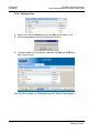
1
ILX56-MM
ControlLogix Platform
InRAx Message Manager for
Industrial Communication
February 6, 2012
USER MANUAL
Your Feedback Please
We always want you to feel that you made the right decision to use our products. If you have suggestions, comments,
compliments or complaints about our products, documentation, or support, please write or call us.
How to Contact Us
ProSoft Technology
5201 Truxtun Ave., 3rd Floor
Bakersfield, CA 93309
+1 (661) 716-5100
+1 (661) 716-5101 (Fax)
www.prosoft-technology.com
[email protected]
Copyright © 2012 ProSoft Technology, Inc., all rights reserved.
ILX56-MM User Manual
February 6, 2012
®
®
®
®
®
ProSoft Technology , ProLinx , inRAx , ProTalk , and RadioLinx are Registered Trademarks of ProSoft
Technology, Inc. All other brand or product names are or may be trademarks of, and are used to identify products
and services of, their respective owners.
ProSoft Technology® Product Documentation
In an effort to conserve paper, ProSoft Technology no longer includes printed manuals with our product shipments.
User Manuals, Datasheets, Sample Ladder Files, and Configuration Files are provided on the enclosed CD-ROM,
and are available at no charge from our web site: www.prosoft-technology.com
Printed documentation is available for purchase. Contact ProSoft Technology for pricing and availability.
North America: +1.661.716.5100
Asia Pacific: +603.7724.2080
Europe, Middle East, Africa: +33 (0) 5.3436.87.20
Latin America: +1.281.298.9109
Important Safety Information
WARNING – EXPLOSION HAZARD – DO NOT DISCONNECT EQUIPMENT UNLESS POWER HAS BEEN
SWITCHED OFF OR THE AREA IS KNOWN TO BE NON-HAZARDOUS.
AVERTISSEMENT – RISQUE D'EXPLOSION – AVANT DE DÉCONNECTER L'EQUIPMENT, COUPER LE
COURANT OU S'ASSURER QUE L'EMPLACEMENT EST DÉSIGNÉ NON DANGEREUX.
Markings
CSA/cUL
C22.2 No. 213-1987
CSA CB Certified
IEC61010
243333
Temp Code T5
0° C <= Ta <= 60° C
Warnings
North America Warnings
A
B
Warning - Explosion Hazard - Substitution of components may impair suitability for Class I, Division 2.
Warning - Explosion Hazard - When in Hazardous Locations, turn off power before replacing or rewiring
modules.
Warning - Explosion Hazard - Do not disconnect equipment unless power has been switched off or the area is
known to be nonhazardous.
Conditions of Safe Usage:
Power, Input, and Output (I/O) wiring must be in accordance with the authority having jurisdiction
A Warning - Explosion Hazard - When in hazardous locations, turn off power before replacing or wiring modules.
B Warning - Explosion Hazard - Do not disconnect equipment unless power has been switched off or the area is
known to be non-hazardous.
C These products are intended to be mounted in an IP54 enclosure. The devices shall provide external means to
prevent the rated voltage being exceeded by transient disturbances of more than 40%.
D DO NOT OPEN WHEN ENERGIZED.
Electrical Ratings
Backplane Current Load: 1000 mA @ 5 V DC
Operating Temperature: 0 to 60°C (32 to 140°F)
Storage Temperature: -40 to 80°C (-40 to 176°F)
Shock: 30g Operational; 50g non-operational; Vibration: 5 g from 10 to 150 Hz
Relative Humidity 5% to 95% (non-condensing)
All phase conductor sizes must be at least 1.3 mm (squared) and all earth ground conductors must be at least
4mm (squared).
Battery Life Advisory
This module uses a Lithium Vanadium Pentoxide battery to backup the date/time settings of the real-time clock and
the BIOS settings in CMOS. The battery recharges whenever the module is receiving power and should not need to
be replaced for the life of the module. The module must be powered for approximately twenty hours before the
battery becomes fully charged.
If the module is left in an unpowered state for approximately 21 or more days, the battery will be completely drained
and the module BIOS, date, and time will revert to their default settings. Before you remove a module from its power
source, ensure the battery is fully charged. You can tell the battery is fully charged when the Battery State (ERR) LED
is OFF.
Note: The battery is not user-replaceable.
ILX56-MM ♦ ControlLogix Platform
InRAx Message Manager for Industrial Communication
Contents
User Manual
Contents
Your Feedback Please ........................................................................................................................ 2
How to Contact Us .............................................................................................................................. 2
®
ProSoft Technology Product Documentation .................................................................................... 2
Important Safety Information............................................................................................................... 3
Warnings ............................................................................................................................................. 3
Battery Life Advisory ........................................................................................................................... 4
Guide to the ILX56-MM User Manual
1
Start Here
1.1
1.2
1.3
1.4
1.5
1.6
1.7
1.8
2
11
Overview.................................................................................................................. 12
Deployment Checklist.............................................................................................. 13
System Requirements ............................................................................................. 14
Package Contents ................................................................................................... 15
Setup Jumper .......................................................................................................... 16
Install the Module in the Rack ................................................................................. 17
Connect to the Module's Web page ........................................................................ 18
Logging In ................................................................................................................ 20
Administration
2.1
2.2
2.3
2.4
2.5
2.6
2.7
3
2.6.1
2.6.2
2.6.3
2.6.4
3.3
3.4
3.2.1
3.2.2
3.2.3
3.3.1
3.3.2
3.3.3
3.3.4
3.4.1
ProSoft Technology, Inc.
February 6, 2012
21
Device Information .................................................................................................. 22
Network Settings ..................................................................................................... 23
System Functions .................................................................................................... 25
Time Sync ............................................................................................................... 27
Audit Log ................................................................................................................. 29
User Administration ................................................................................................. 30
Security.................................................................................................................... 31
Adding a New User ................................................................................................. 32
Editing an Existing User .......................................................................................... 33
Deleting a User ........................................................................................................ 34
Scanner Modes ....................................................................................................... 35
Configure the ILX56-MM module
3.1
3.2
9
37
Editing Configuration Objects .................................................................................. 39
Interfaces and Devices ............................................................................................ 40
Allen-Bradley PLCs ................................................................................................. 41
Siemens Step 7 (S7) PLCs ..................................................................................... 45
Modbus TCP/IP (Schneider Electric Quantum PLCs) ............................................. 46
Tags......................................................................................................................... 49
ControlLogix, CompactLogix, FlexLogix .................................................................. 50
PLC5, MicroLogix and SLC ..................................................................................... 51
Schneider Electric Quantum PLCs .......................................................................... 52
Siemens S7 ............................................................................................................. 53
Transfer Lists ........................................................................................................... 55
Data Conversion During Transfers .......................................................................... 55
Page 5 of 112
Contents
User Manual
3.5
3.6
3.7
3.8
4
ILX56-MM ♦ ControlLogix Platform
InRAx Message Manager for Industrial Communication
3.4.2
3.4.3
3.5.1
3.5.2
3.5.3
Editing Transfer Lists .............................................................................................. 56
Execution of Transfer Lists ..................................................................................... 56
Triggers ................................................................................................................... 57
Hysteresis Example ................................................................................................ 58
Range Example ...................................................................................................... 58
Trigger Scanning .................................................................................................... 58
Saving the Configuration ........................................................................................ 59
Reloading the Configuration ................................................................................... 60
Resetting the Configuration .................................................................................... 61
Verify Communication
4.1
4.2
4.3
5
Viewing Data Transfer Statistics in the ILX56-MM Module .................................... 64
Viewing Trigger Statistics in the ILX56-MM Module ............................................... 65
Viewing Controller Tags .......................................................................................... 66
Diagnostics and Troubleshooting
5.1
5.2
5.3
6
5.3.1
5.3.2
5.3.3
5.3.4
5.3.5
5.3.6
Reference
6.1
6.2
6.3
6.4
63
6.1.1
6.1.2
6.1.3
6.1.4
6.1.5
6.1.6
6.3.1
6.3.2
6.3.3
6.3.4
6.3.5
6.3.6
6.3.7
6.3.8
6.4.1
6.4.2
6.4.3
6.4.4
6.4.5
Page 6 of 112
67
Cannot Log in.......................................................................................................... 68
Setup Mode............................................................................................................. 69
Status ...................................................................................................................... 70
Device Status .......................................................................................................... 70
Runtime Status ....................................................................................................... 71
Tranferring Diagnostic Information from MM to a Controller on the Network ......... 76
Event Logs .............................................................................................................. 79
Chassis Status ........................................................................................................ 80
Resource Status ..................................................................................................... 81
83
Product Specifications ............................................................................................ 84
Functional Overview ............................................................................................... 84
Triggers ................................................................................................................... 84
Transfer Lists .......................................................................................................... 86
Data Transfer .......................................................................................................... 86
Bridging ................................................................................................................... 87
Configuration Editor ................................................................................................ 87
Tag Filters ............................................................................................................... 88
Base Data Type Conversion Rules ........................................................................ 90
Boolean ................................................................................................................... 90
INT8, UINT8, CHAR, or BYTE ................................................................................ 90
INT16, UINT16, or WORD ...................................................................................... 91
INT32, UINT32, or DWORD ................................................................................... 91
INT64, UINT64, or QWORD ................................................................................... 92
Float32 .................................................................................................................... 92
Float64 .................................................................................................................... 92
String ....................................................................................................................... 93
Errors ...................................................................................................................... 94
Level 0: Permanent Errors ...................................................................................... 94
Level 1: Clearable Errors ........................................................................................ 95
Level 2: Warnings ................................................................................................... 95
Level 3: Informational Events ................................................................................. 95
Level 4 Verbose Informational Events .................................................................... 95
ProSoft Technology, Inc.
February 6, 2012
ILX56-MM ♦ ControlLogix Platform
InRAx Message Manager for Industrial Communication
6.4.6
6.4.7
6.4.8
7
Contents
User Manual
Operation of Transfer Status ................................................................................... 96
Commonly Posted Context Strings ....................................................................... 102
Clearing the Error Counts...................................................................................... 102
Support, Service & Warranty
103
Contacting Technical Support ......................................................................................................... 103
7.1
Return Material Authorization (RMA) Policies and Conditions.............................. 105
7.1.1
Returning Any Product .......................................................................................... 105
7.1.2
Returning Units Under Warranty ........................................................................... 106
7.1.3
Returning Units Out of Warranty ........................................................................... 106
7.2
LIMITED WARRANTY........................................................................................... 107
7.2.1
What Is Covered By This Warranty ....................................................................... 107
7.2.2
What Is Not Covered By This Warranty ................................................................ 108
7.2.3
Disclaimer Regarding High Risk Activities ............................................................ 108
7.2.4
Intellectual Property Indemnity .............................................................................. 109
7.2.5
Disclaimer of all Other Warranties ........................................................................ 109
7.2.6
Limitation of Remedies ** ...................................................................................... 110
7.2.7
Time Limit for Bringing Suit ................................................................................... 110
7.2.8
No Other Warranties ............................................................................................. 110
7.2.9
Allocation of Risks ................................................................................................. 110
7.2.10
Controlling Law and Severability ........................................................................... 110
Index
ProSoft Technology, Inc.
February 6, 2012
111
Page 7 of 112
Contents
User Manual
Page 8 of 112
ILX56-MM ♦ ControlLogix Platform
InRAx Message Manager for Industrial Communication
ProSoft Technology, Inc.
February 6, 2012
ILX56-MM ♦ ControlLogix Platform
InRAx Message Manager for Industrial Communication
Guide to the ILX56-MM User Manual
User Manual
Guide to the ILX56-MM User Manual
Function
Section to Read
Details
Introduction
(Must Do)
→
Start Here (page 10) This Section introduces the customer to the
module. Included are: package contents,
system requirements, and hardware installation.
Logging In,
Administration and
Module Configuration
→
Logging In (page 20) This section describes how to log in, how to
Administration (page administer the module, and how to configure
the module.
21)
Configuration (page
37)
Verify Communication
Diagnostic and
Troubleshooting
→
Verifying
Communication
(page 63)
Diagnostics and
Troubleshooting
(page 67)
Reference
Product Specifications
Functional Overview
Glossary
→
Reference (page 83) These sections contain general references
Functional Overview associated with this product, Specifications, and
the Functional Overview.
Product
Specifications
Support, Service, and
Warranty
Index
→
Support, Service
and Warranty (page
103)
ProSoft Technology, Inc.
February 6, 2012
This section describes how to verify
communications with the network. Diagnostic
and Troubleshooting procedures.
This section contains Support, Service and
Warranty information.
Index of chapters.
Page 9 of 112
Guide to the ILX56-MM User Manual
User Manual
Page 10 of 112
ILX56-MM ♦ ControlLogix Platform
InRAx Message Manager for Industrial Communication
ProSoft Technology, Inc.
February 6, 2012
ILX56-MM ♦ ControlLogix Platform
InRAx Message Manager for Industrial Communication
1
Start Here
User Manual
Start Here
In This Chapter
Overview ............................................................................................... 12
Deployment Checklist ............................................................................ 13
System Requirements ........................................................................... 14
Package Contents ................................................................................. 15
Setup Jumper ........................................................................................ 16
Install the Module in the Rack ............................................................... 17
Connect to the Module's Web page....................................................... 18
Logging In.............................................................................................. 20
To get the most benefit from this User Manual, you should have the following
skills:
Rockwell Automation® RSLogix™ software: launch the program, configure
ladder logic, and transfer the ladder logic to the processor
Microsoft Windows: install and launch programs, execute menu commands,
navigate dialog boxes, and enter data
Hardware installation and wiring: install the module and safely connect
Message Manager and ControlLogix devices to a power source and to the
ILX56-MM module's application ports
Caution: You must be able to complete the application without exposing personnel or
equipment to unsafe or inappropriate working conditions.
ProSoft Technology, Inc.
February 6, 2012
Page 11 of 112
Start Here
User Manual
1.1
ILX56-MM ♦ ControlLogix Platform
InRAx Message Manager for Industrial Communication
Overview
The ILX56-Message Manager is a communications interface that can be installed
in a Rockwell Automation® ControlLogix® 1756 chassis to provide data transfer
functionality between automation systems based on a diverse range of
controllers and processors. Supported systems include:
Rockwell Automation (RA) ControlLogix Programmable Automation Controller
(PAC) systems
RA CompactLogix™ (CPLX) PAC systems
Allen-Bradley® (A-B) PLC5® systems
A-B SLC™ systems
A-B MicroLogix™ systems
Siemens Step 7® systems with Industrial Ethernet communications (does not
support configured TSAP connections)
Schneider Electric® Quantum™ PLC systems with Modbus TCP/IP
communications
Any devices that support Modbus TCP/IP Protocol
Page 12 of 112
ProSoft Technology, Inc.
February 6, 2012
ILX56-MM ♦ ControlLogix Platform
InRAx Message Manager for Industrial Communication
1.2
Start Here
User Manual
Deployment Checklist
Before you begin configuring the module, consider the following questions. Your
answers will help you determine the scope of your project and the configuration
requirements for a successful deployment.
1 ____________ Will the ILX56-MM require a static IP address for either or
both Ethernet ports, or will it obtain IP address(es) from a DHCP Server?
Obtain IP address information from your Network Administrator, and then
record the IP Address settings in the following table:
Ethernet Ports
Port 1
Port 2
DHCP? (Yes/No)
Static IP Address
Subnet Mask
Default Gateway
2
3
4
5
6
7
____________ How many controllers and processors will be exchanging data
in your application?
____________ What kinds of processors need to be linked for your
application?
____________ What network protocols are used for the links?
____________ What types of user accounts do you need to create? Users
(to modify configurations) or Administrators (to control configuration access)
____________ Which data transfers should happen on a regular timedinterval basis? Which transfers should happen only on data change or logic
events?
____________ Do you need controllers or other communications modules
installed in the same chassis as the ILX56-MM?
ProSoft Technology, Inc.
February 6, 2012
Page 13 of 112
Start Here
User Manual
1.3
ILX56-MM ♦ ControlLogix Platform
InRAx Message Manager for Industrial Communication
System Requirements
The ILX56-MM module requires the following minimum hardware and software
components:
Rockwell Automation® ControlLogix™ processor, with compatible power
supply and one free slot in the rack for the ILX56-MM module. The module
requires 1 Amp of available 5 VDC power
Rockwell Automation RSLogix 5000 programming software version 16 or
higher
Rockwell Automation RSLinx communication software version 2.51 or higher
Pentium® II 450 MHz minimum. Pentium III 733 MHz (or higher)
recommended
Supported operating systems:
o Microsoft Windows Vista
o Microsoft Windows XP Professional with Service Pack 1 or 2
o Microsoft Windows 2000 Professional with Service Pack 1, 2, or 3
o Microsoft Windows Server 2003
Microsoft Internet Explorer version 7, or higher. Other web browsers are not
supported at this time
128 Mbytes of RAM minimum, 256 Mbytes of RAM recommended
100 Mbytes of free hard disk space (or more based on application
requirements)
256-color VGA graphics adapter, 800 x 600 minimum resolution (True Color
1024 × 768 recommended)
CD-ROM drive
Note: The Hardware and Operating System requirements in this list are the minimum
recommended to install and run software provided by ProSoft Technology. Other third party
applications may have different minimum requirements. Refer to the documentation for any third
party applications for system requirements.
Page 14 of 112
ProSoft Technology, Inc.
February 6, 2012
ILX56-MM ♦ ControlLogix Platform
InRAx Message Manager for Industrial Communication
1.4
Start Here
User Manual
Package Contents
The following components are included with your ILX56-MM module, and are all
required for installation and configuration.
Important: Before beginning the installation, please verify that all of the following items are
present.
Qty.
Part Name
Part Number
Part Description
1
ILX56-MM Module
ILX56-MM
InRAx Message Manager for Industrial
Communication
1
ProSoft Solutions CD
CD-014
Contains sample programs, utilities, and
documentation for the ILX56-MM module.
1
Cable
RL-CBL025
5 foot Ethernet Straight-Through Cable
(Gray)
If any of these components are missing, please contact ProSoft Technology
Support for replacement parts.
ProSoft Technology, Inc.
February 6, 2012
Page 15 of 112
Start Here
User Manual
1.5
ILX56-MM ♦ ControlLogix Platform
InRAx Message Manager for Industrial Communication
Setup Jumper
There is one SETUP JUMPER located on the back of the module, labeled J1. The
Setup Jumper acts as "write protection" for the module's firmware. In "write
protected" mode, the Setup pins are not connected, and the module's firmware
cannot be overwritten.
The following illustration shows the ILX56-MM jumper configuration, with the
Setup Jumper OFF.
If you need to update the firmware, apply the Setup jumper to both pins.
Note: If you are installing the module in a remote rack, you may prefer to leave the Setup pins
jumpered. That way, you can update the module's firmware without requiring physical access to the
module.
Page 16 of 112
ProSoft Technology, Inc.
February 6, 2012
ILX56-MM ♦ ControlLogix Platform
InRAx Message Manager for Industrial Communication
1.6
Start Here
User Manual
Install the Module in the Rack
If you have not already installed and configured your ControlLogix processor and
power supply, please do so before installing the ILX56-MM module. Refer to your
Rockwell Automation product documentation for installation instructions.
Warning: You must follow all safety instructions when installing this or any other electronic
devices. Failure to follow safety procedures could result in damage to hardware or data, or even
serious injury or death to personnel. Refer to the documentation for each device you plan to
connect to verify that suitable safety procedures are in place before installing or servicing the
device.
After you have checked the placement of the jumper, insert ILX56-MM into the
ControlLogix chassis. Use the same technique recommended by Rockwell
Automation to remove and install ControlLogix modules.
You can install or remove ControlLogix system components while chassis power
is applied and the system is operating. However, please note the following
warning.
Warning: When you insert or remove the module while backplane power is on, an electrical arc
can occur. An electrical arc can cause personal injury or property damage by:
sending an erroneous signal to your system's actuators causing unintended machine motion or
loss of process control
causing an explosion in a hazardous environment
Verify that power is removed or the area is non-hazardous before proceeding. Repeated electrical
arcing causes excessive wear to contacts on both the module and its mating connector. Worn
contacts may create electrical resistance that can affect module operation.
1
Align the module with the top and bottom guides, and then slide it into the
rack until the module is firmly against the backplane connector.
2
3
With a firm but steady push, snap the module into place.
Check that the holding clips on the top and bottom of the module are securely
in the locking holes of the rack.
Turn power ON.
4
Note: If you insert the module improperly, the system may stop working, or may behave
unpredictably.
ProSoft Technology, Inc.
February 6, 2012
Page 17 of 112
Start Here
User Manual
1.7
ILX56-MM ♦ ControlLogix Platform
InRAx Message Manager for Industrial Communication
Connect to the Module's Web page
If your network is configured to use IP addresses in the range 192.168.1.xxx,
open Microsoft Internet Explorer (version 7, or higher), and connect to the
following address:
http://192.168.1.254
If your network is configured to use a different IP range, follow these steps:
1 Disconnect your PC from the network
2 Connect the Ethernet cable between the Ethernet port on your PC and Port 1
on the module
3
Temporarily change the IP address and Subnet Mask on your PC to match
the network configuration on the module:
IP address: 192.168.1.1
Subnet mask: 255.255.255.0
Important: Make a note of your IP Address settings. You will need to restore these settings before
you reconnect to the network.
4
5
6
7
8
Open Microsoft Internet Explorer (version 7, or higher) and connect to the
following address:
http://192.168.1.254
Click the LOGIN button at the bottom of the screen, and use the following
username and password to login.
Username: admin
Password: admin
Click the ADMINISTRATION tab, and then the NETWORK tab. Configure the IP
Address, Subnet Mask, and Default Gateway to work with your network.
Click the SAVE button to apply the updated settings.
Change the IP Address and Subnet Mask settings on your PC back to their
original values, and then reconnect your PC to the network.
Page 18 of 112
ProSoft Technology, Inc.
February 6, 2012
ILX56-MM ♦ ControlLogix Platform
InRAx Message Manager for Industrial Communication
Start Here
User Manual
9 Connect to the module's web page again at the module's new IP address.
The following table describes the default Ethernet port configuration and login
information.
Factory Default settings
Ethernet Ports:
Port 1
Port 2
IP:
192.168.1.254.
DHCP
User Name:
admin
Password:
admin
Important: The User Name and Password are case-sensitive.
ProSoft Technology, Inc.
February 6, 2012
Page 19 of 112
Start Here
User Manual
1.8
ILX56-MM ♦ ControlLogix Platform
InRAx Message Manager for Industrial Communication
Logging In
You can view the status and configuration of the ILX56-MM module without
logging in. However, to modify the module's configuration, or to perform
maintenance tasks, you must log in.
The LOGIN and LOGOUT buttons are located in the status bar at the bottom of the
module's web page.
To Log In
Click the
LOGIN button on the status bar at the bottom of the page.
Note: Only one user can be logged into the module at a time.
To Log Out
Click the
LOGOUT button on the status bar at the bottom of the page.
Note: When you close the browser, you are automatically logged out of the module.
If you attempt to log out of the module without saving changes that you have
made, you are prompted to save or cancel the changes.
Click OK to save the changes. Click CANCEL to discard the changes without
saving.
Page 20 of 112
ProSoft Technology, Inc.
February 6, 2012
ILX56-MM ♦ ControlLogix Platform
InRAx Message Manager for Industrial Communication
2
Administration
User Manual
Administration
In This Chapter
Device Information ................................................................................ 22
Network Settings ................................................................................... 23
System Functions .................................................................................. 25
Time Sync ............................................................................................. 27
Audit Log ............................................................................................... 29
User Administration ............................................................................... 30
Scanner Modes ..................................................................................... 35
The ADMINISTRATION page allows you to view or modify administration functions.
The following table describes the tabs on the Administration page.
Tab
Function
Device
Configure device information.
Network
Configure the network ports.
System
Execute system functions.
Time Sync
Configure the time on the module
Configure time synchronization for the controllers.
Audit Log
View the audit log. The audit log consists of system operational events that
have occurred since the module was first started. For example, whenever
the system mode is changed from run to idle or idle to run, this event will be
in the log.
Users
Create and manage user accounts.
You must be logged in with Administrator privilege to view this tab.
Note: You must be logged on as a user with Administrator privilege to modify the settings on this
page.
See also Security (page 31).
ProSoft Technology, Inc.
February 6, 2012
Page 21 of 112
Administration
User Manual
2.1
ILX56-MM ♦ ControlLogix Platform
InRAx Message Manager for Industrial Communication
Device Information
To open the DEVICE INFORMATION page, click the ADMINISTRATION tab, and then
click the DEVICE tab.
The following table describes the fields on the DEVICE INFORMATION tab. The
values you enter here are displayed on the Device Status page (page 70).
Field
Description
Name
Name of the module.
Description
Description of the module.
Location
Location of the module.
Contact
The person responsible for the module.
Click the SAVE button to save your changes.
Note: You must be logged on as a user with Administrator privilege to modify the settings on this
page.
See also Administration (page 21).
Page 22 of 112
ProSoft Technology, Inc.
February 6, 2012
ILX56-MM ♦ ControlLogix Platform
InRAx Message Manager for Industrial Communication
2.2
Administration
User Manual
Network Settings
To open the NETWORK SETTINGS page, click the ADMINISTRATION tab, and then
click the NETWORK tab.
The module has two RJ45 Ethernet ports, located at the bottom of the front panel
on the module. You can configure the following settings for each port.
Disabled
Static IP Address
o Subnet Mask
o Default Gateway (optional)
DHCP (auto-configured through a DHCP server)
Click the SAVE button to update these settings on the module.
Note: The only way to use both ports on the same subnet or Ethernet is to use a redundant wire
solution. Without this each port must be on a separate Ethernet network.
ProSoft Technology, Inc.
February 6, 2012
Page 23 of 112
Administration
User Manual
ILX56-MM ♦ ControlLogix Platform
InRAx Message Manager for Industrial Communication
When you save the network settings, the module will log you out.
Click the RECONNECT button, or press [F5] to reconnect to the module.
If you lose connection with the module, you can put the module in Setup Mode to
temporarily set the network port settings back to the default values (page 16).
This will allow you to connect to the module and correct the network settings.
Note: You must be logged on as a user with Administrator privilege to modify the settings on this
page.
Page 24 of 112
ProSoft Technology, Inc.
February 6, 2012
ILX56-MM ♦ ControlLogix Platform
InRAx Message Manager for Industrial Communication
2.3
Administration
User Manual
System Functions
To open the SYSTEM FUNCTIONS page, click the ADMINISTRATION tab, and then
click the SYSTEM tab.
ProSoft Technology, Inc.
February 6, 2012
Page 25 of 112
Administration
User Manual
ILX56-MM ♦ ControlLogix Platform
InRAx Message Manager for Industrial Communication
System functions you can execute on the module include
Function
Description
Backup
Choose which settings from the module you would like to backup by
checking CONFIGURATION and/or ADMINISTRATIVE SETTINGS. Then click the
BACKUP button to backup the current module configuration(s) to a file on
your computer.
ADMINISTRATIVE SETTINGS backs up all module configuration settings,
including network settings, device name, and so on.
CONFIGURATION backs up the only the information that pertains to the
transfer of data. You can then use this backup file to configure another
module with the same settings.
Restore
Click the BROWSE button to select a previously saved configuration file
from your computer.
Click the RESTORE button to restore the module to the state saved in the
configuration file.
The module is rebooted after the configuration is restored. You will be
prompted to confirm the configuration restore and reboot.
Set Log Level
Set the log level at which the scanner module will record events.
Level 1 logs errors only. This is the recommended setting for most
applications.
Levels 2 through 4 log informational events in increasing detail. Use
these levels for troubleshooting and support.
Level 0 logs only internal system errors.
The scanner must be restarted before the new log level will take effect.
Click the REINITIALIZE button to restart the scanner. You will be prompted
to confirm the reinitialize.
Clear Event Logs
Clears the entire Event Log from the module. This cannot be undone.
Update
You can update the module's firmware from this page. You should only
update the firmware if you have been directed to do so by ProSoft
Technical Support.
Click the BROWSE button to select the firmware file on your computer.
Firmware files have the file extension "fwa".
Click the UPDATE button to perform the update on the module. You will be
prompted to confirm the update.
IMPORTANT: Do not cycle power or disconnect the
Ethernet cable until the update is complete.
Important: You must clear your browser's cache (Tools/Delete Browsing
History/Temporary Internet Files) after rebooting the module to ensure
the old pages have been cleared from your browser's memory.
Reboot
Click the REBOOT button to reboot the module. You will be prompted to
confirm the reboot.
Note: You must be logged on as a user with Administrator privilege to modify the settings on this
page.
Page 26 of 112
ProSoft Technology, Inc.
February 6, 2012
ILX56-MM ♦ ControlLogix Platform
InRAx Message Manager for Industrial Communication
2.4
Administration
User Manual
Time Sync
To open the TIME SYNC page, click the ADMINISTRATION tab, and then click the
TIME SYNC tab.
ProSoft Technology, Inc.
February 6, 2012
Page 27 of 112
Administration
User Manual
ILX56-MM ♦ ControlLogix Platform
InRAx Message Manager for Industrial Communication
The ILX56-MM module can acquire a time signal from an SNTP time server on
the Internet, or from the ControlLogix processor in the same rack with the ILX56MM.
The ILX56-MM can also set the time on ControlLogix, CompactLogix, and
FlexLogix processors defined as Devices.
Note: The module will only obtain, and push, time while in RUN mode.
Field
Description
Timezone
Select the time zone for the module.
Source
The module can poll one or more sources for a time signal.
TIME SOURCES specify the IP addresses for the time synchronization. The
module will attempt to synchronize with each of these sources in the
specified order until it is successful.
TIMEOUT is the number of seconds the module will wait to receive the time
signal from each source.
Destination
Select other devices that will be synchronized to the time on the module.
The items on this list are derived from the devices you have defined in
the Configuration Editor.
Frequency
Specify how often the module will receive and send time synchronization.
A Time Sync cycle will be started when the module is switched to Run.
Click the SAVE button to save your Time settings to the module.
Manual Time Set
Set the time and date, and then click the SET MANUAL TIME button.
To synchronize the time and date on the module to the time and date on
your local computer, click the SYNC CURRENT TIME button.
Note: You must be logged on as a user with Administrator privilege to modify the settings on this
page.
Page 28 of 112
ProSoft Technology, Inc.
February 6, 2012
ILX56-MM ♦ ControlLogix Platform
InRAx Message Manager for Industrial Communication
2.5
Administration
User Manual
Audit Log
To open the AUDIT LOG page, click the ADMINISTRATION tab, and then click the
AUDIT LOG tab.
The audit log is a chronological log of operational system events that have
occurred since the module was first started. The audit log displays 50 records per
page, in order from newest, at the top, to oldest, at the bottom.
The Audit Log records the following types of events
Changing the module's operational mode
Modifying the configuration
Changing the event log level
Reinitializing the module
Backing up the configuration
Restoring the configuration
Updating the module
Other less frequent system events
Operation
Description
Next 50
Click the NEXT 50 button to view the 50 events that occurred prior to the
current 50 events begin displayed.
Previous 50
Click the PREVIOUS 50 button to view the 50 events that occurred after
the current 50 events begin displayed.
See also Security (page 31), Setup Mode (page 69), Administration (page 21).
ProSoft Technology, Inc.
February 6, 2012
Page 29 of 112
Administration
User Manual
2.6
ILX56-MM ♦ ControlLogix Platform
InRAx Message Manager for Industrial Communication
User Administration
To open the USER ADMINISTRATION page, click the ADMINISTRATION tab, then click
the USERS tab.
Note: You must be logged on as a user with Administrator privilege to modify the settings on this
page.
Page 30 of 112
ProSoft Technology, Inc.
February 6, 2012
ILX56-MM ♦ ControlLogix Platform
InRAx Message Manager for Industrial Communication
Administration
User Manual
2.6.1 Security
The ILX56-MM provides three levels of security:
GUEST: No user login account is required.
PROJECT: You must be logged in as a user with Project privilege
ADMINISTRATOR. You must be logged in as a user with Administrator privilege.
Note: When you close the browser, you are automatically logged out. If you have problems logging
in, double-check your username and password. The Login dialog will notify you if the username is
not correct or the password is not correct. If you are sure you are using your correct username and
password and you still cannot log in, see Cannot Login (page 68).
The following table describes functions that require security privilege.
Location
Function
Privilege Required
Status Bar
Set Mode
Project
Configuration Editor
All Functions
Project
Administration
All Functions
Administrator
Administration/Users
This page cannot be viewed without
Administrator privilege
Administrator
Note: Administrator privilege includes all Project privilege functions.
When you receive a new module, it comes configured with one default user who
has Administrator privileges (full access to all module functions).
Username: admin
Password: admin
After configuring your user and administrator accounts, you should delete the
default "admin" user for additional security.
If you forget your username and/or password you can reset the admin password
(page 16). If you have deleted the default admin user, the default admin user will
be restored with Administrator privilege.
ProSoft Technology, Inc.
February 6, 2012
Page 31 of 112
Administration
User Manual
ILX56-MM ♦ ControlLogix Platform
InRAx Message Manager for Industrial Communication
2.6.2 Adding a New User
1
Click NEW to add a new user. This action opens the NEW USER INFO dialog
box.
2
3
4
5
6
Enter the User Name for the user.
Select the desired Privilege for the user: Project or Administrator.
Enter a Password for the user.
Enter the password again in the Confirm Password field.
Click OK to add the new user.
Page 32 of 112
ProSoft Technology, Inc.
February 6, 2012
ILX56-MM ♦ ControlLogix Platform
InRAx Message Manager for Industrial Communication
Administration
User Manual
2.6.3 Editing an Existing User
1
Select a user and click the EDIT button. This action opens the EDIT USER INFO
dialog box
2
You can change the Username, Privilege, or Password.
If you change the password, you must also enter the new password in the
Confirm Password edit box.
ProSoft Technology, Inc.
February 6, 2012
Page 33 of 112
Administration
User Manual
ILX56-MM ♦ ControlLogix Platform
InRAx Message Manager for Industrial Communication
2.6.4 Deleting a User
1
2
Select a user and click DELETE, or press the [DEL] key to delete a user.
You will be prompted to confirm the deletion of the user.
3
To select multiple users for deletion, hold down the [SHIFT] or [CTRL] key
while selecting users.
See also Security (page 31), Setup Mode (page 69), Administration (page 21).
Page 34 of 112
ProSoft Technology, Inc.
February 6, 2012
ILX56-MM ♦ ControlLogix Platform
InRAx Message Manager for Industrial Communication
2.7
Administration
User Manual
Scanner Modes
The scanner mode controls the scanning of Triggers (page 57) and the transfer
of data between Devices. The scanner can be in one of the following modes:
In STOP mode, Triggers are not scanned and none of the Interfaces are
active. The scanner only goes into Stop mode when a serious error has
occurred. You cannot put the scanner into Stop mode yourself.
In IDLE mode, Triggers are not scanned but the Interfaces are active. In Idle
mode, you can configure the scanner using the Configuration Editor.
In RUN mode, Triggers are scanned and the Interfaces are active. Data is
actively transferred between controllers based on Trigger logic. You cannot
configure the scanner while it is in Run mode.
You must be logged into the module with Project or Administrator privilege to
change the scanner mode. To change the scanner mode, click the IDLE
or
RUN
buttons on the status bar at the bottom of the page. The following
illustration shows the ILX56-MM in IDLE mode.
ProSoft Technology, Inc.
February 6, 2012
Page 35 of 112
Administration
User Manual
Page 36 of 112
ILX56-MM ♦ ControlLogix Platform
InRAx Message Manager for Industrial Communication
ProSoft Technology, Inc.
February 6, 2012
ILX56-MM ♦ ControlLogix Platform
InRAx Message Manager for Industrial Communication
3
Configure the ILX56-MM module
User Manual
Configure the ILX56-MM module
In This Chapter
Editing Configuration Objects ................................................................ 39
Interfaces and Devices .......................................................................... 40
Tags ...................................................................................................... 49
Transfer Lists......................................................................................... 55
Triggers ................................................................................................. 57
Saving the Configuration ....................................................................... 59
Reloading the Configuration .................................................................. 60
Resetting the Configuration ................................................................... 61
To open the Configuration Editor page, click the CONFIGURATION EDITOR tab.
Note: To modify the settings on this page, you must be logged on as a user with Administrator or
Project privilege, and the scanner must be in IDLE mode (page 35). If you are not logged in, or if the
scanner is in RUN mode, you can view these settings, but you cannot change them.
ProSoft Technology, Inc.
February 6, 2012
Page 37 of 112
Configure the ILX56-MM module
User Manual
ILX56-MM ♦ ControlLogix Platform
InRAx Message Manager for Industrial Communication
The Configuration Editor page is divided into two panes.
The left pane is a tree view of Interfaces, Transfer Lists and Triggers. Click
the [+] icon next to each object to expand or collapse the tree view.
The right pane shows the properties of objects you select in the tree view.
The following table describes the types of objects you can configure.
Name
Description
Interfaces
Physical objects located in slots in the ControlLogix rack, or physical
objects connected to ports on the module.
Devices
Physical objects (bridges) linking a controller to one of the Interfaces. See
Interfaces and Devices (page 40).
Tags
Individual data objects in the controllers that can be transferred to another
controller. See Tags (page 49).
Triggers
Define when to transfer data from one Interface (programmable controller)
to another. See Triggers (page 57).
Transfer lists
Define what data to transfer between Devices. See Transfer Lists (page
55).
Page 38 of 112
ProSoft Technology, Inc.
February 6, 2012
ILX56-MM ♦ ControlLogix Platform
InRAx Message Manager for Industrial Communication
3.1
Configure the ILX56-MM module
User Manual
Editing Configuration Objects
To use the Configuration Editor, expand the Tree View (left pane), and then
select the object to edit.
Click the NEW button on the toolbar to create a new object under the selected
object.
Click the EDIT button to view or modify the selected object. Or, you can
double-click the selected object in the tree view.
Click the DELETE button to delete the selected object. Or, select an object and
then press the [DEL] key to Delete (permanently remove) the object.
ProSoft Technology, Inc.
February 6, 2012
Page 39 of 112
Configure the ILX56-MM module
User Manual
3.2
ILX56-MM ♦ ControlLogix Platform
InRAx Message Manager for Industrial Communication
Interfaces and Devices
You can configure the module to send and receive tag data to/from controllers in
the local ControlLogix rack, connected remotely through a bridge, or via one of
the Ethernet ports on the module. Interfaces are used to configure controllers or
bridges in the local ControlLogix rack. Devices are used to configure bridges and
controllers that are remotely connected through bridges in the local rack or one of
the Ethernet ports on the module.
Data transferred to or from a PLC 5®, SLC™, or MicroLogix™ may be transferred
via one of the supported bridges or one of the Ethernet ports on the module.
Data transferred to or from a, or ControlLogix® Programmable Automation
Controller (PAC) can be transferred directly to/from a controller in the
ControlLogix rack or to/from a remote ControlLogix PAC via one of the supported
bridges or one of the Ethernet ports on the module.
Data transferred to or from a Siemens Step 7 (S7) PLC or Schneider Electric
Quantum PLC must be done through one of the Ethernet ports of the module.
Use the Configuration Editor to create, modify, or delete Interfaces and Devices.
Select the Interfaces node in the Configuration Editor tree. The content pane will
display a table containing all of the Interfaces.
Click NEW to create a new Interface.
Click EDIT to edit the selected Interface.
Click DELETE or press the [DEL] key to delete the selected Interface.
You can also edit an Interface by double clicking on the Interface in the
Configuration Editor tree or in the content pane.
Page 40 of 112
ProSoft Technology, Inc.
February 6, 2012
ILX56-MM ♦ ControlLogix Platform
InRAx Message Manager for Industrial Communication
Configure the ILX56-MM module
User Manual
3.2.1 Allen-Bradley PLCs
An Allen-Bradley (AB) PLC can be defined as an Interface or as a Device.
A Device defined as an Interface (controller) will contain a Tags node under it
in the Configuration Editor tree. The Tags node contains all the Tags
referenced for that controller.
A Device defined as a Bridge will contain a Devices node under it in the
Configuration Editor tree.
ProSoft Technology, Inc.
February 6, 2012
Page 41 of 112
Configure the ILX56-MM module
User Manual
ILX56-MM ♦ ControlLogix Platform
InRAx Message Manager for Industrial Communication
Each Interface and Device has a unique Name, a Timeout, and addressing
information.
The Timeout specifies the timeout value in milliseconds to be used in
communicating with the device.
The addressing information contains information to address the device on the
network or in the rack where the device is located.
Depending on the Interface Type and Device Type, other parameters may also
be available. The following table describes the addressing parameters for each
interface/device type.
Parameter
Description
Interfaces
Addressing is specified as a slot number.
ControlNet bridge
Addressing is specified as a node number.
DHRIO bridge
Addressing is specified as a channel and node number.
DH485 bridge
Addressing is specified as a channel and node number.
Bridges (ControlLogix Backplane)
Devices are configured under a bridge interface in the local rack. Select the
DEVICES node in the Configuration Editor tree. The content pane will display a
table containing all of the Devices defined for that bridge.
The ILX56-MM supports the following bridges:
EtherNet/IP®
DHRIO
DH485
ControlNet ™
Page 42 of 112
ProSoft Technology, Inc.
February 6, 2012
ILX56-MM ♦ ControlLogix Platform
InRAx Message Manager for Industrial Communication
Configure the ILX56-MM module
User Manual
EtherNet/IP Bridge
A 1756 EtherNet/IP bridge in the local rack can be connected directly to a PLC 5,
SLC, or MicroLogix.
An EtherNet/IP bridge can also be connected to another EtherNet/IP bridge or
CompactLogix PAC in a remote rack.
An EtherNet/IP bridge in a remote rack can be connected to a ControlLogix PAC
in that rack or an EtherNet/IP bridge, ControlNet bridge, DHRIO bridge, or
DH485 bridge in that remote rack.
An EtherNet/IP bridge rack can be connected to a CompactLogix PAC.
DHRIO Bridge
A DHRIO bridge in the local rack can be connected directly to a PLC 5 or SLC,
or, connected to another DHRIO bridge in a remote ControlLogix rack.
A DHRIO bridge in a remote rack can be connected to a ControlLogix PAC in
that rack or an EtherNet/IP bridge, ControlNet bridge, DHRIO bridge, or DH485
bridge in that remote rack.
ProSoft Technology, Inc.
February 6, 2012
Page 43 of 112
Configure the ILX56-MM module
User Manual
ILX56-MM ♦ ControlLogix Platform
InRAx Message Manager for Industrial Communication
ControlNet Bridge
A ControlNet bridge in the local rack can be connected directly to a PLC 5 or,
connected to another ControlNet bridge in a remote ControlLogix rack.
A ControlNet bridge in a remote rack can be connected to a ControlLogix PLC in
that rack or an EtherNet/IP bridge, ControlNet bridge, DHRIO bridge, or DH485
bridge in that remote rack.
DH485 Bridge
A DH485 bridge in the local rack can be connected directly to an SLC,
MicroLogix, or ControlLogix PAC, or, connected to another DH485 bridge in a
remote ControlLogix rack.
A DH485 bridge in a remote rack can be connected to a ControlLogix PAC in that
rack or an EtherNet/IP bridge, ControlNet bridge, DHRIO bridge, or DH485
bridge in that remote rack.
Page 44 of 112
ProSoft Technology, Inc.
February 6, 2012
ILX56-MM ♦ ControlLogix Platform
InRAx Message Manager for Industrial Communication
Configure the ILX56-MM module
User Manual
ControlLogix PLC
A ControlLogix PAC in the local rack can be connected through a bridge module
to a PLC 5, SLC, MicroLogix, or ControlLogix PAC, or, connected to another
ControlLogix PAC in a remote ControlLogix rack.
A ControlLogix PAC in a remote rack can be connected to a ControlLogix PAC in
that rack or an EtherNet/IP bridge, ControlNet bridge, DHRIO bridge, or DH485
bridge in that remote rack.
3.2.2 Siemens Step 7 (S7) PLCs
An Interface defined as a Siemens S7 will contain a Tags node under it in the
Configuration Editor tree. The Tags node contains all the Tags referenced for
that controller.
Each Interface has a unique Name, IP address, Remote Rack Number, Remote
Slot Number, number of Retries, and Timeout.
The Timeout specifies the timeout value in milliseconds to be used in
communicating with the device.
The addressing information: IP address, Remote Rack Number, and Remote Slot
Number contains information to address the device on the S7 Industrial Ethernet
network.
ProSoft Technology, Inc.
February 6, 2012
Page 45 of 112
Configure the ILX56-MM module
User Manual
ILX56-MM ♦ ControlLogix Platform
InRAx Message Manager for Industrial Communication
3.2.3 Modbus TCP/IP (Schneider Electric Quantum PLCs)
An Interface defined as Modbus TCP/IP will contain a Devices node under it in
the Configuration Editor tree.
Each Devices node will contain a Tags node under it in the Configuration Editor
tree. The Tags node contains all the Tags referenced for that controller.
Each Interface has a unique Name, IP Address and Timeout. The Timeout
specifies the timeout value in milliseconds to be used in communicating with the
device.
Page 46 of 112
ProSoft Technology, Inc.
February 6, 2012
ILX56-MM ♦ ControlLogix Platform
InRAx Message Manager for Industrial Communication
Configure the ILX56-MM module
User Manual
Each Device has the following unique parameters.
Parameter
Description
Node Address
The Modbus Node Address of the slave device to connect to the
module. If you are connecting to a Quantum PLC via a bridge, enter the
Modbus node address of the device connect to the module. If you are
directly connecting to a Quantum PLC, set this to 0.
Message Idle Time
The idle time between messages in milliseconds. Range is 0 to 50.
Register Addressing Type The type of addressing used to access Long Integers and Floating Point
data, where:
Maximum Data Bytes
ProSoft Technology, Inc.
February 6, 2012
Normal
Longs/Floats occupy two 16-bit registers.
Register order is normal.
Modicon
Longs/Floats occupy two 16-bit registers.
Register addressing order is WORD reversed.
32-bit
Longs/Floats occupy one 32-bit register.
The maximum number of register or coil data bytes contained in a
single MODBUS message body. Valid options are 4, 32, 64, 128, 192,
and 244. If an array tag is larger than this value, multiple messages
may be used to complete the data access.
Page 47 of 112
Configure the ILX56-MM module
User Manual
ILX56-MM ♦ ControlLogix Platform
InRAx Message Manager for Industrial Communication
Parameter
Description
Maximum Data Byte Gap
The byte gap allowed in the reading of the register or coil data block.
Valid options are:
0
No gaps are allowed in the reg/coil data block.
Only sequential contiguous reg/coil read
requests may be combined in a request
message. For example, sequential reads of
Status Bits 10001 and 10003 will result in two
read request messages.
1
Scattered Coil (0x0000) and Status Bit (1x0000)
read requests with up to a 1 byte (8 bit) gap may
be combined in a single request message. For
example, sequential reads of 10001 and 10003
will result in a single request message with
10002 being discarded. Scattered sequential
Holding (4x0000) and Input (3x0000) register
accesses must be contained or exactly
adjacent.
8
Scattered sequential reg/coil read requests that
have up to an 8 byte gap may be combined in
the same read request message.
16
Scattered sequential reg/coil read requests that
have up to a 16 byte gap may be combined in
the same read request message.
32
Scattered sequential reg/coil read requests that
have up to a 32 byte gap may be combined in
the same read request message.
64
Scattered sequential reg/coil read requests that
have up to a 64 byte gap may be combined in
the same read request message.
128
Scattered sequential reg/coil read requests that
have up to a 128 byte gap may be combined in
the same read request message.
Single Register Writes
Determines if multiple or single register writes will occur. If this option is
"ON", 16-bit register writes will be executed one at a time, 32-bit writes
will be executed one at a time, and coil writes will be executed one at a
time. Array writes will require multiple messages to complete.
Timeout
The timeout value in milliseconds to be used in communicating with the
device.
You must be logged on as a user with Project or Administrator privilege to modify
the module data transfer configuration.
See also Configuration Editor, Tags
Page 48 of 112
ProSoft Technology, Inc.
February 6, 2012
ILX56-MM ♦ ControlLogix Platform
InRAx Message Manager for Industrial Communication
3.3
Configure the ILX56-MM module
User Manual
Tags
Tags refer to individual data objects in the controllers that can be transferred to
another controller.
Tags can be created and deleted, but cannot be modified. In the Configuration
Editor tree, each controller contains a node named Tags. When you select the
Tags node under any controller, in the content pane a table is displayed
containing all of the Tags currently defined for that controller. The read/write
status of a tag is shown in the last column as a "Read Only" check box. If the
Read Only check box is selected, you cannot use this tag as as a destination in a
transfer list.
When the Tags node is selected, you can add or delete Tags from the controller.
Click NEW to create a new Tag. Click the Delete button to delete the selected
Tag.
For ControlLogix PACs, the actual Tags in the controller are enumerated.
From this enumeration, the user can select which tags to reference in the
module. See also New Tag dialog box (ControlLogix/CompactLogix/Flex
Logix).
For PLC 5, MicroLogix and SLC processors, Tags are created to access
various indexes in the controller files (PLC 5, MicroLogix and SLC). See also
New Tag dialog box (PLC 5, MicroLogix and SLC).
For Siemens S7 and Schneider Electric Quantum PLCs, the tag references
must be entered by the user. Automated enumeration is not supported. See
also New Tag dialog box (Siemens S7) and New Tag dialog box (Schneider
Electric Quantum PLCs).
You must be logged on as a user with Project or Administrator privilege to modify
the module's data transfer configuration.
See also Configuration Editor.
This option allows you to set up transfer lists and these can now be transferred to
other interface devices using other diagnostics tags used in transfer lists. For
additional information for how to use these tags, see Transferring Internal
Diagnostic
Tags.
ProSoft Technology, Inc.
February 6, 2012
Page 49 of 112
Configure the ILX56-MM module
User Manual
ILX56-MM ♦ ControlLogix Platform
InRAx Message Manager for Industrial Communication
3.3.1 ControlLogix, CompactLogix, FlexLogix
You can use the ControlLogix, CompactLogix and FlexLogix NEW TAG dialog box
to add references of Tags to the module's configuration. To open the NEW TAG
dialog box, you select the TAGS node under a ControlLogix, CompactLogix or
FlexLogix controller in the Configuration Editor tree and then click the NEW button
on the toolbar.
When the dialog first comes up, no Tags are displayed in the Tag tree. At the top
of the dialog is an edit box named Tag Filter. Enter a filter for the Tags and click
the GET TAGS button or press the [ENTER] key. All Tags that match the specified
filter will be loaded into the tag tree. Or, to get all Tags, leave the Tag Filter
empty and click the GET TAGS button or press the [ENTER] key. See also Tag
Filter Help (page 88).
After the Tags matching the filter are loaded into the Tag tree, select a Tag. The
Name, Data Type, and Number of Elements associated with the Tag are
displayed on the right hand side of the New Tag dialog box. You cannot modify
any of the Tag values. Click the ADD button to add the Tag reference to the
module's configuration.
Click DONE to close the New Tag dialog box.
See also Tags
Page 50 of 112
ProSoft Technology, Inc.
February 6, 2012
ILX56-MM ♦ ControlLogix Platform
InRAx Message Manager for Industrial Communication
Configure the ILX56-MM module
User Manual
3.3.2 PLC5, MicroLogix and SLC
You can use the PLC5, MicroLogix and SLC New Tag dialog box to add Tags
from a PLC 5, MicroLogix or SLC controller to the module's configuration. To
open the PLC5, MicroLogix and SLC New Tag dialog box, you select the Tags
node under a PLC5, MicroLogix or SLC controller in the Configuration Editor tree
and then click the NEW button on the toolbar.
When the dialog box first comes up, the location tree is loaded with Tag locations
within the controller. For a PLC5, MicroLogix or SLC, these are file references.
Select a Tag location in the location tree. The File Address, Data Type and
Name, associated with the Tag are displayed on the right hand side of the NEW
TAG dialog box. You can modify the name of the tag to a Tag name that is
meaningful to you. You can modify the number of elements to specify how many
data items at this location will be associated with this tag. When number of
elements is greater than 1 this Tag will be handled as an array. Click the ADD
button to add the Tag to module's configuration.
Click DONE to close the PLC5, MicroLogix and SLC NEW TAG dialog box.
See also Tags
ProSoft Technology, Inc.
February 6, 2012
Page 51 of 112
Configure the ILX56-MM module
User Manual
ILX56-MM ♦ ControlLogix Platform
InRAx Message Manager for Industrial Communication
3.3.3 Schneider Electric Quantum PLCs
Use the Modbus TCP/IP New Tag dialog box to add Tags from a Schneider
Electric Quantum PLC (Unity or Concept) controller to the module's configuration.
To open the Modbus TCP/IP New Tag dialog box, you select the Tags node
under a Schneider Electric Quantum PLC controller in the Configuration Editor
tree and then click the NEW button on the toolbar.
The dialog box allows the user to enter the following parameters.
Parameter
Description
Tag Name
The desired name of the tag and is completely at the discretion of the
user. It is suggested that it resemble the tag as it is labeled in the
Schneider Electric Quantum controller.
Register/Coil
The desired area of the state RAM to be accessed. The four areas are
Coils (0x0000), Input Status bits (1x0000), Input register (3x0000), and
Holding Register (4x0000). Each area designation is followed by the
most significant digit of the Concept (direct) address, shown in
parenthesis.
Offset
The desired offset, within the state RAM, of the data to be accessed.
This, coupled with the register/coil selection, will determine the
complete address of the data to be accessed. For example, selecting
Holding Register with an offset of 00180 would produce a final address
of 400180.
Data Type
The desired format for accessing the data. Register/coil types of coil
and input bit can only be accessed as byte_bools. Registers may be
accessed as one of the following:
Int16 - 16-bit Signed Integers
Int32 - 32-bit Signed Long Integers
Uint16 - 16-bit Unsigned Integers
Uint32 - 32-bit Unsigned Long Integers
Float32 - 32-bit Floating Point
Number of Elements
The number of elements to be accessed. This allows for array transfers.
See also Tags
Page 52 of 112
ProSoft Technology, Inc.
February 6, 2012
ILX56-MM ♦ ControlLogix Platform
InRAx Message Manager for Industrial Communication
Configure the ILX56-MM module
User Manual
3.3.4 Siemens S7
Use the Siemens S7 New Tag dialog box to add Tags from a Siemens S7
controller to the module's configuration. To open the Siemens S7 New Tag dialog
box, you select the Tags node under a Siemens S7 controller in the
Configuration Editor tree and then click the NEW button on the toolbar.
The dialog box allows the user to enter the following parameter.
Parameter
Description
Tag Name
The desired name of the tag and is completely at the discretion of the
user. It is suggested that it resemble the tag as it is labeled in the
Siemens S7 controller.
Address Type
The type of memory to be accessed: Input, Output, Peripheral Input,
Flag Bit, Timers, Counters, or Data Blocks.
Input
The memory that contains the last scan of the input modules. The S7
notation (IEC) for this area is "I". This memory is read-only for module
access.
Output
The memory that contains the desired output values to be written to the
output modules at the end of the next scan cycle. The S7 notation (IEC)
for this area is "Q". This memory is read only for module access.
Peripheral Input
The actual physical hardware of the input modules. The S7 notation
(IEC) for this area is "PI". This area is read only for module access.
Flag Bit
The memory that is intended to store interim results calculated in the
program of the PLC. The S7 notation (IEC) for this area is "M". This
memory is read/write for module access.
Timers
The memory that contains the accumulators for the timers in the S7
PLC. The S7 notation (IEC) for the timers is "T". This memory is read
only for module access and the format is in BCD. The number
represents the number of milliseconds that the timer has been active
with a maximum value of 3999.
Counters
The memory that contains the accumulators for the counters in the S7.
The S7 notation (IEC) for the counters is "C". This memory is read only
for module access and the format is in BCD. The number represents
the accumulated value of the counter since the counter has been active
with a maximum value of 999.
ProSoft Technology, Inc.
February 6, 2012
Page 53 of 112
Configure the ILX56-MM module
User Manual
ILX56-MM ♦ ControlLogix Platform
InRAx Message Manager for Industrial Communication
Parameter
Description
Data Blocks
The memory that contains information for the program of the S7 PLC.
They may contain the following data types: BOOL, BYTE, WORD,
DWORD, INT, DINT, REAL, S5TIME, DATE, TIME, TIME_OF_DAY,
CHAR, DATE_AND_TIME, STRING, or ARRAY. Descriptions of these
data types should be available in the S7 PLC or Step 7 Programming
Software documentation. This memory is read/write for module access.
DB Number
The number of the desired Data Block to access. This field is only valid
if the Address Type selected is Data Blocks (DB).
Offset
The desired offset/number of the associated Address Type element.
The following is a description of this field’s meaning for each address
type:
Input,
Enter the slot number of the desired I/O module.
Peripheral Input
& Output
Flag Bit
Enter the byte offset within the Flag Bit memory of
the desired location.
Timers &
Counters
Enter the number of the desired timer or counter.
Data Blocks
Enter the number of the desired data block.
Bit ID
The desired bit number within the data element.
Data Type
The desired format for accessing the data. This field depends on the
selected Address Type. Certain Address Types have limited access and
particular Data Types will be grayed out if not applicable to the selected
Address Type.
String Size
The size of the string to be accessed. Enter the exact size of the string
as it is defined in the S7 PLC. This is only applicable to an Address
Type of STRING.
Click DONE to close the Siemens S7 New Tag dialog box. Click the SAVE button
to save the new tag configuration data.
See also Tags.
Page 54 of 112
ProSoft Technology, Inc.
February 6, 2012
ILX56-MM ♦ ControlLogix Platform
InRAx Message Manager for Industrial Communication
3.4
Configure the ILX56-MM module
User Manual
Transfer Lists
A TRANSFER LIST is a list of Transfers that specify what data is to be transferred
between the programmable controllers.
A Transfer List contains a unique name for the Transfer List, a set of Transfers,
and an On Transfer Error option. The On Transfer Error specifies how the
scanner will handle a transfer. On Transfer Error includes the following error
options:
Parameter
Description
Abort
Abort Transfer List on any Transfer error.
Continue
Abort the Transfer that generated the error, but continue Transfer List
execution.
Retry (default)
Retry the Transfer that generated the error until it succeeds.
A Transfer specifies a Source and a Destination and includes a Sequence
Number, Wait indicator, and a Transfer on Change indicator.
The Source specifies the Tag to read the data from or a numeric or string literal
constant. The Destination specifies the Tag where the data will be transferred to.
The Sequence Number determines the order of execution of the Transfers. The
Wait indicator, if turned on, specifies that the Transfer List will wait for all
previous transfers to complete before starting this transfer. The Transfer on
Change indicator, if turned on, indicates that the transfer will occur whenever the
source data changes. If the Transfer on Change option is selected, the source
data has not changed since the last Transfer List execution, and the source data
is less than 10 seconds old, the Transfer destination tag will not be written. This
optimization can improve performance when writing to slow networks.
When specifying a string constant in the Source, the string constant must begin
and end with a single quote and cannot contain a single quote or double quote as
part of the string to be transferred.
3.4.1 Data Conversion During Transfers
When the data type of a Source is different from the data type of the Destination,
the Source is converted to the data type of the Destination (page 90).
When you are transferring data from one array to another, the dimensions of the
arrays must match in total number of elements. The members are all typeconverted, if required, according to the Base Data Type Conversion Rules. PLC
5, SLC and MicroLogix Tags that specify Number of Elements greater than 1 are
treated as array.
If the Source and Destination are Structures (UDTs), the Source and Destination
structure members are matched by name. If a Source member does not exist in
the Destination, the Source member is ignored. If a Destination member does not
exist in the Source, the transfer is not allowed. The Base Data Type Conversion
Rules apply to the matched members, so, if "PartCount" is a numeric Source
member and a string Destination member, a number to string conversion is
applied during the transfer. Member array dimension total element counts must
match exactly.
ProSoft Technology, Inc.
February 6, 2012
Page 55 of 112
Configure the ILX56-MM module
User Manual
ILX56-MM ♦ ControlLogix Platform
InRAx Message Manager for Industrial Communication
3.4.2 Editing Transfer Lists
Transfer Lists can be created, modified, and deleted in the Configuration Editor.
Select the Transfer Lists node in the Configuration Editor tree. The content pane
will display a table containing all of the Transfer Lists. Click NEW to create a new
Transfer List. Click EDIT to edit the selected Transfer List. Click DELETE to delete
the selected Transfer List. You can also edit a Transfer List by double clicking on
the Transfer List in the Configuration Editor tree or in the content pane.
3.4.3 Execution of Transfer Lists
The Transfers in the Transfer List are executed in the order specified by the
Sequence Number. When you select a Transfer List, the toolbar buttons allow
you to move the Transfers up or down in the order of execution. If you select a
Transfer and then click the NEW button, the new Transfer will be added BEFORE
the selected Transfer. If you add a new Transfer while no Transfers are selected,
the new Transfer will be added to the end of the list.
Page 56 of 112
ProSoft Technology, Inc.
February 6, 2012
ILX56-MM ♦ ControlLogix Platform
InRAx Message Manager for Industrial Communication
3.5
Configure the ILX56-MM module
User Manual
Triggers
Triggers define when the data is transferred from one programmable controller to
another. A Trigger contains the following attributes.
Parameter
Description
Name
The Name that uniquely identifies the Trigger.
Type
Specifies how the Trigger fires. This value is fixed and cannot be
modified.
Scan Period
The rate at which the Trigger will be evaluated.
Condition
The Condition under which the Trigger will fire. Condition can be any of
the following.
Tolerance
ProSoft Technology, Inc.
February 6, 2012
Parameter
Description
ALWAYS
Always fires.
NEVER
Never fires.
CHANGE
Fires on change of state.
LT
Fires when Compare Value 1 < Compare Value
2.
LTE
Fires when Compare Value 1 <= Compare Value
2.
GT
Fires when Compare Value 1 > Compare Value
2.
GTE
Fires when Compare Value 1 >= Compare Value
2.
EQ
Fires when Compare Value 1 = Compare Value
2.
NEQ
Fires when Compare Value 1 <> Compare Value
2.
BAND (Bitwise
AND)
Fires when Compare Value 1 bitwise ANDed
with Compare Value 2 is non zero.
ELT, ELTE, EGT,
EGTE, EEQ,
ENEQ, EBAND
These conditions are the same as the conditions
above, except that these conditions are edge
trigger conditions. They only fire once when the
condition evaluates to true. The trigger will fire
again once, when the condition evaluates to
false and then changes again to true.
Optional comparison Tolerance value (numeric constant).
Ignored for ALWAYS, NEVER, CHANGE, BAND, and EBAND
conditions.
Used as hysteresis value for LT, LTE, GT, GTE, ELT, ELTE, EGT,
and EGTE conditions.
Used as range for EQ, NEQ, EEQ, and ENEQ conditions.
Page 57 of 112
Configure the ILX56-MM module
User Manual
ILX56-MM ♦ ControlLogix Platform
InRAx Message Manager for Industrial Communication
3.5.1 Hysteresis Example
Compare Value 1 = Tag1
Condition = EGT
Compare Value 2 = 212.0
Tolerance = 12.0
Trigger fires once when Tag1 > 212.0.
Trigger arms when Tag1 <= (212.0-12.0).
Trigger fires again once when Tag1 > 212.0.
3.5.2 Range Example
Compare Value 1 = Tag1
Condition = EQ
Compare Value 2 = 212.0
Tolerance = 2.0
Trigger fires when 210.0 <= Tag1 <= 214.0
3.5.3 Trigger Scanning
Triggers are evaluated by the scanner at the rate specified by the Scan Period
attribute. If the Trigger Condition evaluates to TRUE (nonzero), the Trigger is
fired and any associated Transfer Lists are executed.
If multiple Transfer Lists are specified, they are executed simultaneously. After a
Trigger fires, it is disabled until all of the specified Transfer Lists are completed. It
is possible for multiple Triggers to simultaneously fire a single Transfer List.
If an asynchronous Trigger attempts to fire a currently executing Transfer List,
the Transfer List will be marked as pending and restarted as soon as it
completes. The associated Trigger will be disabled until the pending Transfer
Lists start and complete.
If an error occurs while reading the Trigger Compare Value 1, or Compare Value
2 tags, the error will be placed in the active error list, the error will be logged, and
the Trigger will be disabled for a period (usually 5 seconds, to prevent excessive
error logging). If or when a retry of the failed Compare Value 1 / Compare Value
2 read succeeds, the active error will be cleared, but the log entry will remain.
Page 58 of 112
ProSoft Technology, Inc.
February 6, 2012
ILX56-MM ♦ ControlLogix Platform
InRAx Message Manager for Industrial Communication
3.6
Configure the ILX56-MM module
User Manual
Saving the Configuration
When you have completed making changes to the data transfer configuration,
click the SAVE button to save the configuration changes and load them into the
scanner.
You will be prompted to confirm the save of the data transfer configuration.
ProSoft Technology, Inc.
February 6, 2012
Page 59 of 112
Configure the ILX56-MM module
User Manual
3.7
ILX56-MM ♦ ControlLogix Platform
InRAx Message Manager for Industrial Communication
Reloading the Configuration
Click the RELOAD button to discard changes you have made to the data transfer
configuration.
This will reload the last saved configuration. You will be prompted to confirm the
reload of the data transfer configuration.
Page 60 of 112
ProSoft Technology, Inc.
February 6, 2012
ILX56-MM ♦ ControlLogix Platform
InRAx Message Manager for Industrial Communication
3.8
Configure the ILX56-MM module
User Manual
Resetting the Configuration
Click the RESET button to erase the entire data transfer configuration and start
over.
You will be prompted to confirm the erase of the data transfer configuration.
ProSoft Technology, Inc.
February 6, 2012
Page 61 of 112
Configure the ILX56-MM module
User Manual
Page 62 of 112
ILX56-MM ♦ ControlLogix Platform
InRAx Message Manager for Industrial Communication
ProSoft Technology, Inc.
February 6, 2012
ILX56-MM ♦ ControlLogix Platform
InRAx Message Manager for Industrial Communication
4
Verify Communication
User Manual
Verify Communication
In This Chapter
Viewing Data Transfer Statistics in the ILX56-MM Module .................... 64
Viewing Trigger Statistics in the ILX56-MM Module .............................. 65
Viewing Controller Tags ........................................................................ 66
There are several ways to verify that the ILX56-MM module is communicating
with the processor and the network. You can
View Data Transfer Statistics (page 64)
View Trigger Statistics (page 65)
View the tags in the processor (page 66).
ProSoft Technology, Inc.
February 6, 2012
Page 63 of 112
Verify Communication
User Manual
4.1
ILX56-MM ♦ ControlLogix Platform
InRAx Message Manager for Industrial Communication
Viewing Data Transfer Statistics in the ILX56-MM Module
Log in to the ILX56-MM module's web page, click the STATUS tab, the RUNTIME
tab, and then the TRANSFER LISTS tab.
If the ILX56-MM module is communicating, these values will be populated. Click
the REFRESH button and observe that the COUNT field increments once per
second.
Page 64 of 112
ProSoft Technology, Inc.
February 6, 2012
ILX56-MM ♦ ControlLogix Platform
InRAx Message Manager for Industrial Communication
4.2
Verify Communication
User Manual
Viewing Trigger Statistics in the ILX56-MM Module
Log into the ILX56-MM module's web page, click the STATUS tab, the RUNTIME
tab, and then the TRIGGERS tab.
If the ILX56-MM module is communicating, these values will be populated. Click
the REFRESH button and observe that the COUNT field increments once per
second.
ProSoft Technology, Inc.
February 6, 2012
Page 65 of 112
Verify Communication
User Manual
4.3
ILX56-MM ♦ ControlLogix Platform
InRAx Message Manager for Industrial Communication
Viewing Controller Tags
If the ILX56-MM module is communicating successfully on the network, you
should be able to see the tag values changing in the programming software for
each processor.
If the data transfer is taking place correctly, you should be able to locate and
monitor the tags, data files, or memory addresses in the processor that
correspond to the tags you configured in the ILX56-MM. See Transferring
Diagnostic Information on Page 76
Page 66 of 112
ProSoft Technology, Inc.
February 6, 2012
ILX56-MM ♦ ControlLogix Platform
InRAx Message Manager for Industrial Communication
5
Diagnostics and Troubleshooting
User Manual
Diagnostics and Troubleshooting
In This Chapter
Cannot Log in ........................................................................................ 68
Setup Mode ........................................................................................... 69
Status .................................................................................................... 70
ProSoft Technology, Inc.
February 6, 2012
Page 67 of 112
Diagnostics and Troubleshooting
User Manual
5.1
ILX56-MM ♦ ControlLogix Platform
InRAx Message Manager for Industrial Communication
Cannot Log in
There are times when you will be unable to log in to the module. This occurs
when another user is logged in to the module or when you are logged in to the
module from another browser. You must wait until the other user logs out before
you can log in to the module.
When you close the browser, the Configuration Tool will automatically log you
out. However, if the browser crashes or locks up, it will be unable to automatically
log you out. In this scenario, a 10-minute timer keeps the user logged in. After
the 10-minute period elapses, the user login will be released and you can log in
again. If your browser crashes or locks up, you can immediately release the local
login by starting the Configuration Tool with the following URL.
http://xx.xx.xx.xx/index.php?resetLocalLogin
(replace the xx.xx.xx.xx with your local IP or DNS name)
If a user is logged in to the module and leaves the Configuration Tool active, no
other users will be able to log in. This can become an issue if the user leaves the
workplace with the Configuration Tool in this state. To work around this issue, try
one of the following suggestions.
1 Reboot the module
2 Disconnect the cables from the Ethernet port(s) and wait for 10 minutes. After
that period, the logged in user will be released.
See also Security (page 31).
Page 68 of 112
ProSoft Technology, Inc.
February 6, 2012
ILX56-MM ♦ ControlLogix Platform
InRAx Message Manager for Industrial Communication
5.2
Diagnostics and Troubleshooting
User Manual
Setup Mode
Setup Mode temporarily sets the module's network port settings to their default
values. Setup Mode also allows you to reset the default ADMIN password.
To go into Setup Mode, you must remove the module from the ControlLogix rack.
Install the Setup Mode jumper on the back of the module (page 16). Then plug
the module back into the ControlLogix rack. The module is now in Setup Mode
until you remove the Setup Mode jumper.
When in Setup Mode, the module's network port settings are temporarily set to
their default values. Port 1 is set to a static IP address of 192.168.1.254. Port 2 is
set up to get its IP from a DHCP server.
When you start the configuration tool while the module is in Setup Mode, a red
page.
indicator is displayed on the status bar at the bottom of the
User login is disabled in this mode and all Administrator functions are available to
the user.
RESET ADMIN PASSWORD
To reset the default "admin" password, click the
button on the status bar. This action restores the default admin user and
password, and assigns Administrator privilege.
To reset the network port settings, go to the Network Settings page (page 23).
When you have finished resetting the network port settings and/or the default
admin password,
1 Close your web browser
2 Remove the module from the ControlLogix rack
3 Remove the Setup Mode jumper
4 Reinstall the module in the ControlLogix rack.
ProSoft Technology, Inc.
February 6, 2012
Page 69 of 112
Diagnostics and Troubleshooting
User Manual
5.3
ILX56-MM ♦ ControlLogix Platform
InRAx Message Manager for Industrial Communication
Status
To view Status information for the module, click the STATUS tab. Status
information can be viewed without logging in to the module.
See also Device Status (page 70), Runtime Status (page 71), Event Logs (page
79), Chassis Status (page 80), and Resource Status (page 81).
5.3.1 Device Status
To open the DEVICE STATUS page, click the STATUS tab, and then click the
DEVICE tab. The Device Status page allows you to view the current device
information. The device information includes the following.
Parameter
Description
Name
Name of the module.
Description
Description of the module.
Location
Location of the module.
Contact
The person responsible for the module.
Serial Number
The serial number of the module.
MAC ID
The MAC ID of the module.
Release Level
The release level of the module.
The device information can be modified on the Administration/Device page.
See also Status
Page 70 of 112
ProSoft Technology, Inc.
February 6, 2012
ILX56-MM ♦ ControlLogix Platform
InRAx Message Manager for Industrial Communication
Diagnostics and Troubleshooting
User Manual
5.3.2 Runtime Status
To view Runtime Status information for the module, click the STATUS tab, then
click the RUNTIME tab.
The DOWNLOAD CROSS REFERENCE button will generate an Excel cross reference
report of all of the active tags, triggers, and transfer lists being used in the
configuration.
The file generated will be an XLS file (Excel 2000-2003). If you attempt to open
this file with Excel 2007 you will receive an alert telling you the file is of a different
format. If this occurs, click YES to Do you want to open this file?
The Runtime Interfaces Status page contains a table that shows all of the
Interfaces that are defined in the scanner along with information about each
Interface. The information about each Interface is included the following topics.
Runtime General Status
To open the Runtime General Status page, click the STATUS tab, and then click
the RUNTIME tab, then click the STATUS tab.
The Runtime General Status page will show you the current scanner mode, the
time that the scanner has been in the current mode, the number of errors active
in the scanner, and the number of errors logged by the scanner.
To update the status while viewing the Runtime General Status page, click the
REFRESH button.
See also Status (page 70), and Runtime Status (page 71).
ProSoft Technology, Inc.
February 6, 2012
Page 71 of 112
Diagnostics and Troubleshooting
User Manual
ILX56-MM ♦ ControlLogix Platform
InRAx Message Manager for Industrial Communication
Runtime Triggers Status
To open the Runtime Interface Status page, click the STATUS tab, then click the
RUNTIME tab, then click the INTERFACE tab.
The Runtime Interfaces Status page contains a table that shows all of the
Interfaces that are defined in the scanner along with information about each
Interface. The information about each Interface includes the following.
Parameter
Description
Count
Indicates the number of times the Interface has fired.
Packet Retry Count
Indicates the number of times a packet send was re-sent to the
controller.
Packet Error Count
Indicates the number of times an error occurred sending a packet to the
controller.
Tag Access Count
the total number of times that the tags in the controller have been
accessed ( read or write).
Tag Access Error Count
The total number of errors that have occurred in while reading or writing
tags in the controller.
Error State Flag
the current error number occurring in the driver or device. This gets
cleared when their is no error.
Details
A string that describes the last error that occurred in the driver or
device. This does NOT get cleared when the error goes away.
To update the status while viewing the Runtime Interface Status page, click the
REFRESH button.
To reset all of the runtime statistics while viewing the Runtime Interface Status
page, click the RESET STATISTICS button.
Page 72 of 112
ProSoft Technology, Inc.
February 6, 2012
ILX56-MM ♦ ControlLogix Platform
InRAx Message Manager for Industrial Communication
Diagnostics and Troubleshooting
User Manual
Runtime Triggers Status
To open the Runtime Triggers Status page, click the STATUS tab, then click the
RUNTIME tab, then click the TRIGGERS tab.
The Runtime Triggers Status page contains a table that shows all of the Triggers
that are defined in the scanner along with information about each Trigger. The
information about each Trigger includes the following.
Parameter
Description
Count
Indicates the number of times the Trigger has fired.
Error
Indicates the number of Trigger evaluation I/O errors.
Execution (Exe) Statistics are recorded only when the trigger fires. This is the
time from Trigger Condition evaluation start to when the last triggered transfer list
is complete.
Parameter
Description
Exe Average
Average in milliseconds of the last 16 Trigger execution times.
Exe Min
Minimum Trigger execution time in milliseconds.
Exe Max
Maximum Trigger execution time in milliseconds.
Cycle statistics monitor the time between trigger condition evaluations. If the
trigger condition evaluation does not fire the trigger, the Cycle Time should be
close to the Trigger Poll Period. If the trigger fires, the Cycle Time may increase
because Trigger Condition evaluation is disabled during transfer list execution.
Parameter
Description
Cycle Average
Average in milliseconds of the last 16 Trigger cycle times.
Cycle Min
Minimum Trigger cycle time in milliseconds.
Cycle Max
Maximum Trigger cycle time in milliseconds.
Error State Flag
This is set on the first encountered error and cleared on the next
successful Transfer List completion.
Compare Tag 1
Provides detailed status information such as Error Count, Recent Error,
and Error History.
Compare Tag 2
Provides detailed status information such as Error Count, Recent Error,
and Error History.
To update the status while viewing the Runtime Triggers Status page, click the
REFRESH button.
To reset all of the runtime statistics while viewing the Runtime Trigger Status
page, click the RESET STATISTICS button.
ProSoft Technology, Inc.
February 6, 2012
Page 73 of 112
Diagnostics and Troubleshooting
User Manual
ILX56-MM ♦ ControlLogix Platform
InRAx Message Manager for Industrial Communication
See also Status, and Runtime Status
Runtime Transfer Lists Status
To open the Runtime Transfer Lists Status page, click the STATUS tab, then click
the RUNTIME tab, then click the TRANSFER LISTS tab.
The Runtime Transfer Lists Status page contains a table that shows all of the
Transfer Lists that are defined in the scanner, along with information about each
Transfer List. The information about each Transfer List includes the following.
Parameter
Description
Count
Indicates the number of times the Transfer List has completed.
Error
Indicates the number of Transfer List I/O errors.
Exe Average
Average in milliseconds of the last 16 Transfer List execution times.
Exe Min
Minimum Transfer List execution time in milliseconds.
Exe Max
Maximum Transfer List execution time in milliseconds.
Size
The size of the transfer in bytes.
Error State Flag
This is set on the first encountered error and cleared on the next
successful Transfer List completion.
Source Status
Provides detailed status information such as Current Error, Recent
Error, Error History.
Destination Server
Provides detailed status information such as Current Error, Recent
Error, Error History.
To update the status while viewing the Runtime Transfer Lists Status page, click
the REFRESH button.
Page 74 of 112
ProSoft Technology, Inc.
February 6, 2012
ILX56-MM ♦ ControlLogix Platform
InRAx Message Manager for Industrial Communication
Diagnostics and Troubleshooting
User Manual
To reset all of the runtime statistics while viewing the Runtime Transfer Lists
Status page, click the RESET STATISTICS button.
See also Status, and Runtime Status.
Runtime Active Errors Status
To open the Runtime Active Errors Status page, click the STATUS tab, then click
the RUNTIME tab, then click the ACTIVE ERRORS tab.
The Runtime Active Errors Status page contains a table that shows all of the
errors that are currently active in the scanner.
To update the status while viewing the Runtime Active Errors Status page, click
the REFRESH button.
See also Status and Runtime Status.
ProSoft Technology, Inc.
February 6, 2012
Page 75 of 112
Diagnostics and Troubleshooting
User Manual
ILX56-MM ♦ ControlLogix Platform
InRAx Message Manager for Industrial Communication
5.3.3 Tranferring Diagnostic Information from MM to a Controller on
the Network
Internal Tags (#I) provide runtime status data. Every user defined Trigger,
Transfer List, Interface, and Device will have predefined internal Interface status
tags. The statistics will be available in data structures which may be transferred
to a suitable UDT in a single transfer. The statistics will also be available as
individual values for transfer to controllers that do not support UDTs.
You can use the New Tag dialog box for Internal Tags, ControlLogix,
CompactLogix and FlexLogix to add references of tags to the module's
configuration.
To open the New Tag dialog box:
Select the Tags node under the desired Interface in the Configuration Editor tree.
Press the NEW button on the toolbar.
Page 76 of 112
ProSoft Technology, Inc.
February 6, 2012
ILX56-MM ♦ ControlLogix Platform
InRAx Message Manager for Industrial Communication
Diagnostics and Troubleshooting
User Manual
When the dialog box first comes up, no Tags are displayed in the Tag tree. At the
top of the dialog box is an edit box named Tag Filter.
Enter a filter for the Tags.
Press the GET TAGS button.
All Tags that match the specified filter will be loaded into the tag tree. Or, to get
all Tags, leave the Tag Filter empty and press the GET TAGS button. After the
Tags which match the filter are loaded into the Tag tree, select a Tag. The Name,
Data Type, and Number of Elements associated with the Tag are displayed on
the right hand side of the New Tag dialog box. You cannot modify any of the Tag
values.
ProSoft Technology, Inc.
February 6, 2012
Page 77 of 112
Diagnostics and Troubleshooting
User Manual
ILX56-MM ♦ ControlLogix Platform
InRAx Message Manager for Industrial Communication
Press the ADD button to add the Tag reference to the module's configuration.
You can also double click on a Tag to directly add the tag reference to the
module's configuration without pressing the ADD button.
Press the DONE button to close the New Tag dialog box.
Page 78 of 112
ProSoft Technology, Inc.
February 6, 2012
ILX56-MM ♦ ControlLogix Platform
InRAx Message Manager for Industrial Communication
Diagnostics and Troubleshooting
User Manual
5.3.4 Event Logs
The Event Logs page shows you recent events that have been logged by the
scanner. To open the Event Logs page, click the STATUS tab, then click the
EVENT LOGS tab.
The Event Log will display events that have been logged starting with the most
recent event. Each event has level associated with it. A level of "1" means the
event is an error, while levels 2" through "4" are information events of decreasing
importance. The scanner will log events based on the Log Level set on the
Administration/System page. A level of 0 is reserved for internal system errors.
The module will not run with a level 0 error posted.
The Event Log will display the most recent 100 of these events. To display the
next 100 events, click the NEXT 100 button. You can continue pressing the NEXT
100 button until you have reached the last set of events. After pressing the Next
100 button, you can view the previous set of 100 events by pressing the
PREVIOUS 100 button.
To retrieve the latest event logs, click the Reload button.
You can filter which events are displayed by setting the LEVEL. When the Level is
set, only events of the specified level or lower are displayed. The LEVEL can
never be set greater than the Log Level at which the scanner is recording events.
You can export the ordered list of events to an XML file by pressing the EXPORT
XML button.
When examining the Event Log, if you switch to another page and then switch
back to the Event Log, the Event Log will continue to display the events that were
loaded when the Event Log was first opened. This will allow you to examine the
Event Log while switching back and forth between pages without having the log
reloaded.
See also Status.
ProSoft Technology, Inc.
February 6, 2012
Page 79 of 112
Diagnostics and Troubleshooting
User Manual
ILX56-MM ♦ ControlLogix Platform
InRAx Message Manager for Industrial Communication
5.3.5 Chassis Status
The CHASSIS STATUS page shows you what modules are currently installed in the
local ControlLogix rack. To open the Chassis Status page, click the STATUS tab,
then click the CHASSIS tab.
See also Status.
Page 80 of 112
ProSoft Technology, Inc.
February 6, 2012
ILX56-MM ♦ ControlLogix Platform
InRAx Message Manager for Industrial Communication
Diagnostics and Troubleshooting
User Manual
5.3.6 Resource Status
The RESOURCE STATUS page shows you the current resource usage on the
module. To open the Resource Status page, click the STATUS tab, then click the
RESOURCE tab.
The Resource Status usage includes the Average (Avg) CPU Load, the Memory
Used, and the Compact Flash Storage Used.
The UPDATE RATE specifies the time in seconds at which the Resource Status is
updated. You may select an update rate of 5, 10, 15 or 20 seconds.
See also Status.
ProSoft Technology, Inc.
February 6, 2012
Page 81 of 112
Diagnostics and Troubleshooting
User Manual
Page 82 of 112
ILX56-MM ♦ ControlLogix Platform
InRAx Message Manager for Industrial Communication
ProSoft Technology, Inc.
February 6, 2012
ILX56-MM ♦ ControlLogix Platform
InRAx Message Manager for Industrial Communication
6
Reference
User Manual
Reference
In This Chapter
Product Specifications ........................................................................... 84
Tag Filters ............................................................................................. 88
Base Data Type Conversion Rules ....................................................... 90
Errors..................................................................................................... 94
ProSoft Technology, Inc.
February 6, 2012
Page 83 of 112
Reference
User Manual
6.1
ILX56-MM ♦ ControlLogix Platform
InRAx Message Manager for Industrial Communication
Product Specifications
The ILX56-MM ("InRAx Message Manager for Industrial Communication") allows
Rockwell Automation ControlLogix I/O compatible processors to interface easily
with other MM protocol compatible devices.
6.1.1 Functional Overview
The primary means of transmitting data transfer messages between diverse
systems is through the two Ethernet ports on the module. All data transferred to
and from Siemens or Schneider Electric systems must be done via one of these
Ethernet ports. Data may also be transferred between different RA systems using
the EtherNet/IP protocol common among RA processors.
The ILX56-MM can transfer data directly across the backplane to and from a
ControlLogix PAC installed in the same chassis. This ability to communicate
across the ControlLogix backplane means that the ILX56-MM can also take
advantage of the "bridging" capability of certain RA communications modules
and protocols.
6.1.2 Triggers
Triggers allow you to control message execution in the ILX56-MM by linking to a
logical event or the change of value of a monitored tag or tags. A Trigger may be
linked to one or more Transfer Lists. When the trigger conditions are true, the
associated Transfer List or Lists will execute the configured data transfer
commands.
Triggers allows end-users a measure of logic control over message execution. If
existing process variable tags or existing conditional tags are used as trigger
tags, normal process execution will trigger message transfers with no additional
control logic needed. There are two types of triggers consisting of ILX34_Trig,
and MM_Stats. Both types include Actions and Error Handle as seen in the
following screen.
NOTE: You must be logged on as a user with Project privilege to modify the module's data transfer
configuration.
Page 84 of 112
ProSoft Technology, Inc.
February 6, 2012
ILX56-MM ♦ ControlLogix Platform
InRAx Message Manager for Industrial Communication
Reference
User Manual
Actions
Actions specify an optional Transfer List to execute when the Trigger is fired.
Error Handle ILX56-MM
Error Handle specifies an optional Transfer List to execute when the Trigger
enters and exits the Error State. The Trigger Error State will be initiated by any
contained Tag Access or transfer failure. The Error State will be cleared on a
successful trigger completion. The specified Error Handle Transfer List can also
be executed with a separate Periodic Trigger to refresh the data if
desired/required.
ProSoft Technology, Inc.
February 6, 2012
Page 85 of 112
Reference
User Manual
ILX56-MM ♦ ControlLogix Platform
InRAx Message Manager for Industrial Communication
6.1.3 Transfer Lists
A Transfer List will contain one or more message commands. Each command in
the list will specify all the information needed to complete one data transfer
transaction, in much the same way as a MSG instruction in RA ladder logic would
contain all the information for one message. Multiple Transfer Lists may be
created to help you better organize your communications tasks by allowing
related messages to be grouped together. This also allows groups of messages
to be controlled by changes of data tag values, called Triggers or trigger events.
6.1.4 Data Transfer
Data transfer messages are created and controlled in the ILX56-MM using
Transfer Lists and Triggers. Transfer Lists determine what values are to be
transferred through the Message Manager between programmable controllers on
the various networks. For the most part, this messaging happens automatically,
based on the message configurations contained in the Transfer Lists.
The Message Manager transfers data to and from ControlLogix PACs by using
their Controller Tag database. Controller Tags are individual data objects or
object arrays in the ControlLogix processor memory database. Tags must be
created in the RSLogix5000 project and downloaded to the ControlLogix PAC
before they may be used in a Message Manager Transfer List.
Page 86 of 112
ProSoft Technology, Inc.
February 6, 2012
ILX56-MM ♦ ControlLogix Platform
InRAx Message Manager for Industrial Communication
Reference
User Manual
6.1.5 Bridging
Bridging refers to the ability of some processors and communications modules to
directly pass data transfer messages from one network protocol to devices on a
different network using a different network protocol and return the requested data
from the responding device back the requesting device. Bridges supported by the
Message Manager include the 1756 EtherNet/IP bridges, the 1756 ControlNet
bridges, the 1756 DH485 bridge, and the 1756 DHRIO bridge.
6.1.6 Configuration Editor
A web browser-based Configuration Editor allows you to easily connect to and
configure the module. Just enter the IP or DNS name of the module in the
browser address box to bring up the configuration web pages.
ProSoft Technology, Inc.
February 6, 2012
Page 87 of 112
Reference
User Manual
6.2
ILX56-MM ♦ ControlLogix Platform
InRAx Message Manager for Industrial Communication
Tag Filters
Character
0-9, a-z, A-Z, :, /, _
?
*
.
Page 88 of 112
Filter Meaning
The character in the tag name or user defined type member name must
match the character exactly.
Example:
ab_c will match only a tag named ab_c.
Any single character in the tag name or user defined type member name will
match this character.
Example:
ab?de will match any tags that start with ab, followed by a single character,
followed by de. abcde and abbde would both match this filter. abccde would
not match this filter.
Any number of characters in the tag name or user defined type member
name will match this character.
Examples:
*.* will match any tags that are tags of user defined type or any tags that
contain a '.' in the tag name.
abc* will match any tags that start with abc.
Note:
The '*' wildcard is only matched within a tag name or user defined type
member name. Thus, abc*abc will only match tags that begin with abc and
end with abc. abc*abc will not match tags that start with abc and have a
structure member that ends with abc.
A character in the tag name must match the '." character exactly, or the tag
must be of user defined type and the following characters must be found in
a member of the user defined type.
Examples:
Program:MainProgram.myTag will only match a tag in the Logix
MainProgram named myTag.
myStruct.abc will only match the member named abc of the tag named
myStruct of user defined type.
Note:
If a '." character begins the Tag Filter or '." characters are adjacent to each
other or directly adjacent to an array index, the '.' are assumed to be
separated by wildcard searches.
Examples:
.abc* will match any tag of user defined type that has a member that begins
with the characters abc or any tag with a name that contains .abc. This is
the equivalent of *.abc*.
..abc* will match any tag of user defined type that has a member of user
defined type that has a member that begins with abc or any tag of user
defined type whose name contains a '.' and has a member that begins with
abc. This is the equivalent of *.*.abc*.
.[ ] will match any tag of user defined type that has a member that is an
array. This is the equivalent of *.*[*].
ProSoft Technology, Inc.
February 6, 2012
ILX56-MM ♦ ControlLogix Platform
InRAx Message Manager for Industrial Communication
Character
[ followed by ]
ProSoft Technology, Inc.
February 6, 2012
Reference
User Manual
Filter Meaning
Indicates a selection of one or more elements from a tag that is an array.
Examples:
array1[0] will match the element 0 of the tag named array1 that is an array.
array1[4-6] will match elements 4, 5, and 6 of the tag named array1 that is
an array.
marray1[1,2,1-3] will match elements 1, 2, and 3 where the 1st dimension is
1, and the 2nd dimension is 2 of the tag named marray1 that is a 3
dimensional array.
marray1[*,1-2] will match elements 1 and 2 of all the 1st dimensions of the
tag named marray1 that is a 2 dimensional array.
[ ] will match any tag that is an array. This is the equivalent of [*].
Page 89 of 112
Reference
User Manual
6.3
ILX56-MM ♦ ControlLogix Platform
InRAx Message Manager for Industrial Communication
Base Data Type Conversion Rules
6.3.1 Boolean
Source
Conversion
BOOL
Direct Assignment.
INT8, UINT8, CHAR,
If the source data value is zero, the destination data value will be set to
BYTE, INT16, UINT16, zero. If the source data value is nonzero, the destination data value will be
set to one.
WORD, INT32,
UINT32, DWORD,
INT64, UINT64, or
QWORD
FLOAT32 or FLOAT64 The source value is rounded to the nearest INT64 value and the above
INT64 to BOOL conversion rule applied.
STRING
The string is converted to INT64 and moved according to the above INT64
to BOOL conversion rule. If the string could not be converted to INT64
(invalid chars, overflow, and so on), a conversion error will result
6.3.2 INT8, UINT8, CHAR, or BYTE
Source
Conversion
BOOL
The source value of zero or one is assigned to the destination.
INT8, UINT8, CHAR,
or BYTE
Direct assignment. If source is unsigned (UINT8, CHAR, or BYTE) and
dest is signed (INT8) a value change may result (255 to -1 for example). If
source is signed and dest is unsigned a value change may result (-2 to 254
for example).
INT16, UINT16,
WORD, INT32,
UINT32, DWORD,
INT64, UINT64, or
QWORD
The most significant source data byte(s) are discarded (possible data loss).
The least significant source data byte is copied to the destination.
FLOAT32 or FLOAT64 The source value is rounded to the nearest INT64 value and the above
INT64 to 8 bit INT conversion rule applied. If the rounded source value will
not fit in an INT64 a conversion error will result.
STRING
Page 90 of 112
The string is converted to INT64 and moved according to the above INT64
to 8 bit INT conversion rule. If the string could not be converted to INT64
(invalid chars, overflow, and so on) a conversion error will result.
ProSoft Technology, Inc.
February 6, 2012
ILX56-MM ♦ ControlLogix Platform
InRAx Message Manager for Industrial Communication
Reference
User Manual
6.3.3 INT16, UINT16, or WORD
Source
Conversion
BOOL
The source value of zero or one is assigned to the destination.
INT8, UINT8, CHAR,
or BYTE
The source data value is assigned to the destination (sign extend where
appropriate).
INT16, UINT16, or
WORD
The source value is copied directly to the destination possibly resulting in a
signed/unsigned value change (-1 to 65535 or 65535 to -1 for example).
INT32, UINT32,
DWORD, INT64,
UINT64, or QWORD
The most significant source data WORD(s) are discarded (possible data
loss). The least significant source data WORD is copied directly to the
destination.
FLOAT32 or
FLOAT64
The source value is rounded to the nearest INT64 value and the above
INT64 to 16 bit INT conversion rule applied. If the rounded source value will
not fit in an INT64 a conversion error will result.
STRING
The string is converted to INT64 and moved according to the above INT64
to 16 bit INT conversion rule. If the string could not be converted to INT64
(invalid chars, overflow, and so on) a conversion error will result.
6.3.4 INT32, UINT32, or DWORD
Source
Conversion
BOOL
The source value of zero or one is assigned to the destination.
INT8, UINT8, CHAR,
BYTE, INT16,
UINT16, or WORD
The source data value is assigned to the destination (sign extend where
appropriate).
INT32, UINT32, or
DWORD
The source value is copied directly to the destination possibly resulting in a
signed/unsigned value change.
INT64, UINT64, or
QWORD
The most significant source data DWORD(s) are discarded (possible data
loss). The least significant source data DWORD is copied directly to the
destination.
FLOAT32 or
FLOAT64
The source value is rounded to the nearest INT64 value and the above
INT64 to 32 bit INT conversion rule applied. If the rounded source value will
not fit in an INT64 a conversion error will result.
STRING
The string is converted to INT64 and moved according to the above INT64
to 32 bit INT conversion rule. If the string could not be converted to INT64
(invalid chars, overflow, and so on) a conversion error will result.
ProSoft Technology, Inc.
February 6, 2012
Page 91 of 112
Reference
User Manual
ILX56-MM ♦ ControlLogix Platform
InRAx Message Manager for Industrial Communication
6.3.5 INT64, UINT64, or QWORD
Source
Conversion
BOOL
The source value of zero or one is assigned to the destination.
INT8, UINT8, CHAR,
BYTE, INT16,
UINT16, WORD,
INT32, UINT32, or
DWORD
The source data value is assigned to the destination (sign extend where
appropriate).
INT64, UINT64, or
QWORD
The source value is copied directly to the destination possibly resulting in a
signed/unsigned value change.
FLOAT32 or
FLOAT64
The source value is rounded to the nearest INT64 value and the above
INT64 to 64 bit INT conversion rule applied. If the rounded source value will
not fit in an INT64 a conversion error will result.
STRING
The string is converted to INT64 and moved according to the above INT64
to 64 bit INT conversion rule. If the string could not be converted to INT64
(invalid chars, overflow, and so on) a conversion error will result.
6.3.6 Float32
Source
Conversion
BOOL
The source value of zero or one is assigned to the destination.
INT8, UINT8, CHAR,
BYTE, INT16,
UINT16, WORD,
INT32, UINT32,
DWORD, INT64,
UINT64, or QWORD
The source data value is assigned to the destination possibly resulting in a
loss of precision.
FLOAT32
Direct Assignment.
FLOAT64
If source val < -3.4e38 or source val > 3.4e38 a conversion overflow error
will result. Otherwise, the source value will be assigned to the destination
with a loss of precision.
STRING
The string (with possible exponent) is converted to FLOAT32. If the string
could not be converted to a FLOAT32 (invalid chars, overflow, and so on) a
conversion error will result.
6.3.7 Float64
Source
Conversion
BOOL
The source value of zero or one is assigned to the destination.
INT8, UINT8, CHAR,
BYTE, INT16,
UINT16, WORD,
INT32, UINT32,
DWORD, INT64,
UINT64, or QWORD
The source data value is assigned to the destination possibly resulting in a
loss of precision.
FLOAT32
The source data value is assigned to the destination.
FLOAT64
Direct assignment.
STRING
The string (with possible exponent) is converted to FLOAT64. If the string
could not be converted to a FLOAT64 (invalid chars, overflow, and so on) a
conversion error will result.
Page 92 of 112
ProSoft Technology, Inc.
February 6, 2012
ILX56-MM ♦ ControlLogix Platform
InRAx Message Manager for Industrial Communication
Reference
User Manual
6.3.8 String
Source
Conversion
BOOL
The source value of zero or one is converted to ASCII and copied to the
destination. If the destination string is too small, a conversion error will
result.
INT8, UINT8, CHAR,
BYTE, INT16,
UINT16, WORD,
INT32, UINT32,
DWORD, INT64,
UINT64, or QWORD
The source data value is converted to INT64 (according to the above INT to
INT64 conversion rules), converted to ASCII, and copied to the destination.
If the destination string is too small, a conversion error will result.
FLOAT32 or
FLOAT64
The source data value is converted to shortest possible string (with
possible exponent) and copied to the destination. If the destination string is
too small, a conversion error will result.
STRING
If the source string is too long to fit in the destination string data buffer, the
string will be truncated.
ProSoft Technology, Inc.
February 6, 2012
Page 93 of 112
Reference
User Manual
6.4
ILX56-MM ♦ ControlLogix Platform
InRAx Message Manager for Industrial Communication
Errors
The module includes tools for detecting and analyzing errors and events that
have occurred during the transfer of data between controllers. The Active Error
List displays all errors that have occurred in the module, and have not yet been
cleared. The Event Log displays the last 2000 errors and events that have
occurred in the module. The errors and events in the Event Log are displayed
starting with the most recent errors/events.
When an error occurs in the module, the error is logged to the event log and
displayed in the Active Error List. When a warning or informational event occurs
in the module, the event is logged to the Event Log.
Module errors and events are grouped in the following categories.
Level 0 Permanent Errors (page 94)
Level 1 Clearable Errors (page 95)
Level 2 Warnings (page 95)
Level 3 Informational Events (page 95)
Level 4 Verbose Informational Events (page 95)
6.4.1 Level 0: Permanent Errors
These errors are reserved for serious conditions, such as configuration load
Failure or internal system errors. Permanent errors are logged in the Event Log
and displayed in the Active Error List. Permanent errors will not be cleared from
the Active Error List until the configuration file is reloaded or the scanner mode is
changed from Stop or Idle mode to Run mode.
Page 94 of 112
ProSoft Technology, Inc.
February 6, 2012
ILX56-MM ♦ ControlLogix Platform
InRAx Message Manager for Industrial Communication
Reference
User Manual
6.4.2 Level 1: Clearable Errors
Clearable errors are logged in the Event Log. They remain in the Active Error List
for 20 seconds, until the condition that caused the error is cleared (such as a
successful transfer after a retry), or until the scanner mode is changed from Stop
or Idle mode to Run mode.
Clearable errors include Trigger evaluation errors, Transfer List execution errors,
Time Sync source errors, and Time Sync destination errors.
Trigger evaluation errors include data read errors, data write errors and
evaluation overflow errors. If a Trigger evaluation error occurs, the Trigger will
be disabled for 5 seconds and then retried during a subsequent scan of the
Trigger.
Transfer List execution errors include: data read errors, data write errors and
data conversion errors. Transfer Lists can be configured with the following
error handling options.
Parameter
Description
Abort
Abort Transfer List on any Transfer error.
Continue
Abort the Transfer that generated the error, but continue Transfer List
execution.
Retry (default)
Retry the Transfer that generated the error until it succeeds.
Time Sync errors do not receive any special handling. The specified Time Sync
source or destination will be retried during the next scheduled Time Sync period.
6.4.3 Level 2: Warnings
Events at this level are serious warnings in the scanner that should be
investigated to determine their cause. These events are logged to the Event Log,
but do not appear in the Active Error List. An example of a Level 2 Warning is
"Configuration Server Client Connection Terminated Unexpectedly".
6.4.4 Level 3: Informational Events
Events at this level are significant events that have occurred in the scanner.
These events are logged to the Event Log, but do not appear in the Active Error
List. Three examples of Level 3 Informational Events are:
"Scanner Startup/Shutdown"
"Scanner Mode Change Requests"
"Service Thread Start/Stop"
6.4.5 Level 4 Verbose Informational Events
Events at this level are less significant events that have occurred in the scanner.
These events are logged to the Event Log, but do not appear in the Active Error
List. An example of a Level 4 Verbose Informational Event is "Configuration
Server Client Connection Established/Terminated Normally".
See also Event Log (page 79), Active Errors, and Set Log Level.
ProSoft Technology, Inc.
February 6, 2012
Page 95 of 112
Reference
User Manual
ILX56-MM ♦ ControlLogix Platform
InRAx Message Manager for Industrial Communication
6.4.6 Operation of Transfer Status
When an error occurs:
The Error Code will be transferred to the desired destination tag selected to
contain the "Transfer Error Code".
The Error Count will be incremented and transferred to its desired destination
tag.
When the condition that caused the error is corrected, and the transfer
completes successfully, an error code of zero will be transferred to the
destination tag selected for the :Transfer Error Code", and the previous error
code will be overwritten.
If the condition is not cleared prior to another transfer attempt and the error
reoccurs, the error code will once again be transferred and the error count will
be incremented and transferred.
If the latest error detected is different from the previous error, the new error
code will overwrite the previous error code.
o Occurrences of errors will be influenced by the selected "On Transfer
Technique" for a particular transfer list.
o If the "Retry" technique is selected, the transfer causing the error will be
repeated until the transfer is successful. Subsequent transfers in the
transfer list will not be executed and any errors in them will not be
annunciated.
o If the "Continue" technique is selected, then each transfer in the transfer
list will be attempted and any errors will be annunciated.
o If the "Abort" technique is selected, the transfer that generated the error
will be annunciated but the remainder of the transfer list will not be
executed.
Error messages have the following general format:
ErrorCodeString ContextString
Where:
ErrorCodeString = Text string derived directly from an error code. For
example, scanner error code 804h = “timeout”.
ContextString = Context description. For example, if an error occurs while
reading trigger compare tag #1:
ContextString = “reading cmpVal 1 (TagPath), trig TrigName”, where:
TagPath = Configuration defined device path and tag name,
EnetBridge\PLC5\N7:1 for example.
TriggerName = Configuration defined trigger name.
Error codes in the 1h-1FFh range are generic driver errors. Codes in the 201h7FFh are driver specific errors (more than one driver may have an error 201h).
Codes in the 801h-1FFFh are scanner errors. Errors not specifically listed in this
document will likely require engineering intervention to determine the cause
(internal error, program bug, or unexpected/rare communications error).
Page 96 of 112
ProSoft Technology, Inc.
February 6, 2012
ILX56-MM ♦ ControlLogix Platform
InRAx Message Manager for Industrial Communication
Reference
User Manual
General Driver Errors (code followed by ErrorCodeString)
Error Code
Description
001h
General (internal) error.
002h
Unsupported functionality.
003h
Out of memory.
004h
Timeout error.
005h
Bad parameter.
006h
Access denied (probably instance not opened).
007h
Required device missing (or not responding).
008h
Aborted by user.
009h
Tag not readable. (attempt to read write-only tag)
00Ah
Tag not writable. (attempt to write read-only tag)
00Bh
Incompatible access
00Ch
Not found
00Dh
Format invalid
00Eh
Overflow
00Fh
Underflow
010h
Open (file) error
011h
Read error
012h
Write error
013h
Busy
01Dh
Bad tag name format
022h
Scanner/driver library API version mismatch
024h
Tag data conversion error
ProSoft Technology, Inc.
February 6, 2012
Page 97 of 112
Reference
User Manual
ILX56-MM ♦ ControlLogix Platform
InRAx Message Manager for Industrial Communication
CONTROLOGIX Backplane/CONTROLLOGIX EtherNet/IP Driver Errors
Error Code
Description
201h
General (unrecognized) BP error
202h
BP bad parameter
203h
BP reopen error
204h
BP no device error (target device missing)
205h
BP invalid access
206h
BP function has timed out (target device not responding)
207h
BP message is too large
208h
BP IO is not configured properly
209h
BP unable to allocate memory
20Ah
BP function not supported
20Bh
BP object is already registered
20Ch
BP object handle is not valid
20Dh
BP no data (reply returned with missing data field)
20Eh
BP invalid function/state
20Fh
BP device is busy - retry function (controller to busy to respond, normal
during controller program download)
210h
BP failed because already initialized
211h
BP failed because not initialized
212h
BP data overflow
213h
BP data underflow
214h
BP inconsistent data error
215h
BP version mismatch
216h
BP object empty
217h
BP invalid Tag name specified (attempt to access invalid tag)
218h
BP insufficient packet space for response data
219h
BP request was invalid (generic request rejected error)
21Ah
BP data type request/response mismatch
21Bh
BP general unconnected message error
21Ch
BP destination unknown, class unsupported, instance undefined, or
structure element undefined
21Dh
BP access past the end of data object
21Eh
BP PCCC error(generic unspecified PCCC error)
280h
PLC has no tags
365h, 374h, 375h, 376h,
377h, 378h, 379h, 384h,
Bad register address (permutations of invalid uLGX, PLC5, SLC500
register address, N7:1 does not exist for example)
Page 98 of 112
ProSoft Technology, Inc.
February 6, 2012
ILX56-MM ♦ ControlLogix Platform
InRAx Message Manager for Industrial Communication
Reference
User Manual
Modbus Master TCP Driver Errors
Error Code
Description
201h
Invalid Modbus function code
201h-2FFh
Reserved for raw Modbus error response (lower 8 bits)
202h
Invalid Modbus register or coil
203h
Invalid Modbus data value
204h
Unrecoverable Modbus failure
205h
Modbus ACK
206h
Modbus busy
207h
Modbus NAK
208h
Modbus memory parity failure
209h-2FFh
Device-specific error or unknown error
301h
General (unexpected) error
302h
General transmit or receive mismatch error
303h
Transmit timeout
304h
Receive timeout
305h
Receive buffer overflow
306h
Serial framing error (parity mismatch, and so on)
307h
TCP open socket error
308h
Modbus connection error
309h
TCP connection timeout
30Ah
TCP socket transmit error
30Bh
TCP socket receive error
30Ch
Bad IP address
ProSoft Technology, Inc.
February 6, 2012
Page 99 of 112
Reference
User Manual
ILX56-MM ♦ ControlLogix Platform
InRAx Message Manager for Industrial Communication
Step7 Driver Errors
Error Code
Description
201h
S7L open device
202h
S7L init adapter
203h
S7L function not found
204h
S7L bad parameter
205h
S7L invalid device number
206h
S7L invalid PLC number
207h
S7L out of memory
208h
S7L device already open
209h
S7L device not open
20Ah
S7L function unsupported
20Bh
S7L adapter not initialized
20Ch
S7L out of connections
20Dh
S7L device unsupported
20Eh
S7L hardware not found
20Fh
S7L read parameter
210h
S7L write parameter
211h
S7L bad config
212h
S7L dynamic dll load
213h
PLC unconnected
214h
S7L connection closed
215h
S7L bad PLC memory
216h
S7L wrong state
217h
S7L wrong mode
218h
S7L no data
219h
S7L invalid PLC block size
21Ah
S7L bad block number
21Bh
S7L unknown PLC
21Ch
S7L hardware
21Dh
S7L object access
21Eh
S7L disconnect requested
21Fh
PLC not found
220h
S7L data overflow
221h
S7L read device info
222h
S7L invalid device
223h
S7L adapter not found
224h
S7L driver not found
225h
S7L adapter removed
226h
S7L modem removed
227h
S7L no direct PLC
Page 100 of 112
ProSoft Technology, Inc.
February 6, 2012
ILX56-MM ♦ ControlLogix Platform
InRAx Message Manager for Industrial Communication
Error Code
Description
228h
S7L duplicate address
229h
S7L no device
22Ah
S7L general
240h
Dev IpAddr required
241h
Tag Address required
242h
Tag Address format
243h
Tag S7Type required
244h
Tag S7Type format
245h
Too many configured PLCs
Reference
User Manual
Scanner Errors
Error Code
Description
801h
General (internal) error
802h
Unsupported functionality
803h
Out of memory
804h
Timeout error
805h
Bad parameter
806h
Access denied (probably instance not opened)
807h
Aborted by user
808h
Tag not readable
809h
Tag not writable
850h
Comparison failure
851h
Comparison overflow
852h
Tag data conversion error
853h
Tag data conversion overflow
As you can see, the actual transfer mechanism in the ILX56-MM is far removed
from the messaging layer. Therefore, many of the errors pertain to the scanner,
driver, and Application Programming Interface (API).
If the error count value is not cleared, then the count will rollover to zero when it
reaches the decimal value of 65535 and must be incremented again.
The "Transfer Error Count" will NOT necessarily correlate with the error counts
shown on the "Status-Runtime-Transfer Lists" page.
If status data transfer fails, it will be logged into the event log.
ProSoft Technology, Inc.
February 6, 2012
Page 101 of 112
Reference
User Manual
ILX56-MM ♦ ControlLogix Platform
InRAx Message Manager for Industrial Communication
6.4.7 Commonly Posted Context Strings
“reading cmpVal 1 (TagPath), trig TrigName”
TagPath = Full path to tag (EnetBridge\PLC5\N7:1 for example).
TrigName = Configured trigger name.
“reading cmpVal 2 (TagPath), trig TrigName”
TagPath = Full path to tag (EnetBridge\PLC5\N7:1 for example).
TrigName = Configured trigger name.
"evaluating compare values, trigger TrigName"
TrigName = Configured trigger name.
Note – this is normally associated with data compare errors (850h or 851h).
“xferlist TransferListName, seq SequenceNumber”
TransferListName = Configured transfer list name.
SequenceNumber = Configured transfer list sequence number.
Note – this is normally associated with data conversion errors (852h or 853h).
“reading TagPath, xferList TransferListName, seq SequenceNumber”
TagPath = Full path to tag (EnetBridge\PLC5\N7:1 for example).
TransferListName = Configured transfer list name.
SequenceNumber = Configured transfer list sequence number.
Note – This is posted as a result of a transfer source read error.
“writing TagPath, xferList TransferListName, seq SequenceNumber”
TagPath = Full path to tag (EnetBridge\PLC5\N7:1 for example).
TransferListName = Configured transfer list name.
SequenceNumber = Configured transfer list sequence number.
Note – This is posted as a result of a transfer destination write error.
6.4.8 Clearing the Error Counts
The transfer status error counts may be cleared collectively in two ways:
1 The unit is rebooted.
2 A Clear TRANSFER STATUS DATA button will be provided on the "StatusRuntime-Transfer Lists" page as shown below.
Page 102 of 112
ProSoft Technology, Inc.
February 6, 2012
ILX56-MM ♦ ControlLogix Platform
InRAx Message Manager for Industrial Communication
7
Support, Service & Warranty
User Manual
Support, Service & Warranty
In This Chapter
Contacting Technical Support ............................................................. 103
Return Material Authorization (RMA) Policies and Conditions............. 105
LIMITED WARRANTY ......................................................................... 107
Contacting Technical Support
ProSoft Technology, Inc. (ProSoft) is committed to providing the most efficient
and effective support possible. Before calling, please gather the following
information to assist in expediting this process:
1 Product Version Number
2 System architecture
3 Network details
If the issue is hardware related, we will also need information regarding:
1 Module configuration and associated ladder files, if any
2 Module operation and any unusual behavior
3 Configuration/Debug status information
4 LED patterns
5 Details about the serial, Ethernet or fieldbus devices interfaced to the module,
if any.
Note: For technical support calls within the United States, an after-hours answering system allows
24-hour/7-days-a-week pager access to one of our qualified Technical and/or Application Support
Engineers. Detailed contact information for all our worldwide locations is available on the following
page.
ProSoft Technology, Inc.
February 6, 2012
Page 103 of 112
Support, Service & Warranty
User Manual
ILX56-MM ♦ ControlLogix Platform
InRAx Message Manager for Industrial Communication
Internet
Web Site: www.prosoft-technology.com/support
E-mail address: [email protected]
Asia Pacific
(location in Malaysia)
Tel: +603.7724.2080, E-mail: [email protected]
Languages spoken include: Chinese, English
Asia Pacific
(location in China)
Tel: +86.21.5187.7337 x888, E-mail: [email protected]
Languages spoken include: Chinese, English
Europe
(location in Toulouse,
France)
Tel: +33 (0) 5.34.36.87.20,
E-mail: [email protected]
Languages spoken include: French, English
Europe
(location in Dubai, UAE)
Tel: +971-4-214-6911,
E-mail: [email protected]
Languages spoken include: English, Hindi
North America
(location in California)
Tel: +1.661.716.5100,
E-mail: [email protected]
Languages spoken include: English, Spanish
Latin America
(Oficina Regional)
Tel: +1-281-2989109,
E-Mail: [email protected]
Languages spoken include: Spanish, English
Latin America
Tel: +52-222-3-99-6565,
(location in Puebla, Mexico) E-mail: [email protected]
Languages spoken include: Spanish
Brasil
(location in Sao Paulo)
Page 104 of 112
Tel: +55-11-5083-3776,
E-mail: [email protected]
Languages spoken include: Portuguese, English
ProSoft Technology, Inc.
February 6, 2012
ILX56-MM ♦ ControlLogix Platform
InRAx Message Manager for Industrial Communication
7.1
Support, Service & Warranty
User Manual
Return Material Authorization (RMA) Policies and Conditions
The following Return Material Authorization (RMA) Policies and Conditions
(collectively, "RMA Policies") apply to any returned product. These RMA Policies
are subject to change by ProSoft Technology, Inc., without notice. For warranty
information, see Limited Warranty (page 107). In the event of any inconsistency
between the RMA Policies and the Warranty, the Warranty shall govern.
7.1.1 Returning Any Product
a) In order to return a Product for repair, exchange, or otherwise, the
Customer must obtain a Return Material Authorization (RMA) number
from ProSoft Technology and comply with ProSoft Technology shipping
instructions.
b) In the event that the Customer experiences a problem with the Product for
any reason, Customer should contact ProSoft Technical Support at one of
the telephone numbers listed above (page 103). A Technical Support
Engineer will request that you perform several tests in an attempt to
isolate the problem. If after completing these tests, the Product is found to
be the source of the problem, we will issue an RMA.
c) All returned Products must be shipped freight prepaid, in the original
shipping container or equivalent, to the location specified by ProSoft
Technology, and be accompanied by proof of purchase and receipt date.
The RMA number is to be prominently marked on the outside of the
shipping box. Customer agrees to insure the Product or assume the risk
of loss or damage in transit. Products shipped to ProSoft Technology
using a shipment method other than that specified by ProSoft Technology,
or shipped without an RMA number will be returned to the Customer,
freight collect. Contact ProSoft Technical Support for further information.
d) A 10% restocking fee applies to all warranty credit returns, whereby a
Customer has an application change, ordered too many, does not need,
etc. Returns for credit require that all accessory parts included in the
original box (i.e.; antennas, cables) be returned. Failure to return these
items will result in a deduction from the total credit due for each missing
item.
ProSoft Technology, Inc.
February 6, 2012
Page 105 of 112
Support, Service & Warranty
User Manual
ILX56-MM ♦ ControlLogix Platform
InRAx Message Manager for Industrial Communication
7.1.2 Returning Units Under Warranty
A Technical Support Engineer must approve the return of Product under ProSoft
Technology’s Warranty:
a) A replacement module will be shipped and invoiced. A purchase order will
be required.
b) Credit for a product under warranty will be issued upon receipt of
authorized product by ProSoft Technology at designated location
referenced on the Return Material Authorization
i. If a defect is found and is determined to be customer generated, or if
the defect is otherwise not covered by ProSoft Technology s warranty,
there will be no credit given. Customer will be contacted and can
request module be returned at their expense;
ii. If defect is customer generated and is repairable, customer can
authorize ProSoft Technology to repair the unit by providing a
purchase order for 30% of the current list price plus freight charges,
duties and taxes as applicable.
7.1.3 Returning Units Out of Warranty
a) Customer sends unit in for evaluation to location specified by ProSoft
Technology, freight prepaid.
b) If no defect is found, Customer will be charged the equivalent of $100
USD, plus freight charges, duties and taxes as applicable. A new
purchase order will be required.
c) If unit is repaired, charge to Customer will be 30% of current list price
(USD) plus freight charges, duties and taxes as applicable. A new
purchase order will be required or authorization to use the purchase order
submitted for evaluation fee.
The following is a list of non-repairable units:
o 3150 - All
o 3750
o 3600 - All
o 3700
o 3170 - All
o 3250
o 1560 - Can be repaired, only if defect is the power supply
o 1550 - Can be repaired, only if defect is the power supply
o 3350
o 3300
o 1500 - All
Page 106 of 112
ProSoft Technology, Inc.
February 6, 2012
ILX56-MM ♦ ControlLogix Platform
InRAx Message Manager for Industrial Communication
7.2
Support, Service & Warranty
User Manual
LIMITED WARRANTY
This Limited Warranty ("Warranty") governs all sales of hardware, software, and
other products (collectively, "Product") manufactured and/or offered for sale by
ProSoft Technology, Incorporated (ProSoft), and all related services provided by
ProSoft, including maintenance, repair, warranty exchange, and service
programs (collectively, "Services"). By purchasing or using the Product or
Services, the individual or entity purchasing or using the Product or Services
("Customer") agrees to all of the terms and provisions (collectively, the "Terms")
of this Limited Warranty. All sales of software or other intellectual property are, in
addition, subject to any license agreement accompanying such software or other
intellectual property.
7.2.1 What Is Covered By This Warranty
a) Warranty On New Products: ProSoft warrants, to the original purchaser,
that the Product that is the subject of the sale will (1) conform to and
perform in accordance with published specifications prepared, approved
and issued by ProSoft, and (2) will be free from defects in material or
workmanship; provided these warranties only cover Product that is sold as
new. This Warranty expires three (3) years from the date of shipment for
Product purchased on or after January 1st, 2008, or one (1) year from the
date of shipment for Product purchased before January 1st, 2008 (the
"Warranty Period"). If the Customer discovers within the Warranty Period
a failure of the Product to conform to specifications, or a defect in material
or workmanship of the Product, the Customer must promptly notify
ProSoft by fax, email or telephone. In no event may that notification be
received by ProSoft later than 39 months from date of original shipment.
Within a reasonable time after notification, ProSoft will correct any failure
of the Product to conform to specifications or any defect in material or
workmanship of the Product, with either new or remanufactured
replacement parts. ProSoft reserves the right, and at its sole discretion,
may replace unrepairable units with new or remanufactured equipment.
All replacement units will be covered under warranty for the 3 year period
commencing from the date of original equipment purchase, not the date of
shipment of the replacement unit. Such repair, including both parts and
labor, will be performed at ProSoft’s expense. All warranty service will be
performed at service centers designated by ProSoft.
b) Warranty On Services: Materials and labor performed by ProSoft to repair
a verified malfunction or defect are warranteed in the terms specified
above for new Product, provided said warranty will be for the period
remaining on the original new equipment warranty or, if the original
warranty is no longer in effect, for a period of 90 days from the date of
repair.
ProSoft Technology, Inc.
February 6, 2012
Page 107 of 112
Support, Service & Warranty
User Manual
ILX56-MM ♦ ControlLogix Platform
InRAx Message Manager for Industrial Communication
7.2.2 What Is Not Covered By This Warranty
a) ProSoft makes no representation or warranty, expressed or implied, that
the operation of software purchased from ProSoft will be uninterrupted or
error free or that the functions contained in the software will meet or
satisfy the purchaser’s intended use or requirements; the Customer
assumes complete responsibility for decisions made or actions taken
based on information obtained using ProSoft software.
b) This Warranty does not cover the failure of the Product to perform
specified functions, or any other non-conformance, defects, losses or
damages caused by or attributable to any of the following: (i) shipping; (ii)
improper installation or other failure of Customer to adhere to ProSoft’s
specifications or instructions; (iii) unauthorized repair or maintenance; (iv)
attachments, equipment, options, parts, software, or user-created
programming (including, but not limited to, programs developed with any
IEC 61131-3, "C" or any variant of "C" programming languages) not
furnished by ProSoft; (v) use of the Product for purposes other than those
for which it was designed; (vi) any other abuse, misapplication, neglect or
misuse by the Customer; (vii) accident, improper testing or causes
external to the Product such as, but not limited to, exposure to extremes
of temperature or humidity, power failure or power surges; or (viii)
disasters such as fire, flood, earthquake, wind and lightning.
c) The information in this Agreement is subject to change without notice.
ProSoft shall not be liable for technical or editorial errors or omissions
made herein; nor for incidental or consequential damages resulting from
the furnishing, performance or use of this material. The user guide
included with your original product purchase from ProSoft contains
information protected by copyright. No part of the guide may be duplicated
or reproduced in any form without prior written consent from ProSoft.
7.2.3 Disclaimer Regarding High Risk Activities
Product manufactured or supplied by ProSoft is not fault tolerant and is not
designed, manufactured or intended for use in hazardous environments requiring
fail-safe performance including and without limitation: the operation of nuclear
facilities, aircraft navigation of communication systems, air traffic control, direct
life support machines or weapons systems in which the failure of the product
could lead directly or indirectly to death, personal injury or severe physical or
environmental damage (collectively, "high risk activities"). ProSoft specifically
disclaims any express or implied warranty of fitness for high risk activities.
Page 108 of 112
ProSoft Technology, Inc.
February 6, 2012
ILX56-MM ♦ ControlLogix Platform
InRAx Message Manager for Industrial Communication
Support, Service & Warranty
User Manual
7.2.4 Intellectual Property Indemnity
Buyer shall indemnify and hold harmless ProSoft and its employees from and
against all liabilities, losses, claims, costs and expenses (including attorney’s
fees and expenses) related to any claim, investigation, litigation or proceeding
(whether or not ProSoft is a party) which arises or is alleged to arise from Buyer’s
acts or omissions under these Terms or in any way with respect to the Products.
Without limiting the foregoing, Buyer (at its own expense) shall indemnify and
hold harmless ProSoft and defend or settle any action brought against such
Companies to the extent based on a claim that any Product made to Buyer
specifications infringed intellectual property rights of another party. ProSoft
makes no warranty that the product is or will be delivered free of any person’s
claiming of patent, trademark, or similar infringement. The Buyer assumes all
risks (including the risk of suit) that the product or any use of the product will
infringe existing or subsequently issued patents, trademarks, or copyrights.
a) Any documentation included with Product purchased from ProSoft is
protected by copyright and may not be duplicated or reproduced in any
form without prior written consent from ProSoft.
b) ProSoft’s technical specifications and documentation that are included
with the Product are subject to editing and modification without notice.
c) Transfer of title shall not operate to convey to Customer any right to make,
or have made, any Product supplied by ProSoft.
d) Customer is granted no right or license to use any software or other
intellectual property in any manner or for any purpose not expressly
permitted by any license agreement accompanying such software or other
intellectual property.
e) Customer agrees that it shall not, and shall not authorize others to, copy
software provided by ProSoft (except as expressly permitted in any
license agreement accompanying such software); transfer software to a
third party separately from the Product; modify, alter, translate, decode,
decompile, disassemble, reverse-engineer or otherwise attempt to derive
the source code of the software or create derivative works based on the
software; export the software or underlying technology in contravention of
applicable US and international export laws and regulations; or use the
software other than as authorized in connection with use of Product.
f) Additional Restrictions Relating To Software And Other Intellectual
Property
In addition to compliance with the Terms of this Warranty, Customers
purchasing software or other intellectual property shall comply with any
license agreement accompanying such software or other intellectual
property. Failure to do so may void this Warranty with respect to such
software and/or other intellectual property.
7.2.5 Disclaimer of all Other Warranties
The Warranty set forth in What Is Covered By This Warranty (page 107) are in
lieu of all other warranties, express or implied, including but not limited to the
implied warranties of merchantability and fitness for a particular purpose.
ProSoft Technology, Inc.
February 6, 2012
Page 109 of 112
Support, Service & Warranty
User Manual
ILX56-MM ♦ ControlLogix Platform
InRAx Message Manager for Industrial Communication
7.2.6 Limitation of Remedies **
In no event will ProSoft or its Dealer be liable for any special, incidental or
consequential damages based on breach of warranty, breach of contract,
negligence, strict tort or any other legal theory. Damages that ProSoft or its
Dealer will not be responsible for include, but are not limited to: Loss of profits;
loss of savings or revenue; loss of use of the product or any associated
equipment; loss of data; cost of capital; cost of any substitute equipment,
facilities, or services; downtime; the claims of third parties including, customers of
the Purchaser; and, injury to property.
** Some areas do not allow time limitations on an implied warranty, or allow the exclusion or
limitation of incidental or consequential damages. In such areas, the above limitations may not
apply. This Warranty gives you specific legal rights, and you may also have other rights which vary
from place to place.
7.2.7 Time Limit for Bringing Suit
Any action for breach of warranty must be commenced within 39 months
following shipment of the Product.
7.2.8 No Other Warranties
Unless modified in writing and signed by both parties, this Warranty is
understood to be the complete and exclusive agreement between the parties,
suspending all oral or written prior agreements and all other communications
between the parties relating to the subject matter of this Warranty, including
statements made by salesperson. No employee of ProSoft or any other party is
authorized to make any warranty in addition to those made in this Warranty. The
Customer is warned, therefore, to check this Warranty carefully to see that it
correctly reflects those terms that are important to the Customer.
7.2.9 Allocation of Risks
This Warranty allocates the risk of product failure between ProSoft and the
Customer. This allocation is recognized by both parties and is reflected in the
price of the goods. The Customer acknowledges that it has read this Warranty,
understands it, and is bound by its Terms.
7.2.10 Controlling Law and Severability
This Warranty shall be governed by and construed in accordance with the laws of
the United States and the domestic laws of the State of California, without
reference to its conflicts of law provisions. If for any reason a court of competent
jurisdiction finds any provisions of this Warranty, or a portion thereof, to be
unenforceable, that provision shall be enforced to the maximum extent
permissible and the remainder of this Warranty shall remain in full force and
effect. Any cause of action with respect to the Product or Services must be
instituted in a court of competent jurisdiction in the State of California.
Page 110 of 112
ProSoft Technology, Inc.
February 6, 2012
ILX56-MM ♦ ControlLogix Platform
InRAx Message Manager for Industrial Communication
Index
User Manual
EtherNet/IP Bridge • 43
Event Logs • 70, 79, 95
Execution of Transfer Lists • 56
Index
F
A
Actions • 85
Adding a New User • 32
Administration • 9, 21, 22, 29, 34
Allen-Bradley PLCs • 41
Allocation of Risks • 110
Audit Log • 29
Float32 • 92
Float64 • 92
Functional Overview • 84
G
General Driver Errors (code followed by
ErrorCodeString) • 97
Guide to the ILX56-MM User Manual • 9
H
B
Base Data Type Conversion Rules • 55, 90
Battery Life Advisory • 4
Boolean • 90
Bridges (ControlLogix Backplane) • 42
Bridging • 87
C
Cannot Log in • 31, 68
Chassis Status • 70, 80
Clearing the Error Counts • 102
Commonly Posted Context Strings • 102
CompactLogix • 51
Configuration Editor • 87
Configure the ILX56-MM module • 9, 37
Connect to the Module's Web page • 18
Contacting Technical Support • 103, 105
Controlling Law and Severability • 110
ControlLogix PLC • 45
ControlLogix, CompactLogix, FlexLogix • 50
ControlNet Bridge • 44
CONTROLOGIX Backplane/CONTROLLOGIX
EtherNet/IP Driver Errors • 98
D
Data Conversion During Transfers • 55
Data Transfer • 86
Deleting a User • 34
Deployment Checklist • 13
Device Information • 22
Device Status • 22, 70
DH485 Bridge • 42, 44
DHRIO Bridge • 43
Diagnostics and Troubleshooting • 9, 67
Disclaimer of all Other Warranties • 109
Disclaimer Regarding High Risk Activities • 108
E
Editing an Existing User • 33
Editing Configuration Objects • 39
Editing Transfer Lists • 56
Error Handle ILX56-MM • 85
Errors • 94
ProSoft Technology, Inc.
February 6, 2012
How to Contact Us • 2
Hysteresis Example • 58
I
Important Safety Information • 3
Install the Module in the Rack • 17
INT16, UINT16, or WORD • 91
INT32, UINT32, or DWORD • 91
INT64, UINT64, or QWORD • 92
INT8, UINT8, CHAR, or BYTE • 90
Intellectual Property Indemnity • 109
Interfaces and Devices • 38, 40
L
Level 0
Permanent Errors • 94
Level 1
Clearable Errors • 94, 95
Level 2
Warnings • 94, 95
Level 3
Informational Events • 94, 95
Level 4 Verbose Informational Events • 94, 95
Limitation of Remedies ** • 110
LIMITED WARRANTY • 105, 107
Logging In • 9, 20
M
Modbus Master TCP Driver Errors • 99
Modbus TCP/IP (Schneider Electric Quantum PLCs) •
46
N
Network Settings • 23, 69
No Other Warranties • 110
O
Operation of Transfer Status • 96
Overview • 12
Page 111 of 112
Index
User Manual
ILX56-MM ♦ ControlLogix Platform
InRAx Message Manager for Industrial Communication
P
Package Contents • 15
Product Specifications • 84
ProSoft Technology® Product Documentation • 2
R
Reference • 9, 83
Reloading the Configuration • 60
Resetting the Configuration • 61
Resource Status • 70, 81
Return Material Authorization (RMA) Policies and
Conditions • 105
Returning Any Product • 105
Returning Units Out of Warranty • 106
Returning Units Under Warranty • 106
Runtime Active Errors Status • 75
Runtime General Status • 71
Runtime Status • 70, 71
Runtime Transfer Lists Status • 74
Runtime Triggers Status • 72, 73
Viewing Data Transfer Statistics in the ILX56-MM
Module • 63, 64
Viewing Trigger Statistics in the ILX56-MM Module •
63, 65
W
Warnings • 3
What Is Covered By This Warranty • 107, 109
What Is Not Covered By This Warranty • 108
Y
Your Feedback Please • 2
S
Saving the Configuration • 59
Scanner Errors • 101
Scanner Modes • 35, 37
Schneider Electric Quantum PLCs • 52
Security • 21, 29, 31, 34, 68
Setup Jumper • 16, 24, 31, 69
Setup Mode • 29, 34, 69
Siemens S7 • 53
Siemens Step 7 (S7) PLCs • 45
Start Here • 9, 11
Status • 70, 71
Step7 Driver Errors • 100
String • 93
Support, Service & Warranty • 9, 103
System Functions • 25
System Requirements • 14
T
Tag Filters • 50, 88
Tags • 38, 49
Time Limit for Bringing Suit • 110
Time Sync • 27
Tranferring Diagnostic Information from MM to
Network Interface Devices • 76
Transfer Lists • 38, 55, 86
Trigger Scanning • 58
Triggers • 35, 38, 57, 84
U
User Administration • 30
V
Verify Communication • 9, 63
Viewing Controller Tags • 63, 66
Page 112 of 112
ProSoft Technology, Inc.
February 6, 2012