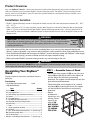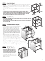
1
Service
This manual is to be used by qualified appliance
technicians only. Maytag does not assume any
responsibility for property damage or personal
injury for improper service procedures done by
an unqualified person.
This Base Manual covers general information
Refer to individual Technical Sheet
for information on specific models
This manual includes, but is
not limited to the following:
Maytag
MBV1976AAP
MBV1976AAB
MBS1976AAP
MBS1976AAB
Skybox
Personal Vending
Machine
16022983
March 2004
Important Information
Important Notices for Servicers and Consumers
Maytag will not be responsible for personal injury or property damage from improper service procedures. Pride and
workmanship go into every product to provide our customers with quality products. It is possible, however, that
during its lifetime a product may require service. Products should be serviced only by a qualified service technician
who is familiar with the safety procedures required in the repair and who is equipped with the proper tools, parts,
testing instruments and the appropriate service information. IT IS THE TECHNICIANS RESPONSIBILITY TO
REVIEW ALL APPROPRIATE SERVICE INFORMATION BEFORE BEGINNING REPAIRS.
!
WARNING
To avoid risk of severe personal injury or death, disconnect power before working/servicing on appliance to avoid
electrical shock.
To locate an authorized servicer, please consult your telephone book or the dealer from whom you purchased this
product. For further assistance, please contact:
Customer Service Support Center
CAIR Center
Web Site
Telephone Number
WWW.AMANA.COM ............................................... 1-800-843-0304
WWW.JENNAIR.COM ............................................ 1-800-536-6247
WWW.MAYTAG.COM ............................................. 1-800-688-9900
CAIR Center in Canada .......................................... 1-800-688-2002
Amana Canada Product .......................................... 1-866-587-2002
Recognize Safety Symbols, Words, and Labels
! DANGER
DANGER—Immediate hazards which WILL result in severe personal injury or death.
!
WARNING
WARNING—Hazards or unsafe practices which COULD result in severe personal injury or death.
!
CAUTION
CAUTION—Hazards or unsafe practices which COULD result in minor personal injury, product or property
damage.
2
16022983 Rev. 0
©2004 Maytag Appliances Company
Table of Contents
Important Information .................................................... 2
Troubleshooting
Disable Switches and Door Test ................................. 4
Bin Mechanism (Motors, Chute switches/doors and .....
Flipper door ................................................................ 5
Product Out (Home Sensor) and Anti-Jam .................. 6
Low Product Switches ............................................... 7
Dispense Test ............................................................ 7
Disassembly Procedures
Door Removal ............................................................ 8
Dispensing Assembly ................................................ 8
Temperature Control ................................................... 8
Ribbon Connector ...................................................... 8
Selection Buttons ...................................................... 9
Circulating Fan ........................................................... 9
Ballast and Light Bulb ................................................ 9
Wiring Diagram ............................................................ 10
Appendix A
Owner’s Manual ........ ........................................A-2
Appendix B
Skybase Assembly Manual ................................. B-2
©2004 Maytag Appliances Company
16022983 Rev. 0
3
Troubleshooting
!
WARNING
To avoid risk of electrical shock, personal injury, or death, disconnect electrical power source to unit, unless test
procedures require power to be connected. Discharge capacitor through a resistor before attempting to service.
Ensure all ground wires are connected before certifying unit as repaired and/or operational.
DISABLE SWITCHES and DOOR TEST
1. Apply power to the SKYBOX.
2. Verify that the door lights work properly, they can be
turned on and off.
Possible causes malfunction:
· Cable between the door and cabinet missing, not
wired correctly, or not plugged in fully.
· Light switch mounted upside-down.
· Incorrect wiring, wires crossed from each starter.
· Wire not pushed into socket or contamination on
wire.
· Starter or lamp missing or not installed properly.
· 120VAC wiring error.
· 120VAC not working at test outlet.
3. Move all DISABLE switches down (turn OFF the
bins).
4. Hold the MAIN DOOR switch closed, leaving the door
open.
5. All 4 LED on the door should be ON. If not, fail.
Possible causes:
· The LED that is OFF might have the DISABLE
switch assembled upside down, along with a bad
LOW PRODUCT switch circuit.
· If all of the LED flash slowly, there is a bad
connection between the door and the MAIN PCB.
(Loss of communications between the MAIN and
FPP PCBs).
· If the LED are all OFF, there is a bad connection
between the door and the MAIN PCB (no power).
· If the LED are all OFF, there is a bad connection
between the bin set and the MAIN PCB (ribbon
cable unplugged or bad).
· If the LED are all OFF, there is no power to the
MAIN PCB: verify that the 12VAC transformer is
connected to 120VAC between the bin set and the
MAIN PCB (ribbon cable unplugged). There are 2
LED on the MAIN PCB. The top LED indicates
communications TO the FPP (located in the door);
the bottom LED indicates communications FROM
the FPP.
· MAIN DOOR switch circuit not wired correctly:
wrong connection at switch or connector not
plugged into the MAIN PCB. When the MAIN
DOOR switch is first held closed, the LED should
flicker off for a very brief time.
4
6. Push SELECT pushbutton 1. Only LED1 should turn
off while the pushbutton is pushed. If not, fail.
· If multiple LED turn OFF, there is a problem with
the door electronics.
· If all 4 LED fast flash only while the SELECT
pushbutton is pushed, the FLIPPER DOOR is
open (or other problem in FLIPPER door sensor)
· If the wrong LED turns OFF, there is a problem
with the door electronics.
· If no LED turn OFF, there is a problem with the
door electronics.
· MAIN DOOR switch circuit not wired correctly:
wrong connection at switch or connector not
plugged into the MAIN PCB. When the MAIN
DOOR switch is first held closed, the LED should
flicker off for a very brief time.
7. Push SELECT pushbutton 2. Only LED 2 should turn
off while the pushbutton is pushed. If not, fail.
· If multiple LED turn OFF, there is a problem with
the door electronics.
· If all 4 LED fast flash only while the SELECT
pushbutton is pushed, the FLIPPER DOOR is
open (or other problem in FLIPPER door sensor)
· If the wrong LED turns OFF, there is a problem
with the door electronics.
· If no LED turn OFF, there is a problem with the
door electronics.
· MAIN DOOR switch circuit not wired correctly:
wrong connection at switch or connector not
plugged into the MAIN PCB. When the MAIN
DOOR switch is first held closed, the LED should
flicker off for a very brief time.
8. Push SELECT pushbutton 3. Only LED3 should turn
off while the pushbutton is pushed. If not, fail.
· If multiple LED turn OFF, there is a problem with
the door electronics.
· If all 4 LED fast flash only while the SELECT
pushbutton is pushed, the FLIPPER DOOR is
open (or other problem in FLIPPER door sensor).
· If the wrong LED turns OFF, there is a problem
with the door electronics.
· If no LED turn OFF, there is a problem with the
door electronics.
· MAIN DOOR switch circuit not wired correctly:
wrong connection at switch or connector not
plugged into the MAIN PCB. When the MAIN
DOOR switch is first held closed, the LED should
flicker off for a very brief time.
16022983 Rev. 0
©2004 Maytag Appliances Company
Troubleshooting
!
WARNING
To avoid risk of electrical shock, personal injury, or death, disconnect electrical power source to unit, unless test
procedures require power to be connected. Discharge capacitor through a resistor before attempting to service.
Ensure all ground wires are connected before certifying unit as repaired and/or operational.
9. Push SELECT pushbutton 4. Only LED 4 should turn
off while the pushbutton is pushed. If not, fail.
· If multiple LED turn OFF, there is a problem with
the door electronics.
· If all 4 LED fast flash only while the SELECT
pushbutton is pushed, the FLIPPER DOOR is
open (or other problem in FLIPPER door sensor)
· If the wrong LED turns OFF, there is a problem
with the door electronics.
· If no LED turn OFF, there is a problem with the
door electronics.
· MAIN DOOR switch circuit not wired correctly:
wrong connection at switch or connector not
plugged into the MAIN PCB.
BIN MECHANISM (MOTORS, CHUTE
switches/doors, and FLIPPER door)
1. Release the MAIN DOOR switch.
2. Move all DISABLE switches up (turn ON the bins).
3. Hold the MAIN DOOR switch closed, leaving the door
open.
4. Push SELECT pushbutton 1.
a.MOTOR 1 should turn at a normal speed and LED1
should be flashing slowly. If not, fail.
· The DISABLE switch circuit for that bin might be
bad.
· MAIN DOOR switch circuit not wired correctly:
wrong connection at switch or connector not
plugged into the MAIN PCB. When the MAIN
DOOR switch is first held closed, the LED should
flicker off for a very brief time.
· If the MOTOR runs slowly or not at all AND all 4
LED start flashing fast after 3 seconds, the
CHUTE sensor is broken on that bin (CHUTE
plate not returning to the proper resting position,
magnet missing or installed incorrectly, HOME/
CHUTE PCB not working or not plugged into the
CONNECTOR PCB).
b. Quickly trip the CHUTE plate #1. The motor
should stop or move very slowly. If not, fail.
· The CHUTE door sensor is not working properly.
Check for solder bridges and bad wiring on the
HOME/CHUTE PCB, CONNECTOR PCB, or
MAIN PCB.
c. Quickly trip the FLIPPER door. Verify that LED1
stops flashing slowly and stays ON. If not, fail.
· The FLIPPER door sensor is not working properly:
FLIPPER door not returning to the proper resting
position, magnet missing or installed incorrectly,
error in installation of FLIPPER PCB.
©2004 Maytag Appliances Company
5. Push SELECT pushbutton 2.
a. Motor 2 should turn at a normal speed and LED 2
should be flashing slowly. If not, fail.
· The DISABLE switch circuit for that bin might be
bad.
· MAIN DOOR switch circuit not wired correctly:
wrong connection at switch or connector not
plugged into the MAIN PCB. When the MAIN
DOOR switch is first held closed, the LED should
flicker off for a very brief time.
· If the MOTOR runs slowly or not at all AND all 4
LED start flashing fast after 3 seconds, the
CHUTE sensor is broken on that bin (CHUTE
plate not returning to the proper resting position,
magnet missing or installed incorrectly, HOME/
CHUTE PCB not working or not plugged into the
CONNECTOR PCB).
b. Quickly trip the CHUTE plate #2. The motor
should stop or move very slowly. If not, fail.
· The CHUTE door sensor is not working properly.
Check for solder bridges and bad wiring on the
HOME/CHUTE PCB, CONNECTOR PCB, or
MAIN PCB.
c. Quickly trip the FLIPPER door. Verify that LED 2
stops flashing slowly and stays ON. If not, fail.
· The FLIPPER door sensor is not working properly:
FLIPPER door not returning to the proper resting
position, magnet missing or installed incorrectly,
error in installation of FLIPPER PCB.
6. Push SELECT pushbutton 3.
a. Motor 3 should turn at a normal speed and LED 3
should be flashing slowly. If not, fail.
· The DISABLE switch circuit for that bin might be
bad.
· MAIN DOOR switch circuit not wired correctly:
wrong connection at switch or connector not
plugged into the MAIN PCB. When the MAIN
DOOR switch is first held closed, the LED should
flicker off for a very brief time.
· If the MOTOR runs slowly or not at all AND all 4
LED start flashing fast after 3 seconds, the
CHUTE sensor is broken on that bin (CHUTE
plate not returning to the proper resting position,
magnet missing or installed incorrectly, HOME/
CHUTE PCB not working or not plugged into the
CONNECTOR PCB).
b.Quickly trip the CHUTE plate #3. The motor should
stop or move very slowly. If not, fail.
· The CHUTE door sensor is not working properly.
Check for solder bridges and bad wiring on the
HOME/CHUTE PCB, CONNECTOR PCB, or
MAIN PCB.
16022983 Rev. 0
5
Troubleshooting
!
WARNING
To avoid risk of electrical shock, personal injury, or death, disconnect electrical power source to unit, unless test
procedures require power to be connected. Discharge capacitor through a resistor before attempting to service.
Ensure all ground wires are connected before certifying unit as repaired and/or operational.
c. Quickly trip the FLIPPER door. Verify that LED 3
· CONNECTOR PCB or ribbon cable problem
stops flashing slowly and stays ON. If not, fail.
4. Push SELECT pushbutton 2. Watch for proper anti· The FLIPPER door sensor is not working properly:
jam mechanism operation: the back plate must flip up
FLIPPER door not returning to the proper resting
then down while the motor is moving. If not, fail.
position, magnet missing or installed incorrectly,
· spring not working
error in installation of FLIPPER PCB.
· Cam mechanism not installed correctly.
7. Push SELECT pushbutton 4.
5. Allow MOTOR 2 to run until it stops (between 6 and
a. Motor 4 should turn at a normal speed and LED 4
10 seconds). The dispensing cup should now be at
should be flashing slowly. If not, fail.
the home position (open to accept product). If not,
· The DISABLE switch circuit for that bin might be
fail.
bad.
· The HOME sensor is not working on that bin:
· MAIN DOOR switch circuit not wired correctly:
magnet located on dispensing cup end missing or
wrong connection at switch or connector not
installed wrong, CHUTE-HOME PCB (SENMN)
plugged into the MAIN PCB. When the MAIN
broken, problem on CONNECTOR PCB (located
DOOR switch is first held closed, the LED should
on back of bin set), or ribbon cable problem.
flicker off for a very brief time.
· The HOME sensor input for that bin on the MAIN
· If the MOTOR runs slowly or not at all AND all 4
PCB is bad: short, missing resistor, etc.
LED start flashing fast after 3 seconds, the
· CONNECTOR PCB or ribbon cable problem.
CHUTE sensor is broken on that bin (CHUTE
6. Push SELECT pushbutton 3. Watch for proper antiplate not returning to the proper resting position,
jam mechanism operation: the back plate must flip up
magnet missing or installed incorrectly, HOME/
then down while the motor is moving. If not, fail.
CHUTE PCB not working or not plugged into the
· spring not working
CONNECTOR PCB).
· Cam mechanism not installed correctly.
b. Quickly trip the CHUTE plate #4. The motor
7. Allow MOTOR 3 to run until it stops (between 6 and
should stop or move very slowly. If not, fail.
10 seconds). The dispensing cup should now be at
· The CHUTE door sensor is not working properly.
the home position (open to accept product). If not,
Check for solder bridges and bad wiring on the
fail.
HOME/CHUTE PCB, CONNECTOR PCB, or
· The HOME sensor is not working on that bin:
MAIN PCB.
magnet located on dispensing cup end missing or
c. Quickly trip the FLIPPER door. Verify that LED4
installed wrong, CHUTE-HOME PCB (SENMN)
stops flashing slowly and stays ON. If not, fail.
broken, problem on CONNECTOR PCB (located
· The FLIPPER door sensor is not working properly:
on back of bin set), or ribbon cable problem.
FLIPPER door not returning to the proper resting
· The HOME sensor input for that bin on the MAIN
position, magnet missing or installed incorrectly,
PCB is bad: short, missing resistor, etc.
error in installation of FLIPPER PCB.
· CONNECTOR PCB or ribbon cable problem
PRODUCT OUT (HOME SENSOR) and ANTIJAM
1. Hold the MAIN DOOR switch closed, leaving the door
open.
2. Push SELECT pushbutton 1.
3. Allow MOTOR 1 to run until it stops (between 6 and
10 seconds). The dispensing cup should now be at
the home position (open to accept product). If not,
fail.
· The HOME sensor is not working on that bin:
magnet located on dispensing cup end missing or
installed wrong, CHUTE-HOME PCB (SENMN)
broken, problem on CONNECTOR PCB (located
on back of bin set), or ribbon cable problem.
· The HOME sensor input for that bin on the MAIN
PCB is bad: short, missing resistor, etc.
6
8. Push SELECT pushbutton 4. Watch for proper antijam mechanism operation: the back plate must flip up
then down while the motor is moving. If not, fail.
· spring not working
· Cam mechanism not installed correctly.
9. Allow MOTOR 4 to run until it stops (between 6 and
10 seconds). The dispensing cup should now be at
the home position (open to accept product). If not,
fail.
· The HOME sensor is not working on that bin:
magnet located on dispensing cup end missing or
installed wrong, CHUTE-HOME PCB (SENMN)
broken, problem on CONNECTOR PCB (located
on back of bin set), or ribbon cable problem.
· The HOME sensor input for that bin on the MAIN
PCB is bad: short, missing resistor, etc.
· CONNECTOR PCB or ribbon cable problem
16022983 Rev. 0
©2004 Maytag Appliances Company
Troubleshooting
!
WARNING
To avoid risk of electrical shock, personal injury, or death, disconnect electrical power source to unit, unless test
procedures require power to be connected. Discharge capacitor through a resistor before attempting to service.
Ensure all ground wires are connected before certifying unit as repaired and/or operational.
LOW PRODUCT SWITCHES
1. Release the MAIN DOOR switch.
2. Press the LOW PRODUCT plate for bin 1. Hold the
MAIN DOOR switch closed, leaving the door open.
Only LED1 should turn off. If not, fail.
· Mis-wired LOW PRODUCT harness and/or
switch.
· Mis-aligned LOW PRODUCT plate.
· The LOW PRODUCT input for that switch on the
MAIN PCB is bad: short, missing resistor, etc.
· CONNECTOR PCB or ribbon cable problem.
3. Release the MAIN DOOR switch.
4. Press the LOW PRODUCT plate for bin 2. Hold the
MAIN DOOR switch closed, leaving the door open.
Only LED2 should turn off. If not, fail.
· Mis-wired LOW PRODUCT harness and/or
switch.
· Mis-aligned LOW PRODUCT plate.
· The LOW PRODUCT input for that switch on the
MAIN PCB is bad: short, missing resistor, etc.
· CONNECTOR PCB or ribbon cable problem.
5. Release the MAIN DOOR switch.
· Mis-wired LOW PRODUCT harness and/or
switch.
· Mis-aligned LOW PRODUCT plate.
· The LOW PRODUCT input for that switch on the
MAIN PCB is bad: short, missing resistor, etc.
· CONNECTOR PCB or ribbon cable problem
6. Press the LOW PRODUCT plate for bin 3. Hold the
MAIN DOOR switch closed, leaving the door open.
Only LED 3 should turn off. If not, fail.
7. Release the MAIN DOOR switch.
8. Press the LOW PRODUCT plate for bin 4. Hold the
MAIN DOOR switch closed, leaving the door open.
Only LED 4 should turn off. If not, fail.
· Mis-wired LOW PRODUCT harness and/or
switch.
· Mis-aligned LOW PRODUCT plate.
· The LOW PRODUCT input for that switch on the
MAIN PCB is bad: short, missing resistor, etc.
· CONNECTOR PCB or ribbon cable problem.
DISPENSE TEST
· Place 1 product into each of the 4 bins. Close the
MAIN DOOR. Verify that each bin dispenses the
product properly through the FLIPPER door. If
not, fail.
TEST COMPLETE
©2004 Maytag Appliances Company
16022983 Rev. 0
7
Disassembly Procedures
!
WARNING
To avoid risk of electrical shock, personal injury, or death, disconnect electrical power source to unit, unless test
procedures require power to be connected. Discharge capacitor through a resistor before attempting to service.
Ensure all ground wires are connected before certifying unit as repaired and/or operational.
Door Removal
1. Make sure the main unit is OFF and the powercord is
unplugged.
2. Unplug the door wire harness from the lower right
corner of the door and the lower left corner of the
personal beverage vendor.
3. Open the door wider than a 90° angle.
4. Lift the door up, releasing the door hinges from the
hinge posts.
Dispensing Assembly
1. Remove Door (see Door removal procedure)
2. Remove Sling assembly by unhooking two hooks
from sling at top of chute opening and removing from
velcro from left side of cabinet.
3. Remove screws holding dispenser assembly in place,
5 screws on front of dispensing assembly and 4 on
left hand side of dispenser.
4. Slide dispenser assembly out and unplug ribbon
connector from dispenser assembly.
8
Temperature Control
1. Remove single screw at bottom of temperature
control.
2. Slide down temperature control to expose wiring and
sensing bulb.
3. Disconnect wires from temperature control. Note
location of wires when removing temperature control.
4. Slide sensing capilary tube out of sleeve while
removing temperature control.
5. Reverse procedure to reassemble.
Ribbon Connector
1. Remove dispenser assembly (see dispenser
assembly removal).
2. Unplug ribbon connector from dispenser assembly.
3. Remove plug seal from inside back of cabinet holding
connector in place.
4. Remove machine compartment screws from back
side of machine compartment.Remove machine
compartment cover.
5. Remove cover from main board by removing screws.
6. Unplug ribbon connector from board and slide it
through hole in cabinet.
7. Reverse procedure to reassemble.
16022983 Rev. 0
©2004 Maytag Appliances Company
Disassembly Procedures
!
WARNING
To avoid risk of electrical shock, personal injury, or death, disconnect electrical power source to unit, unless test
procedures require power to be connected. Discharge capacitor through a resistor before attempting to service.
Ensure all ground wires are connected before certifying unit as repaired and/or operational.
Selection Buttons
1. Grasp the bottom of the selection button and pull
toward you.
2. While the selection button is pulled out, pull down on
the selection button firmly to release selection button
from cabinet.
3. Reverse procedure to reassemble.
Ballast and Light Bulb
1. Remove top cover from cabinet by lifting it off of unit.
2. Remove plexiglass cover by lifting it from the slot at
the front of the cabinet to expose ballast or light bulb.
3. Reverse procedure to reassemble.
Circulating Fan
1. Remove dispenser assembly (see dispenser
assembly removal).
2. Remove circulating fan screws and unplug from
cabinet PCB.
3. Remove circulating fan.
Note: Circulating fan must be installed so the airflow
draws air from the dispenser assembly.
4. Reverse procedure to reassemble.
©2004 Maytag Appliances Company
16022983
Rev. 0
9
Wiring Diagram and Schematic
!
WARNING
To avoid risk of electrical shock, personal injury, or death, disconnect power to freezer before servicing, unless
testing requires it. Wires removed during disassembly must be replaced on proper terminals to insure correct
grounding and polarization.
CAUTION
EARTH GROUND
NEUTRAL
LINE
High Voltage
MOTOR+3
MOTOR+4
MOTORCOMMON
/MAIN_CLOSED_BIN
/DISABLE4
/DISABLE3
/DISABLE2
/DISABLE1
/LOW1
/LOW2
/LOW3
/LOW4
!
BLACK
WHITE
GREEN
LINE
NEUTRAL
EARTH GROUND
/HOME1
/CHUTE1
+5V_SWITCHED
/HOME2
/CHUTE2
COMMON
/HOME3
/CHUTE3
/HOME4
/CHUTE4
COMMON
MOTOR+1
MOTOR+2
/HOME1
/ CHUTE1
+5V_SWITCHED
/HOME2
/ CHUTE2
COMMON
/HOME3
/ CHUTE3
/HOME4
/ CHUTE4
COMMON
MOTOR+1
MOTOR+2
REFRIGERATOR
CHAMBER
MOTOR+3
MOTOR+4
MOTORCOMMON
/MAI N_CLOSED_BIN
/DISABLE4
/DISABLE3
/DISABLE2
/DISABLE1
/LOW1
/LOW2
/LOW3
/LOW4
MBV1976AAP
MBV1976AAB
10
16022983 Rev. 0
©2004 Maytag Appliances Company
Appendix A
A-1
®
SkyBox™ by Maytag™
Personal Beverage Vendor
Model # MBV1976AA
The bragging rights are all yours. Congratulations on your purchase
of the SkyBox™ by Maytag™ personal beverage vendor. It’s time to
assemble your SkyBox™ personal beverage vendor, stock it with your
favorite cans or bottles, and give your buddies a call. Don’t be
surprised if they spend more time checking out the SkyBox™
personal beverage vendor than they do the instant replays!
Table of Contents
Important Safety Instructions ........................................ 1-2
Product Overview.................................................................... 3
Assembly ............................................................................... 4-9
Operation.......................................................................... 10-11
Features ................................................................................... 12
Maintenance .......................................................................... 13
Before You Call For Service.............................................. 14
Warranty/Customer Service ............................................. 15
Form No. C/02/10/04
Part No. 381-90-000100
www.skyboxbymaytag.com
Important Safety Instructions
What You Need to Know About
Safety Instructions
DANGER
Warning and Important Safety Instructions appearing in
this manual are not meant to cover all possible
conditions and situations that may occur. Common
sense, caution and care must be exercised when
installing, maintaining or operating this appliance.
Child entrapment and suffocation are not problems
of the past. Junked or abandoned refrigeration
products are still dangerous…even if they will sit for
“just a few days”. If you are discarding an old
SkyBox™ product, please follow the instructions
below to help prevent accidents.
Always contact your dealer, distributor, service agent or
manufacturer about problems or conditions you do not
understand.
• Remove the SkyBox™
personal beverage vendor
door (see page 13).
Recognize Safety Symbols, Words,
Labels
• Leave the storage bins in
place so that children may not
easily climb inside the unit.
DANGER
DANGER – Immediate hazards which WILL result
in severe personal injury or death.
WARNING
WARNING – Hazards or unsafe practices which
COULD result in severe personal injury or death.
CAUTION
CAUTION – Hazards or unsafe practices which COULD
result in minor personal injury or property damage.
WARNING
Electrical Grounding Instructions – This appliance
is equipped with a (3-prong) grounding plug for
your protection against shock hazard. It should be
plugged directly into a properly grounded
receptacle. Do not cut or remove the grounding
prong from this plug. If the plug fails to fit into an
existing outlet, contact a qualified electrician to
update the outlet.
Power supply
cord with
3-prong
grounding plug
Grounding type
wall receptacle
Your SkyBox™ personal beverage vendor should not,
under any circumstances, be operated when not
properly grounded.
1
Important Safety Instructions
Important Safeguards
WARNING
To reduce risk of fire, electric shock, serious
injury or death when using your refrigerated unit
and stand, follow these basic precautions,
including the following:
1. Read all instructions.
2. To prevent injury, children should not climb, hang
or stand on any part of this refrigerated unit or
stand.
3. Use the refrigerated unit and stand only for their
intended purpose.
4. Observe all local codes and ordinances.
5. To prevent the possibility of hazard due to
electrical shock, never plug the refrigerated unit
in to a receptacle that has not been grounded
adequately and in accordance with the local and
national electrical codes. See warning and the
grounding instructions that follow.
6. Do not use a 2-prong adapter, extension cord or
power strip.
7. Disconnect the power cord to the refrigerated unit
before loading cans or bottles into it, cleaning,
servicing or replacing a light bulb. Disconnect
power cord by grasping the plug, not the cord.
8. The refrigerated unit power cord should be
immediately repaired or replaced if it becomes
frayed or damaged or if the plug will not fit
securely into the electrical outlet.
9. To prevent fire hazard, your refrigerated unit
should not be operated in the presence of
gasoline or other flammable vapors and liquids.
10. Keep your SkyBox™ personal beverage vendor in
good condition. Bumping or dropping the
personal beverage vendor and/or SkyBase™ stand
can damage them or cause them to malfunction
or leak. If damage occurs, contact a qualified
service technician for repair.
11. Always read and follow manufacturer’s installation
and operation instructions for items being stored
in refrigerated unit. Load cans or bottles into the
personal beverage vendor as described in this
guide.
12. Do not lift or move the personal beverage vendor
and/or SkyBase™ stand when it is loaded with
beverages or when the door is open.
13. The SkyBox™ personal beverage vendor is not
designed to dispense food items other than the
designated beverage containers outlined within
this guide.
14. Do not kick, pound, or push on the personal
beverage vendor and/or stand, as this may cause
the unit to tip or may damage the refrigeration
system.
15. The SkyBox™ personal beverage vendor is
designed to hold beverage containers within the
designated beverage shelf on top of the main
unit. Do not place additional items on top of the
unit.
16. Do not attempt to place fingers, hands or arms
through the beverage dispenser opening. If a
beverage jams in the SkyBox™ personal beverage
vendor, clear the jam using the instructions
provided on page 13 of this guide.
SAVE THESE INSTRUCTIONS FOR FUTURE REFERENCE
2
Product Overview
SkyBox™ by Maytag Personal
Beverage Vendor – Refrigerated unit
with front door. Opens for easy access to
four beverage storage bins. Fully stocked,
the unit will hold 64 12-ounce cans or
32 12-ounce bottles.
Front Display Graphic –
Packaged with the SkyBox™
personal beverage vendor.
Beverage Cards - Your
SkyBox™ personal beverage
vendor comes with a set
of commonly requested
beverage cards that can be
used to label the beverage
selection buttons. To
purchase additional
beverage cards, visit
www.skyboxbymaytag.com.
SkyBase™ Stand (optional) – A sturdy, level stand that
is able to support approximately 200 pounds of weight
and will safely accommodate your fully stocked personal
beverage vendor. SkyBox™ personal beverage vendor
securely mounts to the SkyBase™ stand. To purchase, visit
your local retailer or www.skyboxbymaytag.com.
3
Display Panels – Panels
slide into the front and
sides of the main unit.
Your SkyBox™ personal
beverage vendor comes with
a standard front panel. To
purchase customized, interchangeable front and side
panels that feature your
favorite sports team, visit
www.skyboxbymaytag.com.
Assembly
Dimensions
WARNING
Once assembled, the Skybox™ (main unit mounted on
stand) has the following dimensions:
• IMPORTANT: For safety, the unit should be
displayed in a secure, level area, with the back of
the unit securely against a wall, with 3" (77 mm) of
clearance. The wall installation is to prevent
anyone, including children, from getting behind
the unit and tipping it over, causing personal
injury.
33.5"
(851 mm)
Important
Wall
Installation
58.5"
(1486 mm)
25"
(635 mm)
22.12"
(562 mm)
25"
(635 mm)
Installation Location
• SkyBox™ personal beverage vendor is designed for
indoor use only with room temperatures between
50° – 80° F (10° – 27° C).
• Use caution when installing the unit on vinyl or
hardwood floors so as not to mark or otherwise
damage the flooring. A piece of plywood, a rug or
other material should be used to protect the floor
while positioning the unit.
• Once assembled and loaded with beverages, the
SkyBox™ personal beverage vendor with SkyBase™
stand weighs up to 300 pounds (136 kg), so select a
location that will not require frequent moving.
• Moving the loaded SkyBox™ personal beverage
vendor may cause damage to the unit.
WARNING
To avoid serious risk of injury, DO NOT lift or move
the SkyBox™ personal beverage vendor and/or
SkyBase™ stand when loaded with beverages or
when the door is open.
• Allow a minimum of 5" (127 mm) clearance from the
door hinges to a side wall to allow the door to swing
open. Allow 3" (77 mm) of clearance behind the
SkyBox™ personal beverage vendor and 1" (26 mm)
clearance on all other sides for ease of installation.
Additional space is required above the main unit to
change the front or side display panels.
WARNING
To avoid injury, follow these important instructions
when installing the SkyBox™ personal beverage
vendor on a countertop.
Make sure the vendor is placed far back on the
countertop -- at least 6 inches (15 cm) from the
counter front edge to the edge of the vendor door.
4
Assembly
STEP 2 – Level the Stand
Stand Assembly
K
Carefully unpack the stand parts (see below) from the
packaging.
Tools Needed:
• #2 phillips head screw driver
• Adjustable Wrench
Parts
A
B
C
D
E
F
G
H
I
J
K
L
M
N
FF
M
• Level
Quantity
End Frame.......................................................................................................2
Long Support Rail.......................................................................................4
Rear Leveling Legs (attached to end frames)..............................2
Shelves..............................................................................................................2
Pan-Head Screws.....................................................................................24
Left Side Panel (with hinge holes) .....................................................1
Right Side Panel (with no hinge holes)...........................................1
Back Panel......................................................................................................1
Door....................................................................................................................1
Hinges (attached to the door)..............................................................2
Front Foot.........................................................................................................2
M5 x 16 Hex-Phillips Head Cap Screw - 5⁄8” (16mm) long....6
Front Foot Leveling Head........................................................................2
Flat Head Screws.........................................................................................6
M5 x 20 Hex-Phillips Head Cap Screw - 3⁄4” (20mm) long....2
STEP 1 – Assemble Frame of Stand
A
C
Lx 3
K/M
Lx 3
• Attach the two front feet (K) to the bottom of the
two corner posts using three M5 x 16, 5⁄8 ” (16 mm)
long, Hex-Phillips head cap screws (L) for each foot.
NOTE: The threaded bolt on the front foot must
extend outward away from the frame (see figure).
• Attach the front foot leveling head (M) to the
threaded bolt on each front foot (K).
• Carefully place the partially assembled stand on the
floor where it will be displayed. Adjust the front foot
leveling heads (M) down so that the front foot roller
is just off the floor. Using a level and an adjustable
wrench, adjust the two rear leveling legs (C) so the
unit sits squarely on the floor.
STEP 3 – Install Shelves
E
B
D
D
• Connect one long support rail (B) to one of the end
frames (A) by inserting the tabs on the support rail
into the slots of the end frame and pressing
downward. The support rails will temporarily lock into
place when pressed downward.
• Connect the other end of support rail to a second
end frame (A) by inserting the tabs on the support
rail into the slots of the end frame and pressing
downward.
• Repeat procedure for remaining 3 rails, creating a
basic frame for the cabinet. DO NOT INSTALL ANY
SCREWS (E) DURING THIS STEP!
5
• Place bottom shelf (D) on top of lower support rails.
Align screw holes and install four pan-head screws
(E).
• Repeat procedure for center shelf (D) which mounts
on the four tabs welded to the end frame.
Assembly
STEP 4 – Assemble Exterior Panels
E
G
F
STEP 5 – Attach Door to
SkyBase™ Stand
F
E
E
N/J
I
• Lower the top lip of the left side panel (F) over the
top of end frame, aligning screw holes in side panel
with holes in the corner post. Make sure panel is
positioned to accommodate hinges for door on front
left side. Attach panel by installing three pan-head
screws (E) down the front of the unit and two panhead screws (E) along the top rail.
• Position the right side panel (G) over frame of
cabinet, aligning screw holes in side panel with holes
in corner post. Attach panel by installing
three pan-head screws (E) down the front of each
side panel and two pan-head screws (E) along the
top rail.
• Position door (I) on the front of the stand by aligning
screw holes in the hinges (J) with hinge holes in the
left side panel on the front of the stand.
• Attach door hinges (J) to the left side panel (F)
using three flat-head screws (N) in each hinge.
G
H
E
F
• Place back panel (H) over frame and side panels by
aligning screw holes on the back of the unit. Attach
back panel using six pan-head screws (E). During
this process, the screws will also secure the back of
the left and right side panels.
6
Assembly
SkyBox™ Personal Beverage
Vendor Top and Door
Assembly (Select Packaging Only)
Carefully unpack the SkyBox™ personal beverage
vendor from the packaging.
If needed, follow these instructions for attaching the
door to the main unit of your SkyBox™ personal
beverage vendor.
Parts
Quantity
Top Cover .........................................1
Main Unit .........................................1
Door ...................................................1
Door Wire Harness.......................1
STEP 2 – Attach Door
• Align hinges of door to hinge
posts on the main unit. Hold
door at an angle (greater
than 90°) from the main unit
opening. (Note: For your safety,
the door will not attach or
detach at a 90° angle.)
• Slide hinges down onto hinge
posts. Door will slide on easily.
DO NOT FORCE.
STEP 3 – Attach Door Wire Harness
STEP 1 – Attach Top Cover
• Slide hooks at front of top panel into slots at front of
main unit.
• Press top cover down in back so 3 tabs snap
securely into place onto back of main unit.
WARNING
Confirm that the electrical cord on the SkyBox™
personal beverage vendor IS NOT plugged into an
electrical outlet before attaching the door wire harness.
Top
Cover
Main
Unit
Wire
Harness
• Attach one end of door wire harness to plug-in on
lower left corner of main unit opening, aligning plug
with small tab facing up to fit plug-in. Note: plug will
only fit one direction. DO NOT FORCE.
• Attach other end of door wire harness to plug-in on
lower right corner of door, aligning plug with small
tab facing up to fit plug-in. Note: plug will only fit
one direction. DO NOT FORCE.
7
Assembly
SkyBox™ Personal Beverage
Vendor Main Assembly
Tools Needed:
• Phillips head screw driver
Parts
AA
BB
CC
DD
EE
FF
Graphic Access Cover ...........................1
Front Display Graphic ............................1
Clear Panel .................................................1
Light bulbs..................................................2
Beverage Cards ........................................4
Connecting Bolts: M5 x 20 ...................
Hex-Phillips Head Cap ............................
Screws - 3⁄4 ” (20 mm) long...................2
• Make sure SkyBox™ personal
beverage vendor is OFF and
the power cord is unplugged.
• Flip the graphic access cover (AA) back down into
place.
STEP 2 – Install Beverage Cards
Quantity
STEP 1 – Install Light Bulbs
• Reinsert the screw.
EE
CC
• Bend beverage cards (EE) back at score line, so
small fold is away from printed side.
• Gently pull out the bottom edge of the beverage
buttons toward you and slide the beverage cards
(EE) into the buttons, sandwiching them in the small
slit between the clear plastic.
AA
• Flip up the graphic access
cover (AA), exposing a screw
and the top edge of the front
graphics panel.
STEP 3 – Attach SkyBox™ Personal
Beverage Vendor to
SkyBase™ Stand
• Remove the screw.
• Slide the front display graphic
(BB-see page 3) up and out
of the personal beverage
vendor.
• Lift the clear panel (CC) up
and out of the unit, exposing
the sockets for the light bulbs.
DD
FF
• Place the SkyBox™ personal beverage vendor on the
SkyBase™ stand.
• Remove the two 18" fluorescent light bulbs, type
F15T8 15 watt (DD) from their packaging and install
by sliding them into the light sockets and rotating
away from you until they click into place.
• Replace the clear panel (CC) and slide the front
display graphic (BB) back into place in front of the
clear panel, behind the lower edge of the frame
opening.
• IMPORTANT: Line up holes on bottom of SkyBox™
personal beverage vendor with holes in top of
SkyBase™ stand. Carefully thread a connecting bolt
(FF–see illustration) into each hole up through the
inside of the stand and into the hole in the SkyBox™
personal beverage vendor. Secure firmly.
8
Assembly
Changing SkyBox™
Display Graphics
STEP 2 – Change Front Display Graphic
Your SkyBox™ personal beverage vendor comes with a
standard front panel. To purchase customized,
interchangeable front and side display graphics visit
your local retailer or www.skyboxbymaytag.com.
• Make sure SkyBox™ personal beverage vendor is
OFF and the power cord is unplugged.
STEP 1 – Install Side Display Graphics
• Flip up the graphic access cover, exposing a screw
and the top edge of the front display graphic.
• Remove the screw.
• Remove top of SkyBox™ personal beverage vendor
by lifting up the tabs at rear of top panel. Pull top
cover back slightly to remove from frame. Set aside.
• Gently press hands onto front display graphic within
frame and slide it up and out of the personal
beverage vendor.
• Slide the new customized display graphic into the
frame, making sure the panel slides behind the lower
edge of the frame opening.
• Flip the display graphic access cover back down into
place.
• Slide one customized display graphic into each side
of the SkyBox™ personal beverage vendor, tucking
the panels in at the bottom within the grooves in the
frame.
• Replace the top cover by sliding hooks into front and
then pressing down tabs at the rear.
9
Operation
1. ASSEMBLE the stand and personal beverage
vendor (see pages 4-9).
2. LOAD personal beverage vendor with beverages
(see below).
3. PLUG UNIT IN to grounded 3-prong outlet.
4. TURN LIGHTS on by pressing switch on the right
side of the personal beverage vendor above the
keyhole.
5. SET THERMOSTAT dial found inside the main unit
in the upper left hand corner by turning dial
clockwise to desired temperature. The further you
turn the dial, the colder the temperature.
6. ALLOW TO COOL. After the personal beverage
vendor is initially plugged in, it will take
approximately 3-4 hours to chill your beverages.
7. SERVE yourself and your guests by pressing the
corresponding button for the beverage of your
choice.
Loading SkyBox™ Personal
Beverage Vendor With
Beverages
Your SkyBox™ personal beverage vendor is designed to
hold a total of approximately 64 cans, 32 bottles or a
combination of both. When stocking your unit, keep
the following points in mind:
Place your
beverage container
here to check size.
3"
(76 mm)
Maximum
2.35" (60 mm)
Minimum
Child Lock-Out
The SkyBox™ personal
beverage vendor comes
equipped with a Child LockOut feature. Simply open the
door to the personal
beverage vendor and lock
each storage bin (or only
those bins you wish to lock).
To lock, slide down the small
switch at the right end of the
corresponding storage bin. To unlock the storage bin,
slide the switch at the right end of that bin up.
IMPORTANT: The Child Lock-Out controls which
beverages are dispensed from the SkyBox™ personal
beverage vendor. However, to completely secure
access to beverages, be sure to use the key provided
to LOCK THE DOOR to the main unit.
• Beverage containers should be a
minimum of 2.35" (60 mm) and a
maximum of 3" (76 mm) in
diameter.
9.75"
(247 mm)
Maximum
• Beverage containers should be
round, since the dispensing system
works in combination with gravity,
and the containers need to be able to roll.
• Beverage containers should be no taller than the
equivalent of 2 standard soda cans stacked on top of
each other or 9.75” (247 mm).
Loading Tips:
• For smooth operation, avoid mixing cans and
bottles within a single storage bin.
• For beverages that are known
to be highly carbonated
(such as high foaming
beer), load
beverage
containers into
the lower 2 bins to
limit fizzing and spillage.
10
Operation
Beverage Options
The following beverage containers will fit in the main
unit of your SkyBox™ personal beverage vendor.
12-ounce aluminum beverage cans
12-ounce glass beverage bottles
12-ounce plastic beer bottles
20-ounce plastic water and soda bottles
Each storage bin within the main unit is equipped to
dispense bottles or cans.
Highly Carbonated Beverages: Stock lower storage
bins with highly carbonated beverages and make sure
they are chilled before dispensing. To avoid overflow
spills when experimenting with new, highly carbonated
beverages, wait 10-15 seconds before opening
dispensed beverage containers, and open carefully
over the sink.
Capacity: The top storage bin will hold 10 cans or
5 bottles. The bottom 3 storage bins will each hold 18
cans or 9 bottles.
Important Steps For Loading
Please follow loading instructions. Improper loading
may cause the “low-indicator light” above the beverage
buttons to illuminate prematurely.
1. Make sure the main unit is OFF and the power
cord is unplugged.
2. Open the front door to the main unit, exposing the
four storage bins.
3. When loading the beverage containers, be sure to
load with the TOPS TOWARD THE FRONT
(i.e. long-neck bottles with necks towards the
front).
11
4. IMPORTANT - Begin loading the left end of the
storage bin, placing one beverage container on its
side all the way to the back with the top facing
forward. If loading cans, push the first one all the
way to the back and then place one directly in
front.
5. Next, move one space to the right and place
another beverage container all the way to the back.
If stocking cans, add another directly in front. (See
illustration at bottom of page.) Continue until the
storage bin is filled. Repeat with remaining storage
bins.
6. Once the bins are filled, close the door, plug the
power cord into a grounded outlet.
7. Insert corresponding
beverage cards into the
beverage selection
buttons by carefully
pulling the bottom edge
of the buttons forward
and up and slipping in
the cards. The far left button corresponds to the
top storage bin. The next button to the right
matches the storage bin that is second from the
top, etc.
Features
2
12
5
5
9
6,7
4
1
13
3
1. Personal Beverage Vendor/Main Unit – The
main refrigerated unit is equipped with four
storage bins that combine to store up to 64 cans or
32 bottles. Available in either Pitch Black or Grid
Iron Platinum, the main unit is designed to
complement your customized display panels.
2. Beverage Shelf – The top front area on the
personal beverage vendor is designed to hold
beverage containers.
3. SkyBase™ Stand – Your SkyBase™ stand,
available in Pitch Black or Grid Iron Platinum, safely
supports your fully stocked personal beverage
vendor. It also offers additional room temperature
storage space and includes a shelf.
4. Power Cord – The power cord is designed to
operate on a normal 120VAC, 15 amp, 60 cycle line.
For your safety, it is equipped with a grounded,
3-prong plug.
5. Customized Display Graphics – Show off your
true colors with interchangeable front and side
graphics. Unlike your old fridge, the front graphic
illuminates just like commercial vending machines.
As each new sports season begins, change out
your graphics with a new logo. To order new
graphics, visit your local retailer or
www.skyboxbymaytag.com.
6. Beverage Selection Buttons – Insert beverage
cards for your favorite beverages, and press the
buttons to serve yourself and your guests. Unlike
industrial vending machines, the SkyBox™ personal
beverage vendor operates without coins or dollar bills.
7. Interchangeable Beverage Cards – Your
SkyBox™ personal beverage vendor is packaged
with 20 beverage cards featuring the top
beverages. The beverage buttons carefully pull
forward and up, allowing you to insert any card you
choose. Order additional brands or replacement
cards online at www.skyboxbymaytag.com.
8. Auto-off Sensor – For safety purposes, any time
the door to the refrigerated main unit is opened,
the unit will not vend.
9. Low-Indicator Light – Avoid being caught with
warm drinks. When your beverage bins get low
(3 bottles or 6 cans remaining), the low-indicator
light will illuminate above the beverage button to
signify that it’s time to restock.
10. Anti-Fizzing – The specially designed SkyBox™
personal beverage vendor beverage dispenser
smoothly delivers your beverages with little shaking
or jostling. That means less foaming when you
open your cans or bottles. Be aware that warm
beverages are more likely to fizz. Cool beverages
prior to dispensing. Refer to pages 10-11 for tips
on loading highly carbonated beverages.
11. Jam Detector – In the unlikely event that your
unit experiences a jam, the low-indicator lights will
flash to identify the problem. Turn the unit off and
unplug the power cord before opening the unit to
inspect for jams. Refer to page 13 for proper steps
to prevent jams.
12. Child Lock-Out – For the safety of children or to
control curious pets, your SkyBox™ personal
beverage vendor is equipped with a child lock-out
feature. Lock individual beverage options or lock
them all with an easy flip of a switch. See page 10
for details.
13. Main Unit Door Keylock – Store your beverages
securely by locking the door to your main unit using
the keyhole on the right side of the main unit.
12
Maintenance
Cleaning
Consider the following checklist.
WARNING
To avoid electrical shock, which can cause severe
personal injury or death, unplug the refrigerated
personal beverage vendor unit before cleaning.
• Have you loaded the beverage containers on their
sides all the way to the back with the tops facing
forward?
• Are your beverage containers no more than 3" in
diameter?
The modular design of your SkyBox™ personal
beverage vendor allows for easy cleaning. Most spills
can be cleaned up with a damp cloth or sponge. If
using a household cleaner, choose a mild, nonabrasive cleaner that will not scratch or dull the
surface of your unit. Do not allow beverage spills to
stand; clean up right away.
• Are you using cans or bottles of odd shapes or
sizes? If so, loading your SkyBox™ personal beverage
vendor with a single row of that product may help to
reduce jams.
To avoid spills, do not store previously opened or
partially consumed bottles/cans in the SkyBox™
personal beverage vendor.
• Has the personal beverage vendor fully cooled
down? Some jams are more likely to occur when the
vendor is first plugged in and has not fully cooled.
Removing The Door
Replacing Display Panel Light
Bulbs
1. Make sure the main unit is OFF and the power
cord is unplugged.
2. Unplug the door wire harness from the lower right
corner of the door and the lower left corner of the
personal beverage vendor.
• Is your personal beverage vendor crowded beyond its
capacity?
1. Make sure SkyBox™ personal beverage vendor is
OFF and the power cord is unplugged.
2. Flip up the graphic access cover, exposing a screw
and the top edge of the front display panel.
3. Open the door wider than a 90° angle.
3. Remove the screw.
4. Lift the door up, releasing the door hinges from the
hinge posts.
4. Slide the front display graphic up and out of the
personal beverage vendor.
Clearing Jams
5. Lift the clear panel up and out of the unit, exposing
the sockets for the light bulbs.
If a jam occurs, the low-indicator lights will flash to
indicate the problem. If a single light is flashing, this
indicates that the jam is located within the corresponding storage bin. If all lights are flashing, this
indicates the jam is most likely located in the dispensing pathway. Most jams result from improper loading,
so please refer to pages 10-11 for proper loading
instructions.
6. Remove bulbs by rotating the bulbs toward you.
To clear a jam open the SkyBox™ personal beverage
vendor door and inspect the dispensing pathway and
the storage bins. Remove or readjust the location of
the beverage containers.
7. Install new 18" fluorescent bulbs type F15T8, 15
watt by sliding them into the light sockets and
rotating the bulbs away from you until they click
into place.
Opening the door to clear the jam will eliminate the
blinking lights.
8. Replace the clear panel and slide the front display
graphic back into place in front of the clear panel,
behind the lower edge of the frame opening.
9. Reinsert the screw.
10. Flip the graphic access cover back down into place.
13
Before You Call For Service
PROBLEM
POSSIBLE SOLUTION
The low-indicator lights are on, but the
main unit is not low on beverages.
The main unit may be improperly loaded, which will cause
the low-indicator light to illuminate prematurely. For
example, if cans or bottles are not pushed all the way to
the back of the unit, this will cause the low-indicator light
to illuminate. Refer to proper loading instructions on
pages 10-11.
The low-indicator lights are flashing rapidly.
The main unit may be jammed, and the light is indicating
the problem. Refer to page 13 to clear the jam. To eliminate
the blinking lights, simply open and close the personal
beverage vendor door.
No beverages dispense when beverage
button is pushed.
Make sure unit is loaded with beverages. Beverages
should be loaded on their sides, all the way to the back,
with the tops facing towards the front.
The Child Lock-out feature may be activated. Open the
door to the main unit and make sure the lock at the right
end of the each storage bin is open (upright position).
Check for possible jams. See page 13.
NEVER kick, pound or push on the beverage center to
attempt to dispense beverages.
Beverage center is not cooling.
Make sure you are using the main unit rather than the
stand for refrigerated storage. The stand is not refrigerated.
Check to see if the unit is plugged in to a grounded,
3-prong outlet.
Check thermostat dial in upper lefthand corner of SkyBox™
personal beverage vendor, and turn clockwise all the way
to the right.
Beverage container jams.
See page 13 for suggestions.
14
Warranty/Customer Service
All SkyBox™ by Maytag™ personal beverage vendors
are warranted for 1 year from date of purchase
against defects in material and workmanship. During
this period, any Maytag product that, upon
inspection by Maytag, is proved defective will be
repaired or replaced, at Maytag’s option, without
charge to the customer.
This warranty does not apply to any defect arising
from a buyer’s or user’s misuse of the product,
negligence, failure to follow Maytag’s instructions,
use on current or voltage other than that stamped
on the product, or alteration or repair not authorized
by Maytag. If a replacement product is sent, it will
carry the remaining warranty of the original
product. Repair or disassembly by anyone other than
a Maytag authorized service center will void the
warranty.
THE WARRANTIES SET FORTH HEREIN ARE
EXCLUSIVE AND NO OTHER WARRANTIES,
EXPRESS OR IMPLIED, INCLUDING BUT NOT
LIMITED TO ANY WARRANTY OF
MERCHANTABILITY OR FITNESS FOR A
PARTICULAR PURPOSE OR USE, ARE MADE BY
MAYTAG OR ARE AUTHORIZED TO BE MADE
WITH RESPECT TO THE PRODUCT.
What Is Not Covered By This
Warranty:
1. Warranty is void if the original serial numbers have
been removed, altered or cannot be readily
determined.
2. Products purchased for commercial or industrial
use.
3. Consequential or incidental damages sustained by
any person as a result of any breach of these
warranties. Some states do not allow the exclusion
or limitation of consequential or incidental
damages, so the above exclusion may not apply.
Contacting Customer Service:
1. Call MAYTAG Customer Service at 1-877-366-5426
U.S.A. or 1-800-688-2002 Canada. They may be
able to assist you with troubleshooting product
difficulties. U.S. Customers using TTY for deaf,
hearing impaired or speech impaired, call
1-800-688-2080 (Mon.-Fri., 8 a.m.-8 p.m. Eastern
Time).
2. Write to MAYTAG, Attn. CAIR® Center,
P.O. Box 2370, Cleveland, TN 37320-2370.
When writing or calling about a service problem,
please include the following information:
a. Your name, address and telephone number;
b. Model and serial number of the product (the
model and serial numbers are on a data label on
the back of the vendor);
c. A clear description of the problem you are
having;
d. Proof of purchase (sales receipt).
3. User guides, additional beverage cards, as well as
customized side and front panels, are available
on-line at www.skyboxbymaytag.com.
15
Appendix B
B-1
®
SkyBox™ by Maytag™
SkyBase™ Stand
Table of Contents
Important Safety Instructions.................................... cover
Product Overview.................................................................... 1
Installation Location .............................................................. 1
Assembly.................................................................................1-3
Care and Cleaning...................................................................3
Customer Service.................................................................... 3
Important Safety Instructions
What You Need to Know About Safety Instructions
Warning and Important Safety Instructions appearing in this manual are not meant to cover all possible conditions and
situations that may occur. Common sense, caution and care must be exercised when installing, maintaining or operating
this appliance.
Always contact your dealer, distributor, service agent or manufacturer about problems or conditions you do not
understand. Please refer to your SkyBox™ by Maytag™ Personal Beverage Vendor User Guide for Important Safety
Instructions.
Recognize Safety Symbols, Words, Labels
DANGER
DANGER – Immediate hazards which WILL result in severe personal injury or death.
WARNING
WARNING – Hazards or unsafe practices which COULD result in severe personal injury or death.
CAUTION
CAUTION – Hazards or unsafe practices which COULD result in minor personal injury or property damage.
Form No. C/02/10/04
Part No. 381-90-000300
www.skyboxbymaytag.com
Product Overview
Your new SkyBase™ Stand is a sturdy, level stand that is able to hold approximately 200 pounds of weight and will
safely accommodate your fully stocked SkyBox™ personal beverage vendor. The SkyBox™ personal beverage vendor
securely mounts to this SkyBase™ stand. The stand also provides additional, unrefrigerated storage. Consider it your
bullpen, bench or pit area!
Installation Location
• SkyBox™ personal beverage vendor is designed for indoor use only with room temperatures between 50° – 80° F
(10° – 27° C).
• Allow a minimum of 5" (127 mm) clearance from the door hinges to a side wall to allow the door to swing open.
Allow 3" (77 mm) of clearance behind the SkyBox™ personal beverage vendor and 1" (26 mm) clearance on all
other sides for ease of installation. Additional space is required above the main unit to change the front or side
display panels.
WARNING
• IMPORTANT: For safety, the unit should be displayed in a secure, level area, with the
Important
back of the unit securely against a wall, with 3" (77 mm) of clearance. The wall installation
Wall
is to prevent anyone, including children, from getting behind the unit and tipping it over,
Installation
causing personal injury.
• Use caution when installing the unit on vinyl or hardwood floors so as not to mark or otherwise damage the
flooring. A piece of plywood, a rug or other material should be used to protect the floor while positioning the unit.
• Once assembled and loaded with beverages, the SkyBox™ personal beverage vendor with SkyBase™ stand weighs
up to 300 pounds (136 kg), so select a location that will not require frequent moving.
• Moving the loaded SkyBox™ personal beverage vendor may cause damage to the unit.
WARNING
To avoid serious risk of injury, DO NOT lift or move the SkyBox™ personal beverage vendor and/or SkyBase™ stand
when loaded with beverages or when the door is open.
Assembling Your SkyBase™
Stand
Carefully unpack the stand parts (see below) from the
packaging.
Tools Needed:
• #2 phillips head screw driver
• Adjustable Wrench
Parts
1
A
B
C
D
E
F
G
H
I
J
K
L
M
N
FF
• Level
Quantity
End Frame.......................................................................................................2
Long Support Rail.......................................................................................4
Rear Leveling Legs (attached to end frames)..............................2
Shelves..............................................................................................................2
Pan-Head Screws.....................................................................................24
Left Side Panel (with hinge holes) .....................................................1
Right Side Panel (with no hinge holes)...........................................1
Back Panel......................................................................................................1
Door....................................................................................................................1
Hinges (attached to the door)..............................................................2
Front Foot.........................................................................................................2
M5 x 16 Hex-Phillips Head Cap Screw - 5⁄8” (16mm) long....6
Front Foot Leveling Head........................................................................2
Flat Head Screws.........................................................................................6
M5 x 20 Hex-Phillips Head Cap Screw - 3⁄4” (20mm) long....2
STEP 1 – Assemble Frame of Stand
• Connect one long support rail (B) to one of the end
frames (A) by inserting the tabs on the support rail
into the slots of the end frame and pressing
downward. The support rails will temporarily lock into
place when pressed downward.
• Connect the other end of support rail to a second
end frame (A) by inserting the tabs on the support
rail into the slots of the end frame and pressing
downward.
• Repeat
procedure for
A
remaining 3 rails,
creating a basic
frame for the
cabinet. DO
NOT INSTALL
ANY SCREWS
(E) DURING
B
THIS STEP!
K
STEP 2 – Level the Stand
• Attach the two front feet (K) to the bottom of the two corner posts using three
M5 x 16, 5⁄8 ” (16 mm) long, Hex-Phillips head cap screws (L) for each foot.
NOTE: The threaded bolt on the front foot must extend outward away from the
frame (see figure).
• Attach the front foot leveling head (M) to the threaded bolt on each front foot
(K).
• Carefully place the partially assembled stand on the floor where it will be
C
displayed. Adjust the front foot leveling heads (M) down so that the front foot
roller is just off the floor. Using a level and an adjustable wrench, adjust the
two rear leveling legs (C) so the unit sits squarely on the floor.
M
Lx 3
K/M
Lx 3
STEP 3 – Install Shelves
E
• Place bottom shelf (D) on top of lower support rails. Align screw holes and install
four pan-head screws (E).
• Repeat procedure for center shelf (D), which mounts on the four tabs welded to
the end frames (A).
D
D
STEP 4 – Assemble Exterior Panels
• Lower the top lip of the left side panel (F) over the
top of end frame, aligning screw holes in side
panel with holes in the corner post. Make sure
panel is positioned to accommodate hinges for
door on front left side. Attach panel by installing
three pan-head screws (E) down the front of the
unit and two pan-head screws (E) along the top
rail.
• Position the right side panel (G) over frame of
cabinet, aligning screw holes in side panel with
holes in corner post. Attach panel by installing
three pan-head screws (E) down the front of each
side panel and two pan-head screws (E) along the
top rail.
E
G
F
E
E
G
• Place back panel (H) over frame and side panels
by aligning screw holes on the back of the unit. Attach back panel
using six pan-head screws (E). During this process, the screws will
also secure the back of the left and right side panels.
H
E
F
STEP 5 – Attach Door to
SkyBase™ Stand
• Position door (I) on the front of the
stand by aligning screw holes in the
hinges (J) with hinge holes in the left
side panel on the front of the stand.
• Attach door hinges (J) to the left side
panel (F) using three flat-head screws
(N) in each hinge.
F
N/J
I
2
Attach SkyBox™ Personal Beverage Vendor to
SkyBase™ Stand
• Place the SkyBox™ personal beverage vendor on the SkyBase™
stand.
• IMPORTANT: Line up holes on bottom of SkyBox™ personal
beverage vendor with holes in top of SkyBase™ stand. Carefully
thread a connecting bolt (FF–see illustration) into each hole up
through the inside of the stand and into the hole in the SkyBox™
vendor. Secure firmly.
FF
Care and Cleaning
WARNING
To avoid electrical shock, which can cause severe personal injury or death, unplug the refrigerated personal beverage
vendor unit before cleaning.
The modular design of your SkyBox™ personal beverage vendor and SkyBase™ allows for easy cleaning. Most spills can
be cleaned up with a damp cloth or sponge. If using a household cleaner, choose a mild, non-abrasive cleaner that will
not scratch or dull the surface of your unit. Do not allow beverage spills to stand; clean up right away.
To avoid spills, do not store previously opened or partially consumed bottles/cans in the SkyBox™ personal beverage
vendor.
Customer Service
If you have questions regarding your SkyBox™ by Maytag™ Personal Beverage Vendor, call MAYTAG Customer Service at
1-877-366-5426 U.S.A. or 1-800-688-2002 Canada. They may be able to assist you with troubleshooting product
difficulties. U.S. Customers using TTY for deaf, hearing impaired or speech impaired, call 1-800-688-2080 (Mon.-Fri., 8
a.m.-8 p.m. Eastern Time).
3