1
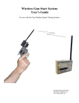
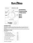
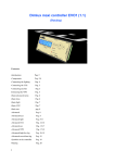
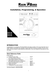
Wireless Grip Switch System
User’s Guide
For use with the Time Machine Sports Timing Systems
Developed and maintained by
Flying Feet Computers, Inc.
www.timemachine.org
INSTRUCTION TO THE USER
This equipment has been tested and found to comply with the limits for a class B digital device, pursuant to part 15 of the FCC Rules.
These limits are designed to provide reasonable protection against harmful interference in a residential installation. This equipment
generates, uses and can radiate radio frequency energy and if not installed and used in accordance with the instructions, may cause harmful
interference to radio communications. However, there is no guarantee that interference will not occur in a particular installation. If this
equipment does cause harmful interference to radio or television reception, which can be determined by turning the equipment off and on,
the user is encouraged to try to correct the interference by one or more of the following measures:
•
•
•
•
Reorient or relocate the receiving antenna.
Increase the separation between the equipment and receiver.
Connect the equipment into an outlet on a circuit different from that to which the receiver is connected.
Consult the dealer or an experienced radio/TV technician for help.
In order to maintain compliance with FCC regulations, shielded cables must be used with this equipment. Operation with non-approved
equipment or unshielded cables is likely to result in interference to radio and TV reception. The user is cautioned that changes and
modifications made to the equipment without the approval of manufacturer could void the user's authority to operate this equipment.
The Receiver Unit has been tested to comply with FCC standards. FOR HOME OR OFFICE USE.
Latest revision: 7-12-13
2
Thank you for purchasing the Wireless Grip Switch System for use with your Time Machine sports timing system. The
Wireless Grip Switch System provides you with a convenient wireless link between your Time Machine and up to 10 Grip
Switch timing buttons for distances of up to 500 feet. The wireless system utilizes high quality RF technology and
components to provide you with a reliable timing solution.
The Wireless Grip Switches are rugged, sealed, and waterproof. They also feature a sophisticated power circuit utilizing an
internal battery that does not require replacement. The battery will typically last for up to 20 years (depending on usage) or
up to approximately 1.6 million clicks of the button.
In addition to directly replacing the standard “wired” timing buttons, the Wireless Grip Switch System can enhance your
operation by providing wireless connectivity to multiple Time Machines at the same time. If you use more than one Time
Machine to collect timing data, a single Wireless Grip Switch can easily be assigned to start all Time Machines
simultaneously and then trigger any lane/chute input of any of the machines – provided that each machine has a receiver unit
connected.
I. Description
Status LED And
Programming Control Switch
RF Channel Number Label
Thumbscrew Fasteners
Multilane Port Extension Connector
Receiver Unit
Wireless Grip Switch
The Wireless Grip Switch System (WGSS) consists of two components: a Receiver Unit and one or more Wireless Grip
Switches. The Receiver unit plugs onto the multi-lane port connector of your Time Machine. Power for the Receiver unit is
supplied by the Time Machine through the multi-lane port and must be connected to the Time Machine before turning the
Time Machine’s power switch on in order to avoid causing a glitch on the Time Machine’s internal power supply. When
the Time Machine is powered up, the Receiver Unit turns on and is ready to receive signals from any Wireless Grip Switch
that it has been programmed to respond to.
Each Wireless Grip Switch transmits a unique ID code when triggered and it is transmitted over one of 10 different RF
channels. As long as each grip switch being used is transmitting over a different RF Channel, then they will not interfere
with each other if triggered at the same time (within 1/10 sec). If they are not triggered at the same time, then interference
will not be an issue. In order to avoid the possibility of interference, the user must be careful to insure that all of the
Wireless Grip Switches being used are operating on different RF Channels. The RF Channel is pre-programmed at the
factory and is displayed on the antenna. If you received a “set” of Wireless Grip Switches, then they will all have different
RF Channel settings. However, if you acquire additional Wireless Grip Switches, then you may have some with the same RF
Channel number. If this is the case, the RF Channel number can easily be changed by the user to eliminate any possible
interference problems. Please refer to section III on changing the RF Channel Number of a Wireless Grip Switch.
Wireless Grip Switches are assigned Lane/Chute numbers (and “start” functions) by programming the Receiver Unit. When
programmed, the Receiver Unit stores the grip switch ID codes in memory so that it can recognize a transmitted ID code and
then respond by asserting the associated Lane/Chute input to the Time Machine. The Receiver Unit is pre-programmed at the
factory, but it can very easily be reprogrammed by the user. Please refer to section II on Programming the Receiver unit.
The Receiver unit also extends all of the Multilane Port signals out to a 25-pin connector allowing you to use all of the
common accessories that connect to the Multilane Port.
3
II. Programming the Receiver Unit
Each Receiver Unit must be programmed to detect and interpret the Wireless Grip Switches that are to be used with the
system. After the Receiver is programmed, this information is saved in non-volatile memory and used by the receiver to
interpret and respond whenever a Grip Switch is triggered. Once the Receiver Unit has been initially programmed, it does
not need to be reprogrammed again unless a Grip Switch assignment needs to be changed. It will always have the same grip
switch assignment in memory each time the system is powered on – or until the user decides to change it.
Your Wireless Receiver was pre-programmed at the factory to respond to the Wireless Grip Switches that you received with
your system; however you can easily reprogram it to provide the following:
• Change the Lane/Chute number of any grip switch that has previously been assigned.
• Change any grip switch to function as a “Start” button.
• Change any grip switch to function as a “Start-then-Time” button for a desired Lane/Chute number.
• Add additional grip switch assignments.
• Remove a specific grip switch assignment from memory.
• Remove all grip switch assignments from memory.
Programming the Receiver is accomplished by a simple 3 step process:
(NOTE: Time Machine must be in the Cross-Country Timing Mode with Select-Time Trigger set to [KEYBRD] AND RS232 Handshake must be
Disabled/Off – these are the factory default settings)
1.
2.
3.
NOTE: Make Sure Printer ON/OFF Switch Is OFF
Press the Programming Control Switch (the Status LED) and hold for 3 seconds.
Enter the Assignment Code using the Time Machine’s keyboard then press the ENTER key.
Press the button of a “selected” grip switch being assigned
Prior to pressing the Programming Control Switch, make sure that the Time Machine is in the Cross-Country timing mode
with Select-Time Trigger set to [KEYBRD] and that the RS232 Handshake line is Disabled/Off (this is its default state –
refer to pgs 2-7 & 2-9 in the Time Machine User’s Manual). Pressing the Programming Control Switch causes the receiver to
enter the programming mode. Entry into the programming mode is signified by sounding 4 “beeps” along with an orange
status LED blinking On/Off. When in the programming mode, the Receiver will “stop” the Time Machine’s clock (if it was
running) and then set the Time Machine’s Event number to 255. This tells the user that an assignment code may now be
entered using the Time Machine’s keyboard.
The Assignment Code tells the Receiver how to interpret a received Grip Switch signal. Refer to the “Wireless Grip Switch
Assignment Codes” below for a complete list. Basically, if you just want to assign a Lane/Chute number to the switch, then
the assignment code is simply that number: For example, if you want a grip switch to be assigned to “1”, then you would
press the numeric “1” key on the Time Machine’s keyboard and then press ENTER. At this point, the Receiver
acknowledges that input by blinking the status LED Orange/Green and then waits for you to press a grip switch button.
Pressing a grip switch button causes the Receiver to store the grip switch ID code along with the “assigned number” into
memory so that it can interpret the grip switch function whenever the grip switch’s button is pressed. This also causes the
Receiver to exit the programming mode – which is signified by sounding 4 “beeps”. After exiting the programming mode,
the Receiver changes the Time Machine’s Event number to 1. Therefore, the user may need to change the Event number if
Event 1 has already been used and contains timing data.
Wireless Grip Switch Assignment Codes:
Code
Description
1
Assign Selected Grip Switch to 1 (Chute1 for X-C, Lane1 or 1st Place for Track)
2
Assign Selected Grip Switch to 2
:
:
:
10
Assign Selected Grip Switch to 10
50
Assign Selected Grip Switch to a Start-Only Function
51
Assign Selected Grip Switch to “Start-then-Time 1”
52
Assign Selected Grip Switch to “Start-then-Time 2”
:
:
:
510
Assign Selected Grip Switch to “Start-then-Time 10”
100
Remove all Grip Switch and Start-Gun Transducer Assignments from memory
0
Remove Selected Grip Switch or Start-Gun Transducer Assignment from memory
500
Assign Wireless Gun-Start Transducer with no Correction to Start the Time Machine
524
Assign Wireless Gun-Start Transducer with .24sec “Manual Timing Correction” for Starting
999
Enter into Grip Switch RF Channel Programming Mode (see section III)
4
III. Displaying or Changing the RF Channel Number of a Wireless Grip Switch
All Wireless Grip Switch RF Channels are pre-programmed at the factory and the channel number is displayed at the base of
the antenna. Each Wireless Grip Switch should be transmitting on a different RF Channel in order to avoid interference –
just in case they are triggered at the same time. If you need to change an RF Channel number or just check the RF Channel
number of a Grip Switch, then this can easily be accomplished using the Receiver Unit along with the Time Machine display.
The RF Channel number can be displayed and/or changed by putting the Receiver into the “RF Channel Programming”
mode. This mode is entered by using the assignment code of 999 when programming the Receiver Unit (see section II). The
Receiver signifies that it has entered into the RF Channel Programming mode by toggling the status LED between Green and
Red. This tells the user that it is waiting for a Grip Switch button to be pressed. When a Grip Switch button is pressed, the
Receiver will sound a “beep” and then display the switch’s RF Channel number in the upper-right corner of the Time
Machine’s display (just above the “st0.00” characters). If the user would like to change the RF Channel number, then the
Grip Switch button needs to be pressed again, but this time “held down” for approximately 6 seconds until the channel
number increments to the next value. As long as the button is being held down, the channel number will continue to
increment every 2 seconds (rolling over from 10 to 1). When the desired channel number is reached, the user must release
the button. The Wireless Grip Switch’s RF Channel will then be set to the desired number. After the button is released, the
Receiver will automatically exit from the “RF Channel Programming” mode within a few seconds.
To Display the RF Channel number of a Wireless Grip Switch:
(NOTE: Time Machine must be in the Cross-Country Timing Mode with Select-Time Trigger set to [KEYBRD] AND RS232 Handshake must be
Disabled/Off – these are the factory default settings)
1.
2.
3.
NOTE: Make Sure Printer ON/OFF Switch Is OFF
Press the Programming Control Switch (the Status LED) and hold for 3 seconds.
Enter the Assignment Code “999” using the Time Machine’s keyboard then press the ENTER key.
Press the button of a “selected” grip switch and view its channel number in the upper-right corner of the
Time Machine’s display.
To Change the RF Channel number of a Wireless Grip Switch:
(NOTE: Time Machine must be in the Cross-Country Timing Mode with Select-Time Trigger set to [KEYBRD] AND RS232 Handshake must be
Disabled/Off – these are the factory default settings)
1.
2.
3.
4.
NOTE: Make Sure Printer ON/OFF Switch Is OFF
Press the Programming Control Switch (the Status LED) and hold for 3 seconds.
Enter the Assignment Code “999” using the Time Machine’s keyboard then press the ENTER key.
Press and hold the button of a “selected” grip switch and view its channel number in the upper-right corner
of the Time Machine’s display.
Continue holding the button until the desired channel number is displayed, then release the button.
NOTE:
After an RF Channel number has been changed, the user should apply a new label (or replace the existing label) to display the current RF Channel number of
the Wireless Grip Switch.
IV. Using the Wireless Grip Switch System
The Wireless Grip Switch System comes pre-programmed and ready-to-use out of the box. Just connect the Wireless
Receiver Unit to your Time Machine’s Multilane Port connector, turn the Time Machine on and you are ready to start timing
a race.
One of the Wireless Grip Switches you received will have a “Start” label on it (likely the “1” switch). This Grip Switch will
be used for starting the Time Machine’s internal time clock – plus it will time competitors across Lane/Chute 1 (or possibly
time the 1st place finisher in track mode). For accurate timing, it is necessary that you use either the Wireless “Start”
Button or the Wireless Gun-Start Transducer to start the Time Machine’s clock. The Wireless Receiver Unit uses a
sophisticated software algorithm to manage multiple grip switch signals simultaneously; however this processing causes a
time latency of approximately 0.16 seconds. This time latency is exactly the same for wireless starts as it is for wireless
finishes. Therefore using a wireless start will exactly cancel out the latency required for the wireless finishes – providing an
accurate timing result.
The resolution of the Wireless Grip Switch system is much greater than the 1/100th sec resolution of the Time Machine’s
internal clock – so there is no compromise of timing accuracy when compared to using “wired” grip switches.
5
V. Warranty Statement
The manufacturer warrants the original purchaser of the WIRELESS GRIP SWITCH SYSTEM (WGSS) that it shall be free
of defects resulting from faulty manufacturer of the product or its components for a period of one year from the date of sale.
Defects covered by this warranty shall, at the option of the manufacturer, be corrected either by repair or by replacement. The
replaced components will be warranted for the remainder of the original one year period.
The sole obligation of the manufacturer under this warranty is limited to repair or replacement of products pertaining to the
WGSS only, which prove to be defective within one year of purchase. The manufacturer shall not, in any event, be liable for
any consequential damages or loss of profits of any kind resulting from the use of the WGSS or the technical information
enclosed in this document.
Please fill out the Product Registration Form and fax, email or mail it to Flying Feet Computers, Inc. This product must be
registered within thirty (30) days from the date of purchase in order to activate your warranty coverage.
____________________________________________________________________________________
Product Registration Form
Please fill out the following information and fax, email or send it to:
Flying Feet Computers, Inc.
11112 204th Ave Ct. East
Bonney Lake, WA 98391
(800) 328-4070 ph.
(253) 863-1689 fax
www.timemachine.org
By sending this form back to us, we can let you know of additional products and upgrades as they become available. This
form is also used to activate your warranty coverage.
Name
Company Name
Phone#
Address
Cell#
City
Purchased From
State
Date Purchased
Email
Zip
6