1
Service Manual
RBC 60
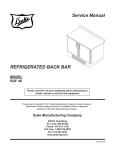
REFRIGERATED BACK
COUNTER
RBC 48
MODEL
RBC 48
RBC 60
Please read this manual completely before attempting to
install, operate or service this equipment
This manual is Copyright © 2011 Duke Manufacturing Co. All rights reserved.
Reproduction without written permission is prohibited. Duke is a registered
trademark of the Duke Manufacturing Co..
Duke Manufacturing Co.
2305 N. Broadway
St. Louis, MO 63102
Phone: 314-231-1130
Toll Free: 1-800-735-3853
Fax: 314-231-5074
www.dukemfg.com
P/N 219211B
Service Manual for Refrigerated Back Counter RBC 48/60
IMPORTANT WARNING AND SAFETY INFORMATION
WARNING
READ THIS MANUAL THOROUGHLY BEFORE OPERATING, INSTALLING, OR PERFORMING MAINTENANCE ON THE EQUIPMENT.
WARNING
FAILURE TO FOLLOW INSTRUCTIONS IN THIS MANUAL CAN CAUSE PROPERTY
DAMAGE, INJURY OR DEATH.
WARNING
DO NOT STORE OR USE GASOLINE OR OTHER FLAMMABLE VAPORS OR LIQUIDS
IN THE VICINITY OF THIS OR ANY OTHER APPLIANCE.
WARNING
UNLESS ALL COVER AND ACCESS PANELS ARE IN PLACE AND PROPERLY SECURED, DO NOT OPERATE THIS EQUIPMENT.
CAUTION
Observe the following:
•
Minimum clearances must be maintained from all walls and combustible materials.
•
Keep the equipment area free and clear of combustible material.
•
Adequate clearance for air openings.
•
Unit exhausts air to the bottom and the rear.
•
Do not set unit on a curb or seal to the wall.
•
Do not block the slots in the front kickplate.
•
Operate equipment only on the type of electricity indicated on the specification plate.
•
Retain this manual for future reference.
2
Service Manual for Refrigerated Back Counter RBC 48/60
CONTENTS
INTROUCTION........................................................................................................................................ 4
SPECIFICATIONS............................................................................................................................. 4
INSTALLATION.................................................................................................................................. 4
Location....................................................................................................................................... 4
Inside Unit.................................................................................................................................... 4
Outside Unit................................................................................................................................. 4
Leveling....................................................................................................................................... 4
Stabilizing.................................................................................................................................... 4
Electrical Connection................................................................................................................... 5
MAINTENANCE...................................................................................................................................... 6
STAINLESS STEEL CARE AND CLEANING.................................................................................... 6
PREVENTIVE MAINTENANCE......................................................................................................... 6
Cleaning the Condenser Coil....................................................................................................... 6
Gasket Maintenance.................................................................................................................... 7
Drain Maintenance - Base........................................................................................................... 7
PARTS REPLACEMENT......................................................................................................................... 8
THERMOSTAT REPLACEMENT...................................................................................................... 8
EVAPORATOR FANS........................................................................................................................ 8
REFRIGERATION SYSTEM UNIT REPLACEMENT........................................................................ 9
DOOR REPLACEMENT AND ADJUSTMENT................................................................................... 9
DOOR GASKET REPLACEMENT.................................................................................................... 9
MULLION AND CABINET HEATER REWIRING............................................................................... 9
General........................................................................................................................................ 9
Mullion Heater.............................................................................................................................. 9
RECHARGING REFRIGERANT SYSTEM..................................................................................... 10
General...................................................................................................................................... 10
Tools Required........................................................................................................................... 10
Charging Procedure................................................................................................................... 10
TROUBLESHOOTING...........................................................................................................................11
WIRING DIAGRAMS............................................................................................................................. 12
CUSTOMER ASSISTANCE................................................................................................................... 15
3
Service Manual for Refrigerated Back Counter RBC 48/60
INTROUCTION
SPECIFICATIONS
MODEL DESCRIPTION
AMPS
PH.
RBC 48
48" Refrigerated 120 VAC (60 Hz)
Back Counter
220 VAC (50 Hz)
10
5
1
1
RBC 60
60" Refrigerated 120 VAC (60 Hz)
Back Counter
220 VAC (50 Hz)
12
6
1
1
MODEL DESCRIPTION
VOLTAGE
WIDTH
LENGTH
RBC 48
48" Refrigerated 40.00 In.
Back Counter
HEIGHT
29.50 In.
48.00 In.
RBC 60
60" Refrigerated 40.00 In.
Back Counter
29.50 In.
60.00 In.
INSTALLATION
Location
Units represented in this manual are intended for
indoor use only. Be sure the location chosen has a
floor or counter strong enough to support the total
weight of the units. Reinforce the floor or counter
if necessary to provide for maximum loading. For
the most efficient operation, be sure to provide
good air circulation inside and out. These units
should be located so that they can be moved for
service. Major service to the refrigeration system
is done from the end of the cabinet.
The outline dimensional drawings for the units are
shown below in Figures 1 and 2.
Figure 2
60" Refrigerated Back Counter (RBC 60)
Inside Unit
Take care not to block air flow to the fans and allow
space along the front, back and sides.
Outside Unit
Be sure that the unit has access to ample air; avoid
hot corners and locations near stoves and ovens.
CAUTION: This unit exhausts air to the
bottom and the back. Do not
seal the unit to the wall or set
unit on a curb. The ventilation
slots in the kickplate must
remain open.
Leveling
Be sure that the units are placed on a firm, flat
surface/floor. Check for cracks in flooring or tile
and avoid these areas if possible. If necessary
place support pads, properly rated for the weight
of the unit, to “bridge” uneven or cracked flooring.
Level unit accordingly.
Stabilizing
Figure 1
48" Refrigerated Back Counter (RBC 48)
4
Use the leg adjustments to insure that the unit is
solid to the floor surface at all four contact points.
Insure that the unit does not “rock” when pressure
is applied to the top corners.
Service Manual for Refrigerated Back Counter RBC 48/60
Electrical Connection
The RBC 48 and RBC 60 are available as a 120VAC,
60 Hz or as 220VAC, 50 Hz dependent on model.
All electrical connections should be performed by
a certified electrician and should comply with local
electrical codes for your municipality.
WARNING
REFER TO THE AMPERAGE DATA
LIST IN THE SPECIFICATIONS OR
THE SERIAL TAG DATA AND YOUR
LOCAL CODE OR THE NATIONAL
ELECTRICAL CODE TO BE SURE UNIT
IS CONNECTED TO THE PROPER
POWER SOURCE.
A PROTECTED
CIRCUIT OF THE CORRECT VOLTAGE
AND AMPERAGE MUST BE RUN FOR
CONNECTION OF THE SUPPLY CORD
OR PERMANENT CONNECTION TO THE
UNIT. THE POWER MUST BE TURNED
OFF AND DISCONNECTED WHENEVER
PERFORMING MAINTENANCE OR REPAIR FUNCTIONS.
5
Service Manual for Refrigerated Back Counter RBC 48/60
MAINTENANCE
STAINLESS STEEL CARE AND CLEANING
To prevent discoloration or rust on stainless
steel several important steps need to be taken.
Stainless steel contains 70-80% iron which
will rust. It also contains 12-30% chromium
which forms an invisible passive film over the
steels surface which acts as a shield against
corrosion. As long as the protective layer is
intact, the metal will not corrode. If the film is
broken or contaminated, outside elements can
begin to breakdown the steel and begin to form
rust or discoloration.
Proper cleaning of stainless steel requires soft
cloths or plastic scouring pads.
CAUTION: Never use steel pads, wire brushes or scrapers.
CAUTION: Never use an acid based
cleaning solution! Many food
products have an acidic content
which can deteriorate the
finish. Be sure to clean all food
products from any stainless
steel surface. Common items
include, tomatoes, peppers and
other vegetables.
WARNING
THE POWER MUST BE TURNED OFF
AND DISCONNECTED AT ALL TIMES
WHEN PERFORMING MAINTENANCE
OR REPAIR FUNCTIONS.
PREVENTIVE MAINTENANCE
Cleaning solutions need to be alkaline based or
non-chloride cleaners. Any cleaner containing
chlorides will damage the protective film of the
stainless steel. Chlorides are also commonly found
in hard water, salts and household and industrial
cleaners. If cleaners containing chlorides are used,
be sure to rinse repeatedly and dry thoroughly
upon completion.
Routine cleaning of stainless steel can be done
with soap and water. Extreme stains or grease
should be cleaned with a non-abrasive cleaner and
plastic scrub pad. It is always good to rub with the
grain of the steel. There are also stainless steel
cleaners available which can restore and preserve
the finish of the steels protective layer.
Cleaning the Condenser Coil
The condenser coil is located behind the filter
panel and is accessed through the front of the
unit (See Figure 3). The condenser coil requires
regular cleaning and is recommended every 60
days. However, in some instances you may find
that there is a large amount of debris, dust or
grease that has accumulated prior to the 60 day
time frame. In these cases the condenser coil
should be cleaned every 30 days.
Early signs of stainless steel breakdown can
consist of small pits and cracks. If this has
begun, clean thoroughly and start to apply stainless
steel cleaners in attempt to restore the passivity
of the steel.
Figure 3
Location of Filter and Condensing Coil
6
Service Manual for Refrigerated Back Counter RBC 48/60
If the build up on the coil consists of only light dust
and debris the condenser coil can be cleaned with
a simple brush, heavier dust build up may require
a vacuum or even compressed air to blow through
the condenser coil.
If heavy grease is present there are de-greasing
agents available for refrigeration use and
specifically for the condenser coils. The condenser
coil may require a spray with the de-greasing agent
and then blown through with compressed air.
Failure to maintain a clean condenser coil can
initially cause high temperatures and excessive
run times, continuous operation with dirty or
clogged condenser coils can result in compressor
failures. Neglecting the condenser coil cleaning
procedures will void any warranties associated with
the compressor or cost to replace the compressor.
CAUTION: Never use a high-pressure water
wash for this cleaning procedure
as water can damage the
electrical components located
near or at the condenser coil.
Drain Maintenance - Base
Each unit has a copper drain tube located inside
the unit which removes the condensation from
the evaporator coil and deposits it onto a drain
pan where it can evaporate (See Figure 4). If
you notice excessive water accumulation on the
inside of the unit be sure that the drain tube is
connected from the evaporator housing to the
condensate evaporator drain pan. If water is
collecting underneath the unit you may want to
check the condensate evaporator drain tube to
be sure it is still located above the drain pan.
The leveling of the unit is also important as the
units are designed to drain properly when on a
level surface, if your floor is not level this can also
cause drain problems. Be sure the drain pan is
kept free of dirt, dust and other debris as excessive
amounts will cause water to back up and overflow
from the drain pan.
Gasket Maintenance
Gaskets require regular cleaning to prevent mold
and mildew build up and also to keep the elasticity
of the gasket. Gasket cleaning can be done with
the use of warm soapy water. Avoid full strength
cleaning products on gaskets as this can cause
them to become brittle and prevent proper seals.
Also, never use sharp tools or knives to scrape
or clean the gasket which could possibly tear the
gasket and rip the bellows.
Gaskets can easily be replaced and do not require
the use of tools or authorized service persons. The
gaskets are “Dart" style and can be pulled out of
the groove in the door and new gaskets can be
“pressed" back into place.
Figure 4
Location of Drain Tube and Drain Pan
7
Service Manual for Refrigerated Back Counter RBC 48/60
PARTS REPLACEMENT
THERMOSTAT REPLACEMENT
EVAPORATOR FANS
The thermostat is located inside the main electrical
control box and is accessible through the right
side door.
The evaporator fans are a part of the main
refrigeration unit. The refrigeration unit is
accessed through the right side of the unit and is
slid out as an assembly from the right side.
1. Disconnect and isolate the refrigerator from
the power source.
2. Remove upper sheet metal shroud behind right
side door to gain full access to control box.
3. Remove the control box from the unit.
4. Remove the thermostat from the control box.
5. Remove interior ductwork from the right, inside
of the unit to gain access to the evaporator fan
assemble.
6. Remove the evaporator fan assembly.
7. Remove the thermostat control cap tube from
the evaporator coil.
8. Remove thermostat from the unit.
9. Install replacement thermostat.
10.Replace the thermostat control cap tube.
11.Replace the evaporator fan assembly.
12.Replace all ductwork, reinstall the thermostat
into the control box and reinstall the control
box.
1. Disconnect and isolate the refrigerator from
the power source.
2. Remove right rear corner angle strip.
3. Completely remove the right side laminate
panel from its guide way.
4. Remove the inner, right side access panel.
5. Remove the refrigeration unit main mounting
hardware.
6. Slide the entire refrigeration unit out through
the right side as an assembly.
7. Disconnect and label the evaporator fan wiring.
8. Remove the evaporator fan mounting
hardware.
9. Remove the evaporator fan.
10.Install the replacement evaporator fan.
11.Replace evaporator fan mounting hardware.
12.Reconnect the evaporator fan wiring.
13.Replace the sheet metal shroud.
13.Slide the refrigeration unit back to original
mounting position.
14.Reconnect main power source and test
refrigeration unit.
14.Replace and secure the refrigeration unit main
mounting hardware.
NOTE: Care should be taken not to kink the new
thermostat cap tube.
NOTE: 8" of the end of the thermostat cap tube
must be in the evaporator coil to ensure proper
operation.
8
15.Replace side access panel, laminate panel
and right rear corner angel strip.
16.Reconnect main power source and test the
refrigeration unit.
Service Manual for Refrigerated Back Counter RBC 48/60
REFRIGERATION SYSTEM UNIT
REPLACEMENT
1. Disconnect and isolate the refrigerator from
the power source.
2. Remove right rear corner angle strip.
3. Completely remove the right side laminate
panel from its guide way.
4. Remove the inner, right side access panel.
5. Remove the refrigeration unit main mounting
hardware.
6. Slide the entire refrigeration unit out through
the right side as an assembly.
7. Install the replacement refrigeration unit onto
the slide bars.
8. Slide the replacement refrigeration unit back
to its mounting position.
9. Replace and secure the refrigeration unit main
mounting hardware.
10.Replace side access panel, laminate panel
and right rear corner angel strip.
11.Reconnect main power source and test
refrigeration unit.
DOOR GASKET REPLACEMENT
The door gasket is pulled from its retainer.
1. Starting in a corner, firmly pull the gasket from
the retaining channel.
2. To reinstall, start in the corner and firmly press
the gasket into the retaining channel.
MULLION AND CABINET HEATER
REWIRING
General
In the event of mullion or cabinet heater failure,
rewiring to the alternate heater (HTR2) is
required.
Mullion Heater
The mullion heater is accessed behind the
angle bracket that attaches the mullion to the main
cabinet. The cabinet heater is accessed through
the right side cabinet by removing the laminate
from the right side of the unit.
Remove appropriate wire nuts (mullion heater) or
spade connectors (cabinet heater) and transfer
the supply power to the alternate heater.
DOOR REPLACEMENT AND ADJUSTMENT
Doors may become misaligned during shipment
but can be easily adjusted.
1. On the door that is hanging low, tighten hinge
screws on top and bottom hinge with a 3/8"
open wrench until snug. Do not over tighten.
2. Place a flat screwdriver against the side of the
bottom hinge and lightly tap with a hammer
until door is properly aligned.
3. Depending upon the degree of misalignment,
it may be necessary to adjust the top hinge
as well by gently tapping on the inside of the
hinge.
4. Once doors have been aligned, assure that
all screws are tight on all of the hinges.
9
Service Manual for Refrigerated Back Counter RBC 48/60
RECHARGING REFRIGERANT SYSTEM
General
To analyze the performance of a refrigeration
system; temperature readings can be taken and
converted to pressures using a standard pressure/
temperature chart.
When access into a factory sealed refrigeration
system is necessary to perform service, the
following procedure must be followed to ensure
the system is returned to a properly sealed state.
Tools Required
•
Standard hand and refrigeration service tools,
no special tools needed.
•
Refrigerant Type: R-134A 8 ounces
Charging Procedure
NOTE: When service of the refrigeration system
is necessary, care must be given during the
evacuation process to ensure removal of air,
moisture, and other non-condensables from the
system. To evacuate the refrigeration system
properly, Duke Manufacturing recommends a
triple evacuation procedure outlined
below. Failure to follow this process could
cause poor performance of the
refrigeration system.
•
Evacuate system to 1500 microns
•
Break the vacuum to 2 psig with dry
nitrogen, if dry nitrogen is unavailable use
the same type of refrigerant as used in the
system
•
Evacuate system to 1500 microns
•
Break the vacuum to 2 psig with dry
nitrogen, if dry nitrogen is unavailable use
the same type of refrigerant as used in the
system
•
Evacuate system to 500 microns
The system is now ready to receive the refrigerant
charge per the data plate information.
10
CAUTION: Never use oxygen or acetylene
in place of refrigerant and dry
nitrogen for leak testing. A
violent explosion may result,
causing personal injury or death.
Always use a pressure regulator
when using nitrogen to pressure
test. Failure to do so will result in
extremely high pressure which
could exceed the burst pressure
of the compressor or other
system components and result
in personal injury or death.
NOTE: Before beginning the repair, ensure there
is enough of the process tube present to complete
the repair using the above procedure. If not, install
a new process tube (approximately 12") before
beginning the repair sequence.
1. Install a temporary access valve on the high
and low side process tubes as close to the
factory crimps as possible.
2. Through the use of temporary valves, (Duke
Manufacturing will not reimburse the cost of
permanently installed valves) perform the
required service needed to repair the unit.
3. Once the repair has been made, evacuate
the system using the triple evacuation method
described in Duke Manufacturing Service
Bulletin Number 26. After the evacuation is
complete, recharge the system as stated on
the nameplate, using the proper refrigerant,
Continue by crimping the process tube just
below the temporary valve and again 2" below
the crimp just made. Leaving the crimp tool
in place, remove the temporary valve, braze
shut the end of the process tube, allow to cool
(approximately “5 minutes" time), remove the
crimp tool, and leak check the brazed end.
Service Manual for Refrigerated Back Counter RBC 48/60
TROUBLESHOOTING
SYMPTOM
Cabinet too warm
Cabinet too cold
Water in the bottom of
the unit
CAUSE
REMEDY
Unit not plugged in
Plug unit in
Thermostat set too warm
Set thermostat colder, the
higher the number, the
colder the unit will be
Faulty thermostat, in the
coldest position, the switch is
not closed
Replace thermostat
Doors not sealing
Adjust doors
Torn or damaged door
gaskets
Replace gaskets
Evaporator fan not running
Check motor, repair or
replace
Condenser fan motor not
running
Check motor, repair or
replace
Condenser coil dirty/ filter dirty
Clean coil or filter
Refrigerant leak
Leak check unit, repair,
and recharge
Thermostat set too cold
Turn thermostat to a
warmer setting, the higher
the number, the colder the
unit will be
Faulty thermostat, in the off
position, the switch does not
open, stuck closed
Replace thermostat
Drain tube plugged
Clear drain tube
Drain tube loose or
disconnected from drain pan
Tighten or re-connect
drain tube
11
Service Manual for Refrigerated Back Counter RBC 48/60
FAN 2
Black
(VS)
Black
(VS)
Black
(VS)
White
Black
(VS)
FAN 1
Black
WIRING DIAGRAMS
EVAPORATOR
COMPARTMENT
REFRIGERATED BODY
POWER SAVE
SWITCH
220V 120V
Red Black
(VS) (VS)
White
(VS)
HTR 1
DOOR HEATER
Red
120= 220=
Black Black
Smooth (VS)
(VS)
G
White
(VS)
Black
SO
White
SO
White
(VS)
(VS = Vendor Supplied)
Subject to change
12
120= 220=
Black White
with
(VS)
Grooves
(VS)
L1
L2
Green / Green w/Yellow
120V 220V
Black Red
(VS) (VS)
1
Red
White / Blue
120V 220V
Black Red
(VS) (VS)
3 2
Black
Black / Brown
HTR 2
MULLION HEATER
HTR 1
Black
THERMOSTAT
SWITCH
White
SPLICE
( AT BASE OF MULLION )
HTR 2
220V 120V
Red Black
(VS) (VS)
White
(VS)
HEATER
SWITCH BOX
Green
POWER SAVE ON
LIGHT OFF
G
CONTROL
BOX
COMPRESSOR
TRAY
Green
(VS)
Service Manual for Refrigerated Back Counter RBC 48/60
220V 50/60 Hz
L1
G
120V 50/60 Hz
L2
L1
CONDENSING UNIT
S1
THRERMOSTAT
G
CONDENSING UNIT
S1
R1
THRERMOSTAT
M1
EVAPORATOR FAN
M2
M2
EVAPORATOR FAN
DOOR HEATER
HTR2
POWER SAVE
SWITCH
R2
HTR1
R3
HTR1
R1
M1
EVAPORATOR FAN
S2
L2
EVAPORATOR FAN
DOOR HEATER
HTR2
S2
POWER SAVE
SWITCH
R2
HTR1
R3
HTR1
HTR2
HTR2
MULLION HEATER
MULLION HEATER
NOTE: HTR2 IS A FAULT BACKUP FOR HTR1 IN THE HEATER ASSEMBLIES.
13
Service Manual for Refrigerated Back Counter RBC 48/60
NOTES
14
Service Manual for Refrigerated Back Counter RBC 48/60
CUSTOMER ASSISTANCE
To aid in reporting this unit in case of loss or theft, please record below the model number and serial number
located on the unit. We also suggest you record all the information listed and retain for future reference.
MODEL NUMBER_________________________ SERIAL NUMBER_ _______________________ DATE OF PURCHASE_____________________________________________________________ ________________________________________
DEALER_________________________________ TELEPHONE_ ___________________________ SERVICER_______________________________ TELEPHONE_ ___________________________
NORTH AMERICA & LATIN AMERICA
UK & IRELAND
Duke Manufacturing Company
2305 N. Broadway
St. Louis, MO 63102
Phone: 314-231-1130
Toll Free: 1-800-735-3853
Fax: 314-231-5074
Duke Mfg UK
Duke House
Unit 10, Greendale Business Park
Woodbury Salterton
Exeter
Devon - UK EX5 1EW
Tel: 01395 234140
FAX: 01395 234154
CONTINENTAL EUROPE
ASIA
EU Headquarter Office
Duke Manufacturing
CR s.r.o. Vitavska 219,
Stechovice 25207
Phone: +420 257-741-033
Asia Office
Duke Food Service Equipment (shanghai)
Company Limited
1F, Building #17-2,
658 Nong Jin Zhong Road
Shanghai, China 200335
Tel: +86 21 6876 9272
Fax: +86 21 33600628
TO ACCESS INTERNET: www.dukemfg.com
Please provide the following information when you write or call: model number, serial number, date of
purchase, your complete mailing address (including zip code), and description of the problem.
15
Service Manual for Refrigerated Back Counter RBC 48/60
Duke Manufacturing Company
2305 N. Broadway
St. Louis, MO 63102
Phone: 314-231-1130
Toll Free: 1-800-735-3853
Fax: 314-231-5074
www.dukemfg.com
EU Headquarter Office
Duke Manufacturing
CR s.r.o. Vitavska 219,
Stechovice 25207
Phone: +420 257-741-033
Duke Mfg UK
Duke House
Unit 10, Greendale Business Park
Woodbury Salterton
Exeter
Devon - UK EX5 1EW
Tel: 01395 234140
FAX: 01395 234154
Asia Office
Duke Food Service Equipment (shanghai) Company Limited
1F, Building #17-2,
658 Nong Jin Zhong Road
Shanghai, China 200335
Tel: +86 21 6876 9272
Fax: +86 21 33600628
16
PN 219211