1
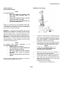
TM 10-3930-671-24
TECHNICAL MANUAL
ORGANIZATIONAL, DIRECT SUPPORT, AND GENERAL SUPPORT
MAINTENANCE MANUAL
INTRODUCTION AND GENERAL
INFORMATION
1-1
ORGANIZATIONAL
TROUBLESHOOTING
2-1
ORGANIZATIONAL
MAINTENANCE
3-1
DIRECT SUPPORT/GENERAL SUPPORT
TROUBLESHOOTING
4-1
DIRECT SUPPORT/GENERAL SUPPORT
MAINTENANCE
5-1
REFERENCES
A-1
MAINTENANCE ALLOCATION
CHART(MAC)
B-1
EXPENDABLE/DURABLE SUPPLIES
AND MATERIALS LIST
C-1
SCHEMATICS AND DIAGRAMS
D-1
LUBRICATION ORDER
E-1
COMMERCIALPLANNED MAINTENANCE
AND ADJUSTMENTS
F-1
Approved for public release; distribution is unlimited.
HEADQUARTERS, DEPARTMENT OF THE ARMY
MAY 1996
TM 10-3930-671-24
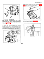
All tools and lifting equipment must
be in good condition, meet the load
capacity requirements and have
OSHA labels when required. Tools
with defects can have failures
causing severe injury or death.
Disconnect the
battery,
before
connecting or disconnecting test
instruments (except voltmeter) or
before removing or replacing any unit
or wiring. Accidental grounding or
shorting at the regulator, alternator,
ammeter or accessories, will cause
severe damage to the units and/or
wiring and possible injury to
personnel.
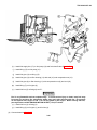
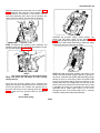
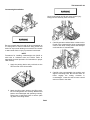
When removing the transaxle with the
truck blocked up by the frame, truck
can tip backwards due to its heavy
counterweight.
Both upright and
counterweight must be removed
before attempting to raise the truck
for transaxle removal. Failure to
remove both could result in injury or
death.
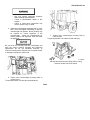
If a booster battery or a fast charger
is used, its polarity must be
connected correctly to prevent
damage to the electrical system
components. Connect positive to
positive,
negative
to
negative.
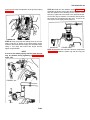
Connect the negative cable ground
connection last (but not to the battery
because an explosion could result).
Battery acid (electrolyte) is extremely
harmful. Always wear safety goggles
and rubber gloves, and do not smoke
when performing maintenance on
batteries. Injury will result if acid
contacts skin or eyes. Wear rubber
apron to prevent clothing being
damaged.
Do not smoke or have open flames or
sparks in battery charging areas or
near batteries.
An explosion can
result and cause injury or death.
The radiator is very hot and
pressurized during vehicle operation.
Let radiator cool before removing
cap. Failure to do so can result in
serious bums.
Review all described procedures
before starting any maintenance or
service function. Failure to follow
this warning can result in serious
injury.
This battery contains corrosive acid
which can cause injury. If acid
contacts your eyes or skin, flush
immediately with water for 15
minutes and get medical assistance.
Keep clear of equipment when
equipment Is being raised or lowered.
Equipment may fall and cause
serious injury or death to personnel.
a
TM 10-3930-671-24
• Dry cleaning solvent (P-D-680) is TOXIC
and
flammable.
Wear
protective
goggles and gloves; use only in a wellventilated area; avoid contact with
skin, eyes, and clothes; and do not
breathe vapors. Keep away from heat
or flame. Never smoke when using
solvent; the flash point for type I drycleaning solvent is 100°F (380C) and for
type II is 140°F (60°C). Failure to do so
may result in injury or death to
personnel.
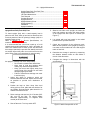
Always put blocks under the carriage
and upright rails when necessary to
work with upright in an elevated
position to prevent injury to
personnel.
Use care when removing or installing
snap and retaining rings. Snap and
retaining rings are under spring
tension and can act as projectiles
when released and could cause
severe eye injury.
• If personnel become dizzy while using
cleaning solvent, immediately get fresh
air and medical help. If solvent
contacts skin or clothes, flush with
cold water. If solvent contacts eyes,
immediately flush eyes with water and
get immediate medical attention.
• Never
dip
or
soak
electrical
components, packings, or rubber,
plastic, or Teflon parts in dry cleaning
solvent. Solvent can react with material
and result in severe damage or
destruction of parts.
Park truck in a well-ventilated area.
Do
not
smoke
or
perform
maintenance near open flame or
other sources of ignition. Do not
disconnect any lines when exhaust
manifold is excessively hot or fires
may result in injuries and damage to
equipment.
Stop engine before checking battery
terminals or electrical connections.
Do not hold ignition wires with bare
hands since shocks or other injuries
can result. Battery acid can cause
corrosive burns. Always wear eye
protection. Use of jumper cables or
battery charging should be done only
as directed by manufacturer's safety
instructions.
• Battery acid (electrolyte) is extremely
harmful. Always wear safety goggles
and rubber gloves, and do not smoke
when performing maintenance on
batteries. Injury will result if acid
contacts skin or eyes. Wear rubber
apron to prevent clothing being
damaged.
• Avoid electrolyte contact with skin,
eyes, or clothing. If battery electrolyte
spills, take immediate action to stop
burning effects:
-
External: Immediately flush with cold running
water to remove all acid.
-
Eyes: Flush with cold water for at least 15
minutes. Seek immediate medical attention.
-
Internal: Drink large amounts of water or milk.
Follow with milk of magnesia, beaten egg, or
vegetable oil. Seek immediate medical attention.
-
Clothing or Vehicle: Wash at once with cold
water. Neutralize with baking soda or household
ammonia solution.
b
TM 10-3930-671-24
Remove all jewelry such as rings, dog
tags, bracelets, etc. If jewelry
contacts battery terminal, a direct
short may result in instant heating of
tools, damage to equipment, and
injury or death to personnel.
All tools and lifting equipment must
be in good condition, meet the load
capacity requirements and have
OSHA labels when required. Tools
with defects can have failures
causing severe injury or death.
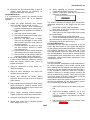
• Use only approved hooks, chains, and
connecting links when lifting and
handling the upright. Be sure the hoist,
hooks, and chain have the correct
capacity to safely handle the load.
Allow
engine
to
cool
before
performing maintenance on the
muffler, exhaust pipe, exhaust pipe,
exhaust manifold. If necessary, use
insulated pads and gloves personal
injury may result.
• Attach a chain or sling of correct
capacity to the upright and a hoist
before removing any tilt cylinder
attachment parts. Be sure upright is
securely supported by the hoist and
slack removed before removing upright
mounting trunnion caps. Failure to do
so could result in personal injury or
death.
Attach a chain or sling to the upright
and a hoist before removing any tilt
cylinder attachment parts.
Some brake linings are still made
with asbestos which when inhaled
has been found to be extremely
dangerous. Do not use compressed
air to clean the brake shoes or other
parts before or after disassembly.
Instead wipe down the assembly and
then the components with damp,
disposable wipers and immediately
discard them safely. Avoid breathing
dust or injury may result.
Adhesive causes immediate bonding
on contact with eyes, skin, or
clothing and also gives off harmful
vapors. Wear protective goggles and
use in well-ventilated area. If
adhesive gets in eyes, try to keep
eyes open; flush eyes with water for
15 minutes and get immediate
medical attention.
Battery service must be done by
trained personnel. Battery acid can
cause severe bums and injury.
Attach lifting device to counterweight
prior to removing mounting bolts. Do
not remove with blocks under
counterweight
supporting
truck.
Failure to follow these procedures as
shown in this manual can result in
severe injury or death.
c
TM 10-3930-671-24
Compressed air used for cleaning
purposes must not exceed regulated
30 psi (207 kPa). Use only with
effective chip guarding and personal
protective
equipment
(goggles/
shield, gloves, etc.) to prevent injury
to personnel.
Do not remove the counterweight
unless you have training and are
familiar with the correct procedures.
Counterweights can fall if not
handled correctly and cause severe
injury or death.
Do not remove the radiator cap when
the radiator is hot. Steam of hot
coolant from the radiator can cause
severe bums. Never remove the
radiator cap while the engine is
running. Stop the engine and wait
until it has cooled.
Corrosion inhibitor contains alkali.
Do
not
get
in
eyes;
wear
goggles/safety glasses when using.
Avoid contact with skin. In case of
contact, immediately wash area with
soap and water. If eyes are contacted,
flush eyes with large amounts of
water for at least 15 minutes and get
immediate medical attention.
Be sure to stand away from path of
the counterweight as it is being lifted
and moved. Watch the lifting chains
and hooks for any unusual twisting
or movement. Do not walk or stand
under the forks or injury to personnel
could result.
Do not allow heavy components to
swing while hanging by lifting device.
Equipment may strike personnel and
cause injury.
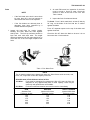
If the fork blade at the heel is worn
down by more than 10%, the load
capacity is reduced and the fork must
be replaced.
Starting fluids or aids such as ether
or gasoline must not be used in a
diesel engine air intake system. The
use of these fluids will cause severe
internal engine damage and/or bodily
injury.
Gasoline is not an acceptable
cleaning solvent because of its
extreme combustibility. It is unsafe in
the workshop environment because it
can ignite and cause injury to
personnel.
Do not operate a lift truck or handle
loads
with
the
counterweight
removed. Failure to follow this
message can result in severe injury
or death.
d
TM 10-3930-671-24
Do not use your hands to check for
hydraulic leakage. Use a piece of
cardboard or paper to search for
leaks. Escaping fluid under pressure
can penetrate the skin causing
serious injury. Relieve pressure
before disconnecting hydraulic or
other lines.
Tighten all connections before
applying pressure. Keep hands and
body away from pin holes and
nozzles which eject fluids under high
pressure. If any fluid is injected into
the skin, it must be surgically
removed within a few hours by a
doctor familiar with this type injury or
gangrene may result.
Hydraulic fluid is slippery and can
cause personal injury when spilled on
a floor or other smooth surface.
Precautions should be taken to avoid
any spillage and to clean up any
spills when they occur.
Do not walk or stand under raised
forks. The forks can fall and cause
injury or death.
Never lift or block a truck using the
counterweight. Failure to follow
procedures outlined in this manual
can result in injury or death.
If NBC exposure is suspected, all air
filter media should be handled by
personnel
wearing
protective
equipment. Consult your unit NBC
Officer or NBC NCO for appropriate
handling or disposal procedures.
Fuel is very flammable and can
explode easily. To avoid serious
injury or death, keep fuel away from
open fire and keep fire extinguisher
within easy reach when working with
fuel. Do not work on fuel system
when engine is hot. Fuel can be
ignited by hot engine. When working
with fuel, post signs that read NO
SMOKING within 50 feet (15 m) of
vehicle.
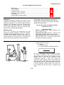
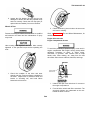
Personnel working on wheels and
tires must be qualified and trained to
do wheel and tire maintenance or
injury may result.
Remove all jewelry such as rings, dog
tags, bracelets, etc. If jewelry
contacts battery terminal, a direct
short may result in instant heating of
tools, damage to equipment, and
injury or death to personnel.
Do not start engine or move truck
when anyone is under truck. Severe
injury or death could result.
Spilled hydraulic fluid is slippery.
Clean up spilled fluid immediately or
injury to personnel may result.
Hot engine oil can cause severe
bums and personal injury. Care
should be exercised when changing
oil filter and draining hot oil.
e
TM 10-3930-671-24
Starting fluids or aids such as ether
or gasoline must not be used in a
diesel engine air intake system. The
use of these fluids will cause severe
internal engine damage and/or bodily
injury.
• Stall tests must be performed with the
parking brake applied and wheels
blocked up above the ground surface
to prevent movement. Be careful that
the truck does not move unexpectedly
when operating the engine and
converter
at
stall.
Unexpected
movement of the truck could cause
injury or death to personnel.
The overhead guard and mounting is
not designed (stressed) to support
the weight of the lift truck. Attempting
to lift the truck using the overhead
guard may result in injury or death to
personnel.
• Do not run engine and converter at stall
longer than necessary to take the rpm
and vacuum readings, or longer than
30 seconds at one time. Then, shift
transmission into NEUTRAL for 15
seconds and run the engine at one-half
speed for 1-2 minutes to cool torque
converter oil. Excessive temperature
250°F (1200C) max will overheat the
converter and cause damage to
converter, seals, and fluid.
Be sure truck is parked and
positioned in a safe and convenient
manner or injury to personnel may
result.
Bodily injury may result during the
timing operation of the fuel injection
pump if the engine is running. DO
NOT attempt to adjust the timing
without the pump mounting bolts
securely torqued.
Do not operate a lift truck if the
service or parking brakes are not
operating properly.
Be sure transmission directional
control is in NEUTRAL and truck
prevented from moving when parking
brake is released or personal injury
may result.
Use care when removing or installing
snap and retaining rings. Snap and
retaining rings are under spring
tension and can act as projectiles
when released and could cause
severe eye injury.
Before performing any maintenance
work, check the truck for stable
condition on the blocking to prevent
injury to personnel and damage to
equipment.
f
TM 10-3930-671-24
Never continue to operate a truck that
has a steering system fault. Injury to
personnel may result.
Stop engine before checking battery
terminals or electrical connections.
Sparks or flames near a battery could
cause an explosion or fire. Battery
acid can cause corrosive burns.
Always wear eye protection. Use of
jumper cables or battery charging
should be done only as directed by
manufacturers’ safety instructions.
Do not operate a lift truck with
damaged or missing decals and
nameplates.
Replace
them
immediately. They contain important
information to prevent injury or
damage to equipment.
Bodily injury or death may result to
individuals during operation of an
engine within any enclosure not
adequately or properly ventilated.
Engine operation in any enclosure
requires
adequate
and
proper
ventilation to avoid asphyxiation or
other
interruption
of
normal
breathing. To supply sufficient air to
cool the engine, provide air to mix
with fuel and to carry away heated air
from the building.
Escaping fluid under pressure can
have sufficient force to penetrate the
skin, causing personal injury. Before
disconnecting lines, be sure to
relieve all pressure. Before applying
pressure to the system, be sure all
connections are tight and that lines,
pipes, and hoses are not damaged.
Use a piece of cardboard, rather than
hands, to search for leaks. If injured
by escaping fluid, get medical
attention at once.
An upright or carriage can move unexpectedly.
• Do not walk or stand under raised
forks.
For safety when checking or
removing
battery
connections,
always first disconnect the negative
battery cable at the engine ground
connection.
• Keep clear of load and carriage when
making any checks and adjustments.
• Keep your arms and fingers away from
moving parts of the upright. Do notg
reach through upright open areas.
To avoid the possibility of personal
injury, never work in engine
compartment with engine running
except when absolutely necessary to
check or adjust timing, carburetor, or
governor. Take extreme care to keep
hands, tools, loose clothing, etc.,
away from fan and drive belts. Also
remove watches, bracelets, and
rings.
• Failure to follow these warnings can
result in serious injury.
Always follow the manufacturer's instructions for the
test instrument being used when making
connections and tests on electrical circuits or
damage to equipment could occur.
g
TM 10-3930-671-24
Assemble/disassemble
hydraulic
pump only in a clean, dust free
location. Dirt or grit will damage
machined surfaces and result in
leakage or premature failure.
Be careful when sump is nearly
emptied.
Watch for signs of pump cavitation.
Do not operate pump after cavitation
occurs or damage to equipment may
result.
Never pour cold water or cold
antifreeze into the radiator of an
overheated engine. Allow the engine
to cool and avoid the danger of
cracking the cylinder head or block.
Keep engine running while adding
coolant.
Damage to the truck can result if any
of the warning indicators illuminate
when the engine is running. Stop the
engine. Do not operate the truck.
Report any failures.
If the oil pressure is erratic or falls
below these limits, stop the engine
IMMEDIATELY and find the cause of
the trouble or damage to equipment
could result. Refer to troubleshooting
section for this information.
Do not add oil until oil level
approaches the LOW mark. Then add
only enough to bring it to high levelNEVER above. Do not operate the
engine with oil level below the low
level mark, or damage to equipment
may result.
Be sure that the mounting bolts are
undamaged and have the correct
material (strength and hardness)
specification. Do not use substitute,
defective, or incorrect mounting
bolts. Replace worn or defective bolts
or damage to equipment could result.
Do not overfill crankcase with engine
oil, or serious damage may occur to
engine.
Be sure there is adequate overhead
clearance before raising the upright
or damage to equipment could result.
Be sure to secure the load to the fork
carriage to keep it from falling off
when tilted forward or damage to
equipment could result.
Be careful when inspecting or
replacing the air filter element to
prevent loose dirt from entering the
engine air intake housing or hose.
Damage to engine may result.
Have missing bolts replaced and
loose bolts correctly tightened to the
specified torque before operating the
truck or damage could result.
h
TM 10-3930-671-24
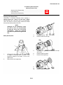
Never operate the starter motor more
than 30 seconds at a time without
pausing to allow it to cool for at least
2 minutes. Overheating caused by
excessive cranking will seriously
damage the starter motor.
When the transaxle is new or rebuilt,
it is recommended to change the oil
filter after the first 50 hours and again
after 100 operating hours. This is to
be sure that the oil is cleaned of all
harmful particles which may be
loosened or flushed off new parts as
they wear in. Failure to change the oil
filter may result in damage to
transaxle.
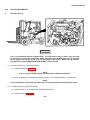
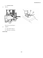
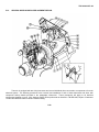
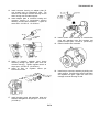
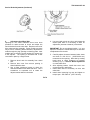
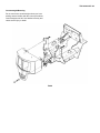
It is recommended that the engine be
removed only as a separate assembly
disconnected from the transaxle.
Generally,
because
of
height
(clearance) limitations, removal of the
engine and transaxle as a unit
requires extensive disassembly of the
front structure of the truck, including
removal of the dash and instrument
panel. It is much easier and simpler
to remove the engine by itself. Engine
removal is also made easier with less
chance of accidental damage to
components when the counterweight
and radiator are removed.
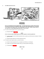
For safety and convenience, it is
recommended whenever possible to
use an overhead hoist to remove the
engine from the truck.
Use lifting hooks with safety latches
to prevent hook from slipping from
the lifting eye.
Whenever welding on this vehicle,
always disconnect battery cables. Do
not put ground strap on lift carriage
or mast unless welding on lift
carriage or mast.
Never allow cool water to come in
contact with the fuel injection pump
while the engine is running! Injection
pump seizure may result.
The transmission fluid must be at
operating temperature of 180-200°F
(82-930C) to obtain correct fluid level
and pressure readings. Do not
attempt to make these checks with
cold oil.
Always
cover
openings
with
protective caps at any time when
lines are disconnected.
This will
prevent any dirt or foreign matter
from entering.
Under no circumstances should the
engine be allowed to operate at a
higher speed than is specified.
Severe damage to the engine may
result.
j
TM 10-3930-671-24
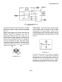
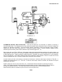
should be checked with a voltmeter
before
connecting
the
battery.
Reversed battery connections may
damage the rectifiers, wiring or other
components of the charging system.
• The field circuit must never be
grounded on this system, between the
alternator and the regulator. Grounding
of the field terminal either at the
alternator or regulator will damage the
regulator.
• If it is necessary to solder any lead to a
rectifier lead, use a pair of pliers as a
heat dam between the solder joint and
the rectifier or damage to the rectifier
may result.
• Do not ground the output terminal.
Grounding of the alternator output
terminal may damage the alternator
and/ or circuit and components.
• Keep serviceable bearing cups and
cones matched together. Always
replace bearing cups and cones as a
set or damage to equipment may result.
• Do not connect battery to the regulator
field terminal or damage to the
regulator will result.
• Do not attempt to polarize the
alternator. No polarization is required.
Any attempt to do so may result in
damage to the alternator, regulator, or
circuits.
• Be sure the parking brake is applied
and blocks put at the front and rear of
drive wheels or damage to equipment
may result.
• Be sure the alternator and battery have
the same ground polarity. Battery
polarity
k
TM 10-3930-671-24
TECHNICAL MANUAL
HEADQUARTERS
DEPARTMENT OF THE ARMY
Washington, DC, 1 May 1996
No. 10-3930-671-24
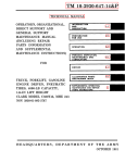
TECHNICAL MANUAL
ORGANIZATIONAL, DIRECT SUPPORT,
AND GENERAL SUPPORT
MAINTENANCE MANUAL
TRUCK, FORKUFT, CLEAN BURN
DIESEL, FRONT-LOADING,
4000 LB. CAPACITY, M483
CLARK MODEL GPX 25E DIESEL
NSN 3930-01384-5310
REPORTING OF ERRORS
You can help improve this manual. If you find any mistakes or if you know of a way to
improve the procedures, please let us know. Mail your letter, DA Form 2028
(Recommended Changes to Publications and Blank Forms) or DA Form 2028-2 located
in the back of this manual direct to: Commander, US Army Tank-automotive and
Armaments Command, ATTN: AMSTA-IM-OPIT, Warren, Ml 48397-5000. A reply will be
furnished to you. You may also provide DA Form 2028-2 information to TACOM via
datafax or e-mail. TACOM’s datafax number for AMSTA-IM-OPIT is: (810) 574-6323 and
the e-mail address is: amstaim-mmaa @ cc.tacom.army. mil.
This manual is an authentication of the manufacturer’s commercial literature and does not
conform with the format and content specified in AR 25-30, Military Publications. This
technical manual does, however, contain available information that is essential to the
operation and maintenance of the equipment.
Approved for public release; distribution is unlimited.
i (ii blank)
TM 10-3930-671-24
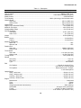
TABLE OF CONTENTS
Chap/Para
Title
Page
LIST OF ILLUSTRATIONS.............................. vii
LIST OF TABLES ............................................ vii
Chap/Para
3-12
3-13
3-14
3-15
SAFETY SUMMARY........................................viii
General Precautions ....................................... viii
General Safety Practices ................................ viii
Safety Suggestions for Operating Truck .......... ix
Safety Suggestions for Servicing Truck ... ....... ix
1
INTRODUCTION AND GENERAL
INFORMATION ..................................1-1
1-1
1-2
1-3
1-4
1-5
1-6
Introduction ........................................1-1
Capabilities ........................................1-1
Description ........................................1-1
Performance Characteristics ..............1-6
Environmental Information ............... 1-6
Maintenance Forms, Records, ................
and Reports .......................................1-6
Destruction of Army Material ...................
to Prevent Enemy Use .......................1-6
Reporting Equipment Improvement ........
Recommendation (EIR) .....................1-6
Tools and Test Equipment ................1-6
Shipping and Handling Instructions ...1-6
Storage Data .................................... 1-6
1-7
1-8
1-9
1-10
1-11
2
ORGANIZATIONAL ................................
TROUBLESHOOTING.......................2-1
2-1
2-2
2-3
Troubleshooting Introduction ............ 2-1
Troubleshooting Symptoms .............. 2-1
Unit Troubleshooting Procedures ..... 2-1
3
ORGANIZATIONAL
MAINTENANCE.................................3-1
Maintenance Introduction ................. 3-1
General Removal Instructions .......... 3-1
General Disassembly Instructions .... 3-1
General Cleaning Instructions ...........3-2
General Inspection Instructions ........ 3-3
General Repair Instructions .............. 3-4
General Assembly and Installation
Instructions ........................................3-5
PMCS Introductory Material ..............3-6
Maintenance Forms and Records .....3-6
General PMCS Procedures and
Conditions ..........................................3-6
Fluid Leakage Definition ....................3-8
3-1
3-2
3-3
3-4
3-5
3-6
3-7
3-8
3-9
3-10
3-11
3-16
3-17
3-18
3-19
3-20
3-21
3-22
3-23
3-24
3-25
3-26
3-27
3-28
3-29
3-30
3-31
3-32
3-33
3-34
3-35
3-36
3-37
3-38
Title
Page
PMCS Table Description ........................................3-8
Torque Limits .......................................................3-12
Oil Sampling Valve Replacement .........................3-16
Engine Oil Breather Cap Assembly
Replacement ..............................................3-20
Fuel System Service ............................................3-21
Fuel System Repair ..............................................3-23
Air Intake System Replacement ...........................3-39
Exhaust System Replacement .............................3-42
Alternator Replacement ........................................3-44
Regulator Replacement ........................................3-45
Electrical Component Replacement .....................3-47
Directional Control Switch Assembly
Replacement ..............................................3-66
Flood and Stop Light
Replacement/Repair ...................................3-67
Battery Replacement ............................................3-71
Battery Cable Replacement .................................3-74
Battery Cable Service ...........................................3-76
Parking Brake Lever Replacement ......................3-78
Brake System Repair ...........................................3-79
General Hydraulic Hose Replacement .................3-84
General Hydraulic Piping
Replacement ..............................................3-88
Hydraulic Reservoir Replacement ........................3-90
Hydraulic Oil Filter Base Assembly
Repair .........................................................3-92
Lifting Eye and Tiedown
Replacement ....................................................... 3-94
Overhead Guard Replacement ............................3-95
Body Panel Replacement .................................... 3-97
Seat Assembly
Replacement/Repair..................................3-109
Insulation Replacement.......................................3-112
4
DIRECT SUPPORT/GENERAL SUPPORT
TROUBLESHOOTING .................................4-1
4-1
4-2
4-3
Troubleshooting Introduction ..................................4-1
Troubleshooting Symptoms ...................................4-1
DS/GS Troubleshooting Procedures ......................4-1
5
DIRECT SUPPORT/GENERAL SUPPORT
MAINTENANCE............................................5-1
5-1
5-2
5-3
5-4
5-5
5-6
Maintenance Introduction .......................................5-1
General Removal Instructions ................................5-1
General Disassembly Instructions .........................5-1
General Cleaning Instructions ................................5-2
General Inspection Instructions .............................5-3
General Repair Instructions ...................................5-4
iii
TM 10-3930-671-24
TABLE OF CONTENTS
Chap/Para
5-7
5-8
5-9
5-10
5-11
5-12
5-13
5-14
5-15
5-16
5-17
5-18
5-19
5-20
5-21
5-22
5-23
5-24
5-25
5-26
5-27
5-28
A
A-1
A-2
A-3
A-4
B
Title
Page
General Assembly and Installation
Instructions ....................................... 5-5
PMCS Introductory Material .................. 5-6
Maintenance Forms and Records ......... 5-6
Fluid Leakage Definition ........................ 5-6
Torque Limits ......................................... 5-7
Engine Balancer Repair ....................... 5-11
Rear Endplate Replacement ............... 5-15
Starter Adapter Plate Replacement ..... 5-16
Rocker Arm Replacement ................... 5-17
Oil Filter Adapter Replacement ........... 5-19
Manifold Replacement ......................... 5-20
Fuel Injector Line Replacement ........... 5-22
Fuel Injector Pump Cover Repair ........ 5-24
Starter Motor Repair ............................ 5-26
General Wire Harness .................................
Replacement/Repair ...................... 5-30
Main Frame Inspection......................... 5-36
Hydraulic Pump Repair ........................ 5-37
Carriage Assembly Repair .................. 5-42
Roller Sheave Repair .......................... 5-47
Lift Cylinder Replacement/Repair ........ 5-49
Side Shift Cylinder Repair ................... 5-57
Upright Repair ..................................... 5-59
REFERENCES ...................................... A-1
......................................................................
Scope .................................................... A-1
Publication Index ................................... A-1
Forms ..................................................... A-1
Other Publications ................................. A-1
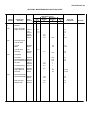
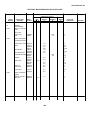
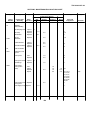
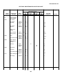
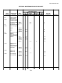
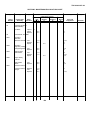
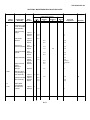
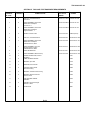
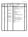
MAINTENANCE ALLOCATION ..................
CHART (MAC) ................................ B-1
SECTION I. INTRODUCTION ............... B-1
B-1
B-2
B-3
B-4
General................................................... B-1
Maintenance Functions ......................... B-1
Explanation of Columns in Section II..... B-2
Explanations of Columns in Tools
and Test Equipment Requirements, ......
Section III ........................................ B-3
SECTION II. MAINTENANCE
ALLOCATION CHART ................... B-4
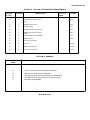
SECTION III. TOOLS AND TEST
EQUIPMENT REQUIREMENTS .......... B-18
SECTION IV. REMARKS .................... B-19
Chap/Para
Title
Page
C
EXPENDABLE/DURABLE SUPPLIES
AND MATERIALS LIST .......................... C-1
C-1
C-2
Scope .................................................................. C-1
General ......................................... ..................... C-1
D
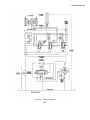
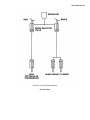
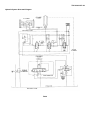
SCHEMATICS AND DIAGRAMS ....................... D-1
D-1
Introduction ....................................................... D-1
E
LUBRICATION ORDER ......................................E-1
E-1
General Lubrication Instructions .........................E-1
F
COMMERCIAL PLANNED
MAINTENANCE
AND ADJUSTMENTS ..............................F-1
1.0
GENERAL INFORMATION ................................F-7
2.0
SPECIFICATIONS ............................................F-17
3.0
PLANNED MAINTENANCE ..............................F-35
3.1
3.2
3.3
PM Schedules ...................................................F-37
Planned Maintenance Procedures ................... F-41
Machine Jacking and Blocking ..........................F-59
4.0
ENGINE .............................................................F-63
4.1
4.2
4.3
4.4
4.5
4.6
4.7
4.8
4.9
4.10
4.11
4.12
4.13
4.14
Engine Maintenance .........................................F-65
Engine Troubleshooting ....................................F-67
Engine Tune-Up ................................................F-73
Deleted
Engine Valve Clearance Adjustment .................F-79
Engine Compression Pressure Test .................F-83
Engine RPM & Stall Tests .................................F-87
Cooling System .................................................F-93
Engine Air Cleaner ..........................................F-103
Engine Adjustments ........................................F-107
Engine Removal ..............................................F-111
Deleted
Engine Components ........................................F-119
Continental Diesel Engine................................F-125
5.0
FUEL SYSTEM ...............................................F-195
5.1
5.2
Fuel Systems Maintenance..............................F-197
Deleted
iv
TM 10-3930-671-24
TABLE OF CONTENTS
Chap/Para
Title
Page
Chap/Para
Title
Page
5.3
5.4
5.5
5.6
5.7
5.8
5.9
5.10
5.11
Diesel Fuel Injection System ......... F-199
Deleted
Deleted
Deleted
Deleted
Deleted
Deleted
Deleted
Fuel Injection Pump ...................... F-209
8.0
BRAKES ..........................................................F-381
8.1
8.2
8.3
8.4
8.5
Service Brake & Inching Systems ...................F-383
Deleted
Deleted
Brake & Inching System...................................F-385
Brake Bleeding.................................................F-395
9.0
STEERING SYSTEM .......................................F-401
6.0
ELECTRICAL SYSTEM................ F-255
9.1
6.1
6.2
6.3
6.4
6.5
6.6
6.7
6.8
6.9
9.2
9.3
6.10
6.11
6.12
6.13
6.14
6.15
6.16
Electrical System Wiring ............... F-257
Deleted
Deleted
Deleted
Deleted
Deleted
Deleted
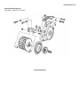
Alternator Maintenance ................ F-261
Prestolite Alternator
Service Manual ...................... F-267
Deleted ....................................................
Starting System Troubleshooting . F-297
Starter Motor Troubleshooting ..... F-307
Deleted
Deleted
Deleted
Starter Maintenance ..................... F-311
9.8
9.9
9.10
9.11
9.12
9.13
Power Steering SystemRelief Pressure Setting ...................................F-403
Steering Column and Valve .............................F-405
Steering ColumnRemoval/Installation ........................................F-407
Steering Valve Overhaul .................................F-413
Steer Axles ......................................................F-419
Steer AxleWheel Bearing Maintenance ...........................F-421
Steer AxleRemoval/Installation ........................................F-425
Deleted
Deleted
Deleted
Deleted
Steer Axle Overhaul ........................................F-431
Steering Cylinder Overhaul .............................F-441
10.0
HYDRAULIC SYSTEM ...................................F-445
7.0
TRANSAXLE................................. F-317
10.1
7.1
7.2
7.3
7.4
Transaxle Maintenance ................ F-319
Transmission Troubleshooting ..... F-323
Transmission Pressure Checks ... F-327
Transaxle Mounting
Removal/Installation ..................... F-329
Transaxle Overhaul-................................
General Procedures ............... F-341
TA18 Transaxle ............................. F-345
Deleted
Deleted
Deleted
Deleted
Deleted
Directional Control Linkage .......... F-379
10.2
10.3
10.4
10.5
10.6
10.7
Hydraulic SumpFluid and Filter Change
F-449
Hydraulic System Relief Pressure
Check & Adjustment .......................................F-455
Main Hydraulic Pump ......................................F-457
Deleted
Main Hydraulic Valve .......................................F-459
Main Hydraulic Valve Overhaul .......................F-465
Tilt Cylinder Maintenance ................................F-471
11.0
WHEEL & TIRES .............................................F-481
11.1
11.2
Tire and Wheel Maintenance ..........................F-483
Deleted
7.5
7.6
7.7
7.8
7.9
7.10
7.11
7.12
9.4
9.5
9.6
9.7
v
TM 10-3930-671-24
TABLE OF CONTENTS-CONTINUED
Chap/Para
Title
Page
Chap/Para
Title
Page
12.0
COUNTERWEIGHT & CHASSIS.. F-485
13.3
Triple Stage Upright ........................................F-507
12.1
12.2
Counterweight Maintenance ......... F-487
Deleted
14.0
INDEX .............................................................F-513
14.1
Section Contents Index ...................................F-514
Subject Index ... ...............................................F-526
13.0
UPRIGHT MAINTENANCE........... F-495
14.2
13.1
13.2
Upright Maintenance .................... F-497
Deleted
ALPHABETICAL INDEX............................................ Index-1
vi
TM 10-3930-671-24
LIST OF ILLUSTRATIONS
Figure
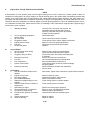
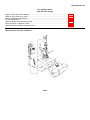
1-1
Title
Page
Figure
M483 4K Forklift Truck - Left Front
View (Sheet 1 of 2) ............................1-2
1-1
Title
Page
M483 4K Forklift Truck - Right Rear
View (Sheet 2 of 2) .............................................. 1-3
LIST OF TABLES
Table
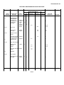
1-1
2-1
2-2
3-1
3-2
3-3
3-4
3-5
Title
Page
Description ............................................ 1-4
Unit Troubleshooting Symptom Index ... 2-1
Unit Troubleshooting Procedures .......... 2-2
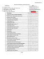
Unit Preventive Maintenance Checks ..........
and Services ................................... 3-9
U.S. Standard Torque Values (Wet) ... 3-12
U.S. Standard Torque Values .....................
(Dry Fasteners) ............................. 3-13
Metric Torque Values (Dry Fasteners). 3-14
Metric Torque Values (Phosphate ...............
Coated Engine Fasteners) .................. 3-14
Table
3-6
4-1
4-2
5-1
5-2
5-3
5-4
5-5
vii
Title
Page
Critical Fastener Torque Values (Dry) ............... 3-15
DS/GS Troubleshooting Symptom
Index ........................................................... 4-1
DS/GS Troubleshooting Procedures ................... 4-2
U.S. Standard Torque Values (Wet) ................... 5-7
U.S. Standard Torque Values
(Dry Fasteners) ........................................... 5-8
Metric Torque Values (Dry Fasteners) ................ 5-9
Metric Torque Values (Phosphate
Coated Engine Fasteners) .................................. 5-9
Critical Fastener Torque Values (Dry) ............... 5-10
TM 10-3930-671-24
SAFETY SUMMARY
GENERAL PRECAUTIONS
The following are general safety precautions and
instructions that personnel must understand and apply
during many phases of operation and maintenance to
ensure personnel safety and health. Portions of this
information may be repeated in certain chapters of this
publication for emphasis.
GENERAL SAFETY PRACTICES
Read and thoroughly understand all instructions
contained in this and all vendor manuals before
attempting to operate or service the 4K Forklift Truck.
Only the operator is allowed on the truck during
operation.
Cleaners/Chemicals Handling
Clothing worn by all personnel working close to the truck
should be close fitting and belted. Loose jackets, shirts,
or pants should never be worn because of the danger of
getting caught in moving parts.
Keep cleaners/chemicals in approved safety containers
and in minimum quantities. Some cleaners/ chemicals
may have an adverse effect on skin, eyes and respiratory
tract. Observe manufacturer’s WARNING
labels
and
current
safety
directives.
Use
cleaners/chemicals only in authorized areas. Consult the
local Bioenvironmental Engineer for specific precautions,
protective equipment, and ventilation requirements.
Be certain that hand brake is set and the direction speed
control levers and all switches are in the OFF or
centered positions before starting the engine.
Make sure everyone is clear of the truck before starting
so they cannot be struck by or caught in moving parts.
Compressed Air
Use of compressed air can create an environment of
propelled foreign particles. Air pressure shall be reduced
to less than 30 pounds-per-square-inch gauged (psig)
and used with effective chip guarding and personal
protective equipment.
Keep operator’s platform clean. Do not use it as a place
to carry loose tools, lunch boxes, etc.
Refuel truck only when engine has been shut off. Do not
permit sparks, open flames or smoking within 50 feet of
truck when refueling.
Batteries
When inspecting batteries, never smoke or expose
battery to sparks of flames. Eye protection (face shield),
acid resistant rubber apron and gloves must be worn
when working around batteries.
Escaping hydraulic fluid under pressure can have
sufficient force to penetrate the skin, causing serious
personal injury. Before disconnecting lines, be sure to
relieve all pressure. Before applying pressure to a
system, be sure all connections are tight and that lines,
tubes, and hoses are not damaged. Fluid escaping from
a very small hole can be almost invisible. Use a piece of
cardboard or wood, rather than hands, to search for
suspected leaks.
Jewelry
Jewelry (rings, bracelets, metal watches, or neck chains)
shall not be worn while working on exposed equipment.
Personal Protective Equipment
Wear protective clothing/equipment (gloves, apron, eye
protection, protective mask, etc.) approved for the
materials, procedures and tools being used as
necessary.
If injured by escaping fluid, get medical attention at once.
Serious infection or reaction can result if proper medical
treatment is not administered immediately.
viii
TM 10-3930-671-24
SAFETY SUMMARY - Cont.
Refill the radiator only when the engine is stopped. The
truck has a pressure cooling system. To avoid being
scalded when radiator cap is removed, first turn cap
slightly to the stop which allows steam to escape through
the overflow pipe. After all pressure is relieved, remove
cap.
Never lubricate or service truck when it is operating.
SAFETY SUGGESTIONS FOR OPERATING TRUCK
Be sure all hoods and doors are closed before operating
truck.
Be certain the direction/range control levers are in
NEUTRAL positions before starting engine.
Check all functions of the truck for proper operation.
Never attempt to use a malfunctioning machine.
SAFETY SUGGESTIONS FOR SERVICING TRUCK
Before attempting to service, attach, or remove any part
of assembly on the truck, make certain that:
(1) All controls and switches are in the OFF or centered
position.
(2) Hand brake is applied.
(3) Forks are lowered.
(4) Engine is shut off unless otherwise instructed.
Batteries produce explosive gases. Keep all sparks and
open flames away from batteries. If a battery needs
recharging, avoid sparks by turning off the charger
before making connections or disconnections.
Sulfuric acid in batteries is a poison and could cause
severe burns. Avoid contact with skin, eyes, and clothing.
When working around batteries, protect eyes and face
from battery fluid and possible explosion.
Never permit anyone to climb or stand on the truck.
Keep all persons clear of forks when operating truck.
Before leaving the operator’s seat always be sure that all
control switches are in the OFF or centered position,
hand brake is applied, forks are lowered, and engine is
shut off.
Before starting the engine, be sure there is plenty of
ventilation. If it is necessary to operate the engine inside
an enclosed service area, be sure exhaust is properly
vented.
Make sure everyone is clear of the truck before starting
so they cannot be struck by or caught in moving parts.
Never attempt to attach or remove any part or assembly
on the truck while it is operating.
ix (x blank)
TM 10-3930-671-24
CHAPTER 1
INTRODUCTION & GENERAL INFORMATION
1-1.
c. WARNINGS, CAUTIONS, and NOTES.
Warnings, cautions, and notes used in this manual are
defined as:
INTRODUCTION.
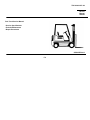
a. Purpose of This Manual. This is a
supplemental manual designed to provide information
concerning troubleshooting and maintenance at the
Organizational, Direct Support, and General Support
levels not already covered in vendor manuals for the
M483, 4000 lb Forklift Truck, hereafter referred to as the
truck, manufactured by Clark Material Handling
Company, Lexington, KY, model GPX 25E Diesel (See
Figure 1-1). This manual contains the following:
(1) A “warning” identifies an operation or
maintenance procedure, practice, condition, statement,
etc., which, if not strictly observed, could result in
damage to, or destruction of, equipment, and/or injury or
loss of life.
(2) A “caution" identifies an operation or
maintenance procedure, practice, condition, statement,
etc., which, if not strictly observed, could result in
damage to, or destruction of, equipment or loss of
mission effectiveness.
(1) Chapter 1 Introduction and
General Information: General information about the
makeup of this manual, including a general description of
the truck and specifications table, are presented in this
chapter.
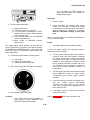
(3) A “note” highlights an essential operation or
maintenance procedure, condition, or statement.
(2)
Chapter
2
Organizational
Troubleshooting: Instructions for troubleshooting at the
organizational level are presented in this chapter.
1-2.
(3)
Chapter
3
Organizational
Maintenance:
Instructions
for
performance
of
maintenance procedures at the Organizational level are
presented in this chapter.
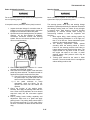
The truck is a 4-wheeled piece of material handling
equipment capable of lifting palletized and certain loose
loads, when appropriate, up to a maximum weight of
4000 lb (1814.4 kg). Over smooth and level surfaces, the
truck can reach a maximum speed of 12 mph (19.3 kph)
unloaded and 11.3 mph (18.1 kph) with a full load when
safety conditions merit.
(4) Chapter 4 Direct Support/General
Support
Troubleshooting:
Instructions
for
troubleshooting at the Direct Support/General Support
level are provided in this chapter.
1-3.
CAPABILITIES.
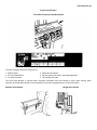
DESCRIPTION.
Single, solid rubber wheels in front of truck provide
stability and ruggedness. Safety equipment consists of
an automotive horn operable from steering wheel. Two
floodlights on the overhead guard help illuminate the
area in front of the truck while two floodlights in the back
of the overhead guard illuminate the area behind truck. A
brake light at the back of truck illuminates whenever
brake or inching pedal is depressed.
(5) Chapter 5 Direct Support/General
Support Maintenance: Instructions for maintenance
procedures at the Direct Support/General Support levels
are provided in this chapter.
(6)
Appendices:
Instructions
for
lubrication and Army-specific and vendor-specific
information are arranged as appendices.
b. Function of This Manual. This manual
provides instructions, illustrations, and associated data
for maintenance and repairs. This manual shall enable
an average journeyman to maintain and repair the truck.
1-1
TM 10-3930-671-24
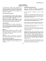
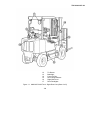
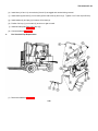
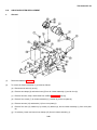
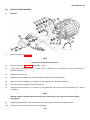
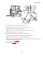
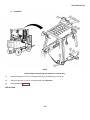
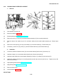
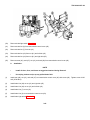
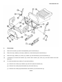
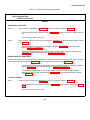
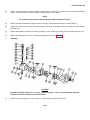
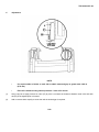
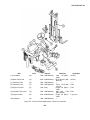
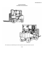
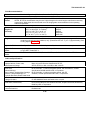
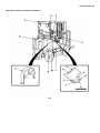
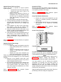
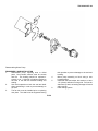
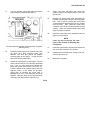
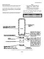
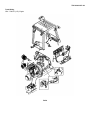
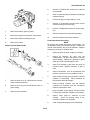
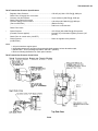
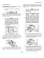
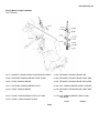
1.
2.
3.
4.
5.
6.
7.
8.
9.
10.
11.
Mast Assembly
Front Floodlights
Carriage Assembly
Forks
Front Wheels
Rear Wheels
Counterweight
Left-Side Hood
Operator’s Seat
Top Hood
Overhead Guard
Figure 1-1. M483 4K Forklift Truck - Left Front View (Sheet 1 of 2)
1-2
TM 10-3930-671-24
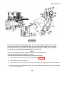
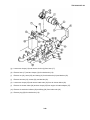
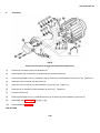
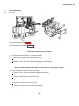
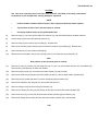
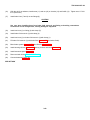
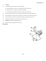
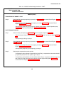
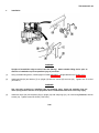
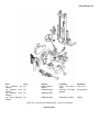
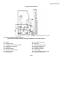
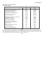
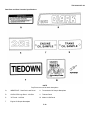
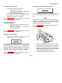
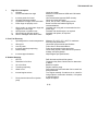
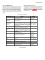
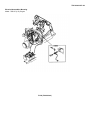
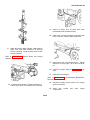
12.
13.
14.
15.
16.
17.
Tie Downs
Brakelight
Front Lift Point
Rear Lifting Brackets
Right-Side Hood
Rear Floodlights
Figure 1-1. M483 4K Forklift Truck - Right Rear View (Sheet 2 of 2)
1-3
TM 10-3930-671-24
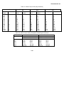
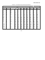
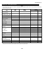
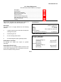
Table 1-1. Description
Nomenclature
Description
Type of Vehicle ............................................................................................................................... 4000 lb Forklift Truck
Manufacturer ............................................................................................................. Clark Material Handling Company
Model Number ........................................................................................................................................ GPX 25E Diesel
Truck Capacity ..................................................................................................000 lb (1814.4 kg) 0 24-inch load center
Overall Length
With Forks ..................................................................................... ........................................144.9 in (3680 mm)
Without Forks ................................................................................ ........................................102.9 in (2614 mm)
Overall Width ....................................................................................................................................... 82.7 in (2101 mm)
Height (Top of Overhead Guard) ............................................................................................................ 83 in (2108 mm)
Maximum Lift Height ............................................................................................................................. 184 in (4674 mm)
Collapsed Mast Height .................................. ......................................................................................... 83 in (2108 mm)
Ground Clearance
Under Mast ............................................................................................................................... 6.25 in (159 mm)
Under Truck ................................................................................................................................... 8 in (203 mm)
Weight .................................................................................................................................................. 9735 lb (8952 kg)
Brakes
Service............................................................................................................................................2-wheel Drum
Parking ...........................................................................................................................................2-wheel Drum
Maximum Gradeability
With Load ..................................................................................................................................................... 24%
Without Load ................................................................................................................................................ 25%
Drawbar Pull
With Load ........................................ ..................................................................................... 12030 lb (53512 N)
Without Load ........................................ .................................................................................. 7670 lb (34118 N)
Travel Speed
With Load ............................................................................................................................ 11.3 mph (18.1 kph)
Without Load .......................................................................................................................... 12 mph (19.3 kph)
Turning Radius ..................................................................................................................................... 134 in (3404 mm)
Wheels
Size (front) ............................................................................................................................................. 7.00 x 12
Size (rear) ............................................................................................................................................. 6.50 x 10
Type .................................................................................................................................................Solid Rubber
Drift
Lift Cylinders ...............................................................................................................Should not exceed 0.73 in
(18.5 mm) in a 5-minute period
Tilt Cylinders ........................................................................................................ Should not exceed 1.5 degree
in a 5-minute period
Upright Speed
Lifting - With Load ......................................................................................................................80 fpm (.41 m/s)
Lifting - Without Load .................................................................................................................87 fpm (.44 m/s)
Lowering - With Load .................................................................................................................69 fpm (.35 m/s)
Lowering - Without Load ............................................................................................................79 fpm (.40 m/s)
Engine
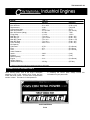
Manufacturer ...................... ................................................................................................................Continental
Type............................................................................................................................................................ Diesel
Model ...................................................................................................................................................... TMD 27
Weight (approximate w/accessories) .......................................................................................... 568 lb (258 kg)
Horsepower ............................................................................................................ 60 hp (44.1 kW) 0 3100 rpm
Torque ........................................ .......................................................................119 Ib-ft (161 Nom) 0 1600 rpm
Bore/Stroke ................................................................................................... 3.58 in/4.06 in (91 mm/103.1 mm)
1-4
TM 10-3930-671-24
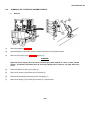
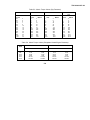
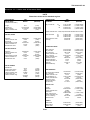
Table 1-1. Description-CONT
Nomenclature
Description
Engine - continued
Displacement ........................................................................................................................... 164 cu in (2.68 I)
Firing Order ............................................................................................................................................. 1-3-4-2
Compression Ratio .................................................................................................................................... 20.5:1
Speed
Governed Speed (no load) ............................................... .......................................................... 2600 rpm
Engine Idle .................................................................................................................................... 650 rpm
Oil Pressure ........................................................................................................... 40-60 psi (276-414 kPa) with
oil at operating temperature
Lubricant .............................................................................................................................................SAE 5W30
Fuel ......................................................................................................................................45 cetane, minimum
Coolant ...................................................................................................................50/50 Water/Ethylene Glycol
type antifreeze with rust and corrosion inhibitors
Drive Belt
Type ........................................................................................................................................................... V-belt
Deflection ......................................................................................................................... 20 in (5.1 mm) in long
span at 2.5-3.2 Ibft (3.4-4.3 N) at center
of alternator-crankshaft-pulley
System Voltage ......................................................................................................................... 12-volt, negative ground
Altemator ................................................................................................................................................ 12-volt, 62 amp
Batteries (2)
Type .............................................................................................................................................. BCI Group 4D
Cold Crank Current ..................................................................................................... 625 amps at 0°F (-180C)
Reserve Capacity ............................................................................................. 310 amps min at 80°F (26.7°C)
Starter ................................................................................................................... TMD27M506 (Nippondenso), 12-volt
Transaxle
Manufacturer ...............................................................................................................................................Clark
Type ...................................................................................................................... 1-speed forward and reverse
Model .......................................................................................................................................................... TA18
Weight ......................................................................................................................................... 600 lbs (272k)
Hydraulic System
Filter Size ............................................................................................................................................ 10 micron
Main Relief Valve Setting ........................................................... 2600-2700 psi (17927-18616 kPa), adjustable
Pump Pressure .......................................................................... 11.7 gpm (44.3 I/min) @ 3000 psi (20685 kPa)
@ 1800 rpm @ operating temperature
Side Shifter Relief Valve Setting ....................................... 1925-2075 psi (13270-14307 kPa), adjustable
Steering System
Pressure ........................................................................................ 4gpm (15.14 I/min) @ 3000 psi (10685 kPa)
@ 1800 rpm 0 operating temperature
Relief Pressure Setting .............................................................................. 1200-1300 psi (8274 - 8964 kPa), adjustable
Capacities
Crankcase
With Filter ........................................ ..............................................................................................................5.5 qt (52 1)
Without Filter ........................................ .........................................................................................................5 qt (4.73 1)
Cooling System ........................................ ..........................................................................................9 qt (8.5 1)
Fuel ..................................................................................................................................................... 8 gal (30 I)
Transaxle (Transmission & Drive Axle) ...........................................................................................16 qt (15.1 I)
Hydraulic Tank .............................................................................................................................. 5.5 gal (20.8 I)
1-5
TM 10-3930-671-24
1-4.
PERFORMANCE CHARACTERISTICS.
1-8.
REPORTING EQUIPMENT
RECOMMENDATION (EIR).
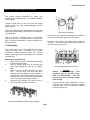
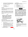
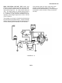
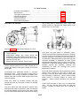
a. Engine. The truck is powered by a
Continental water-cooled, 4-cylinder, in-line diesel
engine. Model TMD 27 has 164 cubic inch (2.68 I)
displacement which develops 60 hp at 3100 rpm.
If your 4000 lb truck needs improvement, let us know.
Send us an EIR. You, the user, are the only one who can
tell us what you don’t like about our equipment. Let us
know why you don’t like the design. Put it on an SF 368
(Quality Deficiency Report). Mail it to us at Commander,
U.S. Army Tank-Automotive Command, ATTN: AMSTAQRD, Warren, Michigan 48397-5000. We’ll send you a
reply
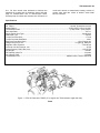
b. Transaxle. One-speed transaxle delivers
maximum torque, 100 Ib-ft at converter stall in both
forward and reverse.
c. Upright. Three-stage upright allows loads up
to 4000 lbs (1814.4 kg) to be lifted to a maximum height
of 184 inches (4674 mm). Hydraulic tilt capability allows
a maximum arc of 2.5 + .5 degrees forward tilt and 6
degrees reverse tilt.
1-9.
1-10.
The truck has sound suppression, air cleaner with
replaceable
element,
and
replaceable
engine,
transmission, and hydraulic oil filters.
FORMS,
RECORDS,
SHIPPING AND HANDLING INSTRUCTIONS.
a. Preparing For Shipment. Refer to TB 92300281-35 for procedures covering preservation of
equipment for shipment. General procedures for
shipment are found in FM 55-15. Specific information
may be found in TM 55-2200-001-12 for rail transport
and TB 55-45 for air transport.
ENVIRONMENTAL INFORMATION.
1-6.
MAINTENANCE
REPORTS.
TOOLS AND TEST EQUIPMENT.
All special tools or test equipment required to maintain
the truck in operation are listed in Appendix B.
d. Lifting Forks. Width between forks is
manually adjustable from 0 to 40 inches (0-1016 mm).
Forks can be hydraulically shifted left or right, in tandem,
3.9 inches (99 mm) each way for a total distance of 7.8
inches (198.1 mm).
1-5.
IMPROVEMENT
b. Administrative Storage. Refer to TM 740-90-1
for instructions covering administrative storage of
equipment.
AND
c.
Weight
Classification.
The
classification of the truck is 4000 lb (1814.4 kg).
Department of the Army forms and procedures used for
equipment maintenance will be those prescribed by DA
PAM 738-750, The Army maintenance management
System (TAMMS)(Maintenance Management UPDATE).
1-11.
weight
STORAGE DATA.
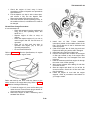
a. Short-Term Storage (30 days or less):
(1) Start engine and allow to warm up.
1-7.
DESTRUCTION OF ARMY MATERIAL TO
PREVENT ENEMY USE.
(2) Raise and lower forks fully several times.
Command decision, according to the tactical situation,
will determine when the destruction of the truck will be
accomplished. A destruction plan will be prepared by the
using organization unless one has been prepared by a
higher authority. For general destruction procedures for
this equipment, refer to TM 750-244-6, Procedures for
Destruction of Tank-Automotive Equipment to Prevent
Enemy Use (U.S. Army Tank-Automotive Command).
(3) Fully tilt upright forward and backward
several times.
(4) Coat all exposed, polished parts with rustpreventative lubricant.
1-6
TM 10-3930-671-24
(5) Extend all hydraulic cylinders, coat rods
with bearing grease, and then fully retract
cylinders.
(6) Clean truck thoroughly.
(7) Check truck thoroughly for worn or
damaged components and repair or
replace as required.
(8) Change engine oil and replace oil filter.
(9) Replace air cleaner element.
(10) Fill fuel tank with fuel and add inhibitor.
(11) Clean exterior of engine and coat with
rust-preventative lubricant.
(12) Lubricate entire truck per Lubrication
Order given in Appendix E.
(13) Park truck with forks fully lowered and
spread, upright tilted fully backward, and
carriage centered on upright.
(14) Seal
all
engine
openings
with
weatherproof tape.
(15) Engage parking brake.
b.
Long-Term Storage (Longer than 30 days)
(1) Perform all preventive maintenance
according to instructions given in Chapter
3.
(2) Start engine and allow to warm up.
(3) Raise and lower forks fully several times.
(4) Fully tilt upright forward and backward
several times.
(5) Extend all hydraulic cylinders, coat rods
with bearing grease, and then fully retract
cylinders.
(6) Check truck thoroughly for worn or
damaged components and repair or
replace as required.
1-7 (1-8 blank)
(7) Change engine oil and replace oil filter.
(8) Clean exterior of engine and coat with
rust-preventative lubricant.
(9) Replace air cleaner element.
(10) Fill fuel tank and add 3 ounces (90 ml) of
inhibitor to the fuel tank.
(11) Drain hydraulic reservoir, change main
hydraulic filters, and fill reservoir with
recommended fluid.
(12) Lubricate entire truck per Lubrication
Order given in Appendix E.
(13) Park truck with forks fully lowered and
spread, upright tilted fully backward, and
carriage centered on upright.
(14) Ensure that direction control levers are
centered (NEUTRAL).
(15) Engage parking brake.
(16) Remove and clean batteries. Store
batteries in a cool, dry place and keep
them fully charged.
(17) Disconnect air intake piping from the
manifold. Pour 3 ounces (90 ml) of
inhibitor into intake system and connect
the piping.
(18) Seal
all
engine
openings
with
weatherproof tape.
(19) Clean exterior of the truck and touch up
any scratched, chipped, or painted
surfaces.
(20) Coat all unpainted metal surfaces with
grease or corrosion inhibitor.
TM 10-3930-671-24
CHAPTER 2
ORGANIZATIONAL TROUBLESHOOTING
2-1.
TROUBLESHOOTING INTRODUCTION.
This section contains step-by-step procedures for identifying, locating, and isolating equipment malfunctions.
2-2.
TROUBLESHOOTING SYMPTOMS.
Table 2-1 lists the most common malfunctions found during operation of the truck. Tests or inspections and corrective
actions should be performed in the order listed. Table 2-2 lists corrective actions that can be performed by unit
maintenance. If a malfunction is not listed, or corrective action fails to correct a problem, notify DS/GS maintenance.
2-3.
UNIT TROUBLESHOOTING PROCEDURES.
Table 2-2 contains the malfunctions listed in Unit Troubleshooting Symptom Index (Table 2-1), test or inspection
instructions required to determine cause of malfunction, and corrective actions for repairing the faulty equipment. Operator
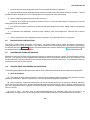
Troubleshooting Procedures (TM 10-3930-671-10) should be completed before performing Unit Troubleshooting
Procedures.
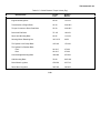
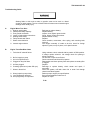
Table 2-1. Unit Troubleshooting Symptom Index
Troubleshooting Fault
Page
ENGINE
1.
Engine will not start ...........................................................................................................................
2.
Engine does not run evenly ...............................................................................................................
3.
A loss of power ..................................................................................................................................
4.
Engine temperature above normal ....................................................................................................
5.
Black exhaust smoke ........................................................................................................................
6.
White exhaust smoke ........................................................................................................................
7.
Truck slow to accelerate ....................................................................................................................
8.
Engine knocking ................................................................................................................................
2-3
2-4
2-5
2-6
2-7
2-8
2-8
2-9
HYDRAUUC SYSTEM
9.
10.
11.
12.
13.
14.
15.
16.
17.
18.
19.
20.
21.
22.
No lift, tilt, or sideshift function ...........................................................................................................
Load cannot be lifted to maximum height .........................................................................................
Oil leaks at top of lift cylinder(s) ........................................................................................................
Oil leaks at end of tilt cylinder(s) .......................................................................................................
Oil leaks at top or end of sideshift cylinder ........................................................................................
Upright lift speed sluggish .................................................................................................................
Pump not delivering hydraulic fluid ....................................................................................................
Pump not developing sufficient pressure ..........................................................................................
Noisy pump ........................................................................................................................................
Oil leaks at either end of main or auxiliary valve spool .....................................................................
Spring-centered spools do not return to neutral (main or auxiliary valve) .........................................
No motion, slow or jerky action of hydraulic system ..........................................................................
Load will not hold (downdrift) .............................................................................................................
Load drops when spool is moved from neutral to a power position ..................................................
2-1
2-9
2-9
2-10
2-10
2-10
2-10
2-11
2-12
2-12
2-13
2-13
2-13
2-14
2-14
TM 10-3930-671-24
Table 2-1. Unit Troubleshooting Symptom Index - CONT:
Troubleshooting Fault
Page
SERVICE BRAKE SYSTEM
23.
No brake pedal ............................................................................................................................................... 2-14
24.
Brake pedal spongy ........................................................................................................................................ 2-15
INCHING BRAKE SYSTEM
25.
No inching brake pedal ................................................................................................................................... 2-16
26.
Inching brake pedal spongy ............................................................................................................................ 2-16
STEERING SYSTEM
27.
No steering ..................................................................................................................................................... 2-17
28.
Hard steering .................................................................................................................................................. 2-18
TRANSMISSION
29.
Transmission will not operate in forward or reverse ....................................................................................... 2-18
30.
Transmission shifts slowly .............................................................................................................................. 2-19
31.
Transmission slips .......................................................................................................................................... 2-20
32.
Transmission lacks power .............................................................................................................................. 2-21
33.
Transmission overheats ................................................................................................................................. 2-21
ELECTRICAL SYSTEM
34.
Engine will not crank ....................................................................................................................................... 2-22
35.
Batteries will not hold a charge ....................................................................................................................... 2-24
36.
Gauges do not operate ................................................................................................................................... 2-25
37.
Cold start system does not operate ................................................................................................................ 2-25
38.
Horn does not operate .................................................................................................................................... 2-25
39.
One or more warning light does not operate .................................................................................................. 2-26
40.
Seat belt warning light does not operate ........................................................................................................ 2-26
41.
Seat belt buzzer does not operate .................................................................................................................. 2-27
42.
Taillight does not operate ............................................................................................................................... 2-27
43.
Brake light does not operate .......................................................................................................................... 2-27
44.
Front or rear floodlight(s) does not operate .................................................................................................... 2-28
2-2
TM 10-3930-671-24
Table 2-2. Unit Troubleshooting Procedures
MALFUNCTION
TEST OR INSPECTION
CORRECTIVE ACTION
ENGINE
1. ENGINE WILL NOT START.
Step 1. Check that engine is cranking.
If engine will not crank, go to step 2.
If engine will crank, go to step 3.
Step 2. Check if engine will turn over manually.
If engine will turn over manually, go to ELECTRICAL SYSTEM 34. ENGINE WILL NOT CRANK.
If engine will not turn over manually, notify DS/GS maintenance.
Step 3. Test fuel shutoff solenoid with key switch in RUN position.
If test result is not 5-11 volts, fuel injection pump faulty. Notify DS/GS maintenance.
If test result is 5-11 volts, go to step 4.
Step 4. Check if fuel lines and fittings are loose.
If fuel lines and/or fittings are loose, tighten or replace; then, bleed fuel system
(Appendix F, Fuel System, Section 5.0), and prime fuel system (Appendix F, Diesel
Fuel Injection System, Section 5.3).
If fuel lines and fittings are secure, go to step 5.
Step 5. Test fuel supply pressure at engine idle (650-700 rpm).
Disconnect fuel supply line at inlet side of fuel filter. Test fuel pressure. If test
results are not 1.50 to 2.25 psi, replace fuel supply pump (Para 3-17).
If test results are 1.50 to 2.25 psi, go to step 6.
Step 6. Test fuel filter pressure drop at engine idle (650-700 rpm).
Disconnect fuel supply line at outlet side of fuel filter. Test fuel pressure. If test
results are not 1.50 to 2.25 psi, replace fuel filter (Para 3-16).
If test results are 1.50 to 2.25 psi, notify DS/GS maintenance.
2-3
TM 10-3930-671-24
Table 2-2. Unit Troubleshooting Procedures - CONT.
MALFUNCTION
TEST OR INSPECTION
CORRECTIVE ACTION
ENGINE (CONT.)
2. ENGINE DOES NOT RUN EVENLY.
Step 1. Check if fuel lines and fittings are loose.
If fuel lines and/or fittings are loose, tighten or replace; then, bleed fuel system
(Appendix F, Fuel System, Section 5.0), and prime fuel system (Appendix F, Diesel
Fuel Injection System, Section 5.3).
If fuel lines and fittings are secure, go to step 2.
Step 2. Test fuel supply pressure at engine idle (650-700 rpm).
Disconnect fuel supply line at inlet side of fuel filter. Test fuel pressure. If test
results are not 1.50 to 2.25 psi, replace fuel supply pump (Para 3-17).
If test results are 1.50 to 2.25 psi, go to step 3.
Step 3. Test fuel filter pressure drop at engine idle (650-700 rpm).
Disconnect fuel supply line at outlet side of fuel filter. Test fuel pressure. If test
results are not 1.50 to 2.25 psi, replace fuel filter (Para 3-16).
If test results are 1.50 to 2.25 psi, go to step 4.
Step 4. Test fuel return pressure at engine idle (650-700 rpm).
Disconnect fuel return line at outlet side of fuel pump. Test fuel pressure. If test
results are not 2.4 psi (16 kPa), fuel line blockage is indicated. Remove and
replace fuel return lines (Para 3-17).
If test results 2.4 psi (16 kPa), go to step 5.
Step 5. Test coolant temperature after 10 minutes of operation.
If coolant temperature is above 217°F (102°C), proceed to 4. ENGINE TEMPERATURE ABOVE
NORMAL.
If coolant temperature is below 180°F (820C), remove and test thermostat (Appendix F, Cooling System, Section 4.8). Refer to Appendix F, Continental Diesel
Engine, Section 4.4, Section 4 to test thermostat. Replace thermostat as necessary.
If coolant temperature is normal, go to step 6.
2-4
TM 10-3930-671-24
Table 2-2. Unit Troubleshooting Procedures - CONT.
MALFUNCTION
TEST OR INSPECTION
CORRECTIVE ACTION
ENGINE (CONT.)
2.
ENGINE DOES NOT RUN EVENLY - CONT.
Step 6.
Test cylinder compression.
If all cylinders do not read between 325 - 400 psi, go to step 7.
If all cylinders read between 325 - 400 psi, go to step 8.
Step 7.
Check cylinder head valve clearance.
If cylinder head valves are out of adjustment, adjust valves (Appendix F, Engine Valve
Clearance Adjustment, Section 4.5).
If cylinder head valve clearances are OK, go to step 8.
Step 8.
Bleed fuel system (Appendix F, Fuel System, Section 5.0), and prime fuel system
(Appendix F, Diesel Fuel Injection System, Section 5.3).
If engine still does not run evenly, go to step 9.
Step 9.
Check that fuel type is correct type and not contaminated (W-F-800).
If fuel is incorrect type or contaminated, drain fuel tank and refill with correct/clean
fuel.
If fuel is OK, notify DS/GS maintenance.
3.
A LOSS OF POWER.
Step 1.
Check if fuel lines and fittings are loose.
If fuel lines and/or fittings are loose, tighten or replace; then, bleed fuel system
(Appendix F, Fuel System, Section 5.0), and prime fuel system (Appendix F, Diesel
Fuel Injection System, Section 5.3).
If fuel lines and fittings are secure, go to step 2.
Step 2.
Test fuel supply pressure at engine idle (650-700 rpm).
Disconnect fuel supply line at inlet side of fuel filter. Test fuel pressure. If test
results are not 1.50 to 2.25 psi, replace fuel supply pump (Para 3-17).
If test results are 1.50 to 2.25 psi, go to step 3.
2-5
TM 10-3930-671-24
Table 2-2. Unit Troubleshooting Procedures - CONT.
MALFUNCTION
TEST OR INSPECTION
CORRECTIVE ACTION
ENGINE (CONT.)
3.
A LOSS OF POWER - CONT.
Step 3.
Test fuel filter pressure drop at engine idle (650-700 rpm).
Disconnect fuel supply line at outlet side of fuel filter. Test fuel pressure. If test
results are not 1.50 to 2.25 psi, replace fuel filter (Para 3-16).
If test results are 1.50 to 2.25 psi, go to step 4.
Step 4.
Test coolant temperature after 10 minutes of operation.
If coolant temperature is above 217°F (102°C), proceed to 4. ENGINE TEMPERATURE ABOVE NORMAL.
If coolant temperature is below 180°F (820C), remove and test thermostat (Appendix F, Cooling System, Section 4.8). Refer to Appendix F, Continental Diesel
Engine, Section 4.4, Section 4 to test thermostat. Replace thermostat as necessary.
If coolant temperature is normal, go to step 5.
Step 5.
Check that fuel type is correct type and not contaminated (W-F-800).
If fuel is incorrect type or contaminated, drain fuel tank and refill with correct/clean
fuel.
If fuel is OK, notify DS/GS maintenance.
4.
ENGINE TEMPERATURE ABOVE NORMAL.
Step 1.
Check radiator for damage or debris that could restrict cooling capability.
WARNING
Compressed air used for cleaning purposes must not exceed regulated 30 psi (207 kPa).Use only
with effective chip guarding and personal protective equipment (goggles/shield, gloves, etc.) to
prevent injury to personnel.
If radiator is full of debris, use compressed air to blow debris out of radiator.
If radiator is damaged, or debris cannot be removed, replace radiator (Appendix F,
Engine Removal, Section 4.11).
If radiator is OK, go to step 2.
2-6
TM 10-3930-671-24
Table 2-2. Unit Troubleshooting Procedures - CONT.
MALFUNCTION
TEST OR INSPECTION
CORRECTIVE ACTION
ENGINE (CONT.)
4.
ENGINE TEMPERATURE ABOVE NORMAL - CONT.
Step 2.
Check fan belt adjustment.
If fan belt requires adjustment, adjust drive belt (Appendix F, Cooling System,
Section 4.8).
If fan belt is OK, go to step 3.
Step 3.
Check for faulty radiator cap (Appendix F, Cooling System, Section 4.8).
If radiator cap is faulty, replace radiator cap (Appendix F, Cooling System, Section
4.8).
If radiator cap is OK, go to step 4.
Step 4.
Check for faulty thermostat (Appendix F, Cooling System, Section 4.8). Refer to
Appendix F, Continental Diesel Engine, Section 4.4, Section 4 to test thermostat.
If thermostat is faulty, replace thermostat (Appendix F, Cooling System, Section
4.8).
If thermostat is OK, go to step 5.
Step 5.
Check that fuel type is correct type and not contaminated (W-F-800).
If fuel is incorrect type or contaminated, drain fuel tank and refill with correct/clean
fuel.
If fuel is OK, notify DS/GS maintenance.
5.
BLACK EXHAUST SMOKE.
Check that fuel type is correct type and not contaminated (W-F-800).
If fuel is incorrect type or contaminated, drain fuel tank and refill with correct/clean
fuel.
If fuel is OK, notify DS/GS maintenance.
2-7
TM 10-3930-671-24
Table 2-2. Unit Troubleshooting Procedures - CONT.
MALFUNCTION
TEST OR INSPECTION
CORRECTIVE ACTION
6.
WHITE EXHAUST SMOKE.
Step 1.
Check for faulty thermostat (Appendix F, Cooling System, Section 4.8). Refer to
Appendix F, Continental Diesel Engine, Section 4.4, Section 4 to test thermostat.
If thermostat is faulty, replace thermostat (Appendix F, Cooling System, Section
4.8).
If thermostat is OK, go to step 2.
Step 2.
Check that fuel type is correct type and not contaminated (W-F-800).
If fuel is incorrect type or contaminated, drain fuel tank and refill with correct/clean
fuel.
If fuel is OK, notify DS/GS maintenance.
7.
TRUCK SLOW TO ACCELERATE.
Step 1.
Test fuel supply pressure at engine idle (650-700 rpm).
Disconnect fuel supply line at inlet side of fuel filter. Test fuel pressure. If test
results are not 1.50 to 2.25 psi, replace fuel supply pump (Para 3-17).
If test results are 1.50 to 2.25 psi, go to step 3.
Step 2.
Test fuel filter pressure drop at engine idle (650-700 rpm).
Disconnect fuel supply line at outlet side of fuel filter. Test fuel pressure. If test
results are not 1.50 to 2.25 psi, replace fuel filter (Para 3-16).
If test results are 1.50 to 2.25 psi, go to step 4.
Step 3.
Check that fuel type is correct type and not contaminated (W-F-800).
If fuel is incorrect type or contaminated, drain fuel tank and refill with correct/clean
fuel.
If fuel is OK, notify DS/GS maintenance.
2-8
TM 10-3930-671-24
Table 2-2. Unit Troubleshooting Procedures - CONT.
MALFUNCTION
TEST OR INSPECTION
CORRECTIVE ACTION
ENGINE (CONT.)
8.
ENGINE KNOCKING.
Step 1.
Bleed fuel system (Appendix F, Fuel System, Section 5.0), and prime fuel system
(Appendix F, Diesel Fuel Injection System, Section 5.3).
If engine still knocks, go to step 2.
Step 2.
Check that fuel type is correct type and not contaminated (VV-F-800).
If fuel is incorrect type or contaminated, drain fuel tank and refill with correct/clean
fuel.
If fuel is OK, notify DS/GS maintenance.
HYDRAULIC SYSTEM
9.
NO LIFT, TILT, OR SIDESHIFT FUNCTION.
Check hydraulic pump output pressure (Appendix F, Hydraulic System, Section 10.0).
If hydraulic pump pressure is below 2500 psi (17237 kPa), adjust hydraulic pump
(Appendix F, Hydraulic System Relief Pressure Check & Adjustment, Section 10.2).
If hydraulic pump pressure is still below 2500 psi (17237 kPa), hydraulic pump is
faulty. Notify DS/GS maintenance.
If hydraulic pump pressure is 2500 psi (17237 kPa), main hydraulic valve is faulty.
Notify DS/GS maintenance.
10.
LOAD CANNOT BE LIFTED TO MAXIMUM HEIGHT.
Step 1.
Check that upright assembly is adjusted correctly (Appendix F, Upright Maintenance,
Section 13.0).
If upright assembly is not adjusted correctly, adjust upright assembly (Appendix F,
Upright Maintenance, Section 13.1).
If upright assembly is adjusted correctly, go to step 2.
2-9
TM 10-3930-671-24
Table 2-2. Unit Troubleshooting Procedures - CONTI
MALFUNCTION
TEST OR INSPECTION
CORRECTIVE ACTION
HYDRAULIC SYSTEM (CONT.)
10.
LOAD CANNOT BE LIFTED TO MAXIMUM HEIGHT - CONT.
Step 2.
Check hydraulic pump output pressure (Appendix F, Hydraulic System, Section 10.0).
If hydraulic pump pressure is below 2500 psi (17237 kPa), adjust hydraulic pump
(Appendix F, Hydraulic System Relief Pressure Check & Adjustment, Section 10.2).
If hydraulic pump pressure is still below 2500 psi (17237 kPa), hydraulic pump is
faulty. Notify DS/GS maintenance.
If hydraulic pump pressure is 2500 psi (17237 kPa), main hydraulic valve is faulty.
Notify DS/GS maintenance.
11.
OIL LEAKS AT TOP OF LIFT CYLINDER(S).
Step 1.
Check lift cylinder vent line for blockage (Appendix F, Upright Maintenance, Section 13.0).
If vent line is blocked, replace vent line (Appendix F, Upright Maintenance, Section
13.1).
If vent line is not blocked, go to step 2.
Step 2.
Lift cylinder(s) faulty.
Replace faulty lift cylinder(s). Notify DS/GS maintenance.
12.
13.
OIL LEAKS AT END OF TILT CYLINDER(S).
Tilt cylinder(s) faulty.
Replace faulty tilt cylinder(s) (Appendix F, Tilt Cylinder Maintenance, Section 10.7).
OIL LEAKS AT TOP OR END OF SIDESHIFT CYLINDER.
Sideshift cylinder faulty.
Replace faulty Sideshift cylinder. Notify DS/GS maintenance.
14.
UPRIGHT LIFT SPEED SLUGGISH.
Step 1.
Replace hydraulic fluid filter (Appendix F, Hydraulic Sump - Fluid and Filter Change,
Section 10.1).
If upright lift speed is still sluggish, go to step 2.
2-10
TM 10-3930-671-24
Table 2-2. Unit Troubleshooting Procedures - CONT:
MALFUNCTION
TEST OR INSPECTION
CORRECTIVE ACTION
HYDRAULIC SYSTEM (CONT.)
14.
UPRIGHT LIFT SPEED SLUGGISH - CONT.
Step 2.
Remove and clean hydraulic tank strainer (Appendix F, Hydraulic Sump - Fluid and
Filter Change, Section 10.1).
If upright lift speed is still sluggish, go to step 3.
Step 3.
Check hydraulic pump output pressure (Appendix F, Hydraulic Sump - Fluid and Filter
Change, Section 10.1).
If hydraulic pump pressure is below 2500 psi (17237 kPa), replace hydraulic pump.
Notify DS/GS maintenance.
If hydraulic pump pressure is 2500 psi (17237 kPa), go to step 4.
Step 4.
Check main valve output pressure at any valve outlet port (Appendix F, Hydraulic
System Relief Pressure Check & Adjustment, Section 10.2).
If main valve pressure is below 2500 psi (17237 kPa), replace main hydraulic valve.
Notify DS/GS maintenance.
If hydraulic pump pressure is 2500 psi (17237 kPa), replace hydraulic pump. Notify
DS/GS maintenance.
15.
PUMP NOT DELIVERING HYDRAULIC FLUID.
Step 1.
Check hydraulic hoses for secure connections.
If one or more hose connections are loose, tighten connections (Para 3-30).
If hose connections are not loose, go to step 2.
Step 2.
Replace hydraulic fluid filter (Appendix F, Hydraulic Sump - Fluid and Filter Change,
Section 10.1).
If pump still does not deliver hydraulic fluid, go to step 3.
2-11
TM 10-3930-671-24
Table 2-2. Unit Troubleshooting Procedures - CONT.
MALFUNCTION
TEST OR INSPECTION
CORRECTIVE ACTION
HYDRAULIC SYSTEM (CONT.)
15.
PUMP NOT DELIVERING HYDRAULIC FLUID - CONT.
Step 3.
Remove and clean hydraulic tank strainer (Appendix F, Hydraulic Sump - Fluid and
Filter Change, Section 10.1).
If pump still does not deliver hydraulic fluid, replace hydraulic pump. Notify DS/GS
maintenance.
16.
PUMP NOT DEVELOPING SUFFICIENT PRESSURE.
Step 1.
Check hydraulic hoses for secure connections.
If one or more hose connections are loose, tighten connections (Para 3-30).
If hose connections are not loose, go to step 2.
17.
Step 2.
Replace hydraulic fluid filter (Appendix F, Hydraulic Sump - Fluid and Filter Change,
Section 10.1).
If still does not develop sufficient pressure, go to step 3.
Step 3.
Remove and clean hydraulic tank strainer (Appendix F, Hydraulic Sump - Fluid and
Filter Change, Section 10.1).
If still does not develop sufficient pressure, replace hydraulic pump., Notify DS/GS
maintenance.
NOISY PUMP.
Step 1.
Check hydraulic hoses for secure connections.
If one or more hose connections are loose, tighten connections (Para 3-30).
If hose connections are not loose, go to step 2.
Step 2.
Replace hydraulic fluid filter (Appendix F, Hydraulic Sump - Fluid and Filter Change,
Section 10.1).
If pump is still noisy, go to step 3.
2-12
TM 10-3930-671-24
Table 2-2. Unit Troubleshooting Procedures - CONT:
MALFUNCTION
TEST OR INSPECTION
CORRECTIVE ACTION
HYDRAULIC SYSTEM (CONT.)
17.
NOISY PUMP - CONT.
Step 3.
Remove and clean hydraulic tank strainer (Appendix F, Hydraulic Sump - Fluid and
Filter Change, Section 10.1).
If pump is still noisy, replace hydraulic pump. Notify DS/GS maintenance.
18.
OIL LEAKS AT EITHER END OF MAIN OR AUXILIARY VALVE SPOOL.
Step 1.
Main hydraulic control valve faulty.
Replace main hydraulic control valve. Notify DS/GS maintenance.
19.
SPRING-CENTERED SPOOLS DO NOT RETURN TO NEUTRAL (MAIN
OR AUXILIARY VALVE).
Step 1.
Check levers and linkage for binding.
If levers or linkage are binding, adjust or replace levers (Appendix F, Main Hydraulic
Control Valve, Section 10.5).
If levers and linkage are OK, main valve faulty. Notify DS/GS maintenance.
Step 2.
Main hydraulic control valve faulty.
Repair hydraulic main control valve. Notify DSIGS maintenance.
20.
NO MOTION, SLOW OR JERKY ACTION OF HYDRAULIC SYSTEM.
Check levers and linkage for binding.
If levers or linkage are binding, adjust or replace levers (Appendix F, Main Hydraulic
Control Valve, Section 10.5).
If levers and linkage are OK, replace relief valve (located in main valve). Notify DS/
GS maintenance.
2-13
TM 10-3930-671-24
Table 2-2. Unit Troubleshooting Procedures - CONT.
MALFUNCTION
TEST OR INSPECTION
CORRECTIVE ACTION
HYDRAULIC SYSTEM (CONT.)
21.
LOAD WILL NOT HOLD (DOWNDRIFT).
Step 1.
Check levers and linkage for correct adjustment.
If levers or linkage are not adjusted correctly, adjust or replace levers (Appendix F,
Main Hydraulic Control Valve, Section 10.5).
If levers and linkage are OK, go to step 2.
Step 2.
Check lift cylinder for seeping that would cause downdrift (Appendix F, Upright Maintenance, Section 13.0).
If lift cylinder is seeping, repair lift cylinder. Notify DS/GS maintenance.
If lift cylinder is OK, replace main hydraulic control valve. Notify DS/GS maintenance.
22.
LOAD DROPS WHEN SPOOL IS MOVED FROM NEUTRAL TO A
POWER POSITION.
Relief valve faulty.
Replace relief valve (located in main valve), notify DS/GS maintenance.
SERVICE BRAKE SYSTEM
23.
NO BRAKE PEDAL.
Step 1.
Check brake wheel cylinders for external leaks (Appendix F, Transaxle, Section 7.0).
If wheel cylinders have external leaks, replace wheel cylinders (Appendix F, TA18
Transaxle, Section 7.6).
If wheel cylinders are OK, go to step 2.
Step 2.
Cap master cylinder exit port and check brake pedal firmness.
If brake pedal is not firm, replace brake master cylinder (Para 3-29).
If brake pedal is firm, go to step 3.
2-14
TM 10-3930-671-24
Table 2-2. Unit Troubleshooting Procedures - CONT.
MALFUNCTION
TEST OR INSPECTION
CORRECTIVE ACTION
SERVICE BRAKE SYSTEM (CONT.)
23.
NO BRAKE PEDAL - CONT.
Step 3.
Check for worn brake shoe linings (Appendix F, Transaxle, Section 7.0).
If brake shoe linings are worn, replace brake shoe linings (Appendix F, TA18
Transaxle, Section 7.6).
If brake shoe linings are not worn, go to step 4.
Step 4.
Check brake shoe linings adjustment (Appendix F, Brakes, Section 8.0).
If brake shoe linings are out of adjustment, adjust brake shoe linings (Appendix F,
Brake & Inching System, Section 8.4).
If brake shoe linings are not out of adjustment, notify DS/GS maintenance.
24.
BRAKE PEDAL SPONGY.
Step 1.
Check brake pedal adjustment (Appendix F, Brakes, Section 8.0).
If brake pedal is out of adjustment, adjust brake pedal (Appendix F, Brake & Inching
System, Section 8.4).
If brake pedal is not out of adjustment, go to step 2.
Step 2.
Check brake wheel cylinders for external leaks (Appendix F, Transaxle, Section 7.0).
If wheel cylinders have external leaks, replace wheel cylinders (Appendix F, TA18
Transaxle, Section 7.6).
If wheel cylinders are OK, go to step 3.
Step 3.
Check for air in brake system (Appendix F, Brakes, Section 8.0).
If air is in brake system, bleed brake system (Appendix F, Brake Bleeding, Section
8.5).
If no air is in brake system, go to step 4.
2-15
TM 10-3930-671-24
Table 2-2. Unit Troubleshooting Procedures - CONT.
MALFUNCTION
TEST OR INSPECTION
CORRECTIVE ACTION
SERVICE BRAKE SYSTEM (CONT.)
24.
BRAKE PEDAL SPONGY - CONT.
Step 4.
Cap master cylinder exit port and check brake pedal firmness.
If brake pedal is not firm, replace brake master cylinder (Para 3-29).
If brake pedal is firm, notify DS/GS maintenance.
INCHING BRAKE SYSTEM
25.
NO INCHING BRAKE PEDAL.
Step 1.
Check inching brake hoses for secure connections (Para 3-29).
If inching brake hose connections are loose, tighten connections (Para 3-29).
If inching brake hose connections are not loose, go to step 2.
Step 2.
Cap inching cylinder exit port and check inching brake pedal firmness.
If inching brake pedal is not firm, replace brake master cylinder (Para 3-29).
If inching brake pedal is firm, go to step 3.
Step 3.
Check inching brake linkage for binding.
If inching brake linkage is binding, repair or replace (Para 3-29).
If inching brake linkage is not binding, notify DS/GS maintenance.
26.
INCHING BRAKE PEDAL SPONGY.
Step 1.
Check inching brake hoses for secure connection (Para 3-29).
If inching brake hose connections are loose, tighten connections (Para 3-29).
If inching brake hose connections are not loose, go to step 2.
2-16
TM 10-3930-671-24
Table 2-2. Unit Troubleshooting Procedures - CONT:
MALFUNCTION
TEST OR INSPECTION
CORRECTIVE ACTION
INCHING BRAKE SYSTEM (CONT.)
26.
INCHING BRAKE PEDAL SPONGY - CONT.
Step 2.
Check for air in brake system (Appendix F, Brakes, Section 8.0).
If air is in brake system, bleed brake system (Appendix F, Brake Bleeding, Section
8.5).
If no air is in brake system, go to step 3.
Step 3.
Cap inching cylinder exit port and check inching brake pedal firmness.
If inching brake pedal is not firm, replace brake master cylinder (Para 3-29).
If inching brake pedal is firm, notify DS/GS maintenance.
STEERING SYSTEM
27.
NO STEERING.
Step 1.
Check power steering system for faulty hoses (Para 3-30).
If one or more hoses is faulty, replace hoses (Para 3-30).
If hoses are not faulty, go to step 2.
Step 2.
Check hydraulic pump output pressure (Appendix F, Hydraulic Sump - Fluid and Filter
Change, Section 10.1).
If hydraulic pump pressure is below 2500 psi (17237 kPa), replace hydraulic pump.
Notify DS/GS maintenance.
If hydraulic pump pressure is 2500 psi (17237 kPa), go to step 3.
Step 3.
Check hydraulic fluid system for air leaks (Appendix F, Hydraulic System Relief
Pressure Check & Adjustment, Section 10.2).
If air leaks are present, secure connections.
If air leaks are not present, faulty steering valve. Notify DS/GS maintenance.
2-17
TM 10-3930-671-24
Table 2-2. Unit Troubleshooting Procedures - CONT:
MALFUNCTION
TEST OR INSPECTION
CORRECTIVE ACTION
STEERING SYSTEM (CONT.)
28.
HARD STEERING.
Step 1.
Check steering system relief pressure at the pressure relief valve steering line and
pump fitting (Appendix F, Power Steering System-Relief Pressure Setting, Section
9.1).
If steering system relief pressure setting is below 1200 psi (8270 kPa), adjust or
replace pressure relief valve. Notify DS/GS maintenance.
If steering system relief pressure setting is between 1200 and 1300 psi (8270-8960
kPa), go to step 2.
Step 2.
Check power steering gear hydraulic oil flow (Appendix F, Steering Column and Valve,
Section 10.2).
If power steering gear hydraulic oil flow is not 4 gallons per minute (GPM), faulty
steering valve, notify DS/GS maintenance.
If power steering gear hydraulic oil flow is 4 gallons per minute (GPM), go to step 3.
Step 3.
Check hydraulic fluid system for air leaks (Appendix F, Hydraulic System Relief
Pressure Check &Adjustment, Section 10.2).
If air leaks are present, secure connections (Para 3-30).
If air leaks are not present, notify DS/GS maintenance.
TRANSMISSION
29.
TRANSMISSION WILL NOT OPERATE IN FORWARD OR REVERSE.
Step 1.
Check level and condition of transmission fluid.
If transmission fluid level is low or fluid is bumt, replace transmission fluid (Appendix F, Transmission Troubleshooting, Section 7.2).
If transmission fluid is OK, go to step 2.
2-18
TM 10-3930-671-24
Table 2-2. Unit Troubleshooting Procedures - CONT:
MALFUNCTION
TEST OR INSPECTION
CORRECTIVE ACTION
TRANSMISSION (CONT.)
29.
TRANSMISSION WILL NOT OPERATE IN FORWARD OR REVERSE - CONT.
Step 2.
Check directional control lever and control lever linkage for correct operation (Appendix F, Transmission Troubleshooting, Section 7.2).
If directional control lever or linkage is out of adjustment or faulty, adjust or replace
(Appendix F, Transmission Troubleshooting, Section 7.2).
If directional control lever and linkage are OK, go to step 3.
Step 3.
Check directional switches in directional control lever for correct operation (Appendix
F, Transmission Troubleshooting, Section 7.2).
If directional switches are faulty, replace directional switches (Appendix F, Transmission Troubleshooting, Section 7.2).
If directional switches are OK, go to step 4.
Step 4.
Check converter inlet pressure (charging pump pressure) at regulator valve (Appendix
F, Transmission Pressure Checks, Section 7.3).
If converter inlet pressure is not 150-195 psi (1034-1172 kPa) at 1800 rpm, drain
and flush hydraulic tank and screen (Appendix F, Transaxle Maintenance, Section
7.1).
If converter inlet pressure is between 150-195 psi (1034-1172 kPa) at 1800 rpm,
charging pump faulty. Notify DS/GS maintenance.
30.
TRANSMISSION SHIFTS SLOWLY.
Step 1.
Check level and condition of transmission fluid.
If transmission fluid level is low or fluid is burnt, replace transmission fluid (Appendix F, Transmission Troubleshooting, Section 7.2).
If transmission fluid is OK, go to step 2.
2-19
TM 10-3930-671-24
Table 2-2. Unit Troubleshooting Procedures - CONT.
MALFUNCTION
TEST OR INSPECTION
CORRECTIVE ACTION
TRANSMISSION (CONT.)
30.
TRANSMISSION SHIFTS SLOWLY - CONT.
Step 2.
Check inching brakes (Inching Brake System, Malfunctions 25 and 26 of this section).
If inching brakes are OK, go to step 3.
If inching brakes are faulty, repair inching brakes (Para 3-29) or notify DS/GS
maintenance.
Step 3.
Check clutch pressure (Appendix F, Transmission Pressure Tests, Section 7.3).
If clutch pressure is below 135-155 psi (930-1068 kPa) at 650 rpm, go to step 4.
If clutch pressure is 135-155 psi (930-1068 kPa) at 650 rpm, clutch faulty. Notify
DS/GS maintenance.
Step 4.
Check converter inlet pressure (charging pump pressure) at regulator valve (Appendix
F, Transmission Pressure Checks, Section 7.3).
If converter inlet pressure is not 150-195 psi (1034-1172 kPa) at 1800 rpm, drain
and flush hydraulic tank and screen (Appendix F, Transaxle Maintenance, Section
7.1).
If converter inlet pressure is between 150-195 psi (1034-1172 kPa) at 1800 rpm,
charging pump faulty. Notify DS/GS maintenance.
31.
TRANSMISSION SLIPS.
Step 1.
Check level and condition of transmission fluid.
If transmission fluid level is low or fluid is burnt, replace transmission fluid (Appendix F, Transmission Troubleshooting, Section 7.2).
If transmission fluid is OK, go to step 2.
Step 2.
Check inching brakes (Inching Brake System, Malfunctions 25 and 26 of this section).
If inching brakes are OK, go to step 3.
If inching brakes are faulty, repair inching brakes (Para 3-29) or notify DS/GS
maintenance.
2-20
TM 10-3930-671-24
Table 2-2. Unit Troubleshooting Procedures - CONT.
MALFUNCTION
TEST OR INSPECTION
CORRECTIVE ACTION
TRANSMISSION (CONT.)
31.
TRANSMISSION SLIPS - CONT.
Step 3.
Check clutch pressure (Appendix F, Transmission Pressure Tests, Section 7.3).
If clutch pressure is below 135-155 psi (930-1068 kPa) at 650 rpm, go to step 4.
If clutch pressure is 135-155 psi (930-1068 kPa) at 650 rpm, clutch faulty. Notify
DS/GS maintenance.
Step 4.
Check converter inlet pressure (charging pump pressure) at regulator valve (Appendix
F, Transmission Pressure Checks, Section 7.3).
If converter inlet pressure is not 150-195 psi (1034-1172 kPa) at 1800 rpm, drain
and flush hydraulic tank and screen (Appendix F, Transaxle Maintenance, Section
7.1).
If converter inlet pressure is between 150-195 psi (1034-1172 kPa) at 1800 rpm,
charging pump faulty. Notify DS/GS maintenance.
32.
TRANSMISSION LACKS POWER.
Check converter inlet pressure (charging pump pressure) at regulator valve (Appendix F,
Transmission Pressure Tests, Section 7.3).
If converter inlet pressure is not 150-195 psi (1034-1172 kPa) at 1800 rpm, drain
and flush hydraulic tank and screen (Appendix F, Transaxle Maintenance, Section
7.1).
If converter inlet pressure is between 150-195 psi (1034-1172 kPa) at 1800 rpm,
charging pump faulty, notify DS/GS maintenance.
33.
TRANSMISSION OVERHEATS.
Step 1.
Check level and condition of transmission fluid.
If transmission fluid level is low or fluid is burnt, replace transmission fluid (Appendix F, Transmission Troubleshooting, Section 7.2).
If transmission fluid is OK, go to step 2.
2-21
TM 10-3930-671-24
Table 2-2. Unit Troubleshooting Procedures - CONT.
MALFUNCTION
TEST OR INSPECTION
CORRECTIVE ACTION
TRANSMISSION (CONT.)
33.
TRANSMISSION OVERHEATS - CONT.
Step 2.
Check oil cooler and oil cooler lines for dirt and/or restrictions (Appendix F, Transaxle
Maintenance, Section 7.1).
If oil cooler is dirty or oil cooler lines have restrictions, drain and flush oil cooler
(Appendix F, Transaxle Maintenance, Section 7.1) or replace faulty lines
(Para 3-30).
If oil cooler is not dirty and oil cooler lines have no restrictions, go to step 3.
Step 3.
Check converter inlet pressure (charging pump pressure) at regulator valve (Appendix
F, Transmission Pressure Checks, Section 7.3).
If converter inlet pressure is not 150-195 psi (1034-1172 kPa) at 1800 rpm, drain
and flush hydraulic tank and screen (Appendix F, Transaxle Maintenance, Section
7.1).
If converter inlet pressure is between 150-195 psi (1034-1172 kPa) at 1800 rpm,
charging pump faulty. Notify DS/GS maintenance.
ELECTRICAL SYSTEM
34.
ENGINE WILL NOT CRANK.
Step 1.
Check continuity across ignition fuse (TB ORD 650).
If ignition fuse has no continuity, replace ignition fuse (Para 3-22).
If ignition fuse has continuity, go to step 2.
Step 2.
Check battery connections.
If battery connections are loose and/or corroded, clean, tighten, or replace connections (Para 3-27).
If battery connections are tight and clean, go to step 3.
Step 3.
Test batteries (Appendix F, Starting System Troubleshooting, Section 6.11).
If test result indicates batteries are faulty, replace batteries (Para 3-25).
If test result indicates batteries are OK, go to step 4.
2-22
TM 10-3930-671-24
Table 2-2. Unit Troubleshooting Procedures - CONT.
MALFUNCTION
TEST OR INSPECTION
CORRECTIVE ACTION
ELECTRICAL SYSTEM (CONT.)
34.
ENGINE WILL NOT CRANK - CONT.
Step 4.
Check continuity across battery cables.
If battery cable(s) has no continuity, replace battery cable(s) (Para 3-26).
If battery cable(s) has continuity, go to step 5.
Step 5.
Test starter solenoid (Appendix F, Starter Motor Troubleshooting, Section 6.12).
If test result indicates starter solenoid is faulty, notify DS/GS maintenance.
If test result indicates starter solenoid is OK, go to step 6.
Step 6.
Test starter motor (Appendix F, Starter Motor Troubleshooting, Section 6.12).
If test result indicates starter motor is faulty, notify DS/GS maintenance.
If test result indicates starter motor is OK, go to step 7.
Step 7.
Test starter relay (Appendix F, Starter Motor Troubleshooting, Section 6.12).
If test result indicates starter relay is faulty, notify DS/GS maintenance.
If test result indicates starter relay is OK, go to step 8.
Step 8.
Check continuity across master electrical switch (TB ORD 650).
If master switch has continuity, go to step 9.
If master switch has no continuity, replace master switch (Para 3-22).
Step 9.
Check for 9-13 volts at ignition switch (TB ORD 650).
If 9-13 volts are not present at ignition switch, go to step 10.
If 9-13 volts are present at ignition switch, notify DS/GS maintenance.
Step 10.
Check for faulty neutral start switch (Appendix F, Starting System Troubleshooting,
Section 6.11).
If neutral start switch is faulty, replace neutral start switch (Para 3-22).
If neutral start switch is OK, replace ignition switch (Para 3-22).
2-23
TM 10-3930-671-24
Table 2-2. Unit Troubleshooting Procedures - CONT.
MALFUNCTION
TEST OR INSPECTION
CORRECTIVE ACTION
ELECTRICAL SYSTEM (CONT.)
35.
BATTERIES WILL NOT HOLD A CHARGE.
Step 1.
Check battery connections.
If battery connections are loose and/or corroded, clean, tighten, or replace connections (Para 3-27).
If battery connections are tight and clean, go to step 2.
Step 2.
Test batteries (Appendix F, Starting System Troubleshooting, Section 6.11).
If test result indicates batteries are faulty, replace batteries (Para 3-25).
If test result indicates batteries are OK, go to step 3.
Step 3.
Check continuity across battery cables.
If battery cable(s) has no continuity, replace battery cable(s) (Para 3-26).
If battery cable(s) has continuity, go to step 4.
Step 4.
Check drive belt adjustment.
If drive belt requires adjustment, adjust drive belt (Para 3-20).
If drive belt is OK, go to step 5.
Step 5.
Test voltage regulator (Appendix F, Prestolite Altemator Service Manual, Section 6.9).
If test result indicates voltage regulator is faulty, replace voltage regulator (Para 321).
If test result indicates voltage regulator is OK, go to step 6.
Step 6.
Test alternator (Appendix F, Prestolite Alternator Service Manual, Section 6.9).
If test result indicates alternator is faulty, replace altemator (Para 3-20).
If test result indicates alternator is OK, wire #22 faulty. Notify DS/GS maintenance.
2-24
TM 10-3930-671-24
Table 2-2. Unit Troubleshooting Procedures - CONT.
MALFUNCTION
TEST OR INSPECTION
CORRECTIVE ACTION
ELECTRICAL SYSTEM (CONT.)
36.
GAUGES DO NOT OPERATE.
Step 1.
Check sending unit of malfunctioning gauge (TB ORD 650).
If sending unit is faulty, replace sending unit (para 3-22).
If sending unit is OK, go to step 2.
Step 2.
Check continuity of malfunctioning gauge (TB ORD 650).
If malfunctioning gauge has no continuity, replace gauge (Para 3-22).
If gauge has continuity, notify DS/GS maintenance.
37.
COLD START SYSTEM DOES NOT OPERATE.
Step 1.
Check continuity of glow plug switch wires #22 and #15 (TB ORD 650).
If one or more glow plug switch wires have no continuity, notify DS/GS maintenance.
If glow plug switch wires have continuity, go to step 2.
Step 2.
Check continuity across glow plug switch (TB ORD 650).
If glow plug switch has no continuity, replace switch (Para 3-22).
If glow plug switch has continuity, replace glow plugs (Appendix F, Continental
Diesel Engine, Section 4.14).
38.
HORN DOES NOT OPERATE.
Step 1.
Check continuity across horn fuse (TB ORD 650).
If horn fuse has no continuity, replace horn fuse (Para 3-22).
If horn fuse has continuity, go to step 2.
Step 2.
Check continuity across horn button switch (TB ORD 650).
If horn button switch has no continuity, replace horn button switch (Para 3-22).
If horn button switch has continuity, go to step 3.
2-25
TM 10-3930-671-24
Table 2-2. Unit Troubleshooting Procedures - CONT.
MALFUNCTION
TEST OR INSPECTION
CORRECTIVE ACTION
ELECTRICAL SYSTEM (CONT.)
38.
HORN DOES NOT OPERATE - CONT.
Step 3.
Check continuity of horn relay (TB ORD 650).
If horn relay has no continuity, replace horn relay (Para 3-22).
If horn relay has continuity, replace horn (Para 3-22).
39.
ONE OR MORE WARNING LIGHTS DO NOT OPERATE.
Step 1.
Check continuity across malfunctioning warning light lamp (TB ORD 650).
If warning light lamp has no continuity, replace lamp (Para 3-22).
If warning light lamp has continuity, go to step 2.
Step 2.
Check continuity across accessory fuse (TB ORD 650).
If accessory fuse has no continuity, replace accessory fuse (Para 3-22).
If accessory fuse has continuity, go to step 3.
Step 3.
Check continuity across warning light switch (TB ORD 650).
If warning light switch has no continuity, replace switch (Para 3-22).
If warning light switch has continuity, replace warning light lamp assembly
(Para 3-22).
40.
SEAT BELT WARNING LIGHT DOES NOT OPERATE.
Step 1.
Check continuity across seat belt light lamp (TB ORD 650).
If seat belt light lamp has no continuity, replace lamp (Para 3-22).
If seat belt light lamp has continuity, go to step 2.
Step 2.
Check continuity across ignition fuse (TB ORD 650).
If ignition fuse has no continuity, replace ignition fuse (Para 3-22).
If ignition fuse has continuity, go to step 3.
2-26
TM 10-3930-671-24
Table 2-2. Unit Troubleshooting Procedures - CONT.
MALFUNCTION
TEST OR INSPECTION
CORRECTIVE ACTION
ELECTRICAL SYSTEM (CONT.)
40.
SEAT BELT WARNING LIGHT DOES NOT OPERATE - CONT.
Step 3.
Check continuity across timed buzzer relay (TB ORD 650).
If timed buzzer relay has no continuity, replace relay (Para 3-22).
If timed buzzer relay has continuity, wire harness faulty. Notify DS/GS maintenance.
41.
SEAT BELT BUZZER DOES NOT OPERATE.
Check continuity across timed buzzer relay (TB ORD 650).
If timed buzzer relay has no continuity, replace relay (Para 3-22).
If timed buzzer relay has continuity, wire harness faulty. Notify DS/GS maintenance.
42.
TAILLIGHT DOES NOT OPERATE.
Step 1.
Check continuity across taillight lamp (TB ORD 650).
If taillight lamp has no continuity, replace lamp (Para 3-22).
If taillight lamp has continuity, go to step 2.
Step 2.
Check continuity across option fuse (TB ORD 650).
If option fuse has no continuity, replace option fuse (Para 3-22).
If option fuse has continuity, wire harness faulty. Notify DS/GS maintenance.
43.
BRAKE LIGHT DOES NOT OPERATE.
Step 1.
Check continuity across brake light lamp (TB ORD 650).
If brake light lamp has no continuity, replace lamp (Para 3-22).
If brake light lamp has continuity, go to step 2.
2-27
TM 10-3930-671-24
Table 2-2. Unit Troubleshooting Procedures - CONT.
MALFUNCTION
TEST OR INSPECTION
CORRECTIVE ACTION
ELECTRICAL SYSTEM (CONT.)
43.
BRAKE UGHT DOES NOT OPERATE - CONT.
Step 2.
Check continuity across option fuse (TB ORD 650).
If option fuse has no continuity, replace option fuse (Para 3-22).
If option fuse has continuity, go to step 3.
Step 3.
Check continuity across brake light switch (TB ORD 650).
If brake light switch has no continuity, replace switch (Para 3-22).
If brake light switch has continuity, replace brake light lamp assembly (Para 3-22).
44.
FRONT OR REAR FLOODLIGHT(S) DOES NOT OPERATE.
Step 1.
Check if one or all floodlights do not operate.
If one floodlight does not operate, go to step 2.
If all floodlights do not operate, go to step 3.
Step 2.
Check continuity across malfunctioning floodlight lamp (TB ORD 650).
If floodlight lamp has no continuity, replace floodlight lamp (Para 3-24).
If floodlight lamp has continuity, go to step 4.
Step 3.
Check continuity across option fuse (TB ORD 650).
If option fuse has no continuity, replace option fuse (Para 3-22).
If option fuse has continuity, go to step 4.
Step 4.
Check continuity across headlamp and/or rear lamp switch (TB ORD 650).
If switch has no continuity, replace switch (Para 3-22).
If switch has continuity, wire harness faulty, notify DS/GS maintenance.
2-28
TM 10-3930-671-24
CHAPTER 3
ORGANIZATIONAL MAINTENANCE
3-1.
MAINTENANCE INTRODUCTION.
This section contains overhaul procedures for those reparable parts not covered by vendor manuals. In addition to
overhaul procedures for reparable assemblies, this section includes instructions, under the headings of:
a.
b.
c.
d.
e.
f.
General Removal Instructions
General Disassembly Instructions
General Cleaning Instructions
General Inspection Instructions
General Repair Instructions
General Assembly and Installation Instructions
These instructions apply to all procedures in this manual.
3-2.
GENERAL REMOVAL INSTRUCTIONS.
Before removing any part, check Table 2-1, Unit Troubleshooting Symptom Index, or Table 4-1, DS/GS Troubleshooting
Symptom Index, to determine if the trouble is actually in that component. Also, carefully observe the following procedures:
a. Before removing any component of the electrical, hydraulic, or fuel systems, make sure the system is not
energized or pressurized. Disconnect the battery ground cable and relieve all pressure from the hydraulic and/or fuel
systems.
b. Ensure that adequate clearance exists for removal of the component. Remove adjacent components to the extent
necessary to provide adequate working clearance.
c. Before removal, clean exterior parts to remove accumulated mud, tar, grease, or other foreign materials. This will
aid the inspection and disassembly process.
d. Use a suitable lifting device with an appropriate chain when lifting heavy objects. Position and attach lifting device
so as to remove all strain from the mounting hardware before hardware is removed.
e. To aid in assembly and installation, apply identifying tags to mating ends of electrical, hydraulic, and fuel lines as
they are removed or disconnected. Identify parts of similar configuration to ensure correct installation.
f. Note the original position of components before removing. Be sure the original position is restored.
g. Components, even though defective, should be treated as valuable items because of possible reclamation or
salvage value.
3-3.
GENERAL DISASSEMBLY INSTRUCTIONS.
a. Keep work area clean to avoid contamination of internal parts. This is especially important for disassembly of
hydraulic components.
3-1
TM 10-3930-671-24
b. Whenever possible, replace all gaskets, packings, and seals removed during repair work. Similarly, all lockwire,
lockwashers, cotter pins, and like items should be replaced during assembly.
c. To avoid scratching the sealing surfaces, do not use a metal tool when removing gaskets, packings, or seals. Use
a pointed wooden dowel to remove packing from grooves. Use wooden or plastic scrapers on gasket surfaces.
d. Before disassembly of any component, study the exploded-view illustration found in either the vendor manuals,
parts catalog, or this repair manual. Pay particular attention to the relationship of internal parts. Being familiar with the
construction will speed up disassembly and help avoid improper assembly.
e. To prevent moisture and foreign matter from entering open housings, lines, and other openings, apply protective
covers after disassembly. Wrap all parts in clean paper or dip parts in preservation oil.
f. Remove only the parts requiring repair or replacement. Do not disassemble a component any further than
necessary.
3-4.
GENERAL CLEANING INSTRUCTIONS.
WARNING
• Dry cleaning solvent (P-D-680) is TOXIC and flammable. Wear protective goggles and gloves; use
only in a well-ventilated area; avoid contact with skin, eyes, and clothes; and do not breathe vapors.
Keep away from heat or flame. Never smoke when using solvent; the flash point for type I drycleaning solvent is 100°F (380C) and for type II is 140°F (600C). Failure to do so may result in injury
or death to personnel.
• If personnel become dizzy while using cleaning solvent, immediately get fresh air and medical help.
If solvent contacts skin or clothes, flush with cold water. If solvent contacts eyes, immediately flush
eyes with water and get immediate medical attention.
• Never dip or soak electrical components, packings, or rubber, plastic, or Teflon parts in dry cleaning
solvent. Solvent can react with material and result in severe damage or destruction of parts.
a. Clean all metal parts with dry cleaning solvent. Do not use gasoline for cleaning parts.
b. After soaking parts in solvent, wash away deposits by slushing or spraying, and where necessary, by brushing with
a soft-bristle, nonmetallic brush moistened in solvent.
WARNING
Compressed air used for cleaning purposes must not exceed regulated 30 psi (207 kPa). Use only
with effective chip guarding and personal protective equipment (goggles/shield, gloves, etc.) to
prevent injury to personnel.
c. Use clean, lint-free cloth or filtered, compressed air to dry all metal parts except bearings. Bearings must be
allowed to air dry.
3-2
TM 10-3930-671-24
d. Ball or roller bearings should be placed in a basket and suspended in a container of dry cleaning solvent overnight.
If necessary, use a soft-bristle, nonmetallic brush to remove caked grease and chips. Avoid rotating the bearing before
solid particles are removed to prevent damage to bearings. After cleaning, immediately spin bearings in light lubricating oil
to remove solvent. Allow excess oil to drip off.
e. Check all oil passages and cavities for cleanliness and freedom from foreign material. A thin, flexible wire should
be run through oil passages to make certain they are not clogged. Individual passages that are dirty may be cleaned using
a pressure spray gun and dry cleaning solvent.
f. Clean electrical parts such as relays, switches, etc., with a lint-free cloth moistened with dry cleaning solvent.
g. Clean exterior surfaces of the battery with a weak solution of baking soda and water. Apply the solution with a
soft-bristle, nonmetallic brush to remove corrosive buildup on the battery cable terminals.
3-5.
GENERAL INSPECTION INSTRUCTIONS.
Inspection consists of checking for physical distortions, wear, cracks, and pitting and checking dimensions of parts for
compliance with requirements. Clean all parts before inspection. If any defect is found, correct it as outlined under
GENERAL REPAIR INSTRUCTIONS before assembly.
a. Inspect all surfaces in contact with gaskets, packings, or seals for nicks, burrs, scratches, etc., which might
damage the new seal upon assembly.
b. Examine bearings for rusted or pitted cones, balls, or cups. Examine bearing cones and cups for abrasion and
serious discoloration. The following are causes for bearing rejection:
(1) Cuts or grooves parallel to ball or roller rotation.
(2) Fatigue pits (as opposed to minor machine marks or scratches).
NOTE
Defects which may cause bearing binding or misalignment are cause for rejection.
gouges outside cup load areas are not cause for rejection.
Nicks or
c. The following descriptions of wear conditions may help to determine when gear parts are performing satisfactorily:
(1) Normal wear. Loss of metal from surface of gear tooth resulting from unavoidable abrasion, but not to a degree
that prevents gear from performing satisfactorily.
(2) Initial pitting. Pitting may occur when gears are first started in service. It may continue only to a stage where high
spots have been reduced and there is still enough contact area to carry load without further impairment. This
pitting is not necessarily serious.
(3) Destructive pitting. Pitting that continues to progress after initial period of operation, and to such a degree, that
there is not enough contact area remaining to carry the load. Rapid destruction may occur from continued
operation.
(4) Abrasive wear. Surface damage caused by fine particles carried in lubricant or particles imbedded in tooth
surfaces. Particles may be metal detached from gear tooth or bearings, abrasive not completely removed before
assembly, sand or scale from casting, or other impurities in oil or surrounding atmosphere.
3-3
TM 10-3930-671-24
(5) Slight scoring (scuffing, seizing, or galling). This may be a minor impairment of surface, or of a welding nature
showing slight tears and scratches in direction sliding. It starts in areas having high combinations of surface
stress and sliding velocity. It usually occurs at or near the tip of the tooth.
(6) Burning. Discoloration and loss of hardness from excessive temperature. This is caused by friction resulting from
overload, overspeed, lack of backlash, or faulty lubrication. If discoloring can be wiped off with a clean cloth, it can
usually be traced to oil bum stains which are not usually serious.
(7) Rolling. This is a form of plastic yielding (continuous and permanent deformity in any direction without rupture).
This results from heavy, even loads and sliding.
d. Inspect shaft splines for wear, pitting, rolling, or peening and for fatigue cracks. In many instances, the same
inspection procedure will apply as for gears. However, the condition will usually be much less pronounced.
e. Check all hose surfaces for deterioration and signs of fatigue. Check for breaks caused by sharp kinks or contact
with other parts of the forklift. Inspect tubing for kinks. Check for leaks.
f. Inspect all wiring harnesses for chaffed or burned insulation.
connections and broken parts.
Inspect all terminal connections for loose
g. Visually inspect all castings and weldments for cracks.
3-6.
GENERAL REPAIR INSTRUCTIONS.
a. Remove burrs from gear teeth with a fine-cut file or hand grinder.
WARNING
Compressed air used for cleaning purposes must not exceed regulated 30 psi (207 kPa). Use only
with effective chip guarding and personal protective equipment (goggles/shield, gloves, etc.) to
prevent injury to personnel.
b. Starter commutators may be polished in a lathe using a strip of 00 sandpaper. After polishing, blow dust and
residue from commutator with compressed air.
c. Chassis and exterior painted parts may be resurfaced, where paint is damaged or where parts have been
repaired, by using an abrasive disc.
CAUTION
Precautions should be taken to guard other parts of the truck from abrasive dust. Do not work
near exposed parts and openings which would allow the dust to reach working parts.
d. Remove residue and oil stain from bearing races with crocus cloth.
e. Before resurfacing, scrape all loose and blistered paint from damaged areas. Sand or buff area to be painted.
Remove residual cleaning material with paint thinner and dry thoroughly.
3-4
TM 10-3930-671-24
NOTE
The instruction below applies to polished and machined steel parts not protected by cadmium, tin,
copper, or other plating or surface treatment. Bare metal must be free of moisture.
f. Bare steel surfaces should be protected from oxidation while awaiting any repair step. Dip or spray parts in
corrosion preventive compound. Aluminum parts may require protection in high salt atmospheres.
g. Welding and brazing process may be used to repair cracks in external steel parts, such as brackets, panels, and
light framework. These processes should only be attempted when replacement parts are not available. Welding and
brazing of castings and running parts or parts under great stress is not permissible, except in emergencies.
h. Whenever installing studs, use a proper driver. Before driving a stud, inspect hole for chips and liquid. Blow out
any foreign matter. Start stud by hand. If stud will not start into hole, it is too large or has a defective end thread. Befo re
final insertion, coat thread with a film of antiseize compound. Turn stud in slowly to prevent overheating and galling of
casting metal. Drive stud to proper "setting height," which is the total projecting length. While driving, observe required
torque (Table 4-2). This must be greater than nut tightening torque for same size bolt but not enough to damage casting
as it approaches its correct engagement depth.
i. Replace all broken, worn, burned, or pinched electrical wiring. Wires with several broken strands must be
replaced. Broken strands increase the resistance of the wire and impair efficiency of the electrical components, especially
the ignition system.
j. Replace all loose electrical connections. If electrical connection is protected with a coating of silicone
waterproofing during removal, apply a heavy coating of silicone during installation to electrical connection.
k. Replace all broken, frayed, crimped, or soft flexible lines and hoses. Replace fittings which are stripped or
damaged. Replace entire flexible hose if fittings are damaged. Make sure the hose clamps do not crimp hoses. With
engine OFF, operate hydraulic controls to relieve all hydraulic pressure prior to working on hoses.
I. Replace any bolt, screw, or nut with damaged threads. Inspect tapped holes for thread damage. If crossthreading is evident, re-tap the hole for next size screw or stud. When re-tapping will result in weakening the part, or when
the cost of the part makes re-tapping impractical, replace the damaged part.
3-7.
GENERAL ASSEMBLY AND INSTALLATION INSTRUCTIONS.
a. Remove protective grease coatings from new parts before installation.
b. To replace an o-ring, first clean the groove, then stretch packing and place into position. Rotate component on flat
surface while applying a downward pressure to uniformly press the o-ring into position.
c. To provide added sealing for gaskets, coat both sides with sealant. Be sure that all traces of the previous gasket
and sealant are removed before installing the new gasket.
d. Install oil seals with seal lip facing in, applying an even force to the other edge of seal. Coat oil seals evenly with
oil or grease before installing. If oil seals are to be installed over keyed or splined shafts, use a guide to prevent sharp
edges of keyway or spline from cutting the leather or neoprene seal. Make certain the guide edges are not sharp and are
bent slightly inward so they do not cut the seal.
e. When mounting bearings on shafts, always apply force to the inner bearing cups. When mounting bearings into
housing, apply the force to the outer bearing cup.
3-5
TM 10-3930-671-24
f. Lubricate all preformed packings with a thin coat of hydraulic fluid before installation.
g. Lubricate bearings before assembly with the lubricant normally used in the related housing or container. This will
provide lubrication during the first run-in until lubricant from the system can reach the bearings.
h. Refer to identifying tags and sketches made at removal.
i In general, after a hydraulic component has been removed, or lines have been broken, fill pump/motor and lines
with hydraulic fluid upon installation.
j. In a closed loop system, whenever a pump/motor has been diagnosed as faulty, always replace corresponding
pump/motor.
k. Test operation after installation. Inspect for leaks, vibration, noise, and misalignment. Recheck after a week of
operation.
I. Always change filters after changing a hydraulic component, then again after 50 hours of operation.
3-8.
PMCS INTRODUCTORY MATERIAL.
This section contains PMCS instructions for the truck. The PMCS Table contains checks and services necessary to
ensure that the truck is ready for operation. Unit PMCS procedures are defined by the MAC. Unit PMCS is performed at
the intervals specified in Table 4-1. Operator Preventive Maintenance Checks and Services in TM 10-3930-671-10 should
be completed before performing unit PMCS.
3-9.
MAINTENANCE FORMS AND RECORDS.
Maintenance forms and records provide permanent records of maintenance services, repairs, and modifications made on
the truck. They provide reports to organizational maintenance and the commander, and they serve as a checklist to find
out what was wrong with the truck after its last use and whether those faults have been fixed. For information needed on
forms and records, see DA Pam 738-750.
3-10.
GENERAL PMCS PROCEDURES AND CONDITIONS.
The following paragraph describes general procedures and conditions that should be observed when performing PMCS.
a. General Guidelines.
(1) Limit repairs to those actions necessary to ensure mission reliability, safety of personnel, and prevention of further
damage or deterioration. Repairs, replacements, or services for cosmetic purposes are forbidden.
(2) Lube oil sampling. Engine and transmission oils must be sampled at 50 hours of operation or 90 days, whichever
occurs first, for Active Army Units. Reserve and National Guard Activities will use 50 hours or 180 days, whichever occurs
first, as the prescribed interval. Hydraulic fluid will be sampled once-a-year. Sampling will be performed as prescribed by
DA Pam 738-750.
(3) Lube oil filters. Oil filters shall be serviced/cleaned/changed as applicable when they are known to be
contaminated or clogged, service is recommended by AOAP laboratory analysis, or at prescribed hard-time intervals.
3-6
TM 10-3930-671-24
(4) Hydraulic systems (other than brake systems) may have class III leakage and not be cause for deadlining.
Components, such as actuating cylinders, are designed to allow a certain amount of fluid to pass by the ram seal to
lubricate the seal and ram. This could be interpreted as a class III leak. The decision as to whether or not the truck
should be deadlined is based upon good mechanical knowledge and common sense.
(5) Corrosion prevention and control (CPC). It is important that any corrosion problem with this truck be reported so
that the problem can be corrected and improvements can be made to prevent the problem in other trucks. Corrosion
should be reported using Standard Form 368, Product Quality Deficiency Report (QDR). Use keywords such as
corrosion, rust, deterioration, or cracking to ensure that the information is identified as a CPC problem. Send Std Form
368 to Commander, U.S. Army TACOM, Attn: AMSTA-QRD, Warren, Ml 48397-5000.
• Dry cleaning solvent (P-D-680) is TOXIC and flammable. Wear protective goggles and gloves;
use only in a well-ventilated area; avoid contact with skin, eyes, and clothes; and do not breathe
vapors. Keep away from heat of flame. Never smoke when using solvent; the flash point for
type I dry cleaning solvent is 100°F (380C) and for type II is 140°F (600C).
Failure to do so may result in injury or death to personnel.
• If personnel become dizzy while using cleaning solvent, immediately get fresh air and medical
help. If solvent contacts skin or clothes, flush with cold water. If solvent contacts eyes,
immediately flush eyes with water and get immediate medical attention.
b. Cleanliness. Dirt, grease, oil, and debris can cover and hide serious problems. Use dry cleaning solvent on all
metal surfaces.
c. Bolts, Nuts, and Screws. Check bolts, nuts, and screws for obvious looseness, missing, bent, or broken
condition. Look for chipped paint, bare metal, or rust around bolt heads. If any part seems loose, tighten.
d. Welds. Look for loose or chipped paint, rust, or gaps where parts are welded together. If bad welds are found,
notify direct support maintenance.
e. Electric Wires and Connectors. Look for cracked or broken insulation, bare wires, and loose or broken
connectors. Tighten loose connectors and make sure wires are in good shape. If bad wires or connectors are found,
replace as necessary.
f. Hydraulic Lines and Fittings. Look for wear, damage, and leaks and make sure clamps and fittings are tight.
Wet spots show leaks, and a stain around a connector or fitting can mean a leak. If a loose fitting or connector causes a
leak, tighten it.
g. Damage is defined as: any conditions that affect safety or render the truck unusable for mission requirements.
h. Always perform PMCS in the same order until it becomes a habit. Once practiced, it will be easy to spot anything
wrong.
3-7
TM 10-3930-671-24
i. If something does not work, refer to troubleshooting instructions in Chapter 2.
j. If anything looks wrong and is too difficult to fix, write it on DA Form 2404 and notify your supervisor.
k. When doing PMCS, take tools and supplies needed to perform all tasks.
3-11.
FLUID LEAKAGE DEFINITION.
The following paragraphs describe the different types/classes of leaks and how they affect the status of the truck. Class I
and II leaks are considered minor leaks and operations can continue under these conditions. When operating with these
types of leaks, fluid levels must be checked regularly as required in the PMCS.
a. Class I Leaks. Class I leaks are identified by a wetness or discoloration not great enough to form drops. It is
more of a seepage than a leak.
b. Class II Leaks. Class II leaks are identified by a flow of fluid great enough to form drops but not great enough to
cause the drops to fall from the leak point.
c. Class III Leaks. Class III leaks are identified by a flow of fluid great enough to form drops that fall from the leak
point.
(1) If a Class III leak is discovered before operating the truck, the truck can be operated as long as the fluid
level is between the maximum and minimum points on the dipstick or sight glass. If the fluid level is below the minimum
point on the dipstick or sight glass, do not operate the truck until refilled.
(2) If a Class III leak is discovered during operation of the truck, the operation can be completed as long as the
leak is drops only and not a steady stream of fluid. The fluid level must also be within its operating range. If the leak is a
steady stream and/or fluid level falls below minimum point on dipstick or sight glass, turn off the truck.
(3) If a Class Ill leak is discovered after operation is complete and the truck fluid level is below minimum on
dipstick or sight glass, the truck cannot be operated until the leak is repaired.
3-12.
PMCS TABLE DESCRIPTION.
The PMCS Table is arranged in columns which inform unit maintenance which item is being inspected/ serviced, when a
truck assembly or component should be inspected/serviced, where the item is located, and the procedures necessary to
accomplish the task.
a. Item No. The Item No. column provides a logical sequence for performing the PMCS tasks. The items being
inspected can be visible, inside, or under the truck.
b. Interval. The Interval column provides the appropriate time interval for performing each task. This column lists
the time intervals within which the tasks should be performed. Intervals are broken into two groups: months of operation
and hours of operation. In all cases, checks of items in the PMCS table should be performed under whichever interval
occurs first.
c. Item to Be Inspected. This column lists the name of the assembly or component to be inspected/ serviced and
its location on the truck.
d. Procedure. The Procedure column provides instructions necessary to accomplish the inspection/ service. It also
lists important Warnings, Cautions, and Notes related to each task. If a task is covered elsewhere in manual, it is
referenced instead by paragraph number rather than being repeated in this column.
3-8
TM 10-3930-671-24
Table 3-1. Unit Preventive Maintenance Checks and Services
Mo-Months
Item
No.
Hr-Hours
Interval
Mo
Hr
Item to be Inspected
Procedure
1
2
1
1
50-250 Critical Fasteners
50-250 Engine
3
1
50-250 Fan Belt
4
1
50-250 Lift Chain
5
1
50-250 Transaxle
6
1
50-250 Cooling System
7
1
50-250 Air Intake System
8
1
50-250 Transaxle
9
1
50-250 Battery
10
1
50-250 Gauges/indicators
11
1
50-250 Brakes
12
13
1
1
50-250 Steer Axle & Lines
50-250 Tilt Cylinders
Maintenance, Section 10.7).
14
1
50-250 Upright, Lift Cylinders,
Carriage, Forks
3-9
Check torque on critical fasteners (Table 3-3).
Change the engine oil and filter crankcase (Appendix F,
Planned Maintenance Procedures, Section 3.2).
Inspect/adjust fan belt (Appendix F, Cooling
System, Section 4.8).
Check lift chain for proper adjustment and wear
(Appendix F, Planned Maintenance Procedures,
Section 3.2).
Check transaxle fluid level (Appendix F, Planned
Maintenance Procedures, Section 3.2).
Check coolant level (Appendix F, Cooling System,
Section 4.8). Inspect coolant hoses (Appendix F,
Cooling System, Section 4.8).
Inspect air hoses/clamps (Appendix F, Engine Air
Cleaner, Section 4.9).
Inspect/clean air vent (Appendix F, TA18 Transaxle,
Section 7.6). Check/test inching operation (Appendix F,
Planned Maintenance Procedures, Section 3.2).
Check battery (Appendix F, Planned
Maintenance Procedures, Section 3.2).
Check operation/functioning of hourmeter, indicator
lights, and neutral start switch (Appendix F, Planned
Maintenance Procedures, Section 3.2).
Check brake fluid reservoir and lines (Appendix F,
Planned Maintenance Procedures, Section 3.2). Check/
adjust parking brake linkage (TM 10-3930-671-10,
Chapter 2).
Lubricate steer axle (Appendix E, Lubrication Order).
Check/adjust tilt cylinders (Appendix F, Tilt Cylinder
Test tilt cylinder drift
(Appendix F, Tilt Cylinder Maintenance, Section 10.7).
Check/tighten and lubricate tilt cylinder rod ends
(Appendix F, Tilt Cylinder Maintenance, Section 10.7).
Lubricate carriage lift chain (Appendix F, Upright
Maintenance, Section 13.1). Check/lubricate side shift
assembly (Appendix E, Lubrication Order).
TM 10-3930-671-24
Table 3-1. Unit Preventive Maintenance Checks and Services - CONT.
Mo-Months
Item
No.
Hr-Hours
Interval
Mo
Hr
Item to be Inspected
Procedure
If NBC exposure is suspected, all air filter media should
be handled by personnel wearing protective equipment.
Consult
your unit NBC Officer or NBC NCO for
appropriate handling or
disposal procedures.
15
3
500
16
3
17
3
500
18
6
1000 Cooling System
Cooling System Test cooling system protection
level with hydrometer test (Appendix F, Cooling
System, Section 4.8).
500
Air Cleaner/Intake System
Inspect air cleaner element (Appendix F, Engine Air
Cleaner, Section 4.9). Tighten or replace parts as
necessary to make sure air intake system does not leak
(i.e. cracked hoses, loose clamps, punctures, etc.).
Hydraulic Tank Breather
Replace hydraulic tank breather (Appendix F, Planned
Maintenance Procedures, Section 3.2).
Engine
Check/tighten valve cover bolts (Para 5-16). Check/
adjust valve tappet clearance (Appendix F, Valve
Clearance Adjustment, Section 4.5).
Remove all jewelry such as rings, dog tags, bracelets,
etc. If jewelry contacts battery terminal, a direct short
may result in instant heating of tools, damage to
equipment, and injury or death to personnel.
19
6
1000
Batteries
Clean/tighten batteries and cables (Para 3-27, Battery
Cable Service).
20
6
1000
Gauges, Indicators
Inspect wire harness (Appendix F, Electrical System
Wiring, Section 6.1).
21
6
1000
Transmission
Drain and fill transmission (Appendix E, Lubrication
Order, and Appendix F, Planned Maintenance
Procedures, Section 3.2).
3-10
TM 10-3930-671-24
Table 3-1. Unit Preventive Maintenance Checks and Services - CONT.
Mo-Months
Item
No.
Hr-Hours
Interval
Mo
Hr
Item to be Inspected
Procedure
WARNING
Do not change fuel filter when engine is hot; fuel can
be ignited by a hot engine.
22
6
1000
Fuel Filter
Change fuel filter (Para 3-16, Fuel System Service).
Bleed fuel system if required (Appendix F, Diesel Fuel
System, Section 5.3).
23
12
2000
Air Cleaner
Replace air cleaner element (Appendix F, Air Filter,
Section 4.9).
24
12
2000
Radiator Cap
Inspect radiator cap. Pressure test radiator cap and
cooling system while checking for leaks (Appendix F,
Planned Maintenance Procedures, Section 3.2, and
Cooling System, Section 4.8).
25
12
2000
Cooling System
Drain/flush cooling system (Appendix F, Planned
Maintenance Procedures, Section 3.2, and Cooling
System, Section 4.8). System capacity is 9 qt (8.5 I).
26
12
2000
Brakes
Check service brake adjustment (Appendix F,
Planned Maintenance Procedures, Section 3.2). Check
brake pedal adjustment (Appendix F, Brake System,
Section 8.4).
27
12
2000
Hydraulic Tank
Drain and fill hydraulic tank (Appendix F, Planned
Maintenance Procedures, Section 3.2, and Hydraulic
Sump Fluid and Filter Change, Section 10.1). Change
hydraulic tank filter, (Appendix F, Hydraulic Sump Fluid
and Filter Change, Section 10.1).
28
12
2000
Service Brake
Check service brake adjustment and wear (Appendix F,
Planned Maintenance Procedures, Section 3.2). Check
brake pedal adjustment ( Appendix F, Brake System,
Section 8.4).
29
12
2000
Steer Axle and Lines
Lubricate/adjust steer wheel bearings (Appendix E,
Lubrication Order). Check power steering relief
pressure (Appendix F, Power Steering System Relief
Pressure Setting, Section 9.1).
3-11
TM 10-3930-671-24
3-13.
TORQUE LIMITS.
Table 3-2 provides wet torque values for U.S. standard screws, nuts, and bolts. Table 3-3 provides dry torque values for
U.S. standard screws, nuts, and bolts. Table 3-4 provides dry torque values for metric screws, nuts, and bolts. Table 3-5
provides torque values for metric phosphate coated engine screws, nuts, and bolts. Table 3-6 provides dry torque values
for fasteners designated as critical to the truck. After assembly or installation procedures, refer to the appropriate table for
the correct torque of component fasteners. While performing Unit PMCS procedures, refer to Table 3-6 for the correct
torque of critical fasteners.
Table 3-2. U.S. Standard Torque Values (Wet)
* Designates coarse thread.
SIZE
SAE GRADE
NO. 2
SAE GRADE
NO. 5
** Designates fine thread.
SAE GRADE
NO. 6 OR 7
Dia.
Inches
Threads
Per Inch
Millimeter
s
Poun
d Feet
Newton
Pound
Pound
Feet
Newton
Meters
1/4*
114**
5/16*
5/16**
3/18*
3/8**
7/16*
7/16**
½*
1/2**
9/16'
9/166**
5/8*
5/8**
3/4*
3/4"*
7/8*
7/8**
1*
1**
1-1/8*
1-1/8**
1-1/4*
1-1/4**
1-3/8*
1-3/8**
1-1/2*
1-1/2**
20
28
18
24
16
24
14
20
13
20
12
18
11
18
10
16
9
14
8
12
7
12
7
12
6
12
6
12
6.35
6.35
7.94
7.94
9.53
9.53
11.11
4
5
8
9
15
17
24
25
35
40
50
55
70
80
120
140
110
120
160
6
7
11
12
20
23
33
34
47
54
68
75
95
108
163
190
149
163
217
231
298
660
434
920
570
624
760
841
6
7
13
14
23
25
35
40
55
65
80
90
110
130
200
220
300
320
440
480
600
895
840
1248
1100
1260
1460
1640
8
9
18
19
31
34
47
54
75
88
108
122
149
176
271
298
407
434
597
651
814
940
1139
1320
1492
1709
1980
2224
12.70
14.29
15.88
19.05
22.23
25.40
170
25.53
260
31.75
360
34.93
36.10
220
353
320
488
420
460
560
620
3-12
Pound
Feet
8
9
16
18
30
30
45
50
70
80
100
110
140
160
240
280
400
440
600
660
840
1275
1100
1790
1560
1780
2080
2320
SAE GRADE
NO. 8
Newton
Meters
11
12
22
24
41
41
61
68
95
108
136
149
190
217
325
380
542
597
814
895
1139
1080
1492
1500
2115
2414
2820
3146
Pound
Feet
Newton
Meters
9
10
18
20
35
35
55
60
80
90
110
130
170
180
280
320
460
500
680
740
960
1464
1360
2034
1780
2040
2360
2660
12
14
24
27
47
47
75
81
108
122
149
176
231
244
380
434
624
678
922
1003
1302
1844
2414
2766
3200
3607
TM 10-3930-671-24
Table 3-3. U.S. Standard Torque Values (Dry Fasteners)
* Designates coarse thread.
SIZE
SAE GRADE
NO. 2
Dia.
Inches
1/4
1/4
5/16
5/16
3/8
3/8
7/16
7/16
1/2
1/2
9/16
9/16
5S8
5/8
3/4
3/4
7/8
7/8
1
1
1-1/8
1-1/8
1-1/4
1-1/4
1-3/8
1-3/8
1-1/2
1-1/2
Threads
Per Inch
20
28
18
24
16
24
14
20
13
20
12
18
11
18
10
16
9
14
8
12
7
12
7
12
6
12
6
12
Millimeter
s
6.35
6.35
7.94
7.94
9.53
9.53
11.11
12.70
14.29
15.88
19.05
22.23
25.40
25.53
340
31.75
460
34.93
640
36.10
Poun
d Feet
5
6
11
12
20
23
30
35
50
55
65
75
90
100
160
180
140
155
220
240
300
420
560
740
840
SAE GRADE
NO. 5
Newton
Pound
7
9
15
16
27
31
41
47
68
75
88
102
122
136
217
244
190
210
298
325
407
461
570
624
759
868
1003
1139
** Designates fine thread.
SAE GRADE
NO. 6 OR 7
Pound
Feet
8
10
17
19
30
35
50
55
75
90
110
120
150
180
260
300
400
440
580
640
800
880
1120
1240
1460
1680
1940
2200
3-13
Newton
Meters
11
14
23
26
41
47
68
75
102
122
149
163
203
244
353
407
542
597
786
868
1085
1193
1519
1681
1980
2278
2631
2983
Pound
Feet
10
12
21
24
40
45
60
70
95
100
135
150
190
210
320
360
520
580
800
860
1120
1260
1580
1760
2080
2380
2780
3100
SAE GRADE
NO. 8
Newton
Meters
14
16
28
33
54
61
81
95
129
135
183
203
258
285
434
488
705
786
1085
1186
1519
1709
2142
2387
2820
3227
3770
4204
Pound
Feet
12
14
25
25
45
50
70
80
110
120
150
170
220
240
380
420
600
660
900
1000
1280
1440
1820
2000
2380
2720
3160
3560
Newton
Meters
16
19
34
34
61
68
95
108
149
163
203
231
298
325
515
597
814
895
1220
1356
1736
1953
2468
2712
3227
3688
4285
4827
TM 10-3930-671-24
Table 3-4. Metric Torque Valve (Dry Fasteners)
SIZE
Dia.
Inches
.157
.197
.237
.276
.315
.394
.473
.630
.709
.788
.867
.946
1.064
1.182
METRIC GRADE
8.8
Pound
Newton
Feet
Meters
2
3
4
5
7
9
44
15
18
24
32
45
58
79
144
195
190
258
260
353
368
499
470
637
707
959
967
1311
Millimeters
4
5
6
7
8
10
12
16
18
20
22
24
27
30
METRIC GRADE
10.9
Pounds
Newton
Feet
Meters
3
4
6
8
10
14
16
22
25
34
47
64
83
113
196
226
269
365
366
496
520
705
664
900
996
1351
1357
1840
METRIC GRADE
12.9
Pounds Feet
Newton Meters
4
7
11
20
29
58
100
235
323
440
678
794
1235
1630
Table 3-5. Metric Torque Values (Phosphate Coated Engine Fasteners)
THD SIZE
M6
M8
M10
M12
M14
M16
Class 8.8
LB.FT.
6-8
15-18
25-30
55-60
90-100
140-150
N• m
8-11
20-24
34-40
75-81
122-135190-203
3-14
Class 9.8
LB.FT.
6-8
15-18
25-30
55-60
90-100
140-150
N• m
8-11
20-24
34-41
75-81
122-135
190-203
5
9
15
27
39
79
136
319
438
597
919
1077
1675
2210
TM 10-3930-671-24
Table 3-6. Critical Fastener Torque Values (Dry)
Nomenclature
Steering Column (Bracket to Frame)
Seat Mounting Bolts
Tilt Cylinder Pin Retainer Bolts
Rear
Front
Drive Wheel Lug Nuts
Steer Wheel Lug Nuts
Pound Feet
Newton Meters
15-18.3
15-18
20-25
20-25
21.7-23
6.7-7.5
470-530
265-338
29-31
9-10
637-719
360-458
3-15
TM 10-3930-671-24
3-14.
OIL SAMPLING VALVE REPLACEMENT.
a.
Removal.
(1) Disconnect batteries (Para 3-25).
(2) Remove floor panel from forklift (Para 3-36).
(3) To remove transmission oil sampling valve (1) system, proceed as follows:
(a) Remove transmission oil sampling valve (1) and two washers (2) from fitting (3) and shield (4).
(b) Remove fitting (3), hose (5), and fitting (6) from fitting (7).
3-16
TM 10-3930-671-24
(c) Remove fittings (3) and (6) from hose (5).
(d) Remove hose (8) from fitting (7).
(e) Remove fitting (7) and seal (9) from transmission (10). Discard seal.
(4) To remove engine oil sampling valve (11) system, proceed as follows:
(a) Remove engine oil sampling valve (11) and two washers (12) from fitting (13) and shield (4).
(b) Remove fitting (13) and hose (14) from fitting (15).
(c) Remove fitting (13) from hose (14).
(d) Remove cover (16) from engine oil pressure sensor (17).
NOTE
Tag and mark all wires prior to removal.
(e) Loosening three screws (18), remove three wires (19) from engine oil pressure sensor (17).
(f) Remove engine oil pressure sensor (17) from fitting (20).
(g) Remove fittings (15), (20), and (21) from engine (22).
(h) Remove fittings (15) and (21) from fitting (20).
3-17
TM 10-3930-671-24
b.
Installation.
(1) To install engine oil sampling valve (11) system, proceed as follows:
(a) Apply sealant to threads of fittings (21) and (15).
(b) Install fittings (15) and (21) on fitting (20).
(c) Install fittings (15), (20), and (21) on engine (22).
(d) Apply sealant to threads of engine oil pressure sensor (17).
(e) Install engine oil pressure sensor (17) on fitting (20).
(f) Install three wires (1 9) on engine oil pressure sensor (17) with three screws (18) as tagged and marked
during Removal.
(g) Install cover (16) on engine oil pressure sensor (17).
(h) Apply sealant to threads of hose (14).
(i) Install hose (14) on fitting (15).
3-18
TM 10-3930-671-24
(j) Install fitting (13) on hose (14).
(k) Apply sealant to threads of engine oil sampling valve (11).
(I) Install engine oil sampling valve (11) and two washers (12) on shield (4) and fitting (13).
(2) To install transmission oil sampling valve (1) system, proceed as follows:
(a) Apply sealant on threads of fittings (6 and 7).
(b) Install fitting (7) and seal (9) on transmission (10).
(c) Install fitting (6) on fitting (7).
(d) Install hose (8) on fitting (7).
(e) Install hose (5) on fitting (6).
(f) Install fitting (3) on hose (5).
(g) Apply sealant to threads of transmission oil sampling valve (1).
(h) Install transmission oil sampling valve (1) and two washers (2) on shield (4) and fitting (3).
(3) Install floor panel from forklift (Para 3-36).
(4) Connect batteries (Para 3-25).
END OF TASK
3-19
TM 10-3930-671-24
3-15.
ENGINE OIL BREATHER CAP ASSEMBLY REPLACEMENT.
a.
Removal.
(1) Disconnect batteries (Para 3-25).
(2) Remove engine oil breather cap (1) from engine (2).
(3) Loosen clamp (3) and remove engine oil breather cap (1) and clamp from hose (4).
(4) Loosen clamp (5) and remove hose (4) and clamp from fitting (6).
b.
Installation.
(1) Install hose (4) on fitting (6) with clamp (5).
(2) Install engine oil breather cap (1) on hose (4) with clamp (3).
(3) Install engine oil breather cap (1) on engine (2).
(4) Connect batteries (Para 3-25).
END OF TASK
3-20
TM 10-3930-671-24
3-16.
FUEL SYSTEM SERVICE.
a.
Fuel Filter Service.
Fuel is very flammable and can explode easily. To avoid serious injury or death, keep fuel away
from open fire and keep fire extinguisher within easy reach when working with fuel. Do not work
on fuel system when engine is hot. Fuel can be ignited by hot engine. When working with fuel,
post signs that read NO SMOKING WITHIN 50 FEET (15 m) of vehicle.
(1) To remove fuel filter (1), proceed as follows:
(a) Disconnect batteries (Para 3-25).
NOTE
Prior to removal, position wiping rag under filter to catch any spilled fuel.
(b) Move two fasteners (2) outward and remove fuel filter (1) from fuel filter base (3). Discard filter.
NOTE
Prior to installation, presoak fuel filter with fuel to aid in bleeding during initial startup of engine.
(2) To install fuel filter (1), proceed as follows:
(a) Install fuel filter (1) on fuel filter base (3) with two fasteners (2).
(b) Connect batteries (Para 3-25).
3-21
TM 10-3930-671-24
b.
Fuel Water Separator Service.
Fuel is very flammable and can explode easily. To avoid serious injury or death, keep fuel away
from open fire and keep fire extinguisher within easy reach when working with fuel. Do not work
on fuel system when engine is hot. Fuel can be ignited by hot engine. When working with fuel,
post signs that read NO SMOKING WITHIN 50 FEET (15 m) of vehicle.
(1) To remove fuel water separator bowl (1), proceed as follows:
(a) Disconnect batteries (Para 3-25).
NOTE
Prior to removal, position wiping rag under fuel water separator to catch any spilled fuel.
(b) Loosen nut (2) and remove fuel water separator bowl (1), gasket (3), and filter (4) from housing (5). Discard
gasket and filter.
(c) Wipe all foreign material from fuel water separator bowl (1).
(2) To install fuel water separator bowl (1), proceed as follows:
(a) Position fuel water separator bowl (1), with gasket (3) and filter (4), in housing (5).
(b) Tighten nut (2) until fuel water separator bowl (1) is securely seated in housing (5).
(c) Connect batteries (Para 3-25).
END OF TASK
3-22
TM 10-3930-671-24
3-17.
FUEL SYSTEM REPAIR.
a.
Fuel Supply Pump Replacement.
(1) Disconnect batteries (Para 3-25).
(2) To remove fuel supply pump (1), proceed as follows:
(a) Disconnect connector (2).
Fuel is very flammable and can explode easily. To avoid serious injury or death, keep fuel away
from open fire and keep fire extinguisher within easy reach when working with fuel. Do not work
on fuel system when engine is hot. Fuel can be ignited by hot engine. When working with fuel,
post signs that read NO SMOKING WITHIN 50 FEET (15 m) of vehicle.
NOTE
Prior to removal, position wiping rag under fuel supply pump to catch any spilled fuel.
(b) Remove fuel line (3) from center fitting (4) of fuel shutoff valve (5).
(c) Remove two fuel lines (3 and 6), and fitting (7) from fuel supply pump (1).
(d) Remove two nuts (8), screws (9), ground wire (10), and fuel supply pump (1) from bracket (11).
3-23
TM 10-3930-671-24
Fuel is very flammable and can explode easily. To avoid serious injury or death, keep fuel away
from open fire and keep fire extinguisher within easy reach when working with fuel. Do not work
on fuel system when engine is hot. Fuel can be ignited by hot engine. When working with fuel,
post signs that read NO SMOKING WITHIN 50 FEET (15 m) of vehicle.
NOTE
Prior to installation, position wiping rag under fuel supply pump to catch any spilled fuel.
(3) To install fuel supply pump (1), proceed as follows:
(a) Install fuel supply pump (1) and ground wire (10) on bracket (11) with two screws (9) and nuts (8). Tighten
nuts 71-88 lb-in (8-10 N-m).
(b) Install fitting (7) and two fuel lines (5 and 6) on fuel supply pump (1).
(c) Install fuel line (3) on center fitting (4) of fuel shutoff valve (5).
(d) Connect connector (4).
(4) Connect batteries (Para 3-25).
3-24
TM 10-3930-671-24
b.
Fuel Shut-Off Valve Replacement.
(1) Disconnect batteries (Para 3-25).
Fuel is very flammable and can explode easily. To avoid serious injury or death, keep fuel away
from open fire and keep fire extinguisher within easy reach when working with fuel. Do not work
on fuel system when engine is hot. Fuel can be ignited by hot engine. When working with fuel,
post signs that read NO SMOKING WITHIN 50 FEET (15 m) of vehicle.
NOTE
• Prior to removal, position wiping rag under fuel shutoff valve to catch any spilled fuel.
• Tag and mark all fittings and hoses prior to removal.
• Note position and alignment of all fittings and hoses prior to removal.
(2) To remove fuel shutoff valve (1), proceed as follows:
(a) Remove fuel line (2) from fitting (3).
(b) Remove two fuel lines (4 and 5) from two fittings (6 and 7).
(c) Remove hose (8) from fitting (9).
(d) Remove screw (10) and handle (11) from fuel shutoff valve (1).
(e) Remove two nuts (12), fuel shutoff valve (1), two spacers (13), screws (14), and plate (15) from shield (16).
(f) Remove three fittings (3, 6, and 7) from fitting (17) and fuel shutoff valve (1).
(g) Remove fitting (17) and fitting (9) from fuel shutoff valve (1).
3-25
TM 10-3930-671-24
Fuel is very flammable and can explode easily. To avoid serious injury or death, keep fuel away
from open fire and keep fire extinguisher within easy reach when working with fuel. Do not work
on fuel system when engine is hot. Fuel can be ignited by hot engine. When working with fuel,
post signs that read NO SMOKING WITHIN 50 FEET (15 m) of vehicle.
NOTE
Prior to installation, position wiping rag under fuel shut off valve to catch any spilled fuel.
(3) To install fuel shutoff valve (1), proceed as follows:
(a) Apply sealant to threads of fitting (9) and fitting (17).
(b) Install fitting (9) and fitting (17) on fuel shutoff valve (1) as tagged during removal.
(c) Apply sealant to threads of three fittings (3, 6, and 7).
(d) Install two fittings (3 and 6) on fitting (17).
(e) Install fitting (7) on fuel shutoff valve (1).
(f) Install fuel shutoff valve (1) on shield (16) with two screws (14), plate (15), two spacers (13), and two nuts
(12). Tighten screws 75-85 lb-in (8-10 Norm).
(g) Install handle (11) on fuel shutoff valve (1) with screw (10).
(h) Install fuel line (8) on fitting (9).
3-26
TM 10-3930-671-24
(i) Install two fuel lines (4 and 5) on two fittings (6 and 7).
(j) Install hose (2) on fitting (3).
(4) Connect batteries (Para 3-25).
3-27
TM 10-3930-671-24
c.
Fuel Tank Replacement
(1) Disconnect batteries (Para 3-25).
(2) To remove fuel tank, proceed as follows:
(a) Remove left-side plate [Para 3-36, Step (4)].
Fuel is very flammable and can explode easily. To avoid serious injury or death, keep fuel away
from open fire and keep fire extinguisher within easy reach when working with fuel. Do not work
on fuel system when engine is hot. Fuel can be ignited by hot engine. When working with fuel,
post signs that read NO SMOKING WITHIN 50 FEET (15 m) of vehicle.
(b) Rotate fuel cap (3) to the left and remove from fuel tank (2).
3-28
TM 10-3930-671-24
NOTE
Drain pan must have capacity to hold 8 gal (30 I).
(c) Position appropriate drain pan under fuel tank (2).
(d) Remove plug (3) and washer (4) from fuel tank (2) to drain all fuel from fuel tank.
(e) Remove nut (5), screw (6), seal (7), and shield (8) from fuel tank (2) filler and rest on frame (9). Discard
seal.
NOTE
Tag and mark all wires prior to removal.
(f) Remove wires (10 and 11) from terminals (12 and 13).
Fuel is very flammable and can explode easily. To avoid serious injury or death, keep fuel away
from open fire and keep fire extinguisher within easy reach when working with fuel. Do not work
on fuel system when engine is hot. Fuel can be ignited by hot engine. When working with fuel,
post signs that read NO SMOKING WITHIN 50 FEET (15 m) of vehicle.
NOTE
• Prior to removal, position wiping rag under fuel lines to catch any spilled fuel.
• Tag and mark all fittings and hoses prior to removal.
• Note position and alignment of all fittings and hoses prior to removal.
(g) Remove two fuel lines (14) from fuel gauge sending unit (15).
(h) Remove retainer (16), fuel gauge sending unit (15), and seal (17) from fuel tank (2). Discard seal.
(i) Remove nut (18) and clip (19) from screw (20).
(l) Remove two nuts (21), screws (22), spacers (23), clip (19), and fuel tank (2) from frame (9).
(k) Remove fastener (24) and screw (20) from frame (9). Discard fastener.
(3) To install fuel tank, proceed as follows:
(a) Install screw (20) on frame (9) with fastener (24).
(b) Install fuel tank (2) on frame (9) with two screws (22), spacers (23), clip (19), and two nuts (21), and clip (19)
and nut (18). Tighten two nuts (21) 400-440 Ib-ft (542-596 N-m) and nut (18) 30-37 Ib-ft (40-50 N-m).
(c) Install seal (17) and fuel gauge sending unit (15) on fuel tank (2) with retainer (16).
(d) Install two fuel lines (14) on fuel gauge sending unit (15).
3-29
TM 10-3930-671-24
(e) Install wires (10 and 11) on terminals (12 and 13) as tagged and marked during removal.
(f) Install shield (8) and seal (7) on fuel tank (2) filler with screw (6) and nut (5). Tighten nut 15-19 Ib-ft (20-25 N-m).
(g) Install washer (4) and plug (3) in bottom of fuel tank (2).
(h) Position fuel cap (1) on fuel tank (2) and turn to right to install.
(i) Install left-side plate [Para 3-36, Step (4)].
(4) Connect batteries (Para 3-25).
d.
Fuel Line And Pipe Replacement.
(1) Disconnect batteries (Para 3-25).
3-30
TM 10-3930-671-24
(2) To remove fuel lines and pipe, proceed as follows:
Fuel is very flammable and can explode easily. To avoid serious injury or death, keep fuel away
from open fire and keep fire extinguisher within easy reach when working with fuel. Do not work
on fuel system when engine is hot. Fuel can be ignited by hot engine. When working with fuel,
post signs that read NO SMOKING WITHIN 50 FEET (15 m) of vehicle.
NOTE
• Prior to removal, position wiping rag under fuel lines to catch any spilled fuel.
• Tag and mark all fittings and hoses prior to removal.
• Note position and alignment of all fittings and hoses prior to removal.
(a) Remove fuel pipe (1) and fuel line (2) from fitting (3).
(b) Remove fuel line (2) from fitting (4).
(c) Remove fuel line (5) from fittings (6 and 7).
(d) Remove fitting (7) from fuel pipe (8).
(e) Remove compression nut (9), seal (10), and fuel pipe (8) from filter housing (11). Discard seal.
(f) Remove compression nut (12), seal (13), and fuel pipe (14) from filter housing (11). Discard seal.
(g) Remove fuel pipe (14) from fitting (15).
(h) Remove fitting (15) from fuel pump (16).
(i) Remove fuel supply line (17) from fuel pump (16) and fuel shutoff valve (Para 3-17b).
3-31
TM 10-3930-671-24
Fuel is very flammable and can explode easily. To avoid serious injury or death, keep fuel away
from open fire and keep fire extinguisher within easy reach when working with fuel. Do not work
on fuel system when engine is hot. Fuel can be ignited by hot engine. When working with fuel,
post signs that read NO SMOKING WITHIN 50 FEET (15 m) of vehicle.
NOTE
• Prior to removal, position wiping rag under fuel lines to catch any spilled fuel.
• Tag and mark all fittings and hoses prior to removal.
• Note position and alignment of all fittings and hoses prior to removal.
(j) Remove fuel line (18) from fitting (19) and fuel shutoff valve (Para 3-17b).
(k) Remove fitting (19) from fuel pipe (20).
(I) Remove screw (21), lockwasher (22) and clip (23) from fuel pipe (20) and engine (24). Discard lockwasher.
(m) Remove screw (25), lockwasher (26), washer (27), and two clips (28) from fuel pipe (1 and 20) and engine
(24). Discard lockwasher.
3-32
TM 10-3930-671-24
Fuel is very flammable and can explode easily. To avoid serious injury or death, keep fuel away
from open fire and keep fire extinguisher within easy reach when working with fuel. Do not work
on fuel system when engine is hot. Fuel can be ignited by hot engine. When working with fuel,
post signs that read NO SMOKING WITHIN 50 FEET (15 m) of vehicle.
(n) Remove screw (29), two clips (30), washer (31), lockwasher (32), and nut (33) from fuel pipes (1 and 20).
Discard lockwasher.
(o) Remove two fuel pipes (1 and 20) from two fittings (34 and 35).
(p) Remove two fittings (1) and 35) from fitting (36) and fuel injector pump (37).
(3) To install fuel lines and pipe, proceed as follows:
(a) Install two fittings (34 and 35) on fitting (36) and fuel injector pump (37) as noted during removal.
(b) Install two fuel pipes (1 and 20) on two fittings (34 and 35) as tagged and marked during removal.
(c) Install two clips (30) on fuel pipes (1 and 20) with screw (29), washer (31), lockwasher (32), and nut (33).
Tighten screw 8 Ib-ft (11 N-m).
(d) Install two fuel pipes (1) and (20) on engine (24) with two clips (28), washer (27), lockwasher (26), and
screw (25). Tighten screw 8 Ib-ft (11 N-m).
(e) Install clip (23) on fuel pipe (20) and engine (24) with lockwasher (22) with screw (21). Tighten screw 8 Ib-ft
(11 Nom).
(f) Install fitting (19) on fuel pipe (20).
(g) Install fuel line (18) on fitting (19) and fuel shutoff valve (Para 3-17b).
3-33
TM 10-3930-671-24
(h) Install fuel supply line (17) on fuel pump (16) and fuel shutoff valve (Para 3-17b).
(i) Install fitting (15) on fuel pump (16).
(j) Install fuel pipe (14) on fitting (15).
(k) Install fuel pipe (14) on filter housing (11) with seal (10) and compression nut (12).
(I) Install fuel pipe (8) on filter housing (11) with compression nut (9) and seal (10).
(m) Install fitting (7) on fuel pipe (8).
(n) Install fuel line (5) on fittings (6 and 7).
Fuel is very flammable and can explode easily. To avoid serious injury or death, keep fuel away
from open fire and keep fire extinguisher within easy reach when working with fuel. Do not work
on fuel system when engine is hot. Fuel can be ignited by hot engine. When working with fuel,
post signs that read NO SMOKING WITHIN 50 FEET (15 m) of vehicle.
(o) Install fuel line (2) on fitting (4).
(p) Install fitting (3) on fuel pipe (1) and fuel line (2).
(4) Connect batteries (Para 3-25).
3-34
TM 10-3930-671-24
e.
Fuel Filter Unit Replacement.
(1) To remove fuel filter unit, proceed as follows:
(a) Disconnect batteries (Para 3-25).
Fuel is very flammable and can explode easily. To avoid serious injury or death, keep fuel away
from open fire and keep fire extinguisher within easy reach when working with fuel. Do not work
on fuel system when engine is hot. Fuel can be ignited by hot engine. When working with fuel,
post signs that read NO SMOKING WITHIN 50 FEET (15 m) of vehicle.
NOTE
• Prior to removal, position wiping rag under fuel lines to catch any spilled fuel.
• Tag and mark all fittings and hoses prior to removal.
• Note position and alignment of all fittings prior to removal.
(b) Move two fasteners (1) outward and remove fuel filter (2) from fuel filter base (3). Discard filter.
(c) Remove two compression fittings (4) and seals (5) of fuel pipes (6 and 7) from fuel filter base (3). Discard
seals.
(d) Remove two nuts (8), screws (9), and fuel filter base (3) from bracket (10).
3-35
TM 10-3930-671-24
Fuel is very flammable and can explode easily. To avoid serious injury or death, keep fuel away
from open fire and keep fire extinguisher within easy reach when working with fuel. Do not work
on fuel system when engine is hot. Fuel can be ignited by hot engine. When working with fuel,
post signs that read NO SMOKING WITHIN 50 FEET (15 m) of vehicle.
(2) To install fuel filter unit, proceed as follows:
(a) Install fuel filter base (3) on bracket (10) with two screws (9) and nuts (8). Tighten nuts 30-33 Ib-ft (40-50 Nm).
(b) Install fuel pipes (6 and 7) on fuel filter base (3) as noted during removal with two compression fittings (4)
and seals (5). Tighten compression fittings 179-190 lb-in (19-21 N-m).
(c) Install fuel filter (2) on fuel filter base (3) with two fasteners (1).
(d) Connect batteries (Para 3-25).
3-36
TM 10-3930-671-24
f.
Fuel Water Separator Assembly Replacement.
(1)
To remove fuel water separator assembly, proceed as follows:
(a) Disconnect batteries (Para 3-25).
WARNING
Fuel is very flammable and can explode easily. To avoid serious injury or death, keep fuel away
from open fire and keep fire extinguisher within easy reach when working with fuel. Do not work
on fuel system when engine is hot. Fuel can be ignited by hot engine. When working with fuel,
post signs that read NO SMOKING WITHIN 50 FEET (15 m) of vehicle.
NOTE
•
Prior to removal, position wiping rag under fuel lines to catch any spilled fuel.
•
Tag and mark all fittings and hoses prior to removal.
•
Note position and alignment of all fittings prior to removal.
(b) Remove fuel line (1) from fitting (2).
(c)
Remove fitting (2) from fuel water separator body (3).
(d) Remove fuel line (4) from fitting (5).
3-37
TM 10-3930-671-24
WARNING
Fuel is very flammable and can explode easily. To avoid serious injury or death, keep fuel away
from open fire and keep fire extinguisher within easy reach when working with fuel. Do not work
on fuel system when engine is hot. Fuel can be ignited by hot engine. When working with fuel,
post signs that read NO SMOKING WITHIN 50 FEET (15 m) of vehicle.
(e) Remove nut (6) and washer (7) from fitting (8).
(f)
Remove fitting (8) and pipe (9) from fuel water separator body (3) and bracket (10).
(g) Remove screw (11) and bracket (10) from bracket (12).
(2)
To install fuel water separator assembly, proceed as follows:
(a) Install bracket (10) on bracket (12) with screw (11). Tighten screw 42-48 Ib-ft (57-65 N•m).
(b) Apply sealing compound to threads of pipe (9).
(c)
Install pipe (9) and fitting (8) in fuel water separator body (3).
(d) Install fitting (8) in bracket (10) with washer (7) and nut (6).
(e) Apply sealing compound to threads of fittings (2 and 5).
(f)
Install fitting (5) in fitting (8).
(g) Install fitting (2) in fuel water separator body (3).
(h) Install fuel line (4) on fitting (5).
(i)
Install fuel line (1) on fitting (2).
(j)
Connect batteries (Para 3-25).
END OF TASK
3-38
TM 10-3930-671-24
3-18.
AIR INTAKE SYSTEM REPLACEMENT.
a.
Removal.
(1)
Disconnect batteries (Para 3-25).
(2)
To remove air cleaner assembly (1), proceed as follows:
(a) Disconnect two wires (2) and (3).
(b) Remove two clamps (4) and intake hose (5) from air cleaner assembly (1) and air duct (6).
(c)
Remove two nuts, clamp, and bracket from muffler [Para 3-19a, Step (3)].
(d) Remove four screws (7), air cleaner assembly (1), bracket (8), and cover plate (9).
(e) Remove two nuts (10) and bracket (11) from cover plate (9).
(f)
Remove four nuts (12), washers (13), screws (14), bracket (8), and air cleaner assembly (1) from cover plate
(9).
(g) If necessary, loosen and remove two clamps (15) from air cleaner assembly (1).
3-39
TM 10-3930-671-24
(g) Loosen two clamps (16) and remove air duct (6) from hose (17).
(h) Remove hose (17) and two clamps (16) from intake tube (18).
(i)
Remove nut (19), screw (20), and clamp (21) from intake tube (18) and bracket (22).
(j)
Remove two nuts (23), screws (24), and bracket (22).
(k)
Loosen two clamps (25) and remove intake tube (18) from air cleaner elbow (26).
(I)
Remove air cleaner elbow (26) and two clamps (25) from engine air intake adaptor (27).
(m) Remove air restriction indicator (28) and fitting (29) from intake tube (18).
(n) Remove plug (30) from intake tube (18).
3-40
TM 10-3930-671-24
b.
Installation.
(1)
To install air cleaner assembly (1), proceed as follows:
(a) Apply sealing compound to plug (30).
(b) Install plug (30) on intake tube (18). Tighten 135-145 lb-in (15-16 N•m).
(c)
Apply sealing compound to both ends of fitting (29).
(d) Install air restriction indicator (28) on intake tube (18) with fitting (29).
(e) Position air cleaner elbow (26) on engine air intake adaptor (27).
(f)
Install intake tube (18) and two clamps (25) on air cleaner elbow (26).
(g) Install bracket (22) with two screws (24) and nuts (23). Tighten 177-221 lb-in (20-25 N•m).
(h) Install clamp (21) on intake tube (18) and bracket (22) with screw (20) and nut (19). Tighten 71-88 lb-in (8-10
N•m).
(i)
Install hose (17) on intake tube (18) with clamp (16).
(j)
Install air duct (6) on hose (17) with clamp (16).
NOTE
If clamps were removed during removal, perform Step (k). If clamps were not removed, proceed to
Step (I).
(k)
Install two clamps (15) on air cleaner assembly (1).
(I)
Install air cleaner assembly (1) and bracket (8) on cover plate (9) with four screws (14), washers (13), and
nuts (12). Tighten 177-221 lb-in (20-25 N•m).
(m) Install bracket (11) on cover plate (9) with two nuts (10). Tighten 168-216 lb-in (19-23 N•m).
(n) Install cover plate (9), bracket (8), and air cleaner assembly (1) with four screws (7). Tighten 30-35 Ib-ft (4050 N•m).
(o) Install bracket and clamp with two nuts on muffler [Para 3-19b, Step (3)].
(p) Install intake hose (5) on air cleaner assembly (1) and air duct (6) with two clamps (4).
(q) Connect two wires (2) and (3).
(2)
Connect batteries (Para 3-25).
END OF TASK
3-41
TM 10-3930-671-24
3-19.
EXHAUST SYSTEM REPLACEMENT
a.
Removal.
(1)
Disconnect batteries (Para 3-25).
(2)
Remove counterweight (Appendix F, Counterweight Maintenance, Section 12.1).
(3)
To remove muffler (1), proceed as follows:
NOTE
It may be necessary to tap on muffler to remove exhaust pipe.
(a) Remove two nuts (2), lockwashers (3), u-bolt clamp (4), and exhaust pipe (5) from muffler (1) and bracket
(6). Discard lockwashers.
(b) Remove two nuts (7), lockwashers (8), u-bolt clamp (9), and muffler (1) from exhaust pipe (10). Discard
lockwashers.
(4)
To remove exhaust pipe (10), proceed as follows:
(a) Remove two nuts (11), flange (12), exhaust pipe (10), and exhaust gasket (13) from manifold (14).
(b) f necessary, remove two screws (15) from manifold (14).
(c)
(5)
Remove two clamps (16) and heat insulator (17) from exhaust pipe (10).
Remove two nuts (18) and bracket (6) from radiator cover (19).
3-42
TM 10-3930-671-24
b.
Installation.
(1)
Install bracket (6) on radiator cover (19) with two nuts (18). Tighten nuts to 168-216 lb-in (19-23 N•m).
(2)
To install exhaust pipe (10), proceed as follows:
(a) Install heat insulator (17) on exhaust pipe (10) with two clamps (16).
NOTE
If screws were removed during Removal step [4(b)], perform step (b). If not, proceed to step (c).
(b) Install two screws (15) in manifold (14).
(c) Install exhaust gasket (13), exhaust pipe (10), and flange (12) on manifold (14) with two nuts (11). Tighten
nuts 30-35 Ib-ft (40-50 N•m).
(3)
To install muffler (1), proceed as follows:
(a) Install muffler (1) on exhaust pipe (10) with u-bolt clamp (9), two lockwashers (8), and nuts (7). Tighten nuts
to 168-216 lb-in (19-23 N•m).
(b) Install exhaust pipe (5) on muffler (1) and bracket (6) with u-bolt clamp (4), two lockwashers (3), and nuts (2).
Tighten nuts to 168-216 lb-in (19-23 N•m).
(4)
Install counterweight (Appendix F, Counterweight Maintenance, Section 12.1).
(5)
Connect batteries (Para 3-25).
END OF TASK
3-43
TM 10-3930-671-24
3-20.
ALTERNATOR REPLACEMENT
a.
Removal.
(1)
Disconnect batteries (Para 3-25).
(2)
Remove intake tube (Para 3-18a, Steps (2)[h] (2)[k]).
(3)
Remove wiring harness (1) from alternator (2)
and regulator (3) [Para 3-21, Steps (4) and (5)].
(4)
Loosen nut (4) and screw (5).
(5)
Remove screw (6) and washer
alternator (2) and bracket (8).
(6)
Remove drive belt (9) from pulley (10).
(7)
Remove screw (11), lockwasher (12), and
bracket (8). Discard lockwasher.
(8)
Remove nut (4), screw (5), spacer (13), and
alternator (2).
(9)
Remove regulator (3) from alternator (2) [Para 321a, Steps (4) - (10)].
b.
Installation.
(1)
Install regulator (3) on alternator (2) [Para 3-21 b, Steps (1) - (8)].
(2)
Install alternator (2) with screw (5), spacer (13), and nut (4). Do not tighten nut.
(3)
Install bracket (8) with lockwasher (12) and screw (11).
(4)
Install bracket (8) on alternator (2) with screw (6) and washer (7). Do not tighten screw.
(5)
Install drive belt (9) on pulley (10).
(6)
Position alternator (2) so that deflection on drive belt (9) is not more than .20 in (5.2 mm) or tension is 2.5-3.2 Ib-ft
(11.1-14.2 N•m). Tighten screw (6).
(7)
Tighten nut (4) and screw (5).
(8)
Connect wiring harness (1) to alternator (2) and regulator (3) [Para 3-21 b, Steps (7) and (8)].
(9)
Install intake tube (3-18b, Steps (1)[f] - (1)[i]).
(10)
Connect batteries (Para 3-25).
(7)
from
END OF TASK
3-44
TM 10-3930-671-24
3-21.
REGULATOR REPLACEMENT.
a.
Removal
(1)
Disconnect batteries (Para 3-25).
NOTE
Tag and mark all wires prior to removal.
(2)
Remove intake tube (Para 3-18a, Steps (2)[h] - (2)[k]).
(3)
Folding back the terminal cover (1), remove nut (2), lockwasher (3), and harness wire (4) from terminal (5).
Discard lockwasher.
(4)
Disconnect connector (6).
(5)
Remove nut (7), lockwasher (8), and wire (9) from terminal (5). Discard lockwasher.
(6)
Remove nut (10), lockwasher (11), and wire (12) from terminal (13). Discard lockwasher.
(7)
Remove screw (14) and wire (15) from terminal (16).
(8)
Folding back terminal cover (17), remove nut (18), lockwasher (19), and wire (20) from terminal (21). Discard
lockwasher.
NOTE
Support weight of regulator while removing screws until access can be gained to the wires behind
the regulator.
(9)
Supporting regulator (22), remove two screws (23), screw (24), and regulator from alternator (25).
(10)
Disconnect two connectors (26) from two terminals (27).
3-45
TM 10-3930-671-24
b.
Installation.
NOTE
Connect all connectors as tagged and marked during Removal.
(1)
Connect two connectors (26) to two terminals (27).
(2)
Install regulator (22) on alternator (25) with screw (24) and two screws (23).
(3)
Folding back terminal cover (17), install wire (20) on terminal (21) with lockwasher (19) and nut (18). Tighten nut.
(4)
Install wire (15) on terminal (16) with screw (14).
(5)
Install wire (12) on terminal (13) with lockwasher (11) and nut (10). Tighten nut.
(6)
Install wire (9) on terminal (5) with lockwasher (8) and nut (7). Tighten nut.
(7)
Connect connector (6).
(8)
Folding back terminal cover (1), install harness wire (4) on terminal (5) with lockwasher (3) and nut (2).
(9)
Install intake tube (Para 3-18b, Step (1)[f] - (1)[i]).
(10)
Connect batteries (Para 3-25).
END OF TASK
3-46
TM 10-3930-671-24
3-22.
ELECTRICAL COMPONENT REPLACEMENT.
a.
Switch Replacement.
(1)
Removal.
(a) Disconnect batteries (Para 3-25).
(b) Remove instrument panel (Para 3-36).
NOTE
Tag and mark all wires prior to removal.
(c)
To remove ignition switch (1), proceed as follows:
1
Remove two wire connectors (2) from ignition switch (1).
2
Remove nut (3) and ignition switch (1) from instrument panel (4).
(d) To remove Fasten Seatbelt light (5), proceed as follows:
1
Remove two wires (6) from light terminals (7).
2
Remove Fasten Seatbelt light (5) from instrument panel (4).
3-47
TM 10-3930-671-24
NOTE
Tag and mark all wires prior to removal.
(e) To remove two light switches (8), proceed as follows:
NOTE
The procedure to remove light switches is the same for both light switches.
(f)
1
Remove two wires (9) from light switch (8).
2
Remove light switch (8) from instrument panel (4).
To remove glow plug switch (10), proceed as follows:
1
Remove button (11) and glow plug switch (10) from forklift (12).
2
Remove two wires (13) from glow plug switch (10).
(g) To remove master power switch (14), proceed as follows:
1 Remove two nuts (15), lockwashers (16), and wires (17) from master power switch (14).
lockwashers.
Discard
2 Remove two nuts (18), lockwashers (19), and wires (20) from master power switch (14).
lockwashers.
Discard
3 Remove screw (21), lever (22), nut (23), lockwasher (24), switchplate (25), and master power switch (14)
from forklift (12). Discard lockwasher.
3-48
TM 10-3930-671-24
(2)
Installation.
NOTE
Install all wires on switches as tagged and marked prior to removal.
(a) To install master power switch (14), proceed as follows:
1 Install master power switch (14) on forklift (12) with switchplate (25), lockwasher (24), nut (23), lever (22),
and screw (21). Tighten nuts securely.
2 Install two wires (20) on master power switch (14) with two lockwashers (19) and nuts (18).
3 Install two wires (17) on master power switch (14) with two lockwashers (16) and nuts (15).
(b) To install glow plug switch (10), proceed as follows:
1 Install two wires (13) on glow plug switch (10).
2 Install glow plug switch (10) in forklift (12) with button (11). Tighten button securely.
3-49
TM 10-3930-671-24
(c)
To install two light switches (8), proceed as follows:
NOTE
The procedure to install light switches is the same for both light switches.
1 Install light switch (8) in instrument panel (4).
2 Install two wires (9) in light switch (8).
(d) To install Fasten Seatbelt light (5), proceed as follows:
1 Install Fasten Seatbelt light (5) in instrument panel (4).
2 Install two wires (6) on light terminals (7).
(e) To install ignition switch (1), proceed as follows:
1 Install ignition switch (1) in instrument panel (4) with nut (3).
2 Install two wire connectors (2) on ignition switch (1).
(f)
Install instrument panel (Para 3-36).
(g)
Connect batteries (Para 3-25).
3-50
TM 10-3930-671-24
b.
Gauge Replacement.
(1)
Removal.
(a) Disconnect batteries (Para 3-25).
(b) Remove instrument panel (Para 3-36).
(c)
Remove two nuts (1), washers (2), screws (3), and plate (4) from instrument panel (5).
NOTE
Tag and mark all wires prior to removal.
(d) To remove engine hour meter (6), proceed as follows:
1 Remove two wires (7) from engine hour meter (6).
2 Remove nut (8), washer (9), bracket (10), and engine hour meter (6) from instrument panel (5).
(e) To remove fuel gauge (11), proceed as follows:
1 Remove three wires (12) from fuel gauge (11).
2 Remove lamp assembly (13) from fuel gauge (11).
3 Remove two nuts (14), lockwashers (15), nuts (16), bracket (17), and fuel gauge (11) from instrument
panel (5). Discard lockwashers.
3-51
TM 10-3930-671-24
(f)
To remove warning indicator light cluster (18), proceed as follows:
1 Remove connector (19) from warning indicator light cluster (18).
2 Remove nut (20), lockwasher (21), washer (22), bracket (23), and warning indicator light cluster (18) from
instrument panel (5). Discard lockwasher.
(g) To remove transmission temperature gauge (24), proceed as follows:
1 Move cover (25) aside and remove three nuts (26), lockwashers (27), and wires (28) from transmission
temperature gauge (24). Discard lockwashers.
2 Remove lamp assembly (29) from transmission temperature gauge (24).
3 Remove two nuts (30), lockwashers (31), bracket (32), and transmission temperature gauge (24) from
frame (33). Discard lockwashers.
(2)
Installation.
NOTE
Install all wires on gauges as tagged and marked prior to removal.
(a) To install transmission temperature gauge (24), proceed as follows:
1 Install transmission temperature gauge (24) in frame (33) with bracket (32), two lockwashers (31), and
nuts (30). Tighten nuts securely.
2 Install lamp assembly (29) in transmission temperature gauge (24).
3-52
TM 10-3930-671-24
3 Move cover (25) aside and install three wires (28) on transmission temperature gauge (24) with three
lockwashers (27) and nuts (26). Tighten nuts securely.
(b) To install warning indicator light cluster (18), proceed as follows:
1 Install warning indicator light cluster (18) in instrument panel (5) with bracket (23), washer (22),
lockwasher (21), and nut (20). Tighten nut securely.
2 Install connector (19) on warning indicator light cluster (18).
(c)
To install fuel gauge (11), proceed as follows:
1 Install fuel gauge (11) in instrument panel (5) with bracket (17), two nuts (16), lockwashers (15), and nuts
(14). Tighten nuts securely.
2 Install lamp assembly (13) in fuel gauge (11).
3 Install three wires (12) in fuel gauge (11).
(d) To install engine hour meter (6), proceed as follows:
1 Install engine hour meter (6) in instrument panel (5) with bracket (10), washer (9), and nut (8). Tighten nut
securely.
2 Install two wires (7) on engine hour meter (6).
(e) Install plate (4) on instrument panel (5) with two screws (3), washers (2), and nuts (1). Tighten nuts securely.
(f)
Install instrument panel (Para 3-36).
(g) Connect batteries (Para 3-25).
3-53
TM 10-3930-671-24
c.
Fume Replacement.
(1)
Removal.
(a) Disconnect batteries (Para 3-25).
(b) Remove instrument panel (Para 3-36).
WARNING
Wear eye protection and use care when removing fuse caps. Fuse caps and fuses are under
spring tension and can act as projectiles when released and could cause severe eye injury.
NOTE
All five fuses are removed the same way.
(c)
(2)
To remove fuse (1), disconnect cap (2) from fuse holder (3) and remove fuse (1). Discard fuse.
Installation.
NOTE
All five fuses are installed the same way.
(a) To install fuse, insert fuse (1) in fuse holder (3) and install cap (2).
(b) Install instrument panel (Para 3-36).
(c)
Connect batteries (Para 3-25).
3-54
TM 10-3930-671-24
d.
Indicator Lamp Replacement
(1)
Removal.
(a) Disconnect batteries (Para 3-25).
(b) Remove instrument panel (Para 3-36).
(c)
Remove two nuts (1), washers (2), screws (3), and plate (4) from instrument panel (5).
NOTE
Lamps in fuel gauge and transmission temperature gauge are removed the same way. Fuel gauge
is shown.
(d) To remove lamp (6) from fuel gauge (7), proceed as follows:
1 Remove socket assembly (8) from fuel gauge (7).
2 Remove lamp (6) from socket assembly (8).
NOTE
All four lamps in the warning indicator light cluster gauge are removed the same way. Engine oil
pressure lamp is shown.
(e) To remove lamp (9) from warning indicator light cluster gauge (10), proceed as follows:
1 Rotate socket (11) to the left and remove from warning indicator light cluster gauge (10).
2 Remove lamp (9) from socket (11).
3-55
TM 10-3930-671-24
(2)
Installation.
NOTE
All four lamps in the warning indicator light cluster gauge are installed the same way. Engine oil
pressure lamp is shown.
(a) To install lamp (9) in warning indicator light cluster gauge (10), proceed as follows:
1 Install lamp (9) in socket (11).
2 Install socket (11) in warning indicator light cluster gauge (10) and rotate socket (11) to the right.
NOTE
Lamps in fuel gauge and transmission temperature gauge are installed the same way. Fuel gauge
is shown.
(b) To install lamp (6) in fuel gauge (7), proceed as follows:
1 Install lamp (6) in socket assembly (8).
2 Install socket assembly (8) in fuel gauge (7).
(c)
Install plate (4) on instrument panel (5) with two screws (3), washers (2), and nuts (1). Tighten nuts securely.
(d) Install instrument panel (Para 3-36).
(e) Connect batteries (Para 3-25).
3-56
TM 10-3930-671-24
e.
Sensor Replacement
(1)
Removal.
(a) Disconnect batteries (Para 3-25).
(b) Remove floor panels from forklift (Para 3-36).
NOTE
•
Tag and mark all wires prior to removal.
•
Cap and plug all lines and fittings during removal.
(c)
To remove transmission oil temperature sending unit (1), proceed as follows:
1 Move cover (2) and remove nut (3), lockwasher (4), washer (5), wire (6), and insulating washer (7) from
transmission oil temperature sending unit (1). Discard lockwasher.
2 Remove transmission oil temperature sending unit (1) from transmission (8).
(d) To remove engine oil pressure sending unit (9), proceed as follows:
1 Remove cover (10) from engine oil pressure sending unit (9).
2 Remove three screws (11) and wires (12) from engine oil pressure sending unit (9).
3 Remove engine oil pressure sending unit (9) from fitting (13).
3-57
TM 10-3930-671-24
(e) To remove brake light switch (14), proceed as follows:
1 Move cover (15) and remove two screws (16), lockwashers (17), and wires (18) from brake light switch
(14). Discard lockwashers.
2 Remove brake light switch (14) from block (19).
3-58
TM 10-3930-671-24
WARNING
Fuel is very flammable and can explode easily. To avoid serious injury or death, keep fuel away
from open fire and keep fire extinguisher within easy reach when working with fuel. Do not work
on fuel system when engine is hot. Fuel can be ignited by hot engine. When working with fuel,
post signs that read NO SMOKING WITHIN 50 FEET (15 m) of vehicle.
NOTE
Prior to removal, position wiping rag under fuel lines to catch any spilled fuel.
(f)
To remove fuel gauge sending unit (20), proceed as follows:
1 Remove wires (21 and 22) from fuel gauge sending unit (20).
2 Remove two fuel lines (23) from fuel gauge sending unit (20).
3 Remove retainer (24), fuel gauge sending unit (20), and seal (25) from fuel tank (26). Discard seal.
4 Remove clamp (27) and strainer (28) from fuel gauge sending unit (20).
3-59
TM 10-3930-671-24
(2)
Installation.
WARNING
Fuel is very flammable and can explode easily. To avoid serious injury or death, keep fuel away
from open fire and keep fire extinguisher within easy reach when working with fuel. Do not work
on fuel system when engine is hot. Fuel can be ignited by hot engine. When working with fuel,
post signs that read NO SMOKING WITHIN 50 FEET (15 m) of vehicle.
NOTE
Install all wires, fittings, and hoses as tagged and marked prior to removal.
(a) To install fuel gauge sending unit (20), proceed as follows:
1 Install strainer (28) on fuel gauge sending unit (20) with clamp (27).
2 Install seal (25) and fuel gauge sending unit (20) in fuel tank (26) with retainer (24).
3 Install two fuel lines (23) on fuel gauge sending unit (20).
4 Install wires (21) and (22) on fuel gauge sending unit (20).
3-60
TM 10-3930-671-24
(b) To install brake light switch (14), proceed as follows:
1 Apply sealing compound to threads of brake light switch (14).
2 Install brake light switch (14) on block (19).
3 Move cover (15) and install two wires (18) on brake light switch (14) with two screws (16) and lockwashers
(17).
3-61
TM 10-3930-671-24
(c)
To install engine oil pressure sending unit (9), proceed as follows:
1 Apply sealing compound to threads of engine oil pressure sending unit (9).
2 Install engine oil pressure sending unit (9) on fitting (13).
3 Install three wires (12) on engine oil pressure sending unit (9) with three screws (11).
4 Install cover (10) on engine oil pressure sending unit (9).
(d) To install transmission oil temperature sending unit (1), proceed as follows:
1 Apply sealing compound to threads of transmission oil temperature sending unit (1).
2 Install transmission oil temperature sending unit (1) on transmission (8).
3 Move cover (2) and install insulating washer (7) and wire (6) on transmission oil temperature sending unit
(1) with washer (5), lockwasher (4), and nut (3).
(e) Install floor panels on forklift (Para 3-36).
(f)
Connect batteries (Para 3-25).
3-62
TM 10-3930-671-24
I.
Relay Replacement
(1)
Removal.
(a) Disconnect batteries (Para 3-25).
(b) Remove instrument panel (Para 3-36).
NOTE
Tag and mark all wires prior to removal.
(c)
To remove neutral start relay (1), proceed as follows:
1 Remove four wires (2) from neutral start relay (1).
2 Remove nut (3), screw (4), and neutral start relay (1) from plate (5).
NOTE
Starter and horn relays are removed in the same manner. Starter relay is shown.
(d) To remove starter relay (6), proceed as follows:
1 Remove nut (7), screw (8), and starter relay (6) from plate (5).
2 Remove connector (9) from starter relay (6).
(e) To remove alarm (10), proceed as follows:
1 Remove connector (11) from alarm (10).
2 Twist alarm (10) half left and remove from plate (5).
3-63
TM 10-3930-671-24
(2)
Installation.
NOTE
Install all wires on switches as tagged and marked prior to removal.
(a) To install alarm (10), proceed as follows:
1 Position alarm (10) on plate (5) and turn half right.
2 Install connector (11) on alarm (10).
NOTE
Starter and horn relays are installed in the same manner. Starter relay is shown.
(b) To install starter relay (6), proceed as follows:
1 Install connector (9) on starter relay (6).
2 Install starter relay (6) on plate (5) with screw (8) and nut (7). Tighten nut securely.
(c)
To install neutral start relay (1), proceed as follows:
1 Install neutral start relay (1) on plate (5) with screw (4) and nut (3). Tighten nut securely.
2 Install four wires (2) on neutral start relay (1).
(d) Install instrument panel (Para 3-36).
(e) Connect batteries (Para 3-25).
3-64
TM 10-3930-671-24
g.
Horn Replacement.
(1)
Removal.
(a) Disconnect batteries (Para 3-25).
(b) Remove floor panels (Para 3-36).
(c)
Disconnect connector (1) from terminal (2) of horn (3).
(d) Remove nut (4), lockwasher (5), and horn (3) from bracket (6). Discard lockwasher.
(e) Remove two nuts (7), bracket (6), two washers (8), and screws (9).
(2)
Installation.
(a) Install bracket (6) with two screws (9), washers (8) and nuts (7). Tighten nuts 70-85 lb-in (8- 10 N•m).
(b) Install horn (3) on bracket (6) with lockwasher (5) and nut (4).
(c)
Connect connector (1) to terminal (2) of horn (3).
(d) Install floor panels (Para 3-36).
(e) Connect batteries (Para 3-25).
END OF TASK
3-65
TM 10-3930-671-24
3-23.
DIRECTIONAL CONTROL SWITCH ASSEMBLY REPLACEMENT.
a.
Removal.
(1)
Disconnect batteries (Para 3-25).
NOTE
Steering wheel has been removed for clarity
(2)
Disconnect connector (1).
(3)
Remove wire harness protector (2).
(4)
Remove two screws (3), cap (4), and switch
assembly (5) from steering column (6).
b.
Installation.
(1)
Install switch assembly (5) on steering column
(6) with cap (4) and two screws (3).
(2)
Install wire harness protector (2).
(3)
Connect connector (1).
(4)
Connect batteries (Para 3-25).
END OF TASK
3-66
TM 10-3930-671-24
3-24.
FLOOD AND STOP LIGHT REPLACEMENT/REPAIR.
a.
(1)
Removal.
Disconnect batteries (Para 3-25).
•
NOTE
All flood lights and stop light are removed in a similar way.
•
Tag and mark all wires prior to removal.
(2)
Disconnect connectors (1 and 2), as required.
(3)
Remove nut (3), lockwasher (4), ground lead (5), and flood light assembly (6) from mount (7).
lockwasher.
3-67
Discard
TM 10-3930-671-24
b.
(1)
Disassembly.
To disassemble flood lamp, proceed as follows:
CAUTION
Glass lamp may be difficult to remove
from housing.
Be careful while
removing lamp or damage to flood
light may result.
(a) Carefully remove lamp (8) from housing (9).
(b) Disconnect lamp (8) from connector (10).
(c) Remove locknut (11), washer (12), screw
(13), two washers (14), brackets (15 and
16), and screw (17) from housing (9).
Discard locknut.
(2)
To disassemble stop light, proceed as follows:
CAUTION
Glass lens may be difficult to remove
from housing.
Be careful while
removing lens or damage to stop
light may result.
(a) Carefully remove lens (18) from housing
(19).
(b) Remove lamp (20) from housing (19).
(c)
Remove screw (21) from housing (19).
3-68
TM 10-3930-671-24
c.
(1)
Assembly.
To assemble stop light, proceed as follows:
(a) Position screw (21) on housing (19).
(b) Install lamp (20) in housing (19).
CAUTION
Glass lens may be difficult to install
in housing.
Be careful while
installing lens or damage to stop light
may result.
(c)
(2)
Install lens (18) in housing (19).
To assemble flood light, proceed as follows:
(a) Position screw (17) in bracket (16).
(b) Install brackets (16) and (15) on housing (9)
with two washers (14), screw (13), washer
(12), locknut (11) and screw (17). Tighten
locknut 18 Ib-ft (24 N•m).
CAUTION
Glass lamp may be difficult to install
in housing.
Be careful while
installing lamp or damage to flood
light may result.
(c)
Install connector (10) on lamp (8).
(d) Install lamp (8) in housing (9).
3-69
TM 10-3930-671-24
d.
Installation.
NOTE
All flood lights and stop light are installed in a similar way.
(1)
Install flood light (6) on mount (7) with ground lead (5), lockwasher (4), and nut (3).
(2)
Connect connectors (1 and 2), as disconnected during Removal.
(3)
Connect batteries (Para 3-25).
END OF TASK
3-70
TM 10-3930-671-24
3-25.
BATTERY REPLACEMENT.
a.
Removal.
NOTE
If disconnecting batteries for maintenance procedures, perform Steps (1) through (6)[b] only.
(1)
Apply parking brake (TM 10-3930-671-10).
(2)
Chock wheels to prevent roll (TM 10-3930-671-10).
(3)
Remove right-side hood (TM 10-3930-671-10).
(4)
Open left-side hood (TM 10-3930-671-10).
(5)
Open top hood (TM 10-3930-671-10).
WARNING
•
Battery acid (electrolyte) is extremely harmful. Always wear safety goggles and rubber
gloves, and do not smoke when performing maintenance on batteries. Injury will result if
acid contacts skin or eyes. Wear rubber apron to prevent clothing being damaged.
•
Avoid electrolyte contact with skin, eyes, or clothing. If battery electrolyte spills, take
immediate action to stop burning effects:
-
•
External: Immediately flush with cold running water to remove all acid.
-
Eyes: Flush with cold water for at least 15 minutes.
attention.
-
Internal: Drink large amounts of water or milk. Follow with milk of magnesia, beaten
egg, or vegetable oil. Seek immediate medical attention.
-
Clothing or Vehicle: Wash at once with cold water. Neutralize with baking soda or
household ammonia solution.
Remove all jewelry such as rings, dog tags, bracelets, etc. If jewelry contacts battery
terminal, a direct short may result in instant heating of tools, damage to equipment, and
injury or death to personnel.
NOTE
Tag and mark all wires prior to removal.
(6)
Seek immediate medical
To remove batteries, proceed as follows:
(a) Remove two nuts (1) and move cooling
system compensation tank and bracket (2)
aside.
3-71
TM 10-3930-671-24
(b) Loosen two nuts (3) on two negative battery
terminal clamps (4).
(1)
To install batteries, proceed as follows:
(c) Remove two negative battery terminal
clamps (4) from two negative battery
terminals (5).
(d) Raising two battery terminal covers (6),
loosen two nuts (7) on two positive battery
terminal clamps (8).
(e) Raising two battery terminal covers (6),
remove two positive battery terminal
clamps (8) from two positive battery
terminals (9).
(f)
Remove two nuts (10), four washers (11),
and battery hold down (12) from two J-bolts
(13).
(g)
Remove two batteries (14) and position
on clean work surface.
b.
Installation.
NOTE
If
connecting
battery
after
maintenance procedure,
perform
Steps (1)[f] through (3) only.
WARNING
Battery hold down must be installed with the long side toward the front of vehicle. Failure to
install in this manner could cause shorting of battery, damage to equipment, and injury to
personnel.
(a) Install two batteries (14) in with two J-blots (13), battery hold down (12), four washers (11), and two nuts (10).
3-72
TM 10-3930-671-24
WARNING
Corrosion inhibitor contains alkali. Do not get in eyes; wear goggles/safety glasses when using.
Avoid contact with skin. In case of contact, immediately wash area with soap and water. If eyes
are contacted, flush eyes with large amounts of water for at least 15 minutes and get immediate
medical attention.
(b) Coat two positive battery terminals (9) with corrosion preventive compound.
(c)
Install two positive battery terminal clamps (8) on two positive battery terminals (9) with two nuts (7).
(d) Position two battery terminal covers (6) on two positive battery terminal clamps (8).
(e) Coat two negative battery terminals (5) with corrosion preventive compound.
(f)
Install two negative battery terminal clamps (4) on two negative battery terminals (5) with two nuts (3).
(g)
Install cooling system compensation tank and bracket (2) with two nuts (1).
(2)
Close top hood (TM 10-3930-671-10).
(3)
Close left-side hood (TM 10-3930-671-10).
(4)
Install right-side hood (TM 10-3930-671-10).
(5)
Remove wheel chocks (TM 10-3930-671-10).
END OF TASK
3-73
TM 10-3930-671-24
3-26.
BATTERY CABLE REPLACEMENT.
a.
Removal.
(1)
Apply parking brake (TM 10-3930-671-10).
(2)
Chock wheels to prevent roll (TM 10-3930-671-10).
(3)
Remove left-side hood (TM 10-3930-671-10).
(4)
Open top hood (TM 10-3930-671-10).
(5)
Remove right-side hood (TM 10-3930-671-10).
WARNING
•
Battery acid (electrolyte) is extremely harmful. Always wear safety goggles and rubber
gloves, and do not smoke when performing maintenance on batteries. Injury will result if
acid contacts skin or eyes. Wear rubber apron to prevent clothing damage.
•
Avoid electrolyte contact with skin, eyes, or clothing. If battery electrolyte spills, take
immediate action to stop burning effects:
•
-
External: Immediately flush with cold running water to remove all acid.
-
Eyes: Flush with cold water for at least 15 minutes.
attention.
-
Internal: Drink large amounts of water or milk. Follow with milk of magnesia, beaten
egg, or vegetable oil. Seek immediate medical attention.
-
Clothing or Vehicle: Wash at once with cold water. Neutralize with baking soda or
household ammonia solution.
Seek immediate medical
Remove all jewelry such as rings, dog tags, bracelets, etc. If jewelry contacts battery
terminal, a direct short may result in instant heating of tools, damage to equipment,
and injury or death to personnel.
NOTE
Tag and mark all wires prior to removal.
(6)
To remove battery cables, proceed as follows:
(a) Loosen two nuts (1) on two negative battery terminal clamps (2).
(b) Remove two negative battery terminal clamps (2) from two negative battery terminals (3).
(c)
Remove screw (4), negative battery cable (5), and washer (6) from engine (7).
(d) Raising two battery terminal covers (8), loosen two nuts (9) on two positive battery terminal clamps (10).
(e) Raising two battery terminal covers (8), remove two positive battery terminal clamps (10) from two positive
battery terminals (11).
(f)
Raising cover (12), remove nut (13), lockwasher (14), and positive battery cable (15) from master power
switch terminal (16). Discard lockwasher.
3-74
TM 10-3930-671-24
b.
(1)
Installation.
To install battery cables, proceed as follows:
(a) Raising cover (12), install positive battery
cable (15) on master power switch terminal
(16) with lockwasher (14) and nut (13).
WARNING
Corrosion inhibitor contains alkali.
Do
not
get
in
eyes;
wear
goggles/safety glasses when using.
Avoid contact with skin. in case of
contact, immediately wash area with
soap and water.
If eyes are
contacted, flush eyes with large
amounts of water for at least 15
minutes and get immediate medical
attention.
(b)
Coat two positive battery terminals (11)
with corrosion preventive compound.
(c)
Install two positive battery terminal
clamps (10) on two positive battery terminals ( 11) with
two nuts (9).
(d)
Position two battery terminal covers (8)
on two positive battery terminal clamps (10).
(e) Install washer (6), negative battery cable
(5), and screw (4) on engine (7).
(f)
Coat two negative battery terminals (3) with
corrosion preventive compound.
(g) Install two negative battery terminal clamps
(2) on two negative battery terminals (3)
with two nuts (1).
(2)
Install left-side hood (TM 10-3930-671-10).
(3)
Close top hood (TM 10-3930-671-10).
(4)
Install right-side hood (TM 10-3930-671-10).
(5)
Remove wheel chocks (TM 10-3930-671-10).
END OF TASK
3-75
TM 10-3930-671-24
3-27.
BATTERY CABLE SERVICE.
a.
Removal.
(1)
Apply parking brake (TM 10-3930-671-10).
(2)
Chock wheels to prevent roll (TM 10-3930671-10).
(3)
Remove left-side hood (TM 10-3930-671-10).
(4)
Open top hood (TM 10-3930-671-10).
(5)
Remove right-side hood (TM 10-3930-671-10).
WARNING
•
Battery acid (electrolyte) is extremely harmful. Always wear safety goggles and rubber
gloves, and do not smoke when performing maintenance on batteries. Injury will result if
acid contacts skin or eyes. Wear rubber apron to prevent clothing being damaged.
•
Avoid electrolyte contact with skin, eyes, or clothing. If battery electrolyte spills, take
immediate action to stop burning effects:
•
-
External: Immediately flush with cold running water to remove all acid.
-
Eyes: Flush with cold water for at least 15 minutes.
attention.
-
Internal: Drink large amounts of water or milk. Follow with milk of magnesia, beaten
egg, or vegetable oil. Seek immediate medical attention.
-
Clothing or Vehicle: Wash at once with cold water. Neutralize with baking soda or
household ammonia solution.
Seek immediate medical
Remove all jewelry such as rings, dog tags, bracelets, etc. If jewelry contacts battery
terminal, a direct short may result in instant heating of tools, damage to equipment, and
injury or death to personnel.
NOTE
Tag and mark all wires prior to removal.
(6)
To remove battery cables, proceed as follows:
(a) Loosen two nuts (1) on two negative battery terminal clamps (2).
(b) Remove two negative battery terminal clamps (2) from two negative battery terminals (3).
(c)
Raising two battery terminal covers (4), loosen two nuts (5) on two positive battery terminal clamps (6).
(d) Raising two battery terminal covers (4), remove two positive battery terminal clamps (6) from two positive
battery terminals (7).
3-76
TM 10-3930-671-24
(1)
To install battery cables, proceed as follows:
WARNING
Corrosion inhibitor contains alkali. Do not get in eyes; wear goggles/safety glasses when using.
Avoid contact with skin. in case of contact, immediately wash area with soap and water. If eyes
are contacted, flush eyes with large amounts of water for at least 15 minutes and get immediate
medical attention.
(a) Coat two positive battery terminals (7) with corrosion inhibitor.
(b) Install two positive battery terminal clamps (6) on two positive battery terminals (7) with two nuts (5).
(c)
Position two battery terminal covers (4) on two positive battery terminal clamps (6).
(d) Coat two negative battery terminals (3) with corrosion preventive compound.
(e) Install two negative battery terminal clamps (2) on two negative battery terminals (3) with two nuts (1).
(2)
Install left-side hood (TM 10-3930-671-10).
(3)
Close top hood (TM 10-3930-671-10).
(4)
Install right-side hood (TM 10-3930-671-10).
(5)
Remove wheel chocks (TM 10-3930-671-10).
END OF TASK
3-77
TM 10-3930-671-24
3-28.
PARKING BRAKE LEVER REPLACEMENT.
a.
Removal
(1)
Chock wheels to prevent roll.
(2)
Disconnect batteries (Para 3-25).
(3)
Release parking brake (TM 10-3930-671-10).
(4)
Remove two nuts (1), screws (2), and brake handle assembly (3) from mounting bracket (4).
(5)
Remove cotter pin (5), washer (6), pin (7), and brake cables (8) from brake handle assembly (3). Discard cotter
pin.
(6)
Remove two cotter pins (9), pins (10), and clamps (11) from brake cables (8). Discard cotter pins.
(7)
If necessary, remove nut (12), screw (13), and two fastener halves (14) from brake cables (8).
b.
Installation
(1)
If removed, install two fastener halves (14) on two brake cables (8) with screw (13) and nut (12).
(2)
Install two clamps (11) on two brake cables (8) with pins (10) and cotter pins (9).
(3)
Install two brake cables (8) in brake handle assembly (3) with pin (7), washer (6), and cotter pin (5).
(4)
Install brake handle assembly (3) on mounting bracket (4) with two screws (2) and nuts (1). Tighten screws 180220 lb-in (20-25 N•m).
(5)
Adjust parking brake assembly (TM 10-3930-671-10).
(6)
Apply parking brake (TM 10-3930-671-10).
(7)
Remove wheel chocks.
(8)
Connect batteries (Para 3-25).
END OF TASK
3-78
TM 10-3930-671-24
3-29.
BRAKE SYSTEM REPAIR.
a.
Removal.
(1)
Disconnect batteries (Para 3-25).
(2)
Chock wheels to prevent roll CTM 10-3930-671-10).
(3)
Remove instrument panel (Para 3-36).
NOTE
Remove steering column hardware, as required, to access brake components.
(4)
Remove steering column from frame (Appendix F, Steering Column and Valve, Section 9.2).
3-79
TM 10-3930-671-24
CAUTION
Use care when removing hose from brake fluid reservoir and fitting to breaking connections.
Connections can be easily broken, causing damage to equipment.
NOTE
•
Position suitable container with one quart (1 liter) capacity under brake master cylinder.
•
Tag and mark all wires, lines, and hoses prior to removal.
•
Use wiping clothes to wipe up any spilled brake fluid.
(5)
Remove clamp (1), cut hose (2) from brake fluid reservoir (3), and drain brake fluid into suitable container.
(6)
Loosen clamp (4) and remove brake fluid reservoir (3).
(7)
Remove clamp (5) and cut hose (2) from fitting (6). Discard hose.
(8)
Remove two remaining hose sections (2) from brake fluid reservoir (3) and fitting (6). Discard hose.
(9)
Remove brake lines (7 and 8) from two fittings (9).
(10)
With the aid of an assistant, remove nut (10) and screw (11) from bracket (12) and forklift (13).
Note
Note position of wire and strap prior to removal.
(11)
Remove six nuts (14), screws (15), two straps (16 and 17), wire (18), two harness sections (19), and bracket (12)
from forklift (13) and position on clean work surface.
(12)
Remove nut (20), screw (21), and retainer (22) from bracket (12) and pivot (23).
(13)
Remove two retainers (24) and pins (25) from pedals (26 and 27), and two brake master cylinders (28).
(14)
Remove pivot (23), pedals (26 and 27), and four bushings (29) from bracket (12).
(15)
Remove two fasteners (30) and pads (31) from pedals (26) and (27).
(16)
Remove locking nut (32) and screw (33) from bracket (12).
(17)
Remove four clamps (34), fitting (6), and hoses (35 and 36) from two brake master cylinders (28).
(18)
Remove two nuts (37), screws (38), and two brake master cylinders (28) from bracket (12).
(19)
Remove two fittings (9) and seals (39) from two brake master cylinders (28). Discard seals.
3-80
TM 10-3930-671-24
(20)
Remove brake light switch (Para 3-22).
(21)
Remove brake line (8) from transmission control cover (40).
(22)
Remove brake line (7) from tee (41).
(23)
Remove brake line (42) from tee (41) and left hub (43).
(24)
Remove brake line (44) from tee (41) and right hub (45).
(25)
Remove screw (46), seal (47), tee (41), and seal (48) from transmission control cover (40).
b.
Installation..
NOTE
•
Install all wires, lines, and hoses as tagged and marked during Removal.
•
Use wiping clothes to wipe up any spilled brake fluid.
(1)
Install seal (48), tee (41), and seal (47) on transmission control cover (40) with screw (46). Tighten screw 26-30
Ib-ft (35-40 N•m).
(2)
Install brake line (44) on tee (41) and right hub (45).
(3)
Install brake line (42) on tee (41) and left hub (43).
(4)
Install brake line (7) on tee (41).
(5)
Install brake line (8) on transmission control cover (40).
(6)
Install brake light switch (Para 3-22).
3-81
TM 10-3930-671-24
(7)
Install two fittings (9) and seals (39) on brake master cylinders (28). Tighten fittings 150-180 lb-in (17-20 N•m).
(8)
Install two brake master cylinders (28) on bracket (12) with two screws (38) and nuts (37). Tighten nuts 7188 lb-in
(8-10 N•m).
(9)
Install hoses (35 and 36) on two brake master cylinders (28) and fitting (6) with four clamps (34).
(10)
Install screw (33) on bracket (12) with locking nut (32).
(11)
Install two pads (31) on pedals (26 and 27) with two fasteners (30).
(12)
Install pedals (26 and 27) on bracket (12) with four bushings (29) and pivot (23).
(13)
Install pedals (26 and 27) on two brake master cylinders (28) with two pins (25) and retainers (24).
(14)
Install retainer (22) on pivot (23) and bracket (12) with screw (21) and nut (20). Tighten nut 117-221 lb-in (20-25
N•m).
(15)
Install bracket (12) on forklift (13) with six screws (15), two straps (16 and 17), wire (18), two harness sections
(19), and six nuts (14). Tighten nuts 117-221 lb-in (20-25 N•m).
3-82
TM 10-3930-671-24
(16)
With the aid of an assistant, install screw (11) and nut (10) on bracket (12) and forklift (13). Tighten nuts 117-221
lb-in (20-25 N•m).
(17)
Install brake lines (7 and 8) on two fittings (9).
CAUTION
Use care when installing hose from brake fluid reservoir and fitting to breaking connections.
Connections can be easily broken, causing damage to equipment.
(18)
Install new hose (2) on fitting (6) with clamp (5).
(19)
Install brake fluid reservoir (3) with clamp (4).
(20)
Install new hose (2) on brake fluid reservoir (3) with clamp (1).
(21)
Fill brake fluid reservoir (3) with brake fluid (Appendix E, Lubrication Order).
(22)
Bleed brake system (Appendix F, Brake Bleeding, Section 8.5).
(23)
Install steering column (Appendix F, Steering Column and Valve, Section 9.2).
(24)
Install instrument panel (Para 3-36)
(25)
Remove wheel chocks (TM 10-3930-671-10).
(26)
Connect batteries (Para 3-25).
END OF TASK
3-83
TM 10-3930-671-24
3-30.
GENERAL HYDRAULIC HOSE REPLACEMENT.
The truck is equipped with four types of hydraulic connections. The following procedures cover removal and installation of
one each of these fittings. These procedures will apply to all fittings installed on truck.
WARNING
Hydraulic fluid is slippery and can cause personal injury when spilled on a floor or other smooth
surface. Precautions should be taken to avoid any spillage and to clean up any spills when they
occur.
•
•
This procedure is for reference only to show location of hoses and fittings used on truck.
It will never be necessary to remove all hydraulic hoses at one time. Individual procedures
will indicate the area where hoses are to be removed and installed.
•
Some hydraulic fittings will have a preformed packing. Preformed packings should be
replaced whenever corresponding fitting is removed.
•
Place suitable container with a 1 gallon (3.8 liters) capacity under any hydraulic hose that
is being disconnected to catch spilling hydraulic fluid.
a.
(1)
NOTE
Subparagraphs a. through d. show typical connections and fittings on truck.
Clamp Fitting Hose.
Removal.
(a) With forklift turned OFF, operate hydraulic control levers to relieve all pressure from hydraulic system.
(b) Remove four screws (1) from two clamps (2) and main hydraulic pump (3).
(c)
Remove two clamps (2), seal (4), and hose (5). Discard seal.
3-84
TM 10-3930-671-24
(2)
Installation.
(a) Position hose (5) and seal (4) on main hydraulic pump (3) with two clamps (2) and four screws (1).
(b) Tighten four screws (1) 325-425 lb-in (37-48 N•m).
b.
Threaded Connector Hose.
(1)
Removal. Remove fitting (1) and seal (2) from fitting (3). Discard seal.
(2)
Installation. Install fitting (1) and seal (2) on fitting (3).
3-85
TM 10-3930-671-24
c.
(1)
Compression Clamp Hose.
Removal.
(a) Loosen clamp (1).
(b) Remove hose (2) and clamp (1) from fitting (3).
(2)
Installation.
(a) Position hose (2) on fitting (3) with clamp (1).
(b) Tighten clamp (1) on hose (2).
3-86
TM 10-3930-671-24
d.
(1)
Low Pressure Hose.
Removal.
Remove hose (1) from fitting (2).
(2)
Installation.
(a) Apply sealant to fitting (2).
(b) Install hose (1) on fitting (2).
END OF TASK
3-87
TM 10-3930-671-24
3-31.
GENERAL HYDRAULIC PIPING REPLACEMENT.
a. Removal. The truck is equipped with rigid hydraulic pipe connections. The following procedures cover
removal and installation of these fittings. These procedures will apply to all rigid piping installed on truck.
WARNING
Hydraulic fluid is slippery and can cause personal injury when spilled on a floor or other smooth
surface. Precautions should be taken to avoid any spillage and to clean up any spills when they
occur.
NOTE
•
The subparagraphs show a typical connection and fittings on truck.
•
This procedure is for reference only to show piping replacement procedures used on
truck. It will never be necessary to remove all hydraulic piping at one time. Individual
procedures will indicate the area where is to be removed and installed.
•
Some hydraulic piping will have straps holding it to a stable frame part to reduce vibration
during operation.
•
Some hydraulic pipe fittings will have a preformed packing. Preformed packings should
be replaced whenever corresponding fitting is removed.
•
Place suitable container with a 1 gallon (3.8 liters) capacity under any hydraulic pipe that is
being disconnected to catch spilling hydraulic fluid.
(1)
With the forklift turned OFF, operate hydraulic control levers to relieve all pressure from the hydraulic system.
(2)
Remove floor panel from forklift (Para 3-36).
(3)
Remove hydraulic pipe fitting (1) and seal (2) from fitting (3).
(4)
Remove hydraulic pipe fitting (4) and seal (5) from hose (6).
3-88
TM 10-3930-671-24
b.
Installation.
(1)
Install hydraulic pipe fitting (4) and seal (5) on hose (6).
(2)
Install hydraulic pipe fitting (1) and seal (2) on fitting (3).
(4)
Install floor panel on forklift (Para 3-36).
END OF TASK
3-89
TM 10-3930-671-24
3-32.
HYDRAULIC RESERVOIR REPLACEMENT.
a.
(1)
Removal.
Disconnect batteries (Para 3-25).
WARNING
Hydraulic fluid is slippery and can cause personal injury when spilled on a floor or other smooth
surface. Precautions should be taken to avoid any spillage and to clean up any spills when they
occur.
(2)
Drain hydraulic reservoir (Appendix F, Hydraulic Sump - Fluid and Filter Change, Section 10.1).
(3)
Remove dipstick (1) and breather cap (2) from hydraulic sump cover (3).
(4)
Remove hose (4) from fitting (5).
(5)
Remove clamp (6) and hose (7) from hydraulic sump cover (3).
(6)
Remove clamp (8), seal (9), hydraulic sump cover (3), and screen (10) from hydraulic sump (11). Discard seal.
3-90
TM 10-3930-671-24
(7)
Remove clamp (12) and pipe (13) from hydraulic sump (11).
(8)
Remove two screws (14) and hydraulic sump (11) from frame (15).
b.
Installation.
WARNING
Hydraulic fluid is slippery and can cause personal injury when spilled on a floor or other smooth
surface. Precautions should be taken to avoid any spillage and to clean up any spills when they
occur.
(1)
Install hydraulic sump (11) on frame (15) with two screws (14). Tighten screws 180-220 lb-in (20-25 N•m).
(2)
Install pipe (13) on hydraulic sump (11) with clamp (12).
(3)
Install screen (10) and hydraulic sump cover (3) on hydraulic sump (11) with seal (9) and clamp (8).
(4)
Install hose (7) on hydraulic sump cover (3) with clamp (6).
(5)
Apply sealing compound to threads of fitting (5).
(6)
Install hose (4) on fitting (5).
(7)
Install breather cap (2) and dipstick (1) on hydraulic sump cover (3).
(8)
Replace hydraulic filter (Appendix F, Hydraulic Sump - Fluid and Filter Change, Section 10.1).
(9)
Fill hydraulic reservoir (Appendix F, Hydraulic Sump - Fluid and Filter Change, Section 10.1).
(10)
Connect batteries (Para 3-25).
END OF TASK
3-91
TM 10-3930-671-24
3-33.
HYDRAULIC OIL FILTER BASE ASSEMBLY REPAIR.
a.
Removal.
(1)
Disconnect batteries (Para 3-25).
(2)
Operate hydraulic control valve levers to relieve all pressure from hydraulic system.
(3)
Remove valve control cover (Para 3-36, Step a [11]).
WARNING
Hydraulic fluid is slippery and can cause personal injury when spilled on a floor or other smooth
surface. Precautions should be taken to avoid any spillage and to clean up any spills when they
occur.
(4)
Remove hydraulic oil filter (1) from base (2).
(5)
Remove two screws (3) and base (2) from bracket (4).
(6)
Remove two clamps (5) and hoses (6) from two fittings (7).
(7)
Remove two fittings (7) and seals (8) from base (2). Discard seals.
3-92
TM 10-3930-671-24
WARNING
•
Hydraulic fluid is slippery and can cause personal injury when spilled on a floor or other
smooth surface. Precautions should be taken to avoid any spillage and to clean up any
spills when they occur.
•
Use care when removing relief valve plug. Relief valve plug is under spring tension and
can act as a projectile when released and could cause severe eye injury.
b.
Disassembly. Remove relief valve plug (9), seal (10), spring (11), and valve (12) from hydraulic oil filter
base (2). Discard seal.
c. Assembly. Install valve (12) in hydraulic oil filter base (2) with spring (11), seal (10), and relief valve plug (9).
d.
Installation.
(1)
Install two fittings (7) and seals (8) in base (2). Tighten fittings 67-75 Ib-ft (90-102 N•m).
(2)
Install two hoses (6) on two fittings (7) with two clamps (5).
(3)
Install base (2) on bracket (4) with two screws (3). Tighten screws 15-18 Ib-ft (20-25 N•m).
(4)
Install hydraulic oil filter (1) on base (2).
(5)
Install valve control cover (Para 3-36, Step b [7]).
(6)
Connect batteries (Para 3-25).
END OF TASK
3-93
TM 10-3930-671-24
3-34.
LIFTING EYE AND TIEDOWN REPLACEMENT.
a.
Removal.
•
NOTE
Both lifting eyes are removed in the same way.
•
All four tiedowns are removed in the same way.
(1)
Remove socket-head screw (1) and tie down (2) from frame (3).
(2)
Remove screw (4), washer (5), and lifting eye (6) from counterweight (7).
b.
Installation.
•
NOTE
Both lifting eyes are installed in the same way.
•
All four tiedowns are installed in the same way.
(1)
Install lifting eye (6) on counterweight (7) with washer (5) and screw (4). Tighten screw 484-544 Ib-ft (656 to 738
N•m).
(2)
Install tie down (2) on frame (3) with socket-head screw (1). Tighten socket-head screw 280 Ib-ft (380 N•m).
END OF TASK
3-94
TM 10-3930-671-24
3-35.
OVERHEAD GUARD REPLACEMENT.
a.
Removal.
NOTE
•
Remove flood lights only if required.
•
If removing flood lights, perform Step (1), then proceed to Step (3).
•
If not removing flood light, start at Step (2).
(1)
Remove flood lights (Para 3-24).
(2)
Disconnect batteries (Para 3-25).
NOTE
Tag and mark all wires prior to removal.
(3)
Remove instrument panel (Para 3-36).
(4)
Disconnect three connectors (1, 2, and 3).
(5)
Remove intake tube (Para 3-18a, Steps (2)[h] - (2)[k]).
3-95
TM 10-3930-671-24
WARNING
Overhead guard weighs 195 lb (88 Kg). Ensure suitable lifting device is attached properly to
overhead guard prior to removal to prevent injury to personnel.
(6)
Attach a suitable lifting device to overhead guard (4) and apply lifting tension.
(7)
Remove eight screws (5) and four plates (6) from overhead guard (4).
(8)
Remove overhead guard (4) from forklift (7).
b.
Installation.
(1)
Using a suitable lifting device, install overhead guard (4) on forklift (7) with eight screws (5) and plates (6). Tighten
screws 50-55 Ib-ft (65-75 N•m)
(2)
Install intake tube (Para 3-18, Step (1)[fl - (1)[i]).
(3)
Connect three connectors (1, 2, and 3) as tagged and marked during removal.
(4)
Install instrument panel (Para 3-36).
(5)
Install flood lights, as required (Para 3-24).
END OF TASK
3-96
TM 10-3930-671-24
3-36.
BODY PANEL REPLACEMENT.
a.
Removal.
(1)
Disconnect batteries (Para 3-25).
(2)
To remove instrument panel (1), remove four screws (2), instrument panel, and four clips (3) from frame (4) of
forklift (5).
3-97
TM 10-3930-671-24
(3)
To remove floor plates (6 and 7), proceed as follows:
NOTE
Remove clips only if required.
(a) Remove four screws (8) and front floor plate (6) from forklift (5).
(b) Remove two screws (8), rear floor plate (7) and four clips (9) from forklift (5).
NOTE
Left- and right-side plates are removed the same way. Right-side plate is shown.
(4)
Remove four screws (11), right-side plate (10), and four clips (12) from forklift (5).
NOTE
Left and right step plates are removed the same way. Right step plate is shown.
(5)
Remove two nuts (14), screws (15), and step plate (13) from forklift (5).
(6)
Remove left-side and right-side hoods (TM 10-3930-671-10).
3-98
TM 10-3930-671-24
(7)
To remove top hood (16), proceed as follows:
(a) Remove seat from top hood (Para 3-36).
NOTE
Remove insulation only if required.
(b) Remove insulation from top hood (Para 3-37).
NOTE
Support the weight of the top hood during removal with the aid of an assistant.
(c)
With the aid of an assistant, remove two nuts (17) from spring gas cylinder assembly (18).
(d) With the aid of an assistant, remove two retaining rings (19), pins (20), spring gas cylinder assembly (18),
and top hood (16) from seat hinge bracket (21) and bracket (22).
(8)
To remove hood latch assembly (23), proceed as follows:
(a) Remove pin (24), two nuts (25), four washers (26), two screws (27), and hood latch assembly (23).
3-99
TM 10-3930-671-24
WARNING
Use care when removing springs. Latch springs are under spring tension and can act as
projectiles when released and could cause severe eye injury.
(b) Remove pin (28), lever (29), spring (30), spacer (31), spring (32), handle (33), and spring (34) from top hood
(16).
(c)
Remove two bumper pads (35) and nuts (36) from top hood (16).
(d) Remove trim seal (37) from top hood (16).
(e) Remove four nuts (38), washers (39), screws (40), and two seat hinge brackets (21) from forklift (5).
(f)
Remove nut (41), spring (42), and screw (43) from bracket (44).
(g) Remove pin (45), washer (46), and pin (47) from bracket (44).
(h) Remove two nuts (48), spacers (49), and screws (50) from latch bracket (51).
(i)
Remove pin (52), lock (53), and pivot lock shaft (54) from latch bracket (51).
(j)
Remove pin (55), washer (56), latch (57), and pin (58) from latch bracket (51).
3-100
TM 10-3930-671-24
NOTE
The procedure to remove side hood latch is the same for both left- and right-side hoods. Left-side
hood is shown.
(9)
To remove side hood latch (59), proceed as follows:
(a) Remove pin (60) from pin (61).
WARNING
Use care when removing springs. Latch springs are under spring tension and can act as
projectiles when released and could cause severe eye injury.
(b) Remove pin (61), latch (59), spring (62), and pad (63) from left-side hood (64).
NOTE
The procedure to remove side hood bumpers and rubber washers is the same for both left- and
right-side hoods. Left-side hood is shown.
(10)
To remove side hood bumpers (65) and rubber washers (66), proceed as follows:
(a) Remove nut (67) and bumper (65) from left-side hood (64).
(b) Remove two rubber washers (66) from left-side hood (64).
3-101
TM 10-3930-671-24
(11)
To remove cover (68), remove four screws (69) and cover (68) from front assembly plate (70).
(12)
Remove rubber mat (71), two nuts (72), screws (73), and plate (74) from valve mounting bracket (75).
(13)
To remove front assembly plate (70), proceed as follows:
(a) Remove master power switch (77) from front assembly plate (70) (Para 3-22, Step a(1)[g]).
(b) Remove two screws (78), screws (79), nuts (80), nuts (81), latch stud (82), two nuts (83), washers (84), and
front assembly plate (70) from forklift (5).
(c)
Remove button plug (85) from front assembly plate (70).
(d) Remove two nuts (86), washers (87), and latch stud (88) from front assembly plate (70).
NOTE
The procedure to remove brackets is the same for both left and right hinge brackets. Right-side
hinge bracket is shown.
(14)
To remove hinge bracket (89), remove two screws (90), fasteners (91), and hinge bracket (89) from forklift (5).
3-102
TM 10-3930-671-24
(15)
To remove valve mounting bracket (75), proceed as follows:
(a) Remove hydraulic oil filter base assembly (Para 3-33).
(b) Remove two nuts (92), washers (93), screws (94), and valve mounting bracket (75) from forklift (5).
(16)
To remove cover plate (95), proceed as follows:
(a)
Remove radiator cap cover (96) from cover plate (95).
(b)
Remove four screws (97), cover plate (95), and four fasteners (98) from forklift (5).
(c)
Remove seal (99) from cover plate (95).
b.
Installation.
(1)
To install cover plate (95), proceed as follows:
(a)
Install seal (99) on cover plate (95).
(b)
Install cover plate (95) on forklift (5) with four screws (97) and four fasteners (98). Tighten screws 30-35 lb-ft (4050 N•m).
(c)
Install radiator cap cover (96) on cover plate (95).
(2)
Install valve mounting bracket (75) on forklift (5) with two screws (94), washers (93), and nuts (92). Tighten
screws 30-35 lb-ft (40-50 N-m).
(3)
Install hydraulic oil filter base assembly (Para 3-33).
NOTE
The procedure to install brackets is the same for both left and right hinge brackets. Right-side
hinge bracket is shown.
(4)
Install hinge bracket (89) on forklift (5) with two fasteners (91), screws (90), and hinge bracket (89).
(5)
To install front assembly plate (70), proceed as follows:
(a) Install latch stud (88) on front assembly plate (70) with two nuts (86) and washers (87).
(b) Install two button plugs (85) on front assembly plate (70).
(c) Install front assembly plate (70) on forklift (5) with latch stud (82), two nuts (83), washers (84), screws (78),
screws (79), nuts (80), and nuts (81). Tighten screws (71) 30-35 Ib-ft (40-50 N•m) and screws (72) 53-59 Ibft (72-80 N•m).
(d) Install master power switch (77) on front assembly plate (70) (Para 3-22, Step a(2)[a]).
(6)
Install plate (74) with rubber mat (71) on valve mounting bracket (75) with two screws (73) and nuts (72). Tighten
nuts 30-35 Ib-ft (40-50 N•m).
(7)
Install cover (68) on front assembly plate (70) with four screws (69). Tighten screws 180-220 lb-in (20-25 N•m).
3-103
TM 10-3930-671-24
(8)
To install side hood bumpers (65) and rubber washers (66), proceed as follows:
NOTE
The procedure to install side hood bumpers and rubber washers is the same for both left- and
right-side hoods. Left side hood is shown.
(a) Install bumper (65) on left-side hood (64) with nut (67).
(b) Install two rubber washers (66) on left-side hood (64).
(9)
To install side hood latch (59), proceed as follows:
NOTE
The procedure to install side hood latch is the same for both left- and right-side hoods. Left side
hood is shown.
WARNING
Use care when installing springs. Latch springs are under spring tension and can act as
projectiles when released and could cause severe eye injury.
(a) Install pad (63) on left-side hood (64).
(b) Install latch (59) and spring (62) on left-side hood (64) with pin (61).
(c)
Install pin (60) in pin (61).
3-104
TM 10-3930-671-24
(10)
To install hood latch assembly (23), proceed as follows:
(a) Assemble latch bracket (51) with pin (58), latch (57), washer (56), and pin (55).
(b) Install pivot lock shaft (54) in latch bracket (51) and lock (53) with pin (52).
(c) Install two spacers (49) in latch bracket (51) with two screws (50) and nuts (48). Tighten nut 70-85 lb-in (8-10
N•m).
(d) Install two seat hinge brackets (21) on forklift (5) with four screws (40), washers (39), and nuts (38). Tighten
nuts 180-220 lb-in (20-25 N•m).
(e) Install trim seal (37) on top hood (16).
(f)
Install two bumper pads (35) and nuts (36) on top hood (16).
3-105
TM 10-3930-671-24
WARNING
Use care when installing springs. Latch springs are under spring tension and can act as
projectiles when released and could cause severe eye injury.
(g) Install spring (34), handle (33), spring (32), spacer (31), lever (29), and spring (30) on top hood (16) with pin
(28).
(h) Install hood latch assembly (23) on top hood (16) with pin (24), two screws (27), four washers (26), and two
nuts (25). Tighten nuts 180-220 lb-in (20-25 N•m).
WARNING
Use care when installing springs. Latch springs are under spring tension and can act as
projectiles when released and could cause severe eye injury.
(11)
(i)
Install spring (42) in bracket (44) with screw (43) and nut (41). Tighten nuts 180-220 lb-in (20-25 N•m).
(j)
Install pin (47), in bracket (44) with washer (46), and pin (45).
To install top hood (16), proceed as follows:
NOTE
Support the weight of the top hood during installation with the aid of an assistant.
(a) With the aid of an assistant, install top hood (16) on seat hinge bracket (21) and bracket (22) with spring gas
cylinder assembly (18), two pins (20), and retaining rings (19).
(b) With the aid of an assistant, install two nuts (17) on spring gas cylinder assembly (18). Tighten nuts 180-220
lb-in (20-25 N•m).
(c)
Install insulation on top hood (Para 3-37).
(d) Install seat on top hood (Para 3-36).
(12)
Install left-side and right-side hoods (TM 10-3930-671-10).
3-106
TM 10-3930-671-24
NOTE
Left and right step plates are installed the same way. Right step plate is shown.
(13)
Install step plate (13) on forklift (5) with two screws (15) and nuts (14). Tighten nuts 180-220 lb-in (20-25 N•m).
NOTE
Left- and right-side plates are installed the same way. Right-side plate is shown.
(14)
Install right-side plate (10) on forklift (5) with four clips (12) and screws (11). Tighten screws 30-37 Ib-ft (40-50
N•m).
(15)
To install floor plates (6 and 7), proceed as follows:
(a) Install rear floor plate (7) on forklift (5) with two clips (9) and screws (8). Tighten nuts 180-220 lb-in (20-25
N•m).
(b) Install front floor plate (6) on forklift (5) with four clips (9) and screws (8). Tighten nuts 180-220 lb-in (20-25
N•m).
3-107
TM 10-3930-671-24
(16)
Install instrument panel (1) on frame (4) of forklift (5) with four clips (3) and screws (2). Tighten screws.
(17)
Connect batteries (Para 3-25).
END OF TASK
3-108
TM 10-3930-671-24
3-37.
SEAT ASSEMBLY REPLACEMENT/REPAIR.
a.
Removal Remove four locknuts (1), washers (2), seat assembly (3), and four screws (4) from hood (5).
Discard locknuts.
3-109
TM 10-3930-671-24
b.
Disassembly.
(1)
Remove four screws (1) and two seat adjusters (2) from seat frame (3).
(2)
Remove nut (4), washer (5), screw (6), washer (7), and seat belt (8) from seat frame (3).
(3)
Remove nut (9), washer (10), screw (11), washer (12), and seat buckle (13) from seat frame (3).
(4)
If necessary to remove seat cushion (14), remove three screws (15), screw (16), and seat cushion from seat
frame (3).
(5)
To remove seat back rest cushion (17), proceed as follows:
(a) Remove four screws (18), washers (19), and cover (20) from restraint (21).
(b) Remove four screws (22) and restraint (21) from seat frame (3).
(c)
Remove four screws (23) and seat back rest cushion (17) from seat frame (3).
3-110
TM 10-3930-671-24
c.
Assembly.
(1)
To install seat back rest cushion (17), proceed as follows:
(a) Install seat back rest cushion (17) on seat frame (3) with four screws (23).
(b) Install restraint (21) on seat frame (3) with four screws (22).
(c)
Install cover (20) on restraint (21) with four washers (19) and screws (18).
(2)
If removed, install seat cushion (14) on seat frame (3) with three screws (15) and screw (16).
(3)
Install seat buckle (13) on seat frame (3) with screw (11), washer (12), washer (10), and nut (9).
(4)
Install seat belt (8) on seat frame (3) with screw (6), washer (7), washer (5), and nut (4).
(5)
Install two seat adjusters (2) on seat frame (3) with four screws (1).
d.
Installation. Install seat assembly (3) on hood
(5)
with four screws (4), washers (2), and locknuts (1).
END OF TASK
3-111
TM 10-3930-671-24
3-38.
INSULATION REPLACEMENT.
a.
Removal.
NOTE
Note location and fit of each piece of insulation prior to removal.
(1)
Remove three pieces of insulation (1) from overhead guard (2)
(2)
Raise and lock top hood (3) in place (TM 10-3930-671-10).
(3)
Remove four pieces of insulation (4) from top hood (3).
WARNING
(4)
•
Drycleaning solvent (P-D-680) is TOXIC and flammable. Wear protective goggles and
gloves; use only in a well-ventilated area; avoid contact with skin, eyes, and clothes; and
do not breathe vapors. Keep away from heat or flame. Never smoke when using solvent;
the flash point for type 1 drycleaning solvent is 100°F (380C) and for type II is 140°F (60°C).
Failure to do so may result in injury or death to personnel.
•
If personnel become dizzy while using cleaning solvent, immediately get fresh air and
medical help. If solvent contacts skin or clothes, flush with cold water. If solvent contacts
eyes, immediately flush eyes with water and get immediate medical attention.
Clean surface of overhead guard (2) and top hood (3) thoroughly with drycleaning solvent.
3-112
TM 10-3930-671-24
b.
Installation.
(1)
Cut and trim three pieces of insulation (1) and four pieces of insulation (4) as noted during removal.
WARNING
Adhesive causes immediate bonding on contact with eyes, skin, or clothing and also gives off
harmful vapors. Wear protective goggles and use in well-ventilated area. If adhesive gets in eyes,
try to keep eyes open; flush eyes with water for 15 minutes and get immediate medical attention.
(2)
Apply adhesive to top hood (3).
(3)
Position four pieces of insulation (4) on top hood (3) as shown.
(4)
Close top hood (3) (TM 10-3930-671-10).
(5)
Apply adhesive to overhead guard (2).
(6)
Position three pieces of insulation (1) on overhead guard (2) as shown.
END OF TASK
3-113 (3-114 blank)
TM 10-3930-671-24
CHAPTER 4
DIRECT SUPPORT/GENERAL SUPPORT TROUBLESHOOTING
4-1.
TROUBLESHOOTING INTRODUCTION.
This section contains step-by-step procedures for identifying, locating, and isolating equipment malfunctions.
4-2.
TROUBLESHOOTING SYMPTOMS.
Table 4-1 lists the most common malfunctions found during operation of the truck. Tests or inspections and corrective
actions should be performed in the order listed. Table 4-2 lists corrective actions that can be performed by DS/GS
maintenance. If a malfunction is not listed, or corrective action fails to correct a problem, notify your supervisor.
4-3. DS/GS TROUBLESHOOTING PROCEDURES.
Table 4-2 contains the malfunctions listed in DS/GS Troubleshooting Symptom Index (Table 4-1), test or inspection
instructions required to determine cause of malfunction, and corrective actions for repairing the faulty equipment. Unit
Troubleshooting Procedures (Table 2-2) should be completed before performing DS/GS Troubleshooting Procedures.
Table 4-1. DS/GS Troubleshooting Symptom Index
Troubleshooting Fault
Page
ENGINE
1
2
3
4
5
6
7
8
Engine will not start.............................................................................................................................
Engine does not run evenly.................................................................................................................
A loss of power ...................................................................................................................................
Oil consumption above normal ...........................................................................................................
Black exhaust smoke ..........................................................................................................................
White exhaust smoke .........................................................................................................................
Truck slow to accelerate .....................................................................................................................
Engine knocking .................................................................................................................................
4-1
4-2
4-2
4-2
4-3
4-3
4-4
4-5
4-5
TM 10-3930-671-24
Table 4-2. DS/GS Troubleshooting Procedures.
MALFUNCTION
TEST OR INSPECTION
CORRECTIVE ACTION
ENGINE
1. ENGINE WILL NOT START.
Step 1.
Check for faulty fuel injector(s) (Appendix F, Diesel Fuel Injection System, Section 5.3).
If fuel injector(s) is faulty, replace injector(s) (Appendix F, Diesel Fuel Injection System, Section
5.3).
If fuel injector(s) is OK, go to step 2.
Step 2.
Check that fuel injection pump timing is property set (Appendix F, Continentel Diesel Engine, Section
4.14, Section 5).
If fuel injection pump timing is not set properly, set timing (Appendix F, Continentel Diesel
Engine, Section 4.14, Section 5).
If fuel injection pump timing is set properly, injection pump is faulty. Replace injection pump
(Appendix F, Continentel Diesel Engine, Section 4.14, Section 5).
2. ENGINE DOES NOT RUN EVENLY.
Remove fuel injector from cylinder with lowest compression rating, squirt oil into cylinder, install fuel injector, and then
check compression at that cylinder (Appendix F, Engine Compression Pressure Check, Section 4.6).
If compression reading rises for that cylinder, faulty compression rings are indicated. Overhaul
engine (Appendix F, Continentel Diesel Engine, Section 4.14, Section 8).
If compression reading does not rise for that cylinder, sticking or burnt valve Is indicated.
Remove and repair cylinder head assembly (Appendix F, Continentel Diesel Engine, Section
4.14, Section 8).
3. A LOSS OF POWER.
Step 1.
Check for faulty fuel injector(s) (Appendix F, Diesel Fuel Injection System, Section 5.3).
If fuel injector(s) is faulty, replace injector(s) (Appendix F, Diesel Fuel Injection System, Section
5.3).
If fuel injector(s) is OK, go to step 2.
4-2
TM 10-3930-671-24
Table 4-2. DS/GS Troubleshooting Procedures - CONT:.
MALFUNCTION
TEST OR INSPECTION
CORRECTIVE ACTION
ENGINE (CONT.)
3. A LOSS OF POWER - CONT.
Step 2.
Check that fuel injection pump timing is properly set (Appendix F, Continentel Diesel Engine, Section
4.14, Section 5).
If fuel injection pump timing is not set properly, set timing (Appendix F, Continentel Diesel
Engine, Section 4.14, Section 5).
If fuel injection pump timing is set properly, injection pump is faulty. Replace injection pump
(Appendix F, Continentel Diesel Engine, Section 4.14, Section 5).
4. OIL CONSUMPTION ABOVE NORMAL.
Step 1.
Check engine compression at each cylinder.
If compression at any cylinder is below 325 psi (2241 kPa), or compression varies more than 40
psi (276 kPa) across all of the cylinders, go to step 2.
If compression at all cylinders is at least 325 psi (2241 kPa), or compression does not vary more
than 40 psi (276 kPa) across all of the cylinders, notify supervisor.
Step 2.
Remove fuel injector from cylinder with lowest compression rating, squirt oil into cylinder, install fuel injector, and
then check compression at that cylinder (Appendix F, Engine Compression Pressure Test, Section 4.6).
If compression reading rises for that cylinder, faulty compression rings are indicated. Overhaul
engine (Appendix F, Continentel Diesel Engine, Section 4.14, Section 8).
If compression reading does not rise for that cylinder, sticking or burnt valve is indicated.
Remove and repair cylinder head assembly (Appendix F, Continentel Diesel Engine, Section
4.14, Section 8).
5. BLACK EXHAUST SMOKE.
Step 1.
Check for faulty fuel injector(s) (Appendix F, Diesel Fuel Injection System, Section 5.3).
If fuel injector(s) is faulty, replace injector(s) (Appendix F, Diesel Fuel Injection System, Section
5.3).
If fuel injector(s) is OK, go to step 2.
4-3
TM 10-3930-671-24
Table 4-2. DS/GS Troubleshooting Procedures - CONT:
MALFUNCTION
TEST OR INSPECTION
CORRECTIVE ACTION
ENGINE (CONT.)
5. BLACK EXHAUST SMOKE - CONT.
Step 2.
Check that fuel injection pump timing is properly set (Appendix F, Continentel Diesel Engine, Section
4.14, Section 5).
If fuel injection pump timing is not set properly, set timing (Appendix F, Continentel Diesel
Engine, Section 4.14, Section 5).
If fuel injection pump timing is set properly, injection pump is faulty. Replace injection pump
(Appendix F, Continentel Diesel Engine, Section 4.14, Section 5).
6. WHITE EXHAUST SMOKE.
Step 1.
Check for faulty fuel injector(s) (Appendix F, Diesel Fuel Injection System, Section 5.3).
If fuel injector(s) is faulty, replace injector(s) (Appendix F, Diesel Fuel Injection System, Section
5.3).
If fuel injector(s) is OK, go to step 2.
Step 2.
Check that fuel injection pump timing is properly set (Appendix F, Continentel Diesel Engine, Section
4.14, Section 5).
If fuel injection pump timing is not set properly, set timing (Appendix F, Continentel Diesel
Engine, Section 4.14, Section 5).
If fuel injection pump timing is set properly, go to step 3.
Step 3.
Check engine compression at each cylinder.
If compression at any cylinder is below 325 psi (2241 kPa), or compression varies more than 40
psi (276 kPa) across all of the cylinders, go to step 4.
If compression at all cylinders is at least 325 psi (2241 kPa), or compression does not vary more
than 40 psi (276 kPa) across all of the cylinders, replace engine head gasket (Appendix F,
Continental Diesel Engine, Section 4.14, Section 8).
4-4
TM 10-3930-671-24
Table 4-2. DS/GS Troubleshooting Procedures - CONT.
MALFUNCTION
TEST OR INSPECTION
CORRECTIVE ACTION
ENGINE (CONT.)
6. WHITE EXHAUST SMOKE - CONT.
Step 4.
Remove fuel injector from cylinder with lowest compression rating, squirt oil into cylinder, install fuel
injector, then check compression at that cylinder (Appendix F, Engine Compression Pressure Check,
Section 4.6).
If compression reading rises for that cylinder, faulty compression rings are indicated. Overhaul
engine (Appendix F, Continentel Diesel Engine, Section 4.14, Section 8).
If compression reading does not rise for that cylinder, sticking or burned valve is indicated.
Remove and repair cylinder head assembly (Appendix F, Continentel Diesel Engine, Section
4.14, Section 8).
7. TRUCK SLOW TO ACCELERATE.
Step 1.
Check for faulty fuel injector(s) (Appendix F, Continentel Diesel Engine, Section 4.14, Section 5).
If fuel injector(s) is faulty, replace injector(s) (Appendix F, Continentel Diesel Engine, Section
4.14, Section 5).
If fuel injector(s) is OK, go to step 2.
Step 2.
Check that fuel injection pump timing is properly set (Appendix F, Continentel Diesel Engine, Section
4.14, Section 5 ).
If fuel injection pump timing is not set properly, set timing (Appendix F, Continentel Diesel
Engine, Section 4.14, Section 5).
If fuel injection pump timing is set properly, injection pump is faulty. Replace injection pump
(Appendix F, Continentel Diesel Engine, Section 4.14, Section 5).
8. ENGINE KNOCKING.
Step 1.
Check for faulty fuel injector(s) (Appendix F, Diesel Fuel Injection System, Section 5.3).
If fuel injector(s) is faulty, replace injector(s) (Appendix F, Diesel Fuel Injection System, Section
5.3).
If fuel injector(s) is OK, go to step 2.
4-5
TM 10-3930-671-24
Table 4-2. DS/GS Troubleshooting Procedures - CONT.
MALFUNCTION
TEST OR INSPECTION
CORRECTIVE ACTION
ENGINE (CONT.)
8. ENGINE KNOCKING - CONT.
Step 2.
Check that fuel injection pump timing is properly set (Appendix F, Continentel Diesel Engine, Section
4.14, Section 5).
If fuel injection pump timing is not set properly, set timing (Appendix F, Continentel Diesel
Engine, Section 4.14, Section 5)).
If fuel injection pump timing is set properly, injection pump is faulty. Replace injection pump
(Appendix F, Continentel Diesel Engine, Section 4.14, Section 5).
4-6
TM 10-3930-671-24
CHAPTER 5
DIRECT SUPPORT/GENERAL SUPPORT MAINTENANCE
5-1.
MAINTENANCE INTRODUCTION.
This section contains overhaul procedures for those reparable parts not covered by vendor manuals. In addition to
overhaul procedures for reparable assemblies, this section includes instructions, under the headings of:
a.
b.
c.
d.
e.
f.
General Removal Instructions
General Disassembly Instructions
General Cleaning Instructions
General Inspection Instructions
General Repair Instructions
General Assembly and Installation Instructions
These instructions apply to all procedures in this manual.
5-2.
GENERAL REMOVAL INSTRUCTIONS.
Before removing any part, check Table 2-1, Unit Troubleshooting Symptom Index, or Table 4-1, DS/GS Troubleshooting
Symptom Index, to determine if the trouble is actually in that component. Also, carefully observe the following procedures:
a. Before removing any component of the electrical, hydraulic, or fuel systems, make sure the system is not
energized or pressurized. Disconnect the battery ground cable and relieve all pressure from the hydraulic and/or fuel
systems.
b. Ensure that adequate clearance exists for removal of the component. Remove adjacent components to the
extent necessary to provide adequate working clearance.
c. Before removal, clean exterior parts to remove accumulated mud, tar, grease, or other foreign materials. This
will aid the inspection and disassembly process.
d. Use a suitable lifting device with an appropriate chain when lifting heavy objects. Position and attach lifting
device so as to remove all strain from the mounting hardware before hardware is removed.
e. To aid in assembly and installation, apply identifying tags to mating ends of electrical, hydraulic, and fuel lines
as they are removed or disconnected. Identify parts of similar configuration to ensure correct installation.
f. Note the original position of components before removing. Be sure the original position is restored.
g. Components, even though defective, should be treated as valuable items because of possible reclamation or
salvage value.
5-3.
GENERAL DISASSEMBLY INSTRUCTIONS.
a. Keep work area clean to avoid contamination of internal parts. This is especially important for disassembly of
hydraulic components.
5-1
TM 10-3930-671-24
b. Whenever possible, replace all gaskets, packings, and seals removed during repair work.
lockwire, lockwashers, cotter pins, and like items should be replaced during assembly.
Similarly, all
c. To avoid scratching the sealing surfaces, do not use a metal tool when removing gaskets, packings, or seals.
Use a pointed wooden dowel to remove packing from grooves. Use wooden or plastic scrapers on gasket surfaces.
d. Before disassembly of any component, study the exploded-view illustration found in either the vendor manuals,
parts catalog, or this repair manual. Pay particular attention to the relationship of internal parts. Being familiar with the
construction will speed up disassembly and help avoid improper assembly.
e. To prevent moisture and foreign matter from entering open housings, lines, and other openings, apply
protective covers after disassembly. Wrap all parts in clean paper or dip parts in preservation oil.
f. Remove only the parts requiring repair or replacement. Do not disassemble a component any further than
necessary.
5-4.
GENERAL CLEANING INSTRUCTIONS.
WARNING
•
Dry cleaning solvent (P-D-680) is TOXIC and flammable. Wear protective goggles and
gloves; use only in a well-ventilated area; avoid contact with skin, eyes, and clothes, and
do not breathe vapors. Keep away from heat or flame. Never smoke when using solvent;
the flash point for type I dry cleaning solvent is 100°F (380C) and for type II is 140°F (60°C).
Failure to do so may result in injury or death to personnel.
•
If personnel become dizzy while using cleaning solvent, immediately get fresh air and
medical help. If solvent contacts skin or clothes, flush with cold water. If solvent contacts
eyes, immediately flush eyes with water and get immediate medical attention.
•
Never dip or soak electrical components, packings, rubber, plastic, or Teflon parts in dry
cleaning solvent. Solvent can react with material and result in severe damage or
destruction of parts.
a. Clean all metal parts with dry cleaning solvent. Do not use gasoline for cleaning parts.
b. After soaking parts in solvent, wash away deposits by slushing or spraying, and where necessary, by brushing
with a soft-bristle, nonmetallic brush moistened in solvent.
WARNING
Compressed air used for cleaning purposes must not exceed regulated 30 psi (207 kPa). Use only
with effective chip guarding and personal protective equipment (goggles/shield, gloves, etc.).
c. Use clean, lint-free cloth or filtered, compressed air to dry all metal parts except bearings. Bearings must be
allowed to air dry.
5-2
TM 10-3930-671-24
d. Ball or roller bearings should be placed in a basket and suspended in a container of dry cleaning solvent
overnight. If necessary, use a soft-bristle, nonmetallic brush to remove caked grease and chips. Avoid rotating the
bearing before solid particles are removed to prevent damage to bearings. After cleaning, immediately spin bearings in
light lubricating oil to remove solvent. Allow excess oil to drip off.
e. Check all oil passages and cavities for cleanliness and freedom from foreign material. A thin, flexible wire
should be run through oil passages to make certain they are not clogged. Individual passages that are dirty may be
cleaned using a pressure spray gun and dry cleaning solvent.
f. Clean electrical parts such as relays, switches, etc., with a lint-free cloth moistened with dry cleaning solvent.
g. Clean exterior surfaces of the battery with a weak solution of baking soda and water. Apply the solution with a
soft-bristle, nonmetallic brush to remove corrosive buildup on the battery cable terminals.
5-5.
GENERAL INSPECTION INSTRUCTIONS.
Inspection consists of checking for physical distortions, wear, cracks, and pitting and checking dimensions of parts for
compliance with requirements. Clean all parts before inspection. If any defect is found, correct it as outlined under
GENERAL REPAIR INSTRUCTIONS before assembly.
a. Inspect all surfaces in contact with gaskets, packings, or seals for nicks, burrs, scratches, etc., which might
damage the new seal upon assembly.
b. Examine bearings for rusted or pitted cones, balls, or cups. Examine bearing cones and cups for abrasion and
serious discoloration. The following are causes for bearing rejection:
(1) Cuts or grooves parallel to ball or roller rotation.
(2) Fatigue pits (as opposed to minor machine marks or scratches).
NOTE
Defects which may cause bearing binding or misalignment are cause for rejection.
gouges outside cup load areas are not cause for rejection.
Nicks or
c. The following descriptions of wear conditions may help to determine when gear parts are performing
satisfactorily: (1) Normal wear. Loss of metal from surface of gear tooth resulting from unavoidable abrasion, but not to a
degree that prevents gear from performing satisfactorily.
(2) Initial pitting. Pitting may occur when gears are first started in service. It may continue only to a stage where
high spots have been reduced and there is still enough contact area to carry load without further impairment.
This pitting is not necessarily serious.
(3) Destructive pitting. Pitting that continues to progress after initial period of operation, and to such a degree,
that there is not enough contact area remaining to carry the load. Rapid destruction may occur from
continued operation.
(4) Abrasive wear. Surface damage caused by fine particles carried in lubricant or particles imbedded in tooth
surfaces. Particles may be metal detached from gear tooth or bearings, abrasive not completely removed
before assembly, sand or scale from casting, or other impurities in oil or surrounding atmosphere.
5-3
TM 10-3930-671-24
(5) Slight scoring (scuffing, seizing, or galling). This may be a minor impairment of surface, or of a welding
nature showing slight tears and scratches in direction sliding. It starts in areas having high combinations of
surface stress and sliding velocity. It usually occurs at or near the tip of the tooth.
(6) Burning. Discoloration and loss of hardness from excessive temperature. This is caused by friction resulting
from overload, overspeed, lack of backlash, or faulty lubrication. If discoloring can be wiped off with a clean
cloth, it can usually be traced to oil bum stains which are not usually serious.
(7) Rolling. This is a form of plastic yielding (continuous and permanent deformity in any direction without
rupture). This results from heavy, even loads and sliding.
d.
Inspect shaft splines for wear, pitting, rolling, or peening and for fatigue cracks. In many instances, the
same inspection procedure will apply as for gears. However, the condition will usually be much less pronounced.
e.
Check all hose surfaces for deterioration and signs of fatigue. Check for breaks caused by sharp kinks or
contact with other parts of the forklift. Inspect tubing for kinks. Check for leaks.
f.
Inspect all wiring harnesses for chaffed or burned insulation. Inspect all terminal connections for loose
connections and broken parts.
e.
5-6.
Visually inspect all castings and weldments for cracks.
GENERAL REPAIR INSTRUCTIONS.
a.
Remove burrs from gear teeth with a fine-cut file or hand grinder.
WARNING
Compressed air used for cleaning purposes must not exceed regulated 30 psi (207 kPa). Use only
with effective chip guarding and personal protective equipment (goggles/shield, gloves, etc.) to
prevent injury to personnel.
b. Starter commutators may be polished in a lathe using a strip of 00 sandpaper. After polishing, blow dust and
residue from commutator with compressed air.
c. Chassis and exterior painted parts may be resurfaced, where paint is damaged or where parts have been
repaired, by using an abrasive disc.
CAUTION
Precautions should be taken to guard other parts of the forklift from abrasive dust. Do not work
near exposed parts and openings which would allow the dust to reach working parts.
d. Remove residue and oil stain from bearing races with crocus cloth.
e. Before resurfacing, scrape all loose and blistered paint from damaged areas. Sand or buff area to be painted.
Remove residual cleaning material with paint thinner and dry thoroughly.
5-4
TM 10-3930-671-24
f. Bare steel surfaces should be protected from oxidation while awaiting any repair step. Dip or spray parts in
corrosion preventive compound. Aluminum parts may require protection in high salt atmospheres.
NOTE
The above instruction applies to polished and machined steel parts not protected by cadmium, tin,
copper, or other plating or surface treatment. Bare metal must be free of moisture.
g. Welding and brazing process may be used to repair cracks in external steel parts, such as brackets, panels,
and light framework. These processes should only be attempted when replacement parts are not available. Welding and
brazing of castings and running parts or parts under great stress is not permissible, except in emergencies.
h. Whenever installing studs, use a proper driver. Before driving a stud, inspect hole for chips and liquid. Blow
out any foreign matter. Start stud by hand. If stud will not start into hole, it is too large or has a defective end thread.
Before final insertion, coat thread with a film of antiseize compound. Turn stud in slowly to prevent overheating and galling
of casting metal. Drive stud to proper ’setting height," which is the total projecting length. While driving, observe required
torque (Table 4-2). This must be greater than nut tightening torque for same size bolt but not enough to damage casting
as it approaches its correct engagement depth.
i. Replace all broken, worn, burned, or pinched electrical wiring. Wires with several broken strands must be
replaced. Broken strands increase the resistance of the wire and impair efficiency of the electrical components, especially
the ignition system.
J. Replace all loose electrical connections.
k. Replace all broken, frayed, crimped, or soft flexible lines and hoses. Replace fittings which are stripped or
damaged. Replace entire flexible hose if fittings are damaged. Make sure the hose clamps do not crimp hoses.
I. Replace any bolt, screw, or nut with damaged threads. Inspect tapped holes for thread damage. If crossthreading is evident, re-tap the hole for next size screw or stud. When re-tapping will result in weakening the part, or when
the cost of the part makes re-tapping impractical, replace the damaged part.
5-7.
GENERAL ASSEMBLY AND INSTALLATION INSTRUCTIONS.
a. Remove protective grease coatings from new parts before installation.
b. To replace an o-ring, first dovetail groove, then stretch packing and place into position. Rotate component on
flat surface while applying a downward pressure to uniformly press the o-ring into position.
c. To provide added sealing for gaskets, coat both sides with sealant. Be sure that all traces of the previous
gasket and sealant are removed before installing the new gasket.
d. Install oil seals with seal lip facing in, applying an even force to the other edge of seal. Coat oil seals evenly
with oil or grease before installing. If oil seals are to be installed over keyed or splined shafts, use a guide to prevent sharp
edges of keyway or spline from cutting the leather or neoprene seal. Make certain the guide edges are not sharp and are
bent slightly inward so they do not cut the seal.
e. When mounting bearings on shafts, always apply force to the inner bearing cups. When mounting bearings
into housing, apply the force to the outer bearing cup.
f. Lubricate all preformed packings with a thin coat of hydraulic fluid before installation.
5-5
TM 10-3930-671-24
g. Lubricate bearings before assembly with the lubricant normally used in the related housing or container. This
will provide lubrication during the first run-in until lubricant from the system can reach the bearings.
h. Refer to identifying tags and sketches made at removal.
i. In general, after a hydraulic component has been removed, or lines have been broken, fill pump/motor and lines
with hydraulic fluid upon installation.
j. In a closed loop system, whenever a pump/motor has been diagnosed as faulty, always replace corresponding
pump/motor.
k. Test operation after installation. Inspect for leaks, vibration, noise, and misalignment. Recheck after a week of
operation.
I. Always change filters after changing a hydraulic component, then again after 50 hours of operation.
5-8.
PMCS INTRODUCTORY MATERIAL.
This section contains PMCS instructions for the truck. The PMCS Table contains checks and services necessary to
ensure that the truck is ready for operation. Unit PMCS procedures are defined by the MAC. Unit PMCS is performed at
the intervals specified in Table 3-1. Preventive Maintenance Checks and Services in Chapter 2 should be completed
before performing unit PMCS.
5-9.
MAINTENANCE FORMS AND RECORDS.
Maintenance forms and records provide permanent records of maintenance services, repairs, and modifications made on
the truck. They provide reports to organizational maintenance and the commander, and they serve as a checklist to find
out what was wrong with the truck after its last use and whether those faults have been fixed. For information needed on
forms and records, see DA Pam 738-750.
5-10.
FLUID LEAKAGE DEFINITION.
The following paragraphs describe the different types/classes of leaks and how they affect the status of the truck. Class I
and II leaks are considered minor leaks and operations can continue under these conditions. When operating with these
types of leaks, fluid levels must be checked regularly as required in the PMCS.
a. Class I Leaks. Class I leaks are identified by a wetness or discoloration not great enough to form drops. It is
more of a seepage than a leak.
b. Class II Leaks. Class II leaks are identified by a flow of fluid great enough to form drops but not great enough
to cause the drops to fall from the leak point.
c. Class III Leaks. Class IlI leaks are identified by a flow of fluid great enough to form drops that fall from the leak
point.
(1) If a Class Ill leak is discovered before operating the truck, the truck can be operated as long as the fluid level
is between the maximum and minimum points on the dipstick or sight glass. If the fluid level is below the minimum point
on the dipstick or sight glass, do not operate the truck until refilled.
(2) If a Class Ill leak is discovered during operation of the truck, the operation can be completed as long as the
leak is drops only and not a steady stream of fluid. The fluid level must also be within its operating range. If the leak is a
steady stream and/or fluid level falls below minimum point on dipstick or sight glass, turn off the truck.
5-6
TM 10-3930-671-24
(3) If a Class III leak is discovered after operation is complete and the truck fluid level is below minimum on dipstick or
sight glass, the truck cannot be operated until the leak is repaired.
5-11.
TORQUE LIMITS.
Table 5-1 provides wet torque values for U.S. standard screws, nuts, and bolts. Table 5-2 provides dry torque values for
U.S. standard screws, nuts, and bolts. Table 5-3 provides dry torque values for metric screws, nuts, and bolts. Table 5-4
provides torque values for metric phosphate coated engine screws, nuts, and bolts. Table 5-5 provides dry torque values
for fasteners designated as critical to the truck. After assembly or installation procedures, refer to the appropriate table for
the correct torque of component fasteners. While performing maintenance procedures, refer to Table 5-5 for the correct
torque of critical fasteners, as required.
Table 5-1. U.S. Standard Torque Values (Wet)
*Designates course thread.
SIZE
**Designates fine thread.
SAE GRADE NO.2
SAE GRADE NO.5
Dia.
Inches
Threads
Per Inch
Millimeters
Pound
Feet
Newton
Meters
Pound
Feet
Newton
Meters
1/4*
1/4**
5/16*
5/16**
3/8*
3/8**
7/16*
7/16**
1/2*
1/2**
9/16*
9/16**
5/8*
5/8**
3/4*
3/4**
7/8*
7/8**
1*
1**
1-1/8*
1-1/8**
1-1/4*
1-1/4**
1-3/8*
1-3/8**
1-1/2*
1-1/2**
20
28
18
24
16
24
14
20
13
20
12
18
11
18
10
16
9
14
8
12
7
12
7
12
6
12
6
12
6.35
6.35
7.94
7.94
9.53
9.53
11.11
4
5
8
9
15
17
24
25
35
40
50
55
70
80
120
140
110
120
160
170
220
260
320
360
420
460
560
620
6
7
11
12
20
23
33
34
47
54
68
75
95
108
163
190
149
163
217
231
298
353
434
488
570
624
760
841
6
7
13
14
23
25
35
40
55
65
80
90
110
130
200
220
300
320
440
480
600
660
840
920
1100
1260
1460
1640
8
9
18
19
31
34
47
54
75
88
108
122
149
176
271
298
407
12.70
14.29
15.88
19.05
22.23
25.40
25.53
31.75
34.93
36.10
5-7
597
651
814
1139
1248
1492
1709
1980
2224
SAE GRADE NO.6
OR 7
Pound Newton
Feet
Meters
Pound
Feet
Meters
8
9
16
18
30
30
45
50
70
80
100
110
140
160
240
280
400
434
600
660
840
895
1100
1320
1560
1780
2080
2320
9
10
18
20
35
35
55
60
80
90
110
130
170
180
280
320
460
597
680
740
960
1275
1360
1500
1780
2040
2360
2660
12
14
24
27
47
47
75
81
108
122
149
176
231
244
380
434
624
500
922
1003
1302
1080
1844
2034
2414
2766
3200
3607
11
12
22
24
41
41
61
68
95
108
136
149
190
217
325
380
542
440
814
895
1139
940
1492
1790
2115
2414
2820
3146
SAE GRADE NO.8
TM 10-3930-671-24
Table 5-2. U.S. Standard Torque Values (Dry Fasteners)
SIZE
Dia.
Inches
1/4
1/4
5/16
5/16
3/8
3/8
7/16
7/16
1/2
1/2
9/16
9/16
5/8
5/8
3/4
3/4
7/8
7/8
1
1
1-1/8
1-1/8
1-1/4
1-1/4
1-3/8
1-3/8
1-112
1-1/2
Threads
Per Inch
20
28
18
24
16
24
14
20
13
20
12
18
11
18
10
16
9
14
8
12
7
12
7
12
6
12
6
12
Millimeters
6.35
6.35
7.94
7.94
9.53
9.53
11.11
12.70
14.29
15.88
19.05
22.23
25.40
25.53
31.75
34.93
36.10
SAE GRADE
NO.2
Pound Newton
Feet
Meters
5
7
6
9
11
15
12
16
20
27
23
31
30
41
35
47
50
68
55
75
65
88
75
102
90
122
100
136
160
217
180
244
140
190
155
210
220
298
240
325
300
407
340
461
420
570
460
624
560
759
640
868
740
1003
840
1139
SAE GRADE NO.5
Pound
Feet
8
10
17
19
30
35
50
55
75
90
110
120
150
180
260
300
400
440
580
640
800
880
1120
1240
1460
1680
1940
2200
5-8
Newton
Meters
11
14
23
26
41
47
68
75
102
122
149
163
203
244
353
407
542
597
786
868
1085
1193
1519
1681
1980
2278
2631
2983
SAE GRADE NO.6
OR 7
Pound
Newton
Feet
Meters
10
14
12
16
21
28
24
33
40
54
45
61
60
81
70
95
95
129
100
135
135
183
150
203
190
258
210
285
320
434
360
488
520
705
580
786
800
1085
860
1186
1120
1519
1260
1709
1580
2142
1760
2387
2080
2820
2380
3227
2780
3770
3100
4204
SAE GRADE NO.8
Pound
Feet
12
14
25
25
45
50
70
80
110
120
150
170
220
240
380
420
600
660
900
1000
1280
1440
1820
2000
2380
2720
3160
3560
Newton
Meters
16
19
34
34
61
68
95
108
149
163
203
231
298
325
515
597
814
895
1220
1356
1736
1953
2468
2712
3227
3688
4285
4827
TM 10-3930-671-24
Table 5-3. Metric Torque Values (Dry Fasteners)
SIZE
Dia.
Inches
.157
.197
2.37
2.76
3/15
3.94
.473
.630
.709
.788
.867
.946
1.064
1.182
METRIC GRADE 8.8
Millimeters
4
5
6
7
8
10
12
16
18
20
22
24
27
30
Pound
Feet
2
4
7
11
18
32
58
144
190
260
368
470
707
967
METRIC GRADE 10.9
Newton
Meters
Pound
Feet
3
5
9
15
24
45
79
195
258
353
499
637
959
1311
3
6
10
16
25
47
83
196
269
366
520
644
996
1357
Newton
Meters
4
8
14
22
34
64
113
266
365
496
705
900
1351
1840
METERIC GRADE
12.9
Pound
Newton
Feet
Meters
4
5
7
9
11
15
20
27
29
29
58
79
100
136
235
319
323
438
440
597
678
919
794
1077
1235
1675
1630
2210
Table 5-4. Metric Torque Values (Phosphate Coated Engine Fasteners)
THD
SIZE
M6
M8
M10
M12
M14
M16
CLASS 8.8
Class 9.8
LB.FT
N•m
LB.FT
N•M
6-8
15-18
25-30
55-60
90-100
140-150
8-11
20-24
34-40
75-81
122-135
190-203
6-8
15-18
25-30
55-60
90-100
140-150
8-11
20-24
34-40
75-81
122-135
190-203
5-9
TM 10-3930-671-24
Table 5-5. Critical Fastener Torque Values (Dry)
Nomenclature
Pound
Feet
Newton
Meters
Engine Mounting Bolts
85-90
116-122
Transmission to Engine Bolts
25-30
33.9-40.5
Torque Converter to Drive Plate Bolts
25-30
33.9-40.5
Drive Axle End Bolts
75-115
102-156
Steer Axle Mounting Bolts
83-95
113-128
Steering Wheel Retaining Nut
32.5-35.5
44-53
Tilt Cylinder Yoke Clamp Bolts
125-140
170-190
Tilt Cylinder Pin Retainer Bolts
Front
Rear
20-22.5
20-22.5
27-30.3
27-30.3
Counterweight Mounting Bolts
350-400
475-542
Cab Mounting Bolts
70-80
94.5-108
Drive Wheel Lug Nuts
470-530
637-719
Steer Wheel Lug Nuts
265-338
360-458
5-10
TM 10-3930-671-24
5-12.
ENGINE BALANCER REPAIR.
a.
Removal.
(1)
Remove engine (1) from forklift (Engine Removal, Appendix F, Section 4.11).
NOTE
No. 1 cylinder is located at the water pump end of the engine.
(2)
Position engine crankshaft pulley (2) so that No. 1 piston is in top dead center (TDC) position.
(3)
Drain oil from engine (1) (Engine Oil and Filter Change, Appendix F, Section 3.2).
(4)
Remove oil pan (3) from engine (1) (Engine Repair & Overhaul, Appendix F, Section 4.14).
(5)
Install locator screw (4) in engine balancer assembly (5).
NOTE
Shims will be between engine balancer assembly and engine block only if required. If present,
they will be removed with the engine balancer.
(6)
Remove four screws (6), engine balancer assembly (5), and shims (7) from engine (1).
(7)
Position engine balancer assembly (5) on clean work surface.
5-11
TM 10-3930-671-24
b.
Disassembly.
(1)
Remove locator screw (4) from engine balancer assembly (5).
(2)
Remove two screws (8), bearing retainers (9), and retainer locators (10) from engine balancer assembly
(5).
(3)
Using press, remove two engine balancer weights (11) and four bearings (12) from engine balancer
assembly (5).
(4)
Remove balancer frame dowel (13) from engine balancer assembly (5).
5-12
TM 10-3930-671-24
c.
Assembly.
(1)
Install balancer frame dowel (13) in engine balancer assembly (5).
(2)
Install two rear bearings (12) in engine balancer assembly (5).
(3)
Install rear retainer locator (10), rear bearing retainer (9), and screw (8) on rear of engine balancer
assembly (5). Tighten screw 18 Ib-ft (25 N•m).
(4)
Position two engine balancer weights (11) in engine balancer assembly (5) with dots (14) aligned.
(5)
Install two front bearings (12) on two engine balancer weights (11) and in engine balancer assembly (5).
(6)
Install front retainer locator (10), front bearing retainer (9), and screw (8) on front of engine balancer
assembly (5). Tighten screw 18 Ib-ft (25 N•m).
(7)
With two dots (14) aligned, install locator screw (4) in engine balancer assembly (5) to hold engine
balancer weights (11) stationary.
5-13
TM 10-3930-671-24
d.
Installation
(1)
Position engine balancer assembly (5) on engine (1) with four screws (6).
NOTE
Shims will be added equally between engine balancer assembly and engine block on all four
mounting bolts only if required to adjust backlash. The backlash measurement between upper
engine balancer weight and crankshaft gear should be .005-.009 in. (.127-.229 mm). Do not install
more than two shims thickness.
(2) Measure backlash between upper engine balancer weight (11) and crankshaft gear (15).
NOTE
Perform Steps (3) and (4) if shims are required. If shims are not required, proceed to Step (5).
(3)
Remove four screws (6) and engine balancer assembly (5) from engine (1).
(4)
Add shims (7) on four screws (6) as determined in Step (2).
(5)
Install engine balancer assembly (5) on engine (1) with four screws (6). Tighten screws 28-34 lb-ft (3947 N•m).
(6)
Remove locator screw (4) from engine balancer assembly (5).
(7)
Install oil pan (3) on engine (1) (Engine Repair & Overhaul, Appendix F, Section 4.14).
(8)
Add oil to engine (1) (Engine Oil and Filter Change, Appendix F, Section 3.2).
(9)
Install engine (1) in forklift (Engine Removal, Appendix F, Section 4.11).
END OF TASK
5-14
TM 10-3930-671-24
5-13.
REAR ENDPLATE REPLACEMENT.
a.
b.
Removal.
(1)
Remove engine from forklift (Engine Removal, Appendix F, Section 4.11).
(2)
Remove starter from engine (Starter Maintenance, Appendix F, Section 6.16).
(3)
To remove rear endplate (1), proceed as follows:
(a)
Remove five screws (2), washers (3), and two spacers (4) from engine (5) and rear endplate (1).
(b)
Remove two screws (6), washers (7), and rear endplate (1) from engine (5).
Installation.
(1)
To install rear endplate (1), proceed as follows:
(a)
Position rear endplate (1) on engine (5) with two washers (7) and screws (6).
(b)
Install rear endplate (1) on engine (5) with two spacers (4), five washers (3), and five screws (2).
Tighten screws to 45-50 Ib-ft (61-68 N•m).
(c)
Tighten two screws (6) to 45-50 Ib-ft (61-68 N•m).
(2)
Install starter in engine (Starter Maintenance, Appendix F, Section 6.16).
(3)
Install engine in forklift (Engine Removal, Appendix F, Section 4.11).
END OF TASK
5-15
TM 10-3930-671-24
5-14.
STARTER ADAPTER PLATE REPLACEMENT.
a.
b.
Removal.
(1)
Remove starter from engine (Appendix F, Starter Maintenance, Section 6.16).
(2)
Remove two screws (1) and adapter plate (2) from rear end plate (3).
Installation.
(1)
Apply sealing compound to two screws (1).
(2)
Install adapter plate (2) on rear end plate (3) with two screws (1). Tighten screws to 39 lb-ft (49 N•m).
(3)
Install starter on engine (Appendix F, Starter Maintenance, Section 6.16).
END OF TASK
5-16
TM 10-3930-671-24
5-15.
ROCKER ARM REPLACEMENT.
a.
Removal.
(1)
Remove oil breather cap (1) from rocker arm cover (2).
(2)
Remove three screws (3), washers (4), seals (5), rocker arm cover (2), and gasket (6) from head (7).
Discard seals and gasket.
WARNING
Use care when removing and disassembling rocker arm components. Rocker arm components
are under spring tension and can act as projectiles when released and could cause severe eye
injury.
(3)
Remove four screws (8), washers (9), pivot (10), and four supports (11) from head (7).
NOTE
Tag and mark all parts during removal.
(4)
Apply pressure on washer (12) and spring (13), as required, and remove pin (14) from pivot (10).
(5)
Remove washer (12), spring (13), plug (15), and locator (16) from pivot (10).
(6)
Remove four rockers (17), three springs (18), four rockers (19), spring (13), washer (12), pin (14) and
plug (15) from pivot (10).
(7)
Remove eight adjustors (20) from rockers (17 and 19).
5-17
TM 10-3930-671-24
b.
Inspection.
c.
Installation.
(1)
Inspect all rocker arm assembly parts (Appendix F, Continental Diesel Engine, Section 4.14,
Section 8).
Position eight adjustors (20) in rockers (17 and 19).
WARNING
Use care when assembling and installing rocker arm components. Rocker arm components are
under spring tension and can act as projectiles when released and could cause severe eye injury.
(2)
Install plug (15), pin (14), washer (12), spring (13), four rockers (19), three springs (18), four rockers
(17), spring (13), locator (16), and plug (15) on pivot (10) with washer (12) and pin (14) as tagged and
marked during Removal.
(3)
Install pivot (10) and four supports (11) on head (7) with four washers (9) and screws (8). Tighten
screws 17-20 lb-ft (23-27 N•m).
(4)
Adjust rocker arms (Appendix F, Engine Valve Clearance Adjustment, Section 4.5).
(5)
Position gasket (6) and rocker arm cover (2) on head (7).
(6)
Install rocker arm cover (2) and gasket (6) on head (7) with three seals (5), washers (4), and screws (3).
Tighten screws 5-6 Ib-ft (7-8 N•m).
(7)
Install oil breather cap (1) on rocker arm cover (2).
END OF TASK
5-18
TM 10-3930-671-24
5-16.
OIL FILTER ADAPTER REPLACEMENT.
a.
b.
Removal.
(1)
Remove oil filter (Appendix F, Planned Maintenance Procedures, Section 3.2).
(2)
Remove oil filter adapter (1) from engine (2).
Installation.
(1)
(2)
To install oil filter adapter (1), proceed as follows:
(a)
Apply sealing compound to oil filter adapter (1).
(b)
Install oil filter adapter (1) on engine (2).
Install oil filter (Appendix F, Planned Maintenance Procedures, Section 3.2).
END OF TASK
5-19
TM 10-3930-671-24
5-17.
MANIFOLD REPLACEMENT.
b.
(1)
Remove engine oil breather cap hose (Para 3-15).
(2)
Remove two screws (1), lockwashers (2), engine air intake adaptor (3), and gasket (4) from intake
manifold (5). Discard lockwashers and gasket.
(3)
Remove fitting (6) from intake manifold (5).
(4)
Remove eight screws (7), lockwashers (8), and intake manifold (5) from engine (9).
lockwashers.
(5)
Remove eight nuts (10) and lockwashers (11) from six screws (12) and two screws (13). Discard
lockwashers.
(6)
Remove shield (14), exhaust manifold (15), and gasket (16) from engine (9). Discard gasket.
(7)
Remove six screws (12) and two screws (13) from engine (9).
Discard
Installation.
(1)
Apply sealant to six screws (12) and two screws (13).
(2)
Install six screws (12) and two screws (13) on engine (9).
(3)
Apply antiseize compound to threads of six screws (12) and two screws (13) on engine (9).
(4)
Position gasket (16), exhaust manifold (15), and shield (14) on engine (9) with eight lockwashers (11)
and nuts (10).
5-20
TM 10-3930-671-24
(5)
Position intake manifold (5) on engine (9) with eight lockwashers (8) and screws (7).
(6)
Tighten eight nuts (10) and screws (7) 15-18 Ib-ft (20-24 N•m).
(7)
Apply sealant to fitting (6).
(8)
Install fitting (6) on intake manifold (5).
(9)
Install gasket (4) and engine air intake adaptor (3) on intake manifold (5) with two screws (1) and
lockwashers (2). Tighten screws 15-18 Ib-ft (20-24 N.m).
(10) Install engine oil breather cap hose (Para 3-15).
END OF TASK
5-21
TM 10-3930-671-24
5-18.
FUEL INJECTOR LINE REPLACEMENT.
a.
Removal.
5-22
TM 10-3930-671-24
WARNING
Fuel is very flammable and can explode easily. To avoid serious injury or death, keep fuel away
from open fire and keep fire extinguisher within easy reach when working with fuel. Do not work
on fuel system when engine is hot. Fuel can be ignited by hot engine. When working with fuel,
post signs that read NO SMOKING WITHIN 50 FEET (15 m) of vehicle.
NOTE
•· Position rag under fuel injector lines to catch spilled fuel.
•· Cap and plug all lines and fittings during removal.
b.
(1)
Remove four compression nuts (1) from four fuel injector pump fittings (2).
(2)
Remove four compression nuts (3) from four fuel injectors (4).
(3)
Remove two screws (5) and two clamp assemblies (6) from four fuel injector lines (7).
(4)
Remove screw (8) and clamp (9) from four fuel injector lines (7).
(5)
Remove five fuel injector return hoses (10) and plug (11) from four fuel injectors (4) and fuel injector
pump (12).
Installation.
WARNING
Fuel is very flammable and can explode easily. To avoid serious injury or death, keep fuel away
from open fire and keep fire extinguisher within easy reach when working with fuel. Do not work
on fuel system when engine is hot. Fuel can be ignited by hot engine. When working with fuel,
post signs that read NO SMOKING WITHIN 50 FEET (15 m) of vehicle.
NOTE
Position rag under fuel injector lines to catch spilled fuel.
(1)
Install five fuel injector return hoses (10) and plug (12) on four fuel injectors (4) and fuel injector pump
(12).
(2)
Position four fuel injector lines (7) together with clamp (9) and screw (8). Do not tighten screw.
(3)
Position two clamps (6) on four fuel injector lines (7) with two screws (5). Do not tighten.
(4)
Install four fuel injector lines (7) on four fuel injectors (4) and four fuel injector pump fittings (2) with four
compression nuts (3) and four compression nuts (1). Tighten compression nuts 20-25 lb-ft (27-34 N-m).
(5)
Tighten two screws (5) and screw (8)
END OF TASK
5-23
TM 10-3930-671-24
5-19.
FUEL INJECTOR PUMP COVER REPAIR.
a.
Removal.
WARNING
Fuel is very flammable and can explode easily. To avoid serious injury or death, keep fuel away
from open fire and keep fire extinguisher within easy reach when working with fuel. Do not work
on fuel system when engine is hot. Fuel can be ignited by hot engine. When working with fuel,
post signs that read NO SMOKING WITHIN 50 FEET (15 m) of vehicle.
NOTE
•· Position rag under fuel injector pump to catch spilled fuel.
•· Cap and plug all lines and fittings during removal.
• Tag and mark all wires and lines prior to removal.
(1)
Remove fuel injector pump (1) from engine (2) and position on clean work surface (Appendix F, Fuel
System, Section 4.14).
(2)
Remove housing pressure regulator (3) and seal (4) from cover (5). Discard seal.
(3)
Remove screw cover cap (6), screw (7), and screw cover cup (8) from cover (5) and fuel injector pump
body (9).
5-24
TM 10-3930-671-24
b.
(4)
Remove two screws (7), three lockwashers (10), and two washers (11) from strap (12), cover (5), and
fuel injector pump body (9). Discard lockwashers.
(5)
Remove cover (5) and seal (13) from fuel injector pump body (9).
(6)
Remove nut (14), strap (12), lockwasher (15), two washers (16), and insulating washer (17) from cover
(5) and terminal (18). Discard lockwasher.
(7)
Remove nut (19), washer (20), and insulating washer (21) from cover (5) and terminal (22).
(8)
Remove solenoid (23) from cover (5).
Installation.
NOTE
Position rag under fuel injector lines to catch spilled fuel.
(1)
Install solenoid (23) on cover (5) with insulating washer (21), washer (20), and nut (19) on terminal (22).
(2)
Install insulating washer (17), two washers (16), lockwasher (15), and strap (12) on terminal (18) and
cover (5) with nut (14).
(3)
Install cover (5) and seal (13) on fuel injector pump body (9) with strap (12), two washers (11), three
lockwashers (10), and two screws (7). Do not tighten screws.
(4)
Install screw cover cup (8) and screw (7) on cover and fuel injector pump body (9). Tighten three
screws (7).
(5)
Install screw cover cap (6) on screw (7) and screw cover cup (8).
(6)
Install housing pressure regulator (3) and seal (4) on cover (5).
WARNING
Fuel is very flammable and can explode easily. To avoid serious injury or death, keep fuel away
from open fire and keep fire extinguisher within easy reach when working with fuel. Do not work
on fuel system when engine is hot. Fuel can be ignited by hot engine. When working with fuel,
post signs that read NO SMOKING WITHIN 50 FEET (15 m) of vehicle.
(7)
Install fuel injector pump (1) on engine (2) (Appendix F, Fuel System, Section 4.14).
END OF TASK
5-25
TM 10-3930-671-24
5-20.
STARTER MOTOR REPAIR.
a.
Disassembly
(1)
Mark frame (1), yoke (2), and switch assembly (3) prior to disassembly to aid in alignment during
assembly.
(2)
Moving cover (4) aside, remove nut (5), lockwasher (6), and wire (7) from terminal M of switch assembly
(3). Discard lockwasher.
(3)
Remove screws (8 and 9), two washers (10), seals (11), frame (1), yoke (2), and brush holder assembly
(12) from switch assembly (3). Discard seals.
(4)
Remove frame (1) from yoke (2) and armature (13).
(5)
Remove armature (13) from brush holder assembly (12) and yoke (2).
WARNING
Use care when removing or installing snap or retaining rings. Snap and retaining rings are under
spring tension and can act as projectiles when released and could cause severe eye injury.
(6)
Using a press, remove two bearings (14) and snap ring (15) from armature (13).
(7)
Remove two screws (16) and lockwashers (17) from terminals R and S of switch assembly (3). Discard
lockwashers.
(8)
Remove nut (18) and lockwasher (19) from terminal B of switch assembly (3). Discard lockwasher.
(9)
Remove three screws (20) and housing (21) from switch assembly (3).
5-26
TM 10-3930-671-24
(10) Remove pinion (22), retainer (23), and clutch roller (24) from switch assembly (3).
WARNING
Use care when removing clutch subassembly. Clutch subassembly is under spring tension and
components can act as projectiles when released and could cause severe eye injury.
(11) Remove clutch subassembly (25), steel ball (26), and spring (27) from switch assembly (3).
NOTE
Tag and mark all wires prior to removal.
(12) Disconnect two field wires (28) from brush holder assembly (12).
NOTE
Tag and mark all brush wires prior to removal if brushes are to be reused.
(13) Loosen four screws (29) and remove two brush (30) wires and two brush (31) wires from brush holder
assembly (12).
WARNING
Use care when removing brush springs. Brush springs are under spring tension and components
can act as projectiles when released and could cause severe eye injury.
(14) Remove four springs (32), two brushes (30), and two brushes (31) from brush holder assembly (12).
5-27
TM 10-3930-671-24
b.
Inspection.
c.
Assembly.
(1)
Inspect starter components (Appendix F. Starter Maintenance, Section 6.16).
Install four springs (31) in brush holder assembly (12).
WARNING
Use care when installing brush springs. Brush springs are under spring tension and components
can act as projectiles when released and could cause severe eye injury.
NOTE
Position brushes part way into brush holder assembly until assembled to armature and yoke.
(2)
Pulling to the right on each of four springs (31), install two brushes (30) and two brushes (31) part way in
brush holder assembly (12).
(3)
Install two brush (30) wires and two brush (31) wires on brush holder assembly (12) with four screws
(29).
(4)
Connect two field wires (28) to brush holder assembly (12).
WARNING
Use care when installing clutch subassembly. Clutch subassembly is under spring tension and
components can act as projectiles when released and could cause severe eye injury.
(5)
Position spring (27), steel ball (26), and clutch subassembly (25) on switch assembly (3).
5-28
TM 10-3930-671-24
(6)
Install clutch roller (24), retainer (23), and pinion (22) on switch assembly (3).
(7)
Install housing (21) on switch assembly (3) with three screws (20).
(8)
Install lockwasher (19) and nut (18) on terminal B of switch assembly (3).
(9)
Install two lockwashers (17) on terminals R and S of switch assembly (3) with two screws (16).
WARNING
Use care when removing or installing snap or retaining rings. Snap and retaining rings are under
spring tension and can act as projectiles when released and could cause severe eye injury.
(10) Using a press, install snap ring (15) and two bearings (14) on armature (13).
(11) Position armature in yoke (2) and brush holder assembly (12).
(12) Position two brushes (29) and two brushes (30) against armature (13) as prepared in Step 2.
(13) Aligning the marks, install frame (1), yoke (2), and brush holder assembly (12) on switch assembly (3)
with two seals (11), washers (10), and screws (8) and (9).
(14) Moving cover (4) aside, install wire (7) on terminal M of switch assembly (3) with lockwasher (6) and nut
(5).
5-29
TM 10-3930-671-24
5-21.
GENERAL WIRE HARNESS REPLACEMENT/REPAIR.
The truck is equipped with two wiring harnesses and several individual wires connected to components to form the
electrical system. The following procedures cover removal and installation of each of these harnesses and wires, with
component hookup details provided in the paragraphs referenced. These procedures will apply to all electrical
components installed on truck. Wire harness repairs will be performed as directed in TB ORD 650, Repair of Ordnance
Tracked and Wheeled Vehicle Hull and Chassis Wiring.
5-30
TM 10-3930-671-24
a.
Removal.
NOTE
• This procedure is for reference only to show location of wire connections and routing on truck.
Normally, it will never be necessary to remove all wiring at one time. Individual procedures will
indicate the areas where wires are to be removed and installed on electrical components.
• If a portion of the harness requires splicing or other repair, remove only that portion of the
harness required for the repair.
• Tag and mark all wires prior to removal.
• Cut cable ties, as required, during removal.
• Note location of cable ties and straps during removal for use during installation.
(1)
Remove battery cables (Para 3-26).
(2)
Remove floor panels and left and right lower side panels (Para 3-36).
(3)
Disconnect wire harness (1) from gauges, switches, sensors, sending units, lights, alarm, and horn
(Para 3-22).
(4)
Disconnect wire harness (1) from directional control at connector (2).
(5)
Remove two nuts (3), straps (4), and screws (5) from wire harness (1) and frame (6).
(6)
Remove nut (7), strap (8), and screw (9) from wire harness (1) and frame (6).
(7)
Remove two nuts (10), screws (11), wire (12), and strap (13) from frame (6).
(8)
Disconnect horn connector (14).
(9)
Remove nut (15), screw (16), and strap (17) from wire harness (1) and frame (6).
(10) Remove nut (18) and glow plug wire (19) from glow plug (20).
5-31
TM 10-3930-671-24
5-32
TM 10-3930-671-24
(11) Remove nut (21) and wires (22, 23, and 24) from starter terminal (25).
(12) Remove two screws (26) and wires (27 and 28) from two starter terminals (29 and 30).
(13) Remove two control valve assembly connectors (31 and 32) from wire harness (1).
(14) Remove wire (33) from engine temperature sending unit (34).
(15) Remove wires from alternator (Para 3-20).
(16) Disconnect regulator connector (35) from wire harness (1).
(17) Remove nut (36) and wire (37) from injector pump (38).
(18) Disconnect two stop/tail light connectors (39 and 40).
(19) Disconnect connectors (41 and 42).
(20) Disconnect gauge light connector (43).
(21) Disconnect two front flood light connectors (44 and 45).
(22) Disconnect two rear flood light connectors (46 and 47).
(23) Remove wire harness (1) from frame (6) and overhead guard (48).
b.
Installation.
(1)
Position wire harness (1) in frame (6) and overhead guard (48).
(2)
Connect two rear flood light connectors (46 and 47).
(3)
Connect two front flood light connectors (44 and 45).
(4)
Connect gauge light connector (43).
(5)
Connect connectors (41 and 42).
(6)
Connect two stop/tail light connectors (39 and 40).
(7)
Install wire (37) on injector pump (38) with nut (36). Tighten nut.
(8)
Connect wire harness (1) to regulator connector (35).
(9)
Install wires on alternator (Para 3-20).
(10) Install wire (33) on engine temperature sending unit (34).
(11) Install two control valve assembly connectors (31 and 32) on wire harness (1).
(12) Install two wires (27 and 28) on two starter terminals (29 and 30) with two screws (26). Tighten screws.
(13) Install wires (22, 23, and 24) on starter terminal (25) with nut (21). Tighten nut.
5-33
TM 10-3930-671-24
5-34
TM 10-3930-671-24
(14) Install glow plug wire (19) on glow plug (20) with nut (18).
(15) Install strap (17) on wire harness (1) and frame (6) with screw (16) and nut (15). Tighten nuts 117-221
lb-in (20-25 N•m)
(16) Connect horn connector (14).
(17) Install wire (12) and wire harness (1) on frame (6) with two screws (11), strap (13), and nuts (10).
Tighten nuts 117-221 lb-in (20-25 N•m).
(18) Install wire harness (1) on frame (6) with screw (9), nut (7), and strap (8). Tighten nut 117-221 lb-in (2025 N•m).
(19) Install wire harness (1) on frame (6) with two screws (5), straps (4), and nuts (3). Tighten nuts 117-221
lb-in (20-25 N•m).
(20) Connect wire harness (1) to directional control at connector (2).
(21) Connect wire harness (1) to gauges, switches, sensors, sending units, lights, alarm, and horn (Para 322).
(22) Install floor panels and left and right lower side panels (Para 3-36).
(23) Connect batteries (Para 3-25).
END OF TASK
5-35
TM 10-3930-671-24
5-22.
MAIN FRAME INSPECTION.
CAUTION
Whenever welding on this vehicle, always disconnect battery cables. Do not put ground strap on
lift carriage or mast unless welding on lift carriage or mast.
NOTE
It is only necessary to remove those items which would prevent an accurate inspection of frame
assembly. To save time on removal and installation, inspect frame in sections. Remember, much
of frame can be inspected from beneath truck. If necessary, refer to TC9-237, Welding Theory and
Application.
a.
Check for dents or visible cracks in metal on frame (1) and counterweight.
b.
Check welds for visible cracks and damage on frame (1).
c.
Check screws and screw holes for irregular size and shape on frame (1) and counterweight (2).
d.
Check for excessive corrosion and wear on frame (1).
e.
Check for chipped paint.
f.
If faults are discovered that will impair safe operation, repair immediately.
END OF TASK
5-36
TM 10-3930-671-24
5-23.
HYDRAULIC PUMP REPAIR.
a.
Disassembly.
CAUTION
Disassemble hydraulic pump only in a clean, dust free location. Dirt or grit will damage machined
surfaces and result in leakage or premature failure.
(1)
Remove hydraulic pump from forklift (Appendix F, Main Hydraulic Pump, Section 10.3)
(2)
To disassemble the main hydraulic pump, proceed as follows:
(a) Using a scribe, match mark valve body (1), body (2), and mounting flange (3).
(b) Remove four screws (4) and lockwashers (5) from valve body (1), body (2), and mounting flange (3). Discard
jockwashers.
(c)
Remove valve body (1), seal (6), backup seal (7), and seal (8) from body (2). Discard seals.
(d) Remove mounting flange (3) from body (2).
5-37
TM 10-3930-671-24
WARNING
Use care when removing and installing snap and retaining rings. Snap and retaining rings are
under spring tension and can act as projectiles when released and could cause severe eye injury.
(e) Remove snap ring (9) and seal (10) from mounting flange (3). Discard seal.
(f)
Remove seal (11), backup seal (12), and seal (13) from body (2). Discard seals.
(g) Mark bushing (14) on mounting flange (3) side to indicate driveshaft (15) position as FD and driven gear (16)
position as Fl.
(h) Mark bushing (17) on valve body (1) side to indicate driveshaft (15) position as CD and driven gear (16)
position as Cl.
(i)
Remove bushing (14) from driveshaft (15) and driven gear (16).
(j)
Remove bushing (17), driveshaft (15), and driven gear (16) from body (2).
WARNING
Use care when removing spring seat. Spring seat is under spring tension and can act as a
projectile when released and could cause severe eye injury.
(k)
(I)
Remove seal (18), spring seat (19), and seal (20) from valve body (1). Discard seals.
Remove flex spring (21), spool (22), filter (23), and damping orifice (24) from valve body (1). Discard filter.
WARNING
Use care when removing pilot valve seat. Pilot valve seat is under spring tension and can act as a
projectile when released and could cause severe eye injury.
NOTE
Core plug is peened in position. Peen may require drilling for removal.
(m) Remove core plug (25), pilot valve seat (26), seal (27), and seal (28) from valve body (1). Discard seals.
(n) Remove pilot valve (29) and spring (30) from valve body (1).
(o) Remove pressure plug (31) and seal (32) from valve body (1). Discard seal.
b.
Inspection.
(1)
Inspect body for cut-in where gears wipe the body. If body cut-in is not bright and polished, or exceeds .003 in
(.08mm), replace body.
5-38
TM 10-3930-671-24
(2)
Inspect mounting flange and valve body for unusual wear or scoring in the areas around the seals and shaft
recess. If there are signs of scoring, replace mounting flange or valve body.
NOTE
It is normal for low-pressure side of bushing to appear slightly more worn.
(3)
Inspect gear side of bushings for signs of wear or scoring. If bushings appear worn or scored, replace.
(4)
Inspect gear side faces for signs of bruising, pitting, or scoring. If bruising, pitting, or scoring are found, replace
gears as a set.
(5)
Inspect journal bearing surfaces for scoring or bruising. If any scoring or bruising is found, replace gears as a set.
(6)
Inspect load sensing orifice for dirt. Clean load sensing orifice, if dirty (Para 5-4).
c.
Assembly.
CAUTION
Assemble hydraulic pump only in a clean, dust free location. Dirt or grit will damage machined
surfaces and result in leakage or premature failure.
(1)
Install seal (32) and plug (31) on valve body (1). Tighten plug 55-59 Ib-ft (75-80 N•m).
5-39
TM 10-3930-671-24
(2)
Position spring (30) and pilot valve (29) in valve body (1).
WARNING
Use care when installing pilot valve seat. Pilot valve seat is under spring tension and can act as a
projectile when released and could cause severe eye injury.
(3)
Position seal (28), seal (27), and pilot valve seat (26) in valve body (1).
(4)
Position damping orifice (24), filter (23), spool (22) and flex spring (21) in valve body (1).
WARNING
Use care when installing spring seat. Spring seat is under spring tension and can act as a
projectile when released and could cause severe eye injury.
(5)
Install seal (20) and spring seat (19) on valve body (1). Tighten spring seat 74-78 Ib-ft (100-105 N•m).
(6)
Position seal (18) on spring seat (19).
(7)
Position bushing (17) in body (2) as marked during Disassembly.
(8)
Install seal (8) and backup seal (7) in body (2).
(9)
Install seal (6) on body (2).
(10)
Position four screws (4) with lockwashers (5) and valve body (1) on body (2).
(11)
Position driveshaft (15) and driven gear (16) in body (2) and bushing (17).
(12)
Position bushing (14) in body (2) as marked during Disassembly.
(13)
Install seal (13), backup seal (12), and seal (11) in body (2).
WARNING
Use care when removing or installing snap and retaining rings. Snap and retaining rings are
under spring tension and can act as projectiles when released and could cause severe eye injury.
(14)
Install seal (10) in mounting flange (3) with snap ring (9).
(15)
Apply bearing grease to inner edge of seal (10).
(16)
Install mounting flange (3) on body (2) with four screws (4) and lockwashers (5). Tighten screws to 34-38 lb-ft (4651 N•m).
5-40
TM 10-3930-671-24
NOTE
Core plug will be peened in position after pump is run-in and tested or adjusted.
(17)
Fill hydraulic pump with oil and test for free movement.
d.
Run-ln/Test
NOTE
A hydraulic pump that has been reassembled with new gears, bushings, or body must be run-in
prior to being subjected to normal working pressures. This is normally performed on a test circuit
similar to the diagram above.
(1)
Install hydraulic pump on hydraulic test system.
(2)
Operate pump at 1500 rpm for one minute at zero psi.
CAUTION
Frequently check the hydraulic test system temperature. Temperature must remain below 176°F
(80°C). If temperature reaches 176°F (800C), testing must stop and the pump must be operated for
a longer period without pressure.
(3)
At one minute intervals, increase pressure by 508 psi (35 bar) until hydraulic pump operating pressure reaches
3045 psi (210 bar).
(4)
Operate pump at operating pressure for one minute.
(5)
Stop hydraulic test system and allow pressure to drop to zero psi.
(6)
Remove hydraulic pump from hydraulic test system.
(7)
Install hydraulic pump on forklift (Appendix F, Main Hydraulic Pump, Section 10.3).
END OF TASK
5-41
TM 10-3930-671-24
5-24.
CARRIAGE ASSEMBLY REPAIR.
a.
Removal.
(1)
Remove carriage assembly from forklift (Appendix F, Upright Maintenance, Section 13.1).
(2)
To remove the side shifter assembly from lift carriage assembly, proceed as follows:
(a) Remove four screws (1), two washers (2), and backrest (3) from side shifter assembly frame (4).
WARNING
Forks weigh 106 lbs (48 kg). Attach suitable lifting device prior to removal or installation to
prevent possible injury to personnel.
(b) Lift fork levers (5) and remove two forks (6) from side shifter assembly frame ( 4).
(c)
Disconnect two hydraulic hoses (7) from two elbows (8).
(d) Remove four nuts (9), two lower hooks (10), and lower bearings (11) from four screws (12) and washers (13)
securing side shifter assembly frame (4) to lift carriage assembly (14).
(e) Remove two fittings (15) from side shifter assembly frame (4).
5-42
TM 10-3930-671-24
WARNING
•
Keep clear of equipment when equipment is being raised or lowered. Equipment may fall
and cause serious injury or death to personnel.
•
Do not allow heavy components to swing while hanging by lifting device. Equipment may
strike personnel and cause injury.
•
Frame weighs 122 lbs (55 kg). Attach suitable lifting device prior to removal or installation
to prevent possible injury to personnel.
(f)
Attach a suitable lifting device to lifting eye (16) on side shifter assembly frame (4) and remove from lift
carriage assembly (14).
(g) Remove two upper bearings (17) and side shift cylinder (18) from lift carriage assembly (14) frame.
b.
Disassembly.
NOTE
Tag and mark all hoses and fittings prior to removal.
(1)
Remove two side shifter hydraulic hoses (7) from two fittings (19) on manifold (20) of lift carriage assembly (14).
(2)
Remove two fittings (19) and seals (21) from manifold (20). Discard seals.
5-43
TM 10-3930-671-24
(3)
Remove two screws (22) and manifold (20) from lift carriage assembly (14).
(4)
Remove two fittings (23) and seals (24 and 25) from manifold (20). Discard seals.
(5)
Remove two plugs (26), seals (27), plugs (28), and seals (29) from manifold (20). Discard seals.
NOTE
Note the number of shims removed so that correct number are installed during assembly.
(6)
Remove two screws (30), washers (31), six rollers (32), and shims (33) from lift carriage assembly (14).
(7)
Remove two screws (34) and rollers (35) from lift carriage assembly (14).
c.
Assembly.
(1)
Install two rollers (35) on lift carriage assembly (14) with two screws (34). Tighten screws 38.5-42.6 Ib-ft (52.3 57.8 N•m).
(2)
Install six rollers (32) and shims (33), as noted during Disassembly, with two washers (31) and screws (30) on lift
carriage assembly (14). Tighten screws 31.5-34.8 Ib-ft (42.8-47.3 N•m).
(3)
Install two plugs (26), seals (27), plugs (28), and seals (29) in manifold (20). Tighten plugs (26) 12-13 Ib-ft (17-18
N•m) and plugs (28) 70-80 lb-in (8-9 N•m).
(4)
Install two fittings (23) with seals (24 and 25) on manifold (20). Tighten fittings 70-80 lb-in (8-9 N•m).
5-44
TM 10-3930-671-24
(5)
Install manifold (20) on lift carriage assembly (14) with two screws (22). Tighten screws to 14.8-18.4 Ib-ft (20-25
N•m).
(6)
Install two fittings (19) and seals (21) on manifold (20). Tighten fittings 70-80 lb-in (8-9 N•m).
(7)
Install two side shifter hydraulic hoses (7) on two fittings (19).
d.
Installation.
(1)
To install side shifter assembly on lift carriage assembly, proceed as follows:
(a) Position side shift cylinder (18) and two upper bearings (17) on lift carriage assembly (14) frame.
WARNING
•
Keep clear of equipment when equipment is being raised or lowered. Equipment may fall
and cause serious injury or death to personnel.
•
Do not allow heavy components to swing while hanging by lifting device. Equipment may
strike personnel and cause injury.
•
Frame weighs 122 lbs (55 kg). Attach suitable lifting device prior to removal or installation
to prevent possible injury to personnel.
(b) Attach a suitable lifting device to lifting eye (16) on side shifter assembly frame (4) and position on lift carriage
assembly (14).
5-45
TM 10-3930-671-24
(c)
Install two fittings (15) on side shifter assembly frame (4).
(d) Install side shifter assembly frame (4) to lift carriage assembly (14) with two lower bearings (11), lower hooks
(10), four screws (12), washers (13), and nuts (9). Tighten screws 115-125 Ib-ft (155-170 N•m).
(e) Install two hydraulic hoses (7) on two elbows (8).
WARNING
Forks weigh 106 lbs (48 kg). Attach suitable lifting device prior to removal or installation to
prevent possible injury to personnel.
(f)
Lift fork levers (5) and install two forks (6) on side shifter assembly frame (4).
(g) Install backrest (3) on side shifter assembly frame (4) with four screws (1) and two washers (2). Tighten
screws 50-60 Ib-ft (70-80 N•m).
(2)
Install carriage assembly on forklift (Appendix F, Upright Maintenance, Section 13.1).
END OF TASK
5-46
TM 10-3930-671-24
5-25.
ROLLER SHEAVE REPAIR.
a.
Removal.
Note
All hose and chain roller sheaves are removed in a similar manner. The primary lift cylinder chain
roller sheave is shown.
(1)
Chock forklift wheels (TM 10-3930-671-10).
(2)
Remove backrest (Para 5-24).
(3)
Position blocks under inner rail of mast (1) and carriage (2) and remove all tension from two chains (3) (TM 103930-671-24).
(4)
Position carriage (2) on blocks until chain (3) is loose over primary lift cylinder (4).
(5)
Ensure engine is OFF (TM 10-3930-671 -10).
(6)
Remove two screws (5), bracket (6), and hose sheave assembly (7) from lift chain sheave carrier (8).
(7)
Move bracket (6) and hose sheave assembly (7) aside from guard (9) and lift chain sheave carrier (8).
(8)
Remove two screws (10), guard (9), and two chains (3) from two lift chain sheaves (11).
WARNING
Use care when removing or installing snap and retaining rings. Snap and retaining rings are
under spring tension and can act as projectiles when released and could cause severe eye injury.
(9)
Remove two snap rings (12) and chain roller sheaves (11) from lift chain sheave carrier (8). Discard snap rings.
5-47
TM 10-3930-671-24
b.
Installation.
WARNING
Use care when removing or installing snap and retaining rings. Snap and retaining rings are
under spring tension and can act as projectiles when released and could cause severe eye injury.
(1)
Install two chain roller sheaves (11) on lift chain sheave carrier (8) with two snap rings (12).
(2)
Install two chains (3) and guard (9) on two lift chain sheaves (11) with two screws (10). Tighten screws 55-60 lb-ft
(75-81 N•m).
(3)
Install hose sheave assembly (7) and bracket (6) on lift chain sheave carrier (8) with two screws (5). Tighten
screws 55-60 Ib-ft (75-81 N•m).
(4)
Start engine (TM 10-3930-671-10).
(5)
Apply tension to two chains (3) and remove blocks from under carriage (2) and mast inner rail (1) (TM 10-3930671-10).
(6)
Install backrest on carriage (Para 5-24).
END OF TASK
5-48
TM 10-3930-671-24
5-26.
LIFT CYLINDER REPLACEMENT/REPAIR.
a.
Primary Lift Cylinder.
(1)
Removal.
(a) Chock wheels to prevent roll (TM 10-3930-671-10).
(b) Position blocks under mast and carriage (Para 5-26b, Step (1)[b]).
(c)
Remove backrest (Para 5-24).
(d) Remove primary lift cylinder chain roller sheave (Para 5-25).
(e) Position drain pan under hose (1) connection to fitting (2).
WARNING
•
Spilled hydraulic fluid is slippery. Clean up spilled fluid immediately or injury to personnel
may result.
•
Escaping fluid under pressure can have sufficient force to penetrate the skin, causing
personal injury. Before disconnecting lines, be sure to relieve all pressure. If injured by
escaping fluid, get medical attention at once.
(f)
With the vehicle turned OFF, operate hydraulic control levers to relieve all pressure from hydraulic system.
5-49
TM 10-3930-671-24
NOTE
Cap and plug all hoses and fittings during removal.
(g) Remove hose (1) from fitting (2).
(h) Remove fitting (2) from primary lift cylinder (3).
(i)
Remove screw (4) and spacer (5) from mast (6) and primary lift cylinder (3).
WARNING
Primary lift cylinder weighs 300 lbs (136 kg). Attach suitable lifting device prior to removal or
installation to prevent possible injury to personnel.
(j)
Using suitable lifting device, remove four screws (7), retainer cap (8), and primary lift cylinder (3) from mast
(6) and place on clean work surface.
5-50
TM 10-3930 671-24
(2)
Disassembly.
WARNING
Spilled hydraulic fluid is slippery. Clean up spilled fluid immediately or injury to personnel may
result.
(a) Remove cap (8), from barrel assembly (9).
(b) Remove wiper (10) and seal (11) from cap (8). Discard wiper and seal.
(c)
Remove backup ring (12), seal (13), and rod (14) from barrel assembly (9). Discard backup ring and seal.
(d) Remove wear ring (15) from rod (14). Discard wear ring.
(3)
Assembly.
(a) Install wear ring (15) in rod (14).
(b) Install rod (14), seal (13), and backup ring (12) in barrel assembly (9).
(c)
Install seal (11) and wiper (10) in cap (8).
(d) Apply clean oil to threads of cap (8).
(e) Install cap (8) in barrel assembly (9). Tighten cap 200-250 Ib-ft (271-339 N•m).
5-51
TM 10-3930-671-24
(4)
Installation.
WARNING
Primary lift cylinder weighs 300 lbs (136 kg). Attach suitable lifting device prior to removal or
installation to prevent possible injury to personnel.
(a) Using suitable lifting device, install primary lift cylinder (3) on mast (6) with four screws (7) and retainer cap
(8).
(b) Apply sealant to fitting (2).
WARNING
Spilled hydraulic fluid is slippery. Clean up spilled fluid immediately or injury to personnel may
result.
(c)
Install fitting (2) and hose (1) on primary lift cylinder (3).
(d) Install primary lift cylinder chain roller sheave (Para 5-25).
(e) Install backrest (Para 5-24).
(f)
Remove blocks from under carriage and mast (Para 5-26b, Step (4)[f]).
(g) Remove chocks from forklift wheels (TM 10-3930-671-10).
5-52
TM 10-3930-671-24
b.
Final Lift Cylinder.
(1)
Removal.
(a) Chock wheels to prevent roll (TM 10-3930-671-10).
(b) Position blocks under inner rails of mast (1) and carriage (2) and remove all tension from chains.
NOTE
•
Cap and plug all hoses and fittings during removal.
•
Right and left final cylinders are removed the same way. Right final cylinder shown.
(c)
Position drain pan under screw (3) on final lift cylinder (4).
WARNING
•
Spilled hydraulic fluid is slippery. Clean up spilled fluid immediately or injury to personnel
may result.
•
Escaping fluid under pressure can have sufficient force to penetrate the skin, causing
personal injury. Before disconnecting lines, be sure to relieve all pressure. If injured by
escaping fluid, get medical attention at once.
(d) With the vehicle turned OFF, operate hydraulic control levers to relieve all pressure from hydraulic system.
(e) Remove screw (3) and seal (5) from final lift cylinder (4). Discard seal.
5-53
TM 10-3930-671-24
(f)
Remove hose (6) from fitting (7).
(g) Remove fitting (7) from final lift cylinder (4).
(h) Remove two clamps (8), bracket (9), and hose (6) from final lift cylinder (4).
(i)
Remove screw (10) and washer (11) from final lift cylinder (4).
WARNING
Final lift cylinder weighs 150 lbs (68 kg). Attach suitable lifting device prior to removal or
installation to prevent possible injury to personnel.
(j)
Using suitable lifting device, remove final lift cylinder (4) from mast (1) and place on clean work surface.
5-54
TM 10-3930-671-24
(2)
Disassembly.
WARNING
Spilled hydraulic fluid is slippery. Clean up spilled fluid immediately or injury to personnel may
result.
(a) Remove cap (12), from barrel assembly (13).
(b) Remove wiper (14) and seal (15) from cap (12). Discard wiper and seal.
(c)
Remove backup ring (16), seal (17), and rod (18) from barrel assembly (13). Discard backup ring and seal.
(d) Remove wear ring (19) from rod (18). Discard wear ring.
(3)
Assembly.
(a) Install wear ring (19) in rod (18).
(b) Install rod (18), seal (17), and backup ring (16) in barrel assembly (13).
(c)
Install seal (15) and wiper (14) in cap (12).
(d)
Apply clean oil to threads of cap (12).
(e)
Install cap (12) in barrel assembly (13). Tighten cap 200-250 Ib-ft (271-339 N•m).
5-55
TM 10-3930-671-24
(4)
Installation.
WARNING
Final lift cylinder weighs 150 lbs (68 kg). Attach suitable lifting device prior to removal or
installation to prevent possible injury to personnel.
(a) Using suitable lifting device, install final lift cylinder (3) on mast (6) with washer (11) and screw (10).
(b) Apply sealant to fitting (7).
WARNING
Spilled hydraulic fluid is slippery. Clean up spilled fluid immediately or injury to personnel may
result.
(c)
Install fitting (7) and hose (6) on final lift cylinder (4).
(d) Install bracket (9) and hose (6) on final lift cylinder (4) with two clamps (8).
(e) Install screw (3) and seal (5) on final lift cylinder (4).
(f)
Remove blocks from under inner rails of mast (1) and carriage (2).
(g) Remove chocks from forklift wheels (TM 10-3930-671-10).
END OF TASK
5-56
TM 10-3930-671-24
5-27.
SIDE SHIFT CYLINDER REPAIR.
a.
Removal.
(1)
Remove side shift cylinder from side shifter assembly (Para 5-28).
WARNING
Use care when removing or installing snap and retaining rings. Snap and retaining rings are
under spring tension and can act as projectiles when released and could cause severe eye injury.
NOTE
Both sides of cylinder are disassembled the same way.
(2)
Remove two elbows (1) and washers (2) from cylinder (3). Discard washers.
(3)
Remove wiper seal (4), snap ring (5), retaining ring (6), retainer (7), and rod (8) from cylinder (3). Discard wiper
seal.
(4)
Remove backup ring (9), preformed packing (10), and rod seal (11) from retainer (7). Discard backup ring,
preformed packing, and rod seal.
(5)
(6)
Remove bearing ring (12) and piston seal (13) from rod (8). Discard piston seal.
Perform Steps (3) and (4) on opposite end of cylinder.
5-57
TM 10-3930-671-24
b.
Installation.
WARNING
Use care when removing or installing snap and retaining rings. Snap and retaining rings are
under spring tension and can act as projectiles when released and could cause severe eye injury.
NOTE
Both sides of cylinder are assembled the same way.
(1)
Install piston seal (13) and bearing ring (12) on rod (8).
(2)
Install rod seal (11), preformed packing (10), and backup ring (9) on retainer (7).
(3)
Install rod (8) and retainer (7) in cylinder (3).
(4)
Install retaining ring (6), snap ring (5), and wiper seal (4) on retainer (7).
(5)
Perform Steps (2) and (4) on opposite end of cylinder (3).
(6)
Install two washers (2) and elbows (1) on cylinder (3).
(7)
Install side shift cylinder on side shifter assembly (Para 5-24).
END OF TASK
5-58
TM 10-3930-671-24
5-28.
UPRIGHT REPAIR.
a.
Removal.
(1)
Remove carriage (Appendix F, Upright Maintenance, Section 13.1).
(2)
Remove primary cylinder (Para 5-26).
(3)
Remove two final cylinders (Para 5-26).
(4)
Remove chains and anchors from upright (Appendix F, Upright Maintenance, Section 13.1).
(5)
Remove all hydraulic hoses (Para 3-30).
WARNING
Use care when removing or installing tensioning springs. Tensioning springs are under spring
tension and can act as projectiles when released and could cause severe eye injury.
(6)
Remove four nuts (1), two washers (2), tensioning springs (3), and pipes (4) from bracket (5).
(7)
Remove two screws (6) and bracket (5) from bracket (7).
(8)
Remove two screws (8) and guide (9) from bracket (10).
(9)
Remove nut (11), roller (12), pivot (13), washer (14), and screw (15) from bracket (10).
(10)
Remove two screws (16), bracket (10), and spacer (17) from upright (18).
5-59
TM 10-3930-671-24
WARNING
Use care when removing or installing snap and retaining rings. Snap and retaining rings are
under spring tension and can act as projectiles when released and could cause severe eye injury.
(11)
Remove two screws (19), brackets (20), snap rings (21), and rollers (22) from upright (18).
(12)
Remove two nuts (23), bracket (7), manifold (24), and two screws (25) from upright (18).
WARNING
Upright rail assemblies weigh a total of 1291 lbs (586 kg). Attach suitable lifting device prior to
removal or installation to prevent possible injury to personnel.
(13)
Using a suitable lifting device, remove upright from forklift (Appendix F, Upright Maintenance, Section 13.1).
(14)
Position upright rail assemblies on level work area with mount on the bottom.
5-60
TM 10-3930-671-24
b.
Disassembly.
(1)
Remove three nuts (19), screws (20), and stop block (21).
WARNING
Inner rail weighs 330 lbs (150 kg). Attach suitable lifting device prior to removal or installation to
prevent possible injury to personnel.
(2)
Using a suitable lifting device, remove inner rail (22) from intermediate rail (23).
NOTE
Record number, type, and positions of shims and rollers during removal.
(3)
Remove two rollers (24) and shims (25) from inner rail (22).
WARNING
Intermediate rail weighs 361 lbs (164 kg) and outer rail weighs 600 lbs (272 kg). Attach suitable
lifting device prior to removal or installation to prevent possible injury to personnel.
(4)
Using a suitable lifting device, remove intermediate rail (23) from outer rail (26).
(5)
Remove four rollers (27) and shims (28) from intermediate rail (23).
(6)
Remove two rollers (29) and shims (30) from outer rail (26).
5-61
TM 10-3930-671-24
c.
Assembly.
NOTE
Install shims and rollers in positions as noted during Disassembly.
(1)
Install shims (30) and two rollers (29) on outer rail (26).
(2)
Install shims (28) and four rollers (27) on intermediate rail (23).
WARNING
Intermediate rail weighs 361 lbs (164 kg) and outer rail weighs 600 lbs (272 kg). Attach suitable
lifting device prior to removal or installation to prevent possible injury to personnel.
(3)
Using suitable lifting device, install intermediate rail (23) on outer rail (26).
(4)
Install shims (25) and two rollers (24) on inner rail (22).
WARNING
Intermediate rail weighs 361 lbs (164 kg) and outer rail weighs 600 lbs (272 kg). Attach suitable
lifting device prior to removal or installation to prevent possible injury to personnel.
(5)
Using suitable lifting device, install inner rail (22) on intermediate rail (23).
(6)
Install stop block (21) on inner rail (22) with three screws (20) and nuts (19). Tighten nuts 52-59 Ib-ft (70-80 N•m).
5-62
TM 10-3930-671-24
d.
Adjustment.
NOTE
•
Use equal number of shims on each side to obtain measured gap no greater than 0.030 in
(0.76 mm).
•
Each rail is shimmed using similar procedure. Inner rail is shown.
(1)
Using a pry bar to apply pressure on roller (27) at point A, measure the clearance between each roller and each
rail (23) at the tightest point in its travel.
(2)
Add or remove shims equally on each side until the desired gap is acquired.
5-63
TM 10-3930-671-24
e.
Installation.
WARNING
Upright rail assemblies weigh a total of 1291 lbs (586 kg). Attach suitable lifting device prior to
removal or installation to prevent possible injury to personnel.
(1)
Using a suitable lifting device, install upright on forklift (Appendix F, Upright Maintenance, Section 13.1).
(2)
Install manifold (24) and bracket (7) on upright (18) with two screws (25) and nuts (23). Tighten nuts 15-18 Ib-ft
(20-24 N•m).
WARNING
Use care when removing or installing snap and retaining rings. Snap and retaining rings are
under spring tension and can act as projectiles when released and could cause severe eye injury.
(3)
Install two rollers (22) and brackets (20) on upright (18) with snap rings (21), as noted during Removal, and two
screws (19). Tighten screws 55-60 Ib-ft (75-81 N•m).
5-64
TM 10-3930-671-24
(4)
Install spacer (17) and bracket (10) on upright (18) with two screws (16). Tighten screws 15-18 lb-in (20-25 N•m).
(5)
Install roller (12) on bracket (10) with pivot (13), washer (14), screw (15), and nut (11). Tighten nut 52-59 Ib-ft (7080 N•m).
(6)
Install guide (9) on bracket (10) with two screws (8). Tighten screws 15-18 Ib-ft (20-25 N•m).
(7)
Install bracket (5) on bracket (7) with two screws (6). Tighten screws 15-18 lb-ft (20-25 N•m).
WARNING
Use care when removing or installing tensioning springs. Tensioning springs are under spring
tension and can act as projectiles when released and could cause severe eye injury.
(8)
Install two pipes (4) on bracket (5) with two tensioning springs (3), washers (2), and four nuts (1). Tighten four
nuts until spring height measures 3.5 in (89 mm).
(9)
Install hydraulic hoses (Para 3-30).
5-65
TM 10-3930-671-24
(10)
Install chains and anchors on upright (Appendix F, Upright Maintenance, Section 13.1).
(11)
Install two final cylinders (Para 5-26).
(12)
Install primary cylinder (Para 5-26).
(13)
Install carriage (Appendix F, Upright Maintenance, Section 13.1).
END OF TASK
5-66
TM 10-3930-671-24
APPENDIX A
REFERENCES
A-1.
SCOPE.
This appendix lists all forms, field manuals, technical manuals, and other publications referenced in this manual. Other
manuals that should be consulted for additional information about truck operation are also listed herein.
A-2.
PUBLICATION INDEX.
The following index should be consulted frequently for late changes or revisions to documents listed herein. This index
also lists new publications relating to material covered in this manual.
Consolidated Index of Army Publications and Blank Forms ................................................... DA Pam 25-30
A-3.
FORMS.
The following forms are referenced within this manual. Refer to DA Pam 25-30 for index of blank forms.
Standard Form 46, U.S. Government Motor Vehicle Operator’s Identification Card.
Standard Form 91, Operator’s Report of Motor Vehicle Accident.
Recommended Changes to DA Publications and Blank Forms (DA Form 2028, 2028-2).
Equipment Inspection and Maintenance Worksheet (DA Form 2404).
Refer to DA Pam 738-750, The Army Maintenance Management System (TAMMS), for instructions on the use of
maintenance forms required during the operation of this manual.
A-4.
OTHER PUBLICATIONS.
a. Safety.
Prevention of Motor Vehicle Accidents..............................................................................AR 385-55
Safety Inspection and Testing of Lifting Devices............................................................. TB 43-0142
First Aid for Soldier..............................................................................................................FM 21-11
b. Vehicle Operation.
Vehicle Recovery Operations..............................................................................................FM 20-22
Desert Operation ...................................................................................................................FM 90-3
Mountain Operation...............................................................................................................FM 90-6
River Crossing.....................................................................................................................FM 90-13
Manual for Wheel Vehicle Driver.......................................................................................FM 21-305
c. Cold Weather Operation and Maintenance.
Operation and Maintenance of Ordnance Material in Extreme Cold
Weather (0 degrees to -65 degrees F) ..................................................................FM 9-207
Basic Cold Weather Manual ..............................................................................................FM 31-70
Northern Operations ...........................................................................................................FM 31-71
A-1
TM 10-3930-671-24
d. Maintenance and Repair.
Charging System Troubleshooting (The Easy Way) ................................................ DA Pam 750-33
Metal Body Repair and Related Operations........................................................................ TC 9-510
Ordnance Tracked and Wheeled Vehicle Hull and Chassis Wiring, Repair of ............. TB ORD 650
Description, Use, Bonding Techniques, and Properties of Adhesives ........................ TB ORD 1032
Purging, Cleaning, and Coating Interior Ferrous and Terne Sheet Vehicle Fuel Tanks . TB 43-0212
Use of Antifreeze and Cleaning Compounds in Engine Cooling Systems ...................... TB 750-651
Cooling Systems: Tactical Vehicles ................................................................................TM 750-254
Rigging TM 5-725
Inspection, Care, and Maintenance of Antifriction Bearings................................................TM 9-214
Welding Theory and Application.......................................................................................... TC 9-237
Care and Use of Hand Tools and Measuring Tools ............................................................TM 9-243
Materials Used for Cleaning, Preserving, Abrading, and Cementing Ordnance Material and
Related Materials Including Chemicals ..................................................................TM 9-247
Painting Instructions for Field Use...................................................................................TM 43-0139
Color, Marking, and Camouflage Painting of Military Vehicles........................................ TB 43-0209
Inspection, Use and Tightening of Metal Fasteners Used on Tank-Automotive EquipmentTB 430218
Operator, Unit, Direct Support, and General Support Maintenance Manual
for Repair and Inspection of Pneumatic Tires and Inner Tubes.............. TM 9-2610-200-14
Tool Outfit, Hydraulic Systems Test and Repair (HSTRU) .................................. TM 9-4940-468-14
Operator, Unit, Direct Support and General Support Maintenance Manual
for Lead Acid Storage Batteries .............................................................. TM 9-6140-200-14
Operator’s Manual, Truck Forklift, Clean Burn Diesel, Front Loading, 4000 lb.
Capacity, M483, Clark Model GPX 25E Diesel . .................................... TM10-3930-671-10
e. Decontamination.
NBC (Nuclear, Biological, and Chemical) Contamination Avoidance......................................FM 3-3
NBC (Nuclear, Biological, and Chemical) Protection ..............................................................FM 3-4
NBC (Nuclear, Biological, and Chemical) Decontamination....................................................FM 3-5
NBC (Nuclear, Biological, and Chemical) Defense .............................................................FM 21-40
f. General.
Transportation Reference Data ...........................................................................................FM 55-15
Transportability Guidance for Application of Blocking, Bracing and Tiedown .... TM 55-2200-001-12
Certification of Military Equipment for Transport in MAC/CRAF Aircraft ............................. TB 55-45
Storage & Material Handling Operations..................................................................... TM 743-200-1
Standards for Overseas Shipment or Domestic Issue of Special Purpose Vehicles,
Combat, Tactical, Construction snd Selected Industrial and Troop Support
US Army Tank-Automotive Materiel Readiness Command Managed Items . TB 9-2300-281-35
Principles of Automotive Vehicles .....................................................................................TM 9-8000
Procedures for Destruction of Tank-Automotive Equipment to Prevent Enemy Use .. TM 750-244-6
Product Quality Deficiency Report.......................................................................................... SF 368
Expendable/Durable Items ..............................................................................................CTA 50-970
Turbine Fuel, Aviation, Kerosene Type, Grade JP-8..................................................... MIL-T-83133
Brake Fluid, Silicone, Automotive, All Weather, Operational and Preservative, Metric ... MIL-B-46178
A-2
TM 10-3930-671-24
APPENDIX B
MAINTENANCE ALLOCATION CHART (MAC)
Section I. INTRODUCTION
B-1.
GENERAL.
a. This introduction (Section I) provides a general explanation of all maintenance and repair functions authorized at
various maintenance levels under the standard Army Maintenance System concept.
b. The Maintenance Allocation Chart (MAC) in Section II designates overall authority and responsibility for the
performance of maintenance functions on the identified end item or component. The application of the maintenance
functions to the end item or component will be consistent with the capacities and capabilities of the designated
maintenance levels which are shown on the MAC in column (4) as:
Unit includes two sub-columns, C (operator crew) and 0 (unit) maintenance;
Direct Support includes an F sub-column;
General Support includes an H sub-column;
Depot includes a D sub-column.
c. Section III lists the tools and test equipment (both special tools and common tool sets) required for each
maintenance function as referenced from column (5) in section II.
d. Section IV lists any special explanation remarks required for each maintenance function as referred from column
(6) in section II.
B-2.
MAINTENANCE FUNCTIONS.
Maintenance functions will be limited to and defined as follows:
a. Inspect. To determine the serviceability of an item by comparing its physical, mechanical, and/or electrical
characteristics with established standards through examination (e.g., by sight, sound, or feel).
b. Test. To verify serviceability by measuring the mechanical, pneumatic, hydraulic, or electrical characteristics of an
item and comparing those characteristics with prescribed standards.
c. Service. Operations required periodically to keep an item in proper operating condition; e.g., to clean (includes
decontaminate, when required), to preserve, to drain, to paint, or to replenish fuel, lubricants, chemical fluids, or gases.
d. Adjust. To maintain or regulate, within prescribed limits, by bringing into proper position, or by setting the
operating characteristics to specified parameters.
e Align. To adjust specified variable elements of an item to bring about optimum or desired performance.
f. Calibrate. To determine and cause corrections to be made or to be adjusted on instruments or test, measuring,
and diagnostic equipment used in precision measurement. Consists of comparisons of two instruments, one of which is a
certified standard of known accuracy, to detect and adjust any discrepancy in the accuracy of the instrument being
compared.
B-1
TM 10-3930-671-24
B-2.
MAINTENANCE FUNCTIONS (CONT).
g. Remove/Install. To remove and install the same item when required to perform service or other maintenance
functions. Install may be the act of emplacing, seating, or fixing into position a spare, repair part, or module (component or
assembly) in a manner to allow the proper functioning of an equipment or system.
h. Replace. To remove an unserviceable item and install a serviceable counterpart in its place. "Replace" is
authorized by the MAC and is shown as the 3rd position code of the SMR code.
i. Repair. The application of maintenance services’, including fault location/troubleshooting2, removal/installation,
and disassembly/assembly3 procedures, and maintenance actions4 to identify troubles and restore serviceability to an
item by correcting specific damage, fault, malfunction, or failure in a part, subassembly, module (component or assembly),
end item, or system.
j. Overhaul.
That maintenance effort (service/action) prescribed to restore an item to a completely
serviceable/operational condition as required by maintenance standards in appropriate technical publications, i.e., DMWR.
Overhaul is normally the highest degree of maintenance performed by the Army.
1
Services - Inspect, test, service, adjust, align, calibrate, and/or replace.
2
Fault location/troubleshooting - The process of investigating and detecting the cause of equipment malfunctions; the
act of isolating a fault within a system or unit under test (UUT).
3
Disassembly/Assembly - The step-by-step breakdown (taking apart) of a spare/functional group coded item to the
level of its least component, that is assigned an SMR code for the level of maintenance under consideration (i.e., identified
as maintenance significant).
4
Actions - Welding, grinding, riveting, straightening, facing, machining, and/or resurfacing.
B-3.
EXPLANATION OF COLUMNS IN SECTION II.
a. Column (1), Group Number. Column (1) lists functional group code numbers, the purpose of which is to identify
maintenance significant components, assemblies, subassemblies, and modules with the next higher-assembly. End item
group number shall be "00."
b. Column (2), Component/Assembly.
Column (2) contains the names of components, assemblies,
subassemblies, and modules for which maintenance is authorized.
c. Column (3), Maintenance Function. Column (3) lists the functions to be performed on the item listed in column
2.
d. Column (4), Maintenance Level. Column (4) specifies, by the listing of a work time figure in the appropriate subcolumn(s), the level of maintenance authorized to perform the function listed in Column (3). This figure represents the
active time required to perform that maintenance function at the indicated level of maintenance. If the number or
complexity of the tasks within the listed maintenance function vary at different maintenance levels, appropriate work time
figures will be shown for each level. The work time figure represents the average time required to restore an item
(assembly, subassembly, component, module, end item, or system) to a serviceable condition under typical field operating
conditions.
This time includes preparation time (including any necessary disassembly/assembly time),
troubleshooting/fault location time, and quality assurance/quality control time in addition to the time required to perform the
specific tasks identified for the
B-2
TM 10-3930-671-24
maintenance functions authorized in the maintenance allocation chart.
maintenance levels are as follows:
The symbol designations for the various
5
C
Operator or Crew
L
Specialized Repair Activity (SRA)
O
Organizational Maintenance
H
General Support Maintenance
F
Direct Support.
D
Depot Maintenance
e. Column (5), Tools and Equipment. Column 5 specifies, by code, those common tool sets (not individual tools)
and special tools, TMDE, and support equipment required to perform the designated function.
f. Column (6), Remarks. This column shall, when applicable, contain a letter code, in alphabetic order, which shall
be keyed to the remarks contained in Section IV.
5
Specialized Repair Activity (SRA) - This maintenance level is not included in Section II, Column (4), of the
Maintenance Allocation Chart. Functions to this level of maintenance are identified by a work-time figure in
the ’HW column of Section II, Column (4), and an associated Reference Code is used in Remarks, Column (6).
This code is keyed to Section IV, Remarks, and the SRA complete repair application is explained there.
B-4.
EXPLANATION OF COLUMNS IN TOOLS AND TEST
EQUIPMENT REQUIREMENTS, SECTION III.
a. Column (1), Reference Code. The tool and test equipment reference code correlates with a code used in the
MAC, Section II, Column (5).
b. Column (2), Maintenance Level. The lowest level of maintenance authorized to use the tool or test equipment.
c. Column (3), Nomenclature. Name or identification of the tool or test equipment.
d. Column (4), Tool Kit The national stock number of the tool or test equipment.
B-3
TM 10-3930-671-24
SECTION ll. MAINTENANCE ALLOCATION CHART
(1)
Group
Number
(2)
(3)
Component/
Assembly
Main.
Function
01
ENGINE
0100
Engine Assembly:
Engine Assembly
0101
0102
Inspect
Test
Service
Adjust
Replace
Repair
0.1
Unit
O
0.1
1.0
1.0
2.0
15.0
11.0
(5)
Depot
D
Tools and
Equipment
35.0
1,2
1,7
1,2
1
1
1,6,7
4.0
4.0
1,2
1,2,6
16.0
1,2
1,6
Crankcase, Block,
Cylinder Head:
Cylinder
Block
Replace
Repair
Cylinder Head
Assembly
Test
Replace
Repair
0.3
3.0
Crankshaft:
Crankshaft
Replace
Crankshaft Main and Replace
Piston Rod Bearings Replace
Oil Seals
Inspect
Replace
Crankshaft Pulley
Replace
Crankshaft Gear
Engine Balancer
Assembly
0103
C
(4)
Maintenance Level
Direct
General
Support
Support
F
H
Replace
Replace
Repair
1.0
12.0
4.0
6.0
16.0
21.0
21.0
1
1
1
1
6.0
6.0
1,2
1,2
1,2
1,2,26
1,2,26
Flywheel Assembly:
Flywheel Assembly Replace
Repair
14.0
13.0
1,2
1,2
Rear End Plate
Adapter Plate
13.0
2.0
1,2
1,2
Replace
Replace
B-4
(6)
Remarks
TM 10-3930-671-24
SECTION ll. MAINTENANCE ALLOCATION CHART
(1)
Group
Number
01
0104
(2)
(3)
Component/
Assembly
Main.
Function
Replace
Repair
Depot
D
Tools and
Equipment
10.0
1.2
1
1
16.0
3.0
4.0
2.0
2.5
8.0
1
1,2
1,2
1,2,6
1
1,2,3
1
1
1,2
1,2
1
1
1,6
1,6
1
1
2.0
8.0
1,2
1
1.0
1
1
Valves, Camshafts
and Timing System:
Rocker Arm Covers Replace
Valve
Inspect
Replace
Repair
Valve Guide
Inspect
Replace
Valve Seat Insert
Replace
Camshaft Assembly Replace
Repair
Tappets
Inspect
Replace
Rocker Arm
Adjust
Replace
Repair
Push rod
Replace
Gear Cover
Replace
Timing Gear
0106
Unit
O
(5)
ENGINE
(CONTINUED)
Pistons, Connecting
Rods:
Piston and
Connecting
Rod
0105
C
(4)
Maintenance Level
Direct
General
Support
Support
F
H
Engine Lubrication
System:
Adapter, Oil Filter
Filter, Oil
1.0
1.0
3.0
16.0
1.0
3.0
3.0
3.0
5.0
2.0
Inspect
Replace
Replace
Replace
0.5
B-5
(6)
Remarks
TM 10-3930-671-24
SECTION ll. MAINTENANCE ALLOCATION CHART
(1)
Group
Number
01
(2)
(3)
Component/
Assembly
Main.
Function
Oil Pump
Oil Breather
Depot
D
Tools and
Equipment
Inspect
Replace
Replace
Replace
(6)
Remarks
0.1
1.0
5.0
1
1,2
1
0.1
Oil Pan
Manifolds:
Replace
4.0
1,6
Intake Manifold
Inspect
Replace
Inspect
Replace
0.5
2.0
2
2.0
2
1.0
2.0
2
2
1.0
1
Exhaust Manifold
03
FUEL SYSTEM
0301
Carburetor, Fuel
Injector:
0302
Unit
O
(5)
ENGINE
(CONTINUED)
Oil Sampling Valve
0108
C
(4)
Maintenance Level
Direct
General
Support
Support
F
H
Fuel Injector
Test
Replace
Fuel Injector Lines
and Fittings
Inspect
Replace
Fuel Pumps:
Fuel Injection
Pump
0.5
0.1
Test
Adjust
Replace
Repair
Fuel Injection Pump Replace
Timing Gear
Fuel Supply Pump Replace
2.0
3.0
1.0
1.0
1.0
1.0
2.0
1.0
1,2,7
3.0
2,7
2,7,10,11,
12,13,14,
15,16,17,
18,19,20,
21,22,23,
24,27,28
29,30
1
1
B-6
C,D
TM 10-3930-671-24
SECTION ll. MAINTENANCE ALLOCATION CHART
(1)
Group
Number
03
0304
(2)
(3)
Component/
Assembly
Main.
Function
C
Unit
O
(4)
Maintenance Level
Direct
General
Support
Support
F
H
(5)
Depot
D
Tools and
Equipment
FUEL SYSTEM
(CONTINUED)
Air Cleaner
Air Cleaner
Assembly
Inspect
Replace
Repair
0.5
1.0
1.0
1,2
1,2
Air Cleaner
Element
Service
Replace
0.5
0.5
1,2
1,2
0.5
1,2
1,2,7
Tanks, Lines,
Fittings:
Fuel Lines and
Fittings (each)
0306
0308
Inspect
Replace
0.2
Inspect
Replace
Fuel Shut-Off Valve Inspect
Replace
Engine Speed
Govemor and
Controls:
0.1
Tank
Govemor
0309
Adjust
Replace
Repair
1,2,7
1,2
1.0
2.0
2.0
1
1
1
Fuel Filters:
Fuel Filter
0311
3.0
0.5
1.0
Service
Replace
Fuel Water Separator Service
Replace
Engine Starting Aids:
0.5
1.0
0.5
1.0
1
1
Glow Plugs
2.0
1
Replace
1,2
B-7
(6)
Remarks
TM 10-3930-671-24
SECTION ll. MAINTENANCE ALLOCATION CHART
(1)
Group
Number
03
0312
04
0401
(2)
(3)
Component/
Assembly
Main.
Function
Accelerator Pedal
Adjust
and Linkage
Replace
EXHAUST SYSTEM
Muffler and Pipes:
Pipes
0503
0504
0505
Unit
O
(5)
Depot
D
Tools and
Equipment
FUEL SYSTEM
(CONTINUED)
Accelerator Throttle
or Choke Controls:
Muffler
05
0501
C
(4)
Maintenance Level
Direct
General
Support
Support
F
H
Inspect
Replace
Inspect
Replace
COOLING SYSTEM
Radiator,
Evaporative Cooler,
or Heat Exchanger:
Radiator
Test
Inspect
Service
Replace
Repair
Water Manifold,
Headers,
Thermostats and
Housing Gasket:
Thermostat
Water Pump
Water Pump
Fan Assembly:
Fan Assembly
0.5
0.5
0.1
2.0
2
2.0
2
1.0
0.1
1.0
2.0
1,4
0.1
0.1
2.0
Inspect
Replace
1.0
2.0
Inspect
Replace
0.5
Inspect
Replace
1
1
4.0
1,4
1,4
1,4
1
4.0
1,2
1,2
0.1
1.0
1,2
B-8
(6)
Remarks
TM 10-3930-671-24
SECTION ll. MAINTENANCE ALLOCATION CHART
(1)
Group
Number
05
(2)
(3)
Component/
Assembly
Main.
Function
0601
0602
0603
0606
0607
Unit
O
(5)
Depot
D
Tools and
Equipment
COOLING SYSTEM
(CONTINUED)
Fan Belts
06
C
(4)
Maintenance Level
Direct
General
Support
Support
F
H
Inspect
Adjust
Replace
ELECTRICAL SYSTEM
Generator,
Alternator:
Altemator Assembly Test
Replace
Repair
Generator
Regulator (Voltage):
Voltage Regulator Test
Replace
Starting Motor:
Starter Motor
Test
Replace
Repair
Engine Safety
Controls:
0.1
0.5
0.5
1
1
1.0
0.5
1,2,7
1
1
2.0
0.5
0.5
1,2
1
1.0
1.0
2
1,2,7
1,2
2.0
Neutral Start
Switch
Instrument Panel:
Test
Replace
0.5
0.5
2
1,2
Instrument Panel
Gauges
Replace
Test
Replace
1.0
0.5
0.5
1
1,2,7
B-9
(6)
Remarks
TM 10-3930-671-24
SECTION ll. MAINTENANCE ALLOCATION CHART
(1)
Group
Number
06
0608
0609
0610
0611
0612
(2)
(3)
Component/
Assembly
Main.
Function
ELECTRICAL SYSTEM
(CONTINUED)
Miscellaneous Items:
Directional Control Replace
Switch Assembly
Lights:
Indicator Lights
Inspect
Replace
Repair
Flood Lamps
Inspect
Replace
Repair
Sending Units and
Warning Switches:
Transmission Oil
Temperature Sensor
Engine Oil Pressure
Sensor
Sending Units
(each)
Horn, Siren:
Electric Horn
Horn Relay
Horn Button
Batteries, Storage
(Wet or Dry):
Battery
C
Unit
O
(4)
Maintenance Level
Direct
General
Support
Support
F
H
(5)
Depot
D
Tools and
Equipment
0.5
1
0.5
0.5
1,7
1,7
1
0.5
0.5
1
1,7
Replace
0.5
1,7
Replace
0.5
1,7
Replace
0.5
1,7
Replace
Replace
0.5
0.5
1,7
1,7
Replace
0.5
1,7
0.1
0.1
1.0
0.5
1
1
1
Inspect
Test
Service
Replace
0.5
0.1
0.1
B-10
(6)
Remarks
TM 10-3930-671-24
SECTION ll. MAINTENANCE ALLOCATION CHART
(1)
Group
Number
06
(2)
(3)
Component/
Assembly
Main.
Function
Inspect
Replace
0.1
Inspect
Service
Replace
Hull or Chassis Wiring
Harness:
Engine Wiring
Replace
Harness
Repair
0.1
Cables
07
Chassis Wiring
Harness
TRANSMISSION
0702
Opposed Output:
Inspect
Service
Replace
Repair
Transsexual Wheel End
Housing
Replace
Differential
Tools and
Equipment
1
0.5
0.5
1
1,7
(6)
Remarks
2.0
1.0
1
1
A
2.0
1.0
1
1
A
2.0
2
1,2
1,2,3
0.1
1.0
12.0
2.0
Inspect
Repair
1,2
1.0
2.0
1,2,3,6
Torque Converter:
Torque Converter
0710
Depot
D
0.5
Replace
Repair
Drive Axle
0708
Unit
O
(5)
ELECTRICAL SYSTEM
(CONTINUED)
Battery Hold Down
0613
C
(4)
Maintenance Level
Direct
General
Support
Support
F
H
Replace
12.5
1,2,4
Transmission Assy:
Transaxle
Assembly
Inspect
Test
Service
Replace
Repair
0.2
1.0
2.0
8.0
24.5
B-11
1,2,6
1,2,6
TM 10-3930-671-24
SECTION ll. MAINTENANCE ALLOCATION CHART
(1)
Group
Number
07
(2)
(3)
Component/
Assembly
Main.
Function
TRANSMISSION
(CONTINUED)
Transaxle Oil
Sampling Valve
Transmission
Assembly
C
Inspect 0.1
Replace
Inspect
0.2
Test
Service
Replace
Repair
Unit
O
(4)
Maintenance Level
Direct
General
Support
Support
F
H
0.1
(5)
Depot
D
Tools and
Equipment
2
1.0
2.0
24.5
1,2,6
1,2,6
Replace
Repair
3.0
4.0
1
1,6
1.0
1
11
Converter Charging Replace
Pump Assembly
Transaxle Filter
Replace
REAR AXLES
1100
Rear Axle Assembly:
0714
Servo Unit:
Control Valve
Assembly
0721
8.0
Coolers, Pumps,
Motors:
Steering Axle
Replace
Repair
Inspect
BRAKES
1201
Hand brakes:
Parking Brake Lever Adjust
Assembly
Replace
1
2.0
5.0
1,2,6
1,2,3
1.0
1.0
1
1
0.1
Steer Axle Knuckle Replace
Repair
12
0.5
0.1
1.0
1
B-12
(6)
Remarks
TM 10-3930-671-24
SECTION ll. MAINTENANCE ALLOCATION CHART
(1)
Group
Number
12
1202
1204
1206
13
1311
1313
(2)
(3)
Component/
Assembly
Main.
Function
BRAKES
(CONTINUED)
Parking Brake
Linkage
Service Brakes:
Brakes
Brake Assemblies
C
Unit
O
(4)
Maintenance Level
Direct
General
Support
Support
F
H
(5)
Depot
D
Tools and
Equipment
Repair
1.0
1
Adjust
Replace
0.1
1.0
1
1
Inspect
Replace
Repair
0.5
2.5
3.0
1
1
2.0
2.0
1
1
1.0
2.0
1
1
0.5
1.0
2.0
2
2
2
0.5
1.0
2.0
2
2
2.0
2,6
Hydraulic Brake
System:
Master Cylinder
Replace
Brake Lines and Fittings Replace
Mechanical Brake
System:
Brake Pedal and
Adjust
Linkages
Replace
WHEELS & TRACKS
Wheel Assembly:
Drive Wheel
Inspect
0.1
Assembly
Service
Replace
Repair
Steer Wheel
Inspect
0.1
Assembly
Service
Replace
Repair
Tires, Tubes,
Tire Chains:
Tire
Inspect
0.1
Replace
B-13
(6)
Remarks
TM 10-3930-671-24
SECTION ll. MAINTENANCE ALLOCATION CHART
(1)
Group
Number
(2)
(3)
Component/
Assembly
Main.
Function
14
STEERING
1400
Steering System
1401
Mechanical Steering
Gear Assembly:
Steering Column Inspect
Service
Replace
Repair
Hoses, Lines,
and Fittings:
1411
1412
1414
15
1501
Inspect
Service
C
1.0
Remarks
2
2
3.0
Steering Cylinder
Assembly
Inspect
Replace
Repair
0.1
Lift Eyes
Tools and
Equipment
1
0.5
1.0
0.2
Tiedown
Depot
D
(6)
0.1
Inspect
Replace
FRAME, TOWING
ATTACHMENTS,
& DRAWBAR
SYSTEMS
Frame Assembly:
Frame Assembly
(5)
0.1
Hydraulic Lines
and Fittings
Hydraulic or Air
Cylinders:
Steering System
Valves:
Steering Manifold
Unit
O
(4)
Maintenance Level
Direct
General
Support
Support
F
H
1.0
1
3.0
5.0
Replace
Repair
1.0
Inspect
Repair
Inspect
Replace
Inspect
Replace
0.5
1
1
0.5
1.0
0.1
0.1
0.1
1.0
0.1
1.0
1,9
1,2
2,8
1,2
1,2
B-14
B
TM 10-3930-671-24
SECTION ll. MAINTENANCE ALLOCATION CHART
(1)
Group
Number
15
1502
18
1801
(2)
(3)
Component/
Assembly
Main.
Function
FRAME, TOWING
ATTACHMENTS,
& DRAWBAR
SYSTEMS
(CONTINUED)
Counterweights:
Counterweight
BODY, CAB, & HULL
Body, Hood, and Cab
Assemblies:
Overhead Guard
Inspect
Replace
Panels
1806
Inspect
Replace
Upholstery Seats
and Carpets:
Seat Assembly
Inspect
Replace
Repair
BODY, CHASSIS,
& HULL
ACCESSORY ITEMS
2210
Data Plates and
Instruction Holders:
24
HYDRAULIC AND
FLUID SYSTEMS
2401
Hydraulic Pump:
Main Hydraulic
Pump Assembly
Inspect
Replace
Test
Inspect
Replace
Repair
Unit
O
(5)
Depot
D
Tools and
Equipment
(6)
Remarks
0.1
1.0
1,2
1.0
1,2
0.5
0.5
1,2
0.5
0.5
1,2
1,2
0.5
1
1.0
1.0
1,2
0.1
Inspect
Replace
22
Data Plate (each)
C
(4)
Maintenance Level
Direct
General
Support
Support
F
H
0.1
0.1
2.0
2.5
B-15
1,2
1,2
E
TM 10-3930-671-24
SECTION ll. MAINTENANCE ALLOCATION CHART
(1)
Group
Number
24
2401
(2)
(3)
Component/
Assembly
Main.
Function
HYDRAULIC AND
FLUID SYSTEMS
(CONTINUED)
Hydraulic
Reservoir
Assembly
Hydraulic Filter
2402
2405
Depot
D
Tools and
Equipment
(6)
Remarks
0.1
Service
Replace
1.0
3.0
1,2
1,2
0.5
0.5
1,2
1,2
Adjust
Replace
Repair
1.0
4.0
4.5
1,2
1,2,6
1,2,6
Hydraulic Control
Levers & Linkage:
Hydraulic Control
Levers & Linkage
2404
Unit
O
(5)
Hydraulic Control
Valve:
Hydraulic Valve
Assembly
2403
Inspect
Service
Replace
C
(4)
Maintenance Level
Direct
General
Support
Support
F
H
Hydraulic Tilt
Cylinder Tilt Crank:
Tilt Cylinders
Replace
Test
Adjust
Replace
Repair
0.5
1,5
1.0
1.0
1.0
1,2
2
2,3
2.0
1,2
Hydraulic Mast
Column:
Carriage Assembly
Backrest Assembly
Forks
Service
Adjust
Replace
Repair
0.5
1,2
Inspect
Replace
0.1
1.0
1,2
Inspect
Replace
0.1
0.5
1,2
0.5
1.0
5.0
B-16
1,2
1,2
2,3,6
TM 10-3930-671-24
SECTION ll. MAINTENANCE ALLOCATION CHART
(1)
Group
Number
24
(2)
(3)
Component/
Assembly
Main.
Function
4702
Inspect
Replace
Service
Depot
D
Tools and
Equipment
(6)
Remarks
0.1
1.0
1.5
Chain Roller
Sheaves
Inspect
Replace
Repair
Primary and
Final Lift Cylinders
Test
Replace
Repair
0.1
Hydraulic Sideshift
Cylinder
Test
Replace
Repair
0.1
Upright Assembly
Service
Adjust
Replace
Repair
Replace
Upright Channel
Rollers
Mast Pivot
Bearings
47
Unit
O
(5)
HYDRAULIC AND
FLUID SYSTEMS
(CONTINUED)
Chain Assembly,
Upright
2406
C
(4)
Maintenance Level
Direct
General
Support
Support
F
H
GAGE (NONELECTRICAL)
Air Restriction
Indicator
0.5
0.5
0.5
1.0
1.0
Inspect
Replace
0.5
1,2
1,2
2.0
1,2
1,2
1.0
2.0
1,2
1,2
5.0
8.0
1.5
1,2
1,2
1,2,3,6
1,2,3,6,8
1
1.5
1
1.0
1,2
1.5
1.0
Replace
Strainers, Filters,
Lines & Fittings, etc.:
Hose Assembly
Inspect
Replace
Hydraulic Oil Filter Inspect
Base Assembly
Replace
Repair
1
1
0.5
0.5
1.0
1.0
1,2
1,2
1.0
1
0.1
B-17
B
TM 10-3930-671-24
SECTION III TOOL AND TEST EQUIPMENT REQUIREMENTS
TOOL OR TEST MAINTENANCE
EQUIPMENT
CATEGORY
REF CODE
NOMENCLATURE
NATIONAL/
NATO STOCK
NUMBER
TOOL
NUMBER
1
O
TOOL KIT, General Mechanic’s,
Automotive
5180-00-177-7033 SC5180-90-CL-N26
2
O
SHOP EQUIPMENT, Automotive
Maintenance and Repair:
Common No. 1
4910-00-754-0654 SC4910-95-CL-A74
3
O
SHOP EQUIPMENT, Automotive
Maintenance and Repair:
Supplemental No. 1
4910-00-754-0653 SC4910-95-CL-A73
4
O
Radiator Pressure Tester
4910-01-018-4373
STZ55A (55719)
5
F
TOOL KIT, General Mechanic’s
5180-00-699-5273
SC5180-90-CL-N05
6
F
SHOP EQUIPMENT, Automotive
Maintenance and Repair:
Field Maintenance, Basic
4910-00-754-0705
SC4910-95-CL-A31
7
F
4940-00-754-0714
SC4940-95-CL-B20
8
F
SHOP EQUIPMENT, Fuel and
Electrical System, Engine:
Field Maintenance, Basic
SHOP WELDING SET
3433-00-357-6311
SC3433-90-CL-N01
9
F
SHOP EQUIPMENT, Machine Shop
3470-00-754-0708
SC3470-95-CL-A02
10
H
11
H
SLEEVE EXTRACTOR, Pressure
Regulating
PUMP HOLDING FIXTURE
19965
12
H
WRENCH, Open End
13379
13
H
REMOVER, Shut-Off Cam
20992
14
H
FIXTURE, Roller to Roller
Dimension Setting
19969
15
H
WRENCH, Automatic Advance Plug
14490
16
H
WRENCH, Bristol Socket Cam
Advance Screw
15499
17
H
CAM ADVANCE SCREW
BUSHING
15500
18
H
SUPPORT, Governor Weight
Retainer or Rotor
16313
19
H
EXTRACTOR
26081
13301
B-18
TM 10-3930-671-24
SECTION III TOOL AND TEST EQUIPMENT REQUIREMENTS
TOOL OR TEST MAINTENANCE
EQUIPMENT
CATEGORY
REF CODE
NATIONAL/
NATO STOCK
NUMBER
NOMENCLATURE
TOOL
NUMBER
20
H
COMPRESSOR, Advance Piston
Ring
16199
21
H
WINDOW, Advance Test
19918
22
H
GAUGE, Linkage
18914
23
H
SOCKET, Transfer Pump End Cap
20548
24
H
21900
25
H
CONNECTOR, Transfer Pressure
Gauge
ADVANCE INDICATOR ASSEMBLY
26
H
SCREW, Locator
915901
27
D
Fuel Injection Test Stand
28
D
Drive Hub
67-6900
29
D
Adapter Plate Assembly
77-0500
30
D
Fuel Lines, Test Stand (4)
77-0214
21733
SECTION IV. REMARKS
REFERENCE
CODE
REMARKS
A
At the ’F’ level the entire wire harness is replaced.
B
C
D
E
High pressure hoses are non-repairable.
Fuel injection pump repair also requires tools 9 through 24.
Tools 28 through 30 are used to test fuel injection pump.
Side doors are adjustable.
B-19 (B-20 blank)
TM 10-3930-671-24
APPENDIX C
EXPENDABLE/DURABLE SUPPLIES AND MATERIALS LIST
C-1.
SCOPE.
This appendix lists expendable supplies and materials you may need to operate and maintain the 4K Forklift Truck. These
items are authorized to you by CTA 50-970, Expendable Items (Except Medical, Class V, Repair Parts, and Hydraulic
Lines).
C-2.
GENERAL.
a. Column (1) - Item. The number is assigned to the entry in the listing.
b. Column (2) - Level. This column identifies the lowest level of maintenance that requires the listed items.
C - Operator/Crew
0- Organizational Maintenance
F - Direct Support Maintenance
c. Column (3) - National Stock Number. This is the national stock number assigned to the item; use it to request
or requisition the item.
d. Column (4) - Description. Indicates the federal item name and, if requires, a description to identify the item. The
last line for each item indicates the Federal Supply Code for Manufacturer (FSCM) in parentheses followed by the number.
e. Column (5) - Unit of Measure (UIM). Indicated the measure used in performing the actual maintenance function.
This measure is expressed by a two-character alphabetical abbreviation (e.g., ea, in, pr). If the unit of measure differs
from the unit of issue, requisition the lowest unit of issue that will satisfy your requirements.
C-1
TM 10-3930-671-24
Table C-1. Expendable/Durable Supplies and Materials List
(1)
ITEM
NUMBER
(2)
(3)
(4)
(5)
DESCRIPTION
LEVEL
NATIONAL
STOCK
NUMBER
UNIT
OF
MEAS
1
2
F
O,F
3
O
8040-00-843-0802
6850-00-181-7929
6850-00-181-7933
6850-00-181-7940
4
5
6
7
8
9
10
O
F
F
F
F
O
7920-00-205-2401
7920-00-056-5525
5340-00-298-9112
11
12
C,F
O,F
6850-00-584-4077
6850-00-224-6665
6850-00-224-6666
7930-00-634-3935
5350-00-192-5052
13
14
O,F
O,F
7902-00-044-9281
8030-00-597-5367
15
5350-00-193-7227
PART NUMBER AND CAGE
Adhesive, MM-A-1 22
Adhesive-Sealant, Silicone RTV, General Purpose
(MIL-A-46106) 3 oz tube
Antifreeze, Ethylene Glycol: Inhibited, heavy duty,
single package, (MIL-A-46153)
1-gal bottle
5-gal can
55-gal drum
Box, shipping, fiberboard (PP-B-636)
Brush, brass wire
Brush, Soft Bristle
Brush, Stiff Bristle (MIL-B-43871)
Brush, tube, nylon
Cap, plastic (MIL-C-5501)
Cleaning Compound, Solvent: Degreasing and
Depreserving, self-emulsifying (MIL-C-11090)
1-gal can
5-gal can
55-gal drum
Chips, Soap: (P-S-579) 200-lb drum
Cloth, Abrasive: Crocus, ferric oxide and quartz.
Jean cloth backing, exposed coat, 9x11 sheet,
50-sh package, P-C-458, type 1, class 1.
Cloth, Lint-Free: (MIL-C-85043) 10-lb box
Compound, Anti-Seize, High Temperature
(MIL-A-907)
2-1/2 lb can
Compound, Lapping and Grinding
(A-A-1203)
1-lb can
C-2
oz
oz
gal
gal
gal
ea
ea
ea
ea
gal
gal
gal
lb
pg.
lb
lb
lb
TM 10-3930-671-24
Table C-1. Expendable/Durable Supplies and Materials List - CONT.
(1)
ITEM
NUMBER
(2)
(3)
(4)
(5)
DESCRIPTION
LEVEL
NATIONAL
STOCK
NUMBER
UNIT
OF
MEAS
16
O,F
8030-00-148-9833
17
18
19
O,F
O,F
F
8030-01-054-0740
20
C,F
21
22
F
O
23
24
F
F
8030-00-181-7603
8030-00-181-7529
7930-00-282-9699
9150-01-102-9455
9150-01-123-3152
9150-01-072-8379
6850-00-656-0810
9150-00-935-9807
9150-00-935-9808
9150-00-935-9809
9150-00-935-9810
25
C,F
9150-00-065-0029
9150-01-197-7690
9150-00-190-0907
26
O,F
27
C,F
9150-01-091-9336
28
29
O,F
O
9150-00-145-0161
5510-01-321-1701
8135-00-753-4662
PART NUMBER AND CAGE
Compound, Sealing, Lubricating, Wicking, Thread
Locking, Anaerobic, Single Component
(MIL-S-46163) Type I, Grade K
Compound, Sealing, Permatex
Compound, Sealing, Pipe Thread
Compound, Retaining, Loctite (MIL-R-46082)
50cc
250cc
Detergent: Non sudsing, general purpose,
liquid (80244) MIL-D-16791 type 1, 1-gal can
Dye, Marking (Prussian Blue)
Fluid, Brake, Silicone: BFS (MIL-B-46176A)
1 -gal can
5-gal can
55-gal drum
Fluid, Calibrating (MIL-C-7024) bulk
Fluid, Hydraulic, Petroleum base: OHT
(MIL-H-6083)
1 -qt can
1-gal can
5-gal can
55-gal drum
Grease, Automotive and Artillery (MIL-G-10924)
2 1/4-oz tube
1 3/4-lb can
35-lb can
Grease, General Purpose, Lithium Base
1 1/2-lb can
Grease, Silicone: Medium (MIL-G-46886)
8 oz tube
Lumber, 4 in. x 4 in. x 14 Ft
Material, Barrier, grade C (MIL-B-121)
C-3
bx
ea
cc
cc
gal
gal
gal
gal
gal
qt
gal
can
gal
oz
lb
lb
lb
oz
oz
ea
TM 10-3930-671-24
Table C-1. Expendable/Durable Supplies and Materials List - CONT
(1)
ITEM
NUMBER
30
31
(2)
(3)
(4)
(5)
DESCRIPTION
LEVEL
NATIONAL
STOCK
NUMBER
UNIT
OF
MEAS
O
C
8135-00-292-9719
9140-00-286-5286
9140-00-286-5287
9140-00-286-5288
9140-00-286-5289
32
33
34
C,F
H
C,O
9140-00-286-5294
9140-00-286-5295
9140-00-286-5296
9140-00-286-5297
6850-00-779-6851
9150-01-035-5390
9150-01-035-5391
35
C,O
9150-01-035-5393
9150-01-035-5394
36
O
9150-00-402-4478
9150-00-402-2372
9150-00-491-7197
37
C
38
C,O,F
39
C,O,F
9150-00-189-6727
9150-00-186-6668
9150-00-191-2772
9150-01-152-4117
9150-00-186-6681
9150-00-188-9858
9150-00-189-6729
40
C,F
9150-00-405-2987
9150-00-189-6730
9150-00-188-9862
PART NUMBER AND CAGE
Material, Barrier, grade A, (MIL-B-121)
Oil, Fuel, Diesel DF-1 Winter (VV-F-800)
Bulk
5-gal can
55-gal drum, 16 gage
55-gal drum, 18 gage
Oil, Fuel, Diesel DF-2 Regular (W-F-800)
Bulk
5-gal can
55-gal drum, 16-gage
55-gal drum, 18 gage
Oil, Injector Test
Oil, Lubricating, Gear, GO 75 (MIL-L-2105)
1 -qt can
5-gal can
Oil, Lubricating, Gear GO 80/90 (MIL-L-2105)
5-gal can
55-gal drum
Oil, Lubricating, OEA Ice, Subzero (MIL-L-46167)
1 -qt can
5-gal can
55-gal drum
Oil, Lubricating, OE/HDO 10 (MIL-L-2104)
1-qt can
5-gal can
55-gal drum
Oil, Lubricating: Intemal combustion engine, tactical
service (MIL-L-2104) (OE/HDO 15/40) 1-qt can
Oil, Lubricating, OE/HDO 30 (SAE 30) (MIL-L-2104)
1-qt can
5-gal can
55-gal drum
Oil, Lubricating, OE/HDO 40 (SAE 40) (MIL-L-2104)
bulk
1 -qt can
55-gal drum
C-4
gal
gal
gal
gal
gal
gal
gal
gal
gal
qt
gal
gal
gal
qt
gal
gal
qt
gal
gal
qt
qt
gal
gal
gal
qt
gal
TM 10-3930-671-24
Table C-1. Expendable/Durable Supplies and Materials List - CONT.
(1)
ITEM
NUMBER
41
42
(2)
(3)
(4)
(5)
DESCRIPTION
LEVEL
NATIONAL
STOCK
NUMBER
UNIT
OF
MEAS
C
PART NUMBER AND CAGE
9150-00-188-9864
9150-00-188-9865
9150-00-188-9867
Oil, Lubricating OE/HDO 50 (MIL-L-2104)
1-qt can
5-gal can
55-gal drum
qt
gal
gal
9150-00-261-7899
9150-00-231-6689
9150-00-223-4119
Oil, penetrating (W-L-800)
1 -pt
1 -qt
1 -gal
pt
qt
gal
9150-00-153-0207
Oil, preservative, grade 30, type II (MIL-L-21260)
qt
F
43
O
44
O
Oil, preservative (MIL-P-46093)
gal
45
O
Oil, preservative, type P-1 (MIL-P-46002)
gal
46
O
Oil, preservative, type P-6 (MIL-P-116)
gal
47
48
0
0
Oil, preservative, type P-9 (W-L-800)
Oil, preservative, type P-10 (MIL-P-116)
gal
gal
49
0
Oil, preservative, type P-11 (MIL-P-116)
gal
50
O
Oil, preservative, type P-19 (MIL-P-116)
gal
51
F
5350-00-221-0884
5350-00-271-7930
52
O,F
5350-00-619-9167
5350-00-619-9166
5350-00-264-3485
53
54
O
55
O,F
Paper, Abrasive, Garnet (Emery Cloth) (P-P-121),
80-grit, 50-sheet package
180-grit, 100-sheet package
Paper, Abrasive, Silicon Carbide, Waterproof
(P-P-101) 50-sheet package
50-grit
80-grit
100-grit
Penetrant, Fluorescent (MIL-C-1949)
Polyethylene, black, 6 mil (L-P-378)
Sealant, Hydraulic
C-5
ea
ea
TM 10-3930-671-24
Table C-1. Expendable/Durable Supplies and Materials List - CONT.
(1)
ITEM
NUMBER
(2)
(3)
(4)
(5)
DESCRIPTION
LEVEL
NATIONAL
STOCK
NUMBER
UNIT
OF
MEAS
56
O
57
0, F
PART NUMBER AND CAGE
6810-00-233-1715
Sodium Carbonate, Anhydrous (A-A-41)
lb
6850-00-664-5685
6850-00-281-1985
Solvent, Drycleaning: (P-D-680) Type II
1-qt can
1-gal can
qt
gal
58
0, F
8135-00-178-9200
Tags, Identification (MIL-S-29290) 1,000 per carton
59
O
7510-00-663-3732
Tape, Packaging, Waterproof (PPP-T-60)
rl
60
O
5975-00-984-6582
Ties, Cable: Plastic (MIL-S-291 90)
hd
C-6
carton
TM 10-3930-671-24
APPENDIX D
SCHEMATICS AND DIAGRAMS
D-1.
INTRODUCTION.
This appendix provides 4K Forklift Truck wiring and hydraulic diagrams. The diagrams are divided into the following areas:
Main Wiring Diagram
Figure D-1
Hydraulic Diagram
Figure D-2
Brake Hydraulic Diagram
Figure D-3
D-1
TM 10-3930671-24
Figure D-1. Main Wiring Diagram (Sheet 1 of 2).
D-2
TM 10-3930-671-24
Figure D-1. Main Wiring Diagram (Sheet 2 of 2).
D-3
TM 10-3930-671-24
Figure D-2. Hydraulic Diagram.
D-4
TM 10-3930-671-24
Figure D-3. Brake Hydraulic Diagram.
D-5 (D-6 blank)
TM 10-3930-671-24
APPENDIX E
LUBRICATION ORDER
E-1.
GENERAL LUBRICATION INSTRUCTIONS.
This section contains lubrication instructions necessary to keep the truck in operating condition. Figures E-1 through E-3
illustrate the truck and locations of lubrication points. The following paragraphs describe the lubrication figures and how
they are used.
Do not start engine or move truck when anyone is under truck. Severe injury or death could
result.
a. Intervals. Intervals (on-condition or hard-time) and the related man-hour times are based on normal operation.
The man-hour time specified is the time needed to do all the services prescribed for a particular interval. On-condition
(OC) oil sample intervals shall be applied unless changed by the Army Oil Analysis Program (AOAP) laboratory. Change
the hard-time interval if lubricants are contaminated or if operating the equipment under adverse operating conditions,
including longer-than-usual operating hours. The calendar interval may be extended during periods of low activity. If
extended, adequate preservation precautions must be taken. Hard-time intervals will be applied in the event AOAP
laboratory support is not available. Hard-time intervals must be applied during the warranty period. Intervals shown in this
lubrication section are based on calendar and hourly times or calendar times and mileage. An example of a calendar and
hourly lubrication is: M/60 H, in which M stands for monthly and 60 H stands for 60 hours of truck operation. The
lubrication is to be performed at whichever interval occurs first for the truck. Special lubrication intervals and services are
shown by the use of an asterisk (*) symbol.
b. Determination of Operating Hours . The reading on the hour meter is the basis of all lubrication intervals.
• Drycleaning solvent (P-D-680) is TOXIC and flammable. Wear protective goggles and gloves; use
only in a well-ventilated area; avoid contact with skin, eyes, and clothes; and do not breathe
vapors. Keep away from heat or flame. Never smoke when using solvent; the flash point for Type
I drycleaning solvent is 100°F (380C) and for type II is 140°F (600C). Failure to do so may result in
injury or death to personnel.
• If personnel become dizzy while using cleaning solvent, immediately get fresh air and medical
help. If solvent contacts skin or clothes, flush with cold water. If solvent contacts eyes,
immediately flush eyes with water and get immediate medical attention.
c. Clean Fitting Before Lubricating. Clean parts with cleaning solvent. Dry before lubricating.
d. Lubrication After Fording.
recommended for the truck.
If fording occurs, lubricate all fittings below fording depth.
Fording is not
e. Lubrication After High-Pressure Washing. After washing, lubricate all grease fittings and oil can points outside
and underneath truck.
f. Level of Maintenance. The lowest level of maintenance authorized to lubricate a point is indicated by either
Operator/Crew (C) or unit maintenance (O). Operator can lubricate points authorized for unit
E-1
TM 10-3930-671-24
maintenance when authorized by unit maintenance.
g. Oil Filter Statement. Oil filters shall be changed as applicable, when:
(1) They are known to be contaminated or clogged.
(2) Service is recommended by AOAP laboratory analysis.
(3) At prescribed hard-time intervals.
h. AOAP Sampling Interval Statement. Engine oil must be sampled at 50 hours of operation or 90 days, whichever
occurs first, for Active Army Units. Reserve and National Guard activities will use 50 hours or 180 days, whichever occurs
first, as the prescribed interval. Hydraulic fluid will be sampled once a year.
Sampling will be performed as prescribed by DA Pam 738-750.
l. Warranty Hard-Time Statement. For equipment under manufacturer’s warranty, hard-time oil service intervals
shall be followed. Intervals shall be shortened if lubricants are known to be contaminated or if operation is under adverse
conditions such as longer-than-usual operating hours, extended idling periods, or extreme dust.
j. Lubrication Interval Symbols. The following lubrication interval symbol is used:
H - Hours (operated)
k. Lubrication Figure Explanation. The following lubrication instructions include Figures E-1 through E-3. Figure
E-1 identifies locations of grease fittings. Figure E-2 identifies components with fluids and/or filters to be serviced/checked
at short-term intervals. Figure E-3 identifies components with fluids and/or filters to be serviced/replaced at long-term
intervals. All figures identify component, level required to perform maintenance, time interval to perform maintenance,
lubricant used, and component capacity, if applicable.
I. General Engine Oil Checks and Services.
(1) Oil grade requirements are listed on the Lubrication Figures (Figures E-1 through E-3).
Hot engine oil can cause severe burns and personal injury.
changing oil filter and draining hot oil.
Care should be exercised when
(2) Park truck on level ground and allow it to sit about ten minutes before checking oil level. Parking on level
ground provides the most accurate level reading on the dipstick. Waiting ten minutes, before checking oil
level, allows all oil to drain into crankcase.
(3) Before changing the engine oil, the engine should run for a few minutes to heat the oil. Warm oil will flow
more easily and help to drain all oil sludge from the crankcase.
Do not overfill crankcase with engine oil, or serious damage may occur to engine.
(4) Do not overfill crankcase.
(5) Ensure oil level is correct before operating the truck.
E-2
TM 10-3930-671-24
Item
(1) Carriage Rollers
(2) Tilt Cylinder Rod
Ends
(3) Upright Mounts
(4) Side Shift
(5) Links
(6) Knuckle
Level
(O)
(O)
Interval
50H - 25OH/Monthly
50H - 250H/Monthly
Lubricant
GAA (MIL-G-10924)
GAA (MIL-G-10924)
Capacities
As Req.
As Req.
(O)
(O)
(O)
(O)
50H - 250H/Monthly
50H - 250H/Monthly
50H - 250H/Monthly
50H - 250H/Monthly
GAA (MIL-G-10924)
GAA (MIL-G-10924)
GAA (MIL-G-10924)
GAA (MIL-G-10924)
As Req.
As Req.
As Req.
As Req.
Figure E-1. Grease Fittings
E-3
TM 10-3930-671-24
Item
(1) Lift Chains
(O)
Level
Interval
50H - 250H/Monthly
(2) Brake Fluid Level
(O)
50H - 250H/Monthly
(3) Transaxle Filter
(4) Transaxle Level
(O)
(C)
50H - 250H/Monthly
50H - 250H/Monthly
(5) Engine Oil Level
(C)
10H - Daily
(6) Hydraulic Tank Level
(O)
50H - 250H/Monthly
(7) Engine Oil and
(O)
50H - 250H/Monthly
Filter Replace
(O)
50H - 250H/Monthly
Lubricant
Lube. Oil (MIL-L2104)
BFS Silicone (MILB-46176)
---Trans. Fluid (MILL-2104)
Engine Oil (MIL-L2104)
OHT Hyd.
Fluid
(MIL-H-6083)
Engine Oil (MIL-L2104)
----
Figure E-2. Fluid and Filter Replacement - Short-Term Intervals
E-4
Capacities
As Req.
As Req.
------FULL
FULL
FULL
7 qt (6.61)
----
TM 10-3930-671-24
Item
(1)
Transaxle
Oil
Replace
(2) Hydraulic Fluid
Replace
(3) Hydraulic Filter
Replace
(4) Wheel Bearings
Repack
Level
(O)
(O)
Interval
900H-1000H/6
Months
2000H/Annually
(O)
2000H/Annually
Lubricant
Trans. Fluid (MIL-L2104)
OHT Hyd. Fluid (MILH-6083)
----
(O)
2000H/Annually
GAA (MIL-G-10924)
Figure E-3. Fluid and Filter Replacement - Long- Term Intervals
E-5 (E-6 blank)
Capacities
16 qt (15.11)
5.5 gal (20.81)
As Req.
TM 10-3930-671-24
APPENDIX F
COMMERCIAL PLANNED MAINTENANCE AND ADJUSTMENTS
F-1/(F-2 blank)
TM 10-3930-671-24
Service
Manual
SM 520
Fork Truck Service Manual
• Service Specifications
• Periodic Maintenance
• Repair Procedures
GPX 25E Diesel
F-3
TM 10-3930-671-24
Foreword
This service publication provides information covering normal service, maintenance and repair of the Clark lift truck
noted on the cover. It has been specifically prepared to help owners and service personnel maintain the lift truck in
efficient and safe operating condition.
Regular, correct maintenance and care of lift trucks is not only important for long and efficient truck life; it is essential for
safe operation. The importance of proper maintenance through planned service, inspection, and qualified repairs cannot
be emphasized too strongly.
To assist in keeping lift trucks in good operating condition, this manual includes preventive maintenance procedures to be
performed at regular intervals. These are essential to the service life and safe operation of all fork lift trucks. Instructions
for safety inspections, operational checks, cleaning, and lubrication are provided for reference in setting-up and conducting
a recommended periodic Planned Maintenance (PM) program.
Refer to the Operator’s Manual, located on the truck, for additional information on the operation, care, and maintenance of
your truck.
Genuine Clark replacement parts should be used for all service and repair requirements. Substitute parts from other
sources may be different than original parts and may not meet OSHA or other safety requirements. Any reference to
brand names other than Clark in this manual is made simply as an example of the type of tools and materials
recommended for use and, as such, should not be considered as an endorsement. Equivalents, if available, may be used.
For more information on maintenance and repair of these trucks, contact your authorized Clark dealer.
NOTICE -The descriptions and specifications included in this manual were in effect at the time of printing. Clark
Equipment Company reserves the right to discontinue models at any time, or make improvements and changes in
specifications or design without notice and without incurring obligation. Specifications, torques, pressures, measurements,
adjustments, illustrations, and other items may change at any time. Contact your authorized CLARK dealer for information
on possible updates or revisions.
1989 Clark Equipment Company
F-4
TM 10-3930-671-24
Contents
Subject
Part
General Information ..................................................................................................... 1
Specifications ............................................................................................................... 2
Planned Maintenance................................................................................................... 3
Engine (Group 0) .......................................................................................................... 4
Fuel System (Groups 02, 03) ....................................................................................... 5
Electrical System (Groups 11-15) ............................................................................... 6
Transaxle (Groups 06, 07, 20) ..................................................................................... 7
Brakes and Inching System (Groups 22, 23) ............................................................. 8
Steering System (Groups 25, 26) ................................................................................ 9
Hydraulic System (Groups 28-33)............................................................................... 10
Wheels and Tires (Groups 22, 23) .............................................................................. 11
Counterweight and Chassis (Group 38)..................................................................... 12
Uprights (Group 34) ..................................................................................................... 13
Index .............................................................................................................................. 14
F-5
TM 10-3930-671-24
About This Manual
This manual is intended for use by persons who are trained and authorized to do lift truck maintenance. It is designed to
provide essential information about the correct and safe service maintenance and repair of the lift truck by trained
mechanics or service technicians.
The Information is organized Into 14 major Parts of related components or topics as outlined by the Table of Contents at
the front of the manual:
•1 General information including precautions and safe maintenance practices.
•2 Service specifications and reference information including lubricants, capacities, pressures, etc.
•3 Planned Maintenance (PM) service procedures.
• 4-13 Adjustment, service and repair procedures for truck components.
In Parts 4-13, the detailed service and repair procedures are arranged in Sections for each procedure, component or
subsystem. Some Sections include explanations that cover service procedures common to several components or
subsystems.
In general, each Section is written to show and describe the general arrangement, adjustment, removal, disassembly,
inspection, repair, and assembly steps that are normally required to service the component. Component specifications (as
applicable), information notes, and safety messages are included within those procedures. In most cases, specifications
are shown in Section 2, Service Specifications, for convenience of reference.
The Table of Contents lists major headings of Parts of the manual. Additional content listings are placed at the
beginning of each Section of the manual, subsection, or component heading to simplify reference to multiple
topics or procedures covering optional equipment, such as engines and transaxles.
If you cannot find a topic in the respective Table of Contents, check the Alphabetical Subject Index at the back
of the manual.
This manual has been made easier to use by providing only specific steps and instructions necessary to explain the
activity, component, assembly, or process being worked on. The technician is expected to include obvious additional
steps of standard procedure for removal, disassembly, cleaning, inspection, reassembly, installation, etc., as needed.
To be better prepared to do the necessary service work, take time to completely read the entire procedure, including any
special instructions, before doing any work.
The technician is cautioned and expected to always work in a safe manner by using the correct procedure.
Do not take chances which may result in injuries.
F-6
TM 10-3930-671-24
1.0. General Information
Safe Maintenance Practices..................................................................................... F-8
Safety Signs and Messages..................................................................................... F-10
General Precautions................................................................................................. F-11
Model Nomenclature ................................................................................................ F-12
Model Designation.................................................................................................... F-13
Model Serial Number Code ...................................................................................... F-13
Truck Data & Capacity Plate .................................................................................... F-14
Truck Model Visual Identification.............................................................................. F-15
Truck Systems by Parts Group Number .................................................................. F-16
F-7
TM 10-3930-671-24
Safe Maintenance Practices
The following instructions have been prepared from current industry and government safety standards applicable to
industrial truck operation and maintenance. These recommended procedures specify conditions, methods, and accepted
practices that aid in the safe maintenance of industrial trucks. They are listed here for the reference and safety of all
workers during maintenance operations. Carefully read and understand these in1. Powered industrial trucks can become
hazardous if maintenance is neglected.
Therefore, suitable maintenance facilities,
trained personnel, and procedures must be
provided.
2. Maintenance and inspection of all powered
industrial trucks shall be done in conformance
with the manufacturer’s recommendations.
3. A scheduled planned maintenance, lubrication,
and inspection program shall be followed.
4. Only trained and authorized personnel should be
permitted to maintain, repair, adjust, and inspect
industrial trucks, and in accordance with the
manufacturer’s specifications.
5. Properly ventilate work area, vent exhaust
fumes, and keep shop clean and floor dry.
6. Avoid fire hazards and have fire protection
equipment in the work area. Do not use an open
flame to check for level, or leakage of fuel,
electrolyte, or coolant. Do not use open pans of
fuel or flammable cleaning fluids for cleaning
parts.
7. Before Starting Work On Truck:
a) Raise drive wheels off of floor or
disconnect power source and use blocks
or other positive truck-positioning devices.
b) Put blocks under the upright rails and
carriage, innermast(s), or chassis before
working on them.
c) Disconnect battery before working on the
electrical system.
8. Operation of the truck to check performance
must be conducted in an authorized, safe, clear
area.
9. Before Starting To Drive Truck:
a) Be in operating position.
b) Disengage
clutch
on
manual
transmissions, or apply brake on trucks
with powershift transmission.
c) Put directional control in neutral.
d) Start engine.
e) Check functioning of lift and tilt systems,
directional and speed controls, steering,
brakes, warning devices, and any load
handling attachments.
11.
12.
13.
14.
15.
16.
F-8
10.
Before Leaving Truck:
a) Stop truck.
b) Fully lower the load engaging means:
upright, carriage, forks, or attachments.
c) Put directional control in neutral.
d) Apply the parking brake.
e) Stop the engine.
f) Turn off the control of ignition circuit.
g) Put blocks at the wheels, if truck is on an
incline.
h) Remove the ignition key (OSHA
regulation).
Brakes,
steering
mechanisms,
control
mechanisms, warning devices, lights, governors,
lift overload devices, guards and safety devices,
lift and tilt mechanisms, articulating axle stops,
and frame members must be carefully and
regularly inspected and maintained in a safe
operating condition.
Special trucks or devices designed and
approved for hazardous-area operation must
receive special attention to ensure that
maintenance preserves the original, approved
safe operating features.
Fuel systems must be checked for leaks and
condition of parts. Extra special consideration
must be given in the case of a leak in the fuel
system. Action must be taken to prevent the use
of the truck until the leak has been corrected.
All hydraulic systems must be regularly
inspected and maintained in conformance with
good practice. Tilt and lift cylinders, valves, and
other similar parts must be checked to assure
that "drift" or leakage has not developed to the
extent that it would create a hazard.
When working on hydraulic system, be sure the
engine is turned off, upright is in its fully-lowered
position, and hydraulic pressure relieved in
hoses and tubing.
Batteries, motors, controllers, limit switches,
protective devices, electrical conductors and
connections must be inspected and maintained
in conformance with good practice. Special
attention must be paid to the condition of
electrical insulation.
TM 10-3930-671-24
17. To avoid injury to personnel or damage to the
equipment,
consult
the
manufacturer’s
procedures in replacing contacts on any battery
connection.
NOTICE -- Additional operating and maintenance safety
instructions are contained in the following publications
ANSI/ASME B56.1 - 1983: Safety Standard for Low Lift
and High lift Trucks (Safety Code For Powered Industrial
Trucks).
Published by:
Society of Mechanical
Engineers, United Engineering Center, 345 E. 47th
Street, New York, N.Y. 10017.
18. Industrial trucks must be kept in a clean
condition to minimize fire hazards and help to
detect loose or defective parts.
19. The truck manufacturer’s capacity, operation and
maintenance instruction plates, tags, or decals
must be maintained in legible condition.
NFPA 505-1982: Fire Safety Standard for Powered
Industrial Trucks: Type Designations, Areas of Use,
Maintenance and Operation. Available from: National
Fire Protection Assoc., Inc., Batterymarch Park, Quincy,
MA 02269.
20. Modifications and additions that affect capacity
and safe truck operation must not be done
without the manufacturer’s prior written approval.
Capacity, operation and maintenance instruction
plates, tags or decals must be changed
accordingly.
General Industry Standards, OSHA 2206: OSHA Safety
and Health Standards (29 CFR 1910), Subpart NMaterials Handling and Storage, Section 1910.178
Powered Industrial trucks. For sale by: Superintendent
of Documents, U.S.
Government Printing Office,
Washington, D.C. 20402.
21. Care must be taken to assure that all
replacement
parts,
including
tires,
are
interchangeable with the original parts and of a
quality at least equal to that provided in the
original equipment. Parts, including tires, are to
be installed per the manufacturer’s procedures.
22. When removing tires, follow industry safety
practices.
23. Use special care when removing heavy
components from the truck, such as
counterweight, upright, engine, transaxle, etc.
24. Before any truck is returned to service it must be
safety-checked to insure safe operation.
F-9
TM 10-3930-671-24
Safety Signs and Messages
SAFETY SIGNS and MESSAGES are placed in conspicuous places throughout this manual and also on the lift truck to
provide instructions, and to call attention to specific areas where potential hazards exist and specie precautions should be
taken. Be sure to know and understand the meaning of these instructions. Each one i there for a specific purpose.
Damage to the truck or death or serious injury to personnel may result if these messages are not followed.
NOTICE This message is used when special information, instructions, or identification is required relating
to procedures, equipment, tools, pressures, capacities, and other special data.
IMPORTANT This message is used when special precautions should be taken to ensure a correct action
or to avoid damage to or malfunction of the truck or a component.
This message is used as a reminder of safety hazards which can result in personal injury if proper
precautions are not taken.
This message is used when a hazard exists which can result in injury or death if proper
precautions are not taken.
DANGER This message is used when a hazard exists which can result in injury or death if proper
precautions are not taken.
F-10
TM 10-3930-671-24
IMPORTANT SAFETY NOTICE
Read and understand all safety precautions and warning before performing repairs on lift trucks.
Appropriate service methods and proper repair procedures are essential to the safe, reliable operation of industrial trucks
as well as the personal safety of the individual doing the work. This Service Manual provides general directions for
accomplishing service and repair work with tested, effective techniques. Following them will help assure successful repair
and reliable truck operation.
There are numerous variations in procedures, techniques, tools, and parts for servicing industrial trucks, as well as in the
skill of the individual doing the work. This manual cannot possible anticipate all such variations and provide advice or
precautions as to each. Accordingly, anyone departing from the instructions provided in this manual through procedures
used or choice of tools, materials, and parts may jeopardize his or her personal safety and/or the safety of the vehicle
user.
Improper or careless techniques cause accidents. Don’t take chances with incorrect or damaged equipment.
Read and understand the procedures for safe operation and maintenance outlined in this manual.
STAY ALERT! Follow safety rules, regulations, and procedures. Accidents can be avoided by recognizing dangerous
procedures or situations before they occur.
DRIVE AND WORK SAFELY and follow the safety signs and their messages displayed on the truck and in this manual.
General Precautions
The following list contains general precautions that
should be followed when working on a lift truck:
• Operate the engine only in a well-ventilated area to
avoid the danger of carbon monoxide.
• Always wear safety glasses for eye protection.
• Keep hands and other objects clear of the fan belt
and fan blades if it is necessary to work in the engine
compartment.
• Remove rings, watches, loose jewelry, and open
clothing before working on a vehicle, to avoid serious
injury.
• Keep yourself and your clothing away from all
moving parts, especially the fan and belts, when the
engine is running.
• Do not smoke while working on a vehicle.
• Avoid contact with hot metal parts such as the
radiator, exhaust manifold, exhaust pipe, and muffler to
prevent serious burns.
• Put ignition switch In the OFF position, unless
otherwise required by the procedure.
• Set the parking brake. Place wheel chocks or wood
blocks of 4’ x 4" size or larger to the front and rear
surfaces of the tires to provide further restraint from
inadvertent vehicle movement.
• Use safety stands whenever a procedure requires you
to be under the vehicle.
F-11
TM 10-3930-671-24
Product Identification
Model Nomenclature
Rated Load Capacity @ 024 inch (500 mm) Load Center
Model
GPX 25E
Basic Capacity
lbs
kgs
4000
(1814)
This is the basic capacity of the truck chassis. The actual capacity of the truck may be less due to the use
of high lift uprights and/or attachments.
F-12
TM 10-3930-671-24
Model Designation
Engine
Continental
TMD27
Serial No. Prefix
Transaxle
TA1 8
1-spd
Diesel
GPX 25E
•
•
• TA18 transaxles incorporate full-floating straight drive axles with drum and- shoe brakes.
Model Serial Number Code
Pneumatic Tire Trucks
Model Designation
GPX 25E
Sequence No
Lot No
Plant of Mfr
Plant of Manufacture
-XXXX
-XXXX
-XX
FB......Lexington, KY
F-13
TM 10-3930-671-24
Product Identification
Truck Data & Capacity Plate (Nameplate)
The truck nameplate should be referred to for:
1. Model number
2. UL Type Classification
3. Truck serial number
4. Attachment description
5. Capacity rating, load center, and lifting height data
6. Truck weight, less load
The truck Serial Number is required when requesting information and must always be given when ordering parts.
Likewise, the upright Deck Number must be provided on requests for Upright Service or Parts Information.
Machine Serial Number
Upright Deck Number
F-14
TM 10-3930-671-24
Product Identification
Truck Model Visual Identification
GPX models can be identified by the circular bolt pattern at the center of the drive axle hub.
F-15
TM 10-3930-671-24
Component Identification
Truck Systems by Parts GROUP Number
Typical Clark fork lift truck basic parts group number as used In this manual:
00 - Engine
01 - Cooling System
02 - Fuel System, Carburetors, Exhaust
06 - Transaxle (Transmission)
11 - Distributor
12 - Altemator, Starter
20 - Drive Axle (See Transaxle)
23 - Wheels and Tires
23 - Brake System
25 - Power Steering Control
26 - Steer Axle
29 - Hydraulic Pump and Sump
30 - Hydraulic Control Valve
32 - Hydraulic Cylinders
34 - Upright and Carriage
38 - Counterweight
39 - Frame and Chassis Components
40 - Nameplates and Decals
F-16
TM 10-3930-671-24
2.0. SPECIFICATIONS
Service Specifications ........................................................................................................... F-19
Frame/Chassis ...................................................................................................................... F-19
Cooling System ..................................................................................................................... F-19
Electrical System................................................................................................................... F-19
Fuel System........................................................................................................................... F-19
Drive & Steer Tires ................................................................................................................ F-20
Engine Application................................................................................................................. F-20
Engine Specifications ............................................................................................................ F-20
Transaxle Application ............................................................................................................ F-21
Transaxle Specifications ....................................................................................................... F-21
Brakes ................................................................................................................................... F-22
Steering System .................................................................................................................... F-22
Main Hydraulic System.......................................................................................................... F-23
Lift Speeds ............................................................................................................................ F-24
Maximum Fork Drift ............................................................................................................... F-24
Tilt Cylinders.......................................................................................................................... F-24
Truck Weights ....................................................................................................................... F-24
Counterweight Weight ........................................................................................................... F-24
Fill Capacities ........................................................................................................................ F-24
Fluid Recommendations........................................................................................................ F-25
Lubricant Specifications ........................................................................................................ F-25
Critical Fastener Torque Specifications................................................................................. F-26
Torque Specifications, TMD27 [2.7 L] Engine....................................................................... F-27
Data Plate and Decal Location Specifications....................................................................... F-29
F-17 (F-18 blank)
TM 10-3930-671-24
2.1. Service Specifications
Frame/Chassis
• Basic design is to metric standard dimensions
• Components and hardware dimensions are combination USA inch and metric
• Stamped and formed frame, welded construction, 10 mm, except cowl 6 mm
• Removable fuel and hydraulic tanks
Cooling System
• TYPE: Crossflow radiator, with transmission oil cooler in radiator side tank
Coolant recovery system is standard.
• System Pressure (Radiator Cap): 14 psi nominal Limits 12-16 psi (83-110 kPa)
• Thermostat:
Open (cracking)175-182°F (65-68°C)
Fully open
202°F (79°C)
Recommended Coolant: 50% water and 50% low-silicate ethylene glycol permanent-type antifreeze containing rust and
corrosion inhibitors. Antifreeze protection level -340F (-37°C).
NOTE
The use of only an antifreeze having a low-silicate additive content is strongly recommended.
Silicates are added to antifreeze to help protect aluminum cylinder heads in automotive engines.
During use, the silicate additives may form gummy deposits that can block and seriously damage
a cooling system. Low-silicate antifreeze is available for heavy-duty use. Also, some tap waters
react adversely with coolant chemicals. If your local tap water is ’hard," use distilled water.
Electrical System
• System Voltage & Type:
• Fuses:
• Indicator Lamps:
• Battery:
Cold Crank Current:
Cranking Voltage:
No-load Voltage:
Charging Voltage:
• Aftemator /Voltage Regulator
12 volt, negative ground
AGC 15 amp (in-line in wiring harness)
No. 57
12 volt, BCI Group 31
625 amps 0 OF (17.8°C)
9.4 volts, minimum
12 volts
13.5 volts, minimum
Motorola 9DB, 12 volt, 62 amps
Fuel System
Diesel
• Fuel Strainer, Diesel:
• Fuel Filter, Diesel:
Recommended Fuel:
In fuel tank
In-line, between fuel supply (transfer) pump and injection pump
No. 1-D (light fuel) and preferably No. 2 (heavy fuel)
Cetane Number 50 desired, 45 minimum
Total Sulphur
0.5% maximum
F-19
TM 10-3930-671-24
Drive & Steer Tires
Model Series
GPX
Model
GPX 25E
Drive Tire Size
7.00x12
Steer Tire Size
6.50x10
Engine Model Cyls
Continental TMD27 4
Displacement
164 cu in. (2.7 L)
Engine Application
Truck Model
GPX 25E
Type
Diesel
Engine Specifications
CONTINENTAL TMD27 (2.7L)
Basic Specifications
Lubricating System
OIL PUMP:
Crankshaft-driven, gerotor type
Oil Pressure, Normal: 40-60 psi (276-414 kPa)
At idle 7 psi (48 kPa)
Oil Pressure Switch: Actuates below 4 psi (27 kPa)
OIL FILTER: Full-flow spin-on type
ENGINE OIL CAPACITY, w/Filter: 7.0 qt (6.6L)
VALVE CLEARANCE, Warm: INT .014 in. (0.36 mm)
EXH .018 in. (0.46 mm)
TYPE:
4Cylinder In-Line, 4-Cycle
FUEL: TMD27
Diesel
VALVE ARRANGEMENT:
OHV
ROTATION:
RH viewed 0 fan end
DISPLACEMENT:
164 CID (2.68 L)
BORE x STROKE:
3.58 x 4.06 in. (91 x 103 mm)
FIRING ORDER:
1-3-4-2
COMPRESSION RATIO:
20.5:1
COMPRESSION PRESSURE:325 psi min 0150 rpm
TMD27 Diesel Fuel System
No. PISTON RINGS:3 (2 Compression, 1 Oil control)
NOMINAL RATED SAE
POWER:
59.0 hp 0 2800 rpm
TORQUE:
119 lb ft (161 Nom)
0 1600 rpm
WEIGHT, (Approx. w/accessories):
568 lb (258 kg)
BALANCING SYSTEM: None
CRANKCASE VENTILATION: Integral closed PCV
Cooling System Capacity:
9.0 qts (8.5L)
WATER PUMP:
THERMOSTAT: Wax type
Starts To Open At
Fully open
FAN DRIVE RATIO:
Centrifugal type
FUEL SUPPLY PUMP: Electric lift pump from fuel
tank
Lift Pump Pressure:
1.5-2.25 psi (10-16 kPa)
Lift Pump Max Lift:
10 ft (3m)
INJECTION PUMP:
Stanadyne Gear driven
Injector Nozzle Opening Pressure: 2050-2130 psi
Injection Pump Timing: 130-15°BTDC @ 1600 RPM
GOVERNOR: Mechanical, integral w/injection pump
COLD START AID:
Glow plugs
Engine Speed Settings
Idle Speed:
650 rpm
(600-700 rpm)
No Load Governed Speed:
2600 rpm
(2550-2650 rpm)
Engine Vacuum Readings (Typical values)
Idle:
17-19 in. Hg
No Load Governed Speed:
13-15 in. Hg
Stall:
1-3 in. Hg
Tilt Bypass:
4-6 in. Hg
180°F (82°C)
204°F (95°C)
1.589:1
F-20
TM 10-3930-671-24
Transaxle Application
Truck Model
GPX 25E
Drive Axles
Transaxle Model Designation
Clark Powershift TA18
TA18 has straight axle with drum brakes at drive
wheels
Transaxle Specifications
CLARK TA18
General Description
Single-speed power shift transmission with integral drive axle. Full
floating straight axle with self-adjusting drum-and-shoe brakes at drive
wheels. Gear-driven pump drive. Direction (shift) control operated
electrically. Inching control operated hydraulically. Accumulator-type
control valve. Transmission fluid radiator-cooled.
Basic Specifications
No. Ratios:
1-speed, forward and reverse
Overall Ratios:
(Fwd) 15.587:1 (Rev) 16.167:1
Transmission Ratio:
(Fwd) 2.798 (Rev) 2.902:1
Drive Axle Ratio:
5.571:1
Ring & Pinion Gear Type:
Spiral Bevel
Differential Type:
2-pinion
Torque Converter Size:
11 in.
Torque Converter Stall Ratio:
3.00:1
Main Hyd Pump Drive Ratio:
1.03 x engine rpm
Charge Pump Flow, min.:
9.1 gpm
Regulator Valve Pressure:
150-190 psi
Convector In/Lube Pressure, min.:
30 psi
Clutch Pressure, Fwd & Rev, max.: 135-170 psi
Dry Weight:
600 lbs
Oil Capacity, Initial Fill:
16 quarts
Oil Capacity, Refill:
13 quarts
F-21
Ratios
1
Overall
15.587:1
Torque Conv.
3.00
TM 10-3930-671-24
Brakes
Service Brake Systems
• GPX 25E has manual hydraulic service brake and inching system, with dual suspended foot pedals.
• GPX 25E has dual (2) separate brake and inching master cylinders. Left foot braking and inching, right foot braking only.
Service Brakes: GPX 25E - TA18 Transaxle
• Brake master cylinder(s), reservoir and lines form closed circuit using standard SAE/DOT 3 ,automotive hydraulic brake
fluid.
• Drum-and-shoe brakes at drive wheels. Self adjusting. Mechanically actuated for parking.
TA18 Transaxle
11.81 in. dia x 2.16 in. wide (300 mm dia x 55 mm wide)
• Service & Parking Brakes:
(See transaxle for details).
0.94 in. bore x 1.125 in. stroke (23.88 x 28.58 mm)
• Master Cylinder - Braking:
0.75 in. bore x 1.125 in. stroke (19.05 x 28.58 mm)
• Master Cylinder - Inching:
Note
Have seals for use with hydraulic brake fluid only.
• Pedal Travel:
Refer to Section 8.4, Brake & Inching System - Type 2.
Heavy-duty hydraulic brake fluid, SAE J1703 spec., or Type
Recommended Brake Fluid:
DOT, Grade DOT 3 (Grade DOT 5 optional)
Brake-Inching Control System
• First part of pedal motion moves transmission control valve to regulate release of driving clutch pressure. Last part of
pedal motion releases clutch entirely, and applies service brakes.
• Hydraulic inching and braking controlled by left foot pedal. Right pedal is brake only.
Steering System
Power Steering System
• Hydrostatic power supplied from main hydraulic pump through priority-demand valve to steering gear.
• Priority-demand valve gives correct oil flow for steering. Overflow returned to lift or tilt system.
• Steering gear control valve directs oil to 2-way steering cylinder on steer axle.
• Steering control acts as pump for emergency manual steering.
• Steer Handwheel: 15-inch diameter
• Handwheel Tums, lock-to-lock, nominal: GPX 5.2/4.9 (4.314.0 after MAR 87)
Relief Pressure Setting *: 1200-1300 psi (8270-8960 kPa)
Steer Axle & Steering Cylinder
Type 2. Fabricated weldment body, w/integral double-acting steering cylinder, straight link ball joints. 1) Steering cylinder:
Internal steer stops, through-bolts retain gland ends.
• Forged knuckles
• Straight kingpins in tapered roller bearings
• Steer Cylinder: 2.38-inch diameter
• GPX 2-piece hub & wheel 750turn angle
F-22
TM 10-3930-671-24
Main Hydraulic System
System Components
• Sump tank • Main pump
• Priority demand valve
* Main control valve
• Associated lines & hoses
• Full flow, return line oil filter
• Oil from sump tank is fed by gear pump through priority-demand (flow control) valve to main control valve. At prioritydemand valve, required flow is diverted to steering system. Oil not used for steering is added to lift of tilt system. Main
control valve directs oil to either lift or tilt cylinders. Oil returns to sump through filter.
• Hydraulic sump is separate, removable tank in RH side compartment of frame. Has large top opening with removable
cover including full tube/breather, oil level dipstick, and oil filter return line. Cover held on with V-band clamp. Sump
breather is standard Clark part.
• Main hydraulic control valve has adjustable system relief valves, and counterbalance valve in tilt circuit with pressurecompensated flow control valve to control tilt speeds. All ports and connecting lines on bottom surface of valve.
• Optional single or double aux sections may be added to outer side of standard (lift/tilt only) main valve.
Aux sections have adjustable relief valve w/optional flow controls for: 2.5, 4.0, 5.5, 7.0, or 10.0 gpm flow.
• Hydraulic system relief pressure is "tuned" (adjusted) to match the truck rated capacity.
Maximum pressure 3000 psi (nominal).
• Main hydraulic valve has diagnostic quick disconnect fitting for checking main hydraulic and steer system pressure.
Main Hydraulic Pump mounted to drive pad on transmission
· Pump RPM:
1.03 x engine rpm
· Pump Flow:
13.1 gpm (49.6 L/min)
@ 1800 rpm (pump) & 500 psi
11.7 gpm (44.3 L/min)
@ 1800 rpm (pump) & 3000 psi
Note
Maximum design pressure is 3000 psi (20,700 kPa).
Hydraulic System
GPX 25E:
2600-2700 psi (17926-18616 kPa)
Main Relief Valve
Pressure Settings:
(Lift & Tilt)
Aux Valve
• Adjustable up to 19252075 psi (13270-14307 kPa)
Relief Pressure Settings
* (Refer to attachment specifications)
Recommended
Clark Spec MS-68 Hydraulic Oil with anti-wear additives.
Hydraulic Fluid:
F-23
TM 10-3930-671-24
Lift Speeds
Nominal performance for upright at full-capacity cut-off height
LIFT SPEED, fpm
TSU UPRIGHT
80 (.41 m/s)
87 (.44 m/s)
69 (.35 m/s)
79 (.40 m/s)
Loaded
Empty
Loaded
Empty
LOWER SPEED, fpm
Maximum Fork Drift, inches (mm): In 5 minutes with capacity load, new truck:
Truck Model
GPX 25E
Temperature
800F (26.7-C)
100°F (37.8-C)
120°F (48.9°C)
.33 (08.5)
.53 (13.5)
.73 (18.5)
UPRIGHT TSU
3.5 in. (88.9 mm) I.D.
Thru 225 MFH:
Above 225 MFH:
Temperature
1.5 to 5.3 degrees/sec
1.1 to 2.3 degrees/sec
Drift, degrees inches (mm)
800F (26.7°C)
100°F (37.8°C)
120°F (48.9°C)
0.6° .157 in. ( 4.0 mm)
1.10.276 in. ( 7.0 mm)
1.50.394 in. (10.0 mm)
Tilt Cylinders
• Tilt Cylinder Diameter:
• Tilt Speed (Nominal)
• Tilt Drift - in 5 minutes, w/rated load,
new truck:
Truck Weights - Approximate, with 3-stage upright
Service Weight:
w/o load, lbs
19,735 lb (8952 kg)
Axle Loading:
w/o load, front, lbs
rear, lbs
w/load, front, lbs
rear, lbs
______
______
______
______
Axle Loading:
Counterweight Weight - Minimum, lbs (kgs):
Model
GPX 25E
3160 (1433)
Fill Capacities - Fluid volumes (approximate):
Fuel Tank - Diesel:
Cooling System - TMD27:
Engine Oil, w/Filter - TMD27:
Transaxle -TA18:
Hydraulic Sump Tank- (Total Volume):
(Usable Volume):
8 gal (30.3L)
9 qt (8.5L)
7 qt (6.6L)
32 pints (15.4L)
8 gal (30.3L)
5.5 gal (20.8L)
F-24
TM 10-3930-671-24
Fluid Recommendations
Fuel:
Diesel
Engine Oil,
Diesel:
No. 1-D or No. 2-D (preferred) Distillate, Cetane No. 50 (45 Min)
Single viscosity motor oil per API Service Classification CD-Service Class D.
SE/CD, SF/CD oil classifications may be used. High detergent oils exceed engine manufacturer warranty
requirements. Multi-grade oils used should cover the single grade recommendation for the operating
ambient temperature.
General Recommendations
Engine Oil
Viscosity
Ambient Temperature (Average)
80° F or above (30° C or above)
32° F to 110° F (0° C to 43 ° C)
70° F to 0° F (21° C to -17° C)
0° F to -30° F (-17° C to -34° C)
Viscosity
SAE 40
SAE 30
SAE 20W
SAE 10W
Engine Coolant:
Use a mixture of 50% water and 50% low-silicate ethylene glycol permanent- type antifreeze
containing rust and corrosion inhibitors, only. (Protection level -34° F (-37° C) approximately.) See
Cooling System, Section 2.1.
Hydraulic Fluid:
Clark Specification MS-68 or MS-226 Hydraulic Oil, with antiwear additives, or equivalent.
Hydraulic Brake
Fluid:
Transmission
Fluid:
Heavy-duty hydraulic brake fluid, SAE J1703b specification;
or Type DOT, Grade DOT 3.
TA18 Transaxle, AMOCO 1000, Texaco 1893 TDH, or Gulf 303 Clark Part No. 2776236
Lubricant Specifications
Motor Oil
Upright latches, Control rods,
Miscellaneous linkage
Multi-Purpose Grease
Axle ends,
Wheel bearings
Steer Linkage, Upright Mast, Carriage
Rollers, Trunnion Bushings, Tilt
Cylinder Rod Ends, Brake Pedal Shaft
Chain Lube
Upright lift chains
Dry-Film Lubricant
Side shifter, Attachments,
Battery Service
Unsealed batteries
Motor oil per API Service Classification SE, SF,
SE/CD, SF/CD; or MIL-L-2104B; or MIL-L-46152
NLGI Grade No. 1, Lithium soap base grease, with EP additives, CLARK
Specification MS-9B and MS-107B, or equivalent
NLGI Grade No. 2, Lithium soap base grease, with EP
additives, CLARK Specification MS-107C, or equivalent.
CLARK #886399 Chain and Cable Lube, or equal
Dow Corning Molykote 321 Bonded Lubricant; Graph-O-Kote #22; Molub-Alloy
#369 Dry Lube, or equivalent.
Distilled water
F-25
TM 10-3930-671-24
Critical Fastener Torque Specifications
Truck Chassis - General
Drive wheel lug nuts/bolts
Steer wheel lug nuts/bolts (pneumatic tire only)
Counterweight mounting bolts (all)
Overhead guard mounting bolts
Load backrest extension mounting bolts
Tightening Torque, Dry
lb ft
(N·m)
470-530
(637-718)
265-338
(359-458)
240-265
(320-360)
50-55
(65-75)
177-199
(240-270)
Drive axle to frame mounting bolts
Steer axle mounting bolts
400-440
420-480
(542-596)
(570-650)
Upright trunnion to upright rain mounting bolts
Upright trunnion cap bolts
Upright cylinder retaining bolts
Tilt cylinder yoke clamp bolts
273-302
55-59
53-59
125-140
(370-410)
(75-80)
(72-80)
(170-190)
Steering handwheel retaining nut
Steering column mtg bolts (to bracket)
(bracket to cowl)
35-40
6-7
15-18
(47-54)
(8-10)
(20-25)
Main hydraulic control valve mtg bolts
Control lever mtg bolts
30-33
6-7
(41-45)
(8-10)
Alternator adjusting bracket bolt
Main hydraulic pump mounting bolts
15-18
53-59
(20-25)
(72-80)
NOTE
When checking tightness of major fasteners on new trucks, the values may be less than the recommended specification
due to metal deformation and fastener stretch. This is a normal occurrence and does not indicate that the fasteners were
not correctly tightened during assembly. Tighten to recommended specifications.
F-26
TM 10-3930-671-24
Torque Specifications
TMD27 (2.7 L) Engine
Oil pan drain plug
Oil filter
Injector nozzles to holder
Injector to cylinder head
High-pressure fuel lines
Engine cylinder head bolts (screw size M10) cold
(screw size M12) cold
Engine cylinder head bolts (screw size M10) warm
(screw size M12) warm
Rocker cover
Intake/exhaust manifold mounting nuts (M8)
Intake exhaust manifold mounting nuts (M10)
Oil pan
Gear covers, water pump
Starter mounting bolts
Crankshaft pulley
Fan mounting bolts
Flywheel
Torque converter mtg bolts
lb ft
43-58
8-9
50-55
50-55
20-25
50-55
90-95
45-50
80-85
5-6
15-18
25-30
10-14
25-30
30-35
120-130
15-18
50-55
15-18
Tightening Torque, Dry
(N•m)
(59-78)
(10.8-12.7)
(68-75)
(68-75)
(27-34)
(68-75)
(122-129)
(61-68)
(109-115)
(7-8)
(20-24)
(34-40)
(14-19)
(34-40)
(40-50)
(163-176)
(20-25)
(68-75)
(20-25)
F-27 (F-28 blank)
TM 10-3930-671-24
NOTE
Pop-Rivets are used to attach data plates.
A
CLARK 3 in. Logo
F
Tiedown Pattern Decal
B
UL Class ’DS’ Plate
G
Shipping Data Decal
C
Cold Start Decal
H
Universal Patents Decal
D
Wheel Loading Plate
E
Nameplate
F-29
TM 10-3930-671-24
Data Plate and Decal Location Specifications
NOTE
Pop-Rivets are used to attach data plates.
I
Military Identification Plate
N
"25’ Decal - Right Side
J
Safety Rating Plate
O
Fan Warning Decal (Both Sides)
K
Engineering Safety Instruction Plate
P
’LIFT HERE" Decal (Both Sides)
L
CLARK GPX Logo Decal - Right Side
M
UL ’DS" Decal (Both Sides)
F-30
TM 10-3930-671-24
Data Plate and Decal Location Specifications
F-31
TM 10-3930-671-24
Data Plate and Decal Location Specifications
NOTE
Pop-Rivets are used to attach data plates.
Q
IMPORTANT - Seat Deck Latch Decal
U
Transmission Oil Sample Nameplate
R
CLARK GPX Logo Decal - Left Side
V
Tiedown Decal
S
"25’ Decal - Left Side
W Made in USA Decal
T
Engine Oil Sample Nameplate
F-32
TM 10-3930-671-24
Data Plate and Decal Location Specifications
F-33 (F-34 blank)
TM 10-3930-671-24
3.0. PLANNED MAINTENANCE
3.1
PM Schedules ............................................................................... F-37
3.2
Planned Maintenance Procedures ................................................ F-41
3.3
Machine Jacking and Blocking ...................................................... F-59
F-35 (F-36 blank)
TM 10-3930-671-24
3.1. PM Schedules
Planned Maintenance (PM) ........................................................................ F-37
PM Service Intervals .................................................................................. F-38
Safety and Operational Checks .................................................................. F-39
Recommended PM and Lubrication Schedule ........................................... F-40
Planned Maintenance (PM)
A safety inspection of a lift truck should always be made before operating it. The purpose of this daily check is to look for
obvious damage and maintenance problems, and to have minor adjustments and repairs made to correct any unsafe
condition.
The Operator’s Manual attached to the truck outlines the
daily inspection.
The need for major adjustments, repairs, or
replacements is found and corrections made as required;
not after failure has occurred.
NOTE
The Occupational Safety and Health Act (OSHA)
requires that the user examine his trucks before each
shift to be sure they are in safe working order. Defects
when found shall be immediately reported and corrected.
The truck shall be taken out of service until it has been
restored to safe operating condition.
The PM can be scheduled to meet your needs; the
specific schedule (frequency) for these PM inspections
will depend on the conditions of your particular
application and lift truck usage.
The recommended planned maintenance and lubrication
schedule lists those items considered essential to the
safety, life, and performance of your truck with typical
recommended service intervals. Brief procedures for
inspections, operational checks, cleaning, lubrication,
and adjustments are included for your reference.
PM Program
In addition to the daily inspection, Clark strongly
recommends that you set up and follow a periodic
planned maintenance and safety inspection program
(PM) in accordance with the guidelines offered here.
Also noted is the PM inspection and report form which
may be obtained from your local Clark dealer.
Performed by a trained and authorized mechanic on a
regular basis, the PM program provides the opportunity
to make thorough inspections and checks on the safe
condition of your truck.
Your local authorized Clark dealer is also prepared to
help you with your PM and repair programs if you want
assistance. He has trained service personnel who know
your lift truck and are authorized to check and repair your
truck according to the respective safety regulations to
keep it operating safely and efficiently.
Necessary adjustments and repairs can be done during
the PM, which will increase the life of components and
reduce unscheduled downtime.
F-37
TM 10-3930-671-24
PM Service Intervals
Typical Operating Conditions
NOTE
Since the operating environment of lift trucks varies widely, the following descriptions are highly generalized and should be
applied as actual conditions dictate.
Time intervals between PMs are largely determined by operating conditions. For example, operation in sandy, dusty
locations requires shorter maintenance intervals than operation in clean warehouses. The indicated intervals are intended
for normal operation. To allow better understanding of this aspect, the following clarification should be made:
Normal
Typically, four to eight hours of operation, mostly in buildings or in clean, open air, smooth floors, and
pavement.
Severe
Prolonged operating hours or constant usage. Rough floors, broken semi-improved pavement.
Extreme
1.
2.
3.
4.
5.
In sandy or dusty locations, e.g., airborne abrasives or contaminants.
High-temperature environments.
Environments with extreme temperature changes.
Rough floors and pavement.
Extensive brake application.
If your fork lift truck is used in severe or extreme operating conditions, you must shorten the maintenance intervals
accordingly.
Recommended PM Intervals
The maintenance time intervals referred to in this manual relate to truck operating hours as recorded on the hourmeter
and based on experience which Clark has found to be appropriate under typical (normal or average) operating conditions,
as follows:
A=
B=
C=
D=
E=
8 - 10
50 - 250
450 - 500
900 -1000
2000
hours, or daily
hours, or every month (Typical PM interval)
hours, or every 3 months
hours, or every 6 months
hours, or every year
F-38
TM 10-3930-671-24
Safety and Operational Checks
PM Interval
A=
B=
C=
D=
E=
8 - 10
50 - 250
450 - 500
900 -1000
2000
hours, or daily
hours, or every month (Typical PM interval)
hours, or every 3 months
hours, or every 6 months
hours, or every year
F-39
TM 10-3930-671-24
Recommended PM and Lubrication Schedule
PM Interval:
Note
* Oil change interval may
be determined by commercial
laboratory analysis of oil.
** Air filter change interval may be
determined by installing air cleaner
restriction indicator.
(See Section 4.9, Air Filter)
A = 8-10 hours, or daily
B = 50-250 hours, or every month (Typical PM interval)
C = 450-500 hours, or every 3 months
D = 900-1000 hours, or every 6 months
E = 2000 hours, or every year
† = 800 hours after initial readjustment
F-40
TM 10-3930-671-24
3.2. Planned Maintenance Procedures
PM Program ...................................................................................................................F-41
Visual Inspection ............................................................................................................F-41
Functional Tests .............................................................................................................F-45
Operational Tests - Test Drive .......................................................................................F-49
Lubrication, Fluids, and Filters .......................................................................................F-49
Air Cleaning....................................................................................................................F-55
Critical Fastener Torque Checks....................................................................................F-56
PM Program
A planned maintenance program of regular, routine
inspections and lubrication is important for long life and
trouble-free operation of your lift truck. Make and keep
records of your inspections. Use these records to help
establish the correct PM intervals for your application
and to indicate maintenance required to prevent major
problems from occurring during operation.
A checkmark or entry is made on the PM Report Form
when the PM is performed. Please note the special
coding system for indication the importance of needed
repairs and/or adjustments.
PM Report Form
As an aid in performing and documenting your PM
inspections, Clark has prepared a “GAS LPG or DIESEL
PLANNED MAINTENANCE REPORT” form. Copies of
this form may be obtained from your Clark dealer. We
recommend that you use this form as a checklist and to
make a record of your inspection and truck condition.
•
Visual Inspection
The objective of the visual inspection is to be sure that all
components of the truck are:
1) in place
2) attached securely
3) in a safe and proper operating condition
Do not make repairs or adjustment unless
authorized to do so.
•
•
Safety Precautions
Remove jewelry (watch, rings, bracelets, etc.)
before working on truck.
Disconnect the battery ground (-) cable from the
engine before working on electrical components.
Wear safety glasses. Wear a safety (hard) hat in
industrial plants and in special work areas where
protection is necessary or required.
Do not use your hand to check for hydraulic leakage.
Use a piece of cardboard or paper to search for leaks.
Escaping fluid under pressure can penetrate the skin
causing serious injury. Relieve pressure before
disconnection hydraulic or other lines. Tighten all
connections before applying pressure. Keep hands and
body away from pinholes and nozzles which eject fluids
under high pressure. If any fluid is injected into the skin,
it must be surgically removed within a few hours by a
doctor familiar with this type injury or gangrene may
result.
F-41
TM 10-3930-671-24
Do not operate a lift truck with damaged or missing
decals and nameplates. Replace them immediately.
They contain important information.
1. First, perform a visual inspection of the truck and
its components. Walk around the truck and take
note of any obvious damage and maintenance
problems. Check for loose fasteners and fittings
and loose sheet metal.
4. If load backrest has been removed, a bolt and
washer must be in place on each end of the top
fork bar to act as a fork stop.
2. Be sure to make a thorough inspection of the
critical components that handle or carry the load.
Upright and Lift Chains
NOTE
Uprights and lift chains require special attention and
maintenance to maintain them in safe operating
condition.
3. Check to be sure all capacity, safety, and
warning plates or decals are attached and
legible.
4. Inspect the truck, before and after starting
engine, for any signs of external leakage: fuel,
engine coolant, transmission fluid, etc.
1. Inspect the upright assembly: rails, carriage
rollers, lift chains, lift and tilt cylinders.
5. Check for hydraulic oil leaks and loose fittings.
Do not use bare hands to check . Oil may be hot
or under pressure.
• Look for obvious wear and maintenance
problems, and damaged or missing parts.
• Look for any loose parts or fittings. Check
for leaks, any damaged or loose rollers,
and rail wear. Check for metal flaking in
the roller pathways.
Overhead Guard, Load Backrest, Fork Retainers
• Carefully check the lift chains for wear,
rust and corrosion, cracked or broken
links, stretching, etc.
• Check that the lift chain anchor fasteners
and locking means are in place and tight.
• Check and adjust fork height to prevent
fork wear.
2. Be sure all safety guards and chain retainers are
in place and not damaged. Inspect the carriage
stops and cylinder retainer bolts. Check all
welded connections.
1. Be sure overhead guard, load backrest
extension, finger guards, and any other safety
devices are in place, undamaged, and attached
securely.
3. Inspect all lift line hydraulic connections for
leaks.
2. Check overhead guard for damage. Be sure it is
properly positioned and all mounting fasteners
are in place and tight.
4. Check the lift cylinder rods for wear marks,
grooves, and scratches.
3. Check load backrest for damage. Inspect the
welds on the carriage and load backrest for
cracks. Be sure that the mounting fasteners are
all in place and tight.
5. Check the cylinder seals for leaks.
F-42
TM 10-3930-671-24
2. At each PM interval, an inspection of the forks
must be made to check for wear. Check the
amount of wear at the heel of the fork. See
Table 1 below.
Forks
NOTE
• If the fork blade at the heel is worn down
by more than 10%, the load capacity is
reduced and the fork must be replaced.
3. Inspect the forks for twists and bends.
To Check - Put a 2' thick metal block, at least 4" wide by
24” long, on the blade of the fork with the 4" surface
against the blade.
• If the fork blades are obviously bent or
damaged, have them inspected by a
trained maintenance person.
Put a 24” carpenter square on the top of the block and
against the shank.
1. Inspect the load forks for cracks, breaks,
bending, and wear. Move the forks together
side-by-side. The fork top surfaces should be
level and even with each other. The height
difference between both fork tops should be no
more than 3% of the fork length. Replace bent
forks.
Check the fork 20” above the blade to be sure it is not
bent more than 1-inch maximum.
Table 1. Fork Wear Chart
NOTE
The % capacity reductions are based upon wear only. Other factors such as cracks, cuts,
holes, etc., may further reduce the capacity of the fork
Allowable wear of fork thickness at heel of fork:
10% Wear:
Forks must be scheduled for replacement. With 10% wear, the forks are
adequate for only approximately 80% of rated capacity. Forks may be
used only until replacements are available.
20% Wear:
Forks are unsafe and must be removed from service immediately.
NEW
Standard Fork
Thickness, Inches
1.25
1.50
1.75
2.00
2.25
2.50
REPLACE
Nominal 10% Wear
Thickness, Inches
1.12
1.38
1.56
1.81
2.00
2.25
F-43
SAFETY HAZARD
Nominal 20% Wear
Thickness, Inches
1.00
1.19
1.38
1.62
1.81
2.00
TM 10-3930-671-24
4. Inspect the fork latches. Be sure they are not
damaged or broken and that they operate freely
and lock correctly. Check the fork stop pins (or
optional bolt and washer) for secure condition.
Wheels & Tires
2. Check all wheel lug nuts or bolts to be sure none
are loose or missing.
Refer to Section 11.1, Tire and Wheel Maintenance, for
additional information.
Personnel working on wheels and tires must be qualified
and trained to do wheel and tire maintenance or injury
may result.
Engine & Accessories
Engine Compartment Access
Have missing bolts replaced and loose bolts correctly
tightened to the specified torque before operating the
truck.
To avoid the possibility of personal injury, never work in
engine compartment with engine running except when
absolutely necessary to check or adjust timing,
carburetor, or governor. Take extreme care to keep
hands, tools, loose clothing, etc., away from fan and
drive belts. Also remove watches, bracelets, and rings.
1. Check the condition of the drive and steer
wheels and tires. Remove objects embedded in
the tread. Inspect tires for excessive wear and
breaks or “chunking out," and bond failure
between the tire and rim.
1. Unlatch and open each side door for access to
the engine compartment.
2. From left side, unlatch and lift the seat deck. The
seat deck latches are underneath at the rear.
Rotate the latch to unlock.
F-44
TM 10-3930-671-24
3. Inspect the engine assembly and accessories.
Check for any leakage of oil or coolant. Inspect
the engine mounts for damage and loose bolts.
4. Inspect the fan blades for looseness and
damage.
Inspect fan belt(s) for wear and
damage. Check radiator hoses, hose clamps,
and fittings.
5. Inspect exhaust system pipes and connections.
Be sure that the tail pipe is directed to blow
exhaust gases towards rear of truck and away
from radiator.
6. Inspect the fuel system.
7. Check the hydraulic system components, hoses,
piping, and connections. Check for wear,
leakage, and damage. Check rear tilt cylinder
anchor pins.
8. Inspect all control pedals, levers, and linkages,
including seat and seat mounting.
Air Cleaner
NOTE
Air cleaner should not be serviced unless the air
restriction indicator shows service is required. Do not
“over-service”.
corroded, clean and protect them. If your battery
has removable vent caps, check to be sure the
cells are all filled. Refill with distilled water to
bottom of vent cap opening.
3. Be sure vent caps (as applicable) are properly
sealed in battery top to avoid spillage.
Functional Tests
Check that all controls and systems are functioning
correctly.
Safety Equipment
Damage to the truck can result if any of the warning
indicators illuminate when the engine is running. Stop the
engine. Do not operate the truck. Report any failures.
NOTE
To avoid starting engine when checking warning lights,
move directional control lever from 'N" (neutral) briefly
only, while turning key switch to START position.
1. Check air cleaner mounting and connections. Be
sure the air cleaner hose is securely connected
(not loose or leaking).
1. Test horn, lights, and all other safety equipment
and accessories. Be sure they are properly
mounted and working correctly.
2. Inspect the engine air filter element for damage
and contamination (excessive dirt build-up and
clogging). When replacing the air filter element,
always inspect the air intake passages for
evidence of dirt. Clean (wipe out) the housing.
Change the engine air filter every 50 to 250
hours, depending upon the application and
operating conditions, except as noted below.
Battery
2. Press horn button to check horn function. If the
horn or any other part does not operate, report
the failure and have it repaired before truck is
put back into operation.
• Do not smoke or have open flames or
sparks in battery charging areas or near
batteries. An explosion can result and
cause injury or death.
• This battery contains corrosive acid which
can cause injury. If acid contacts your
eyes or skin, flush immediately with water
for 15 minutes and get medical
assistance.
1. Inspect the battery and mounting. Check battery
cables for wear. Be sure the cable terminals are
tight and clean.
2. Inspect the battery for any damage, cracks,
leaking condition, etc. If the terminals are
F-45
TM 10-3930-671-24
• Turn key switch to START position to
check WATER TEMP and TRANS OIL
TEMP indicator lights.
Hourmeter
1. Start the engine.
3. Test the neutral start switch.
2. Check hourmeter for operation, with engine
running. The hourmeter is controlled by engine
oil pressure. It operates only when the engine is
running. Report any malfunction or damage.
Write the hourmeter reading on PM report
form.
a) Apply parking brake.
b) Put direction control in neutral (N).
c) Turn key switch momentarily to START
position. Check if engine starter operates.
Turn key switch OFF.
d) Move direction control lever to FORWARD
position. Repeat Step 3.
e) Move control to REVERSE position.
Repeat Step 3.
Refer to Operator’s Manual for additional information on
how your truck operates.
Engine
The engine starter should operate only with direction
control in NEUTRAL (N) position. If the starter operates
in FORWARD or REVERSE position, a) the neutral start
switch has a fault, or b) transmission shift linkage may
require adjustment.
1. Test engine starting and operating condition.
If there are engine starting and operating problems,
please refer to Part 4, Engine.
2. Test the engine exhaust system and muffler for
excessive noise level and leakage. Accelerate
the engine several times. Check the exhaust
coming from the tail pipe. The exhaust should be
invisible or clear (colorless). A stream of black
smoke generally indicates a mixture that is too
rich (excessive fuel consumption). A stream of
blue smoke generally indicates excessive oil
consumption.
4. Test the anti-restart feature of the key switch.
a) Start engine.
b) Attempt to restart engine.
c) Switch should not allow restart.
5. Check fuel level and that fuel gauge is operating.
3. Test the engine idle speed and no-load governed
speed adjustment. Check for obvious engine
overspeeding due to faulty engine governor
operation.
4. Listen for misfiring, excessive valve tappet noise,
and any unusual engine noise--engine
*knocking," etc. Also, listen for any unusual
noise from the transmission, charging pump, or
main hydraulic pump.
5. If necessary, perform a stall test to determine
engine performance.
6. Test the warning indicator lights.
Refer to Section 4. 7, RPM, Vacuum & Stall Tests.
To Check:
• From OFF position, turn key switch to
RUN position to check AMMETER and
ENG OIL PRESS indicator lights.
F-46
TM 10-3930-671-24
Brake & Hydraulic Controls
Steering System
Do not operate a lift truck if the service or parking brakes
are not operating properly.
Never continue to operate a truck that has a steering
system fault. Injury to personnel may result
NOTE
A low pedal reserve (clearance at floor plate) is normal.
NOTE
The steering system, steer axle, and steering linkage
should be inspected periodically for abnormal looseness
and damage, leaking seals, etc. Check for any changes
in steering action. Hard steering, excessive free-play
(looseness), or unusual sounds when turning or
maneuvering indicates a need for inspection and
servicing.
1. With engine idling, check steering system by
moving steering handwheel in a full right turn,
then in a full left turn. Return handwheel (steer
wheels) to the straight-ahead position.
2. The steering components should operate
smoothly when the steering wheel is turned.
Listen for the steering pressure relief valve to
bypass when the steer wheels hit the stops. The
engine should not "lug down or stall. If it does,
the engine idle speed is too slow, or power
steering system relief pressure valve may be
malfunctioning.
3. Turning effort should be the same in either
direction. The truck should drive in a straight line
without drifting to either side.
1. Inspect the brake linkage for excessive wear or
freeplay. Look for any irregular wear in the brake
linkage rod connections to the brake pedal.
2. Operate service and parking brakes, all hydraulic
controls: lift, tilt, and auxiliary (if installed),
accelerator, directional controls, and steering
system. Be sure all controls operate freely and
return to neutral properly.
3. Check shift (directional) controls for correct
operation and NEUTRAL position.
4. Check the service brake system. Push the brake
pedal fully down and hold. The brakes should be
applied before pedal reaches the floor plate.
a) Check for feeling of solid resistance when
the pedal stops. The pedal must feel firm
and not move down farther after it stops.
b) If the pedal continues to creep
downwards, report the failure. Do not
operate the truck until the brakes are
repaired.
5. Check the function of the parking brake.
Release, then apply the parking brake with the
lever. When correctly adjusted, the lever should
snap-lock easily into the over-center applied
position.
6. Check parking brake holding capability and
adjustment. Park truck on a grade and apply
parking brake. The parking brake should hold a
lift truck with rated load on a 15% grade. When
the lever is released, the brake shoes should not
drag.
F-47
TM 10-3930-671-24
e) If there is excessive clearance between
the rails and channels, the need for upright
roller adjustment is indicated.
f) If the rails or carriage bind or hesitate
when lowering, this indicates either
damaged rollers or incorrect roller
adjustment.
5. Check the upright for excessive downdrift. Stop
the fork carriage in an intermediate position.
Observe whether it holds its position or slowly
drifts downward. If the fork carriage does not
hold its position when stopped, the upright may
have too much downdrift due to wear of the
cylinder seals. Conduct an upright cylinder
downdrift test, with rated load, as needed.
Lift Mechanism & Controls
Be sure there is adequate overhead clearance before
raising the upright or damage to equipment, or injury
could result.
NOTE
It is recommended that these tests be conducted with a
rated capacity load, if possible.
Refer to Section 2.1, Service Specifications.
6. Test the tilt control. Check for excessive tilt
cylinder drift.
Refer to Section 2. 1, Service Specifications and Section
10. 7, Tilt Cylinder Maintenance.
7. Test the correct tilt cylinder rod adjustment
(upright racking). Check tilt cylinder rod-to-rod
end engagement: must have minimum
engagement equal to rod diameter.
8. Check for correct fork height adjustment.
1. Cycle (raise to full height and then lower) the
upright at both slow and fast speed, with the rails
tilted slightly backwards. Watch the upright
assembly as it rises.
a) All movements of the upright, fork
carriage, and lift chains must be even and
smooth, without binding or jerking motion.
b) Watch for chain wobble or looseness; the
chains should have equal tension and
move smoothly without noticeable wobble.
2. Check for correct function of the lift control lever
and main hydraulic valve. Listen for abnormal
noise in the hydraulic valve, main hydraulic
pump, and system components.
3. If the maximum fork height is not reached, this
indicates there is an inadequate (low) oil level in
the hydraulic sump tank, severe binding within
the upright, or chains are too long.
4. Observe the upright assembly: rails, rollers,
carriage, lift chains, and cylinders as they move.
a) The fork carriage should move smoothly
when raised or lowered from any height
position.
b) Check for binding or excessive free-play
(looseness) between the carriage and the
upright rails and rollers.
c) Check for proper sequencing.
d) Listen for abnormal noises.
Auxiliary Function Control
If lift truck is equipped with an optional attachment, an
additional control lever will be mounted to the right of the
tilt control lever. The lever must be pushed to the right
before moving it forward and back to operate the
attachment, or auxiliary function. Check the control for
correct function by briefly operating the attachment.
Push Forward To:
• Lower
• Tilt Forward
• Rotate to Left
• Side Shift to Left
• Open Clamp
• Extend Push-Pull
F-48
Pull Back To:
• Raise
• Tilt Backward
• Rotate to Right
• Side Shift to Right
• Close Clamp
• Retract Push-Pull
TM 10-3930-671-24
Operational Tests-Test Drive
NOTE
It is recommended that these tests be conducted with a
rated capacity load, if possible.
BUCKLE-UP - Always wear the seat belt when operating
a lift truck.
3. Test service brake operation. Apply and release
the brakes several times before driving the truck.
Note any change in pedal height each time pedal
is depressed. Changes in pedal height could
indicate air in the system or a fluid leak. Check
the brakes while driving to ensure proper
operation.
4. Test transmission operation. Drive at various
speeds and operating conditions in both
FORWARD and REVERSE. Listen for any
unusual drive train or other running noises, such
as wheel bearing noise, vibration, etc.
5. When you have competed the operational tests,
park and leave truck according to standard
shutdown procedures.
6. Make a record of all maintenance and operating
problems you find.
1. Check all around to be sure that your intended
path of travel is clear of obstructions and
pedestrians.
2. Test the truck for general correct operation and
drive train function by driving truck in both the
forward and reverse directions first in a straight
line and then, slowly, through a series of full right
and left turns.
been released, press down on the cap with the cloth in
place, turn it and remove it. Stand clear of the radiator
opening; hot coolant may splash out. Failure to follow
these instructions could result in serious personal injury
from hot coolant or steam blowout and/or damage to the
cooling system or engine.
Lubrication, Fluids, & Filters
Check fluid levels and other components within the
engine compartment
Engine Cooling System
NOTE
Remove cap only when the engine is cold.
When servicing the engine coolant or checking coolant
level by removing the radiator cap:
Do not remove the radiator cap when the radiator is hot.
Steam from the radiator can cause severe burns. Never
remove the radiator cap while the engine is running.
Stop the engine and wait until it has cooled. Even then,
use extreme care when removing the cap from the
radiator. It is good safety practice to use a shop cloth to
cover the radiator cap while it is being removed. Wrap
the cloth around the cap and turn it slowly to the first
stop. Step back while the pressure is released from the
cooling system. When you are sure all the pressure has
a) Turn the cap slowly to release any
pressure that may be in the radiator.
b) Push the cap fully down and turn to
release and remove the cap.
F-49
TM 10-3930-671-24
Coolant Level
Checking Coolant
NOTE
If the condition of the used coolant indicates severe
contamination, rust deposits, scale or oil in the system, it
may be necessary to clean and flush cooling system with
a commercial cleaner.
1. If level is low, add a 50/50 mixture of specified
coolant and water to the correct fill level.
2. Inspect the coolant condition. Look for excessive
contamination, rust, oiliness, and gummy
deposits (see discussion under Engine Coolant
Change below) in the coolant solution. The
coolant should have a clean appearance.
3. Check the PM time interval for need to change
(drain and replace) coolant.
4. Check condition of radiator cap upper and lower
seals (with overflow reservoir, cap has two
seals) and radiator filler neck for damage. Be
sure they are clean. Replace cap, as necessary.
Check overflow hose for clogging and damage.
5. If the cooling system requires the addition of a
large quantity of coolant, and the engine has
been overheating:
a) Inspect radiator for blockage of air flow
through the fins. Air clean the radiator.
b) Check fan belt and cooling fan drive
control (as applicable).
c) Check and be sure fan is not installed
backwards (a common problem).
d) Check engine oil to see if it contains
coolant.
e) Pressure test the radiator cap. Replace if
faulty.
f) Pressure test the radiator and cooling
system. Repair any leaks or blockage.
g) Test the engine thermostat. Replace as
needed.
It is recommended to drain and replace the engine
coolant every 2000 hours, or once a year.
Refer to Section 4.8, Cooling System.
Do not remove the radiator cap when the radiator is hot.
Steam of hot coolant from the radiator can cause severe
burns. Never remove the radiator cap while the engine is
running. Stop the engine and wait until it has cooled.
Remove the radiator cap only with engine stopped and
when engine is cold.
NOTE
For maximum cooling efficiency, always keep the cooling
system filled with the recommended coolant mixture,
year around at all ambient temperatures.
The cooling system is initially filled with a factory-installed
solution of 50% water and 50% permanent-type
antifreeze containing rust and corrosion inhibitors. You
should leave it in year around. Plain water may be used
only in an emergency, but replace it with the specified
coolant as soon as possible to avoid damage to the
system or engine. With only water in the system, do not
let the engine run hot. DO NOT USE ALCOHOL OR
METHANOL ANTIFREEZE.
Use of high-quality antifreeze having a low-silicate
additive content is strongly recommended. Low-silicate
antifreeze is available for heavy-duty use.
Refer to Section 2.1, Service Specifications, Cooling
System.
NOTE
Fork lift truck applications require also checking the
coolant level directly in the radiator. Lift truck radiators
will plugup and overheat, which will force coolant into
overflow reservoir and on out at the cap. This results in a
low coolant level which exposes the transmission oil
cooler causing engine/transaxle overheating.
1. The coolant level should be at the "Cold level"
line on coolant recovery bottle when engine is
cold.
2. Coolant level in the radiator should also be
checked at least once a day (or every 8 hours of
operation) to make sure radiator is 100% full at
all times.
3. The correct FULL level is 0.5-0.75 in (13-20 mm)
below bottom edge of filler neck opening.
Engine Oil Level Check
NOTE
It is normal to add some oil between oil changes. Keep
the oil level above the ADD mark on the dipstick by
adding oil as required. DO NOT OVERFILL. Use the
correct oil as specified in Section 2.1, Service
Specifications.
1. Check the engine oil level every 8 hours
according to engine oil dipstick and procedures
specified for your engine model as further noted
below.
2. Pull the dipstick out, wipe it clean with a clean
wiper, and reinsert it fully into the dipstick tube.
Remove the dipstick and check the oil level.
3. Check the PM time interval (operating hours), or
the condition of the oil to determine if it needs to
be changed.
General Procedures
NOTE
If coolant has to be added more than once a month or if
you have to add more than one quart at a time, check
the cooling system for leaks, or for other reasons, e.g.,
cooling system overheating. See below.
F-50
TM 10-3930-671-24
6. Start the engine and allow it to run at idle for
several minutes. Check the oil filter and drain
plug for leakage. Recheck oil level as noted
above.
Refer to Section 2. 1, Service Specifications, for engine
oil specifications for your engine model.
TMD27 (2.7 L) Engine Oil Level
Do not add oil until oil level approaches the low mark.
Then add only enough to bring it to high level NEVER
above. Do not operate the engine with oil level below the
low level mark or damage to equipment may result.
OIL PERFORMANCE DESIGNATION To help achieve
proper engine performance and durability, use only
engine lubricating oils of the proper quality. These oils
also help promote engine efficiency which results in
improved fuel economy. A symbol has been developed
by the API (American Petroleum Institute) to help you
select the proper engine oil. It should be included on the
oil container you purchase. For diesel engines, it is
recommended that you use API Service Classification
CD, Service Class D motor oils.
Check the oil level with engine stopped. Allow 5 minutes
for the oil level to stabilize. Oil level should be at the
upper level marking (MAX) on dipstick. Add
recommended oil, as needed. Wait for 5 minutes after
adding oil and check the oil level again. DO NOT
OVERFILL.
Engine Oil & Filter Change
It is recommended to:
• Drain and replace the engine crankcase oil
every 50 to 250 operating hours. See
NOTE below.
• Replace the engine oil filter at every oil
change.
• Drain and replace engine oil in a new or
rebuilt engine after the first 50 hours of
operation.
• Drain old oil after truck has been in
operation and engine (oil) is hot (at
operating temperature).
Recommendations For Engine Oil Viscosity
Ambient Temperature (Average)
Viscosity
80°F or above (300C or above)
SAE 40
32° to 110°F (0° to 430C)
SAE 30
70° to 0°F (21° to -170 C)
SAE 20W
0° to -30°F (-17" to -34"C)
SAE 10W
Engine Fuel System
Diesel
1. Clean and inspect the fuel filler cap and seal for
damage, correct sealing, and function. Be sure
the air vent in cap is open.
2. Inspect the fuel system components and lines
for condition and leakage.
3. Remove and inspect the engine fuel filter, if a
problem with fuel flow has been reported. Test
fuel filter for fuel flow restriction and clean or
replace the filter per PM schedule.
NOTE
Do not exceed 250 hours. The time interval for changing
engine oil will depend upon your application and
operating conditions. To determine the correct schedule
for your truck, it is suggested that you periodically submit
engine oil samples to a commercial laboratory for
analysis of the condition of the oil.
Brake Fluid Reservoir
Refer to Section 4.1, Engine Oil and Filter Change, for
additional information.
NOTE
Use SAE/Type DOT 3 or Equal Hydraulic Brake Fluid
only. Refer to Specifications.
1. Remove drain plug at bottom of oil pan and drain
the oil completely.
2. Remove the old oil filter.
3. Install new oil filter. Follow installation
instructions printed on the filter. Check that Oring seal is oiled and correctly in place.
4. Install drain plug and refill crankcase with fresh
engine oil through the rocker cover oil filler
opening.
5. Wait 5 minutes after adding oil and then check
the oil level.
Check the brake fluid level in the reservoir mounted in
cowl. The FULL level is at the top ring on reservoir.
Clean the cap and top of reservoir before removing cap.
Add recommended fluid, as needed.
Refer to Part 8, Brakes, for additional information.
F-51
TM 10-3930-671-24
Hydraulic Sump Fluid Level Check
Correct fluid level is important for proper hydraulic
system operation:
•
Low fluid level can cause pump damage.
•
Overfill can cause loss of fluid or lift
system malfunction.
• Because of the expansion of fluid as its
temperature rises, it is preferable to check
the fluid level at operating temperature
(after approximately 30 minutes of truck
operation).
1. Check the hydraulic sump tank fluid level daily.
2. To check fluid level, park truck on a level surface
and apply the parking brake. Put upright in a
vertical position and lower fork carriage fully
down.
3. Pull the dipstick out, wipe it with a clean wiper,
and reinsert it fully into the dipstick tube.
Remove the dipstick and check the oil level.
4. Keep the oil level above the LOW mark on the
dipstick by adding recommended hydraulic fluid
only as required. DO NOT OVERFILL.
5. Check the PM time interval (operating hours) or
the condition of the hydraulic fluid (age, color,
clarity, contamination, etc.) to determine if it
needs to be changed. Change (replace) the oil,
as necessary.
Hydraulic Oil Filter
Remove and replace the hydraulic system fluid filter per
recommended PM schedule, or as may be required by
truck operating conditions and usage.
Refer to Section 10. 1, Main Hydraulic System
Maintenance, for additional information.
Sump Tank Breather Maintenance
1. Remove the sump tank breather/fill cap and
inspect for excessive (obvious) contamination
and damage.
2. Replace the breather/fill cap, per recommended
PM schedule, or as required by operating
conditions.
Refer to Section 10.1, Main Hydraulic
Maintenance, for additional information.
System
Access To the Transaxle
Refer to Section 2.1, Service Specifications, for hydraulic
oil specifications.
Hydraulic Fluid & Filter Change
It is recommended to:
• Drain and replace the hydraulic sump fluid
every 2000 operating hours, or sooner, as
required.
• Replace the hydraulic oil filter at every oil
change, or every 500 hours, whichever
occurs sooner.
• Replace the sump tank breather/fill cap
every 500 operating hours, or as required.
There is no drain plug in the hydraulic sump tank. The
hydraulic fluid can be changed by one of the following
methods:
1. Removal of the hydraulic sump tank cover
assembly and pumping the fluid out by suction
using a separate pump and hose.
2. By connecting a quick-disconnect coupling to the
test port and pumping the fluid out using the
truck hydraulic system. This method may be
used most easily and satisfactorily for routine
changes of the fluid.
Transaxle Fluid
An upright or carriage can move unexpectedly. Chain or
block the carriage and each rail. FAILURE TO FOLLOW
THIS WARNING CAN RESULT IN SERIOUS INJURY
NOTE
If you are unfamiliar with this procedure, please refer to
Section 3.3, Machine Jacking and Blocking, for
information on blocking the upright in raised position.
The best method to use for reaching the transaxle
checkpoints (oil level/filler plug and drain plugs) is
dependent upon the style of upright, carriage, and
attachments on your truck. One method is to raise the
upright carriage to provide easier access to the transaxle
from the front. See illustration.
Refer to Section 10. 1, Main hydraulic System
Maintenance, for additional information.
Apply the parking brake and block the wheels. Be sure to
put blocking under the carriage and upright rails.
F-52
TM 10-3930-671-24
Transaxle Fluid Level Check
Truck Chassis Inspection and Lubrication
1. Check the transaxle fluid level with:
• Truck on a level surface.
• Engine idling w/transmission in NEUTRAL.
• Oil at operating temperature.
2. Check the PM time interval (operating hours), or
the condition of the oil to determine if the
transaxle fluid needs to be changed.
Do not raise truck by lifting under the counterweight. Be
sure to put blocking under the frame to keep the truck
safe.
NOTE
Lubrication and inspection of truck chassis components,
including steer wheels, steer axle linkage, steering
cylinder, and wheel bearings will be easier if the truck is
raised and blocked up under the frame.
Refer to Section 7.1, Transaxle maintenance: Fluid and
Filter Change, for further information.
Transaxle Fluid Change
It is recommended to:
• Drain and replace the transaxle fluid every
1000 operating hours.
• Drain the oil when it is warmed to
operating temperature.
Refer to Section 3.3, Machine Jacking and Blocking, for
additional information.
Refer to Section 7.1, Transaxle maintenance: Fluid and
Filter Change, for further information.
Transaxle Oil Filter Change
•
Replace the transaxle oil filter every 500
operating hours. See CAUTION below.
When the transaxle is new or rebuilt, it is recommended
to change the oil filter after the first 50 hours and again
after 100 operating hours. This is to be sure that the oil is
cleaned of all harmful particles which may be loosened
or flushed off new parts as they wear in. Failure to
change the oil filter may result in damage to transaxle.
1. Inspect the steering cylinder piston rod, seals,
and fasteners for damage, leaks, and looseness.
2. Lubricate the steer axle linkage: rod ends and
linkage pivot points. Be sure to clean the grease
fittings before lubricating and remove the excess
grease from all points after lubricating.
3. Lubricate miscellaneous linkage, as needed.
Refer to section 7.1, Transaxle Maintenance: Fluid and
Filter Change, for further information.
F-53
TM 10-3930-671-24
Upright & Tit Cylinder Lubrication
Lift Chains
NOTE
Do not lubricate the carriage roller rails.
1. Clean the fittings and lubricate the tilt cylinder
rodend bushings, front and rear.
1. Lubricate the entire length of the upright and
carriage chains with Clark Chain and Cable
Lube.
2. In dirty applications, use ’dry-type" chain
lubricant, e.g., Dri-Slide.
2. Clean the fittings and lubricate the upright
trunnion bushings.
F-54
TM 10-3930-671-24
Air Cleaning
Typical View Showing Secondary Air Cleaning Procedure (Blowing From Engine Side).
1. Lift trucks should be aircleaned at every PM
interval, and otherwise as often as required.
2. Air cleaning should be done using an air hose
with special adapter or extension having a
control valve and nozzle to direct the air properly.
3. Use clean, dry, low-pressure compressed air;
restrict air pressure to 100 psi (690 kPa),
maximum.
Wear suitable eye protection and protective clothing or
injury could result.
NOTE
Use care when air cleaning radiator. Air pressure may
bend radiator fins.
Refer to Paragraph 5-4 for additional information on the
use of air nozzles and air cleaning procedures.
Always maintain a lift truck in clean condition. Do not
allow dirt, dust, lint, or other contaminants to accumulate
on the truck. Keep the truck free from leaking oil and
grease. Wipe up all oil spills. Keep the controls and
floorboards clean, dry, and safe. A clean truck makes it
easier to see leakage and loose, missing, or damaged
parts. A clean truck will run cooler.
4. Air clean the:
a) Radiator, from both sides:
first from
counterweight side (to loosen and clean
away dirt opposite of fan air flow), then
blow away loosened dirt and clean radiator
from engine side.
b) Engine and accessories.
c) Driveline,
transaxle,
and
related
components.
d) Steer axle and steer cylinder.
e) Upright assembly.
f) Tilt cylinders.
g) Hydraulic control valve.
The environment in which a lift truck operates will
determine how often and to what extent cleaning is
necessary. The radiator, especially, may require daily air
cleaning to ensure correct cooling. If air pressure does
not remove heavy deposits of grease, oil, etc., it may be
necessary to use steam or liquid spray cleaner.
F-55
TM 10-3930-671-24
Critical Fastener Torque Checks
Refer to Section 2.1, Service Specifications, for Critical Fastener Torque Chart.
View Showing Typical Torque Wrenches.
Check torque of critical items, including:
NOTE
When practical, always torque the nut while holding bolt
stationary.
•
•
•
•
•
•
•
•
•
Fasteners in highly loaded (critical) components can
quickly fall if they become loosened; also, loose
fasteners can cause damage or failure of the
components. For safety, it is important that the correct
torque be maintained on all critical fasteners of
components which directly support, handle, or control the
load, and protect the operator.
F-56
Overhead guard.
Transaxle mounting.
Drive and steer wheel mounting.
Counterweight mounting.
Load backrest extension.
Tilt cylinder mounting and yokes.
Upright mounting and components.
Chain anchors.
Engine mounts.
TM 10-3930-671-24
Critical Fastener Torque Checks (Cont’d)
NOTE
The following items illustrate procedures for critical
torque checks for selected items.
Transaxle Mounting
Mounting bolts, nuts, washers, and threaded holes are
not to be lubricated. Impact wrenches to be used only to
snug-up the fasteners. Torque measuring wrench must
be used to obtain final torque values.
NOTE
Also check drive wheel bearings when wheels are
blocked up. See Section 3.2.
1. Raise drive wheels off the floor. With upright in
full back tilt, place wood blocking beneath rails or
upright.
2. Check the transaxle mounting bolts and nuts for
correct torque.
3. After checking upright mounting as noted below,
install drive wheels.
Upright Mounting
1. Remove the frame side compartment doors from
each side of the truck.
1. Check the upright trunnion bearings for wear.
Check the trunnion brackets for cracks or
damage.
2. Check the upright mounting bracket bolts. Be
sure no bolts are missing. Tighten each bolt to
correct torque spec: 273-302 Ib-ft (370-410
N•m).
3. Check tilt cylinder mounting and attachment
fasteners for safe installation. Tighten tilt cylinder
yoke clamp bolts to torque spec: 120-140 Ib-ft
(163-190 Nom).
4. Check and tighten the load backrest extension
mounting bolts to torque spec: 177-199 Ib-ft
(240-270 N•m).
2. Check transaxle mounting bolts and nuts for
correct torque. Tighten each bolt to torque spec:
400-440 Ib-ft (542-597 N•m).
F-57
TM 10-3930-671-24
Critical Fastener Torque Checks (Cont’d) Drive
Wheel Bearings
Counterweight Mounting
1. Check and tighten both inside and outside
counterweight mounting bolts to torque spec:
240-265 Ib-ft (325-360 Nom).
2. Check and tighten all overhead guard mounting
bolts to torque spec: 50-55 Ib-ft (68-75 N-m).
3. Inspect and tighten the driver's seat mounting
bolts. Torque spec: 15-22 Ib-ft (20-30 N-m).
1. Raise drive wheels off the floor. Check for free
rotation of the drive wheels. Check for looseness
(excessive free-play) of the wheel bearings. Hold
the drive wheel and try to move it by rocking
from side to side and by pulling or pushing in and
out along the spindle centerline.
2. Check for a maximum of 0.003 inch (0.08 mm)
of end play. If bearings are loose, the truck
should be scheduled for further service.
3. Lower drive wheels to floor and remove blocking.
Upright Cylinder Mounting
Drive and Steer Wheel Mounting
Inspect and tighten all upright cylinder mounting and
retaining bolts to correct specifications.
1. Inspect and
torque spec:
2. Inspect and
torque spec:
tighten drive wheel lug nuts to
470-530 Ib-ft (637-719 N•m).
tighten steer wheel lug nuts to
265-338 Ib-ft (360-458 N•m).
F-58
TM 10-3930-671-24
3.3. Machine Jacking and Blocking
Raising Drive Wheels Off Floor ........................................ F-59
Blocking The Upright In Raised Position .......................... F-59
Raising Rear Of Truck ...................................................... F-60
Raising Entire Truck ......................................................... F-60
Raising Truck With A Hoist .............................................. F-61
Lifting And Jacking Points ................................................ F-62
Shipping Tiedown Instructions ......................................... F-62
4. Put a solid 4x4 inch hardwood block under the
front section of each upright rail. Put a .125-.250
inch thickness steel plate on top of each block.
5. Tilt upright fully forward. This action should
raise the drive wheels off the floor. Release the
tilt control lever and turn engine OFF.
6. Check for safe clearance between drive wheels
and floor and blocks.
7. Check for stable condition of the truck. Be
sure that the blocks are located securely under
the upright rails before operating the drive or
working on truck.
8. Lower the drive wheels to the floor and remove
the blocks by reversing the above procedure.
All tools and lifting equipment must be in good condition,
meet the load capacity requirements, and have OSHA
labels when required. Tools with defects can have
failures causing severe injury or death.
NOTE
To perform these service procedures, it is recommended
that you first:
• Park truck on a hard, level, and solid
surface, such as a concrete floor with no
gaps or breaks.
• Put upright in vertical position and fully
lower the forks or attachment.
• Put all controls in neutral. Turn key switch
OFF.
• Apply the parking brake.
Blocking The Upright In Raised Position
This procedure is used to safely provide clearance for
access from the front of truck to components on or near
the drive axle.
Raising Drive Wheels Off Floor
This procedure uses the upright as a lever to lift the drive
wheels off the floor and prevent accidents due to
inadvertent powering of the drive wheels.
1. Park truck safely.
2. Put blocks in front of and behind drive wheels.
1. Park truck safely.
2. Be sure upright trunnion bolts are tight.
3. Start the engine. Tilt the upright fully back. Adjust
upright height as necessary to put blocking
underneath.
F-59
TM 10-3930-671-24
3. Put wooden support blocks conveniently near
upright rails before raising the upright. Use two
4x4 inch hardwood blocks or equal, of
approximate lengths shown.
4. Start engine and raise the upright carriage.
5. Hold the taller block against inner rail and lower
the upright until carriage rests on block.
6. Hold the shorter block against the outer rail and
lower the upright until inner rail rests on the
block.
7. Reverse the procedure to remove blocking.
1. Park truck safely. Put blocks at front and rear of
drive wheels.
2. Put a floor jack under the rear of truck frame.
NEVER PUT THE JACK UNDER THE
COUNTERWEIGHT.
3. Raise the truck only as high as necessary to
perform the maintenance work.
4. Put blocks at both sides of the truck, fully under
the frame main side structure. Put the blocks in
front of but close to. the counterweight and steer
wheels for best truck stability.
5. Lower the truck onto the blocks and remove the
jack.
6. When maintenance work is completed, lower the
rear of truck to the floor by reversing the above
procedure.
Raising Rear of Truck
The truck may be raised at the rear by jacking and
blocking under the center of the frame member at either
the front or rear steer axle mounting, or under the center
section of the steer axle.
Refer to Section 2.1, Specifications, for truck weights.
• Never lift or block a truck using the
counterweight.
Failure
to
follow
procedures outlined in this manual can
result in injury or death.
• Before performing any maintenance work,
check the truck for stable condition on the
blocking to prevent injury to personnel and
damage to equipment.
Raising Entire Truck
Refer to Section 2.1, Specifications, for truck weights.
NOTE
If there is insufficient clearance under frame for your
jack, the truck may first be driven onto shims, such as
1'x6"x12" pieces of board, to increase the truck frame
underclearance.
When removing the transaxle with the truck blocked up
by the frame, truck can tip backwards due to its heavy
counterweight. Both upright and counterweight must be
removed before attempting to raise the truck for
transaxle removal.
Put an equal amount of blocks under each side of the
truck to provide a level working position. Individual
pieces of blocking with minimum length equal to the
width of the truck are recommended.
F-60
TM 10-3930-671-24
When jacking side of truck, be sure upright is lowered
fully and do not raise one side of the truck more than
about 2 inches higher than the other, to avoid tipping
truck over laterally.
If the upright and transaxle are removed, the truck will tip
backwards off any blocking under the frame. The back of
the truck must be supported by blocking under the steer
axle to prevent movement.
4. Carefully raise the truck one side at a time, only
as high as necessary to do the maintenance
work and not more than a maximum of 6 inches,
total.
5. Put blocks under the side frame, at each side of
the jack. Put (spread) the blocks close to the
steer and drive wheels for maximum stability.
6. If using one jack, lower the truck onto the blocks
and move the jack to the opposite side. Repeat
the lifting procedure.
7. Put the same size blocks under each side of the
truck so it will be level.
8. When maintenance work is completed, lower the
entire truck to the floor by reversing the lifting
procedure. Lower the truck one side at a time,
while carefully removing the blocks. Check to be
sure no tools or equipment are under the truck
or wheels.
The reverse is also true. If the counterweight is removed
while the truck is up on blocks, the weight of the upright
and transaxle will cause the truck to tip on the front
blocks and fall forward.
• Removing counterweight from blocked-up
truck: Truck will tip forward.
• Removing upright/transaxle from blockedup truck: Truck will tip backwards.
Be sure to put the jack(s) squarely and fully under the
main side structure of the frame. DO NOT PUT THE
JACK(S) UNDER THE OUTER COVERS WHICH
ENCLOSE THE FUEL AND HYDRAULIC SUMP
TANKS.
Before performing any maintenance work, check the
truck for stable condition on the blocking.
NOTE
Depending on jack height, shims under the tires may be
needed for clearance to allow removal of jack.
Raising Truck With A Hoist
When suitable equipment is available, the front of the
truck may be raised by means of a hoist and wheel
cradles placed under the wheels.
1 Park truck safely. Lower upright fully.
2. If necessary, drive truck onto shim plates to
increase underclearance. Two jacks may be
used, one on each side of the truck.
3. Put the jack(s) under side frame near the center
of the truck.
F-61
TM 10-3930-671-24
Lifting and Jacking Points
When lifting the front of the truck, watch truck for signs of
lateral instability. It may tip sideways. You may have to
support or guide the side of the truck or overhead guard
to prevent tipping.
The overhead guard and mounting are not designed
(stressed) to support the weight of the lift truck.
Attempting to lift the truck using the overhead guard may
result in injury or death to personnel.
1. Attach a hoist with chains of correct capacity.
Shipping Tiedown Instructions
1. Front of Truck
2. To raise the front of the truck with upright
removed, use two chains hooked into the cowl at
the cutout holes for the tilt cylinders, or the upper
tie bar on the upright. Lift truck up and place
wheel cradles under the front wheels. Lower
truck wheels onto the cradles.
3. When maintenance work is completed, lower the
truck to the floor by reversing the lifting
procedure. Check to be sure no tools or
equipment are under the truck or wheels.
A. With Upright and Carriage Installed
• Lower the carriage fully.
• Put a tiedown (e.g., chain) between the
carriage fork bars as shown in illustration.
• Attach chain to side tie downs.
B. Without An Upright and Carriage Installed
• Attach chain to side tiedowns.
2. Rear of Truck
Attach chain to side tiedowns.
F-62
TM 10-3930-671-24
4.0. ENGINE
4.1
Engine Maintenance ......................................................... F-65
4.2
Engine Troubleshooting ........................................ ........... F-67
4.3
Engine Tune-Up........................................ ........................ F-73
4.4
Deleted
4.5
Engine Valve Clearance Adjustment ................................ F-79
4.6
Engine Compression Pressure Test ................................ F-83
4.7
Engine RPM, Vacuum, & Stall Tests ................................ F-87
4.8
Cooling System ................................................................ F-93
4.9
Engine Air Cleaner ........................................................... F-103
4.10
Engine Adjustments .................................... ..................... F-107
4.11
Engine Removal ............................................................... F-111
4.12
Deleted
4.13
Engine Components ......................................................... F-119
4.14
Continental Diesel Engine ................................................ F-125
F-63 (F-64 blank)
TM 10-3930-671-24
4.1. Engine Maintenance Oil and Filter Change
Oil Change Frequency ................................................................... F-65
Oil Level Check Procedures........................................................... F-65
Oil and Filter Change Procedures .................................................. F-66
These oils also help promote engine efficiency which
results in improved fuel economy. A symbol has been
developed by the API (American Petroleum Institute),
SAE and ASTM to help you select the proper engine oil.
It should be included on the oil container you purchase.
For diesel engines, it is recommended that you use API
Service Classification CD, Service Class D motor oils.
Oil Change Frequency
NOTE
The time interval for changing engine oil will depend
upon your application and operating conditions. To
determine the correct schedule for your truck, it is
suggested that you periodically submit engine oil
samples to a commercial laboratory for analysis of the
condition of the oil.
General Recommendations For Engine Oil Viscosity
Engine oil does not "wear out." However, the lubricating
oil
in
internal-combustion
engines
becomes
contaminated from the by-products of combustion: dirt,
water, unburned fuel entering the crankcase, and the
detergents holding the carbon particles in suspension in
the crankcase.
Motor oils used for internal-combustion engine
lubrication perform many useful functions including:
dissipating heat, sealing piston rings, preventing metalto-metal contact wear, and reducing power loss through
friction.
Ambient Temperature (Average)
Viscosity
80°F or above (300C or above)
SAE 40
320F to 110°F (0°C to 430°C)
SAE 30
70°F to 0°F (21°C to-17°C)
SAE 20W
0°F to -30°F (-17°C to -340°C)
SAE 10W
Multi-grade oils used, such as SAE 5W-20, SAE 10W30,
and SAE 15W-50, should cover the single-grade
recommendation for the ambient temperature involved.
The lubricating oil recommendation is based upon
engine design, type of service, and the ambient
temperature in which the engine is operating. High
quality oils are required to ensure maximum
performance, long engine life, and minimum cost of
operation.
Oil Level Check Procedures
The schedule for changing oil is directly dependent upon
the operational environment. An extremely clean
operation could go 150-250 hours, while a dirty operation
(foundry or cement factory) could be 50 hours or less.
See Section 3, Recommended PM and Lubrication
Schedules.
Do not add oil until oil level approaches the LOW mark.
Then add only enough to bring it to high level---NEVER
above. Do not operate the engine with oil level below
LOW level mark or damage to equipment may result.
NOTE
It is normal to add some oil between oil changes. Keep
the oil level above the ADD mark on the dipstick by
adding oil as required. DO NOT OVERFILL. Use the
correct oil as specified in Section 2.1, Service
Specifications.
To help ensure that your lift truck’s engine continues to
perform at peak efficiency, Clark recommends the use of
improved motor oils that meet the American Petroleum
Institute (API) designations as outlined below. Look for
the API Service Symbol on the oil container. OIL
PERFORMANCE DESIGNATION To help achieve
proper engine performance and durability, use only
engine lubricating oils of the proper quality.
The dipstick indicates the high and low oil level in the
crankcase. Make allowance for additional oil drainage
back into oil pan if engine has not been stopped 15
minutes. The most efficient oil level is between the two
dipstick levels.
F-65
TM 10-3930-671-24
1. Check the engine oil level every 8 hours
according to engine oil dipstick and procedures
specified below.
2. Pull the dipstick out, wipe it with a clean wiper,
and reinsert it fully into the dipstick tube.
Remove the dipstick and check the oil level.
3. Check the PM time interval (operating hours), or
the condition of the oil, to determine if it needs to
be changed.
Oil and Filter Change Procedures
It is recommended to:
• Drain and replace the engine crankcase oil
every 50 to 250* operating hours. See
NOTE 4.1-1.
• Replace engine oil filter at every oil
change.
• Drain and replace engine oil in a new or
rebuilt engine after the first 50 hours of
operation.
• Drain old oil after truck has been in
operation and engine (oil) is hot (at
operating temperature).
• Do not exceed 250 hours.
3. Install new oil filter. Follow installation
instructions printed on the outside surface of the
filter. Check that the oil seal is lubricated and
correctly in place.
4. Clean and inspect the oil drain plug and seal.
Replace the drain plug and/or seal if damaged.
5. Install drain plug. Remove oil drain pan.
6. Remove and inspect the condition of the engine
oil filler cap located on top of the engine valve
cover. Replace cap if it is damaged or the seal
is broken.
7. Refill the crankcase with fresh engine oil through
the rocker cover oil filler opening.
8. Wait several minutes after adding oil and then
check the oil level.
9. Start the engine and allow it to run at idle for
several minutes. Check the oil filter and drain
plug for leakage.
10. Check the engine oil level with the engine
stopped. Refer to procedures noted above for
your engine model.
Refer to Section 2.1, Service Specifications, for engine
oil specifications for your engine model.
NOTE
Raise and block-up the truck under the frame to give
easier access to the engine drain plug. Refer to Section
3.3, Machine Jacking and Blocking.
1. To drain the engine oil, put a low flat drain pan
under the truck. Remove drain plug at bottom of
oil pan and drain the oil completely.
2. Remove the engine oil filter. If necessary, use a
standard filter wrench.
F-66
TM 10-3930-671-24
4.2. Engine Troubleshooting
Troubleshooting Guide .................................................................. F-68
When diagnosing and correcting the cause of trouble
with a diesel engine, do not begin by disassembling
components. Instead, start by analyzing the complaint or
symptoms. Then, systematically determine the probable
cause. Make a preliminary investigation of the trouble as
follows:
4. It is possible to avoid unnecessary disassembly
work by diagnosing the cause of the trouble
accurately on the basis of the questions asked of
the user and the information in the
troubleshooting chart. Take the time necessary
for sufficient preliminary investigation. Hasty
disassembly work can also make it difficult to
reproduce
the
troubled
condition
and,
sometimes, leads to disappearance of the
evidence of the cause of the trouble.
1. Check with the operator or his supervisor before
you start troubleshooting. Ask the operator the
following:
a. Did you hear any unusual noise?
b. Is the trouble accompanied by any other
faulty conditions?
c. When did trouble occur?
d. How did the trouble happen? Did the trouble
happen suddenly? Any abnormality before
the trouble happened?
e. Had the engine recently been repaired when
the trouble occurred? When?
f. Has the same trouble occurred before?
5. Start with the easiest and least time-consuming
solution. When several items are suspected to
be the cause of the trouble, examine them,
starting with the easiest one.
6. Try to think of the reason why the trouble
happened. Do not confine your effort to the
correction of the present trouble, but try to detect
the fundamental cause, if any, of the trouble and
correcting or adjusting it.
2. If it is necessary to operate a faulty engine for
the purpose of troubleshooting, be sure to ask
for the user’s consent about possible progress of
the trouble which could result from the operation.
7. A good rule to follow in locating trouble is to
never make more than one adjustment at a time.
Locate the trouble by a process of elimination.
The cause is usually simple, rather than
mysterious and complicated.
3. Be sure the problem exists. If it is difficult to
judge whether a faulty condition is to be
regarded as a trouble or not, use the
troubleshooting chart as a guide.
The following troubleshooting guide lists most of the
usual complaints or troubles encountered in routine
operation of all diesel engines, with probable cause and
troubleshooting procedure.
F-67
TM 10-3930-671-24
Troubleshooting Guide
Starting fluids or aids such as ether or gasoline must not be used in a diesel
engine air intake system. The use of these fluids will cause severe internal engine
damage and/or bodily injury.
A.
Engine Won’t Turn Over
1. Dead or weak battery
2. Inadequate battery capacity
3. Poor ground connection
4. Loose or faulty wiring connections
5. Starting switch faulty
6. Faulty neutral start switch
7. Starter motor defective
8. Internal engine seizure
B.
Recharge or replace battery.
Replace battery.
Inspect, clean, tighten ground cable.
Clean, tighten, repair connections.
Replace switch or relay.
Replace.
Check brushes, commutator, drive spring, and mounting bolts
(ground).
Turn engine manually. If unable to do this, check for foreign
objects in gears, on top of piston, or for piston seizure.
Engine Turns But Won’t Start
1. Fuel shut-off solenoid failure
2. No fuel supply to pump
3. Air in fuel injection lines
4. Clogged or dirty fuel filters
5. Air filter plugged
6. Cranking speed slow (under 250 rpm)
7. Water in diesel fuel
8. Wrong injection pump timing
9. Low compression pressure
10. Glow plugs faulty or inoperative
Using voltmeter, check solenoid with key switch in RUN position.
If voltage: replace solenoid. No voltage: check for opening in
wiring to solenoid.
Fill fuel tank or open shut-off valve.
Check connections and bleed fuel system.
Disassemble and clean primary filter and replace secondary filter
if clogged.
Replace.
Recharge or replace battery; check starter and repair, if
necessary.
Drain fuel system; refill with clean fuel or strain fuel through
chamois and bleed system.
Retime pump to engine per specifications.
See recommendations under item G.
Replace or repair.
F-68
TM 10-3930-671-24
C.
Engine Runs "Rough" With Excessive Vibration
NOTE
A characteristic of a fuel injection pump is that if engine misfiring occurs, and it is traced to a certain cylinder in which no
combustion is taking place, the cause might be an injector sticking open in the cylinder which immediately precedes that
cylinder in the engine firing order. During injection to the cylinder which has the injector sticking in the open position, the
fuel rushes into that cylinder with no restriction whatsoever, causing a scavenging effect in the pump distributor rotor and a
void which cannot be recharged to a sufficient degree to provide opening pressure of fuel to the following injector. Hence,
no combustion can take place. Please note this well, as knowledge of this characteristic might provide a great saving in
service time in such a situation.
1.
Misfiring cylinder(s)
2.
Too low operating temperature
(below 1650F)
Air in fuel lines
Clogged air cleaner
Engine idles too slowly
Poor fuel
Faulty head gasket
3.
4.
5.
6.
7.
D.
E.
Loss of Power
1.
Wrong injection pump timing
2.
Air in fuel lines
3.
Clogged or dirty fuel filters
4.
5.
6.
7.
Restriction in air flow
Poor fuel
Poor compression
Injector nozzles faulty
8.
Injection pump faulty
Overheating
1.
Lack of coolant/low coolant level in
radiator
2.
Engine oil level is low
3.
Fan belt(s) slipping
4.
Fan installed backwards
5.
Radiator fins plugged (dirty) or core
clogged
6.
Rust and scale buildup in radiator or
engine block
7.
Overloading of engine
8.
Thermostat sticking or inoperative
9.
Fuel injection timing wrong
10. Excessive back pressure in exhaust
system
11. Leaking exhaust pipe
12. Water pump faulty
Loosen fuel line to injector one at a time. No
noticeable change indicates that cylinder is
misfiring. Clean and test injector for pressure,
leakage, and spray pattern.
Check thermostat.
Check connections; bleed fuel system.
Clean and service air cleaner; tighten connections.
Adjust to correct idle speed specification.
Use diesel fuel that meets specifications.
Replace.
Retime pump to engine per specifications.
Check connections and bleed fuel system.
Clean primary filter and replace secondary filter,
if necessary.
Service air cleaner and connections.
Use recommended diesel fuel specification.
See recommendations under item G.
Clean and test faulty nozzle for pressure leakage
and spray pattern.
Remove and have checked at an authorized
service center.
Add coolant. Tighten hose connections; repair leaks as required.
Add oil; inspect for cause.
Inspect belt condition; adjust tension.
Remove and install correctly.
Clean cooling system or replace radiator.
Clean cooling system or overhaul.
Reduce load. Keep engine speed up.
Remove, clean, check/replace thermostat.
Retime pump per specifications.
Inspect/clean muffler and exhaust system.
Repair or replace.
Repair or replace.
F-69
TM 10-3930-671-24
F.
Excessive Smoke
White Smoke - May indicate misfiring.
1.
Low engine temperature (cold engine)
2.
Faulty injectors
3.
Poor Fuel
4.
Poor compression
5.
Coolant leak into combustion chamber
6.
Insufficient lubricating oil
Blue Smoke - Indicates high oil consumption
1.
Worn or stuck piston rings
2.
Low engine coolant temperature
3.
Worn valve guides, valve stem, or valve
stem seals
Black Smoke
1.
Excessive fuel rate
2.
Overloading of engine
3.
Restriction in air supply
4.
Low engine coolant temperature
5.
Faulty injectors
Check thermostat. Increase engine temperature.
Cut out individual injectors with engine running.
Clean and test faulty nozzle for pressure, leakage,
and spray pattern.
Use diesel fuel per specifications.
See Item G. Recommendations.
Check head gasket.
Check oil level.
See Item I. High Oil Consumption.
Check thermostat.
Replace.
Check pump by authorized service center.
Reduce load. Keep engine speed up.
Service air cleaner and connections.
Check thermostat.
Test and repair or replace.
G.
Poor Compression (Under 325 psi @ 150 rpm)
1.
Valves holding open - no tappet clearance Adjust tappet clearance per specifications.
2.
Leaky cylinder head gasket
Clean head and block surfaces. Replace gasket
and torque bolts to specification.
3.
Wrong valve timing
Check and correct, as necessary.
4.
Burned or sticking valves or incorrect
Clean and grind valves. Reface or replace,
valve timing
as necessary.
5.
Broken or weak valve springs
Check and replace springs not to specs.
6.
Piston rings worn or broken
Replace with recommended service kit.
7.
Worn pistons and cylinder bores
Overhaul, rebore, and replace pistons.
H.
Low Oil Pressure
1.
Low oil level
2.
Oil pressure gauge or line faulty
3.
Oil viscosity too light, or oil diluted
4.
Dirt in relief valve or broken spring
5.
Oil suction screen plugged
6.
Worn bearings
7.
Worn oil pump
8.
Oil pick-up tube O-ring damaged
or missing
9.
Oil leaks
Add oil to correct dipstick level.
Inspect lines. Check with master gauge.
Change oil to correct specifications.
Clean valve, or replace spring.
Remove screen and clean in solvent.
Replace.
Remove, repair, or replace pump.
Replace.
Locate and repair.
F-70
TM 10-3930-671-24
I.
High Oil Consumption
1.
Oil leaks
2.
Oil level maintained too high
3.
4.
5.
6.
Incorrect grade of oil used
Clogged crankcase breather
Oil pressure too high; relief valve stuck
Piston rings not properly run-in
7.
Worn, broken, or stuck piston rings and
clogged oil control rings
Worn pistons or cylinder bores
Worn bearings and valve guides
Worn or damaged intake valve seals
8.
9.
10.
J. Poor Fuel Economy
1.
Operating with low coolant temperature
2.
3.
4.
5.
Wrong fuel
Loss of power
Incorrect injection pump timing
Nozzles faulty
6.
Incorrect tappet clearance
K. Sudden Stopping
1.
No Fuel
2.
Restriction in fuel flow
3.
4.
5.
Air in fuel lines
Transfer pump faulty
Water in fuel
6.
Internal engine seizure
7.
Faulty electrical shut-off on injection
pump
Locate and repair.
Maintain oil level between HIGH and LOW marks
on dipstick.
Use recommended type and SAE viscosity.
Check and clean thoroughly.
Clean, free-up valve, check spring tension.
Break-in all new and rebuilt engines per
recommendations.
Overhaul and re-ring with recommended service
piston rings.
Overhaul and rebuild engine, as required.
Overhaul and replace, as required.
Replace.
Maintain (79 - 85°C) 175 - 185°F for maximum
economy and performance.
Use diesel fuel that meets specifications.
Follow Item D. Recommendations.
Follow recommended timing procedure.
Locate faulty injector; clean and test for pressure,
leakage, and spray pattern.
Adjust tappets per specifications.
Refill fuel tank and bleed fuel system.
Clogged or dirty filters. Check lines for obstruction
or break.
Bleed fuel system.
Replace transfer pump.
Drain system and refill with clean fuel or strain fuel
through chamois.
Turn engine manually. If unable to do so, check for
foreign object in combustion chamber, or for piston
or bearing seizure.
Repair or replace.
F-71
TM 10-3930-671-24
L.
Engine Knocks & Noises
Combustion Knocks (Excessive)
1.
Overloading (’Lugging’)
2.
Poor quality fuel
3.
4.
Injection timed too early
Injection nozzle sticking
Mechanical Knocks
1.
To locate knock
2.
Main bearings
3.
Connecting rod bearings
4.
Loose piston pin
5.
Broken piston ring or pin
6.
7.
Tappet noise
Timing gear noise
Reduce load or increase speed.
Use only No. 2 diesel engine fuel oil for best
performance and economy.
Follow recommended timing procedure.
Remove nozzle, check opening pressure, clean
and adjust.
“Short out” cylinders by loosening fuel line to nozzle
one at a time. If no change in sound, knock is not
occurring in that cylinder.
Heavy, dull knock when accelerating under load.
Examine bearing lining for wear or excessive
clearance. Replace, as necessary.
Noise appears at idle or light load and disappears at
full load. Overhaul engine.
Sharp metallic rap at idling speed or when starting
cold. Replace pin with oversize.
Sharp, clicking noise that cannot be eliminated by
shorting out. Remove pistons, and replace piston
pin or rings, as necessary.
Check clearances; adjust to specifications.
Loose or worn gears rattle. Check gear fit and
examine teeth. Refit new set of gears if loose or
worn badly.
F-72
TM 10-3930-671-24
4.3. Engine Tune-Up
Tune-Up Preparation ..................................................................... F-73
Preliminary Checks ........................................ ............................... F-74
Cranking Test ................................................................................ F-75
Tune-Up Procedures ..................................................................... F-76
Tune-Up Completion ........................................ ............................. F-77
Engine Tune-Up consists of:
1) Preliminary checks to be sure that all
engine systems are functioning correctly,
and
2) Tune-up procedures, which include
performing
tests,
making
minor
adjustments
and
replacing
minor
components as necessary to bring an
engine up to its peak level of performance.
Also refer to Section 4.2, Engine Troubleshooting.
Tune-Up Preparation
• Park truck in a well-ventilated area. Do not
smoke or perform maintenance near open
flame or other sources of ignition. Do not
disconnect any lines when exhaust
manifold is excessively hot or fire may
result in injuries and damage to
equipment.
• Stop engine before checking battery
terminals or electrical connections. Do not
hold ignition wires with bare hands since
shocks or other injuries can result. Battery
acid can cause corrosive burns. Always
wear eye protection. Use of jumper cables
or battery charging should be done only as
directed
by
manufacturer's
safety
instructions.
Open and remove both side doors, and raise the seat
deck. Be sure the seat deck support is securely latched.
NOTE
Prior to performing this service procedure, it is
recommended that you first:
• Put blocks under the upright rails.
• Raise the drive wheels off the floor.
• Return all controls to NEUTRAL, apply the
parking brake, and turn key switch OFF,
except as noted.
Minimum Tools Required
• Tachometer
• Voltmeter
• Timing Light
F-73
•
•
•
Torque Wrenches
Vacuum Gauge
Jumper Wire
TM 10-3930-671-24
3. Check air intake tubes for signs of filter leakage.
4. Check crankcase breather system to be sure it is
functioning correctly. Check the following and, if
necessary, clean or replace faulty parts.
a) Breather hoses for damage, cracks, and
clogging.
b) Rocker cover and intake manifold fitting
holes for clogging.
Preliminary Checks
For safety when checking or removing battery
connections, always disconnect the negative battery
cable at the engine ground connection first.
Be careful when inspecting or replacing the air filter
element to prevent dirt from entering the engine air
intake housing. Damage to engine may result.
NOTE
The following quick, simple checks should always be
made to make sure that basic and easy to find troubles
are not the cause of poor engine performance. Once you
have eliminated these items you can check into the other
possible causes of poor engine performance.
The following preliminary tests show whether the basic
engine systems are functioning and that charging and
cranking systems are okay or in need of repair. Remove
the voltmeter after these tests are made.
c) Repair or replace as required.
Blow-by, circulated into intake manifold, maintains
crankcase pressure within a narrow range regardless of
operating speed or load. Servicing of the PCV system is
usually confined to cleaning PCV orifice and/or valve
along with cleaning the air inlet, where applicable. All
connections must be air tight.
1. Check engine oil and coolant levels.
5. Check battery for damage and cleanliness of
terminals. Remove the boot covers to expose
terminal connections. Clean battery terminals
and cable connections if they are dirty and
corroded.
Check battery terminal cable
connections for tightness. Replace boots over
terminals after inspection. If necessary, wash
battery with a mild solution of baking soda and
water. First, make sure that cell vent caps are
tight to ensure that soda solution does not
contaminate battery electrolyte.
2. Check engine air filter. A clogged filter will cause
engine power loss. Replace, as needed.
F-74
TM 10-3930-671-24
6. Be sure battery negative (ground) cable is
securely connected to engine block. Check
engine starter cable connections.
7. Start the engine.
b) Then, connect a voltmeter across the
battery terminals. Crank the engine for 15
seconds.
c) During cranking the battery voltage should
exceed 9.6 volts. Battery voltage of less
than 9.4 9.6 volts indicates trouble in the
battery, cables, or starter.
d) Immediately after cranking, battery no load
voltage should be 12 volts, minimum. The
voltmeter should show a quick response. If
the voltage is less than 12 volts or the
voltmeter has a sluggish response, it is an
indication of a battery problem.
e) If battery no-load voltage returns to 12
volts immediately after cranking but there
is low cranking voltage (e.g., 8 volts), the
problem is in the cables or starter. First,
inspect the cables for loose burned
terminal connections. Then, remove and
check the starter. Rebuild or replace, as
required.
f) Connect the electrical power wire to the
fuel shut-off solenoid terminal of the
injector pump and start and accelerate
engine to a steady speed of 1800 2000
rpm.
g) Charging system output voltage should be
between 12.5 13.5 volts.
8. With engine running, look at battery charge
indicator. The light should not be illuminated,
indicating voltage output from the alternator.
9. Check fuel gauge to be sure fuel level is
adequate, to ensure that low fuel level will not
affect other tests of engine performance.
Cranking Test
10. If there is indication of a faulty battery, or if
engine cranking speed is slow, perform a
cranking test, as follows:
a) Disable the fuel injection system.
Disconnect the electrical power wire from
the fuel shut-off solenoid terminal of the
injector pump.
F-75
TM 10-3930-671-24
First, perform a stall test to determine engine condition
and whether engine and other components are
functioning correctly. Check:
Battery
11. If the battery has been "running down"
(discharging), or if engine cranking speed is low,
check the alternator circuit and battery. See
cranking test above.
1) Idle speed and vacuum.
2) No-load governed speed and vacuum.
3) Speed and vacuum in hydraulic (tilt)
bypass.
4) Engine stall speed and vacuum.
Tune-Up Procedures
1.
Stall Test
Refer to Section 4.7, RPM, Vacuum, & Stall Tests, for
procedures and analysis of test results.
Also see Section 2. 1, Service Specifications.
• Stall tests must be performed with the
parking brake applied and wheels blocked
up above the ground surface to prevent
movement. Be careful that the truck does
not move unexpectedly when operating
the engine and converter at stall.
Unexpected movement of the truck could
cause injury or death to personnel.
• Do not run engine and converter at stall
longer than necessary to take the rpm
readings, or longer than 30 seconds at
one time. Then, shift transmission into
NEUTRAL for 15 seconds and run the
engine at one-half speed for 1-2 minutes
to cool torque converter oil. Excessive
0
temperature 250°F (120 C) max will
overheat the converter and cause damage
to converter, seals, and fluid.
2.
Idle Speed
Check engine idle speed and adjust idle setting if idle
speed is not correct.
Refer to Section 4.10 for Idle Adjustment.
TMD27 Engine
650 rpm (600 700 rpm)
Refer to Section 2.1, Service Specifications.
3.
Compression Check
If the stall speed reading is not in the correct range or the
engine runs erratically, perform an engine compression
check. This will check the condition of the piston rings
and engine valves.
Refer to Section 4.6, Engine Cylinder Compression Test
and Section 2.1, Service Specifications.
NOTE
A stall test is perhaps the most important and useful test
for quickly determining engine condition. Stall tests
should be a part of all engine tune-ups and must be
carefully conducted and analyzed to pinpoint specific
problems.
4.
Valve Clearance Settings
If the engine compression test indicates a valve problem,
or valve train is noisy, check and adjust valve (tappet)
clearances, as necessary.
Refer to Section 4.5, Valve Clearance Adjustment and
Section 2.1, Service Specifications.
A stall test must include RPM, vacuum, and hydraulic
pressure measurements to accurately diagnose specific
problem areas. For this reason, stall testing is described
in a separate, detailed section noted below.
5.
Cooling System
NOTE
• Fan blades should engage 1/3 of the
depth of the radiator shroud.
• The fan is designed as a "pusher-type"
fan, i.e., to push air through the radiator.
The fan blades should be installed with
their curve to push air into the radiator as
they turn in the direction of right-hand
engine rotation.
a. If there is an indication of engine overheating,
perform a complete check of the engine cooling
system.
Engine speed and vacuum checks with engine under
load are made to also determine whether major
components or systems other than the engine are
causing problems.
If stall speed is low, do not automatically blame the
torque converter. Carefully check engine condition.
Frequently, an obstruction, e.g., carbon plugging, in the
air intake or exhaust system is the problem.
F-76
TM 10-3930-671-24
6.
TMD27 [2.7L] Diesel Engine
Compressed air used for cleaning purposes must not
exceed regulated 30 psi (207 kPa). Use only with
effective chip guarding and personal protective
equipment (goggles/ shield, gloves, etc.) to prevent injury
to personnel.
b. Inspect the radiator for damage and clogging
from dirt contamination. Air clean the radiator if it
has not already been cleaned as part of the PM
procedure. Air pressure should not exceed 30
psi (207 kPa).
a. Check glow plugs and inspect glow plug wiring.
Repair or replace, as needed.
b. Inspect fuel lines for leaks. Adjust fuel control
linkage and accelerator pedal linkage to allow for
full travel of arm on fuel injection pump, as
necessary.
Refer to Section 5.3, Diesel Fuel System, for additional
information.
7.
c. Check to be sure that the fan blades are not
loose or damaged and that the fan is installed
correctly (Fan installed backwards is a common
problem).
d. Check the fan drive belt for proper tension and
adjust, as necessary. If tension is low, the belt
will slip. If belt tension is too high, the bearings
and seals in the water pump and alternator can
be damaged.
e. Check the exhaust pipe to be sure that exhaust
is not blowing into radiator.
f. As a final step, if necessary:
1) Pressure test the cooling system.
2) Pressure test the radiator cap.
3) Check the thermostat.
4) Check the coolant for freeze protection
level.
5) Check overflow reservoir and hoses.
Re-check Engine Performance
a. Remove the tachometer, vacuum gauge, and
timing light.
b. Stall Test. Run a stall test to check engine
performance after tune-up.
Tune-Up Completion
When you have systematically completed these tune-up
procedures, you should have been successful in
restoring the engine to its peak level of performance, or
otherwise determined the need for additional
maintenance or repair of the engine.
a. Lower and latch the seat deck. Be sure seat
deck is correctly latched. Install and close the
side doors. Lower the drive wheels to the floor
and remove any blocking, if used.
b. Test drive the truck.
c. Clean up any loose dirt and spills. Wipe off the
truck.
F-77 (F-78 blank)
TM 10-3930-671-24
4.5. Engine Valve Clearance Adjustment
Preliminary Service Preparation..................................................... F-79
General Procedures ...................................................................... F-79
Valve Clearance Check ........................................................... F-80
Valve Clearance Adjustment ................................................... F-80
TMD27 (2.7 L) Engine Procedures..... ........................................... F-81
Valve Tappet Clearance Adjustment
1. Disassemble or move accessory components as
necessary for removal of valve cover.
2. Remove valve cover.
3. Check and re-torque cylinder head bolts, as
specified.
4. Check and adjust tappets when clearance is
found to be incorrect.
5. Reassemble valve cover and accessories.
NOTE
• Prior to performing this service procedure,
It is recommended that you first: * Park
truck on a solid, level surface.
• Lower forks or attachment fully down.
• Return all controls to NEUTRAL, apply the
parking brake, and turn key switch OFF.
• It is recommended to use a go/no go
feeler gauge.
3. Open and remove both side doors, and raise the
seat deck. Be sure the seat deck support is
securely latched.
Minimum Tools Required
• Wrenches.
• Pliers, or hose clamp tool.
• Screwdriver, or valve adjustment tool.
• Thickness (feeler) gauge
General Procedures
1. Clean and remove all loose dirt from around
valve cover before removing.
2. Removal of all diesel fuel injectors will allow the
engine to be rotated more easily.
3. Be sure to blow dirt from around fuel injectors
prior to removal.
4. When specified, check and retighten cylinder
head bolts to the correct torque specification in
the specified tightening sequence before
adjustment of valve clearance.
5. Check and adjust valve clearance with engine
warm (at operating temperature) and stopped.
Preliminary Service Preparation
1. If truck has not been operating, start the engine
and warm it up to normal operating temperature.
Coolant temperature should be 176-194°F (8090°C).
2. Turn ignition key switch OFF.
F-79
TM 10-3930-671-24
Valve Clearance Check
1. Check and adjust valve clearances in the same
sequence as engine firing order. This makes the
job simpler when rotating the engine crankshaft
to move the valves into he correct position for
checking clearance.
2. No. 1 cylinder is at fan-end of engine.
3. Check and adjust valve clearance with engine
stopped
(a) In sequence of firing order starting with
No. 1 cylinder, rotate the engine clockwise
(looking at fan-end) until the respective
cylinder piston is at top dead center (TDC)
on the compression stroke.
(b) When each cylinder piston is at TDC on
compression stroke, both intake and
exhaust valves are closed and maximum
clearance exists between rocker arms and
valve stems.
(c) The engine crankshaft can be rotated by
using the fan belt or crank pulley to move
each cylinder piston to the TDC position.
(d) The correct TDC position for each cylinder
can be determined by: a) placing a finger
over the injector hole on the compression
stroke, or b) checking clearance at the
rocker arms and valve stems of the
subject cylinder combined with the position
of the rocker arms on alternate cylinders
(see "Valve Rocking Procedure" below).
4. Check the clearance between the intake and
exhaust valve stems and the rocker arms using
a flat thickness (feeler) gauge.
NOTE
It is recommended to use a go/no go feeler gauge.
5. The valves are adjusted correctly when the
thickness gauge moves in the clearance gap
with a small amount of friction (slight drag).
6. If the thickness gauge moves freely and without
a slight drag on it, valve clearance is too great
(excessive). Valve clearance adjustment is
required.
7. If the feeler gauge cannot be inserted between
the valve stem and rocker arm, valve clearance
is too small. Valve clearance adjustment
required.
Valve Rocking Procedure
Valve Clearance Adjustment
When No. 1 is at TDC, the valves are ’rocking’ (the
period between the opening of the intake valve and the
closing of the exhaust valve) on No. 4 cylinder. No. 4
exhaust valve is nearly fully up (closing) and the intake
valve is just starting its downward stroke. At this point,
No. 1 intake and exhaust valves and rocker arms should
be in the up (free) position. Follow the firing order
sequence to determine the "rocking’ position of valves on
alternate cylinders from the cylinder being adjusted.
1. To adjust valve tappet clearance, put feeler
gauge between rocker arm and valve stem and
turn adjusting screw until there is a small amount
of friction on the gauge while moving it.
2. Tighten the locknut while holding the adjusting
screw in position.
3. Check valve clearance again after tightening the
locknut. Readjust, as necessary.
F-80
TM 10-3930-671-24
TMD27 (2.7 L) Engine Procedures
Refer to Page 4.5-2, General Procedures for Valve Clearance Check and Adjustment.
Firing Order:
1-3-4-2
Valve Clearance Settings, Warm:
INT
.014 in. (0.36 mm)
EXH
.018 in. (0.46 mm)
Reference Section 2.1, Service Specifications.
1. Check and adjust valve clearance with engine
warm and not running. Warm engine up if
necessary.
2. Disconnect the fuel shutoff solenoid. Remove
fuel injectors.
3. By inspection of your engine, disassemble any
components which must be removed and/or
moved out of the way before removing the
rocker cover.
6. IMPORTANT - Check and retighten cylinder
head bolts to correct torque specification before
adjustment of tappets. Follow numerical
sequence shown above. Hand torque to
following specifications:
Engine Cylinder Head Bolt
Torque Specs
(Cold)
Bolt Size
M10
M12
50-55 lb-ft (68-75 N•m)
90-95 lb-ft (122-129 N•m)
M10
M12
45-50 lb-ft (61-68 N•m)
80-85 lb-ft (109-115 N•m)
(Warm)
4. Remove crankcase oil filler cap with rocker
cover breather (PCV) hose. Clean around valve
cover before removing.
5. Remove the rocker cover bolts and washers.
Remove rocker cover and gasket. Inspect cover
and gasket for damage. Replace gasket, as
needed.
Reference Section 2.1, Service Specifications.
7. Check and adjust valve clearances in same
sequence as engine firing order: 1-3-4-2.
8. Reassemble valve cover and accessories.
9. Install fuel injectors using new heatshield
washers.
Tighten injectors to torque
specification: 52 Ib-ft (70 N•m). Connect fuel
lines. Bleed fuel system.
F-81 (F-82 blank)
TM 10-3930-671-24
4.6. Engine Compression Pressure Test
Diesel Engine Test Procedure ....................................................... F-83
Engine Compression Test procedures consist of
removing Injectors, installing a compression test
pressure gauge to the cylinder being tested, and
cranking the engine while the pressure is being
measured.
The information in this section describes general engine
cylinder compression test procedures illustrated with
typical views of the subject activity.
NOTE
To perform this service procedure, it is recommended
that you first:
• Park truck safely.
• Apply parking brake. Block wheels.
• Return all controls to NEUTRAL and turn
key switch OFF, except as noted.
2. Disconnect the fuel shut-off solenoid so the
engine will not start.
Diesel Engine Typical Compression
Test Procedure
Escaping fluid under pressure can have sufficient force
to penetrate the skin, causing personal injury. Before
disconnecting lines, be sure to relieve all pressure. If
Injured by escaping fluid, get medical attention at once.
1. Be sure that crankcase oil is at the proper level.
Bring engine up to normal operating
temperature. Stop the engine.
3. Remove the injector and seat washer from the
No.1 cylinder.
F-83
TM 10-3930-671-24
Analysis of Diesel Compression Pressure Readings
4. Clean the injector bore and crank the engine to
blowout any loose carbon particles.
1. All cylinders should read between 325 - 400 psi
@ 150 rpm.
1) A low, even compression in two adjacent
cylinders indicates a cylinder head gasket
leak.
2) A reading of 20 psi above the other
cylinders indicates high carbon deposits
on the piston and cylinder head.
3) A reading of more than 20 psi below the
other cylinders indicates leakage at the
cylinder head gasket, valves, or piston
rings.
2. To determine if the rings or valves are at fault,
perform a static leak-down test. Follow the
instructions that are provided in your leak-down
test equipment.
5. Install high-range compression gauge with the
appropriate adapters, as necessary. A new seat
washer should be used.
Injector Thread: M24 x 2
Test Completion
6. Connect the compression test gauge.
1. Install the injectors.
NOTE
When installing injectors in the engine cylinder head, it is
essential that a new, correct type heat-shield washer be
fitted between the nozzle cap and the cylinder head.
2. Tighten injectors evenly to torque specification:
52 Ib-ft (70 N•m).
7. Crank the engine for 5 compression strokes or
until the reading stops increasing.
8. Observe and record the readings for all
cylinders.
F-84
TM 10-3930-671-24
3. Connect the fuel lines.
4. Bleed fuel system of air.
Escaping fluid under pressure can have sufficient force
to penetrate the skin, causing personal injury. Before
disconnecting lines, be sure to relieve all pressure.
Before applying pressure to the system, be sure all
connections are tight and that lines, pipes, and hoses are
not damaged. Use a piece of cardboard, rather than
hands, to search for leaks. If injured by escaping fluid,
get medical attention at once.
F-85 (F-86 blank)
TM 10-3930-671-24
4.7. Engine RPM & Stall Tests
Engine RPM at Idle ....................................................................... F-88
Engine RPM at Max No-Load Governed Speed ........................... F-88
Full Throttle Engine Stall RPM .. .................................................... F-89
Analysis of Stall Test ..................................................................... F-90
Transmission Pressure Checks ..................................................... F-91
Test Completion ............................................................................ F-91
These tests are performed to:
1. Check engine condition and correct function.
2. Check for correct engine speed settings and
speed control function.
3. Check whether major components or systems
other than the engine have problems or are
causing problems.
Tests include:
1. Engine idle speed and vacuum.
2. Engine maximum no-load governed speed and
vacuum.
3. Engine speed and vacuum at hydraulic tilt
bypass (relief pressure).
4. Engine stall speed and vacuum.
Minimum Tools Required:
•
Tachometer
• Vacuum gauge
NOTE
Prior to performing this service procedure, it is
recommended that you first:
• Park truck safely.
• Return all controls to neutral.
• Put blocks under the upright rails and raise
the drive wheels off the ground, except as
otherwise noted.
1. Open and remove both side doors, and raise the
seat deck. Be sure the seat deck support is
securely latched.
F-87
TM 10-3930-671-24
Engine RPM at Idle
Engine Idle Speed Chart
Truck Engine Model
TMD27 Engine
Idle Speed Setting
650 rpm, nominal
Range:600-700 rpm
2. Connect a tachometer.
Check the engine idle speed. If idle speed is not within
specification, adjust the idle screw setting, as necessary.
Refer to Section 4.10, Engine Adjustments.
Engine RPM At Max No-Load Governed Speed
3. Check all throttle control linkage for complete
and free movement.
Push the accelerator pedal slowly to its maximum travel
(fully down position). When the governor begins
4. Start the engine and let it warm up until it runs
evenly and accelerates smoothly when you push
on the accelerator pedal.
Allow the engine to warm up to operating temperature
before putting it under any load conditions.
F-88
TM 10-3930-671-24
taking control of the throttle, slight variation (hunting) in
engine speed may occur. This should not be considered
an abnormal condition. When the engine speed has
stabilized, check maximum no-load governed speed.
Full Throttle Engine Stall RPM
• Stall tests must be performed with the
parking brake applied and wheels blocked
up above the ground to prevent
movement. Be careful that the truck does
not move unexpectedly when operating
the engine and converter at stall.
Unexpected movement of the truck could
cause injury or death to personnel.
• Do not run engine and converter at stall
longer than necessary to take the rpm
readings or longer than 30 seconds at one
time. Then, shift transmission into
NEUTRAL for 15 seconds and run the
engine at one half speed for 1-2 minutes
to cool torque converter oil. Excessive
temperature 250°F (120°C) max will
overheat the converter and cause damage
to converter, seals, and fluid.
Engine No-Load Governed Speed Chart
Truck, Engine Model
TMD27 Engine
Truck, Engine Model
TMD27 Engine
No-Load Speed Setting
2600 rpm, nominal
Range: 2550 2650 rpm
Engine Hydraulic
By-Pass Speed
2000 2200 rpm,
approximately
NOTE
• Hydraulic bypass test must be done first to
be sure that the engine is running properly.
• Be sure that transaxle fluid level has been
checked and is correct, and all mechanical
checks of shift linkage and brake-inching
pedal adjustment have been made before
running a stall test.
Refer to Section 7.2, Transmission Troubleshooting.
• Add load on forks to increase weight and
prevent inadvertent drive wheel spin.
• Use of the service brakes (with inching)
will release the transmission clutches and
prevent stalling of the torque converter.
• A stall test is perhaps the most important
and useful test for quickly determining
engine condition.
The parking brake should hold the truck from moving
under full stall torque. If not, it requires adjustment, or the
service brakes need adjustment or servicing.
NOTE
Prior to performing stall test, it is recommended that you
first:
• Park truck safely.
• Return all controls to neutral.
• Put blocks under upright rails and raise the
drive wheels off the ground.
• Put blocks under frame.
• to Part 8, Brakes.
Refer to Part 8, Brakes
F-89
TM 10-3930-671-24
Analysis of Stall Test
NOTE
• If stall speed is low, do not automatically
blame the torque converter. Carefully
check engine condition. Frequently an
obstruction, e.g. carbon plugging, in the air
intake or exhaust system is the problem.
• When high stall speed is found, perform
transmission pressure tests (see following)
to help isolate the problem area.
1. Put directional control level in FORWARD (or
REVERSE), as applicable, depending upon truck
position to barrier.
2. To test all clutch assemblies in the transmission,
check stall speeds and vacuum with
transmission in forward and reverse.
3. Check stall speed at full throttle. Slowly push the
accelerator pedal to its maximum travel (fully
down) position and hold while doing test.
1. Operation at nominal stall speed is an indication
that:
a) Engine performance is good (correct).
b) Torque converter is operating correctly.
c) Transmission clutch packs are operating
correctly (not slipping).
Stall tests should be a part of all engine tune-ups and
must be carefully conducted and analyzed to pinpoint
specific problems.
Stall tests must include RPM and hydraulic pressure
measurements to accurately diagnose specific problem
areas.
Engine speed checks with engine under load are made
to also determine whether major components or
systems-other than the engine-are causing problems.
2. Below normal stall rpm is typically 1500 - 1800
rpm. Low stall rpm is an indication that the:
a) Engine performance is faulty (needs tuneup or repair).
b) Hydraulic pump is defective or return line
is blocked. Repeat hydraulic bypass test.
c) Transmission and torque converter are in
satisfactory condition (performance is
correct).
Full Throttle Stall Speed Chart
TMD 27 Engine
2100 rpm, nominal
Range: 2000 2500 rpm
F-90
TM 10-3930-671-24
3.
4.
Very low stall rpm (750 - 1500 rpm) is an
indication that:
a) Torque converter stator is slipping. Repair
of torque converter is required.
b) Engine has an obstruction in air intake or
exhaust system.
1.
High stall rpm (greater than 2400 rpm) is an
indication of:
2.
a)
a)
b)
c)
c)
d)
Clutch disc glazing,
Torque converter blade damage, or
Converter spline wear.
To do this, stall the engine at full throttle for 30
seconds, let the engine speed return to idle, then
accelerate the engine speed slowly again to full
throttle.
Low transmission clutch pressures, due to:
a)
(1) Inching
pedal
linkage
requires
adjustment.
(2) Stuck inching valve.
(3) Weak (worn) transmission charging
pump.
(4) Faulty transmission pressure regulator
valve.
b)
If transmission pressures are correct, check
further for:
Transmission clutch pack disc slippage due
to low pressure (see above), or glazing on
the disc surfaces.
Torque converter blade (fin) damage
(loose, bent, or broken).
Converter spline worn.
b)
If stall rpm returns to normal, this is an
indication that the clutch discs are glazed.
If stall rpm is greater than normal, this is an
indication that the torque converter fins are
damaged, splines are worn, or clutch is
worn or damaged. Transmission repair is
required.
Test Completion
1.
2.
3.
Transmission Pressure Checks
4.
Perform a complete check of transmission pressures,
including individual clutch apply pressures. Refer to
section 7.3, Transmission Pressure Checks.
F-91 (F-92 blank)
When engine RPM and stall tests are
completed, turn the engine off.
Remove the tachometer.
Lower and latch the seat deck. Be sure that the
seat deck is correctly latched. Install and close
the side doors.
Raise the truck and remove blocking, if used.
Lower the drive wheels to the floor.
TM 10-3930-671-24
4.8. Cooling System
Cooling System Troubleshooting ........................................ .............................F-93
Engine Coolant Specification ........................................ ...................................F-94
Engine Coolant Level Check ............................................................................F-94
General Procedures ........................................ .................................................F-94
Cooling System Inspection ...............................................................................F-95
Cooling System Pressure Tests .......................................................................F-96
Engine Coolant Change ...................... ............................................................F-97
Fan ...................................................................................................................F-98
Cooling Fan Installation ....................................................................................F-99
Fan Belt .............................................................................................................F-99
Fan Belt Tensioning ..........................................................................................F-99
Fan Belt Tension Specification........................................................................F-100
Cooling System ...............................................................................................F-100
Transmission Cooling Lines ............................................................................F-101
Cooling System Troubleshooting
It is important to control the temperature range of the coolant in order to maintain best engine efficiency. The efficiency of
the cooling system can be affected by any of the following:
Engine Running Too Hot
•
•
•
•
•
•
•
•
•
•
•
•
•
•
•
•
•
•
•
•
•
•
•
•
•
•
Engine Running Too Cold
•
•
Coolant level is low.
Plugged radiator (internal or external).
Faulty radiator cap.
Fan belt slipping.
Fan blades reversed.
Defective viscous fan drive.
Damaged or collapsed coolant hoses.
Missing or damaged fan shroud or shields
on radiator.
Air entrained in cooling system.
Ignition timing late or severely retarded.
Excessive exhaust system back pressure.
Missing or improperly adjusted exhaust
tailpipe.
Engine oil level is low.
Engine oil needs changing.
Faulty thermostat.
Defective temperature gauge.
Clogged water passages in engine.
Worn or broken water pump.
Worn internal engine parts.
Leaking head gasket.
Engine being overloaded.
Brakes dragging.
Transmission fluid level low.
Transmission slipping.
Transmission damaged or improperly
adjusted.
Locked converter stator.
Faulty thermostat.
Defective temperature gauge.
Oil In Coolant or Coolant In Crankcase
• Leaking head gasket.
• Cylinder head bolts not tight.
• Cylinder head cracked.
• Engine cylinder block water jackets cracked.
• Cylinder liner seals leaking
(when applicable).
• Transmission oil cooler leak.
Water Pump Leaking
• Worn or broken water pump gasket.
• Worn pump shaft and/or seal.
• Pump body cracked or damaged.
Water Pump Making Noise
•
•
•
•
•
F-93
Worn pump shaft or bearings loose or worn.
Pump impeller broken.
Loose fan belt.
Bent or broken fan blade.
Fan hitting engine or shroud.
TM 10-3930-671-24
Engine Coolant Specification
Refer to Section 2. 1, Service Specifications, Cooling
System.
NOTE
• For maximum cooling efficiency,
always keep the cooling system
filled with the recommended coolant
mixture year around and at all
ambient temperatures.
• The use only of an antifreeze having
a low-silicate additive content is
strongly recommended.
Silicates
are added to antifreeze to help
protect aluminum cylinder heads in
automotive engines. During use, the
silicate additives may react to form
gummy deposits that can block and
seriously damage a cooling system.
Low-silicate antifreeze is available
for heavy duty use. Also, some tap
waters react adversely with coolant
chemicals. If your local tap water is
"hard," use distilled water.
• The cooling system is initially filled
with a factory installed solution of
50% water and 50% permanent type
antifreeze containing rust and
corrosion inhibitors. You should
leave it in year around. Plain water
may be used only in an emergency,
but replace it with the specified
coolant as soon as possible to avoid
damage to the system or engine.
With only water in the system, do
not let the engine run hot.
• DO NOT USE ALCOHOL OR
METHANOL ANTIFREEZE.
Add to or fill radiator only with recommended coolant
mixture of 50% water and 50% low-silicate ethylene
glycol permanent-type antifreeze containing rust and
corrosion inhibitors.
NOTE
Fork lift truck applications require also
checking the coolant level directly in
the radiator. Lift truck radiators will
plug-up and overheat which will force
coolant into overflow reservoir and on
out at the cap. This results in a low
coolant level which exposes the
transmission
oil
cooler
causing
engine/transaxle overheating.
1.
2.
3.
The coolant level should be at the "COLD" level
line on coolant recovery bottle when engine is
cold.
Coolant level in the radiator should also be
checked at lease once a day (or every 8 hours of
operation) to make sure radiator is 100% full at
all times.
First, turn the cap slowly to release any pressure
that may be in the radiator. Then, push the cap
fully down and turn to release and remove the
cap.
General Procedures
NOTE
If coolant has to be added more than
once a month or if you have to add
more than one quart at a time, check
the cooling system for leaks, or other
reasons,
e.g.
cooling
system
overheating. See below.
Open vent (petcock) on water pump when filling cooling
system.
1.
If coolant level in the radiator or overflow
reservoir is low, add a 50/50 mixture of specified
coolant and water to the correct fill level.
2.
If the cooling system requires the addition of a
large quantity of coolant, and the engine has
been overheating:
a) Inspect radiator for blockage of air flow
through the fins. Air clean the radiator.
b) Check the tailpipe. Be sure exhaust flow is
not blowing into the radiator.
c) Check fan belt and cooling fan drive control
(as applicable).
d) Check and be sure fan is not installed
backwards (a common problem).
Engine Coolant Level Check
WARNING
Do not remove the radiator cap when
the radiator is hot. Steam or hot
coolant from the radiator can cause
severe burns.
Never remove the
radiator cap while the engine is
running. Stop the engine and wait
until it has cooled.
Remove the radiator cap only with
engine stopped and when engine is
cold.
F-94
e)
f)
g)
h)
i)
Check engine oil to see if it contains
coolant.
Check that radiator cap has correct
pressure rating. Replace if incorrect.
Pressure test the radiator cap. Replace if
faulty.
Pressure test the radiator and cooling
system. Repair any leaks or blockage.
Test the engine thermostat. Replace as
needed.
3.
TM 10-3930-671-24
Check the PM time Interval, or the condition of
the coolant, to determine if it needs to be
changed (drained and replaced).
Cooling System Inspection
WARNING
Use extreme care when removing the
cap from the radiator. It is good safety
practice to use a shop cloth to cover
the radiator cap while it is being
removed. Wrap the cloth around the
cap and turn cap slowly to the first
stop. Step back while the pressure is
released from the system. When you
are sure all of the pressure has been
released, press down on the cap with
the cloth in place, turn, and remove the
cap.
Stand clear of the radiator
opening; hot coolant may splash out.
Failure to follow these instructions
could result in serious personal injury
from hot coolant or steam blowout
and/or damage to the cooling system or
engine.
4.
Inspect the radiator cap. Check condition of
upper and lower rubber seals (with overflow
reservoir, cap has two seals). Check the seal
holder and spring for correct movement and
operation. The rubber seal face should be clean
and not damaged. Look for nicks and cracks in
the seals. Replace the cap if it is defective.
5.
Be sure the radiator cap has the correct
pressure rating. System Pressure (Radiator
Cap) 14 psi, nominal.
Refer to Section 2.1, Service Specifications, Cooling
System.
NOTE
A coolant solution containing 50%
ethylene glycol provides freezing
protection to -34°F (-37°C).
1.
2.
Remove the radiator cap.
Inspect the condition of the coolant. Look for
excessive contamination, rust, or oiliness, and
gummy deposits in the coolant solution. The
coolant should have a clean appearance.
F-95
6.
Inspect the radiator cap sealing surfaces located
in the radiator filler neck. Look for nicks, deep
scratches, or damage which may cause radiator
cap leakage.
7.
Inspect the overflow pipe and tubing for clogging
damage and wear. Clean the overflow pipe.
Remove any contaminants that can cause
restriction. Replace the tubing if it is faulty.
8.
Inspect and clean the overflow reservoir, as
needed.
TM 10-3930-671-24
Radiator Cap
9.
Use a coolant tester to test the low temperature
protection ("freeze") level (proportion of ethylene
glycol to water) of the coolant solution. Add
coolant solution (antifreeze and/or water) to
provide maximum cooling system protection
(50/50 mixture).
1.
2.
Cooling System Pressure Tests
If the need is indicated for further maintenance and
testing of the cooling system, check for both external and
internal leaks in the cooling system with an accurate
pressure pump and gauge tester.
Pressure test the radiator and cooling system to
determine if it will hold the correct pressure
without leaks or failure. Wet the rubber sealing
surfaces and install the tester cap tightly on the
radiator filler neck. Apply pressure to the cooling
system equal to the radiator cap specified relief
pressure.
Observe gauge reading for approximately 2
minutes. Pressure should not drop during this
time. If pressure drops, check for leaks in
radiator, radiator cap, hoses, connections,
engine components, etc.
Thermostat
Cooling System Pressure (radiator cap): 14 psi (1216psi)
Refer to Section 2.1, Service Specifications, Cooling
System.
Radiator & Cooling System
1.
2.
Pressure test the radiator cap to determine if it is
holding the correct pressure. Wash cap in clean
water to remove dirt or scale from sealing
surfaces. Wet rubber sealing surfaces and
install cap tightly on the tester. Pressurize tester
and radiator cap.
The gauge pressure reading should be within the
specified limits of the cap relief pressure. If the
test relief pressure either exceeds or is below
the specified limits, replace cap.
F-96
1.
Remove and test the engine thermostat to
determine if it closes correctly and opens at the
specified temperature.
2.
Place thermostat fully immersed in a pan of
water. Heat the pan slowly while stirring water to
produce an even temperature.
Use a
thermometer to measure the temperature at
which the thermostat valve cracks (starts to
open) and, when it is fully open, measure the
valve lift distance of the fully opened valve. If
test results are not to specification, replace
thermostat.
3.
Replace the thermostat if even a slight opening
of the valve at normal temperature is found or if
its appearance shows any breakage. If the
sensing part is damaged, the thermostat valve
will remain closed.
TM 10-3930-671-24
Engine Coolant Change
reliable manufacturer and follow the
manufacturer’s recommendations in
its use.
It is recommended to drain and replace the engine
coolant every 2000 hours, or once a year.
1.
2.
3.
Cooling System Capacity: 9 quarts (8.5 L).
Refer to Section 2.1, Service Specifications.
Draining Radiator & Cooling System
4.
5.
WARNING
The radiator is very hot and pressurized
during vehicle operation. Let radiator
cool before removing cap. Failure to do
so can result in serious burns.
Install lower radiator hose.
Install coolant drain plug in engine block.
Fill cooling system and perform the cleaning and
flushing operation in accordance with the
recommended procedure.
Drain radiator and cooling system completely, as
noted above.
Remove drain pan.
Filling Cooling System
NOTE
To cycle coolant from the recovery
reservoir into the radiator, run engine
until
it
reaches
operating
temperature, then stop the engine.
Check coolant level in the coolant
recovery reservoir when engine is
cold.
NOTE
The radiator does not have a drain fitting.
With entire cooling system drained, the following
procedure should be used to ensure complete fill:
1.
2.
3.
4.
5.
Place a large drain pan (minimum capacity 11 q
[10.4 L]) under radiator and engine.
Remove the radiator cap.
Loosen hose clamp and remove the lower
coolant hose from radiator. Drain coolant into
drain pan.
Remove coolant drain plug from engine block.
Drain coolant into drain pan.
Inspect coolant hoses and clamps to determine
if they need to be replaced.
1.
2.
3.
Cleaning & Flushing Cooling System
4.
NOTE
If the condition of the used coolant
indicates severe contamination, rust
deposits, scale, or oil in the system, it
may be necessary to clean and flush
cooling system with commercial
cleaner. Choose a product from a
5.
F-97
Fill radiator to the bottom of the filler neck
opening with new coolant. Use recommended
mixture only.
Install radiator cap securely.
Fill the coolant recovery (overflow) bottle
reservoir to the ’COLD’ level line with coolant
mixture.
Start and run engine until radiator upper hose is
warm, indicating thermostat is open and coolant
is circulating through the system. Check for
leaks at the hose connections and engine block
plug.
Check coolant level in recovery reservoir when
coolant is cold. Add coolant as required to the
correct fill level.
TM 10-3930-671-24
1.
2.
3.
Fan
NOTE
If the fan has been installed
backwards, about 50% of its
cooling capacity is lost.
The fan is designed as a "pusher-type’ fan, i.e. to push
air through the radiator. The fan blades should be
installed with their curve to push air into the radiator as
they turn in the direction of right-hand engine rotation.
F-98
Check for loose fan mounting screws.
Inspect fan blades for damage.
Check for fan installed backwards (This is a
common problem). If fan is installed backwards,
remove and install correctly.
TM 10-3930-671-24
Cooling Fan Installation
Fan Belt
1.
2.
3.
4.
5.
Fan Belt Tensioning
Inspect fan belt and pulleys for damage.
Fan belt must not have any cracks or contact
bottom of pulley grooves.
Be sure there is no oil on fan belt.
If fan belt is worn, oily, or damaged, clean or
replace, as necessary.
Fan belt adjustment not OK :Adjust, as
necessary.
NOTE
Particular attention should be paid to
V-belt tension, as slipping belts are
the cause of many other problems in
accessory drives as well as in the
cooling system. Low belt tension can
Induce slipping, with resultant
excessive belt and pulley wear.
A slipping belt will not drive the alternator to full output,
eventually leading to battery discharge problems. A belt
which has been slipping will be glazed and cracked.
Such a belt should be replaced. Excessive belt tension
will create an overload condition in the alternator front
bearing and in water pump bearings.
F-99
TM 10-3930-671-24
Fan Belt Tension Specification
CAUTION
When tensioning fan belt, tighten
drive belts by applying pressure to
the alternator front housing only. DO
NOT apply pressure to the rear
housing or stator or damage to
equipment may result.
NOTE
New belt will lose a substantial
amount of the original tension in the
first few hours of operation as the
belt seats into the pulleys and should
be retensioned accordingly. Adjust
belt tension to 2.5 - 3.2 lb ft (11.1 14.2 N•m) @ .20 in (5.2 mm) deflection
at midpoint of span.
1.
2.
Cooling System
F-100
The fan belt is tensioned by adjusting the
alternator.
Loosen bolt at alternator adjusting strap, tighten
belt as required, and retighten bolt. Cooling
System
TM 10-3930-671-24
Transmission Cooling Lines
TA18 Transaxle
F-101 (F-102 blank)
TM 10-3930-671-24
4.9. Engine Air Cleaner
Air Cleaner Maintenance ................................................................................F-103
Air Cleaner ..................................................... ................................................F-104
Air Cleaner Assembly .....................................................................................F-105
Air Cleaner Removal ........................................ ..............................................F-106
Air Cleaner Installation ........................................ ...........................................F-106
Canister Dry Air Filter Service ........................................................................F-106
General Procedures
Air Cleaner Maintenance
The reason for providing an air cleaner for the engine is
to protect the engine; that is, to prevent abrasive dust
and dirt from entering the cylinders and causing
excessive wear. All air contains some dust and dirt, but
the industrial environment in which many lift trucks
operate can contain an extremely high concentration of
abrasive dust, loose fibers, or other contaminants.
Without an air filter (or with an air filter element or hoses
and clamps that are damaged and leaking), engine wear
life can be shortened dramatically. For example, a 1/4
teaspoon of dust per hour can ruin an engine in one, 8hour day.
In general, it is recommended to replace the engine air
filter element every 50 to 250 hours of engine operation,
depending upon the application and operating conditions,
except as noted below.
A clogged air filter will cause engine power loss and poor
fuel economy.
NOTE
CAUTION
Be careful when inspecting or
replacing the air filter element to
prevent loose dirt from entering the
engine air intake housing or hose.
Damage to engine may result.
Truck air cleaner should not be
serviced unless the air restriction
indicator shows service is required.
Do not "over- service."
It is, therefore, extremely important to properly service
the air cleaner on a regular basis and to maintain the
engine air intake system in a clean, secure condition
(tight connections and good hoses without leaks).
1.
The operating environment dictates the air cleaner
service periods. In extremely dusty or dirty operations,
this may be as often as once or twice daily.
2.
3.
F-103
Inspect the air filter element for damage and
contamination (excessive dirt build-up and
clogging). Replace, as required.
When replacing the air filter element, always
inspect the air intake passages for evidence of
dirt build-up. Clean (wipe out) the housing.
Remove and clean the hose to carburetor air
horn, as necessary.
Check air cleaner mounting and connections.
Be sure the air cleaner hose is securely
connected (not loose or leaking).
TM 10-3930-671-24
Air Cleaner
GPX Model (Diesel)
F-104
TM 10-3930-671-24
Air Cleaner Assembly
GPX Model - Diesel
F-105
TM 10-3930-671-24
Air Cleaner Removal
1.
2.
3.
4.
Canister Dry Air Filter Service
1.
Remove the air cleaner and clean the dust out
with compressed air.
2.
Check it for holes by shining a light through it.
3.
If it is still serviceable, finish cleaning according
to instructions on the filter. If not serviceable,
replace with a new one.
Remove the filter cover and filter assembly.
Remove the 2 bolts that mount the air cleaner
housing to the frame.
Loosen the clamp on the air cleaner hose at the
air horn.
Remove the air cleaner housing and hose from
the truck.
Air Cleaner Installation
Installation is in reverse order of removal Mounting bolt
tightening torque specification: 53 - 58 lb ft (72 - 82 N•m).
F-106
TM 10-3930-671-24
4.10. Engine Adjustments
Engine Adjustment ..........................................................................................F-107
Idle Speed Adjustment ...................................................................................F-108
Accelerator Pedal & Linkage ..........................................................................F-108
Throttle Linkage Adjustment ............................... ...........................................F-108
Governor Adjustment ........................................ .............................................F-110
Engine Adjustment
2.
Engine Adjustment
Procedures Include:
1.
2.
Throttle Linkage.
Governor Adjustment.
NOTE
To perform this service procedure, it
is recommended that you first:
3.
•
•
4.
•
Park truck safely.
Apply the parking brake.
Block the
wheels.
Return all controls to NEUTRAL and turn
key switch OFF, except as noted.
5.
6.
1.
Open engine compartment and raise the seat
deck. Be sure the seat deck support is securely
latched.
F-107
Check the condition of the accelerator control
and throttle linkage to the fuel control to be sure
it operates freely. Press the accelerator pedal to
accelerate the engine speed and let it return to
idle. Check to be sure that the throttle arm idle
stop screw makes contact with the idle stop tab
on the throttle lever, or idle stop pin on the
carburetor.
If the idle stop tab or screw does not contact the
idle stop, check for damage to or binding of the
link- age, or defective throttle return springs.
The condition of both accelerator return springs
should be checked for signs of wear or failure.
Adjust or repair linkage before making
adjustments to the idle speed setting.
Check the idle speed setting using tachometer.
TM 10-3930-671-24
Idle Speed Adjustment
1.
Connect a tachometer to the engine.
2.
Adjust the idle speed setting by turning the idle
stop screw clockwise to increase speed or
counter-clockwide to decrease speed. Speed
should be adjusted until engine idles at 600 - 700
rpm.
3.
Remove the tachometer from the engine.
4.
Pedal travel should be stopped by the lower
pedal lever striking against the inside of frame
cowl, Figure 1.
Throttle Linkage Adjustment Procedure
NOTE
The throttle linkage adjustment
procedure is the same for all models,
except Step 5, as noted below.
Accelerator Pedal and Linkage
To adjust the throttle linkage, you must change the
length of the control rod between accelerator pedal lever
and the fuel control linkage as follows:
NOTE
The accelerator throttle linkage
assembly should not require periodic
adjustment. Check pedal linkage for
correct operation. (With engine not
running)
1.
1.
2.
3.
Check accelerator pedal travel.
Move
accelerator pedal to the fully-down position. The
pedal should stop without hitting the floorplate
(normally there should be clearance between the
pedal arm and the floorplate. This may vary in
some installations).
4.
5.
2.
3.
Remove the floorplates and open engine
compartment side door for access to throttle
linkage.
6.
7.
Check for correct linkage adjustment. Move
accelerator pedal to the fully-down position.
F-108
Loosen the lock nut on clevis rod end at
accelerator pedal lever.
Remove cotter pin and clevis pin from rod end.
Disconnect control rod from accelerator pedal
lever.
Position accelerator lever assembly against
cowl. Pull the accelerator control rod until fuel
control lever is at wide-open throttle position.
Adjust clevid rod end as necessary until it aligns
with hole in accelerator pedal lever (with lever
against cowl).
After adjustment of throttle linkage, assemble
rod end to accelerator pedal lever. Install clevis
pin and cotter pin.
Tighten lock nut on control rod against rod end.
Check throttle linkage for correct adjustment.
TM 10-3930-671-24
Throttle Linkage Adjustment Procedure (Cont’d)
F-109
TM 10-3930-671-24
Governor Adjustment
The function of the governor is to limit the maximum
speed of the engine to:
1.
2.
3.
Protect the main hydraulic pump.
Limit the maximum travel speed of the truck.
Prevent runaway or excessive engine rpm.
Normally, adjustment of the governor is not required.
The correct no-load governed speed setting adjustment
is made at the factory and the governor sealed before
shipment. The seal should not be broken unless it is
necessary, e.g., during engine overhaul. When the
governor is replaced or readjusted, install a new seal. All
operators should be instructed not to break the seal to
tamper with the governor.
When engine speed is increased from idling speed by
pushing on the accelerator pedal quickly, slight variations
("hunting") in engine speed may occur. This should not
be considered an abnormal condition requiring governor
adjustment.
2.
Governor Adjustment Procedures
1 - Maximum Speed Setting
CAUTION
NOTE
•
•
•
•
Connect a tachometer, or a combination test
instrument.
Under no circumstances should the
engine be allowed to operate at a
higher speed than is specified.
Severe damage to the engine may
result.
Be careful in making adjustments
when the engine is operated at
high speeds.
Be sure that the drive wheels are
raised off the floor, or blocked
securely to prevent movement.
Return all controls to NEUTRAL.
Apply the parking brake.
NOTE
When fitting a replacement fuel pump, or in the event of
maximum speed screw having been moved, the
maximum no-load speed must be checked and re-set, as
necessary.
Preliminary Service Preparations
The maximum no-load speed will vary according to
application. For details, reference should be made to the
code number stamped on the fuel pump data plate. The
last four numbers un the code indicated the speed
setting required, e.g., 2600 rpm in following example:
Code Example: --AS62/800/02600
2 - Idle Speed Setting
The engine idling speed is adjusted by the idle screw.
With the engine warm and running, turn the screw clockwise to increase engine speed and counterclockwise to
decrease idle speed.
1.
Open and remove both side doors and raise the
seat deck. Be sure that the seat deck support is
securely latched.
F-110
TM 10-3930-671-24
4.11. Engine Removal
General Procedures
Truck Preparation Check List .........................................................................F-111
Engine Mounts ...............................................................................................F-112
Engine Removal Preparation ..........................................................................F-112
Engine Removal .............................................................................................F-116
Engine Installation ..........................................................................................F-117
Engine Installation Checklist ...........................................................................F-117
CAUTION
2.
It is recommended that the engine be
removed only as a separate assembly
disconnected
from
the
transaxle.
Generally, because of height (clearance)
limitations, removal of the engine and
transaxle as a unit requires extensive
disassembly of the front structure of the
truck, including removal of the dash and
instrument panel. It is much easier and
simpler to remove the engine by itself.
Engine removal is also made easier with
less chance of accidental damage to
components when the counterweight and
radiator are removed.
For safety and convenience, it is
recommended whenever possible to use
an overhead hoist to remove the engine
from the truck.
3.
•
•
4.
5.
6.
7.
8.
9.
10.
NOTE
The information in this section
describes general engine removal
procedures Illustrated with typical
views of the subject activity. Please
check your engine model for specific
component
arrangement
and
corresponding service requirement.
11.
12.
13.
14.
15.
Prior to performing this service procedure,
it is recommended that you first:
• Park truck on a hard, level and solid
surface, such as a concrete floor with no
gaps or breaks.
• Put upright in a vertical position and fully
lower the forks or attachment.
• Put all controls in neutral. Turn key
switch OFF.
• Apply the parking brake. Block drive
wheels.
16.
17.
18.
19.
Truck Preparation Checklist
The major part of engine removal consists of preparation
(undressing) of the truck as necessary to allow engine
removal. The following check list outlines the major
steps.
1.
Turn ignition switch OFF.
20.
21.
F-111
Open engine compartment. Remove side doors.
Remove floor boards.
Disconnect battery ground (-) cable from engine
connection first. Disconnect battery (+) cable
from starter connection. Remove battery, as
necessary for access.
Remove overhead guard.
Remove counterweight.
Remove top hood and seat assembly.
Remove main hydraulic valve cover. Loosen
and remove firewall.
Loosen main hydraulic control valve mounting
plate and tilt plate and main valve forward.
Leave hoses attached to main valve.
Disconnect selected hydraulic lines, only as
determined by inspection as necessary for
clearance.
Disconnect intake air cleaner hose. Remove air
cleaner assembly for clearance and better
access.
Remove muffler and tail pipe assembly.
Disconnect and remove exhaust pipe from
engine.
Remove radiator cover trim, sound seals, engine
compartment sound seal plate, and radiator
upper support.
Drain the radiator. Remove upper and lower
radiator hoses. Disconnect coolant overflow line
from radiator.
Disconnect transmission cooling lines at the
radiator.
Remove radiator.
Remove wiring connections from alternator,
starter, starter relay, coil, and engine sending
units. Disconnect or remove wiring harness(es),
as determined by inspection as necessary.
Disconnect accelerator control rod from
carburetor or fuel control. Disconnect choke
control wire (gasoline).
Disconnect fuel line(s) from engine.
Remove engine flywheel to torque converter
attachment.
Remove flywheel housing or mounting plate to
transmission housing attachment.
Remove front engine support mountings.
Move engine rearwards to disengage from
transaxle. Carefully remove (hoist) engine from
truck chassis.
TM 10-3930-671-24
Engine Mounts
GP Model - TMD27 (2.7L) Engine
Engine Removal Preparation
WARNING
All tools and lifting equipment must
be in good condition, meet the load
capacity requirements and have
OSHA labels when required. Tools
with defects can have failures
causing severe injury or death.
1.
Park truck safely.
2.
F-112
Open engine compartment. Remove the engine
compartment side doors by lifting upward and off
the pivot pins Remove floorboards. Reference
Section 12.2 for illustration and parts
nomenclature.
TM 10-3930-671-24
frame. Remove four fastener bolts (two per leg)
connecting the front legs to cowl. Lift OHG off
twck and store in a safe place. Reference
Section 12.2, Chassis Components.
WARNING
Do not remove the counterweight unless
you have training and are familiar with
the correct procedures. Counterweights
can fall if not handled correctly and
cause severe injury or death.
5.
3.
Disconnect battery ground cable from the engine
ground connection first to prevent accidental
sparking. Disconnect battery (+) cable from
starter connection.
CAUTION
The frame has hooks which support and
hold the counterweight in place when
correctly installed.
Normally, the
counterweight is held from falling off by
these hooks when the fasteners are
removed. However, be sure the hoist and
lifting chains are securely attached to
and supporting the counterweight before
these fasteners are removed. Carefully
lift and move the counterweight from the
truck and store in a safe position.
WARNING
Heavy components can fall and cause
severe injury. Keep your feet and body
clear at all times.
•
•
4.
Remove the two mounting bolts at the outer
lower end of the counterweight (near the towpin). Remove the two fasteners (one each side)
attaching the counterweight to the frame in the
engine compartment. Reference Section 12.1,
Counterweight Maintenance.
NOTE
Inspect your truck for locations of
battery cable ground (-) and starter
(+) connections.
Reference
Section 6. 1, Wiring.
Disconnect floodlight wiring prior
to overhead guard removal.
NOTE
Some support cylinders may have snapon ball joints. Remove the pivot pins.
Lift the seat deck off the truck and store
in a safe position.
Remove the overhead guard (OHG).Attach a
chain hoist or sling of proper capacity to the top
portion of the OHG and lift slightly to remove all
chain slack. Remove the two fastener bolts on
each side connecting the rear legs of OHG to the
F-113
TM 10-3930-671-24
6.
Reference Sections
access and clearance.
4.12, 4.13,.4.14, Engine Components.
Remove the top hood (seat deck) and drivers
seat as an assembly. The seat deck is retained
by two pivot pins and a gas assist (support)
Reference Section 12.2, Chassis
cylinder.
Components.
First lift the seat to the fully-raised position. Use
a chain hoist or similar holding means to support
the seat deck in this position. Remove the clips
retaining the pivot pins. Loosen and remove the
nut holding the support cylinder to the frame
bracket and disconnect the cylinder. Reference
Section 12.2, Chassis Components.
7.
Remove the main hydraulic valve cover. Loosen
and remove the firewall (plate assembly).
8.
Loosen attachment of the main hydraulic control
valve mounting plate. Tilt plate and main valve
forward. Leave hoses attached to main valve.
However, you may find that selected hydraulic
lines will have to be removed or moved for
clearance. Determine this based on your truck
model installation.
9.
Disconnect the air cleaner nose from engine air
intake. It is recommended to remove the engine
air cleaner assembly from the truck for better
F-114
10.
Remove the muffler and tailpipe. These can be
removed as an assembly by removing the bolt
holding muffler bracket to radiator upper support,
or muffler can be separated by removing upper
damp. First, loosen or remove the clamp on
lower end of the muffler connection to exhaust
pipe. Separate muffler from exhaust pipe.
11.
Remove the exhaust pipe.
Disconnect the
exhaust pipe from the engine exhaust manifold
by removing the fasteners at the manifold flange
joint and removing the exhaust pipe together
with the gasket and seals, as applicable.
Reference Section 12.2, Chassis Components.
12.
Remove radiator cover trim plate, sound seals,
engine compartment sound seal plate, and
radiator upper support.
TM 10-3930-671-24
13.
Disconnect the transmission cooling lines from
the radiator. Note or mark which is the upper or
lower line and where it connects to the radiator.
Put plugs in the radiator and caps on the ends of
the lines to prevent drainage and entrance of
dirt.
NOTE
Oil cooler is replaced with radiator.
17.
18.
14.
15.
16.
Remove the radiator. Lift the radiator out of
truck and store in a safe location.
Remove the radiator fan shroud.
Drain the cooling system. Drain cooling system
by removing lower hose from the radiator and
coolant drain plug from engine block.
Loosen the hose clamps from the inlet and outlet
water hoses and remove the hoses from the
radiator and engine.
Disconnect coolant overflow line from radiator.
Reference Section 4.8, Cooling System.
19.
F-115
Disconnect or remove wiring connections from
alternator, starter, starter relay, coil, engine
sending units, etc. Disconnect or remove and
move wiring harness(es), as determined by
inspection as necessary. Reference Section
4.10, Engine Adjustments.
TM 10-3930-671-24
20.
21.
22.
Disconnect accelerator linkage from engine
connections.
Disconnect the fuel line(s) from engine
connection at fuel pump inlet or engine fuel
system. Reference Sections 5.1, 5.2, 5.3, Fuel
System, for illustration and parts nomenclature.
Inspect truck for any other components that
must be removed or disconnected before engine
can be removed.
2.
Use a socket wrench on the crankshaft pulley to
rotate the engine flywheel to provide access to
each torque converter fastener bolt by moving
the fastener into a position where it can be
reached through the access opening in the
Reference
converter or flywheel housing.
Section 7.4, Transaxle Removal
3.
Remove the fasteners attaching the torque
converter to the flywheel. These can be reached
by using the access hole in the flywheel housing.
Reach through opening in flywheel housing with
socket wrench to loosen and remove mounting
bolts.
Remove the converter housing to engine rear
mounting plate or flywheel housing fasteners.
Engine Removal
4.
WARNING
All tools and lifting equipment must
be in good condition, meet the load
capacity requirements and have
OSHA labels when required. Tools
with defects can have failures
causing severe injury or death.
1.
Connect an OSHA approved lifting cradle or
section of lift chain of correct capacity to the
engine lifting eyes, using bolts to fasten the
chain to the eyes. Connect a chain hoist to this
lift chain and raise slightly to remove all slack.
5.
F-116
Remove the engine mount fasteners from RH
and LH front engine mounts. Reference Pages
4.11-2, -,3, -4.
TM 10-3930-671-24
CAUTION
with the horizontal and vertical axis,
they will be close to alignment when
the units are assembled together.
Check and be sure all connecting
parts, as necessary, have been
detached from the engine and moved
out of the way and that the hoist and
supporting equipment are safely and
securely attached to engine.
6.
7.
8.
3.
4.
Carefully separate engine from transmission
converter housing by moving engine towards
rear of truck while supporting with chain hoist.
Move engine far enough to allow the torque
converter pilot shaft to slip out of flywheel pilot
hole. It may be necessary to use prybars to
disengage the assemblies. If the assemblies
refuse to part, check to be sure all fasteners
have been removed. Note - The converter stays
with the transmission. Check TA18 transaxles
for converter pilot shaft spacer. Spacer must be
used when reinstalling engine.
Carefully and slowly lift the engine from truck
with the chain hoist. Watch the engine as it is
being moved to avoid bumping against truck and
damaging engine components.
When engine is removed from truck, store it in a
safe manner using adequate blocking to prevent
it from tipping and falling.
ENGINE INSTALLATION CHECKLIST
1.
2.
3.
4.
5.
6.
7.
8.
9.
10.
Engine Installation
11.
WARNING
All tools and lifting equipment must
be in good condition, meet the load
capacity requirements and have
OSHA labels when required. Tools
with defects can have failures
causing severe injury or death.
1.
2.
12.
13.
14.
Connect an OSHA approved lifting cradle or
section of lift chain of correct capacity to the
engine lifting eyes, using bolts to fasten the
chain to the eyes. Use a chain hoist to lift and
handle engine.
TA18 transaxle. Be sure the converter pilot shaft
spacer is installed.
NOTE
Align the mating holes for attaching
the flywheel to the transmission
torque converter as close as possible
before
starting
the
engine
installation.
If the mounting bolt
holes in each unit are aligned, e.g.,
Be sure the area for installing the engine is
cleared of all wiring, hoses or other obstructions.
Proceed to install engine in approximate reverse
order of removal.
15.
16.
17.
18.
19.
20.
21.
F-117 (F-118 blank)
Carefully lower engine into truck chassis. Move
engine forward to assemble to transaxle.
Install flywheel housing or mounting plate to
transmission housing attachment.
Install engine flywheel to torque converter
attachment.
Install front engine support mountings.
Install fuel line(s) to engine.
Assemble accelerator control rod to carburetor
or fuel control. Reconnect choke control wire
(gasoline).
Reconnect wiring connections to alternator,
starter, starter relay, coil, and engine sending
units.
Reconnect wiring harness(es), as
necessary.
Install radiator.
Install transmission cooling lines to the radiator.
Install upper and lower radiator hoses.
Reconnect coolant overflow line to radiator. Fill
radiator with specified coolant.
Install
radiator
upper
support,
engine
compartment sound seal plate, sound seals, and
radiator cover trim.
Install and reconnect exhaust pipe to engine.
Install muffler and tail pipe assembly.
Install air cleaner assembly. Reconnect intake
air cleaner hose.
Install or reassemble and tighten main hydraulic
control valve mounting plate.
Reconnect
selected hydraulic lines, as necessary.
Install or tighten firewall. Install main hydraulic
valve cover.
Install top hood and seat assembly.
Install counterweight.
Install overhead guard.
Install battery, as necessary. Reconnect battery
(+) cable to starter connection. Reconnect
battery ground (-) cable to engine connection
last.
Install floor boards. Install side doors. Close
engine compartment.
After engine installation is completed, be sure to
check all fluid levels e.g., engine oil, coolant,
hydraulic fluid, etc.
TM 10-3930-671-24
4.13. Engine Components
GPX, Model - TMD27 (2.7L) Engine
Water Pump Assembly ...................................................................................F-119
Crankcase Ventilation, Oil Filter ......................................................................F-120
Rocker Cover, Cylinder Head & Gasket .........................................................F-121
Oil Pump, Oil Pan.............................................................................................F- 122
Intake and Exhaust Manifold, Gaskets ...........................................................F-123
Exhaust System .............................................................................................F-124
This section presents general information on selected engine sub-assemblies showing components that are generally
serviceable from the outside of engine without major disassembly of the engine proper. It is provided for information and
reference only to assist service personnel in understanding and identifying components and their assembly relationship.
Water Pump Assembly
F-119
TM 10-3930-671-24
Crankcase Ventilation, Oil Filter
GPX, Model - TMD27 (2.7L) Engine
00.190
01.125
01.134
01.307
01.353
13.013
00.125
00.126
00.128
00.134
00.135
00.144
00.146
01.283
94.078
DRAIN COCK, CRANKCASE
DIPSTICK, CVWCA&SE OIL LEVEL
ADAPTOR, CRANKCASE OIL LEVEL
DIPSTICK
FILTER, ENGINE OIL
ADAPTOR, ENGINE OIL FILTER
CONTROL, OIL PRESSURE INDICATOR
FASTENER, CRANKCASE VENT LINE CLIP
CLIP, CRANKCASE VENT LINE
FITTING, CRANKCASE VENT LINE
FITTING, CRANKCASE VENT LINE
LINE, CASE VENTILATION
LINE, CRANKCASE VENTILATION
CLAMP, CRANKCASE VENT LINE
CAP, CRANKCASE OIL FILLER
LOCKWASHER, CRANKCASE VENT LINE
CLIP FASTENER
00-416
F-120
JAN 86
TM 10-3930-671-24
Rocker Cover, Cylinder Head & Gasket
GPX, Model - TMD27 (2.7L) Engine
F-121
TM 10-3930-671-24
Oil Pump, Oil Pan
GPX, Model - TMD27 (2.7L) Engine
F-122
TM 10-3930-671-24
Intake and Exhaust Manifolds, Gaskets
GPX, Model - TMD27 (2.7L) Engine
F-123
TM 10-3930-671-24
Exhaust System
GPX, Model - TMD27 (2.7L) Engine
F-124
TM 10-3930-671-24
4.14. Continental Diesel Engine
Pages within the Continental Diesel Engine Manual are numbered consecutively within Appendix
F. However, for ease of reference, the original sectional numbers have been retained. Sectional
numbers can be found in the black bar at the beginning of each section. Section references in the
text of the engine manual only refer to the original section numbers.
F-125 (F-126 blank)
TM 10-3930-671-24
CONTINENTAL
DIESEL ENGINE
TMD 27
OPERATOR’S
GUIDE &
REPAIR
MALUAL
F-127 (F-128 blank)
TM 10-3930-671-24
IMPORTANT
READ THESE INSTRUCTIONS CAREFULLY
All points of operation and maintenance have been covered as carefully as possible but, if further information is required,
send inquiries to the factory for prompt attention.
When writing to the factory, ALWAYS GIVE THE MODEL, SPECIFICATION, AND SERIAL NUMBER of the engine
referred to.
Starting & Operating New Engines
Careful breaking-in of a new engine will greatly increase its life and result in trouble-free operation. A factory test is not
sufficient to establish the polished bearing surfaces, which are so necessary to the proper performance and long life of an
engine. These can only be obtained by running a new engine carefully and under reduced loads for a short time.
• Be sure the engine is filled to the proper level with a good quality engine oil.
• For proper procedures to follow when breaking-in a new engine, see "Testing Rebuilt Engine".
The various bearing surfaces in a new engine have not been glazed, as they will be with continued operation, and it is in
this period of "running in" that special care must be exercised; otherwise, the highly desired glaze will never be obtained.
A new bearing surface that has once been damaged by carelessness will be ruined forever.
F-129
TM 10-3930-671-24
IMPORTANT SAFETY NOTICE
Proper repair is important to the safe and reliable operation of an engine. This Repair Manual outlines basic
recommended procedures, some of which require special tools, devices, or work methods.
Improper repair procedures can be dangerous and could result in injury or death.
READ AND UNDERSTAND ALL SAFETY PRECAUTIONS AND WARNINGS BEFORE PERFORMING
REPAIRS ON THIS ENGINE
Warning labels have also been put on the engines to provide instructions and identify specific hazards which, if not
heeded, could cause bodily injury or death to you or other persons.
These labels identify hazards which may not be apparent to a trained mechanic. There are many potential hazards for an
untrained mechanic and there is no way to label the engine against all such hazards. These warnings in the Repair
Manual and on the engine are identified by this symbol:
Operations that may result only in engine damage are identified in the Repair Manual by this
symbol:
Wis•Con Total Power cannot anticipate every possible circumstance that might involve a potential
hazard; therefore, the warnings in this manual are not all-inclusive. If a procedure, tool, device, or
work method not specifically recommended by Wis•Con Total Power is used, you must satisfy
yourself that it is safe for you and others. You should also ensure that the engine will not be
damaged or made unsafe by the procedures you choose.
IMPORTANT: The information, specifications, and illustrations in this manual are based on
information that was available at the time it was published. The specifications, torques,
pressures of operation, measurements, adjustments, illustrations, and other product items can
change at any time. These change can affect the starting any job. For parts, or information,
contact Wis• Con Total Power, Memphis, Tennessee.
F-130
TM 10-3930-671-24
Most subsystems used in conjunction with Wis•Con Total Power industrial engines, including (but
not limited to) radiators, hoses, fans, fuel tanks, fuel lines, or other fuel system components,
batteries, electrical connections, or other electrical components, clutches, transmissions,
hydraulic pumps, and generators, are not supplied by Wis•Con Total Power. These items are
provided by the manufacturer of the end item in which the engine is used. Some of the dangers
associated with servicing such items are generally mentioned in this manual; however, the
appropriate handbooks and safety instructions provided by the manufacturer of the end item
should always be consulted prior to the undertaking of any work on subsystems attached to the
engine, to avoid any hazards inherent to these subsystems.
•
•
•
•
•
•
Read and observe all individual safety warnings as you use this manual to operate, service, or
repair your engine.
Always exercise caution whenever working with an engine or any associated system.
Injuries may be caused by lack of care when working with, or near, moving parts, hot parts,
pressurized systems, electrical equipment, or fuel systems.
Always wear eye and hearing protection when working on or near engines.
Improper attire such as loose clothing, ties, rings, soft shoes, or bare feet could be hazardous
and should be avoided when servicing engines.
Use or service of the engine-including the use of modified parts or materials-not in accordance
with manufacturer's specifications could damage your engine or cause personal injury.
Some equipment and materials used in the overhaul or maintenance of an engine such as
machine tools, electrical equipment, compressed air, solvents, gasoline, or other fuels may be
dangerous and can cause injury. Always observe safety precautions.
F-131 (F-132 blank)
TM 10-3930-671-24
CONTENTS
CONTINENTAL INDUSTRIAL ENGINES
SECTION 1
General Information ..................................................................................................................... Page F-135
SECTION 2
Operating Instructions.................................................................................................................. Page F-137
SECTION 3
Lubrication ................................................................................................................................... Page F-143
SECTION 4
Cooling System............................................................................................................................ Page F-145
SECTION 5
Fuel System ................................................................................................................................. Page F-151
SECTION 6
Charging System ......................................................................................................................... Page F-159
SECTION 7
Preventive Maintenance .............................................................................................................. Page F-163
SECTION 8
Engine Repair & Overhaul ........................................................................................................... Page F-167
SECTION 9
Deleted
SECTION 10
Torque Specifications .................................................................................................................. Page F-189
SECTION 11
Limits and Clearance Data........................................................................................................... Page F-191
INDEX................................................................................................................................................. Page F-193
F-133
TM 10-3930-671-24
MODEL
TMD 27
METRIC
ENGLISH
No. of Cylinders....................................................4 .............................................................. 4
Bore & Stroke .......................................................91 x 103.2 ............................................... (3.58 x 4.06)
Displacement........................................................2.68 L ...................................................... (164) CID
Compression Ratio...............................................20.5:1 ...................................................... 20.5:1
Max. Oil Pressure* ...............................................2.8- 4.1 Bar ............................................. (40. 60 PSI)
Min. Oil Pressure (Idling)......................................0.5 Bar..................................................... 7 PSI
Firing Order ..........................................................1-3-4-2..................................................... 1-3-4-2
Main Brg. Frt.........................................................73 x 23.8 ................................................. (2.88 x .94)
Main Brg. Int. ........................................................(2)73 x 23.8 ............................................. (2.88 x .94)
Main Brg. Thrust ...................................................73 x 31.8 ................................................. (2.88 x 1.25)
Main Brg. Rear .....................................................73 x 23.8 ................................................. (2.88 x .94)
Conn. Rod Brg......................................................49.2 x 24.5 .............................................. (1.94 x .96)
Oil Capacity
Crankcase ............................................................4.73 L ...................................................... (5.0 Quarts)
Filter......................................................................47 L ......................................................... (0.5 Quart)
Total .....................................................................5.2 ........................................................... (5.5 Quarts)
Valve Clearance
Intake....................................................................3636 ........................................................ (.014)
Exhaust ................................................................446 .......................................................... (.018)
Water Capacity
Engine ..................................................................3.6 L ........................................................ (3.8 Quarts)
Weight (Approx.)
(With Accessories) ...............................................253 Kg..................................................... (557 lbs.)
* Higher oil pressure may be experienced during cold starts.
INFORMATION FOR ORDERING PARTS
When ordering parts, refer to the engine nameplate
attached to side of the cylinder block, which lists the
model and serial number. In most cases a specification
number is listed. This data is of vital importance
in obtaining the correct parts: always include this
information on your parts order.
F-134
TM 10-3930-671-24
Section 1 - General Information
CONTINENTAL DIESEL ENGINE
Continental Diesel Engines are Comet V Combustion
Chamber Indirect Injection Diesel Engines.
The combustion chamber design has been tailored for
the required turbulence, charge flow, and burning
characteristics to provide dependable and economical
heavy duty service.
Some of the principal design features are:
1. Individual Porting - of the intake manifold
whereby each cylinder is fed with the air charge
individually and is not influenced by other
cylinders of the engine.
This is accomplished by casting the cylinder head with
individual intake valve passages for each cylinder and
connecting these passages to an intake manifold which
also has individualized passages for each cylinder.
2. Water Jackets - completely surround all cylinder
bores to a depth sufficient to cover the hot piston
ring travel, resulting in minimum bore distortion
for good oil control yet maintaining low heat
rejection to the coolant.
CHOICE OF FUELS - Continental Industrial Diesel
Engines have been tailored for heavy duty operation for
use with #1 or #2 diesel fuel that meet a minimum
cetane number of 45 (see fuel recommendations,
Section 5).
F-135
TM 10-3930-671-24
F-136
TM 10-3930-671-24
Section 2- Operating Instructions
The person operating the engine naturally assumes
responsibility for its care while it is being operated. This
is a very important responsibility since the care and
attention given the engine goes a long way in
determining how long a period it will operate satisfactorily
before having to be shut down for repairs.
The operating and preventive maintenance instructions
for the diesel engines are simple and should be followed
without deviation.
The entire aim in setting forth these instructions is to give
you a benefit of the knowledge and experience gained
over a long period of collaboration between Engineering
Research and Field Service.
PREPARATION OF A
NEW ENGINE FOR OPERATION
Before placing a new engine in operation, it must be
thoroughly inspected for external damage and particular
attention paid to the following items:
1. Close Water Drain Cock on the side of the
block (in some cases, this may be a pipe plug).
2. Fill Crankcase With Oil - Use the oil
recommended for the ambient temperature (see
chart).
3. Fill Fuel Tank- See fuel recommendations,
Section 5.
Stop engine before checking battery
terminals or electrical connections.
Sparks or flames near a battery could
cause an explosion or fire. Battery
acid can cause corrosive bums.
Always wear eye protection. Use of
Jumper cables or battery charging
should be done only as directed by
manufacturers’ safety Instructions.
Read and observe safety warnings on
pages 1 and 2.
4. Electrical Connections - Check storage battery
terminals and all electrical connections.
STARTING THE ENGINE
Fill radiator and water jacket with coolant. (See Cooling
System Section 4)
FUEL INJECTION PUMP
The function of a diesel fuel injection pump is to
accurately meter and deliver fuel to a nozzle in each
cylinder and to inject it at high pressure into the
combustion chamber at precisely timed intervals. The
extreme precision necessary can well be appreciated
since this cycle must be repeated thousands of times per
minute with virtually no variation in timing or amount of
fuel injected.
Bodily injury or death may result to
individuals during operation of an
engine within any enclosure not
adequately or properly ventilated.
Engine operation in any enclosure
requires
adequate
and
proper
ventilation to avoid asphyxiation or
other
Interruption
of
normal
breathing. To supply sufficient air to
cool the engine, provide air to mix
with fuel and to carry away heated air
from the building.
If the engine is new or rebuilt or if
fuel filters have been serviced or any
low pressure lines disconnected, fuel
system must be bled to remove any
air that may have become trapped in
the system.
Bleed the entire fuel system. Detailed
Instructions for bleeding the Injection
systems are given in Section 5.
F-137
TM 10-3930-671-24
STARTING PROCEDURE
9. Check Water Temperature.
Starting fluids or aids such as ether
or gasoline must not be used In a
diesel engine air Intake system. The
use of these fluids will cause severe
Internal engine damage and/or bodily
Injury. Read and observe warnings
on pages 1 and 2.
10. CAUTION: After starting new engine - run it at
idle for 5 minutes, then stop engine and recheck
oil level in crankcase - then bring oil level to high
mark on dipstick.
1. Ensure speed selector is in NEUTRAL position.
Starting engine under load throws overload on
starter and battery.
2. Make sure electric shut-off is wired to permit fuel
flow when the starter switch is in the "START"
and "RUN" positions.
3. If the fuel pump is fitted with a mechanical
shutoff, move the control to full open.
4. Move switch to START position and start engine.
5. Adjust throttle to idle at 800 to 1200 R.P.M. for a
few minutes to circulate and Warm the oil. Then
open throttle to about half speed until the coolant
reaches 38°C (100°F).
6. If engine fails to start, turn switch to the "OFF
position and repeat the above steps. If starting
is not attempted within 15 to 20 seconds, repeat
the pre-heat sequence.
7. If engine still does not start refer to Trouble
Shooting, Section 9.
8. Check Oil Pressure.
MODEL
TMD
IMPORTANT! Breaking in a new or rebuilt engine for
peak performance and economical operation, the
following adjustments should be made at end of first
50 hr. operation.
1.
Adjust valve tappets to specified clearances.
2.
Adjust idle speed to equipment manufacturer's
recommendation.
WARM-UP NEW ENGINES
When new engines in distributors' or dealers' stock,
showrooms, etc. are started up for any reason, they
should be brought up to operating temperature in order
to eliminate all condensation before stopping.
If they are stopped while still cold, condensation will
settle on valve stems and guides, as well as other
moving parts, and rust and sludge will form. Soon
valves, rings, etc. will be stuck by this rusting and
sludging action.
OIL PRESSURE
2.8 - 4.1 Bar
(40 - 60 PSI)
Engine should be operated long enough to bring oil and
water temperature to normal operating temperature; be
sure breather or ventilation system is open so vapor can
be expelled.
*Higher oil pressure my be experienced during
cold starts.
F-138
TM 10-3930-671-24
STOPPING THE ENGINE
1. Disengage Power Take-Off.
2. Reduce engine Speed to Idle - if hot, run engine
at idle for several minutes to cool.
3. Move switch to OFF position.
4. If the fuel pump is fitted with a mechanical shut
off, move the control to full close.
11 “MUSTS “ FOR YOUR ENGINES
1. OIL PRESSURE - should be up to
recommended pressure at operating speed and
over 0.5 Bar (7 PSI) at idle (800-1200 R.P.M.)
8. BREAKING IN A NEW OR REBUILT ENGINE
for peak performance and economical operaton
the following adjustments should be made at end
of first day's operation;
1.
Adjust valve tappets to specified
clearances.
2.
Adjust idle speed to equipment
manufacturer's recommendation.
2. AMMETER - should register "CHARGING" at all
times engine is running-a voltage regulator may
limit it to a very low reading).
3. WATER TEMPERATURE - normal operation 81
2 C - 96-C (178 - 205°F). Higher temperatures
are acceptable with pressurized systems.
Overheating is detected by loss of coolant.
"FREQUENT READINGS OF GAUGE SHOULD
BECOME A HABIT".
9. FOLLOW
PREVENTIVE
MAINTENANCE
SCHEDULES RECOMMENDED - this will avoid
troubles which might cause expensive
breakdowns and maintain your engine for
dependable and economical operation.
4. MUFFLER RESTRICTION - should not exceed
508mm (20") water. Inspect mufflers periodically
for restrictions to prevent burned valves.
10. IDLING ENGINE - slow engine down to low idle
for about 5 minutes, after each operating period,
before stopping - too rapid cooling down may
cause distortion.
5. CLEAN AND SERVICE AIR CLEANER - as
recommended to maintain its efficiency.
11. CLEAN, WATER FREE FUEL - is vitally
important to the operation of your engine and
fuel injection system. Injection pump warranty
will be affected if pump failure results from water
in the fuel. When the presence of water in the
fuel is suspected, the filter bowl should be
drained daily until the amount of water so
removed indicates that less frequent draining will
be adequate to prevent water from entering the
fuel injection pump. If more than a tea-cup full of
water is drained off, the source of ingress must
be found or else the filter bowl must be drained
at more frequent intervals.
6. WHEN ENGINE IS OVERHEATED - do not add
water - allow engine to cool so as to prevent
cracking the cylinder block, or cylinder head.
7. AVOID COLD-SLUDGE CONDENSATION - by
protecting
unit
to
maintain
crankcase
temperature over 135°F (57"C). Use a proper
temperature range thermostat and warm engine
up thoroughly.
COLD WEATHER OPERATION Battery condition is very
important for proper starting.
The oil used during cold weather should have a cold test
below the lowest anticipated temperatures that will be
encountered during its use. The multigrade lubricating
oils 5W-20 and 1 O0W-30 are ideal for cold starting with
its reduced initial drag until warmed up, when they
assume the characteristics of the heavier oil.
the fine oil mist in the crankcase and condensing on a
cold surface. This condensation forms both a sulphuric
and sulphurous acid which combines with the oil to
become a highly injurious sludge. This dew point is
about 1350F (570C) . When crankcase temperatures
are higher, the contaminated gases remain in gaseous
form and the engine operates clean as long as breather
system is kept clean-however temperatures below this
will result in injurious sludge formation. It is vitally
important therefore to maintain oil and crankcase
temperatures above 1350F (57°C) as shown on the
following chart:
Sludge formation at low temperatures is a close second
to dirt in causing engine damage and wear. This is
formed by the piston combustion gases mixing with
F-139
TM 10-3930-671-24
REACTIONS WITHIN ENGINE CRANKCASE TO TEMPERATURES DURING OPERATION
When sludging conditions prevail, the oil should be
examined daily and changed as it may freeze, or clog the
inlet strainer and cause bearing or oil pump failures.
pumps in the field.
NOTE
Some high altitude fuel delivery curve
shaping can be performed on some
STANADYNE fuel injection pumps in
the field.
High Altitude Operation - if engine is to be run
continuously at a high altitude (above 5000 ft.) the pump
calibration should be modified to maintain an acceptable
smoke level.
Contact manufacturer for recommendations.
High Temperature Operation-for every 10OF (50C)
above 850F (29.40C) inlet air temperature power loss of
1% results.
F-140
TM 10-3930-671-24
ENGINE PREPARATION
FOR WINTER USE
2.
More than 90% of the hard starting complaints in cold
weather are the direct result of inadequate attention to
preparation for winter use and proper maintenance. An
engine not properly prepared requires more cranking
energy and time, which puts a heavy load on batteries.
So, invariably, batteries run down and the engine is
blamed for hard starting. Putting your engine in proper
condition and keeping it that way pays big dividends by
reducing costly down time. Use the checklist which
follows to get your engine ready for winter. Then use the
winter maintenance schedule to keep it in peak operating
condition during the winter months.
If the coolant Is hot or If the engine
has been running, loosen the
pressure cap to the first stop and let
the pressure out of the cooling
system before removing the radiator
cap.
Check radiator, hoses and engine for water leaks.
Tighten hose clamps, repair leaks and install antifreeze
to the level required for winter protection.
CHECKLIST
Stop engine before checking battery
terminals or electrical connections.
Sparks or flames near a battery could
cause an explosion or fire. Battery
acid can cause corrosive burns.
Always wear eye protection. use of
jumper cables or battery charging
should be done only as directed by
manufacturers’ safety instructions.
1.
COOLING SYSTEM
ELECTRICAL SYSTEM
A. Battery - replenish water and test for
condition and state of charge. Replace if
required.
B. Wiring - check battery cables, connections
and other wiring. Be sure connections are
clean and tight and that cables and wiring
insulation are in good condition.
C. Alternator and Regulator - run the engine
and check the ammeter to be sure the
alternator is charging and the regulator is
functioning properly. Check and adjust
alternator belt tension.
F-141
3.
LUBRICATION SYSTEM
A. Drain oil and change filter. Add oil of the
proper winter grade.
B. There are several different types and
manufacturers of transmissions and
powertake-offs. Caution should be used
when determining the proper seasonal
grade lubricant to assist in cold weather
starting.
4.
FUELSYSTEM
A. Check the fuel stop and throttle control for
satisfactory operation and adjust as
required.
B. Fuel filters - must be checked more often,
particularly the primary stage filter, to
remove all the moisture and condensation
separated from the fuel, otherwise this
may freeze and stop the fuel flow.
C. Clean fuel - handled by a reliable source
having a cetane number of 45 minimum, is
a definite requirement for easy starting
and efficient operation.
We cannot
caution you too seriously about obtaining
fuel from a reliable source.
D. Fuel recommendations - the type of fuel to
be used should be suitable for the ambient
temperature to be expected. To insure
against condensation in the fuel tank, fill to
capacity at the end of each operating
period.
TM 10-3930-671-24
5.
6.
7.
EXHAUST SYSTEM
A. Check the rain cap, if supplied, for proper
operation and repair as required.
INTAKE AIR SYSTEM
A. Be sure all hoses and clamps are properly
seated and tight.
B. Check instructions on the air cleaner
decal. Service dry-type air cleaner as
specified.
MISCELLANEOUS
A. Normal starting using the glow plugs
supplied as standard equipment should be
accomplished down to -20°C (-4°F).
Contact Wis-Con Total Power for special
starting aids for colder temperatures.
B. Check and adjust tappets.
WINTER MAINTENANCE
1.
Perform maintenance in accordance
instruction manuals.
2.
Change oil as recommended in Section 3.
PREPARATION OF ENGINE FOR SEASONAL
STORAGE (90 DAYS TO 6 MONTHS)
1.
Run engine - To thoroughly warm-up oil in
crankcase.
2.
Stop engine - And drain crankcase oil.
3.
Refill crankcase - With SAE No. 10 engine
preservative oil which meets MIL-L21 260 Grade
1 specification.
4.
Fill cooling system - With a solution containing
a rust inhibitor.
5.
Drain fuel tank and filters - Refill with about 2
gallons of a 50-50 mixture of pure white
kerosene and SAE No. 10 engine oil.
6.
Bleed the system as detailed in Section 5.
7.
Start engine and run it at half speed for 15
minutes when the oil will have circulated through
the injection pump, lines, and injectors.
8.
Seal the air vent in the tank or filler cap with
waterproofed adhesive tape.
9.
Drain crankcase.
10.
Drain cooling system completely.
11.
Clean exterior engine surfaces - After engine
has cooled; removing all grease or other foreign
matter. Never wash a hot injection pump with
cold water while engine is running.
12.
Seal all openings air-tight - With adhesive tape
that will not absorb or retain moisture.
with
Starting fluids or aids such as ether
or gasoline must not be used In a
diesel engine air Intake system. The
use of these fluids will cause severe
Internal engine damage and/or bodily
Injury.
3.
If unit is only used for short periods and does not
get thoroughly warm, operate it for at least an
hour once a week to get it thoroughly warm.
This will avoid excessive sludge in the oil and
reduce dilution of oil with raw fuel in the
crankcase.
F-142
TM 10-3930-671-24
Section 3- Lubrication
ENGINE LUBRICATION SYSTEM
Continental industrial diesel engines have full pressure
lubrication to all main, connecting rod, and camshaft
bearings-as well as rocker arms and timing gears.
Tappets are lubricated by overhead oil return.
OIL PUMP
On all engines, a large capacity gerotor-type oil pump is
driven off the crankshaft and protected by a screened
inlet.
A bypass valve maintains suitable oil pressure from idle
to maximum speed automatically. Higher oil pressure
may be experienced during cold starts.
Refer to Section 2 for complete oil pressure figures.
OIL CHANGE FREQUENCY
Engine oil does not Swear out"-however, the lubricating
oil
in
internal-combustion
engines
becomes
contaminated from the by-products of combustion: dirt,
water, and unburned fuel entering the crankcase, and
the detergents holding the carbon particles in suspension
in the crankcase.
If the oil pressure s erratic or falls
below these limits, atop the engine
IMMEDIATELY and find the cause of
the trouble or damage to equipment
could result Refer to troubleshooting
section for this Information.
NOTE
On engines equipped with remote oil
filters, always fill the oil filters
element with motor oil prior to
Installation. Failure to do so may
result In engine damage due to
momentary oil starvation at start up.
A full flow oil filter is provided to remove dirt and foreign
elements from the oil. The removal of grit, sludge, and
foreign particles causes filter elements to clog and
become ineffective unless they are normally replaced
every 100 hours, or more often if conditions require.
ON Filter
The schedule for changing oil is directly dependent upon
the operational environment:
an extremely clean
operation could go 100 hours while a dirty operation
(foundry or cement factory) could be 50 hours or less
(See suggested oil and filter change intervals).
F-143
TM 10-3930-671-24
LUBRICATION RECOMMENDATIONS
Motor oils used for internal-combustion engine
lubrication perform many useful functions including:
dissipating heat, sealing piston rings, preventing metal
to-metal contact wear, and reducing power loss through
friction.
The lubricating oil recommendation is based upon
engine design, type of service, and the atmospheric
temperature prevailing. High quality oils are required to
ensure maximum performance, long engine life, and
minimum cost of operation.
Continental industrial diesel engines operate in a wide
range of service conditions and seasonal temperatures,
so our recommendations are given for various types of
service and ambient temperatures.
Sump Oil Temperature
210-250°
(99-121 °C)
160-210° F)
(71-99° C)
API SERVICE DESIGNATIONS
We recommend using oil described below for all
continental industrial diesel applications.
SAE Grade
40
30
10W-30, 10W-40
20W-40, 15W-40
20W-50, 15W-50
20
10W-30, 10W-40
130-160°F
(55-71°C)
CD - Service Class D
Service typical of industrial diesel engines operating
under engine manufacturer’s warranties. High detergent
exceeds engine manufacturer warranty requirements.
The Multi-grade oil used should cover the single grade
recommendation for the atmospheric temperature
involved, e.g. SAE 10W-30 covers SAE-10W, SAE20W, SAE 20, and SAE 30.
SE/CD...............Oil Classifications may be used.
SFICD...............Oil Classifications may be used.
SG ....................Oil Classifications may be used.
SUGGESTED
INTERVALS
OIL
&
OIL
Continuous Duty at
Continuous Duty Rating
SAE OIL BODY GRADES
The oil grades available from the lightest (SAE 5W) to
the heaviest (SAE 50) are:
FILTER
CHANGE
Light Duty Operation
(25% Max.Continuous
Rating) end Standby
CLEAN
DIRTY
ENVIRONMENT ENVIRONMENT
100 Hrs. Max.
50 Hrs.
200 Hrs. Max.
NOTE
1. Lube oil and filter must always be
changed after the first 50 hours of
operation of a now or rebuilt engine.
2. Environmental, Installation, fuel system,
and general engine conditions can all
Influence lubricant performance. Lube
oil analysis programs are recommended
In all applications for optimum engine
performance and life.
Multi-grade oils such as SAE 5W-20 and SAE 15W-50
have the starting grade characteristics of the lighter oils
and, after warm-up, have the running characteristics of
the heavier grade.
The following SAE grades are general recommendations
for Continental industrial diesel engines during changing
seasonal atmospheric temperatures:
Standard Continental supplied starters and alternators
have sealed bearings requiring no lubrication. Check
your specification for accessories which may require
periodic lubrication.
F-144
TM 10-3930-671-24
Section 4- Cooling System
The function of the cooling system is to prevent the
temperatures in the combustion chamber from damaging
the engine and at the same time keep the operating
temperatures within safe limits.
IMPORTANT
Present thermostats begin to open at
81°C (180"F) and are fully open at
940C (202°F). Operation of engines in
this temperature range is not harmful.
However, temperature gauges are not
always accurate and may sometimes
Indicate
higher
than
actual
temperature. This can lead operators
to believe engines are overheating
when they are actually operating
normally.
Maintaining the cooling system efficiency is important, as
engine temperatures must be brought up to and
maintained within satisfactory range for efficient
operation; however, this system must be kept from
overheating in order to prevent damage to valves,
pistons, and bearings.
Never pour cold water or cold antifreeze into the radiator of an overheated engine. Allow the engine to
cool and avoid the danger of cracking
the cylinder head or block. Keep
engine running while adding coolant.
COOLING SYSTEM
All Continental industrial diesel engines have the coolant
force-circulated by a water pump and use a thermostat
and by-pass system to control the temperature range.
The coolant from the pump enters the front of the block,
passing along and between the cylinder bores and is
metered by the head gasket into and across the cylinder
head to cool the pre-combustion chambers, valve seats,
and guides.
Sectional View showing Coolant Passages in Head &
Block
Upon leaving the cylinder head, the coolant enters the
thermostat housing, in which is mounted the positive
shut-off thermostat that controls the opening to the
radiator or heat exchanger. Upon being discharged from
the thermostat housing, the coolant enters the radiator or
heat exchanger, depending upon the application, where
it is cooled before reentry into the engine. Continental
industrial diesel engines operate most efficiently with
coolant temperatures of 1800 - 200°F (810 93°C) and a
thermostat and bypass system is used to control these
temperatures.
EXPANSION OF WATER
Water has always been the most commonly used
coolant for internal combustion engines because it has
excellent heat transfer ability and is readily obtained
everywhere. Like all liquids, it expands when heated (the
rate of expansion being 1/4 pint per gallon (1/32 liter per
liter) when the temperature is raised from 40° to 180°F
(40 to 81°C).
For example: If a 4 gallon cooling system is filled
completely full of water at 40°F (4°C), 1 pint will be lost
through the radiator overflow pipe by the time the water
temperature reaches 180°F (81°C).
The thermostat valve remains closed and only allows the
coolant to circulate within the engine itself until normal
operating temperatures are reached. This provides for
both rapid and even temperature increase of all engine
parts during the warm-up period.
When desired
temperature is reached, the thermostat valve opens
allowing all the coolant to circulate through both the
engine and radiator while shutting-off the bypass system.
WATER FILTERS
In some areas, the chemical content of the water is such
that even the best of rust inhibitors will not protect the
cooling system from the formation of rust and scale.
F-145
TM 10-3930-671-24
There are instances where this corrosive element has
eaten holes through cast iron parts such as water pump
impellers and bodies. This condition is caused by
electrolysis taking place in the parts involved. Where
these conditions exist, water filters should be
incorporated in the assembly to remove these
troublesome elements and off-set the electrolytic action.
cleaning and flushing necessary only after long periods
of operation.
The addition of a corrosion inhibitor is not necessary if an
anti-freeze containing a rust inhibitor is used.
RADIATOR
The radiator or heat exchanger consists of a series of
metal tubes through which the coolant is circulated. In
standard radiator design fins are connected to the metal
tubes to give an extended surface through which heat
can be dissipated. It is important that these tubes be
kept clean on the inside and the fins free of dirt on the
outside so the maximum heat transfer can take place in
the radiator.
EFFECT OF ALTITUDE ON COOLING
Water boils at 212°F (100°C) under atmospheric
pressure at sea level. This pressure becomes less at
higher altitudes and the reduced pressure causes water
and other liquids to boil at a lower temperature.
ANTI-FREEZES
Water freezes at 32°F (0°C), forming solid ice and
expanding about 9% in volume-which causes
tremendous pressure and serious damage when allowed
to freeze inside the cooling system. When operating
temperatures are below 32°F (0°C), an anti-freeze liquid
must be added which will lower the freezing point to a
safe margin below the anticipated temperature of outside
air. Permanent anti-freeze will also raise the boiling
temperature of the coolant. The correct proportion of
anti-freeze is also important when the engine is to be
operated under high ambient temperature conditions.
Blowing out between the fins of the radiator, using
compressed air, in a direction opposite to that of the fan
circulated air, will serve to keep the cooling surfaces of
the core free of dirt and other particles. Operating
conditions will determine the frequency of this service.
Every 500 hours of operation the radiator and cooling
system should be well cleaned and flushed with clean
water.
Radiator Coolant Inlet
Wherever possible, only soft clean water should be used
in the cooling system. Hard water will cause scale to
form in the radiator and the engine water jackets and
cause poor heat transfer. Where the use of hard water
cannot be avoided an approved water softener can be
used.
CORROSION INHIBITORS
Corrosion inhibitors can cause damage
to the eyes or skin. n contact is made,
immediately wash skin with water. For
the eyes, Immediately flush the eyes with
water for several minutes.
In either
event, seek prompt medical attention.
CLEANING COOLING SYSTEM
Deposits of sludge, scale and rust on the cooling
surfaces prevent normal heat transfer from the metal
surfaces to the coolant and, in time, render the cooling
Water forms rust due to its natural tendency to combine
chemically with iron and air in the system. Rust inhibitors
for water are inexpensive, simple to use and make
F-146
TM 10-3930-671-24
system ineffective to properly maintain normal operating
temperatures. The appearance of rust in the radiator or
coolant is a warning that the corrosive inhibitor has host
its effectiveness and should be cleaned before adding
fresh coolant.
6. Shut off the air, again fill the radiator with water
and apply air pressure. Repeat until the flushing
stream runs out clear.
7. Clean and inspect radiator cap.
To reverse, flush the engine water jacket:
1. Remove the thermostat.
2. Clamp the flushing gun in the upper hose.
3. Partly close the water pump opening to fill the
engine jacket with water before applying the air.
4. Follow the same procedure outlined above for
the radiator by alternately filling the water jacket
with water and blowing it out with air 5.5 Bar (80
PSI) until the flushing stream is clear.
Dependable cleaning compounds should be used.
Follow the procedure recommended by the supplier.
This is of prime importance because different cleaners
vary in concentration and chemical compositions. After
cleaning and flushing, the system should be filled with an
approved anti-freeze compound containing a rust and
corrosion inhibitor.
REVERSE FLOW FLUSHING
Whenever a cooling system is badly rustclogged as
indicated by overflow loss or abnormally high operating
temperatures, corrective cleaning by reverse flow
flushing will most effectively remove the heavy deposits
of sludge, rust and scale. The reverse flow flushing
should be performed immediately after draining the
cleaning solution. It is advisable to flush the radiator first,
allowing the engine to cool as much as possible.
Reverse flush the radiator, as follows:
1. Discontent the hoses at the engine.
2. Put radiator cap on tight.
3. Clamp the flushing gun in the lower hose with a
hose clamp.
4. Turn on the water and let it fill the radiator.
TESTING THERMOSTAT
Remove the water outlet elbow. Before testing, clean
and examine the thermostat. If the valve can be pulled
or pushed off its seat with only a slight effort when cold
or it does not seat properly, the unit is defective and
should be replaced.
Thermostat operation can be checked In the following
method:
1. Hang thermostat by its frame in a container of
water so that it does not touch the bottom.
2. Heat the water slowly and check temperature
with a thermometer.
3. If the valve does not start to open at
temperatures of 180 - 200"F 81- 930C or it
opens well before the 180°F (81 C) point Is
reached, the thermostat should be replaced.
5. Apply air pressure gradually, to avoid radiator
damage.
F-147
TM 10-3930-671-24
When replacing the thermostat in the water header be
sure the counterbore is clean.
RADIATOR PRESSURE CAP
If the coolant Is hot or if the engine
has been running, loosen the
pressure cap to the first stop and let
the pressure out of the cooling
system before removing the radiator
cap.
Many operations use a pressure cap on the radiator to
prevent overflow loss of coolant during normal operation.
This spring-loaded valve in the cap closes the outlet to
the overflow pipe of the radiator and thus seals the
system, so that pressure developing within the system
raises the boiling point of the coolant and allows higher
temperatures without overflow loss from boiling. Most
pressure valves open at 0.3 or 1.0 Bar (4 1/2 or 15 PSI),
allowing steam and water to pass out the overflow pipe,
however, the boiling point of the coolant at this pressure
is 224°F (107'C) or 248OF (120'C) at sea level. When a
pressure cap is used an air tight cooling system is
necessary with particular attention to tight connections
and a radiator designed to withstand the extra pressure.
When installing a new thermostat in the water header
make sure that the temperature sensing unit goes in first
or faces toward the cylinder head.
FAN BELT TENSION
When tightening fan belts, loosen the alternator adjusting
bolts and pull out on the alternator by hand until the belt
is just snug. Under no circumstances should a pry bar
be used on the alternator to obtain fan belt tension or
damage to the bearings will result.
When adjusted correctly the fan belt deflection on the
long side should not exceed 1/2" (13mm) .
Assemble new water outlet elbow mounting gasket
Thermostat flange must seat in counter-bore with gas ket
sealing contact between it and the outlet elbow.
F-148
TM 10-3930-671-24
No lubrication of the pump is required as the bearings
are of the permanently sealed type and are packed with
special lubrication for the life of the bearing.
The water pump requires no attention other than bearing
replacement when it shows excessive looseness or if a
coolant leak develops which shows a damaged or badly
worn seal that needs replacement.
REMOVING WATER PUMP
The water pump assembly can be removed from the
engine as a unit for service or repair in the following
manner:
1. Drain coolant.
2. Remove fan by taking out four cap screws.
3. Loosen alternator so that fan belt can be slacked
off enough to slide over pulley.
4. Remove fasteners holding the pump body to the
front of the block and remove the pump
assembly.
CYLINDER BLOCK COOLANT DRAINS When the
cooling system is to be completely drained, there is a
drain plug on the right hand side of the cylinder block
which drains all coolant which might be trapped in the
base of the block.
DISASSEMBLY OF WATER PUMP
When replacement of any internal parts becomes
necessary, disassembly must be in the following
sequence in order to prevent damage to the pump.
1. Use puller to remove fan hub from shaft.
2. Remove countersunk screws holding cover and
remove cover and gasket.
3. Use puller to remove impeller taking precautions
to prevent damage to the casting.
4. Remove seal.
5. Remove lock rings holding bearing and shaft
assembly in body after which shaft can be forced
out through the front with an arbor press or lead
hammer.
DO NOT ATTEMPT TO DRIVE
WATER PUMP SHAFT OUT THROUGH REAR
OF HOUSING. To do so will damage the
housing beyond repair.
WATER PUMP
The water pump is located on the front of the cylinder
block and is driven by the fan belt from the crankshaft
pulley. The inlet of the water pump is connected to the
lower radiator connection and the outlet flow from the
pump is through integral passages cast in the block.
F-149
TM 10-3930-671-24
Disassembling Water Pump
REASSEMBLY AND INSTALLATION
1.
Reassemble pump, replacing worn or failed
parts. Seal contact surfaces must be smooth
and flat. The bushing should be replaced if
scored or cut. A light film of lubricant applied to
the face of the seal will facilitate seating and
sealing.
2.
Use thick soapsuds on both the seal and shaft
when assembling in order to prevent damage to
the seal.
3.
The fan hub must be installed prior to replacing
rear plate. The shaft must be supported during
4.
5.
6.
F-150
this operation to prevent damage to the seal and
bushing.
Mount pump assembly on block using a new
housing gasket.
Install fan belt and adjust belt tension to have
112’ (13mm) deflection on long side. Pull out the
alternator by hand, as bearing damage will result
with a pry bar.
Refill cooling system.
TM 10-3930-671-24
Section 5 - Fuel System
difficulty Is directly traceable to the pump
unit.
It should be borne in mind that minor troubles, such as
suction leaks at joints in the supply line can cause erratic
engine behavior. It is unlikely that the injection pump
itself would require overhaul before it has several
thousand hours of operation. All injection pumps should
be calibrated and repaired at authorized service stations,
unless factory trained personnel are available with the
proper tools and test equipment.
Smoking or open flame should be
avoided any time the fuel system Is
being repaired or serviced. The area
should
be
property
ventilated.
Improper handling of fuel could result
in an explosion or fire causing bodily
injury to yourself or others.
ELECTRIC FUEL TRANSFER PUMP
Many Continental TMD Industrial engines use electric
fuel pumps to transfer fuel from the fuel tank to the fuel
injection pump.
These electric pumps are usually
mounted to the crankcase fuel pump pad cover where a
mechanical fuel pump would normally be mounted.
The basic purpose of the fuel system is to store, convey,
and inject the fuel into the engine. The fuel transfer
pump draws the fuel from the supply tank, forces it
through the filters, and delivers it to the injection pump.
The fuel injection pump places it under the high pressure
required for mechanical atomization, meters it with great
accuracy, distributes it in the proper sequence to the
various cylinders, commences the individual injections
with fine precision in timing, and produces uniformly,
through the nozzles, the correct pattern of spray for the
combustion chamber.
Electric fuel pumps will operate without having to crank
the engine over. This makes them extremely useful
when bleeding the air from the fuel system (see Bleeding
the Fuel System). They draw little battery current and
only a slight drain is usually seen on the storage battery
during the bleeding process.
When fuel pump trouble is suspected, always check that
the pump is getting voltage from the ignition circuit and
that the BLACK ground wire is intact before declaring the
pump is bad! A "quick" test for voltage is to turn the
ignition switch "on" and feel the body of the pump. You
can actually feel the pump operating and hear it ticking if
the work area is quite enough. If you can’t hear or feel
the fuel pump operating, check for actual battery voltage
to the unit before declaring it to be bad Using a Voltmeter
or test light, check for voltage at the first wire connection
closest to the electric fuel pump. This connection is
usually found at the fuel shutoff solenoid on the fuel
injection pump.
The injection system of a diesel engine includes an
injection pump assembly complete with govemor, fuel
supply pump, fuel filters, high-pressure steel lines
connecting the pump discharge outlets to the nozzles,
and nozzle holders and nozzle assemblies, one for each
cylinder.
Not the least of these are the filtration
elements, as fine particles of dirt in the fuel are extremely
destructive to high-pressure pumps of any description.
Carelessness or too frequent removal of elements of the
fuel injection system for "inspection" or "cleaning" is
generally far more harmful than beneficial, due to the
danger that dirt will enter the exposed connections and
the possibility of mishandling the equipment through lack
of knowledge of its design and construction. Various
components are made with the utmost precision and
may be easily damaged when removed.
If no voltage is present - check the equipment electrical
circuit for blown fuses; broken wires; bad switches; etc.
If voltage is present at the fuel pump, make one last test
before declaring the pump bad l Loosen the fuel line
fitting on the inlet fuel line on the injection pump. Fuel
should flow and the pump should begin ticking if it is
operating properly.
There should be no tampering with the
injection pump assembly, or removal of It
for inspection, unless engine operation is
seriously Impaired and the cause of the
If the pump is operating, but volume or flow needs to be
checked - simply disconnect the fuel inlet line from the
fuel injection pump and turn the ignition switch on.
F-151
TM 10-3930-671-24
Be prepared, with a container, to catch the fuel as it
comes out of the open line. A steady solid stream of fuel
indicates that the fuel pump is probably okay for
continued use. A broken stream with bubbles and
dribbles or no fuel at all indicates the fuel pump is
probably bad or that there are restrictions somewhere in
the fuel circuit. There could also be an air leak in the fuel
pickup line on the suction side of the pump causing the
pump to cavitate.
3.
4.
Loosen any two injector high-pressure pipe nuts
at the injector end. Set the accelerator to the
fully open position and with the ignition switch
"ON," crank the engine until fuel free from air
flows. Tighten the line nuts.
Start the engine.
FUEL FILTERS
Clean fuel is a must in diesel operation. Extreme
conditions may require additional filters to provide longer
filter change periods--when clean fuel is not available.
Continental diesels are normally equipped with the filter
installed between the fuel injection pump and the transfer
pump outlet-so the filter is on the pressure side of the
transfer pump.
If restrictions are suspected in the fuel circuit, they are
most likely found to be either plugged fuel filters or trash
on the inlet side of the electric fuel pump.
BLEEDING THE FUEL SYSTEM
Bleeding is necessary on initial installation of the fuel
injection system after any subsequent removal and if the
system should be drained after having run out of fuel.
NOTE
Electrical equipment such as starters
should be shielded with non-conductive
material during the bleeding process to
prevent damage from fuel entry. Also, be
certain that all transmissions, gearboxes,
hydraulic control, etc., are in a neutral
position before attempting to crank the
engine. If a wheel vehicle is involved, be
certain that the wheels are “chocked”
and the parking brake is set.
The period for changing the element will largely depend
upon the quality and condition of the fuel available.
Under normal conditions, the element should be
renewed every 400 hours. This period should be
decreased if unavoidable contamination of the fuel is
experienced.
NOTE
Electrical equipment such as staners
should be shielded with non-conduction
material during filter replacing and
priming to prevent fuel entry.
STANADYNE FUEL FILTER
NOTE
This fuel filter is not a water separator. If
water contamination is anticipated, an
additional primary fuel filter and water
separator should be installed before the
fuel transfer pump.
No attempt should be made to clean this type element.
It should be replaced at the regularly scheduled periodic
maintenance interval or if there is reason to believe that it
is plugged. To replace the metal canister element,
simply release the two spring clamps and pull the old
element off the filter bracket. Lube the new element
grommets with clean diesel fuel and push into place.
Snap the spring clamps into position and bleed the fuel
system.
STANADYNE Fuel System
1. Turn the ignition switch to the ’ON position.
2. Loosen the filter outlet connection (A), or the fuel
injection pump inlet connection (B)whichever is
the higher, and allow fuel to flow until free of air.
Tighten the connection.
NOTE
If connection (A) is inaccessible due to
the type of filter In use, loosen
connection (B).
Typical STANADYNE Fuel System Schematic’
F-152
TM 10-3930-671-24
Use a special hydraulic injector tester equipped with a
filter so that only clean oil enters the injector. There are
many testers on the market-follow the manufacturer’s
instructions for correct and safe operation of the test
equipment chosen.
INJECTORS
When replacing injectors in the cylinder head it is
essential that a new heat shield washer be fitted between
the nozzle cap and the cylinder head (Reference Section
8, Heat Shield & Injector).
Bodily injury may result during this
operation if care is not exercised.
The high velocity of spray may
puncture the skin and cause blood
poisoning.
Keep hands and face
away from the nozzle spray.
Before testing, determine the brand name of the
fuel injector about to be tested. TMD engines
currently use injectors made by two different
companies. One company is CAV, the other is
STANADYNE. They look very much alike, but
are never mixed together on any one engine
because of different operating pressures. The
nozzles are identified by very small lettering on
the outside of the nozzle as follows:
Tighten injectors evenly to 50-55 Ib-ft (70 N.m). Injectors
should be taken out only if engine is malfunctioning as
outlined below:
1. Misfiring.
2. Knocking in one (or more) cylinder(s).
3. Engine overheating.
4. Loss of power.
5. Smoky exhaust (black or white).
6. Increased fuel consumption.
7. To perform a compression test.
The faulty injector or injectors may be located by
loosening the line fitting nut on each, in turn, with the
engine running at a fast idle. This allows the fuel to
escape and not enter the cylinder. The injector least
affecting the engine performance should be removed
from the cylinder head and reconditioned or replaced.
STANADYNE - stamped just under the bleed-off tubes.
After having identified the nozzle, connect it to the tester.
STEP 1: Set tester so that it will apply pressure and
then work the pump handle several sharp
strokes. This will dislodge some light carbon
buildup from the tip of the nozzle and may
remove any very fine dirt particles in the nozzle
cavities.
STEP 2: Now work the pump handle slowly and
observe the opening pressure. Compare to
the following chart.
No attempt should be made to adjust
the Injection pressure without a
proper testing pump and pressure
gauge. It is Impossible to adjust the
setting of the Injector with any degree
of
accuracy
without
proper
equipment.
STANADYNE
Acceptable Pressure Limits
*New Injector = 2150 - 2250 PSI
(148.2- 155.1 BAR)
**Service Injector = 1925 - 2250 PSI
(132.7- 155.1 BAR)
TESTING
Injectors should not be disassembled unless testing
shows that cleaning or other service is needed. Any
disassembly of the fuel injectors should be done in an
extremely clean work area. The exterior of the injectors
should be rinsed with cleaning solution before testing.
Be careful not to flush any debris into the open ports of
the injector.
*
**
Before testing each injector, turn it upside down and
shake it. This may get rid of any debris that has just
entered the nozzle during the removal and cleaning
process.
F-153
A new injector is an injector with no engine "run time"
on it.
A service injector is considered to be any injector
that has been in use or any injector that has been
reconditioned and no new parts were involved. The
lower acceptable limit figures for the service injectors
are necessary due to nozzle needle embedment and
spring relaxation that takes place after a nozzle has
been put into use.
TM 10-3930-671-24
Injectors that fail to meet the acceptable pressure limits
should be adjusted by adding or subtracting shims.
Replace any injector that cannot be adjusted to meet
pressure limit specifications.
that isn’t aimed off to one side. The spray pattern should
exit the injector in the form of a thin line stream that
gradually gets a little wider before developing into a small
mist cloud out at the end.
NOTE
It is always a good practice to have
all the injectors of any one engine set
as nearly alike as possible. This
makes for a smoother running
engine.
FUEL INJECTION PUMP
The function of a diesel fuel injection pump is to
accurately meter and deliver fuel to a nozzle in each
cylinder and to inject it at high pressure into the
combustion chamber at precisely timed intervals. The
extreme precision necessary can well be appreciated
since this cycle must be repeated thousands of times per
minute with virtually no variation in timing or amount of
fuel injected.
Removal of the Fuel Injection Pump
Remove all high-pressure fuel lines being careful not to
bend them. Disconnect any low-pressure fuel lines,
linkage rods, or electrical wires that need to come off to
allow injection pump removal from the engine. Remove
the three long bolts that go completely through the timing
gear cover and remove the injection pump. DO NOT
separate the injection pump from the adaptor mounting
plate unless absolutely necessary. This will save you
much time during reinstallation of the pump if the pump
is going back onto the same engine.
STANADYNE MODEL
DB2 INJECTION PUMP
The model DB2 injection pump is described as an
opposed-plunger, inlet-metered, positive-displacement,
distributor-type pump. The DB2 pump incorporates a
single pumping chamber. Precise distribution between
cylinders, inherent in the pump design, and the ability to
preset fuel flow eliminates lengthy periods on the test
stand.
The pump is self-lubricated, and contains
essentially the same number of parts regardless of the
number of cylinders served.
STEP 3: Once the pressure setting has been confirmed,
check the nozzle spray pattern. Hold constant pressure
on the tester lever to maintain the opening pressure of
the nozzle. Watch for dribble from the spray orifice
which indicates a bad seal. Also, look for leaks along the
body of the nozzle holder itself which indicates a leak
between the holder and the valve body lapped surfaces.
Working Principle
The main rotating components are the drive shaft,
transfer pump blades, distributor rotor, and governor.
The drive shaft engages the distributor in the hydraulic
head. The drive end of the DB2 rotor incorporates two
pumping plungers.
The plungers are actuated toward each other
simultaneously by an internal cam ring through rollers
and shoes which are carried in slots at the drive end of
the rotor. The number of cam lobes normally equals the
number of engine cylinders.
STEP 4: Now work the pump handle rapidly (about 100
strokes per minute) and observe the spray pattern
produced.· Check that spray pattern is a 'straight shot" or
F-154
TM 10-3930-671-24
The transfer pump at the rear of the rotor is of the
positive-displacement, vane type and is enclosed in the
end cap. The end cap also houses the fuel inlet strainer
and transfer pump pressure regulator. The face of the
regulator assembly is compressed against the liner and
distributor rotor and forms an end seal for the transfer
pump. The injection pump is designed so that end thrust
is against the face of the transfer pump pressure
regulator. The distributor rotor incorporates two charging
ports to service all heads outlets to the injection lines.
The hydraulic head contains the bore in which the rotor
revolves, the metering valve bore, the charging ports,
and the head discharge fittings. The high-pressure
injection lines to the nozzles are fastened to these
discharge fittings. The DB2 pump contains its own
mechanical governor, capable of close speed regulation,
the centrifugal force of the weights in their retainer is
transmitted through a sleeve to the governor arm and
through a positive linkage to the metering valve. The
metering valve can be closed to shut off fuel through
solid linkage by an independently operated shutoff lever,
or by an electrical solenoid. The automatic advance is a
hydraulic mechanism which advances or retards the
pumping cycle.
Long Method STANADYNE Installing & Timing a New
or Reconditioned (or Other Than Original) Fuel
Injection Pump.
WARNING
Bodily Injury may result during the
timing operation of the fuel Injection
pump of the engine Is running. DO
NOT attempt to adjust the timing
without the pump mounting bolts
securely torqued.
1.
2.
3.
4.
Short Method STANADYNE Re-installing & Timing
the Original Fuel Injection Pump & Adaptor Plate
Onto the Engine From Which It Was Removed.
This method is identical to the STANADYNE Long
Method that follows, except that you omit the first five (5)
steps when performing the Short Method.
5.
6.
7.
8.
NOTE
There Is a chisel-type scribe mark
that is stamped Into the Injection
pump mounting flange and the
adaptor mounting plate.
In most
cases at the end of Step 15, these two
marks will line up. However, don’t be
alarmed if they miss lining up by a
small distance.
9.
The most important point about timing the STANADYNE
injection pump is the alignment of the internal timing
marks (Ref. Step 15) and the corresponding location of
the front pulley timing mark (Flywheel timing mark on
some engines). See Appendix F Section 2.1, Service
Specifications, or the setting required on your particular
engine.
10.
F-155
Grind or file off any existing scribe mark that may
be on the injection pump adaptor mounting plate.
A new plate will have no scribe mark.
Install a new gasket to the front of the injection
pump.
Install the adapter mounting plate onto the
injection pump using the M8 screws, flat
washers, and lock washers. Tighten screws
finger-tight.
Install the injection pump gear along with
alignment dowel pin onto the injection pump
shaft. Use three M8 screws and lock washers
for mounting the gear.
Hold the gear in soft-jawed vise and torque the
three M8 screws to 20 25 lb-ft (27 34 N•m).
Install a new O-ring into the groove on the
adaptor mounting plate.
Lightly lubricate the O-ring with motor oil.
Rotate the crankshaft pulley clockwise (viewed
from the front) until the notch on the pulley is at
the timing setting prescribed in Appendix F,
Section 2.1, Service Specifications.
Check that the engine is on the compression
stroke by looking for the single beveled tooth on
the rear side of the injection pump drive gear.
The injection pump drive gear is the smaller of
the two gears visible in the opening where the
injection pump mounts to the engine. If the
beveled tooth is not visible in the opening, simply
rotate the crankshaft one revolution clockwise
and it will be. This is very important because this
engine will run with the injection pump installed
180° out of time. However, it runs very poorly in
that condition.
Remove the timing hole cover from the side of
the injection pump housing.
TM 10-3930-671-24
11.
Turn the injection pump gear until the internal
timing marks are lined up (See Below).
14.
Torque the three M8 bolts that fasten the
injection pump to the adaptor plate to 15-18 lb-ft
(20-24 N•m).
15.
Recheck the timing marks after eliminating the
backlash and play that may be in the timing gear
train. This is done by rotating the crank pulley
counterclockwise approximately 1/4 turn (viewed
from the front). Then, rotate the crank pulley
clockwise until it is back to the prescribed timing
position. Check the internal timing marks once
again and adjust if needed.
16.
Install the timing hole cover and gasket onto the
injection pump housing.
NOTE
Leave any two of the fuel line nuts
loose at the nozzles for Bleeding the
Fuel System.
Turn the injection pump gear until timing mark is aligned
with the pointer
12.
13.
Guide the injection pump into position and install
the three long M10 mounting bolts, lock
washers, and nuts that secure the adaptor
mounting plate to the engine. Torque the M10
bolts to 25-30 lb-ft (34-40 N•m).
Inspect the internal timing marks again. The two
marks should look like one unbroken horizontal
line. If not, you must judge as to whether the
pump gear is one tooth or more out of time or if
a minor rotation of the injection pump body will
align the marks. If the marks are far apart,
repeat step 12 because the pump gear is
probably out of time. If the marks are very close
together, rotate the body of the injection pump
one way or the other until the marks line up.
F-156
17.
Install the high-pressure fuel lines and torque the
fuel line nuts to 20-25 lb-ft (27-34 N•m).
18.
Reconnect all electrical wires; linkage rods; lowpressure fuel lines, etc.
19.
Bleed the fuel system.
TM 10-3930-671-24
FUEL RECOMMENDATIONS
Diesel fuel selection, handling, and filtration is of great
importance. The fuel not only supplies the energy for all
the work done by the engine-it also lubricates the parts of
the fuel injection system which operate with very close
tolerances. Fuel that contains water, abrasives, or
sulphur in excess of our recommended specifications
can cause extensive damage to the injection pump and
engine.
DIESEL FUEL SPECIFICATIONS
Continental diesels have been designed and developed
to use ONLY No. 1-D (light fuel) and preferably No. 2D
(heavy fuel)-which can be a cracked residual, a blend of
preferably a straight-run distillate having the following
characteristics: Refer to Section 2 for seasonal fuel
recommendations.
(listed in order of importance)
DIESEL FUEL
CHARACTERISTICS
Cetane Number
Volatility:
Boiling Point
Initial
50% recovery
90% recovery
End Point
Distillation Recovery
SU Viscosity 100°F.
(38 C)
Water and Sediment
Pour Point
A.P.I.
Gravity
60°F.
Total Sulphur
@
Corrosion (Copper) 3
Hours @ 212°F.
Ash
EFFECT
Indicative of Ignition Quality, Higher numberbetter Starting and Idling.
To prevent premature vaporization during hot
weather operation.
Less smoke with fuel at low 50% and 90%
Recovery Temperatures. Higher end points
only partially burn, causing build up of deposits
in energy cell and nozzle, causing pintle
sticking and smoke
Lower % recovery indicates heavy oil fractions
which cause smoke and poor combustion.
Viscosity is a measure of flow resistance-the
low limit minimizes leakage and lubrication and
the higher limit insures penetration and
atomizations.
Water in fuel causes corrosion, rapid pump
wear and clogged fillers.
Fuel Oil must be in fluid state to prevent
clogging due to congealing wax.
Lower Gravity Fuels contain more heat
Units/Gal
Sulphurous acids corrode and increase engine
wear.
Discoloration or pitting on polished copper strip
shows same effect on engine parts.
Amount of non-combustible material is abrasive
and causes pump wear.
F-157 (F-158 blank)
RECOMMENDE
D LIMITS
50 desired
45 minimum
320°F. minimum
550°F. Maximum
650°F. Maximum
700°F. Maximum
98%
31 - 40 seconds
.05% maximum
by volume
10° below lowest
anticipated
operating
temperature
30
minimum
(A.P.I. Degrees)
.5% maximum
pass test
.01% maximum
by weight
TM 10-3930-671-24
Sect ion 6 - Charging Syst em
CHARGING SYSTEM
The charging circuit consists primarily of an alternator, regulator, battery, and wiring. When analyzing the charging
circuit, the components should be checked in the following order:
connections to the alternator, regulator, and battery
(including all ground connections), and clean and tighten
as required.
I.
Wiring
Wiring in the charging circuit should be carefully
inspected for frayed insulation or other damage, and
replace any wiring that is defective. Also inspect all
F-159
TM 10-3930-671-24
II.
Battery
Precautions to be observed when testing or
servicing the alternator system:
1.
Disconnect the battery before connecting or
disconnecting
test
instruments
(except
voltmeter) or before removing or replacing any
unit or wiring. Accidental grounding or shorting at
the
regulator,
alternator,
ammeter,
or
accessories will cause severe damage to the
units and/or wiring.
2.
To avoid damage to the regulator, do not, at
anytime, connect battery to the regulator
field terminal.
3.
The field circuit must never be grounded, on
this system, between the alternator and the
regulator. Grounding of the field terminal either
at the alternator or regulator will damage the
regulator.
4.
If it is necessary to solder any lead to a
rectifier lead, use a pair of pliers as a heat dam
between the solder joint and the rectifier.
5.
The alternator must not be operated on open
circuit with the rotor winding energized.
6.
Do not attempt to polarize the alternator. No
polarization is required. Any attempt to do so
may result in damage to the alternator, regulator,
or circuits.
7.
Grounding of the alternator output terminal
may damage the alternator and/or circuit and
components.
8.
Reversed battery connections may damage
the rectifiers, wiring, or other components of
the charging system. Battery polarity should
be checked with a voltmeter before connecting
the battery.
9.
If a booster battery or fast charger is used,
Its polarity must be connected correctly to
prevent damage to the electrical system
components (positive to positive, negative to
negative.)
Battery condition is very important for proper
starting.
The lead-acid storage battery, used on automotive and
industrial applications, is an electrochemical device for
converting chemical energy into electrical energy. It has
two major functions:
1.
It provides a source of current for starting the
engine.
2.
It can, for a limited time, furnish current when the
electrical demands of the unit exceed the output
of the alternator.
WARNING
Stop engine before checking battery
terminals or electrical connections.
Sparks or flames near a battery could
cause an explosion or fire. Battery
acid can cause corrosive bums.
Always wear eye protection. Use of
jumper cables or battery charging
should be done only as directed by
manufacturers’ safety instructions.
Refer to equipment
recommendations.
manufacturer
for
battery
III.
Alternator
The alternator differs from the conventional D.C. shunt
generator in that the armature is the stationary member
and is called the stator: while the field is the rotating
member and is called the rotor. Alternating current is
rectified (changed to direct current) by means of diode
rectifiers rather than mechanically with brushes coming
into contact with the various segments of the rotating
armature on the generator. With this construction, the
higher current values involved in the armature or stator
may be conducted to the external circuit through fixed
leads and connections rather than through the rotating
commutator and brushes as in D.C. generator. The
comparatively small values of current supplied to the
field may be conducted without difficulty through small
brushes and rotating slip rings.
The alternator is
somewhat lighter and more compact in design than the
conventional D.C. generator of comparable electrical
size and is equally as simple to service and test. Each
bearing is prelubricated which eliminates the need for
periodic lubrication.
IV.
Regulator
Most regulators are fully transistorized and completely
sealed. These cannot be adjusted or repaired, and it can
be assumed that this type regulator will outlive the other
components in the charging system.
Other regulators are adjusted and repaired
accordance with the manufacturer’s instructions.
F-160
in
TM 10-3930-671-24
Installation of Regulator for Alternator
To ensure proper operation and to protect the alternator
and regulator, the following steps should be observed
during installation.
1.
Make sure regulator is of the same voltage and
polarity as the alternator and battery.
2.
Disconnect battery cable at battery terminal.
3.
Make sure the mounting area of the alternator
and regulator base are clean and make a good
tight connection.
4.
Connect alternator in accordance with the
manufacturer’s instructions.
5.
Do not flash field or ground terminals of the
regulator.
6.
Reconnect battery cable.
7.
Start engine and observe ammeter. A "high"
charge rate is normal for the first few minutes,
but will decrease as the battery recharges.
Note
When servicing the charging system,
never remove a unit until tests have
shown it to be defective. Reference
always should be made to the
manufacturer’s maintenance manuals
for
complete
troubleshooting
instructions.
F-161 (F-162 blank)
TM 10-3930-671-24
Sect ion 7 - Prev ent iv e M aint enance
In order to obtain maximum efficiency from your diesel
engine, a definite maintenance program should be setup
and followed. Haphazard maintenance will only lead to
faulty engine performance and shorten engine life. All
moving parts in the engine are subject to wear; however,
wear can be reduced by careful operation and a
planned maintenance program.
In general, diesel engine operation demands careful
attention to the cleanliness of air, fuel and oil and
maintaining coolant operating temperatures of 81°-93°C
(180°-200°F.). The following pages, covering Daily, 50,
250, 400 and 500 hour maintenance, have been worked
out with our field service division as "Minimum
Requirements" to keep your engine in dependable
operating condition.
3.
CHECK RADIATOR
Fill radiator with a clean 50/50 water/anti-freeze mixture
to normal level maintained due to expansion when
heated. Visually inspect fan and belt for condition and
adjustment.
4.
FILL FUEL TANK
Fill fuel tank at end of day's operation to prevent
condensation forming in tank. Clean filler cap and area
around spout before filling to prevent entrance of dust
into fuel system.
5.
CHECK AIR CLEANER
All engines, when operating, consume several thousand
cubic feet of air per hour. Since dusty air is full of
abrasive matter, the engine will soon wear excessively if
the air cleaner does not remove the dust before entering
the cylinders. On any air cleaner, operating environment
dictates the air cleaner service periods. In extremely
dusty operations, this may be once or twice daily. In dust
protected areas the air cleaner should be serviced when
changing oil. One basic type of air cleaner is normally
used-the dry replaceable element type.
DAILY PREVENT AT IVE
M AINT ENANCE SCHEDULE
1.
OVERALL VISUAL INSPECTION OF ENGINE
Look for evidence of fluid leaks on floor, cylinder head
and block, indicating loose fuel, oil or water connectionstighten If found.
DRY-TYPE REPLACEABLE AIR FILTER
Dry-type air filters are standard equipment on many
engines and it is most important that the dirt buildup in
the cartridge does not reduce the air flow sufficient to
cause a noticeable loss in power. They should normally
be serviced every 50 hours in the following steps:
(Extreme conditions will require daily cleaning). Remove
cover and cartridge after removing wing bolt do not allow
dirt to fall into the exposed carburetor.
2.
CHECK OIL LEVEL OF ENGINE
The dipstick indicates the high and low oil level in the
crankcase-make allowance for additional oil drainage
back into oil pan if engine has not been stopped 15
minutes. The most efficient oil level is between the two
dipstick levels.
IMPORTANT:
Do not add oil until oil level
approaches the low mark-then add only enough to
bring it to high level NEVER above. Do not operate
the engine with oil below low level mark.
CAUTION
Do not damage the gasket selling
surface or bend the outer screen
portion of the cartridge while
cleaning. Replace the cartridge If in
doubt
Clean cartridge by gently tapping flat on a smooth
horizontal surface to loosen and remove the heavier dirt
deposits.
F-163
TM 10-3930-671-24
The cartridge can also be cleaned with compressed air,
but it is important to use the following guidelines:
Also, surface of air cleaner base and cover where air
cleaner cartridge seals must be clean and not damaged,
such as dents or bends.
ALWAYS keep air pressure adjusted to less than 30
psi (2 Bar).
Often in cleaning the cartridge it is tapped against
surfaces that are not flat, thus damaging sealing edges.
Regardless of how clean the paper is, if edges are
damaged, dirt will enter the engine.
WARNING
Wear protective glasses or a face
protector whenever air hoses are
used. Never use air pressure that Is
more than 2 Bar (30 pounds per
square inch) and make sure the air
line Is equipped with a water filter to
prevent damage to parts.
•
ALWAYS keep the tip of the air nozzle or air
hose at least 2 inches (50mm) from the paper
portion of the cartridge.
•
ALWAYS blow the cartridge clean from the
inside out.
The element should be replaced every 250 hours or
when servicing does not result in full power recovery
whichever occurs first.
Under extreme dust conditions,
replacement will be required.
frequent
NOTE
A 1/4 teaspoon of dust per hour can
ruin an engine In one 8 hour day.
PCV SYSTEM
All connections must be air tight.
CAUTION
Failure to comply with the above
guidelines will damage the cartridge
and lead to severe engine damage.
Replace the cartridge If in doubt!
•
more
Blow-by circulates into the intake manifold maintaining
crankcase pressure within a narrow range regardless of
operating speed or load.
servicing of the PCV system is confined to checking the
conditions of the hoses and connections.
Do not wash or oil cartridge.
CHECK OIL PRESSURE
Wipe inside screen, cartridge gasket surface, inside
cover, and mounting seat before installing element.
Note oil pressure gauge which should indicate the
following pressure range at full throttle and a minimum of
0.5 Bar (7 pounds) pressure at idling speed.
Place cartridge on mounting seat make sure outer edge
of cartridge fits inside edge of bottom plate.
MODEL
TMD
OIL PRESSURE
2.8 - 4.1 Bar
(40-60 PS)
Higher oil pressures may be experienced during cold
starts.
Replace cover and assemble wing bolt finger tight to
insure air filter seal.
REPLACING NEW CARTRIDGE
Replace immediately if bent, crushed, or damaged. Drytype air cleaners are efficient only as long as top and
bottom sealing edges are not damaged.
F-164
TM 10-3930-671-24
NOTE ANY UNUSUAL NOISE
Operators familiar with daily engine operation soon
become alert to any noise not normally present. This is
very valuable in correcting defects in the early stages
and preventing expensive repairs or delays.
EVERY 50 HO URS
1.
REPEAT DAILY OPERATIONS OUTUNED
Follow previous instructions.
5.
CHECK BATTERY
WARNING
2.
CHANGE CRANKCASE OIL
Engine life is dependent upon clean oil being circulated
to all moving parts; therefore, the frequency of oil
changes and oil filter replacement is very important and
should be made at regular, scheduled periods.
Stop engine before checking battery
terminals or electrical connections.
Sparks or flames near a battery could
cause an explosion or fire. Battery
acid can cause corrosive burns.
Always wear eye protection. Use of
jumper cables or battery charging
should be done only directed by
manufactures’ safety instructions.
The schedule for changing oil is directly dependent upon
the operational environment: an extremely clean
operation could go 100 hours while a dirty operation
(foundry or cement factory) could be 50 hours or less.
Replace the oil filter element every time the oil is
changed.
Check specific gravity of each cell-which should be at
feast 1.250. Add distilled water, if required, to raise level
9.5mm (3/8’) above the separators.
Thoroughly clean the sealing surfaces before replacing
new element and gasket.
Do not put kerosene into the crankcase. The best
method is to drain the oil when the engine is thoroughly
heated-which will carry off most of the sediment.
Some operators unwisely put kerosene in the crankcase
after draining the engine oil, then turn the engine over
with the starter in the belief they are doing a better job of
crankcase cleaning.
In doing this, kerosene is circulated through the oil pump,
the main oil header, and the branches leading into the
engine bearings, thereby washing away the protective oil
film. In addition, some of the kerosene will be trapped
and remain to thin out the new oil, reducing its lubricating
qualities.
Particular attention should be given the battery
during cold weather. The cranking power of a fully
charged battery @27°C (80°F) is reduced 60% @ 18"C (0°F)but yet the power required to crank the
engine is 2 1/2 times greater at -18°C (0°F) than 0
27°C (80°F).
3.
SERVICE AIR CLEANER
Clean element with compressed air (See Daily
Instructions). Be sure that no unfiltered air can enter the
engine.
4.
CHECK FAN BELT TENSION
Inspect wear condition of fan belt; note alignment and
check belt tension which should allow not over 13ram
(1/2") deflection on the long span.
F-165
TM 10-3930-671-24
6.
DRAIN WATER FROM FUEL FILTER(S)
Note: Some fuel filters are not equipped with a water
drain (See Fuel Filters, Section 5).
EVERY 400 HO URS
1.
REPEAT DAILY AND 50-HOUR SCHEDULES
Follow previous Instructions.
7.
ADJUST IDLE SPEED TO EQUIPMENT
MANUFACTURERS RECOMMENDATION
Repeat again at end of 500 hours.
2.
EVERY 250 HO URS
1.
REPEAT DAILY & 50-HOUR SCHEDULES
Follow previous Instructions.
FUEL SYSTEM (See fuel filters Section 5)
-Replace fuel filter element.
-Inspect mounting and gaskets.
-Check all connections for leaks.
1.
REPEAT DAILY 50 HOUR AND 250 HOUR
SCHEDULES
2.
CLEAN EXTERIOR OF ENGINE
Use steam if available, otherwise any good commercial
engine cleaner to wash down the engine.
2.
COOLING SYSTEM
Clean radiator core by blowing out with compressed air.
-Inspect radiator mounting.
-Inspect water pump and connections for leaks.
-Check fan and accessory drive belts.
CAUTION
Never allow cool water to come in
contact with the fuel injection pump
while the engine Is running! Injection
pump seizure may result.
EVERY 500 HO URS
3.
CHECK GLOW PLUGS
Inspect glow plug wiring.
3.
ADJUST VALVE TAPPET CLEARANCE
Check and adjust intake and exhaust valve tappets to
following clearances at operating temperature.
MODEL
TMD
INTAKE
0.36mm
(.014")
EXHAUST
0.46mm
(.018’)
4.
SAFETY AND THERMAL CONTROLS
Inspect control wires and connections.
4.
IF DRY REPLACEABLE ELEMENT
CLEANER IS USED, REPLACE ELEMENT
AIR
5.
FIRST
250
HOURS
RECOMMEND
ADJUSTING VALVE TAPPET CLEARANCE
F-166
TM 10-3930-671-24
Sect ion 8 - Engine Repair & O v erhaul
This section includes instructions for repairs and
overhaul of the component units of Continental industrial
diesel engines.
Provide a clean place to work and clean the engine
exterior before you start disassembling-dirt causes
engine failures.
Many shop tools have been developed to save time and
assure good workmanship; these should be included in
your equipment.
Socket Relief Clearance
Caution should be used when replacing the fuel injectors
to prevent loosening the injector leak-off nipples.
Use only genuine Continental parts in Continental
engines since years of development and testing have
gone into these specifications to assure maximum life
and performance.
Be sure to cut a relief in the inside of your socket for
clearance. This will prevent an interference between the
socket and the leak-off nipple.
CYLINDER HEAD
The cylinder head is the most important part of the
engine assembly since it contains the complete
combustion chamber including valves, fuel injection
nozzles, glow plugs, and cored passages for air, exhaust
and water flow.
Removing the Cylinder Head
1.
Drain water from engine and disconnect radiator
or heat exchanger hoses.
2.
Remove cylinder head cover by removing the
cap screws holding the cover to the cylinder
head.
3.
Remove rocker arm shaft assembly and push
rods. Grip the push rods and snap them
sideways out of the tappet sockets as shown in
the illustration. This method serves to break the
hydraulic connection and permits lifting the push
rods out and leaving the tappets in place.
4.
Disconnect the injectors and leak-off lines at
both the nozzle and pump connections.
Disconnecting Injector Leak-off Line
CAUTION
Always
cover
openings
with
protective caps at any time when
lines are disconnected.
This will
prevent any dirt or foreign matter
from entering.
5.
Removing Push Rod from Ball Socket of Tappet
F-167
Remove injection nozzle assemblies. Place a
protective cap over ends of injector for keeping
openings clean. Refer to fuel injection system
for testing procedures.
TM 10-3930-671-24
Removing Valve Springs
2.
Capping Injector Connection
Remove the valves and place them in order in a
rack with holes numbered for both intake and
exhaust so they will not be mixed in handling.
Valve Rack
3.
Remove precombustion chamber inserts from
cylinder head and place in a rack indicating the
cylinder from which each was removed.
Injector with Protective Caps and Nozzle Removal
Pre-combustion Chamber Inserts
Glow Plugs
7.
8.
Loosen and remove the capscrews holding the
cylinder head to the block.
Lift the cylinder head off the engine and carry to
a clean bench for further disassembly.
DISASSEMBLY OF CYLINDER HEAD
1.
Using a C-type valve spring compressor, remove
the valve spring retainer locks, retainers, rotors,
springs and oil seals on valve stems placing all
parts in a container of solvent.
F-168
TM 10-3930-671-24
CAUTION
When replacing guides do not ream
since these are all pre-reamed before
being ferrox coated-any further
reaming will remove the coating and
damage guides.
VALVE SEAT INSERTS (IF SUPPLIED)
1.
The exhaust valve seat insert is held in place by
a shrink fit.
Cleaning Combustion Pocket
Clean and insert combustion pocket. Inspect carefully
for cracks.
4.
Remove all carbon from combustion areas using
scraper and wire brush.
5.
Clean the cylinder head thoroughly with a solvent
or degreasing solution and blow it off with air
pressure. Inspect carefully for cracks.
Inspect all exhaust valve inserts in the head and
replace any that are loose, cracked or other wise
damaged. Use puller for removing faulty insert.
2.
VALVE GUIDES
1.
Clean the valve stem guides, removing lacquer
or other deposits. Do not use tools that remove
metal.
2.
Check guides for wear by using a telescope
gauge and 1" micrometer. Replace all guides
that are worn bell-mouthed or have increased
.0015" (0.038mm) in diameter. See Limits and
Clearance Section for maximum diameter
permissible to determine actual amount it has
increased.
Remove all valve guides when
necessary by pressing them out from the
combustion chamber side.
3.
Replace worn guides as required by pressing in
new guides to the correct depth as given in the
Valve Guide Data figure on the following page.
When required to replace with new insert, clean
and counterbore for .010" (0.25mm) larger insert
using counterbore tool with correct fitting pilot.
When machining the counterbore, be sure to go
deep enough with the tool to clean up the bottom
so that the insert will have full contact to carry
away the heat.
Continental does not recommend installing new
inserts having the same outside diameter as the
one removed.
New insert installation must have a press fit.
Chill insert in container with dry ice for 20
minutes before assembling.
Insert may then be installed in the counterbore
using a piloted driver and arbor press, without
the possibility of shearing the side walls. This
assures it being seated firmly on the bottom of
the counterbore.
3.
F-169
Grind the intake and exhaust valve seats in the
head in accordance with instructions in the Valve
Guide Data figure. Before removing the arbor,
indicate the seat. Total indicator reading of the
runout must not be more than .002" (0.05mm) .
Use a pilot having a solid stem with a long taper,
as all valve seats must be ground concentric and
square with either new or worn valve stem guide
holes.
TM 10-3930-671-24
A
B
Valve Seat Angle
Diameter of Seat
C
Diameter of Choke
D
Distance (From Bottom of Cylinder Head)
E
Length of Guide
F
Inside Diameter Guide
G
Distance Intake to Exhaust
F-170
Model TMD
Intake
Exhaust
30°15’
45°15’
39.77
33.50
(1.566)
(1.319)
35.0
29.0
(1.38)
(1.14)
43.0
43.0
(1.69)
(1.69)
60.4
60.4
(2.38)
(2.38)
8.717/8.692
8.717/8.692
(.3432/.3422) (.3432/.3422)
47.65
—
(1.876)
TM 10-3930-671-24
Checking Valve Face in "V" Blocks
Grinding Valve Seat
3.
4.
Indicating Valve Seat
VALVES
1.
Inspect valves for condition and replace any that
are "necked", cracked or burned, also any of
which valve stems are bent or worn more than
.002" 0.05mm over the maximum allowable
limits. Reface or replace all valves.
Check all refaced or new valves in V-blocks with
indicator to determine if the contact face is true
with the stem within .002" (0.05mm). If not,
repeat the refacing operation.
After the valves and seats have been refaced
and reground, coat the seat lightly with Prussian
blue and drop the valve into position, oscillating it
slightly to transfer the blue pattern to the valve
face. This should show a contact width of 1/16’
to 3/32" (1.62 to 3.2mm) and should fall well
within the width of the valve face, leaving at least
1/64" (0.4mm) on either side where the blue
does not show. If the contact is over 3/32"
(3.2mm) wide, the seat in the head may be
narrowed by using a 150 stone to reduce the
outside diameter or using a 6(0 or 750 stone to
increase the inside diameter.
Checking for Proper Valve Seating
Never allow valves to set down Inside the seat.
IF AREA "A" IS LESS THAN 50% OF ORIGINAL,
DISCARD VALVE
After the narrowed-down seat is brought within
specifications, the seat should be retouched lightly with
the original stone to remove burrs or feathered edge.
Allowable Head Thickness of Refaced Valves
2.
All valves having less than 50% margin
thickness (outer edge of valve head) after
refacing has been completed must be replaced.
To check this dimension, compare the refaced
valve with a new valve.
F-171
TM 10-3930-671-24
5.
Coat the valve stem with a light film of engine oil.
VALVE SPRINGS
1.
Check all valve springs on a spring tester to
make sure they meet specifications regarding
weight and length.
Valve Position in Head
"A poor valve grinding job cannot be corrected by
valve lapping."
For example, after the valve has been hand lapped, it
would look like this when cold. The thin line visible here
shows where the valve lapped into its seat. Keep in
mind that the engine is now at rest and cold.
Valve Spring Tester
Springs, when compressed to the "valve open" or “valve
closed" length, must fall within the specifications shown
on the Limits and Clearance chart when new, and must
not show more than 10% loss to re-use.
This illustration shows the same valve only now it has
reached normal operating temperature. Notice that the
lapped area of the valve and the seat no longer match
each other. This is perfectly normal due to expansion of
the valve. Now you can see that the effects of the
lapping job are lost completely. So remember...do not
lap valves in after grinding.
Valve Assembly
F-172
TM 10-3930-671-24
2.
3.
All intake and exhaust valves have umbrella
seals. Soak in boiling water for several minutes
prior to installation.
CHECKING BORE WEAR
1.
Reassemble the valves and springs in the head
with the seal, retainer, and retainer lock.
2.
Clean the ring of carbon from around the top of
the cylinder bore formed above the travel of the
top ring.
Determine the original diameter of the cylinder
barrel by checking this unworn area with an
inside micrometer or a dial bore gauge at
intervals of approximately 45°.
Installing Umbrella Seals
ROCKER ARMS
1.
2.
3.
Inspect the rocker arm shaft for wear. If the
shaft has "shoulders" on it due to wear, replace.
Blow out oil holes with air.
Examine rocker arms for cracks, condition of
valve contact surface and worn bores. Replace
all defective rocker arms or any having over
.005" (0.13mm) clearance between shaft and
arm.
Inspect the rocker arm brackets for cracks or
other damage.
Measuring Original Bore Diameter Above Ring Travel
3.
4.
VALVE PUSH RODS
1.
Inspect push rods for bends or twist and
examine the ball and cup ends for excessive
wear.
Replace rods that are faulty or
excessively worn.
2.
To prevent damage to push rods, replace after
the cylinder head is installed.
Check in same manner the top of the ring travel
area approximately 1/4" (6mm) below the
shoulder.
The maximum difference in the above checks,
indicates the amount of cylinder bore wear. If
less than .008" (0.20mm), re-ringing will be
suitable and if over .008" (0.20mm) re-boring is
recommended.
PREPARING CYLINDER WALLS FOR RE-RINGING
OR RE-BORING
1.
Ridge ream the cylinders to remove the unworn
area at the top so that the new rings when
assembled will not bump and distort both
themselves and the piston lands.
Push Rod Inspection for Runout
Ridge Reaming Top of Cylinder
F-173
TM 10-3930-671-24
Several good makes of ridge reamers are available
which will ream the top of the bore in direct relation to the
worn area so that, should the worn area be off-center
slightly, there will be no partial ridge remaining.
2.
Drain the crankcase and remove the oil pan.
3.
Remove the cap screws holding the connecting
rod caps to the rod. Keep the cap and bolts in
numerical order so that when the pistons and
rods are removed from the engine, the cap can
be reassembled and kept with its mating part.
4.
Push the pistons and connecting rods up
through the top of the cylinder, carrying with
them all the carbon and metal chips left from the
cleaning and ridge reaming operation. When
doing this, every precaution must be taken to
prevent damage to cylinder bores by the sharp
comers and rough edges of the connecting rods.
5.
b.
c.
d.
Cover the entire crankshaft with a clean,
slightly oily cloth to prevent abrasives and
dirt from getting on the crankshaft.
Remove the excess carbon deposits from
the top of the cylinder wall before beginning
the glaze breaking operation (this is to
prevent loading the stones).
Insert hone in cylinder and expand to
cylinder wall with slight tension. Using a
clean brush, wet cylinder wall and stones
with kerosene. Use a hand drill and surface
hone cylinder with a rapid up and down
motion to produce a good crosshatch
pattern. Apply kerosene continuously and
increase tension on hone adjustment until a
good pattern and finish is obtained. A
smooth, bright finish of 10 to 15 micro
inches (0.25 0.38 micro meters) is desired.
The honing operation will produce a sharp edge at the
bottom of the bores. Upon completion of the honing
operation, remove this sharp edge with a piece of
number 500 emery cloth. If this edge is not removed, it
can cause shaving of the piston skirts.
It is important to remove the glaze on the
cylinder bores by using a cylinder hone, with an
adjustable stone tension, in order to assure
quick seating of the new piston rings. If the
cylinder glaze is not removed, you will have no
assurance as to when the rings will begin to
function properly and control the oil; this is
especially true when chrome rings are used.
The
following
step-by-step
procedure
Is
recommended:
a. To get the correct crosshatch pattern with a
cylinder hone, use a top quality electric drill
with a speed of 500 R.P.M. or less and 280
grit stones.
Removing Sharp Edge After Honing
e.
Clean the loose abrasives from the stones
by using kerosene and a wire brush.
IMPORTANT: Stones must be used wet. Keep
applying kerosene during honing to prevent stones
from drying out and causing an incorrect honing
pattern.
f.
F-174
The most desirable cylinder finish is10-1 5
micro inches (0.25 -0.38 micro meters); with
this finish, the depressions in the surface
tend to keep a supply of lubrication between
the mating parts: this finish can be obtained
by using 280 grit stones on the hone.
TM 10-3930-671-24
If not, the bores must be rewashed. As soon as the
bores have dried, lubricate with engine oil immediately to
prevent rust. This completes the honing operation.
After all honing operations are complete, thoroughly
wash the bores with soap, hot water, and a stiff brush to
remove all traces of grit. Kerosene or other solvents will
not remove the grit. Rinse the block with clean, clear
water and dry with compressed air.
PISTONS
Check the pistons for excessive ring groove wear, and
replace any that exceed the allowable limits in our Limits
and Clearance Data.
The cylinder walls and pistons must be perfectly clean
and dry when fitting pistons in the cylinder bores.
Pistons should be fitted with the block and piston at room
temperature 68°to 70°F(20°C 21°C).
PISTON FIT ON STANDARD PISTONS (with 5 to 10 lbs
(2.3 to 4.5 kg) Pull) TMD series .003" (0.08mm)
Check the piston fit in the bore using a half-inch wide
strip of feeler stock (of the thickness specified in the
Limits and Clearance Chart) the feeler being attached to
a small scale of approximately 15 lbs (7 kg) capacity.
When you have finished cleaning the block, run a clean,
dry paper towel through the bores. The paper towel
should come out clean.
F-175
TM 10-3930-671-24
Note that, while the chart specifies a light press of the pin
in the piston, there is a definite clearance of the piston
pin in the connecting rod.
When the correct fit is obtained you must be able to
withdraw the feeler with a pull of 5-10 pounds (2.3-4.5
kg) on the scale, with the feeler inserted between the
piston and the cylinder mid-way between the piston pin
bosses where the diameter of the piston is the greatest.
Check the fit of the piston when it is approximately 2"
(50mm) down to the cylinder bore in an inverted position.
CONNECTING RODS
Replace the bushing in the connecting rod if new pistons
are used. Using the arbor press, press out the old
bushing and press in the new one making sure the oil
supply holes line up-after which the bushing must be
honed to obtain the correct fit of the pin in the bushing as
shown on Limits and Clearance Chart. If there is an
excess of stock in the piston pin bushing, it may be
reamed first, then honed. In any event, the final
operation should be done with a hone to obtain the
desired fit with better than 75% bearing area contact on
the pin.
PISTON PINS
Check the bushing in the upper end of the connecting
rod for wear. If worn and you are using the original
pistons, an oversize piston pin may be obtained in .003
or .005" (0.08 or 0.13mm) oversize.
PISTON & CONNECTING ROD ASSEMBLY
1.
Assemble the pistons on the connecting rod.
Heating them in hot water will facilitate
assembly. When heated, the piston pin will
enter the piston very easily and can be tapped
through the connecting rod and into place
without distorting the piston. The snap rings
must be assembled in the grooves, making sure
they are fully seated in place.
2.
The piston pin hole in the connecting rod must
be parallel to and in plane with, the large bore in
the bearing end of the connecting rod.
The piston pin hole in the piston and the bushing in the
connecting rod may be honed to increase their diameter
to obtain the desired fit as shown in our Limits and
Clearance Chart.
F-176
TM 10-3930-671-24
This may be checked on a fixture with the piston pin
assembled in the rod before assembling the piston; but
regardless of this preliminary check the completed piston
and rod assembly must be rechecked and there must not
be more than .002" (0.05mm) twist or out of squareness
checked over a spread of approximately 4" (100mm). If
excessive, replace the rod. Pistons are cam and taper
ground, and this must be taken into consideration when
checking alignment of the assembly, since the diameter
in line with the piston pin would be less at the top of the
skirt than at the bottom.
RECOMMENDED METHOD OF INSTALLING PISTON
RINGS
1.
Prior to ring assembly check the ring grooves for
nicks and burrs. This is done by rotating each
unassembled ring around its groove to be sure
of free action.
PISTON RINGS
Check the piston rings in the cylinder for gap.
Installing Rings with Ring Expander Tool
Checking Ring Gap
To do this, insert a piston in the cylinder bore in an
inverted position and then insert each ring one at a time
about 2" (50mm) down in the bore. If the ring does not
have sufficient end gap clearance, file one end of the
ring until sufficient clearance is obtained. Check the gap
between the ends of the ring with a feeler gauge in
accordance with specifications shown in the Limits and
Clearance Chart. Prior to installing the rings on the
piston, check each ring in its respective groove to the
limits specified in the manual. If ring-to-land clearance
exceeds maximum serviceable limits, pistons must be
replaced.
Oil Ring
2.
Checking Ring Clearance in Groove
F-177
The oil ring should be installed first on the piston,
from the top side so skirt will not be scratched.
TM 10-3930-671-24
CRANKSHAFT & MAIN BEARINGS
1. Using a puller, remove pulley from crankshaft.
2. Remove screws and remove gear cover.
3. Remove the crankshaft gear and woodruff keys.
4. Using a puller, remove cam gear and injection pump
drive gears.
5. Remove the oil pump and key by removing cap
screws holding pump to front of the engine.
Oil Piston and Rings
3.To install the balance of the rings, use a ring tool with
recess side up and place the ring in with the bottom
side up. Start with the lowest ring first.
a.
Position ring in the tool so the expanding
fingers will fully engage both ends.
b.
Apply pressure on handles so ring is
completely expanded. Pass the expanded
ring and tool recessed side down over the
piston to the proper groove.
Install Tapered Rings with “Top” Side Up
CAUTION
Some piston rings are taper faced. These are clearly
marked ’TOP" on the side to be up when assembled
on piston, and some rings have the top side marked
with a color band or a PIP mark. The pistons have
offset piston pins. Be sure to Install pistons with
notch or arrow In top toward the front of the engine.
4.When pistons are ready for installation in the cylinders,
oil generously. Compress rings carefully using a good
ring compressor and a light tap on the head of the
piston will allow the assembly to go into the cylinder
very easily. If any difficulty in tapping piston and ring
assembly into the cylinder is encountered, the
compressor should be removed and rings checked for
correct installation in the groove.
Removing Injection Pump Drive Gear
6.Remove each main bearing cap, one at a time, and
inspect the bearing and crankshaft journals. If there is
any indication of flaking out, scoring or actual wear they must be replaced.
F-178
TM 10-3930-671-24
BEARINGS
Tri-metal bearings when new are smooth and highly
polished. However, a very few hours of operation will
change their appearance completely. The bearing
7.
If the visual inspection appears satisfactory, they
should be removed and checked for thickness
using a ball micrometer.
To remove the upper half of the bearing shell use a
special tool obtainable at most parts houses, which is a
pin with an angular head. It may be inserted in the oil
hole of the crankshaft and as the crankshaft is turned in
a clockwise direction, the head of this pin picks up the
bearing shell and forces it out of the bore in the block.
The thickness of the bearing shells is given in the Limits
and Clearance Chart, and if this thickness has been
reduced more than 0.013mm (.0005’) beyond the
maximum allowable tolerance the bearing shell must be
replaced.
CAUTION
The upper main bearing shells are
grooved. The lower main bearing
shells on some models, are not. The
ungrooved bearing shell must be
placed in the bearing cap, not In the
block, or oil to the bearing will be cut
off and damage to engine will result.
surface becomes a leaden gray in color and develops
minute craters, almost cellular in appearance. This
appearance is a natural characteristic of this type of
bearing and in no way indicates failure.
8.
F-179
If visual inspection of the crankshaft shows no
indication of excessive wear or scoring, the
clearance of the bearing should be checked.
TM 10-3930-671-24
9.
Check each bearing, one at a time, by using a
piece of Plastigage of a diameter specified to
check certain clearances.
By placing the Plastigage on the crankshaft bearing
surface and tightening the bearing and cap in place the
width of the Plastigage after crushing will determine the
bearing clearance.
CAUTION
When using Plastigage method DO
NOT TURN the crankshaft as that
would destroy the Plastigage.
If crankshaft is scored, or worn enough so that new
bearings will not fit with the required clearance, it should
be removed and reground.
Standard crankshafts may be reground to decrease the
diameter a maximum of 1.0mm (.040").
CAMSHAFT
1.
Before shaft is reground, it must be checked for
straightness and straightened if necessary to be within
0.05mm (.002") indicator reading. When reground, the
fillet radii must be within dimensional limits and must be
perfectly blended into thrust and bearing surfaces.
Crankshafts must be nitempered after regrinding.
2.
3.
4.
F-180
Remove the screws holding the camshaft thrust
plate to the front of the cylinder block, which
makes it possible to pull the camshaft forward
out of the bearings.
Measure the camshaft bearing journals and
bores. If clearance is equal to orgreaterthan the
amount indicated underwear limits, check the
diameter of the camshaft journals to determine
the next step. Excess wear at these positions
require replacement of the shaft.
If the front camshaft journal bore becomes worn
beyond limits, there is a service camshaft
bushing available.
Tappets can then be lifted out and lined up in
sequence, for installation in the same location
unless inspection shows that they require
replacement.
TM 10-3930-671-24
CAUTION
The overhead valve engines have a good, trouble-free
rear crankshaft oil seal if carefully installed.
When Installing camshaft, use special
care to prevent camshaft bumping
and loosening expansion plug at rear
of crankcase causing an oil leak.
IMPORTANT:
Installing rear oil seals correctly
demands careful workmanship. Install seal with lip
pointing toward engine.
Worn oil seals should be replaced in the following
manner:
1.
Remove rear bearing cap and filler block
assembly by using a puller.
Remove old seals and thoroughly clean all contact
surfaces.
2.
1.
2.
Install crankshaft oil seals "A" on engine block
and main bearing cap.
Before installing break edge ’C" slightly on both cap and
block to avoid cutting the seals during installation and
coat seal edge ’E", contacting the groove with sealing
compound.
Inspect each tappet carefully. Two or three
small pits on the contact face is acceptable;
more than that calls for replacement of the
tappet. A damaged tappet could mean possible
damage to the camshaft.
NOTE
This oil seal can be Installed without
removing the crankshaft in this case,
use only light grease in the seal
groove to assist sliding the seal in
place. Apply pressure to the seal so
that it will hug the crankshaft which
will also help moving it In place.
Check the outside diameter with a micrometer to
determine if replacement is necessary because
of wear. Refer to limits and clearance section.
REAR CRANKSHAFT OIL SEALS
The overhead valve engines have the rear crankshaft oil
seals incorporated in the combination rear main bearing
cap and filler block.
The rear crankshaft oil seal has a stiffener ring imbedded
in the rubber and no metal retainer is required.
F-181
TM 10-3930-671-24
NOTE
0il leakage will occur if any voids are
left along these slots.
3.
4.
5.
6.
Apply a light coat of cement (national oil seal or
EC-847) to the butting ends of the crankshaft oil
seal halves. Allow to become tacky before
assembling. Lightly coat the crankshaft contact
edge of the seal with graphite grease to prevent
damage prior to use.
Install crankshaft.
Apply a light coating of RTV gasket material to
surface "B" and graphite grease to the oil seal
lip. Carefully install the combination rear bearing
cap and filler block on to the dowels. Insert the
capscrews and torque to 150-162 N•m (110-120
Lb. Ft.)
After the rear cap is in place and torqued, inject
RTV into each side seal slot "D" as shown in
illustration. Force the RTV into the channels
until a steady flow comes out the corner
chamfers.
7.
Dip the curing insert in clean water. Install
curing insert until approximately 5/8" protrudes
from slot. Cut off flush with pan rail. This insert
insures complete cure of the RTV.
8.
Prior to installing oil pan, apply a small bead of
RTV material to the rear bearing cap and filler
block as shown.
OIL PUMP
The oil pump is assembled to the front of the cylinder
block and front main bearing cap and is held in place by
capscrews.
The pump is driven by a hardened key mounted in the
crankshaft.
F-182
TM 10-3930-671-24
When the pump is removed and disassembled, examine
the impellers, cover, and cavity for wear; inspecting the
key and keyway at the same time. If scored or worn
badly they must be replaced.
Examine the pick-up screen for clogging or damage.
Examine the O-Ring at the pump inlet. If damaged,
replace.
Two O-Rings are required after S/N
88096321.
Engine oil pressure must be maintained to specification
for satisfactory engine life.
The oil pump must be fully seated in the counterbore.
No gaskets are used in this assembly.
Install mounting cap screws and tighten to 15-18 lb-ft
(20-24 N•m)
NOTE
When replacing any oil pumps on
engines built before SIN 88096321,
the oil suction tube must be replaced
also.
TIMING GEARS
1.
Timing gears should be inspected for excessive
wear and/or pitting and replaced if necessary.
F-183
TM 10-3930-671-24
2.
Examine the camshaft thrust plate carefully for
scoring and wear and if any indication of either
shows. a new thrust plate should be assembled.
3.
Assemble the injection pump drive gear with key
and cam gear to the cam shaft by driving or
pressing each on, at the same time holding the
camshaft forward with suitable bar through the
fuel pump opening in the block so there is no
possibility of the camshaft bumping the
expansion plug at the rear end and forcing it out
of position, thus causing an oil leak.
Assemble camshaft nut and torque to specification (See
torque specifications section). Do not use impact wrench
or over torque cam nut.
Check camshaft end play as shown in illustration. Refer
to limits and clearance section for correct dimension.
CAUTION
NEVER USE THE CAMSHAFT NUT TO
PRESS THE GEAR ONTO THE
CAMSHAFT.
This will break the
threaded end off cast Iron camshafts.
4
F-184
Drive the crank gear on the shaft making sure
that the marked teeth on the cam gear straddle
the marked tooth on the crank gear, which
assures you of the crankshaft and camshaft
being in time.
TM 10-3930-671-24
CRANKSHAFT END PLAY
The crankshaft end play is controlled by the center
flanged bearing. No shims are required. Using a dial
indicator, check the crankshaft end play. If the end play
exceeds .007" (0.18mm) replace the flanged bearing.
End play should be between the .0067” (0.17mm) and
.0015" (0.04mm) limits.
The flywheel is machined and balanced so that the clutch
face and locating counterbore will run true with its axis.
Mount an indicator on the flywheel housing and check
the flywheel for runout. Caution: When checking runout
remove glow plugs to allow engine to be turned over
freely.
The indicator should be set up so that it contacts the
clutch face or the vertical surface of the clutch
counterbore, then turn the flywheel at least one full
revolution at the same time holding against the
crankshaft to offset the possibility of end play.
FLYWHEEL & FLYWHEEL HOUSING
Install flywheel housing using special cap screws.
Excessive runout of the flywheel, in either position, is
probably caused by dirt in or damage to counterbore
locating the flywheel on the crankshaft flange. Re-locate
the indicator to check the inside diameter of the
counterbore. In both cases the maximum indicator
reading must not be more than .008" (0.20mm).
NOTE
Special capscrews having sealing
bands are used In the upper holes to
mount the flywheel housing to the
cylinder block.
These special
capscrews must be used to prevent
oil leakage.
When assembled, mount the indicator on the flywheel so
that it contacts the housing face and turn the crankshaft,
at the same time holding against it to counteract end
play. The maximum indicator reading must not exceed
.008" (0.20mm).
F-185
TM 10-3930-671-24
Re-locate the indicator to contact the housing bore and
check this in the same manner. The same runout limits
prevail.
Once more, we call attention to care demanded to
prevent connecting rods damaging the cylinder bore
finish and at the same time as they are assembled over
the crank pin, locate them carefully in order to protect the
bearing surfaces.
REASSEMBLING ENGINE
In the foregoing, we have outlined procedures for
checking, repairing or replacing the many wearing parts
in the engine.
Always lubricate the bearings with clean engine oil when
assembling, and tighten them to the torque specified.
INSTALLING HEAD
1.
Make sure that gasket contact surfaces on the
head and block are clean, smooth and flat.
Check flatness with straight edge and feeler
gauge in three positions lengthwise and five
crosswise.
The maximum permissible is
0.10mm (.004") low in the center lengthwise,
gradually decreasing towards the ends, or
0.076mm (.003") crosswise or in localized low
spots. If these limits are exceeded, replace the
cylinder head.
In most cases, the instructions have covered the
reassembly of parts or subassemblies made up of
several parts.
When reassembling pistons and connecting rods, use a
good ring compressor and oil the bores thoroughly. A
hammer handle may be used to bump the pistons out of
the ring compressor in-to the c linder bore.
NOTE
The pistons have offset piston pins.
Be sure to install pistons with notch
or arrow in top toward the front of the
engine.
F-186
TM 10-3930-671-24
2.
Install precombustion chamber inserts, making
sure they are fully seated. Insert projection in
reference with cylinder head surface is flush to
.003" (0.076 mm) projection.
3.
Use new cylinder head gasket, which is
precoated, thus no cement is required.
Using a chain hoist, lower the cylinder head
assembly evenly over the locator stud. Replace
the locator stud with the proper cylinder head
cap screw.
4.
5.
6.
7.
Install the injectors and glow plugs at this point.
Having the injectors and glow plugs in now
eliminates the risk of dirt and foreign objects
falling into the cylinder.
NOTE
Always use new steel heat should
washers when installing injectors in
cylinder head.
Before installing any head cap screws in the
block, be sure the threads in the block and on
the cap screws have been properly cleaned.
Should these tapped holes need cleaning or
reconditioning, care should be taken to use the
proper tap.
Tap:
M 10 x 1.5 CLASS 6G
M 12 x 1.54 CLASS 6G 6.
The cylinder head cap screws require no sealant
but should be installed with a very light coating
of engine oil or lubriplate to reduce friction and
insure proper clamp load and head cap screw
torque.
Tighten with torque wrench in
recommended sequence to the correct torque
shown in torque chart in Section 10, by going
over them two times before pulling them down to
the final torque specifications on the third round.
F-187
TM 10-3930-671-24
INSTALLING OIL PAN
Before assembling the oil pan, make sure the contact
surfaces are flat and clean of any gasket material or oil.
NOTE
1. Parts must be assembled within 20
minutes after applying gasket
material.
2. Caution must be used In handling
the gasket materials. Read labels.
A form-in-place gasket material is used for sealing the
engine oil pan to the crankcase. The form-in-place
gasket should be applied to the oil pan and filler blocks
as shown here.
When engine is completely assembled and filled with
proper oil (see Lubrication section), set tappets
according to the following chart.
Tighten the screws in accordance with limits prescribed
in the torque char to avoid looseness or overstressing.
MODEL
TMD
INTAKE
0.14"
(0.36 mm)
Typical RTV Pan Application for the Diesel Overhead Valve Engine
F-188
EXHAUST
0.18"
(0.46 mm)
TM 10-3930-671-24
Sect ion 10 - T orque Specif icat ions
NOTE
The following torque values are based on phosphate-coated fasteners (Class 10.9 & 12.9) and black oxide-coated
fasteners (Class 8.8 & 9.8).
ITEM
Connecting Rods
CAUTION: High limit is
maximum DO
NOT
Torque beyond high limit.
Main Bearing Caps
Flywheels
Flywheel Housings
Rear End Plates
Manifolds
(Seezpruf)
Gear Covers
Water Pumps
Oil Pans
(Sheet Steel)
Oil Pump To Engine
Rocker Shaft
Supports
Accessories
And
Misc. Brackets
Camshaft Nuts (cast iron
camshaft)
Crankshaft
Pulley
Glow Plugs
Nozzle To Holder
Fuel
Injection
Pump
Driven Gear
To Fuel Injection Pump
*Injector to Cylinder Head
Rocker Cover
High Pressure Fuel Lines
THD
SIZE
MAT’L
CLASS
TORQUE
N•m
lb-ft
3/8
SAE GR 8
6168
4550
M14
M10
M10
12.9
12.9
12.9
150-162
68-75
61-68
110-120
50-55
45-50
M8
M10
M10
8.8/9.8
8.8/9.8
8.8/9.8
20-24
34-40
34-40
15-18
25-30
25-30
M8
8.8/9.8
14-19
10-14
M8
M8
8.8/9.8
8.8/9.8
20-24
23-27
15-18
17-20
M6
M8
M10
M12
M14
M16
718
8.8/9.8
8.8/9.8
8.8/9.8
8.8/9.8
8.8/9.8
8.8/9.8
8-11
20-24
34-40
75-81
122-135
190-203
88-95
6-8
15-18
25-30
55-60
90-100
140-150
65-70
M16
8.8
163-176
120-130
23-28
50-55
27-34
31-38
68-75
20-25
68-75
7-8
27-34
50-55
5-6
20-25
M12
M22
5116 8
M24
M8
M12
9.8
’Always use a new steel heat shield washer between injector and cylinder head.
F-189
TM 10-3930-671-24
NOTE
The following torque values are to be used only if torque value for specific part to be installed is not listed on preceding
sheets.
THD
SIZE
M6
M8
M10
M12
M14
M16
M20
TORQUE (Phosphate Coated Fasteners)
Class 8.8
Class 9.8
Nm
lb-ft
Nm
lb-ft
8-11
6-8
8-11
6-8
20-24
15-18
20-24
15-18
34-40
25-30
34-40
25-30
75-81
55-60
75-81
55-60
122-135
90-100
122-135
90-100
190-203
140-150
190-203
140-150
PROPERTY CLASS MARKING
PROPERTY
BOLTS AND SCREWS:
CLASS
The property class symbols for metric bolts and screws
are given in table at right. Marking shall be located on
the top of the head. Alternatively, the marking may be
indented on the side of the head for hex head products.
CYLINDER HEAD
BOLTS, SCREWS AND
STUDS
Cold Torquing Procedure
Torque all cylinder head capscrews using the proper torquing sequence shown here.
F-190
lb-ft
IDENTIFICATION SYMBOL
8.8
938
10.9
12.9
STUDS:
All metric studs used on TMD engines are of property
class 10.9. If marked, marking will be at nut end.
Class 10.9
Nm
8.8
9.8
10.9
12.9
STUDS
SMALLER
THAN M12
TM 10-3930-671-24
Section 11 - Limits and Clearance Data
NOTE
Dimensions shown are for standard engines.
ENGINE MODEL
VALVE GUIDE
(INTAKE & EXHAUST)
TMD
METRIC
(ENGLISH)
Length
Outside Dia.
Stem. Hole Dia.
*Wear Limits-Max. Dia.
60.4
16.700/16.675
8.717/8.692
8.775
(2 3/8)
(.6575/.6565)
(.3432/.3422)
(.3447)
ENGINE MODEL
CAMSHAFT
Brg. Journal Dia.
#1
#2
#3
TMD
METRIC
(ENGLISH)
47.511/47.486
44.336/44.311
44.336/44.311
42.749/42.723
(1.8705/1.8695)
(1.7455/1.7445)
(1.7455/1.7445)
(1.6830/1.6820)
*Wear Limits-Min. Dia. 1.025(.001)Under Shaft Diameter Minimum New
Bore-Inside Dia.
VALVES, INTAKE
Stem Dia.
*Wear Limits, Min. Dia
Seat Angle
Stem Clearance Limits
*Wear Limits-Max. Cl.
Desired Stem Clear.
8.660/8.642
8.592
29°45’
0.075/0.032
0.0125
0.053
(.3409/.3402)
(.3383)
(29°45’)
(.0030/.0012)
(.0049)
(.0021)
#1
#2
#3
Bore-Clearance Limits
End Play
47.625/47.600
44.450/44.425
42.862/42.837
0.139/0.089
0.38/03178
(1.8750/1.8740)
(1.7500/1.7490)
(1.6875/1.6865)
(.0055/.0035)
(.0015/.0070)
30.175/30.150
52.375/52.362
1.567/1.554
1.542
49.212/49.187
49.162
0.080/0.016
0.048
0.091
0.28/0.15
0.20
(1.1880/1.1870)
(2.0620/2.0615)
(.0617/.0612)
(.0607)
(1.9375/1.9365)
(1.9355)
(.0031/.0006)
(.0019)
(.0036)
(.011/.006)
(.008)
78.019/78.00
2.484/2.471
2.459
72.974/72.944
72.918
0.133/0.058
0.096
0.17/0.04
(3.0716/3.0709)
(.0978/.0973)
(.0968)
(2.8730/2.8718)
(2.8708)
(.0052/.0023)
(.0038)
(.0067/.0015)
71.0/70.7
28.575/28.571
28.562
Light Push
28.598/28.588
28.623
0.013/0.028
0.020
(2.795/2.783)
(1.1250/1.1248)
(1.1245)
25.324/25.311
25.364/25.344
0.13
(.9970/.9965)
(.9986/.9978)
(.005)
CONNECTING RODS
VALVES, EXHAUST
Stem Dia.
*Wear Limits-Min. Dia.
Seat Angle
Stem Clearance-Limits
*Wear Limits-Max. Cl.
Desired Stem Clar.
8.640/8.622
8.575
44°45’
0.095/0.052
0.142
0.073
(.3402/.3394)
(.3376)
(44°45’)
(0.0037/.0020)
(.0056)
(.0029)
34.85
42.0
24KgF
21.5KgF
32.88
47.54KgF
42.5KgF
(1.372)
(1.6535)
(52.8#)
(47.3#)
(1.294)
(104.6#)
(93.5#)
Bush. Hole Dia.
Brg. Hole Dia.
Brg. Thickness
*Wear Limits-Min. Thk.
Dia. - Crank Pin
*Wear Limits-Min. Dia.
Clearance Limits
Desired Clearance
*Wear Limits-Max. Cl.
Side Play
Desired Side Play
VALVE SPRINGS
Outside Dia.
Length-Valve Closed
Load-Valve Closed
*Wear Limits-Min. Wgt.
Length-Valve open
*Wear Limits-Min. Wgt.
MAIN BEARINGS
Dia. Of Brg. Bore in Block
Brg. Thickness
*Wear Limits-Min. Thk.
Dia. Of Main Brg. Jr.
*Wear Limits-Min. Dia.
Clearance Limits
Desired Clearance
C/S End Play
PISTON PLAY
Length
Diameter
*Wear Limits-Min. Dia.
Desired Fit
Bush. Hole Dia.-Fin.
*Wear Limits-Max. Dia.
Pin Cl. In Bushing
Desired Pin Fit
(1.1259/1.1255)
(1.1269)
(0.0005/0.0011)
0.0008
TAPPET
Outside Dia.
Bore in Block
*Wear Limits
F-191
TM 10-3930-671-24
ENGINE MODEL
TMD
PISTONS
Cylinder Dia
*Wear Limits-Cyl. Bore
Piston Pin Hole Dia
Ring Groove Width--#1
Max. Wear Limit Width
Ring Groove Width #2Max Wear
Limit Width #2Ring Groove Width #3
’Max Wear Limit Width
Piston Fit-Feeler Gauge
Lbs. Pull
PISTON RINGS
Ring Width--1
’Wear Limits-Min. Width
Ring Width-#2
’Wear Limits-Min. Width
Ring Width #3
Wear Limits-Min. Width
Ring Gap Clear-#1
Ring Gap Clear-#2
Ring Gap Clear-#3
Ring Side Clear-#1
Ring Side Clear-#2
Ring Side Clear-#3
METRIC
(ENGLISH)
91.039191.000
0.20
28.583128.578
2.56012.540
2.611
2.06012.040
(3.584213.5827)
(.008)
(1.125311.1251)
(.10081.1000)
(1.028)
(.08111.0803)
2.111
4.06014.040
4.109
0.08
2.3-4.5Kg
(.0831)
(.15981.1591)
(.1618)
(.003)
(5-10#)
2.49012.478
2.423
1.990/1.978
1.923
3.99013.978
3.927
0.40/0.65
0.4010.65
0.3010.60
0.08210.050
0.08210.050
0.08210.050
(.0980/.0976)
(.0954)
(.07831.0779)
(.0757)
(.15711.1566)
(.1546)
(.0161.026)
(.0161.026)
(.0121.024)
(.00321.0020)
(.0032/.0020)
(.00321.0020)
F-192
TM 10-3930-671-24
Index
NOTE
Read and observe all individual safety warnings as you use this manual to operate, service, or repair your engine. See
pages 1 and 2.
Important Safety Notice and Warnings ...........................................................................................................................F-130
Contents F-133
Industrial Continental Diesel Specifications .....................................................................................................................F-134
SECTION 1 - General Information
Continental Diesel Engine................................................................................................................................F-135
SECTION 2 - Operating Instructions
Preparation of a New Engine for Operation .....................................................................................................F-137
Starting the Engine...........................................................................................................................................F-137
Stopping the Engine.........................................................................................................................................F-139
11 "Musts" ........................................................................................................................................................F-139
Cold Weather Operation ..................................................................................................................................F-139
Engine Preparation for Winter Use ..................................................................................................................F-141
Preparation of Engine for Seasonal Storage....................................................................................................F-142
SECTION 3 - Lubrication
Engine Lubrication System ..............................................................................................................................F-143
Oil Pump ..........................................................................................................................................................F-143
Oil Change Frequency .....................................................................................................................................F-143
Lubrication Recommendations ........................................................................................................................F-144
SECTION 4 - Cooling System
Cooling System ................................................................................................................................................F-145
Effect of Altitude on Cooling.............................................................................................................................F-146
Anti-Freezes.....................................................................................................................................................F-146
Cleaning Cooling System.................................................................................................................................F-146
Testing Thermostat ..........................................................................................................................................F-147
Radiator Pressure Cap.....................................................................................................................................F-148
Fan Belt Tension ..............................................................................................................................................F-148
Water Pump .....................................................................................................................................................F-149
SECTION 5 - Fuel System
Electric Fuel Transfer Pump ............................................................................................................................F-151
Bleeding the Fuel System ................................................................................................................................F-152
Fuel Filters .......................................................................................................................................................F-152
Injectors...........................................................................................................................................................F-1 53
Testing .............................................................................................................................................................F-153
Fuel Injection Pump .........................................................................................................................................F-154
Stanadyne Model DB2 Injection Pump ............................................................................................................F-154
Fuel Recommendations ...................................................................................................................................F-157
F-193
TM 10-3930-671-24
SECTION 6 - Charging System
Charging System..............................................................................................................................................F-159
SECTION 7 - Preventive Maintenance
Daily Preventive Maintenance Schedule..........................................................................................................F-163
Dry-Type Replaceable Air Filter .......................................................................................................................F-163
PCV System.....................................................................................................................................................F-164
Check Oil Pressure ..........................................................................................................................................F-164
Every 50 Hours.................................................................................................................................................F-165
Every 250 Hours...............................................................................................................................................F-166
Every 400 Hours...............................................................................................................................................F-166
Every 500 Hours...............................................................................................................................................F-166
SECTION 8 - Engine Repair and Overhaul
Cylinder Head...................................................................................................................................................F-167
Disassembly of Cylinder Head .........................................................................................................................F-168
Valve Guides....................................................................................................................................................F-169
Valve Seat Inserts (if supplied) ........................................................................................................................F-169
Valve Guide Data .............................................................................................................................................F-170
Valves ..............................................................................................................................................................F-171
Valve Springs ...................................................................................................................................................F-172
Rocker Arms .................................................................................................................................................... F-i 73
Valve Push Rods..............................................................................................................................................F-173
Checking Bore Wear ........................................................................................................................................F-173
Preparing Cylinder Walls for Re-Ringing or Reboring ..................................................................................... F-i 73
Pistons .............................................................................................................................................................F-175
Piston Pins .......................................................................................................................................................F-176
Connecting Rod ...............................................................................................................................................F-176
Piston and Connecting Rod Assembly.............................................................................................................F-176
Piston Rings .....................................................................................................................................................F-177
Recommended Method of Installing Piston Rings ...........................................................................................F-177
Crankshaft and Main Bearings.........................................................................................................................F-178
Bearings ...........................................................................................................................................................F-179
Camshaft..........................................................................................................................................................F-180
Tappets ............................................................................................................................................................F-181
Rear Crankshaft Oil Seals ...............................................................................................................................F-181
Oil Pump ..........................................................................................................................................................F-182
Timing Gears ...................................................................................................................................................F-183
Crankshaft End Play ........................................................................................................................................F-185
Flywheel and Flywheel Housing.......................................................................................................................F-185
Reassembling Engine ......................................................................................................................................F-186
Installing Head .................................................................................................................................................F-186
Installing Oil Pan ..............................................................................................................................................F-188
SECTION 9 - Deleted
SECTION 10 - Torque Specification .............................................................................................................................F-189
SECTION 11 - Units and Clearance Data......................................................................................................................F-191
F-194
TM 10-3930-671-24
5.0. FUEL SYSTEM
Fuel Tank Installation ..................................................................................................................... F-1 96
5.1 Fuel Systems Maintenance....................................................................................................... F-197
5.2 Deleted
5.3 Diesel Fuel Injection System..................................................................................................... F-199
5.4 Deleted
5.5 Deleted
5.6 Deleted
5.7 Deleted
5.8 Deleted
5.9 Deleted
5.10 Deleted
5.11 Fuel Injection Pump ................................................................................................................ F-209
F-195
TM 10-3930-671-24
Fuel Tank Installation
GPX - TMD 27 [2.7L] Engine
F-196
TM 10-3930-671-24
5.1. Fuel Systems Maintenance
General Procedures ........................................................................................................................ F-197
Fuel Lines - TMD27 [2.7 L] Diesel Engine ...................................................................................... F-198
General Procedures
WARNING
Park truck in a well-ventilated area. Clean up all
fuel spills.
Do not smoke or perform
maintenance near open flame or other sources
of ignition. Sparks can ignite diesel fuel vapors.
A fire or explosion can result causing injury or
death.
Fuel Tank
The removeable fuel tank for diesel engines is
mounted in the left side of the truck frame. It
may be removed for cleaning and inspection,
repair or replacement as shown the on
preceding page.
Fuel Lines
The fuel gauge sender and fuel strainer are
mounted to a cover plate assembly on an
opening in the top of the fuel tank adjacent to the
filler neck opening shown by the illustration on
the following the page.
The separate fuel lines and fittings for TMD 27
[2.7L] engine are also shown on the following
page.
Diesel Powered Trucks
Refer to Section 5.3, Diesel Fuel Injection
System.
F-197
TM 10-3930-671-24
Fuel lines
GPX-TMD 27 [2.7L] Engine
F-198
TM 10-3930-671-24
5.3. Diesel Fuel Injection System
TMD27 (2.7L) Diesel Engine
Description and Operation .............................................................................................................. F-199
Engine Fuel Lines ........................................................................................................................... F-200
Fuel Injection................................................................................................................................... F-202
Fuel Supply (Transfer) Pump .......................................................................................................... F-203
Fuel Pump Troubleshooting ............................................................................................................ F-203
Priming The Fuel System................................................................................................................ F-203
Fuel Filters ...................................................................................................................................... F-204
Fuel Filter Replacement .................................................................................................................. F-204
Fuel Injectors................................................................................................................................... F-204
Fuel Injector Testing........................................................................................................................ F-205
Injection Pump ................................................................................................................................ F-206
Injection Pump Overhaul................................................................................................................. F-206
Timing Of Injection Pump To The Engine ....................................................................................... F-206
Reinstalling & Timing the Original Fuel Injection Pump .................................................................. F-207
Installation & Timing A New Fuel Injection Pump ........................................................................... F-208
Fuel Recommendations .................................................................................................................. F-208
Diesel Fuel Specifications ............................................................................................................... F-208
Careless or too-frequent removal of elements of the fuel
injection system for "inspection" or "cleaning" is generally
far more harmful than beneficial, due to the danger that
dirt will enter the exposed connections
Description and Operation
The basic function of the diesel fuel system is to store,
deliver, and inject fuel into the engine.
and the possibility of mishandling of parts. Various
components are made with the utmost precision and
may be easily damaged when removed. Unnecessary
entry into the fuel system could cause needless service.
The fuel injection system of a diesel engine includes a
fuel supply pump, fuel filters, an injection pump assembly
complete with governor, high-pressure steel lines
connecting the pump discharge outlets to the injector
nozzles, and nozzle holders and nozzle assemblies, one
for each cylinder.
It should be kept in mind that minor troubles, such as
suction leaks at joints in the supply line, can cause poor
or erratic performance. It is unlikely that the injection
pump would require service or overhaul before several
thousand hours of operation.
The electric fuel transfer (supply) pump draws the fuel
from the fuel tank, forces it through the filters, and
delivers it to the injection pump. The fuel injection pump
places it under the high pressure required for mechanical
atomization, precisely meters the fuel, and distributes it
in the proper timing sequence to the nozzles which
produce the correct uniform pattern of spray for the
combustion chambers.
NOTE
There should be no tampering with
the injection pump assembly, or
removal of It for Inspection, unless
engine
operation
Is
seriously
Impaired and the cause of the
difficulty Is directly traceable to the
pump unit.
The fuel filter elements play a key part in the injection
system, since fine particles of dirt in the fuel are
extremely destructive to all high-pressure pumps.
F-199
TM 10-3930-671-24
Engine Fuel Lines - TMD27 (2.7L) Diesel Engine
F-200
TM 10-3930-671-24
Engine Fuel Lines - TMD27 (2.7L) Engine
00.000
02.033
02.178
02.181
02.824
02.829
02.936
02.953
Engine Assembly (Continued)
Clip, Fuel Tank Return Line
Line, Fuel Filter Outlet
Fitting, Fuel Return Line
Fitting, Fuel Return Line
Clip, Fuel Return Line
Line, Fuel Tank Return
Fitting, Fuel Injection Pump
03.162
03.188
03.428
94.091
94.093
94.094
94.734
F-201
Fastener, Fuel Line Clip
Fitting, Fuel Return Line
Clip, Fuel Line
Lockwasher, Fuel Line Clip Fastener
Fastener, Fuel Line Clip
Fastener, Fuel Line Clip
Washer, Fuel Line Clip Fastener
TM 10-3930-671-24
Fuel Injection - TMD27 (2.7L) Diesel Engine
00.000
00.182
00.183
02.180
02.930
02.932
02.934
02.935
02.940
02.944
02.956
03.006
03.007
Engine Assembly (Continued)
Adaptor, Fuel Injection Pump
Seal, Fuel Injection Pump Adaptor
Line, Fuel Return
Pump Assembly, Fuel Injection
Gear, Injection Pump (Driven)
Fastener, Injection Pump Drive Gear
Key, Injection Pump Drive Gear
Line, Injector Leak-Off
Nozzle, Fuel Injector
Fastener, Fuel Injection Pump
Heater, Cold Start
Wire, Cold Start Heater Feed
03.021
03.030
03.190
03.197
03.443
03.523
03.524
90.269
90.270
90.272
95.196
95.197
F-202
Gasket, Fuel Injection Pump Mounting
Injector Assembly, Fuel
Line, Fuel Return
Plug, Fuel Return Line
Shield, Injector Nozzle Heat
Gear, Fuel Injection Pump (Drive)
Assembly, Fuel Injector Lines
Washer, Fuel Injection Pump Fastener
Lockwasher, Fuel Injection Pump Fastener
Lockwasher, Pump Drive Gear Fastener
Nut, Cold Start Heater Terminal
Lockwasher, Cold Start Heater Terminal
TM 10-3930-671-24
WARNING
WARNING
Smoking or open flame should be
avoided any time the fuel system is
being serviced or repaired. The work
area should be properly ventilated.
Clean up all fuel spills. Improper
handling of fuel could result in an
explosion or fire causing bodily Injury
to yourself or others.
Before disconnecting lines, be sure to relieve all
pressure.
Before applying pressure to the
system, be sure all connections are tight and
that lines, pipes and hoses are not damaged.
Use a piece of cardboard, rather than hands, to
search for leaks. Escaping fluid under pressure
can have sufficient force to penetrate the skin,
causing personal Injury. If Injured by escaping
fluid, get medical attention at once.
Fuel Supply (Transfer) Pump
Priming the Fuel System
Priming is necessary on initial installation of the fuel
injection system, after any subsequent removal, and if
the system should be drained by running out of fuel.
Before priming and venting the fuel system, be sure that
the outside of the vent screws and surrounding area is
thoroughly clean to prevent dirt and foreign matter from
entering the system.
NOTE
The electric fuel supply pump is a solenoid-operated,
plunger-type pump mounted on the engine cylinder block
fuel pump pad and operated from the truck battery
electrical system. It is completely sealed against fuel
leakage and has the ability to prime itself and the filter
without engine cranking.
Electrical equipment such as starters
should be shielded to prevent fuel
damage during priming.
1.
The fuel pump is energized in the ignition circuit which
ensures prompt filling of the fuel filter and fuel line to
effect easy starting.
Loosen the filter outlet (A), or the fuel injection
pump inlet connection (B) whichever is at the
highest point, and allow fuel to flow until free of
air. Tighten connections.
NOTE
Filters of the four-boas type must
also be vented at the plugged boss;
this must be done regardless of the
height of the filter in the system.
Fuel Pump Troubleshooting
When fuel pump trouble is suspected, disconnect the
fuel line at the input side of the fuel injection pump. Turn
ignition switch ON. Pump fuel into a small container,
then place your finger on the outlet side of the fuel line.
If the pump stops or ticks very infrequently, the pump
and fuel line connections are satisfactory. Remove your
finger from the fuel line, and if ample fuel flows, the
pump is satisfactory.
If the pump ticks (pumps) with your finger on the fuel
line, it may mean that there is a leak in the fuel supply
line. Check for loose fittings or damaged fuel lines.
Repair or replace, as necessary.
2.
If the fuel does not flow and/or the pressure is below
1.50-2.25 psi [77-116 mm Hg] range, the pump should
be replaced.
F-203
Loosen the vent valve fitted on one of the two
hydraulic head locking screws (C), and the vent
screw (D) on the governor housing. When fuel
free of air flows from the vents, tighten the
housing vent screw and then the governor vent
screw.
TM 10-3930-671-24
3.
Loosen any two injector high-pressure pipe nuts
at the injector end. Set the accelerator to the
fully-open position. Crank engine until clean fuel
(free of air) flows. Tighten nuts.
4.
Check Operation
a) Energize the glow plugs.
b) Start the engine.
6. Fuel Injectors
Injectors should be removed (taken out) only if the
engine is malfunctioning, as follows:
1)
Misfiring.
2)
Knocking in one or more cylinders.
3)
Engine overheating.
4)
Loss of power.
5)
Smoky exhaust (black or white).
6)
Increased or excessive fuel consumption.
Fuel Filters
Clark diesels are normally equipped with the fuel filter
installed between the transfer pump outlet and the fuel
injection pump, thus placing the filter on the pressure
side of the transfer pump.
WARNING
Do not use your hands to check for fuel leakage.
Use a piece of cardboard or paper to search for
leaks.
Escaping fluid under pressure can
penetrate the skin causing serious Injury.
Relieve pressure before disconnecting fuel lines.
Tighten all connections before applying
pressure. Keep hands and body away from
pinholes and nozzles which elect fluids under
high pressure. If Injured by escaping fluid, get
medical attention at once. If any fluid Is injected
into the skin, it must be surgically removed
within a few hours by a doctor familiar with this
type injury or gangrene may result.
The PM interval for changing the filter element will largely
depend upon the quality and condition of the fuel
available. Under normal conditions, the element should
be replaced every 400 hours. This interval should be
reduced if incidental contamination of the fuel is
experienced.
•
•
NOTE
Clean fuel Is a must In diesel operation.
When clean fuel Is not consistently
available, additional filters may be
required for reliable engine operation.
Electrical equipment, such as starters,
should be protected against fuel damage
during filter replacement and priming.
Fuel Filter Replacement
The fuel filter is a paper-element type. No attempt
should be made to clean the element. It should be
replaced when periodic maintenance is being carried out.
1.
2.
Remove filter bowl.
Discard the dirty element. Remove and discard
the upper and lower element sealing washers
and O-ring from the center stud.
3.
Clean the inside of the bowl and center tube.
4.
Fit the new upper and lower sealing washers.
Install new O-ring on the center stud. Place the
new filter element in position and install the bowl.
Tighten center stud.
5. Vent (bleed) the fuel system (refer to Section 5.3,
Priming the Fuel System).
1.
2.
F-204
When installing injectors in the engine cylinder
head it is essential that a new, correct type heat
shield washer be fitted between the nozzle cap
and the cylinder head.
Tighten injectors evenly to 52 lb ft [71 N•m]
torque.
TM 10-3930-671-24
3.
Maintain a pressure of 2050-2130 psi and
watch for dribble from spray orifice, indicating a bad
seat; or "weeping" around cap nut, indicating a leak
between the holder and valve body lapped surfaces.
Fuel Injector Testing
WARNING
Bodily Injury may result during this procedure if
care is not taken. Keep hands and face away
from nozzle spray. The high velocity of oil spray
may puncture the skin and cause blood
poisoning. If injured by escaping fluid, get
medical attention at once.
NOTE
Injection should not be disassembled unless
testing shows that cleaning or other servicing Is
needed.
4.
Injectors are tested by using a special hydraulic injector
tester, bolted to a bench with a small fuel oil supply tank
with filter included to ensure that only clean fuel enters
the injector. A high-pressure injection line is used to
connect the outlet of the tester to the injector.
NOTE
The Injector test gauge should not be subjected
to shock pressure. Keep the gauge valve open
only when reading pressure.
1.
2.
Close gauge valve and work pump handle
several sharp strokes to dislodge any carbon or
dirt particles in nozzle cavities.
Open gauge valve, work pump slowly, and
observe
nozzle
opening
pressure.
(Specification: 2050-2130 psi).
If opening
pressure is not correct, remove nozzle from
nozzle holder and shim as required to obtain
2050-2130 psi. If shims are not available,
replace nozzle.
NOTE
It is desirable to have all injectors set as nearly
alike as possible in the same engine.
F-205
Close gauge valve and observe spray
characteristics while working the tester about
100 strokes per minute. "Flags," heavy ends,
deflected core, or a spray pattern that is not
symmetrical are undesirable. Repair or replace
faulty parts as necessary. A target 12" from the
nozzle end, with bullseye level with pintle will
show any deflection of spray pattern.
TM 10-3930-671-24
Injection Pump
The internal cam ring, mounted in the pump housing,
operates the opposed pump plungers through cam
rollers carried in shoes sliding in the rotor body. The
plungers are forced inwards simultaneously as the rollers
contact the diametrically-opposed cam lobes. This is the
injection stroke. The plungers are returned by pressure
of the in flowing fuel during the charging stroke. The
pump rotor is driven by the engine through pinned hub
and gear.
WARNING
Before disconnecting lines, be sure to relieve all
pressure. Before applying pressure to the system, be
sure all connections are tight and that lines, pipes, and
hoses are not damaged. Use a piece of cardboard,
rather than hands, to search for leaks. Escaping fluid
under pressure can have sufficient force to penetrate the
skin, causing personal injury. If injured by escaping fluid,
get medical attention at once.
Most pumps have an automatic device which varies the
point of commencement of injection.
The single pumping element ensures uniform delivery of
fuel to each cylinder, and eliminates having to balance
the deliveries from each of the high-pressure delivery
lines.
The integral governor is a mechanical flyweight type
which gives accurate control of engine speed under all
load conditions. The governor flyweight assembly is
mounted on the drive shaft and is contained entirely
within the pump body. Linkage transmits the movement
of the governor flyweights to the control lever on the
metering valve. The governor control mechanism is
enclosed in a housing mounted on the pump body.
The fuel injection pump, flange mounted to the engine, is
a compact, self-contained, distributor-type unit
incorporating a sensitive all-speed governor. It has a
relatively simple design that utilizes no ball or roller
bearings, gears, or highly-stressed springs. The number
of working parts remains the same regardless of the
number of cylinders the pump is required to serve.
Injection Pump Overhaul
Dismantling, assembly, testing, and adjustment of the
injection pump must be carried out by trained personnel,
using specialized tools and test apparatus.
It is constructed to be oil tight. During operation, all
moving parts are lubricated and cooled by fuel under
pressure. No additional lubrication system is required.
Pressure maintained within the pump housing prevents
the ingress of dust, water, or other foreign matter.
Timing Of Injection Pump
To The Engine
Injection pumps must be installed on the engine in
accurate alignment and timed to correct relation with the
engine crankshaft for proper engine operation with
maximum power and economy and to prevent
complaints of hard starting, overheating, uneven running,
and excessive smoking.
Fuel injection is effected by a single element having twin
opposed plungers located within a transverse bore in a
central rotating member. This acts as a distributor and
revolves in a stationary member known as the hydraulic
head. The pump plungers are actuated by lobes on an
internal cam ring. Fuel is accurately metered to the
pumping element, and the high-pressure charges are
distributed to the engine cylinders at the required timing
intervals through ports in the rotor and the hydraulic
head.
Timing a fuel injection pump to a diesel engine is similar
to, and simpler than, timing a gasoline engine ignition
system. Both require precision to ensure the correct
timing as recommended by the engine manufacturer.
F-206
TM 10-3930-671-24
Under normal operation or during routine maintenance it
will probably not be necessary to time the injection pump.
However, i the pump is removed or a new pump
installed, it must be timed according to the following
procedures.
7.
8.
Reinstalling & Timing the
Original Fuel Injection Pump
WARNING
tooth on the driver gear (mounted behind cam
gear) approximately centered in hole in rear of
gear case.
Remove screw plug in front cover of gear case.
This is for the purpose of installing a timing pin.
Use a 15/64" drill as a timing pin.
Install fuel injection pump and adapter. Turn
pump and pump gear until pump can be installed
with the timing pin (15/64" drill) passing through
the hole in the pump gear.
Bodily Injury may result during the
timing operation of the fuel injection
pump n the engine Is running. Do not
attempt to adjust the timing without
the pump mounting bolts securely
torqued.
1.
2.
Install new gasket on the pump face and install
pump on the pump adapter plate.
Install adapter plate mounting bolts finger tight.
9.
10.
11.
12.
13.
14.
3.
15.
16.
17.
Install the alignment dowel through gear into the
pump drive shaft.
NOTE
The remaining hole in the pump gear is for timing the
pump to the engine.
4.
5.
6.
Rotate the pump adapter plate and align scribe
marks.
Install and tighten adapter mounting bolts and
screws.
Remove the timing pin (15/64" drill) and replace
the screw plug and washer.
Rotate the injection pump to align the scribe
mark on the pump flange and on the pump
adapter plate.
Tighten pump mounting bolts.
Attach high-and low-pressure fuel lines and
hoses.
Attach wire to cut-off solenoid.
Connect throttle control linkage.
Check Operation
NOTE
It is strongly recommended that a
diesel Injection timing light be used
to check Injection timing.
Mount the drive gear to the pump drive shaft
using three (3) screws and washers. Tighten
screws to 20-25 lb ft [27-34 N•m] torque.
Install new 0-ring on hub of the pump adapter
plate.
Turn engine crankshaft until #1 cylinder is at
TDC on compression stroke with beveled gear
a)
b)
c)
F-207
Start engine.
Run engine at 1600 rpm idle.
Check pump timing. Dynamic timing should
be 13°-15° BTDC @ 1600 rpm, no-load.
TM 10-3930-671-24
Installing & Timing
A New Fuel Injection Pump
Fuel Recommendations
Diesel fuel selection, handling, and filtration Is of great
importance. The fuel not only supplies the energy for all
the work done by the engine, it also lubricates the parts
of the fuel injection system which operate with very close
tolerances. Fuel that contains water, abrasives, or
sulphur in excess of the recommended specifications
can cause extensive damage to the injection pump and
engine.
WARNING
Bodily Injury may result during the timing
operation of the fuel injection pump n the engine
is running. Do not attempt to adjust the timing
without the pump mounting bolts securely
torqued.
Diesel Fuel Specifications
TMD27 diesel engines have been designed and
developed to use No. 1-D (light fuel) and preferably No.
2 (heavy fuel), which can be a cracked residual, a blend
of
preferably
a
straight-run
distillate
having
characteristics including the following selected items:
NOTE
To obtain access to the Internal timing marks,
the original manufacturer’s sell will have to be
broken.
These sea is should therefore be
removed only by authorized personnel who must
reseal when the adapter plate or cover is
replaced. Otherwise, the warranty may become
void.
1.
2.
Cetane Number ......................... 50 desired, 45 minimum
Water and Sediment ............. 0.05% maximum by weight
Total Sulphur ........................................... 0.5% maximum
Repeat preceding Steps 1 thru 11 of Reinstalling
& Timing the Original Fuel Injection Pump.
Rotate crankshaft until #1 piston is on
compression stroke and timing mark 13°-150
BTDC lines up with the pointer in bell housing or
crankshaft pulley.
NOTE
Be sure that #1 piston is on compression stroke
by turning both push rods by hand, Indicating
both valves are closed.
3.
Remove inspection plate on the injection pump
housing. Turn pump until Line "A" on the drive shaft
lines up with the flat end of the circlip.
4.
Tighten pump mounting bolts.
5.
Rotate
crankshaft
approximately
500
counterclock-wise.
Then rotate clockwise,
stopping at 13°- 150 BTDC. Recheck that Line
'A" is still in line with flat end of circlip. If not,
reset.
6.
Replace inspection plate on the injection pump.
7.
Repeat preceding Steps 14 thru 17.
8.
Restamp the pump to adapter scribe marks.
F-208
TM 10-3930-671-24
5.11. Fuel Injection Pump
OPERATION AND INSTRUCTION MANUAL
MODEL DB2 PUMP
Note
Injector pump for eight cylinder
engine is shown. Procedures for four
cylinder engine are similar.
STANADYNE
Diesel Systems
F-209 (F-210 blank)
TM 10-3930-671-24
CONTENTS
GENERAL
PAGE
A.
Purpose of Manual......................................... F-212
B.
Model Number System .................................. F-212
C.
General Information ....................................... F-212
SECTION 1
CONSTRUCTION AND OPERATION
A.
Components and Functions........................... F-214
B.
Mounting Flanges .......................................... F-215
C.
Fuel Flow ....................................................... F-215
D.
Transfer Pump ............................................... F-217
E.
Charging and Discharging ............................. F-218
F.
Delivery Valve................................................ F-219
G.
Return Oil Circuit ........................................... F-220
H.
Mechanical All Speed Governor .................... F-220
J.
Automatic Advance
Speed Responsive......................................... F-221
SECTION 9
PAGE
GENERAL DATA
Torque Values..........................................................F-252
Exploded View .........................................................F-252
SECTION 2 - Deleted
SECTION 3
DISASSEMBLY
F-223
SECTION 4
PARTS INSPECTION
A.
General Inspection......................................... F-232
B.
Detailed Inspection ........................................ F-232
C.
Supplementary Inspection ............................. F-233
SECTION 5
REASSEMBLY
F-235
SECTION 6
ACCESSORIES
Flexible Governor Drive........................................... F-248
Electrical Shutoff ..................................................... F-248
Torque Screw .......................................................... F-248
SECTION 7
TEST BENCH REQUIREMENTS
AND PROCEDURES
Special Test Bench Requirements .......................... F-249
General Test Procedure .......................................... F-249
SECTION 8 - Deleted
F-211
TM 10-3930-671-24
for operation
accessories.
General
A.
PURPOSE OF THE MANUAL
This manual is expressly intended to provide sufficient
information for qualified technicians experienced in
diesel engines and diesel injection equipment, to
disassemble and reassemble the Roosa Master DB2type fuel injection pump and to make such adjustments
and parts replacements as may be needed. It is
recommended that an inexperienced person refrain from
making adjustments and repairs, as such action may
result in very extensive damage to the pump and
possibly to the engine.
e.
It is necessary to understand the model number system
for reference to the proper sections of this manual
covering operation and maintenance of the pump.
Model Number DB2
a.
b.
c.
d.
d
e
6
33
JN
3000
Include this in any reference to the pump.
3000 - Specification Number
Determines selection of parts and adjustments
for a given application. Must be included in any
reference to the pump.
ROOSA MASTER
MODEL DB2 DIESEL INJECTION PUMP
The model DB2 injection pump is described as an
opposed-plunger, inlet-metered, positive-displacement,
distributor-type pump. The DB2 pump incorporates a
single pumping chamber.
Simplicity, the prime
advantage of Roosa Master design, contributes to lower
initial cost, greater reliability, ease of service and lower
maintenance cost.
EXAMPLE:
c
these
The function of a diesel fuel injection pump is to
accurately meter and deliver fuel to a nozzle in each
cylinder and to inject it at high pressure into the
combustion chamber at precisely timed intervals. The
extreme precision necessary can well be appreciated
since this cycle must be repeated thousands of times per
minute with virtually no variation in timing or amount of
fuel injected. The injection pump is truly the heart of the
diesel engine.
MODEL NUMBER SYSTEM
b
of
C.
GENERAL INFORMATION
In a diesel engine, air is drawn into the cylinder through
the intake valve and compressed. A metered quantity of
fuel is then injected into the cylinder, producing a
combustible mixture. This mixture ignites from heat of
compression, and the expanding gases force the piston
downward.
This manual completely describes the operating
principles of the pump and most accessories. Only
through a thorough knowledge of these principles can
the serviceman locate and correct possible operational
defects.
a
construction
NOTE
Pump rotation and method of mounting are provided
under special notes on individual pump specifications.
No service should be performed on the pump before
making a careful study of this manual and becoming
familiar with the principles and instructions which follow.
Since several critical adjustments of the injection pump
are required which cannot readily be made on the
engine, it is necessary that the service be performed in a
facility equipped with the proper special tools and an
approved, motorized test stand.
B.
and
DB2-D Series Pump, 13-Rotor, 2nd generation
6- Number of cylinders. (Available in 2, 3, 4, 6
and 8 cylinder configurations.)
33- Abbreviation of plunger diameter.
25-.250"(6.35mm) 31- .310’"(7.87mm)
27- .270"(6.86mm) 33- .330"(8.38mm)
29- .290"(7.37mm) 35- .350"(8.89mm)
JN -Accessory code (See S.B. No. 63)
The code pertains to combinations of special
accessories such as electrical shutoff, automatic
advance, variable speed droop adjustment, etc.
See the proper service bulletin or manual section
The necessity for cost reduction is more apparent in the
small diesel engine where the injection equipment
represents a greater percentage of the cost. Since the
basic model has but 100 odd parts, and only four main
rotating members, there is less chance of failure.
Repairs are generally inexpensive. Today’s small, highoutput engines have created a need for improved, yet
low cost, injection equipment capable of higher speed
operation, quieter running and lower exhaust emissions.
F-212
TM 10-3930-671-24
Precise distribution between cylinders, inherent in the
pump design, and the ability to preset fuel flow eliminates
lengthy periods on the test stand. The pump is selflubricated, contains essentially the same number of parts
regardless of the number of cylinders served, and
operates in any position.
IMPROVED DESIGN FEATURES
The addition of the Model DB2 injection pump to the
Roosa Master line of fuel injection equipment
incorporates many design improvements and has been
durability tested for more than 200,000 hours prior to
release for production.
IMPROVED DESIGN FEATURES INCLUDE:
1.
Housing
a.
b.
c.
2.
Cast-in, hardened throttle bosses.
Larger diameter advance bosses.
Cast-in wrench boss for timing (on some
models).
d. New straight thread return oil fitting.
Head and Rotor
a.
b.
3.
Easily accessible vent wire assembly.
Integral angled discharge fittings.
Automatic Advance
a. Sintered metal cam standard on light duty
applications.
F-213
TM 10-3930-671-24
SECTION I - CONSTRUCTION AND OPERATION
Figure 1.0
A.
The plungers are actuated toward each other
simultaneously by an internal cam ring through rollers
and shoes which are carried in slots at the drive end of
the rotor. The number of cam lobes normally equals the
number of engine cylinders.
COMPONENTS AND FUNCTIONS
It is necessary to become familiar with the function of the
main components to understand the basic operating
principles of the Roosa Master Model DB2 pump. See
cutaway view (Figure 1.0) for construction details.
The transfer pump at the rear of the rotor is of the
positive-displacement, vane-type and is enclosed in the
end cap. The end cap also houses the fuel inlet strainer
and transfer pump pressure regulator. The face of the
regulator assembly is compressed against the liner and
distributor rotor and forms an end seal for the transfer
pump. The injection pump is designed so that end thrust
is against the face of the transfer pump pressure
regulator. The distributor rotor incorporates two charging
ports and a single axial bore with one discharge port to
service all head outlets to the injection lines.
MAIN COMPONENTS
1.
2.
3.
4.
5.
6.
7.
8.
9.
10.
11.
Drive Shaft
Housing
Metering Valve
Hydraulic Head Assembly
Transfer Pump Blades
Pressure Regulator Assembly
Distributor Rotor
Internal Cam Ring
Automatic Advance (Optional)
Pumping Plungers
Governor
The hydraulic head contains the bore in which the rotor
revolves, the metering valve bore, the charging ports and
the head discharge fittings. The high-pressure injection
lines to the nozzles are fastened to these discharge
fittings.
The main rotating components are the drive shaft (1),
transfer pump blades (5), distributor rotor (7), and
governor (11).
With reference to Figure 1.0, the drive shaft engages the
distributor rotor in the hydraulic head. The drive end of
the DB2 rotor incorporates two pumping plungers.
F-214
TM 10-3930-671-24
The DB2 pump contains its own mechanical governor
capable of close speed regulation. The centrifugal force
of the weights in their retainer is transmitted through a
sleeve to the governor arm and through a positive
linkage to the metering valve. The metering valve can
be closed to shut off fuel through a solid linkage by an
independently operated shutoff lever, or by an electrical
solenoid.
C.
FUEL FLOW
The operating principles of the pump can be understood
more readily by following the fuel circuit during a
complete pump cycle cutaway, (Figure 1.2) and fuel flow
schematic (Figure 1.3). Also, see exploded view of the
rotor assembly (Figure 1.4).
Fuel is drawn from the supply tank through filters into the
pump inlet through the inlet filter screen (1) by the vanetype fuel transfer pump (2). Some fuel is bypassed
through the pressure regulator assembly (3) to the
suction side.
The automatic advance is a hydraulic mechanism which
advances or retards the pumping cycle.
B.
MOUNTING FLANGES
Fuel under transfer pump pressure flows through the
center of the transfer pump rotor, past the rotor retainers
(4) into a circular groove on the rotor. It then flows
through a connecting passage (5) in the head to the
automatic advance (6), up through a radial passage (7)
and then through a connecting passage (8) to the
metering valve. The radial position of the metering
valve, controlled by the governor, regulates flow of the
fuel into the radial charging passage (9) which
incorporates the head charging ports.
As the rotor revolves, the two rotor inlet passages (10)
register with the charging ports in the hydraulic head,
allowing fuel to flow into the pumping chamber. With
further rotation, the inlet passages move out of registry
and the discharge port of the rotor registers with one of
the head outlets. While the discharge port is opened, the
rollers (11) contact the cam lobes forcing the plungers
together. Fuel trapped between the plungers is then
pressurized and delivered by the nozzle to the
combustion chamber.
Self-lubrication of the pump is an inherent feature of the
Roosa Master design. As fuel at transfer pump pressure
reaches the charging ports, slots on the rotor shank
allow fuel and any entrapped air to flow into the pump
housing cavity.
In addition, an air vent passage (12) in the hydraulic
head connects the outlet side of the transfer pump with
the pump housing. This allows air and some fuel to be
bled back to the fuel tank via the return line. The fuel
thus bypassed fills the housing, lubricates the internal
components, cools and carries off any small air bubbles.
The pump operates with the housing completely full of
fuel; there are no dead air spaces anywhere within the
pump.
FIGURE 1.1
Shown above are the typical DB2 mounting flange
configurations. These are the three most common
types. Note that the automotive flange has scalloped
slots to enable it to be mounted on a standard pump
holding fixture.
F-215
TM 10-3930-671-24
FIGURE 1.2
FIGURE 1.3
F-216
TM 10-3930-671-24
(Figure 1.5c), the liner, whose inside diameter is
eccentric to the rotor, compresses blades 1 and 2 in an
inward direction (Figure 1.5a). The volume between the
blades is reduced and pressurized fuel is delivered
through the groove of the regulator assembly, through
the transfer pump, through the rotor, past the rotor
retainers and into a channel on the rotor leading to the
hydraulic head passages. Volume between blades
continues to decrease, pressurizing the fuel in the
quadrant, until blade 2 passes the groove in the regulator
assembly.
FIGURE 1.4.
D.
TRANSFER PUMP
The positive-displacement, vane-type fuel transfer pump
consists of a stationary liner and spring-loaded blades
which are carried in slots in the rotor. Since the inside
diameter of the liner is eccentric to the rotor axis, rotation
causes the blades to move in the rotor slots.
This blade movement changes the volume between the
blade segments.
Transfer pump output volume and pressure increases as
pump speed increases. Since displacement and
pressure of the transfer pump can exceed injection
requirements, some of the fuel is recirculated by means
of the transfer pump regulator to the inlet side of the
transfer pump.
Figure 1.5 illustrates the pumping principle. Radial
movement causes a volume increase in the quadrant
between blades 1 and 2 (Figure 1.5a). In this position,
the quadrant is in registry with a kidney-shaped inlet slot
in the top portion of the regulator assembly. The
increasing volume causes fuel to be pulled through the
inlet fitting and filter screen into the transfer pump liner.
Volume between the two blades continues to increase
until blade 2 passes out of registry with the regulator slot.
At this point, the rotor has reached a position where
outward movement of blades 1 and 2 is negligible and
volume is not changing (Figure 1.5b). The fuel between
the blades is being carried to the bottom of the transfer
pump liner.
FIGURE 1.5.
REGULATOR ASSEMBLY OPERATION
Figure 1.6 shows the operation of the pressure
regulating piston while the pump is running. Fuel output
from the discharge side of the transfer pump forces the
piston in the regulator against the regulating spring. As
flow increases, the regulating spring is compressed until
the edge of the regulating piston starts to uncover the
pressure regulating slot "S" (Figure 1.6b). Since fuel
As blade 1 passes the edge of the kidney-shaped groove
in the lower portion of the regulator assembly
F-217
TM 10-3930-671-24
pressure on the piston is opposed by the regulating
spring, the delivery pressure of the transfer pump if
controlled by the spring rate and size of the regulating
slot "A." Therefore, pressure increases with speed.
feature of the regulating system offsets pressure
changes caused by viscosity difference. Located in the
spring adjusting plug is a thin plate incorporating a
sharpedged orifice. The orifice allows fuel leakage past
the piston to return to the inlet side of the pump. Flow
through a short orifice is virtually unaffected by viscosity
changes. The biasing pressure exerted against the back
side of the piston is determined by the leakage through
the clearance between the piston and the regulator bore
and the pressure drop through the sharpedged orifice.
With cold or viscous fuels, very little leakage occurs past
the piston. The additional force on the back side of the
piston from the viscous fuel pressure is slight. With hot
or light fuels, leakage past the piston increases. Fuel
pressure In the spring cavity increases also, since flow
past the piston must equal flow through the orifice.
Pressure rises due to increased piston leakage and
pressure rises to force more fuel through the orifice. This
variation in piston position compensates for the leakage
which would occur with thin fuels and design pressures
are maintained over a broad range of viscosity changes.
A high-pressure relief slot ’B" is incorporated in some
regulators as part of the pressure regulating slot to pre
vent excessively high transfer pump pressure, if the
engine or pump is accidentally overspeeded.
E.
CHARGING AND DISCHARGING
Charging Cycle
As the rotor revolves (Figure 1.7), the two inlet passages
in the rotor register with ports of the circular charging
passage. Fuel under pressure from the transfer pump,
controlled by the opening of the metering valve, flows
into the pumping chamber forcing the plungers apart.
FIGURE 1.6.
FIGURE 1.7.
VISCOSITY COMPENSATION
The DB2 transfer pump works equally well with different
grades of diesel fuel and varying temperatures, both of
which affect fuel viscosity. A unique and simple
F-218
TM 10-3930-671-24
The plungers move outward a distance proportionate to
the amount of fuel required for injection on the following
stroke. If only a small quantity of fuel is admitted into the
pumping chamber, as at idling, the plungers move out a
short distance. Maximum plunger travel and,
consequently, maximum fuel delivery are limited by the
leaf spring which contacts the edge of the roller shoes.
Only when the engine is operating at full load will the
plungers move to the most outward position. Note that
while the angled inlet passages in the rotor are in registry
with the ports in the circular charging passage, the rotor
discharge port is not in registry with a head outlet (Figure
1.7). Note also that the rollers are off the cam lobes.
Compare their relative positions (Figures 1.7 and 1.8).
F.
DELIVERY VALVE
The delivery valve (Figures 1.9a through 1.9d) rapidly
decreases injection line pressure after injection to a
predetermined value lower than that of the nozzle closing
pressure. This reduction in pressure permits the nozzle
valve to return rapidly to its seat, achieving sharp delivery
cutoff and preventing improperly atomized fuel from
entering the combustion chamber.
Discharge Cycle
As the rotor continues to revolve (Figure 1.8), the inlet
passages move out of registry with the charging ports.
The rotor discharge port opens to one of the head
outlets. The rollers then contact the cam lobes forcing
the shoes in against the plungers and high-pressure
pumping begins.
Beginning of injection varies according to load (volume of
charging fuel), even though rollers may always strike the
cam at the same position. Further rotation of the rotor
moves the rollers up the cam lobe ramps pushing the
plungers inward. During the discharge stroke, the fuel
trapped between the plungers flows through the axial
passage of the rotor and discharge port to the injection
line. Delivery to the injection line continues until the
rollers pass the innermost point on the cam lobe and
begin to move outward. The pressure in the axial
passage is then reduced, allowing the nozzle to close.
This is the end of delivery.
FIGURE 1.9.
The delivery valve operates in a bore in the center of the
distributor rotor. Note that the valve requires no seat only
a stop to limit travel. Sealing is accomplished by the
close clearance between the valve and bore into which it
fits. Since the same delivery valve performs the function
of retraction for each injection line, the result is a smooth
running engine at all loads and speeds.
When injection starts, fuel pressure moves the delivery
valve slightly out of its bore and adds the volume of its
displacement, section "A," to the delivery valve spring
chamber. Since the discharge port is already opened to a
head outlet, the retraction volume and plunger
displacement volume are delivered under high pressure
to the nozzle. Delivery ends when the pressure on the
plunger side of the delivery valve is quickly reduced.
FIGURE 1.8.
F-219
TM 10-3930-671-24
due to the cam rollers passing the highest point on the
cam lobe.
Housing pressure is maintained by a spring-loaded
ballcheck return fitting in the governor cover of the pump.
Following this, the rotor discharge port closes completely
and a residual injection line pressure is maintained. Note
that the delivery valve is only required to seal while the
discharge port is opened. Once the port is closed,
residual line pressures are maintained by the seal of the
close fitting head and rotor.
H.
MECHANICAL ALL SPEED GOVERNOR
The governor serves the purpose of maintaining the
desired engine speed within the operating range under
various load settings.
In the mechanical governor (Figure 1.11), the movement
of the weights acting against the governor thrust sleeve
rotates the metering valve by means of the governor arm
and linkage hook. This rotation varies the registry of the
metering valve opening to the passage from the transfer
pump, thereby controlling the quantity of fuel to the
plungers. The governor derives its energy from weights
pivoting in the weight retainer. Centrifugal force tips
them outward, moving the governor thrust sleeve against
the governor arm, which pivots on the knife edge of the
pivot shaft and, through a simple, positive linkage,
rotates the metering valve. The force of the weights
against the governor arm is balanced by the governor
spring force, which is controlled by the manually
positioned throttle lever and vehicle linkage for the
desired engine speed.
G.
RETURN OIL CIRCUIT
Fuel under transfer pump pressure is discharged into a
vent passage in the hydraulic head (Figure 1.10). Flow
through the passage is restricted by a vent wire
assembly to prevent excessive return oil and undue
pressure loss. The amount of return oil is controlled by
the size of wire used in the vent wire assembly, i.e. the
smaller the wire the greater the flow and vice versa. The
vent wire assembly is available in several sizes in order
to meet the return oil quantities called for on the
specification. Note that this assembly is accessible by
removing only the governor cover. The vent passage is
located behind the metering valve bore and connects
with a short vertical passage containing the vent wire
assembly and leads to the governor compartment.
In the event of a speed increase due to a load reduction,
the resultant increase in centrifugal force of the weights
rotates the metering valve clockwise to reduce fuel. This
limits the speed increase (within the operating range) to
a value determined by governor spring rate and setting of
the throttle.
Should a small quantity of air enter the transfer pump, it
immediately passes to the vent passage as shown. Air
and a small quantity of fuel then flow from the housing to
the fuel tank and via the return line.
When the load on the engine is increased, the speed
tends to reduce. The lower speed reduces the force
generated by the weights permitting the spring force to
rotate the metering valve in the counterclockwise
direction to increase fuel. The speed of the engine at any
point within the operating range is dependent upon the
combination of load on the engine and the governor
spring rate and setting as established by the throttle
position. A light idle spring is provided for more sensitive
regulation when weight energy is low in the low end of
speed range. The limits of throttle travel are set by
adjusting screws for proper low idle and high idle
positions.
A light tension spring on the linkage assembly takes up
any slack in the linkage joints and also allows the shutoff
mechanism to close the metering valve without having to
overcome the governor springing force. Only a very light
force is required to rotate the metering valve to the
closed position.
FIGURE 1.10.
F-220
TM 10-3930-671-24
FIGURE 1.11.
J.
drilled passage in the hydraulic head which registers with
the bore of the head locating screw. Fuel is then directed
past the spring-loaded ballcheck in the bore of the head
locating screw. It then enters the groove on the outside
diameter of the screw which registers with a drilled
passage in the housing leading to the power piston side
of the automatic advance assembly.
AUTOMATIC ADVANCE-SPEED
RESPONSIVE
The Roosa Master design permits the use of a simple,
direct-acting hydraulic mechanism, powered by fuel
pressure from the transfer pump, to rotate the cam
slightly and vary delivery timing. The advance
mechanism advances or retards start of fuel delivery in
response to engine speed changes. In most injection
systems, the actual beginning of delivery of fuel at the
nozzle will start later (in engine degrees of rotation) as
the speed increases.
A groove around the power piston plug and a drilled
passage allow the fuel to enter the advance piston bore.
Fuel pressure against the piston must overcome the
opposing spring force plus the dynamic injection loading
on the cam in order to change the cam position. The
spring-loaded ballcheck in the bore of the head locating
screw prevents the normal tendency of the cam to return
to the retard position during injection by trapping the fuel
in the piston chamber. When engine speed decreases,
the hydraulic pressure is reduced and the spring returns
the cam to a retarded position in proportion to the
reduction in speed. The fuel in the piston chamber is
allowed to bleed off through a control orifice located
below the ballcheck valve in the head locating screw.
Compensating inherent injection lag improves highspeed
performance of the engine. Starting delivery of fuel to the
nozzle earlier when the engine is operating at higher
speed ensures that combustion takes place when the
piston is in its most effective position to produce
optimum power with minimum specific fuel consumption
and minimum smoke.
The advance pistons located in a bore in the housing
engage the cam advance screw and move the cam
(when fuel pressure moves the power piston) opposite
the direction of rotor rotation (Figures 1.12 and 1.13).
Fuel under transfer pump pressure is fed through a
At low speeds, because transfer pump pressure is
comparatively low, the cam remains in the retarded
position. When engine speed increases, transfer pump
F-221
TM 10-3930-671-24
pressure rises and moves the piston in the advanced
direction. Advance piston movement is related to speed.
Total movement of the cam is limited by the piston
length.
SPEED ADVANCE OPERATION
A "trimmer screw" is provided to adjust advance spring
preload which controls start of cam movement. It can be
incorporated at either side of the advance mechanism
and may be adjusted on the test bench while running
(Figure 1.13).
FIGURE 1.12.
FIGURE 1.13.
F-222
TM 10-3930-671-24
SECTION 3 DISASSEMBLY
Study the manual first. Before commencing disassembly
of the pump, cover inlet and outlet holes, remove all
external grease and dirt by washing the unit with diesel
fuel and blowing it off with filtered compressed air. It
must be constantly kept in mind that dirt, dust and
foreign matter are the greatest enemies of the fuel
injection pump. As an added precaution to prevent dirt
from entering the fuel system while servicing the pump, it
is essential that a clean work space, clean tools and
clean hands be used.
NOTE
All seals and gaskets should be discarded during
disassembly. A clean pan should be available in
which the parts may be placed during disassembly,
and a pan of clean diesel fuel or calibrating oil must
be available in which the parts may be flushed. It is
recommended that these be deep pans with rounded
comers to lessen the chances of dirt pockets.
FIGURE 3.2a.
STEP 1 Remove the pilot tube seal (Figure 3.1).
FIGURE 3.2b.
of the shutoff cam, on the shutoff shaft and pry gently,
sliding the cam off the shaft assembly (Figure 3.3).
Discard the shutoff cam.
NOTE
Do not reuse this shutoff cam, use new cam.
FIGURE 3.1
STEP 2 Mount the pump in a holding fixture. Always use
a fixture to avoid pump sliding out and becoming
damaged, never clamp the pump in a vise. Remove all
lead plumb sealing wires. Unscrew the three cover
holddown screws (Figure 3.2a).
Remove the governor control cover and cover gasket
(Figure 3.2b).
STEP 3 Remove the shutoff cam by rotating the shutoff
lever to the wide open throttle (WOT) position. Place
shutoff cam remover, with tab beneath the shorter leg
FIGURE 3.3.
F-223
TM 10-3930-671-24
STEP 4 Withdraw the throttle shaft assembly and throttle
shaft lever from the shutoff lever assembly (Figure
3.4).To aid in correct reassembly, note the position of the
throttle shaft lever key in relationship to the groove of the
throttle shaft assembly.
FIGURE 3.6.
STEP 7 Remove the metering valve assembly (Figure
3.7).
FIGURE 3.4
STEP 5 Loosen the guide stud (Figure 3.5a).
FIGURE 3.7
STEP 8 Loosen and remove the vent wire screw
assembly using the socket head wrench (Figure 3.8).
FIGURE 3.5a
While holding the governor spring firmly between the
thumb and forefinger, withdraw guide stud and lift out
governor spring and components (Figure 3.5b).
FIGURE 3.5B.
STEP 6 While depressing the metering valve assembly,
raise the governor linkage hook assembly from the
metering valve arm pin. While holding the governor arm
forward, pull the linkage hook back slightly to disengage
it from the governor arm (Figure 3.6). Place it over the
side of the housing. Do not disengage the linkage spring.
FIGURE 3.8
F-224
TM 10-3930-671-24
STEP 9 Loosen and remove transfer pump end cap
locking screw, plate and seal from the hydraulic head
(Figure 3.9).
STEP 11 Disassemble the transfer pump regulator
components (Figure 3.11). Remove the inlet filter screen
seal. Remove the end plate adjusting plug assembly with
socket head wrench. Shake the regulating spring and
piston out of the regulating assembly. Using pressure
regulating sleeve extractor, remove the regulating piston
seal from the regulator.
NOTE
Some present regulators have metal piston seals
and do not have to be removed.
FIGURE 3.9.
STEP 10 Loosen and remove the transfer pump end cap
assembly, using the end cap socket (Figures 3.1 Oa and
3.10b).
Figure 3.11.
STEP 12 Remove the transfer pump blades and liner
(Figure 3.12).
FIGURE 3.10a.
FIGURE 3.12.
STEP 13 Remove the transfer pump end cap seal
(Figure 3.13).
FIGURE 3.10b.
FIGURE 3.13.
F-225
TM 10-3930-671-24
STEP 14 Loosen the head locking screws and remove
one screw (Figure 3.14).
STEP 16 Tap the advance screw hole plug lightly with a
hammer to loosen (Figure 3.16a).
FIGURE 3.14.
STEP 15 Invert the pump and holding fixture in the vise.
Loosen and remove the head locating screw using a
7/16" deep well socket (Figures 3.15a and 3.15b).
FIGURE 3.16a.
Loosen and remove the advance screw hole plug using
plug wrench (Figures 3.16b and 3.16c).
NOTE
On pumps without an advance system, remove the
cam locating screw and proceed to STEP 19.
FIGURE 3.16b.
FIGURE 3.15a.
FIGURE 3.16c.
FIGURE 3.15b.
F-226
TM 10-3930-671-24
STEP 17 Using the plug wrench, loosen and remove the
spring side advance piston hole plug (Figure 3.17a)
NOTE
The sides of the housing, just above the advance
boss, bear a ’C’ or ’CC’ marking to denote pump
rotation. The power side piston is located in the side
of the housing which is marked with the letter
indicating rotation.
Disassemble the auto advance components (Figure
3.18c). Invert spring side piston hole plug and let the
piston, spring and guide fall into your hand.
FIGURE 3.17a.
Remove the plug, piston and slide washer (Figure
(Figure 3.17b).
FIGURE 3.17b.
STEP 18 Loosen and remove the power side advance
piston hole plug (Figure 3.18a).
Remove the plug, piston, spring and slide washer (Figure
3.18b).
FIGURE 3.18c.
FIGURE 3.18a.
F-227
TM 10-3930-671-24
To remove the power piston from its plug, hold the plug
in one hand and rap it sharply into the palm of your other
hand (Figure 3.18d). The piston will slide out. Remove
the piston ring and seal from the power piston.
FIGURE 3.19a.
FIGURE 3.18d.
Assemble Bristol Socket Cam Advance Screw Wrench
and Cam Advance Screw Bushing into the advance
screw plug hole (Figure 3.18e).
FIGURE 3.18e.
Loosen and remove the cam advance screw (Figure
3.18f).
FIGURE 3.18f.
STEP 19 Return the pump and holding fixture as a unit
to its initial position in the vise with the rear of the
hydraulic head tilted slightly downward. Remove the
remaining head locking screw and remove the hydraulic
head assembly by grasping with both hands and
withdrawing with a slight rotary motion (Figures 3.19a
and 3.19b).
F-228
FIGURE 3.19b.
STEP 20 To disassemble the governor, invert the
hydraulic head and let the weights, governor thrust
sleeve and washer fall into your hand (Figure 3.20).
Place the head and rotor assembly on top of pump
holding fixture.
FIGURE 3.20.
TM 10-3930-671-24
STEP 21 Loosen and remove one pivot shaft retainer
nut and seal (Figure 3.21 a).
Remove the rotor retainers (Figure 3.22b).
FIGURE 3.21a.
The governor arm, pivot shaft and linkage hook
assembly may now be removed (Figure 3.21b).
FIGURE 3.22b.
STEP 23 Turn the head and rotor assembly over and
place it on the discharge fittings. Using the snap ring
remove the snap ring holding the retainer assembly to
the rotor (Figure 3.23a).
FIGURE 3.22a.
STEP 22 Lift the liner locating ring from the rotor
retainers (Figure 3.22a).
FIGURE 3.23a.
Remove the weight retainer assembly from the rotor
(Figure 3.23b).
FIGURE 3.23b.
FIGURE 3.22a
F-229
TM 10-3930-671-24
Remove the shoes and rollers from the rotor (Figure
3.2b).
STEP 24 Remove the cam ring (Figure 3.24). 3.26b).
FIGURE 3.24.
STEP 25 Check and record the roller to roller dimension
as instructed in Step 3 of reassembly (Figure 5.3).
Compare this dimension with that called for on the pump
specification (Figure 3.25).
FIGURE 3.26b.
Use pressure regulating sleeve extractor to push the
pumping plungers from their bore. Handle all parts
carefully with clean hands wet with calibrating fluid
(Figure 3.26c).
FIGURE 3.25.
STEP 26 Using socket head wrench, remove the leaf
spring adjusting screw. Remove the leaf spring (Figure
3.26a). In some cases, a shim is used beneath the leaf
spring to limit the maximum roller to roller dimension to
.005" above the specification. If a shim is present,
remove it at this time. Be sure to reinstall the shim during
the reassembly.
FIGURE 3.26c..
STEP 27 Lift the rotor from the head (Figure 3.27).
NOTE
Do not handle the precision ground surface of the
rotor.
FIGURE 3.27.
F-230
TM 10-3930-671-24
STEP 29 To remove the arm from the metering valve,
place the metering valve in one of the holes provided in
the top of the fixture 19965. Use a soft-faced mallet to
tap the arm off of the valve (Figure 3.29).
FIGURE 3.29.
NOTE
Older style mounting plates may not have holes
drilled in the top for Inserting and removing the
metering valve arm.
STEP 28 Support the rotor in the rotor support tool and
use a socket head wrench to remove the delivery valve
stop screw. The delivery valve stop and spring may now
be removed (Figure 3.28). Discard the delivery valve
stop. If the delivery valve does not slide freely from its
bore, use extractor to remove it.
Modify the mounting plate by drilling two holes, 17/64’
(6.75mm) and 21/64" (8.33mm) as shown.
FIGURE 3.28.
F-231
TM 10-3930-671-24
SECTION 4
PARTS INSPECTION
A.
B.
DETAILED INSPECTION
Examine all parts in accordance with instructions which
follow: Discard flexible retaining ring, all O-rings, seals
and gaskets. Replace with appropriate Roosa Master
gasket kits. Examine all springs for fretting, wear,
distortion or breakage. Clean and carefully check all
bores, grooves and seal seats for damage or wear of any
kind.
GENERAL INSPECTION
Dirt is the greatest enemy of the fuel injection pump
Keep the work area clean.
Parts must be washed in a suitable solvent and then
placed in a clean pan containing fresh fuel or calibrating
oil.
Housing & Housing
Drive
Drive Shaft
Hydraulic Head Hydraulic Head
& Rotor
Vent Wire Assembly
Discharge Fittings
Transfer
Pump
Governor
Linkage
Advance
X
X
X
Replace damaged or worn parts as necessary.
X
X
X
X X
X X
X X
X
X
X
X
X
X
X
X
X
X
X X
X
Distributor Rotor
Delivery Valve
Plungers
Cam Rollers Shoes
Leaf Spring(s) & Screw(s)
Cam
Governor Weight Retainer
X
X
X
X
X
X
X
X
X
X
X
X
X
X
X
X
X
X
X
X
X X
X
X
X X
X
X
X X
X
X
Governor Weights
Governor Thrust Washer
Governor Thrust Sleeve
X
X
X
X
X
X
X
X
X
X X
X X
X X
End Cap
Inlet Screen
End Plate Adi. Plug
X
X
X
X
X
X
X
X
Regulating Piston
Regulator
Blades
Liner
wear
Rotor Retainers
Pivot Shaft
Arm
X
X
X
X
X
X
X
X
X
X
X
X
X X
X X
X X
X
X
X
X
X
X
X
X
X
X
X
Metering Valve
Metering Valve Arm
Linkage Hook
Piston
Cam Advance Screw
Plugs
Head Locating Screw
X
X
X
X
X
X
X
X
X
X
X
X
X
X
X
X
X
X
X
X
X
X
X
X
X
X
X
X
X
See Supplementary Inspection 1
X
X
X
X
X
X
X
X
X
X
Screen and soldered area for breakage
Tighten es in regulator, plugged orifice,
loose plate
X
X
X
Inside diameter of regulator
See Supplementary Inspection 10
Inside diameter in high-pressure area for
X
X
X
X
X
X
X
X
X
X
X
X
X
X
X
X
X
F-232
See Supplementary Inspection 2
Inside diameter of discharge fittings,
sealing area for wear, nick & scores
See Supplementary Inspection 3
See Supplementary Inspection 4
See Supplementary Inspection 5
See Supplementary Inspection 6
See Supplementary Inspection 7
See Supplementary Inspection 8
Where weights pivot in retainer rocket,
also E ring area for wear, loose pins
See Supplementary Inspection 9
Contact areas for excessive wear
Points of contact with governor arm for
excessive wear
X
X
X
X
X
Chipped or worn knife edge
Points of contact with sleeve & pivot
alt for extreme wear
Contact area body for excessive wear
Inspect pin for wear or looseness
Metering valve pin hole
Bore for excessive wear
Orifice
TM 10-3930-671-24
C.
scratches. Slight erosion on the edge of the discharge
port is considered normal. If damage or excessive wear
is apparent, the head and rotor must be replaced as a
matched unit. Final check for excessive wear on the
rotor should be performed on the test stand by checking
for minimum cranking delivery.
SUPPLEMENTARY INSPECTION
1. Drive Shaft Measure the distance across the flats of
the drive tang which must not be less than .305"
(7.75mm). The shaft diameter in the drive shaft seal area
must be free of nicks and scratches for the seals to
function properly. Moderate shaft wear from the seal lips
is normal (Figure 4.1).
4. Delivery Valve Inspect delivery valve retraction cuff
for chipping or erosion of edges (Figure 4.4).
FIGURE 4.4.
5. Plungers While holding the rotor under clean oil,
insert the plungers into their bore. With thumb and
forefinger over the shoe slots, tilt from side to side
several times to determine complete freedom of
movement.
Interchanging or reversing their initial
positions may be necessary, as these are matched parts.
If the plungers are sticking, but not visibly damaged,
clean both plungers and bore with a soft brush and a
solvent such as lacquer thinner or acetone (Do not force
plungers into their bore and do not handle rotor shank.)
(Figure 4.5).
FIGURE 4.1.
2. Hydraulic Head Check the vent wire assembly in the
hydraulic head for freedom of movement. If the wire is
free, flush the head and blow out all passages with clean,
dry air (Figure 4.2). If vent wire is stuck in screw
assembly, remove and replace after a thorough cleaning
of the assembly and hydraulic head passage.
Do not immerse this head in solvent for extended
periods; sealant damage will result.
FIGURE 4.2.
3. Distributor Rotor Examine the radii contacted by the
leaf spring and the tang slot for excessive wear. Check
all slots, charging and discharge ports for chipping of
edges or dirt, and the rotor shank for major
FIGURE 4.5.
F-233
TM 10-3930-671-24
6. Cam Rollers and Shoes Check each roller in its shoe
for freedom of rotation. Inspect the top edge of each
shoe, where retained by the leaf spring, for chipping or
excessive wear. Inspect roller and shoe for abrasive
wear patterns as illustrated (Figure 4.6).
FIGURE 4.8.
9. Governor Weights Check pivot points (heel and toe)
of all weights for excessive wear (Figure 4.9).
FIGURE 4.6.
7. Leaf Spring and Screw Check for excessive wear at
points where the spring contacts the radii on the rotor
and along the steps that retain the roller shoes (Figure
4.7). Check the adjusting screw for tightness in the rotor.
FIGURE 4.9.
10. Transfer Pump Blade Inspect with the utmost care.
Check for chipping on any of the edges, including spring
bore edges, pitting, imbedded foreign particles or scoring
on the rounded edges. Determine blade wear by
measuring the length (0.538" min. [13.67mmD. Inspect
flat surfaces visually for deep scores (Figure 4.10). f any
discrepancies are noted, replace both blade sets and
springs.
FIGURE 4.7.
8. Cam Since only the working portions of the lobes on
the inside diameter are ground, any tool marks between
lobes should not be considered as damage. The mottled
appearance of the cam is from heat treatment rather
than from operation. Carefully inspect the cam lobes and
edges of all flat surfaces. If there is evidence of spalling
or flaking out, replace with a new cam (Figure 4.8).
FIGURE 4.10.
F-234
TM 10-3930-671-24
SECTION 5 REASSEMBLY
on the delivery valve shank.
STEP 1 Rinse rotor thoroughly in clean fuel or calibrating
oil. Place the rotor on rotor support and secure rotor
support in vise. Install the delivery valve to its bore using
extractor. Make sure it slides freely in its bore.
STEP 2 Remove the rotor from the holding fixture and
submerge it in clean calibrating oil. Install the pumping
plungers and check them for freedom of movement.
Assemble the leaf spring, leaf spring adjusting screw and
shim (if used) to the rotor (Figure 5.2).
NOTE
Do not mistake slight interference of the retractor
collet in the bore for delivery valve sticking. If the
valve is not secured straight and tight in the
retractor collet, the collet diameter can drag in the
rotor bore.
Install delivery valve spring and a new delivery valve stop
to the rotor bore (Figure 5.1). Installation of a used stop
can result in leakage and low output at cranking speeds.
Start the delivery valve retaining screw into the bore
using the hex end of the delivery valve Extractor. Tighten
the screw to the specified torque.
Excessive tightening of this screw may cause
seizure of the hydraulic head and rotor assembly.
Insufficient torque may cause leaking and hard
starting.
FIGURE 5.2.
PLUNGER REPLACEMENT
Since the plungers are positioned centrally in the bore
during operation and their travel is extremely short, wear
of plungers is negligible. Replacement, however, may be
made in instances where rust or damage in handling has
occurred. Plungers of any given nominal diameter are
graded in four select fit sizes: A, B, C, and D. The rotor is
etched with the letter indicating bore size. This mark is
found on the base of the rotor. If plunger replacement is
required, check the size designation on the rotor and use
the plunger of corresponding part number as indicated
on individual specifications. For example: A .330"
diameter plunger bears basic part No. 11076 and the
graded sizes, A through D, bear part No. 11077 through
11080, respectively. The replacement plungers for a
.330’ diameter plunger pump with a rotor marked C"
would be part No. 11079. Always refer to correct
individual specifications for part numbers.
FIGURE 5.1.
DELIVERY VALVE REPLACEMENT
Delivery valves of various retraction values are used for
different applications. Correct part numbers are found on
individual pump specifications. The letters ’OV" etched
on the base of the rotor indicate a .001’ oversize delivery
valve bore. A rotor so marked must use a .001" oversize
delivery valve. Part numbers for both standard and
oversize valves are listed on individual pump
specifications. The oversize valve is also identified by
blackening on both ends and in the groove
NOTE
A limited number of pumps will have a “-2” etched
on the rotor following the letter grading code. This
mark indicates a .002" (.05rm) oversize plunger bore.
Replacement should be ordered according to the
oversize plunger group shown on individual
specifications.
F-235
TM 10-3930-671-24
c. If roller centrality is beyond specified tolerance (see
injection pump specification), roller and/or shoes can be
interchanged. Recheck centrality after each change and
be sure to recheck the roller-to-roller dimension.
STEP 3 Install roller to roller dimension setting fixture in
a vise (clamping on the flat) so that the air inlet hole is
not covered by the vise. Assemble a 1.4" 18 N.PT. fitting
to the air inlet of the fixture. This fitting should be
adapted to a supply of clean, filtered, compressed air,
regulated to a pressure between 40 and 100 p.s.i.
Handle the rotor carefully, holding the rollers and shoes
in their slots. Install the rotor assembly to the fixture on
the air inlet side. Using a micrometer, measure the rollerto-roller dimension (Figure 5.3) (distance between the
outer surfaces of the opposed cam rollers) and compare
this with the specification. To set the roller-to roller
dimension to the pump specification, turn the leaf spring
adjusting screw inward (clockwise) to increase and
outward (counterclockwise) to reduce the roller to-roller
dimension.
STEP 4 Rinse the hydraulic head assembly in clean
calibrating oil. Remove the rotor assembly from the
fixture, taking care that the shoes and rollers do not
leave their respective slots and rinse in oil. Carefully,
insert the rotor assembly into the hydraulic head (Figure
5.4).
NOTE
The roller-to-roller setting provides a completely
accurate maximum fuel adjustment and it should not
differ from that shown in the applicable
specification.
FIGURE 5.4.
STEP 5 Place the cam ring onto the head and rotor
assembly with directional arrow indicating the direction of
rotation of the pump (Figure 5.5) (Pump rotation is
expressed as viewed from the drive end.). If the cam ring
is installed incorrectly, the pump will not be in time with
the engine.
FIGURE 5.3.
A centrality check is now required. Refer to specifications
page for allowable tolerances and check as follows:
a. After setting the roller-to-roller dimension to the
amount indicated on the specification, rotate the rotor
until one roller is aligned with the dial indicator plunger.
Slide the indicator inward until the plunger depresses it at
least .010" (.25mm). Lock the indicator retaining screw.
’Zero" the indicator on high point of roller by rotating
knurled dial.
FIGURE 5.5.
STEP 6 Place the weight retainer assembly on the rotor
(Figure 5.6a).
b. Rotate rotor (either direction) until the other roller
depresses the dial indicator plunger.
Make sure the assembly marks on the rotor and the
retainer line up with each other. Assemble the snap ring
to its groove (Figure 5.6b).
F-236
TM 10-3930-671-24
Place the liner locating ring over the rotor retainers and
bottom it against the head (Figure 5.7b). Position the split
in the ring 90° from the split in the retainers.
FIGURE 5.6a.
FIGURE 5.7b.
STEP 8 Install the new transfer pump end cap seal into
the hydraulic head (Figure 5.8). This seal has an oval
cross section and can be identified by rolling it between
the fingers. Be sure to push the seal all the way into its
groove.
FIGURE 5.7a
STEP 7 While holding the assembly carefully so the rotor
will not fall out, invert the entire unit so it rests on the
weight retainer. Assemble the rotor retainers to the head
and rotor with the cutout portions meeting over the rollpin
hole in the hydraulic head (Figure 5.7a).
FIGURE 5.8.
F-237
TM 10-3930-671-24
the regulating piston seal in the groove of the regulator.
Do not roll the seal over when assembling.
STEP 9 Insert the transfer pump liner so that the slot is
in line with the hole which the regulator assembly rollpin
enters (Figure 5.9a).
NOTE
Some DB2 models no longer use this seal, but
instead have a bushing pressed into the regulator in
its place. This bushing should not be removed and,
when present, no seal is required.
Install the piston to the regulator with the hollow end
facing the spring or the threaded end of the bore. Install
the regulating spring and adjusting plug. This plug
contains the viscosity compensating orifice and should
be installed so that the top of the screw is flush with the
end of the regulator assembly. Using regulating sleeve
adapter, check the regulating piston for freedom of
movement in its bore.
FIGURE 5.9a.
Assemble springs to transfer pump blade halves and
install the blades in their slots in the rotor (Figure 5.9b).
The blade springs must be fully compressed as they are
installed and care should be taken not to cock the blades
during installation, as the sharp edge of the liner can
score the blade ends.
Turn the adjusting plug in until it is flush with end of
regulator so damage to the pump will not result from
excessive transfer pump pressure when the pump is
operated.
NOTE
A number of rotors have oversized blade slots (.001
in. [.0254mm] wider than normal). Oversized blade
should always be tried first when assembling a
pump. If oversized blades fit any of the slots, they
should be used in those slots. It is permissible to
use both oversize and standard size blades in the
same rotor.
FIGURE 5.10a.
Assemble the regulator to the liner (Figure 5.10b).
Check that the liner locating pin is in the correct hole in
the regulator for proper pump rotation. On the face of the
regulator "C" or "CC" is stamped for clockwise or
counterclockwise pump rotation.
FIGURE 5.9b.
STEP 10 Assemble the transfer pump regulator
components (Figure 5.10a). Install the inlet filter screen
seal on the regulator. Using regulating sleeve adapter,
place
F-238
TM 10-3930-671-24
Coat the beveled surface of the pressure plate and the
threads on the outside diameter of the end cap with
clean grease.
Install the transfer pump end cap and thread into the
hydraulic head by applying a slight pressure on top of the
end cap. Rotate the cap counterclockwise until a slight
“click" is heard, now turn the cap clockwise by hand until
tight (Figure 5.10e).
FIGURE 5.10a.
Assemble the filter screen to the pressure plate and
install the screen retaining ring (Figure 5.10c).
FIGURE 5.10e.
STEP 11 Place the governor arm in position in the
housing (Figure 5.11a).
NOTE
Insert the pivot shaft, with the knife edge mating with
the groove in the governor arm.
FIGURE 5.10c.
Install the assembled pressure plate and screen onto the
transfer pump regulator assembly (Figure 5.10Od).
FIGURE 5.11a.
FIGURE 5.10d.
F-239
TM 10-3930-671-24
Assemble pivot shaft seals and nuts to the shaft and
tighten both nuts successively to specified torque (Figure
5.11b).
They should all be level and collapsed against the thrust
sleeve.
FIGURE 5.12b.
STEP 13 The hydraulic head and rotor assembly,
including the transfer pump assembly, cam ring and
governor assembly, are now ready to be put into the
housing. Install a new seal on the hydraulic head after
first greasing it slightly. Apply a light film of clean grease
around the inside edge of the housing and tilt the
housing slightly downward at the rear to aid in assembly.
Rotate the cam ring so that the unthreaded hole is in line
with the metering valve bore. This will ensure proper
position of the cam ring. Grasp the hydraulic head firmly
in both hands and insert it into the housing bore with a
slight rotary motion (Figures 5.13a and 5.13b). Do not
force. If the assembly should jam during insertion,
withdraw and start over.
FIGURE 5.11b.
STEP 12 Install the governor weights into the governor
weight retainer as shown in Figure 5.12a.
Exercise care not to insert the head assembly too far into
the housing. Pushing the head in too far will damage the
seal on the hydraulic head and result in leakage.
FIGURE 5.12a.
Insert the governor thrust washer and thrust sleeve into
the lower slots of the governor weights by tilting the
weights outward slightly. The two deep grooves of the
thrust sleeve should face upward as installed (Figure
5.12b). Sight across the tops to the assembled weights.
FIGURE 5.13a.
F-240
TM 10-3930-671-24
STEP 15 Install the vent wire screw assembly (Figure
5.15). Tighten to 25-30 in.-lbs. (3-3.5 Nom).
FIGURE 5.15.
STEP 16 Assemble the metering valve arm, shim and
spring to the metering valve (Figure 5.16a). Exercise
care not to distort any of the components.
FIGURE 5.13b.
STEP 14 Rotate the head assembly until the head
locking screw holes line up with their corresponding
holes in the housing. Insert the two head locking screws
finger tight (Figure 5.14). Do not tighten with a wrench
until STEP 27.
To prevent the governor weights from becoming
dislodged from the retainer, a drive shaft should now be
installed in the pump. When the pump is fully assembled,
the throttle should be wired in the wide open throttle
(WOT) position and the shaft may then be removed.
FIGURE 5.16a.
FIGURE 5.14.
F-241
TM 10-3930-671-24
Place the metering valve assembly into its bore (Figure
5.16b). Depress and rotate the valve several times to
ensure freedom of movement. If valve sticks, rinse off
with clean calibrating fluid. Never use an abrasive; the
special surface treatment provided will be damaged.
FIGURE 5.17b.
Assemble the governor spring, spring retainer, idle
spring and idle spring guide on the bench (Figure
5.17c).Apply a light film of grease to the parts in order to
keep them in place while assembling. Install the spring
components onto the guide stud as shown.
FIGURE 5.16b.
STEP 17 Depress the metering valve assembly and
install the guide stud and new guide stud washer into the
housing and tighten (Figure 5.17a).
FIGURE 5.17c.
STEP 18 Install new Mylar washers and seals to the
throttle and shutoff shafts. Apply a light film of grease to
each seal.* Assemble the throttle shaft assembly partially
through its bore in the housing. Slide the throttle shaft
lever over the throttle shaft so that the projection in the
throttle shaft lever bore engages the rear key way on the
shaft. Position the forked end of the throttle lever so that
it straddles the guide stud. Assemble the shutoff shaft
assembly with a slight rotary motion, so as not to
damage the seal. If the throttle shaft lever is correctly
installed, rotating the throttle shaft assembly
FIGURE 5.17a.
NOTE
*
Use grease sparingly as it can plug the return
fitting and pump will not bleed air from housing
during start-up.
Pull back the governor linkage hook, stretching the
spring just enough to assemble the hook correctly to the
fork on the governor arm. Position the opposite end of
the hook over the pin on the metering valve arm (Figure
5.17b). Check all of the governor parts for freedom of
movement.
NOTE
Do not twist spring.
F-242
TM 10-3930-671-24
to the rear will cause compression of the governor spring
(Figure 5.18).
FIGURE 5.18.
STEP 19 Invert the pump and holding fixture in the vise.
Apply a light film of grease to the head locating screw.
Insert the screw and thread deeply into head hand tight.
Using a 7/16’ deep well socket and torque wrench,
tighten to specification.
NOTE
If screw is not seated properly into the head, the seal
may be sheared during tightening (Figures 5. 19a
and 5. 19b).
FIGURE 5.19a.
FIGURE 5.19b.
F-243
STEP 20 Install the cam advance screw (Figure 5.20).
Assemble the bristol socket cam advance screw wrench
and cam advance screw bushing into the advance screw
hole plug. Tighten the cam screw to the specified torque.
Check cam ring for freedom of movement (locking down
the screw can sometimes twist the cam). If cam is not
free, tap the screw lightly with a brass rod.
FIGURE 5.20.
STEP 21 Assemble the automatic advance components
(Figure 5.21a). Install the piston ring seal and ring into
TM 10-3930-671-24
FIGURE 5.21b.
Install the advance screw hole plug and new seal into the
housing and tighten using plug wrench (Figure 5.21c).
FIGURE 5.21a.
the groove of the advance power piston. Assemble the
advance adjusting screw to the piston hole plug. Install
new seals to the piston hole plugs. Assemble the spring
guide and spring to the adjusting screw. Install the
pistons to the piston hole plugs. Use piston ring
compressor to aid in installing the power piston. Use
care not to damage the ring during installation of the
assembly to the piston hole plug. Install the adjusting
screw nut and a new seal.
FIGURE 5.21c.
Install the advance piston assemblies into the pump
housing (Figure 5.21 b). A small amount of grease
applied to the end of the pistons will keep the slide
washers in place during assembly.
NOTE
The sides of the housing near the advance boss bear
a "C" or ’CC" to denote pump rotation. The power
piston is located on the side marked -C" for a
clockwise rotating pump and vice versa.
F-244
TM 10-3930-671-24
Tighten the advance piston hole plugs to the specified
torque (Figure 5.21d).
sert linkage gauge between vertical tab and shutoff shaft,
and slide linkage hook together from the rear until face of
tab is flush against gauge. Tighten adjusting screw.
Check adjustment and reset if required (Figure 5.22).
FIGURE 5.21d.
STEP 22 Invert the pump and fixture in the vise. Prior to
measuring and adjusting the linkage gap, hold throttle
lever in wide open position and rotate the drive shaft in
the proper direction of rotation until a slight ’click" is
heard, as the toes of the governor arm engage slots in
the thrust sleeve. The torque screw (if used) should be
backed out. With the throttle lever held in wide open
position, use linkage gauge to check the clearance
between the rear of the shutoff shaft and the vertical tab
on the linkage hook (refer to pump specifications for
correct dimension.). Adjustment of this clearance is
made by using linkage wrench to change the effective
length of the linkage hook. Loosen the adjusting screw
and slide linkage to maximum open length. In
FIGURE 5.22.
F-245
TM 10-3930-671-24
STEP 23 Compress both sides of the throttle and shutoff
shaft and install a new shutoff cam and/or a new throttle
shaft retainer clip as needed with the straight inner edge
engaging the slot. The cam or clip should snap into
position when installed correctly (Figure 5.23).
STEP 25 Insert end cap plug tool in the end cap and
tighten to specified torque, using appropriate end cap
wrench (Figure 5.25a).
FIGURE 5.25a.
FIGURE 5.23.
STEP 24 Assemble a new gasket to governor control
cover and install cover on pump. Slip the flat washers
and lock washers onto cover screws and tighten to the
specified torque (Figure 5.24).
The standard transfer pump end cap inlet requires a
special inlet fitting with an 0o" ring seal (1/2-20
straight thread). Do not use a tapered pipe thread
type fitting as this could bottom and result in seizure
of the head and rotor assembly and damage to the
end cap threads.
Assemble the end cap locking plate, seal and screw to
the head and tighten to the specified torque (Figure 5.
25b).
FIGURE 5.24.
FIGURE 5.25b.
F-246
TM 10-3930-671-24
STEP 26 Tighten the two head locking screws to the
specified torque (Figure 5.26).
Figure 5.26
Figure 5.27
STEP 27 Remove the pump from holding fixture and
install the pump flange seal (Figure 5.27).
F-247
TM 10-3930-671-24
The manufacturer determines at what speed for a
specific application he wants his engine to develop its
maximum torque. The maximum fuel setting is then
adjusted for required delivery during dynamometer test.
This delivery must provide acceptable fuel economy. The
engine is then brought to full load governed speed. The
fuel delivery is then reduced from that determined by the
maximum fuel setting by turning in an adjustment or
’torque screw’ (Figure 6.0), which moves the metering
valve toward the closed position. The engine Is now
running at full load governed speed. When the engine Is
operating at high idle speed, no-load, the quantity of fuel
delivered Is controlled only by governor action through
the metering valve. At this point, the torque screw and
maximum fuel adjustment have no effect. As load is
applied, the quantity of fuel delivered is controlled only by
governor action and metering valve position until full-load
governed speed is reached. At this point, further
opening of the metering valve is prevented by its contact
with the previously adjusted torque screw. Thus, the
amount of fuel delivered at full-load governed speed is
controlled by the torque screw and not by the roller-toroller dimension. As additional load Is applied and
engine RPM decreases, a greater quantity of fuel is
allowed to pass into the pumping chamber due to the
increased time of registration of the charging ports.
During this phase of operation, the metering valve
position remains unchanged, still being held from further
rotation by the torque screw. As engine RPM continues
to decrease under increasing load, the rotor charging
ports remain in registry for a longer time period allowing
a larger quantity of fuel into the pumping chamber. Fuel
delivery increases until the predetermined point of
maximum torque is reached.
SECTION 6 ACCESSORIES
FLEXIBLE GOVERNOR DRIVE
An optional flexible retaining ring is available in the Model
DB2 pump. This ring serves as a cushion between the
governor weight retainer and the weight retainer hub. It
is designed to absorb torsional loading and vibrations
transmitted to the pump from the engine as well as those
created within the pump itself. In doing so, it allows for
smoother governor operation under all speed and load
conditions and reduces wear of the pump drive shaft
tang and governor parts.
ELECTRICAL SHUTOFF
Electrical shutoff devices are available as an option in
both Energized to Run (ETR) and Energized to Shutoff
(ETSO) models for the DB2 pump. These solenoids are
included in various applications to control the run and
stop functions of the engine. They accomplish this by
positively stopping fuel flow to the plungers, thereby
interrupting injection.
TORQUE SCREW
Torque is commonly defined as the turning moment or
"lugging ability" of an engine. Maximum torque varies at
each speed in the operating range for two reasons: (1)
as engine speed increases, friction loses progressively
increase and, (2) combustion chamber efficiency drops
due to loss of volumetric efficiency (breathing ability of an
engine), and due to reduction of time necessary to
completely and cleanly bum the fuel In the cylinder.
Since the torque increases with increased load
conditions, a predetermined point at which maximum
torque is desired may be selected for any engine. Thus,
as engine RPM decreases, the torque generally
increases toward this preselected point. This desirable
feature is called ’Torque Back-Up." In the Roosa Master
pump, three basic factors affect Torque Back-Up.
These are:
1. Metering valve opening area.
2. Time allowed for charging.
3. Transfer pump pressure curve.
At this point, the quantity of fuel is controlled by the rollerto-roller dimension. It must be remembered that torque
adjustment on the Roosa Master pump may be properly
carried out only during dynamometer or bench test. It
should not be attempted on a unit in the field without
means of determining actual fuel delivery.
Of these, the only control between engines for purposes
of establishing a desired torque curve is the transfer
pump pressure curve and metering valve opening, since
the other factors involved are common to all engines.
Torque control in Roosa Master fuel injection pumps is
accomplished in the following manner:
Figure 6.0
F-248
TM 10-3930-671-24
SECTION 7
TEST BENCH REQUIREMENTS & PROCEDURES
SPECIAL TEST BENCH REQUIREMENTS
GENERAL TEST PROCEDURE
a) Install applicable transfer pump inlet connector,
using two (2) wrenches so that the pump outlet fitting
does not get moved at the same time. Install transfer
pressure gauge connector. Install a shutoff valve to
isolate the gauge when not in use. Connect a pressure
gauge to the 21900 adapter. Some automotive DB2
pumps require 114 of one degree setting accuracy. If so
specified, remove the timing line cover and replace with
the advance gauge. If the advance gauge is not
required, replace the timing line cover with the advance
test window.
Any test is only as good as the testing equipment
employed. Incorporation of quality test equipment and
adherence to specifications and the following test
procedures will reduce testing inaccuracies to a
minimum.
a) Calibrating Nozzles:
Several different types of
calibrating nozzles will be required for testing the various
DB2 pump models. Be sure to use only the type of
nozzle called for on the individual specification. Some of
the permissible types are listed below:
TYPE
b) Determine proper direction of pump rotation from the
specification. Rotation is determined as viewed from the
drive end of the pump.
OPENING PRESSURE -p.s.i.
DN12SD12
AMBAC PCU25DO50.5
Orifice Plate (SAE Std.)
AMBAC TSE77110 - 518
.5 Orifice Plate
2500 - (170 ATS)
c)
If the pump is equipped with an "Energized-toRun" electric shutoff device, energize it at the lowest
speed with 12 volts. Move pump throttle lever to full load
position. When transfer pump is primed, allow fuel to
bleed for several seconds from loosened injection line
nuts at the nozzles. Tighten line nuts securely.
3000 - (204 ATS)
1700 - (116 ATS)
Use of the SAE 1150 orifice plate nozzle is described in
SAE recommended practices J968c and J969b.
NOTE
b) Injection Lines: Several injection line sizes (length
and I.D.) have been released for service use. Use test
injection lines equal in diameter to those installed on the
TMD 27 engine.
c) Calibrating Oil: Use calibrating fluid or injector test oil
listed in Appendix C. Calibrating oil should be changed
every three months or 200 pumps (whichever comes
first).
d) Calibrating Oil Temperature: The temperature of the
oil in the test bench must be maintained within
1100115°F while testing Roosa Master fuel injection
equipment.
Roosa Master pump specifications
list
fuel
delivery
in
cubic
millimeters/stroke.
Some
test
benches measure fuel flows in cubic
centimeters (milliliters). To convert
from mm3/stroke to CC’s use the
following formula:
Delivery in CC’ s = mm3/Stroke x No. of Strokes
1000
EXAMPLE:
If the Specification calls for 72
mm3/stroke and the test stand counter has been set
for 500 strokes, simply substitute these numbers
into the formula and calculate as follows:
NOTE
This reading should be taken as close
to inlet as possible. The test bench
should be equipped with a heater and
thermostatic control to maintain this
temperature.
72x500
Delivery in CC’s =
= 36 CC's
1000
e) Test Bench: Mount and drive the DB2 pump models
according to the test bench manufacturer's instructions.
In addition, the test stand coupling should be of the selfaligning, 'zero" backlash type; similar to the Thomas
Coupling types or Robert Bosch (SAEJ969b).
Bear in mind when testing Roosa Master pumps that
our specifications refer to engine RPM (ERPM) and
that most test bench tachometers register pump
RPM which is 1/2 engine speed for four stroke cycle
engines.
F-249
TM 10-3930-671-24
d) Operate pump at 1000 ERPM wide open throttle
(WOT) for 10 minutes. Dry pump off completely with
compressed air. Observe for leaks and correct as
necessary. Back out the high idle, low idle, and torque
screw (if equipped).
n) Automatic Advance: Check the cam position at
specified points in the speed range. Adjust trimmer
screw, as required, to obtain proper advance operation.
Each line on advance gauge equals two pump degrees.
After setting the advance, check to see that the cam
returns to its initial position at 0 RPM. Recheck transfer
pump pressure after setting advance and correct if
necessary.
NOTE
Refer to pump specification for
correct sequence of test stand
adjustments. Pressurize the transfer
pump inlet to the amount indicated
on specification or to a maximum of 5
p.s.i., if not otherwise indicated.
e) Vacuum Check: Close valve in fuel supply line. At
400 ERPM, the transfer pump must be capable of
creating a vacuum of at least 18" of mercury. n it does
not, check for air leaks between pump inlet and shutoff
valve or deficiency in transfer pump components.
f) Fill graduates to bleed air from test stand and to wet
graduates.
g) Check the return oil quantity by directing the return
oil flow into an appropriately calibrated graduate for a
given time. See individual specifications for allowable
quantity and ERPM at which to make the check.
h) Operate at the specified speeds with wide open
throttle and observe transfer pump pressure. Adjust
pressure regulating spring plug to raise or lower transfer
pump pressure.
CAUTION
p) Record fuel delivery at check points shown on the
pump specification. ROLLER SETTINGS SHOULD NOT
BE READJUSTED ON THE TEST BENCH. Experience
has proven that micrometer and dial indicator settings
provide more consistent, accurate results in
performance.
Variations in test bench drives,
instrumentation, nozzles lines and fuels in different areas
sometimes result in nonconforming flow readings.
q) While operating at full-load governed speed, set
torque screw (if employed) to specified delivery.
Recheck the transfer pump pressure and advance
movement upon completion of this adjustment.
r) Recheck delivery at lowest speed checkpoint.
s) Check governor cutoff at specified speed.
t) Check electric shutoff (if equipped) at speeds
indicated on specification.
u) Remove the pump from the test stand and assemble
all sealing wires. Pump is now ready for installation to
engine.
Under no circumstances should 130
p.s.i.
transfer pump pressure be
exceeded.
Damage to equipment
would result.
i) To adjust pressure, remove the line to the transfer
pump inlet connector and use a socket head wrench to
adjust the plug.
Clockwise adjustment increases
pressure. Do not over-adjust.
NOTE
Transfer pump pressure gauge must
be isolated by the shutoff valve at the
injection pump when checking fuel
delivery and advance movement
j) Check for minimum delivery at cranking speed.
k) Operate at high speed and adjust high idle screw to
obtain the specified delivery. Recheck transfer pump
pressure upon completion of this adjustment.
m) Adjust the low idle screw to the correct low idle
delivery.
F-250
TM 10-3930-671-24
INJECTION PUMP
SERVICE AND ASSEMBLY SPECIFICATIONS
Model Number: DB2429-4179
NOTE
THIS SPECIFICATION DEVELOPED WITH ISO LONG INLET STUD. ALL SPEEDS ARE IN ENGINE RPM UNLESS
OTHERWISE NOTE D. USE LATEST REVISION FOR ALL REFERENCED DOCUMENTS.
WOT= WIDE OPEN THROTTLE
H. I. = HIGH IDLE
PUMP CALIBRATION CHECKS:
PUMP SETTINGS: (CONT’D.)
AS RECEIVED FOR SERVICE:
1. 1000 RPM (WOT): OPERATE PUMP FOR 10
MINUTES TO BRING TO OPERATING
TEMPERATURE AND CLEAR AIR FROM
SYSTEM.
2. 3150 RPM (H.I.): RESET
HIGH IDLE SCREW
3
TO OBTAIN 17-20 mm /STROKE, IF NECESSARY.
3. CHECK POINTS:
c.
6.
7.
8.
INITL
RPM
a
b
c
d
e
f
g
h
I.
POS.
150
400
650
1400
2000
3000
3000
3150
3200
3
mm /STROKE
WOT 31 MIN
WOT* 4 MAX
L.I.** 8-11
WOT --WOT 45-51
WOT 45-49
WOT* 4 MAX.
WOT 17-20
WOT 5 MAX.
L.I . = LOW IDLE
ADVAN
------0 0
0 -1
0- 0
2 4
0- 0
5 6
-------
9.
10.
11.
*ELECTRONIC SHUTOFF DE-ENERGIZED
**RESET USING LOW IDLE SCREW, IF
NECESSARY
PUMP SETTINGS:
(FOLLOWING PUMP SERVICE):
1. ROLLER TO ROLLER DIMENSION:
1.976” + .001” (50.19 + .025 mm)
MAXIMUM ECCENTRICITY:
.004” (0.1 mm) T.I.R.
2. GOV. LINKAGE GAP:
.125” TO .165” (3.2 - 4.2 mm)
(USE KIT #23093 8.8.95).
3. 1000 RPM (WOT): OPERATE PUMP FOR 10
MINUTES TO BRING TO OPERATING
TEMPERATURE AND CLEAR AIR FROM
SYSTEM
4. 400 RPM (WOT):
3
a. CHECK SHUTOFF 4 mm /STROKE, MAX
b. CHECK FOR MINIMUM TRANSFER PUMP
LIFT OF 18” HG. (60 kPa).
5. 3000 RPM (WOT):
a. SET TRANSFER PUMP PRESSURE FOR
95-100 PSI (65590 kPa).
b. ADJUST RETURN OIL TO 225-475 CC/MIN
RECHECK TRANSFER PUMP PRESSURE
CHECK HOUSING PRESSURE FOR 4-8.5
PSI, (28-59 kPa).
2000 RPM (WOT): SETADVANCE TRIMMER
SCREW FOR 3.0°.
3000 RPM (WOT): SET ROERTOROLLER
FUEL DELIVERY: 46.5-47.5 mm's/STROKE.
SET TORQUE SCREW SO AS NOT TO
IMPEDE METERING VALVE MOVEMENT
UNLESS NEEDING RESET FOR HIGH
ALTITUDE APPLICATIONS PER CUSTOMER
REQUIREMENTS.
3150 RPM (WOT): ADJUST HIGH
IDLE3
SCREW TO OBTAIN 17-20 mm /STROKE.
650 RPM3 (L.I.): SET LOW IDLE TO OBTAIN
8-11 mm /STROKE.
CHECK POINTS:
RPM
INITL
POS.
mm /STROKE
150
400
650
1400
2000
3000
3000
3150
3200
WOT
WOT'
L .I
WOT
WOT
WOT
WOT
WOT
WOT
33 MIN.
4 MAX
8-11
--46-50
46.5-47.5
4 MAX
17-20
5 MAX
3
T.P.
ADVANCE PRESS.
-0°-1°
2.5°-3.50
0
5°6
-------
10 MIN.**
--------95-100**
-------
*ELECTRONIC SHUTOFF DE-ENERGIZED
** (69 kPa) *** (655 690 kPa)
12. SPECIAL NOTES:
a. TORQUE ALL FASTENERS.
b. RESET HIGH IDLE SCREW TO OBTAIN
17-20 mm/'STROKE AT THE HIGH IDLE
SPEED CORRESPONDING TO THE FULL
LOAD RPM STAMPED ON THE NAME
PLATE.
FULL LOAD
2800
2600
HIGH IDLE
2975
2800
GOV. CUT-OFF
3025
2850
c. SAFETY WIRE ALL FASTENERS.
d. CHECK ELECTRIC SHUTOFF (PARA XX).
F-251
TM 10-3930-671-24
SECTION 9 - GENERAL DATA
F-252
TM 10-3930-671-24
F-253 (F-254 blank)
TM 10-3930-671-24
6.0. ELECTRICAL SYSTEM
(Schematics and Wiring Diagrams shown in Appendix D)
6.1
6.2
Electrical System Wiring ................................................... F-257
Deleted
6.3
Deleted
6.4
Deleted
6.5
Deleted
6.6
Deleted
6.7
Deleted
6.8
6.9
Alternator Maintenance ..................................................... F-261
Prestolite Alternator Service Manual................................. F-267
6.10
Deleted
6.11
Starting System Troubleshooting ...................................... F-297
6.12
6.13
Starter Motor Troubleshooting .......................................... F-307
Deleted
6.14
Deleted
6.15
Deleted
6.16
Starter Maintenance .......................................................... F-311
F-255 (F-256 blank)
TM 10-3930-671-24
6.1. Electrical System Wiring
Truck Wiring: GPX Model - TMD 27 (2.7L) Engine ........................ F-258
Electrical Assemblies Mounting - TMD 27 (2.7L) Engine............... F-259
For Reference Only
NOTICE - This section presents typical wiring arrangements and accessory information for the
truck and engine for reference only. Please refer to wiring diagrams furnished in Appendix D.
Only the Parts Manual should be used for ordering parts.
F-257
TM 10-3930-671-24
Truck Wiring
GPX - TMD 27 (2.7L) Engine
F-258
TM 10-3930-671-24
Electrical Assemblies Mounting
Model - TMD 27 (2.7L) Engine
F-259 (F-260 blank)
TM 10-3930-671-24
6.8. Alternator Maintenance
Troubleshooting Guide ................................................................... F-261
Alternator Maintenance Precautions .............................................. F-262
Alternator Inspection ...................................................................... F-262
Troubleshooting Procedures .......................................................... F-262
Alternator Installation...................................................................... F-264
Altemator Mounting Parts - GPX Model - TMD 27 [2.7L] Engine... F-265
Troubleshooting Guide
Problem
Probable Cause
Corrective Action
1
1 Defective cables, dirty posts,
corroded terminals, etc. as needed.
2. Loose or broken belt
3. Worn or broken brushes
4. Defective alternator system
1
Battery undercharged
a) ammeter (if used) indicates
constant discharge
b) indicator lamp remains on
Check, clean, repair or replace
2. Check belt.
3. Replace brush assembly.
4. Repair or replace alternator.
2. Battery undercharged
1. Indicator lamp burned out or
a) indicator lamp OFF with key
defective wiring harness.
ON and engine stopped.
2. Plug at rear of altemator.
(Normal condition is lamp ON)
3. Broken brush
4. Defective alternator system
1. Check bulb & harness.
3. Battery overcharges
1. Plug at rear of alternator or
a) excessive use of water
wiring harness.
b) ammeter (if used) shows
2. Defective alternator system.
constant excessive charge.
c) voltmeter indicates greater
than 14.5 volts (connected across
battery with no load) with engine
idling.
1. Repair or replace components.
4. Battery charges at idle,
but discharges under load
conditions
1. Slipping belts.
or replace, as necessary.
2. Altemator defective
1. Check belts and adjust tension
5. Indicator lamp glows slightly
under moderate load; battery
appears charged.
1. Defective diode trio
1. Replace diode trio.
Also refer to: Section 6.9, Prestolite Altemator Service Manual.
F-261
2. Check plug to ensure it is
fully seated.
3. Replace brush assembly.
4. Replace regulator.
2. Repair or replace regulator.
2. Repair or replace alternator.
TM 10-3930-671-24
Alternator Inspection
Alternator Maintenance Precautions
1. Inspect the terminals for corrosion and loose
connections.
2. Inspect wiring for damaged or worn insulation.
3. Check mounting bolts for tightness.
4. Check the alternator drive belt for wear, correct
alignment and correct tension.
WARNING
• Disconnect
the
battery,
before
connecting or disconnecting test
instruments (except voltmeter) or
before removing or replacing any unit
or wiring. Accidental grounding or
shorting at the regulator, alternator,
ammeter or accessories, will cause
severe damage to the units and/or
wiring and possible injury to personnel.
• If a booster battery or a fast charger is
used, its polarity must be connected
correctly to prevent damage to the
electrical
system
components.
Connect positive to positive, negative
to negative.
Connect the negative
cable ground connection last (but not
to the battery because an explosion
could result).
NOTE
When servicing the charging system,
never remove a unit until tests have
shown it to be defective.
Troubleshooting Procedures
NOTE
Following these procedures in the
order presented will lead to the
location and correction of charging
system defects in the shortest
possible time. Usually only a portion
of these procedures will need to be
performed. It will never be necessary
to perform all the procedures in order
to locate the trouble.
CAUTION
• The field circuit must never be
grounded on this system, between the
alternator
and
the
regulator.
Grounding of the field terminal either at
the alternator or regulator will damage
the regulator.
• Do not ground the output terminal.
Grounding of the alternator output
terminal may damage the alternator
and/or circuit and components.
• Do not connect battery to the regulator
field terminal or damage to the
regulator will result.
• Do not attempt to polarize the
altemator. No polarization is required.
Any attempt to do so may result in
damage to the alternator, regulator, or
circuits.
• Be sure the alternator and battery have
the same ground polarity.
Battery
polarity should be checked with a
voltmeter before
connecting
the
battery. Reversed battery connections
may damage the rectifiers, wiring or
other components of the charging
system.
Figure 1.
1. A basic wiring diagram showing charging circuit
connections is shown in Figure 1.
Refer to Section 6.1, Electrical System Wiring, for
additional information.
NOTE
• Do not short across or ground any of
the terminals on the alternator or in the
charging circuit, except as specifically
instructed
in
a
troubleshooting
procedure.
• The alternator must not be operated on
open circuit with the rotor winding
energized. Check all terminals for tight
connections.
Figure 2.
F-262
TM 10-3930-671-24
2. Trouble in the charging system will show up as
one or more of the following conditions:
A.
Abnormal charge indicator lamp operation.
B.
Abnormal charging system operation.
B.
Abnormal Charging System Operation
1. Be sure that an undercharged condition
(discharged battery) has not been caused by
ignition key switch or other accessories having
been left on for extended periods.
2. Check the alternator drive belt for damage and
proper tension.
3. If a battery defect is suspected, check condition
of the battery.
4. Inspect the wiring for defects.
Check all
connections for tightness and cleanliness,
including the connectors at the alternator and
connections at the battery.
5. With ignition switch ON and all wiring harness
leads connected, connect a voltmeter from:
A.
Abnormal Charge Indicator Lamp Operation
Check the indicator lamp for normal operation as shown
below.
Ignition Switch
Lamp
Engine
OFF
OFF
STOPPED
ON
ON
STOPPED
ON
OFF
RUNNING
If the (ammeter) charge indicator lamp operates
normally, proceed to "B. Abnormal Charging System
Operation". Otherwise, proceed to one of the following
three abnormal conditions.
1. Switch Off, Lamp On. In this case, disconnect
the two leads from the generator No. 1 and No.
2 terminals. If the lamp stays on, there is a short
between these two leads. If the lamp goes out,
replace the rectifier bridge. This condition will
cause an undercharged battery. Remove and
repair the altemator.
2. Switch On, Lamp Off, Engine Stopped. This
condition can be caused by the defects listed in
Item 1 above, or by an open in the circuit. To
determine where an open exists, proceed as
follows:
a. Alternator BAT terminal to ground.
b. Alternator No. 1 terminal to ground.
c. Altemator No. 2 terminal to ground.
A zero reading indicates an open between
voltmeter connection and battery. Repair as
required.
6. With all accessories turned off, connect a
voltmeter across the battery. Operate engine at
moderate speed (1500-1800 rpm). If voltage is
15.5 volts or more (12-volt system), remove
alternator for repair.
7. If previous Steps 1 thru 6 check satisfactorily,
check alternator as follows:
a. Check for a blown fuse, a burned-out bulb,
defective bulb socket, or an open in No. 1
lead circuit between alternator and ignition
switch.
b. If no defects have been found, proceed to
"B.
Abnormal
Charging
System
Operation".
a. Disconnect battery ground cable.
b. Connect an ammeter in the circuit at the
BAT terminal of the alternator.
c. Reconnect battery ground cable.
d. Connect a carbon pile across the battery.
Turn on all accessories.
e. Disconnect ignition coil. Crank engine for
15 seconds with coil disconnected.
Connect coil. Start engine and operate
engine at max no-load governed speed.
Adjust carbon pile as required to obtain
maximum current output.
Ammeter
should read within 10 amps of rating.
f. If ampere output is within 10 amps of rated
output as stamped on alternator frame,
alternator most likely is not defective.
Recheck Steps 1 thru 6.
3. Switch On, Lamp On, Engine Running. Check
for a blown fuse between indicator lamp and
ignition switch. The other possible causes of this
condition are covered in "B. Abnormal Charging
System Operation" section.
If a defect has been found and corrected at this
point, no further checks need be made.
IMPORTANT - If output in amperes is correct, but
charge indicator lamp stays on, check diode trio and
rectifier bridge.
F-263
TM 10-3930-671-24
Alternator Installation
Figure 4. V-Belt Tensioning
Alternator Drive (Fan) Belt
1. Inspect fan belt and pulleys for damage.
2. Fan belt must not have any cracks or contact
bottom of pulley grooves.
3. Be sure there is no oil on fan belt.
4. Fan belt worn, oily or damaged: Clean or
replace as necessary.
5. Fan belt adjustment not OK:
Adjust as
necessary.
Fan Belt Tension Specification
Adjust belt tension to 2.5-3.2 lb-ft. (11.1-14.2 N) .20 in
(5.2 mm) deflection at midpoint of span.
1. The fan belt is tensioned by adjusting the
alternator.
2. Loosen bolt at alternator adjusting strap, tighten
belt as required, and retighten bolt.
CAUTION
When tensioning fan belt, tighten
drive belt by applying pressure to the
alternator front housing only. DO
NOT apply pressure to the rear
housing or stator.
Fan Belt Tensioning
NOTE
Particular attention should be paid to V-belt tension, as
slipping belts are the cause of many other problems in
accessory drives as well as in the charging system. Low
belt tension can induce slipping, with resultant excessive
belt and pulley wear, and overheating of the front
alternator bearing.
NOTE
New belts will lose a substantial
amount of the original tension in the
first few hours of operation as the
belt seats into the pulleys and should
be retensioned accordingly.
A slipping belt will not drive the alternator to full output,
eventually leading to battery discharge problems.
A belt which has been slipping will be glazed and
cracked. Such a belt should be replaced.
Excessive belt tension will create an overload condition
in the alternator front bearing and in water pump
bearings.
F-264
TM 10-3930-671-24
Alternator Mounting Parts
GPX Model - TMD 27 [2.7L] Engine
F-265 (F-266 blank)
TM 10-3930-671-24
6.9. Prestolite Alternator
Service Manual
Pages within the Prestolite Altemator Service Manual are numbered consecutively within Appendix F.
However, for ease of reference within this manual, original figure numbers have been retained. All
general information is applicable to the 22, 30, and 45 amp altemators, except where a specific model is
specified.
F-267 (F-268 blank)
TM 10-3930-671-24
‘TA’ series alternator systems
F-269
TM 10-3930-671-24
TA SERIES ELECTRONIC ALTERNATOR SYSTEM
FOR 22, 30 & 45 AMPERE 12 VOLT NEGATIVE
GROUND APPLICATION
FIGURE NO. 3
FIGURE NO. 1
GENERAL DESCRIPTION - The Prestolite "TA" series
alternator system, is designed for dusty or hazardous
environment such as; industrial, agricultural or marine
service. The alternator is not waterproof and should not
be submerged.
The voltage regulator is an electronic switching device
that limits system voltage by turning current to the field
(rotor) winding "on and off’ at a high rate of speed.
Temperature compensation is provided in the regulator
circuit.
FIGURE NO. 3.1
TA
ALTERNATOR
INFORMATION
ELECTRICAL SPECIFICATIONS - Figures 2, 3, and 3.1
depict, in graph form, the stabilized characteristics of the
22, 30, and 45 ampere, "TA" altemators.
SYSTEM
REGULATOR
The TA 22 and 30 amp systems utilize the epoxy filled,
"RS" series regulator (Figure Number 4) and the 45 amp
system uses the ’RF’ series regulator (Figure 4.1).
FIGURE NO. 2
F-270
TM 10-3930-671-24
Figure No. 4
Figure No. 4.1
F-271
TM 10-3930-671-24
stator terminal of the alternator energizes the reed switch
coil. When the alternator is not charging, the reed switch
is open. The regulator and alternator field (rotor) are
disconnected from the battery (Figure No.’s 5 and 5.1).
Turning the ignition (control) switch "on", allows initial
field (rotor) activating energy to flow from the battery
positive (+), through the ignition switch, to the excitation
resistor and charge indicator lamp, through the input
circuit of the regulator to the field (rotor) winding. The
reed switch is by-passed at this time and the charge
indicator lamp will glow.
CIRCUIT DESCRIPTION
ALTERNATOR - The alternator produces power in the
form of three phase alternating current and voltage. The
alternating current is rectified to direct current by a three
phase full wave rectifier circuit, using six silicon rectifier
diodes. Since the diodes will pass current in only one
direction (from altemator to battery), the altemator does
not require the use of a cut out relay (Figures No. 5 and
No. 5.1). The alternator output current is controlled by
the current flow through the field coil, (rotor). The
amount of current required is determined and controlled
by the regulator. Since there is very little residual
magnetism in the alternator, it is necessary to supply a
small amount of excitation current to the field (rotor) to
start the process of current generation. The excitation
resistor (Intemal to the regulator), supplies this starting
current when the ignition is turned on. Once the
alternator is excited, a voltage is developed at the
regulator input terminal and the voltage regulator takes
over control of the system voltage.
REGULATOR (22/30 Amp Systems)- The voltage
regulator is a standard Prestolite regulator. A coil
operated reed switch is enclosed in the regulator housing
and serves to sense regulator input voltage at a specific
point, usually at the starter or battery positive (+)
terminal. The altemator output from the
As the alternator develops a charge, part of the AC
component is sensed at the stator (STA) terminal of the
alternator and is conducted through a diode (coil
rectifier), in the regulator, to the reed switch coil to
ground. The magnetized coil turns the reed switch "on",
connecting the regulator input directly to the battery
positive (+) terminal. The charge indicator lamp will be
turned off due to equal voltage at both lamp terminals.
This direct sensing technique provides a true battery
voltage to the regulator and is not subject to improper
readings, due to circuit loss.
REGULATOR (45 Amp Systems)- The regulator
basically acts as a multifunction circuit to operate. It is a
three part circuit: 1) Turn on (self-excited AC turn on, 2)
Regulation, and 3) Lamp Driver Circuit.
ALTERNATOR
22 / 30 Amp Systems with regulator
FIGURE NO. 5
F-272
TM 10-3930-671-24
45 Amp System with Regulator
FIGURE NO. 5.1
The lamp driver function works off AC taps. The lamp
turns off at a voltage > 9 volts. When AC tap potential
drops below 6 volts the lamp turns back on (FIGURE
NO. 5.2).
When the ignition switch is "on" and the alternator is not
spinning, the indicator lamp will be "on". With the
alternator spinning, the regulator turns Non" at
approximately 800-1000 RPM (rotor RPM) and AC
voltage generated in stator windings is amplified by the
turn-on circuit in voltage regulator. Once this point is
reached, the power transistor is turned "on", allowing the
rotor to be magnetized (Full Field). When this condition
is reached, the alternator starts to charge (Rotor speed
reaches approximately 1700 RPM). The lamp will turn
"off" when a voltage at the AC Tap is > to 9 volts. System
voltage is at 14.3 + .2 volts.
ZENER DIODE - The Zener diode is a rather unique
diode; the ability to pass current in the forward bias mode
of the Zener diode is similar to the "normal"
characteristics of an ordinary diode. However, in the
reverse bias direction, the Zener diode has the ability at
a predetermined voltage to literally "destroy" its’ high
reverse bias characteristic, thus allowing current to flow
through it.
FIGURE NO. 6
The above may be seen more clearly by observing
Figure No. 6. Figure No. 6 shows the typical operating
characteristics of a 1 O0V Zener diode. This can be
seen when starting at the zero bias point and moving to
the right, or in to the forward bias area. Almost
immediately, the diode allows current to flow, identical to
the operational characteristic of a "normal" diode. Now,
FIGURE NO. 5.2
F-273
TM 10-3930-671-24
observing the area to the left of the zero line or the
reverse bias area, it can be seen that until the 10V point
is reached, the Zener diode again acts electrically similar
to a normal diode, in the reverse bias direction it will not
allow current to flow. The instant the voltage rises above
10 volts the Zener diode "breaks down", allowing current
to flow. The ability of the Zener diode to "break down",
arid then heal itself as the voltage swings above and
below the avalanche point of the Zener diode is utilized
to switch the associated components in the regulator
"on" and "off, switching the field current won" and "off,
which in turn holds the system voltage to a
predetermined value.
FIGURE NO. 8
SYSTEM VOLTAGE - When the voltage system rises
above a set value, the Zener diode (ZI) permits current to
flow in the base of the driver transistor (Q1). This
causes transistor 01 to turn "on" and reverse bias output
transistor 02, this in turn will turn "of’ the current applied
to the alternator field. The instant the system voltage
drops below the predetermined value, the Zener diode
stops conducting.
When the Zener diode stops
conduction, forward bias is removed from the driver
transistor 01 and it stops conducting. This in turn allows
Q2 to begin conduction, allowing field current to be
applied to the altemator. As can be seen, the on-off
effect of output transistor 02 is essentially that of a switch
allowing alternator field current to be turned "on" and "off,
to maintain a specific voltage.
THERMISTOR - Thermistor (RT) is a temperature
sensitive resistor, in the regulator voltage divider
network, designed to provide a varying resistance with
changes in regulator temperature. With the thermistor,
the charging voltage is automatically in- creased slightly
to overcome the tendency of a cold battery and
electrolyte to resist the charging force. The thermistor will
decrease charging voltage at higher temperatures as the
warm battery and electrolyte will accept the charging
force at a lower charging voltage. A typical temperatureresistance characteristic curve is shown in Figure No.7.
BATTERY INSTALLATION & CHARGING
PRECAUTIONS
CAUTION
Observe
proper
polarity
when
installing battery. Ground polarity of
battery and ground polarity of
altemator, must be the same.
Reverse polarity will destroy the
rectifier diodes in altemator. As a
precautionary measure, disconnect
positive (HOT) battery terminal when
charging
battery
In
vehicle.
Connecting charger in reverse will
destroy the rectifier diodes in the
altemator.
FIGURE NO. 7
With the above information understood, the operation
of the voltage regulator system will be easy to follow.
(Figure No. 8).
TEST PRECAUTIONS - DO NOT, under any
circumstances, short the field terminal of the altemator to
ground, as permanent damage to the regulator may
occur.
DO NOT, disconnect the voltage regulator while the
altemator is operating, because of the large transient
spike that occurs when disconnection takes place.
permanent damage to the regulator will occur.
F-274
TM 10-3930-671-24
DO NOT, disconnect the altemator output lead from the
altemator while the alternator is operating, as damping
effect of the battery will be lost. The voltage will rise to
an extreme value and permanent damage to the
alternator will occur.
DO NOT, remove the altemator from vehicle without first
disconnecting the grounded battery cable.
ELECTRICAL TEST PROCEDURE
PREUMINARY INSPECTION - Prior to electrical testing,
a thorough visual inspection is required to eliminate
associated conditions that may be interpreted as a
defective alternator or voltage regulator.
The alternator service technician is required to test the
charging system on the vehicle, or to ’bench test", the
components to determine if disassembly and repairs are
needed.
It is impossible to include accurate and complete wiring
diagrams of all vehicles using the "TA" alternator system.
Certain general circuits, essential and common for all
applications, are listed.
All grounds are labeled as GND, or with the ground
symbol, and are considered ’NEGATIVE", (NEG) (-)
where the insulated or ungrounded circuit is "POSITIVE",
(POS.) (+).
Check all electrical leads and connections. Repair or
replace necessary parts. Check alternator drive belt and
pulleys. Severe operating conditions will accelerate belt
and pulley wear. Tighten belt to avoid slippage.
The panel ammeter shown in test circuit diagrams may
not exist in certain vehicles, in such instances, the
ammeter circuit becomes a simple conductor.
Check alternator brushes for wear. Replace if worn
more then half their original length. While the brush
cavity is exposed, check and clean slip rings, if required.
Use a fine grade of crocus cloth.
The charge indicator lamp, shown in test circuit diagrams
may be eliminated in favor of a 75 ohm resistor, one or
the other is required to provide controlled alternator
excitation at low rotor speed.
Inspect filter (radio) capacitors for possible open or
shorted components, when used.
The key type ignition switch in our diagrams may be an
oil pressure switch, or some other control, however, the
function remains the same, to switch alternator excitation
current "on and off,. The switch must be in good working
order.
The battery used in electrical testing must be of correct
voltage and must be in good condition, and fully charged.
lf a slave or jumper battery is used in testing, it should
meet all requirements and must be securely connected
to avoid accidental loss of connection, observe polarity.
IN-VEHICLE ALTERNATOR SYSTEM TEST
Test Equipment Requirements: Volt ampere tester, such
as Sun Electric Model VAT20, or equivalent, with meter
ranges as shown below.
1. DC ammeter 0 - 150 amp scale and 0-5 amp
field current
2. AC/DC voltmeter - 0 - 20 Volts Scale
3. Rheostat - 50 ohms, 100 watts, 1/4 Ohm
Resistor
4. Carbon pile - 600 amp, such as Sun BST-6, or
equivalent
5. In-circuit diode tester, such as Sun RDT or
equivalent.
6. Test lamp - 12 Volt DC.
7. Ohmmeter - Any commercial type
F-275
TM 10-3930-671-24
If voltmeter at test point STA. indicates above "Zero"
volts, one of the positive rectifying diodes is shorted.
Test ammeter will indicate current discharge. Remove
alternator from engine and make necessary repairs.
REED SWITCH AND POSITIVE RECTIFIER DIODE
TEST (22/30 Amp Systems)- With ignition switch off,
engine not running, temporarily disconnect battery
ground cable from battery. Connect test AMMETER,
using 0-50 ampere scale, between alternator output
terminal and original output lead. Secure leads and
reconnect battery (Figure No. 9).
If voltmeter at test point FLD., indicates above zero volts,
there is a fault in the regulator allowing the reed switch to
remain closed. The test ammeter will indicate current
discharge and the charge indicator lamp may glow.
Replace regulator and retest.
Connect test VOLTMETER as follows: negative lead to
negative battery terminal, positive lead to points STA.,
FLD. and OUTPUT, in that order. With voltmeter,
connect to STA. then FLD. in both tests, meters should
read "Zero". Move positive lead to OUTPUT terminal,
meter should read battery voltage 12.0 to 12.6 volts.
Ammeter should read "Zero" amperes.
FIGURE NO. 9.
F-276
TM 10-3930-671-24
show 30-60 mV. Repeat this procedure on the other AC
Tap terminal. If you receive zero voltage at either AC
Tap terminal, replace regulator.
LAMP CIRCUIT TEST (45 Amp Systems)- With ignition
switch on, lamp on, and engine not running, connect a
DC voltmeter to Test Point I as shown in Figure 9.1. A
plus 12.0-12.6 volts measurement should be noted on
the DC voltmeter.
If you receive a low voltage
measurement at Test Point 1, check battery and terminal
connections.
Connect positive DC voltmeter lead on Lamp Driver lead
(Test Point 3). A measurement of 100+ mV should be
noted. If you obtain a measurement of 100+mV, replace
lamp.
Connect positive voltmeter lead on one of the AC
Tap terminals Test Point 2). The DC voltmeter should
FIGURE NO. 9.1
Connect positive voltmeter lead on one of the AC
Tap terminals (Test Point 2). The DC voltmeter should
not show any voltage. Repeat this procedure on the
other AC Tap terminal. Any voltage at either AC Tap
terminal indicates a shorted positive rectifier diode in the
alternator. Repair alternator.
SHORTED RECTIFIER DIODE TEST(45 Amp
Systems)- With ignition switch off and engine not
running, connect a DC voltmeter to Test Point 1 as
shown in Figure 9.2.
A plus 12.0-12.6 volts
measurement should be noted on the DC voltmeter. If
you receive a low voltage measurement at Test Point 1,
check battery and terminal connections.
FIGURE NO. 9.2
F-277
TM 10-3930-671-24
If the voltmeter reads zero volts in either step, check
regulator connecting plug, ignition switch, charge
indicator lamp and all related wiring. If correct readings
are obtained, or after correction of fault, proceed with
next step.
RELD EXCITATION VOLTAGE TEST (22/30 Amp
Systems)- Ammeter remains connected as in Figure No.
9. Move positive voltmeter lead to the alternator FLD.,
field terminal (Figure No. 10). Meter should read zero
volts. Turn ignition switch on, voltmeter should read 2.0
to 3.0 volts. Ammeter should show a slight discharge .1
to .3 amperes, if other electrical accessories are not
operating. If the voltage is higher than 3.0 volts. the field
circuit is defective.
The regulator circuit may be checked by disconnecting
the field lead from the field terminal. Connect voltmeter
positive lead to the field lead, voltmeter should read 8 to
12 volts, indicating that the difficulty is in the altemator.
FIGURE NO. 10
F-278
TM 10-3930-671-24
amperes, there are no shorts or grounds, in the rotor
(field) circuit.
FIELD CURRENT DRAW TEST - KEY OFF:
ENGINE NOT RUNNING (22/30 Amp Systems)- This
test requires the temporary application of a controlled
load across the battery in order to measure field current
draw at a common reference voltage point, 10.0 volts
(Figure No.11).
If test ammeter tends to read in excess of 3.0 amperes,
it is necessary to discontinue the test until the condition
of the rotor winding, brush system and slip rings, has
been determined. Possible sources of difficulty may be;
shorted rotor turns, accidental grounding of the brush
shunt leads, shorted rotor rings, perhaps from foreign
material being embedded between the rings. Check for
missing or broken insulators. Repair as necessary,
continue test.
Turn control knob of carbon pile off, connect load leads
across battery terminals. Remove lead from alternator
field terminal. Turn control knob of 50 ohm rheostat off,
connect leads to field terminal and output terminal of the
alternator.
Switch test ammeter to low scale 0-5
amoeres.
With test rheostat at minimum resistance, note the
voltmeter and test ammeter readings. Slowly increase
load of carbon pile until voltmeter reads 10.0 volts.
Note the test ammeter reading, it should be: .55 to 1.15
amperes 0 10V (700 to 800F). Proceed with next step if
correct reading is noted.
Connect voltmeter as follows: negative lead to alternator
ground terminal, positive lead to alternator output
terminal. At this point, test voltmeter should indicate
battery voltage. Test ammeter should indicate zero
amperes.
Reverse carbon pile load knob immediately after test to
avoid discharging battery, but leave load leads
connected to the battery.
Slowly reduce the resistance of the 50 ohm rheostat,
observe the action of the test ammeter. If reduction of
rheostat resistance can be fully completed without
causing test ammeter to indicate more than 1.5
FIGURE NO. 11
F-279
TM 10-3930-671-24
FIELD CIRCUIT TEST (45 Amp Systems)- With the engine not running, remove the regulator from the alternator and
disconnect leads F1 and F2 from field terminals Fl and F2. Connect field rheostat and jumper (JU) to the appropriate
terminals as shown in in the applicable ground system (Figure No. 11.1). Disconnect grounded battery cable and place
test ammeter switch to a current range of approximately 0 to 10 amperes. Set control knob of field rheostat to maximum
resistance position and connect as shown in Figure No. 11.1. The rheostat will protect the ammeter from damage if the
field circuit is shorted.
Reconnect battery ground cable and slowly reduce rheostat resistance and note the rise in the ammeter reading. Stop test
if meter indicates more than 5.0 amperes. Altemator disassembly may be necessary to correct condition.
If entire rheostat resistance can be eliminated with test ammeter below 5.0 amperes, the indicated current is the field
current draw. If the test ammeter fluctuates when the rotor is moved slightly, the brushes and slip rings require cleaning.
FIGURE NO. 11.1
F-280
TM 10-3930-671-24
TESTING FOR REGULATOR VOLTAGE SETTING (22/30 Amp Systems)- This test requires the application of a 1/4 ohm
series resistance between alternator output terminal and output lead, to reduce charging current to approximately 8 to 10
amperes (Figure No. 12). Reducing current output will allow system voltage to rise to the operating level of the voltage
regulator.
FIGURE NO. 12.
The 1/4 ohm resistance may be incorporated in many commercial volt-ammeter assemblies (Figure No. 13.).
Switching the system knob from direct to 1/4 ohm is all that is required to establish series resistance. Separate 1/4 ohm
resistors are available and easily inserted in the system as shown in Figure No. 14.
FIGURE NO. 14.
FIGURE NO. 13.
F-281
TM 10-3930-671-24
Before starting engine, switch system knob of ammeter to DIRECT, or if a separate resistor is used, by-pass resistor with
short, heavy (No. 10 wire) jumper cable. (Carbon Pile is not used). Start engine and run for 5 minutes at fast idle to
normalize temperature of components. Insert series resistance in circuit, with knob or removing jumper on separate
resistor. Charging current should drop to 8-10 amperes, voltmeter will indicate voltage regulator setting, refer to Table No.
1, for temperature corrected settings.
TABLE 1.
REGULATOR AMBIENT TEMPERTUER
If higher voltage is indicated, check regulator leads 3 and 4 for secure connections. A jumper cable with insulation piercing
alligator clips (Figure No. 15) may be used to by-pass any plug-in connector that may present an intermittent circuit
(Figure No. 16). Repair or replace doubtful leads or connectors.
FIGURE NO. 16.
FIGURE NO.15.
F-282
TM 10-3930-671-24
VOLTAGE REGULATOR SETTING TEST (45Amp Systems)- Connect 1/4 ohm resistor and the test ammeter to system
as shown in Figure 16.1, start engine, and accelerate engine to a fast idle. The 1/4 ohm resistor is positioned in series
with the test ammeter, then applied to the circuit as shown in Figure 16.1. The resistor will reduce charging current to less
than 10 amperes, thus allowing charging voltage to rise to the regulator controlled maximum. If test result indicates a
lower voltage, voltage regulator may be defective. High voltage may be due to a high resistance regulator ground circuit
(black lead), or to a defective voltage regulator. Repair or replace regulator.
FIGURE NO. 16.1.
F-283
TM 10-3930-671-24
FIGURE NO. 17.
TABLE 2.
ALTERNATOR OUTPUT AND SYSTEM TEST - This test will determine if the alternator is capable of producing a
minimum rated output. The charging circuit is also tested under partial load to determine if there is excessive voltage loss
between the alternator and battery. The test ammeter remains connected in series with alternator output to battery.
Carbon pile, with load control knob turned off, is connected across the battery. Connect voltmeter, negative lead to
alternator ground terminal, positive lead to alternator output terminal (Figure No. 17).
Start engine and run at 700 to 1000 rpm. Slowly apply carbon pile load until alternator produces 10 ampere output. Let
engine operate in this manner for 5 minutes to stabilize component temperature. Increase engine speed to provide 3000
to 4000 alternator rpm. Repair punctured insulation with tape. Regulator may require replacement, if circuit inspection
fails to locate difficulty. A low voltage reading would indicate a defective voltage regulator. Remove or switch out 1/4 ohm
resistor immediately after test. Reconnect output lead to alternator output terminal.
Increase carbon pile load on the battery so alternator will develop its’ minimum rated output, indicated in Table No. 2.
Voltage must remain between 13.0 - 15.0 volts. If minimum rated output cannot be reached, the alternator will require
disassembly and repairs.
System voltage loss, due to loose connections, etc., is determined while the alternator is producing 10 ampere
output. The voltage measured across the battery should be within 0.3 volts of voltage measured from the alternator output and ground terminals. Turn carbon pile control knob off after test to avoid discharging battery.
Make necessary repairs to insulated or ground circuit to correct any deficiency.
F-284
TM 10-3930-671-24
FIGURE NO. 17.1.
ALTERNATOR OUTPUT AND SYSTEM TEST (45 Amp Systems) - This test will determine if the alternator is capable of
producing a minimum rated output. Position load control knob of carbon pile to the "OFF" position prior to connecting
leads to battery terminals. The test requires that a test ammeter be set to the 0-200 ampere scale, and connected in
series with the alternator positive output terminal and battery positive terminal, as shown in Figure No. 17.1.
Start the engine and allow it to run for a few minutes to stabilize component temperatures. Adjust engine speed to 30005000 alternator rpm. Apply carbon pile load to the battery to induce highest alternator current output.
Note voltage output. Minimum acceptable (hot) alternator output should be 41-45 amperes. Output voltage must remain
between 13.0 and 15.0 volts.
If alternator cannot produce the required output, remove from engine and rebuilt. Reduce carbon pile load on battery
immediately after testing to avoid discharging battery.
System voltage drop, between the alternator and the battery, is tested with the alternator producing 10 amperes. The
maximum allowable voltage drop, between alternator and battery is .3 (three tenths) volt. Excess voltage loss may require
cleaning and tightening of all circuit connections or replacement of output cables between the alternator and the battery.
ALTERNATOR
TESTS
DISASSEMBLY
&
2 With brush assembly cover pulled down and away
from back housing, remove two 8 X 1/2" tapping
screws retaining brush assembly to housing
(Figure No. 19).
COMPONENT
BRUSH ASSEMBLY REMOVAL
1. Remove regulator to gain access to the brush
assembly cover (Figure No. 18).
FIGURE NO. 19.
FIGURE NO. 18.
F-285
TM 10-3930-671-24
3. To remove brush assembly from the rear
housing, grasp field terminal and gently apply
outward pressure to brush assembly to clear two
positioning tabs on rear housing. As brush
assembly clears tabs, continue to pull the brush
assembly down and away from housing (Figure
No. 20).
BRUSH ASSEMBLY INSULATION TEST A. Insulation Test: Connect ohmmeter or a test
lamp (12 volts) to field terminal and bracket (test points A
and D, as shown in Figure No. 22.
Resistance should be high (infinite) or test lamp should
not light. If resistance is low, or test lamp lights, brush
assembly is shorted and must be replaced.
Alternator brush is constructed of
semi-soft material that is easily
broken. Use care not to chip brush
during testing.
B. Continuity Test: Connect an ohmmeter to field
terminal and brush (test points A and C). Use an
alligator clip to assure good contact to brush.
Resistance reading should be zero. Move brush and
brush lead wire to make certain that the brush lead wire
connections are not intermittent. Resistance reading
should not vary when brush and lead wire is being
moved around.
C. Connect ohmmeter to bracket and grounded
brush (test points D and E). Resistance reading should
be zero. Repeat same test on brush lead wire as
described in paragraph "B".
FIGURE NO. 20.
If in the process of brush removal, the brush cover
gasket (Figure No. 21) should become damaged or torn,
it must be replaced and positioned properly.
NOTE
The brush shunt lead insulator
insures that the brush assembly
braided leads (Figure No. 21) do not
touch the rear housing and ground
the field.
Should this insulator
become damaged, or torn, in the
removal of brush assembly, it must
be replaced and positioned properly.
FIGURE NO. 22.
FIGURE NO. 21.
F-286
TM 10-3930-671-24
REAR HOUSING REMOVAL 1. Remove four 1032 X 31/8" through bolts which retain
rear housing to front, Figure No. 23.
FIGURE NO. 25.
DIODE HEAT SINK REMOVAL1. Remove three 10-24 x 3/8" hex nuts, retaining
stator leads to heat sink terminal screws (Figure
No. 26) Lift stator leads off, separate stator from
the rear housing.
FIGURE NO. 23.
2. Using two screwdrivers, gently apply equal
pressure to release the rear housing from front
(Figure No. 24). Care should be taken when
prying the housing apart to avoid damage to the
metal facing of the rear or front housings. When
the pressure seal has been released, the rear
housing may be grasped and lifted gently from
the front housing. The rear housing will only
"pull away" from the front, the distance of the
length of the diode leads from the stator (Figure
No. 25).
FIGURE NO. 26.
2. Holding the rear housing on its’ side, remove the
two 10-24 hex nuts and one 1/4-28 nut. Then,
remove the split lockwashers and remaining
nuts, washers, etc. (Figure No. 27).
NOTE
At this time, inspect the housing
gasket.
Should the gasket show
signs of damage, it should be
replaced.
FIGURE NO. 27.
FIGURE NO. 24.
F-287
TM 10-3930-671-24
3. Remove the three black leads from the heat sink
screws and gently push the heat sink out of the
housing. Observe loose leads as plate is being
removed, so as not to damage leads (Figure No.
28).
NOTE
Three mica insulators are set against
the inside of the rear housing and
insulate positive heat sink from rear
housing (Figure No. 28). The mica
insulators are retained by a recess in
the rear housing, plus the use of
silicon grease.
FIGURE NO. 30.
If lamp lights, regardless of how test leads are switched,
the diode is shorted. If lamp fails to light in either test,
the diode is open. Replace defective diodes, observe
correct polarity by color of stamping used to list part
number on diode.
REPLACING DEFECTIVE RECTIFIER DIODES-
FIGURE NO. 28.
OUT OF CIRCUIT RECTIFIER DIODE TEST - If a
commercial alternator rectifier diode tester is available,
follow manufacturer’s instructions to test all diodes. Do
Not Use 120 Volt AC test lamp.
Note, head of output stud, is a metal to metal contact.
Figure No. 31 shows three positive, rectifier diodes, and
terminal studs assemblied in the positive heat sink.
A 12 Volt battery operated test lamp may be used if a
commercial tester is not available. Connect one test
lead to diode heat sink, the other to each diode wire
terminal, Figure No. 29, then repeat test with test leads
reversed. Lamp should light with leads in one position,
but should not light with test leads reversed. All diodes
in heat sink (Figure No. 29) or rear housing (Figure No.
30) should show the same results.
FIGURE NO. 31.
FIGURE NO. 29.
F-288
TM 10-3930-671-24
The negative, rectifier diodes, are pressed in the rear
housing (Figure No. 32).
FIGURE NO. 34.
FIGURE NO. 32.
CAUTION
Do not attempt to substitute a
replacement diode and solder the
lead to the diode stem. The internal
heat of the alternator may rise to the
point, to soften solder.
The rectifying diode used in the ’TA" alternator have their
leads welded, not soldered, to the stems (Figure No.
33).
FIGURE NO. 35.
Do not press diodes into same fluted opening of heat
sink, a slight twist will allow new diode to cut its own
opening providing more efficient transfer of heat from the
diode. A typical diode installation tool is shown in (Figure
No. 36).
FIGURE NO. 33.
Defective diodes may be pressed out of the heat sink or
the rear housing using regular diode service tools. In
every case, support the underside of the casting involved
to prevent breakage (Figure No’s. 34 & 35).
FIGURE NO. 36.
Replace rear housing or heat sink if either is cracked
while exchanging diodes. Retest diodes after assembly
prior to attaching circuit leads.
F-289
TM 10-3930-671-24
STATOR REMOVAL1. Grasping the stator, apply pressure to separate
stator from housing (Figure No. 37).
FIGURE NO. 39.
STATOR SERVICE OPERATIONS - The alternator
stator consists of three individual windings wound on a
common core or lamination. The lamination is Insulated
tor durability (Figure No. 40).
FIGURE NO. 37.
All connections of the TA stator are either welded or
crimped and should not be taken apart. Do not attempt
to solder replacement leads to the ends of the windings.
The test procedure for each type stator is different, due
to the fourth test point on the Wye stator. The objective
is the same. The tests must indicate that: (1) all
windings are a complete circuit. (2) They are not short
circuited to each other. (3) The windings are not
grounded. Discoloration of the enamel on the windings
is evidence of overheating and may cause a shorted
condition. Test stator leads as indicated in Figure No’s.
38 & 39.
FIGURE NO. 40.
The usual reference to alternator stators concerns the
method of terminating the ends of the three windings.
They may be connected in a Wye, or a Delta circuit
(Figure No’s. 41 and 42). The Delta circuit used in 30
and 45 ampere TA alternators, does not have the
common termination, just three connecting leads for the
rectifying diodes (D - E - F), (Figure No. 41).
FIGURE NO. 38.
F-290
TM 10-3930-671-24
away from pulley.
NOTE
Should pulley be "frozen" to rotor
shaft, while supporting alternator,
strike end of shaft with a wooden
mallet, plastic hammer or a special
puller to break pulley free from shaft.
FIGURE NO. 41.
The Wye circuit used in 22 ampere TA alternators,
provides a common winding termination, plus three leads
to connect the stator to the rectifying diodes (A - B - C)
(Figure No. 42).
FIGURE NO. 43.
ROTOR REMOVAL FROM FRONT HOUSING 1. Remove three 8-32 Phillips head, machine
screws and lockwashers from the front housing
(Figure No. 44).
FIGURE NO. 42.
PULLEY REMOVAL - The various pulleys applicable to
the TA alternator, are of a slip type fit. A Woodruff key is
incorporated on the rotor shaft for "keying" of the pulley
and fan. To remove the nut and lockwasher, clamp
the pulley in a vise, using an old oversized belt to protect
the pulley from damage by the vise jaws (Figure No.
43).After pulley mounting nut, and split lock-washer have
been removed, the alternator should "pull" back and
FIGURE NO. 44.
F-291
TM 10-3930-671-24
2. Number 5 Woodruff key may be removed by
replacing pulley nut oh rotor shaft, with
screwdriver wedged between Woodruff key and
nut, pry downward to release Woodruff key from
shaft (Figure No. 45).
FIGURE NO. 47.
ROTOR ELECTRICAL TEST AND INSPECTION Check rotor assembly for the following (Figure No. 48):
A. Continuity and current draw of rotor winding.
1. .55 to 1.5 ampere at 1 0.Ovolts(70°toB°
F).
2. 11.0 to 12.5ohms.
FIGURE NO. 45.
3. Holding the front housing, as shown in Figure
No. 46, gently tap the front of the rotor shaft on
a wooden block to free rotor and front bearing
from the front housing.
B. Grounded slip ring, ring connecting cables or
rotor winding.
1. No circuit from either ring to rotor body.
C. Condition of slip rings.
1. Clean brush contacting surfaces with fine
crocus cloth, wipe dust off.
2. If surface is damaged beyond restoration,
replace rotor assembly.
3. Do not machine surface of slip rings.
D. Rear bearing assembly.
1. If loose or dry, replace bearing.
E. Rotor shaft and body assembly.
1. Worn key slot.
2. Worn bearing surface, front area.
3. Scuff marks on pole fingers.
4. Stripped threads.
FIGURE NO. 46.
NOTE
Inspect felt dust shield for damage,
replace if necessary. Install in recess
as shown in Figure No. 47.
FIGURE NO. 48.
F-292
TM 10-3930-671-24
F. Examine the pulley for wear or fracture and
inspect key-way for wear. Check the fan for bent
or missing fins and possible wear of the
mounting hole from running loose. Reuse if in
good-condition (Figure No. 49).
FIGURE NO. 51.
When replacing alternator bearings, it is essential that
the replacement bearing be equal to original equipment.
The TA bearings have special clearance between races
and bearings, plus they are lubricated with high
temperature BRB No. 2 or Andok 260 grease. Refer to
Parts List for recommended bearings.
ASSEMBLY OF FRONT HOUSING - Make certain that
bearing cavity in front housing is clean and felt dust seal
is installed in recess. Press bearing into housing, using
driver tool that exerts pressure on outer race only.
Apply only sufficient pressure to seat bearing, against
bottom of cavity (Figure No. 52). Install bearing retainer,
secure with the attaching screws.
FIGURE NO. 49.
FRONT BEARING REMOVAL - Use bearing puller to
pull bearing off shaft, if the bearing is to be reused, puller
must contact inner race only (Figure No. 50).
FIGURE NO. 50.
REAR BEARING REMOVAL The rear bearing is a press
fit to the rear rotor shaft. Any commercial bearing puller
may be used to remove the rear bearing from the shaft
(Figure No. 51). Pull on the inner race if bearing is to be
reused.
FIGURE NO. 52.
F-293
TM 10-3930-671-24
Support bottom of rotor on suitable press, using driver
that contacts inner bearing race, press assembled front
housing and bearing on rotor shaft. Use only sufficient
pressure to seat bearing on shoulder of shaft (Figure No.
53).
ASSEMBLE HEAT SINK TO REAR HOUSING - The
positive rectifier diode heat sink is electrically insulated
from the rear housing by fiber insulators and three mica
disc insulators. The carriage bolts used for stator and
ground terminals are insulated from the heat sink. The
1/4" output terminal bolt is a metal to metal contact with
the positive heat sink (Figure No. 56).
FIGURE NO. 53.
INSTALLATION OF REAR BEARING - Support front
rotor shaft in press, using drive that contacts inner race,
press rear bearing on shaft uo to the shoulder (Figure
No. 54).
FIGURE NO. 56.
Place each diode terminal screw through a square
molded insulator, position in recess of heat sink (Figure
No. 57). Place fiber insulating washer, flat steel washer,
lockwasher and nut over each screw, tighten securely
(Figure No..58).
FIGURE NO. 54.
Install new rear bearing retainer in rear bearing cavity
(Figure No. 55).
FIGURE NO. 57.
FIGURE NO. 55.
FIGURE NO. 58.
F-294
TM 10-3930-671-24
Figure 59 shows the stator tap lead terminal placed over
the stator terminal bolt, inserted through a square
molded insulator in the heat sink.
FIGURE NO. 62.
Apply a thin layer of silicon grease to one side of the
three, mica discs before they are placed in the recessed
area inside the rear housing (Figure No. 63)
FIGURE NO. 59.
Figure 60 shows assembly of ground terminal bolt and
insulators.
FIGURE NO. 63.
Carefully slide heat sink into rear housing, guiding
terminal bolts through the casting. Make certain that all
insulating washers are properly positioned.
Install
external insulating washers on output and stator bolts,
follow with flat washers, lockwashers and nuts. The
ground terminal bolt is a metal to metal contact, requiring
a lockwasher and nut to secure connection (Figure No.
64).
FIGURE NO. 60.
In Figure 61, note insulating washers over output and
ground terminal bolts. The fiber washer for the stator
terminal is placed over the plastic insulating sleeve. Both
are placed over the stator terminal bolt (Figure No. 62).
FIGURE NO. 64.
FIGURE NO. 61.
F-295
TM 10-3930-671-24
ASSEMBLE STATOR TO REAR HOUSING - Place
stator in rear housing, with leads extended toward heat
sink. Assemble diode and stator leads to diode terminal
screws. When properly assembled, each screw will hold
a black lead from a negative diode, a red lead from a
positive diode and a lead from the stator. The terminal
screw nearest to the stator terminal, will also hold the
stator tap lead wire.
Install washers and nuts, secure. Arrange all leads to
prevent accidental contact with surfaces or through bolts.
Align stator slots with through bolt holes.
ASSEMBLE FRONT AND REAR HOUSING - Place
front housing, with rotor assembled, in a vise, drive end
down. Place sealing gasket over top edge of-front
housing. Place rear housing and heat sink assembly
over top end of rotor, align bearing cavity and press
halves together.
Position gasket to align with through bolts. Install bolts
and tighten securely. Spin rotor by hand to insure proper
assembly.
INSTALL BRUSH ASSEMBLY AND COVER - Place
insulator over brush assembly, slide into brush cavity,
position with alignment pins. Secure insulator and brush
assembly to rear housing with screws. Connect brush
lead to cover. Place gasket in recess area, install brush
cover, secure with screws.
FIGURE NO. 65.
When reinstalling alternator on engine, accurately align
alternator and engine drive pulley (Figure No. 66).
INSTALL PULLEY AND FAN - Place pulley soacer over
rotor shaft, install Woodruff key in slot. Place fan and
pulley on shaft and install lockwasher and nut. Secure
nut at 35 to 50 ft. lbs. Spin rotor by hand to insure fan
does not rub housing. This completes the assembly of
the alternator.
ALTERNATOR OPERATING TEST
(LESS REGULATOR) Mount alternator in test fixture capable of providing 3000
to 4000 alternator RPM, in either direction. Connect
circuit leads as shown in (Figure No. 65).
Turn drive motor on, adjust to obtain 3000 to 4000
alternator rotor speed.
Reduce resistance of field
rheostat to zero. Alternator should commence to charge
and reach rated output in amperes, within the
recommended speed range. Obtaining rated output,
alternator is suitable for installation.
FIGURE NO. 66.
To tighten belt, press against front housing, near
alternator fan. Do not apply pressure to alternator rear
housing.
Set belt tension per manufacturer’s
recommended specifications and tighten all bolts. If
manufacturer’s specifications are not readily available,
set belt tension tight enough so that the belt on alternator
fan pulley will not slip when attempting to rotate
alternator fan by hand.
Do not operate alternator for more than a few minutes in
this manner, due to the lack of voltage control.
F-296
TM 10-3930-671-24
6.11. Starting System Troubleshooting
Troubleshooting Procedures ................................................................................................. F-297
Starting System Mechanical Checks..................................................................................... F-298
Starting System Electrical Checks ........................................................................................ F-299
Volt Drop Tests...................................................................................................................... F-303
Troubleshooting Procedures
When diagnosing and correcting the cause of trouble with an engine starting system, do not begin by disconnecting wires
or disassembling components. Instead, start by analyzing the complaint or symptoms. Then, systematically determine the
probable cause. Make a preliminary investigation of the trouble, as follows:
1. Check with the operator or his supervisor before
you start troubleshooting. Ask the operator the
following:
a) When did the trouble occur?
b) Is the trouble accompanied by any other
faulty conditions?
c) How did the trouble happen? Did the
trouble happen suddenly? Any abnormality
before the trouble happened?
d) Had the engine or truck electrical system
recently been repaired when the trouble
occurred? When?
e) Has the same trouble occurred before?
f ) Does trouble occur when hot, cold or
both?
2. Be sure the problem exists. If it is difficult to
judge whether a faulty condition requires repair,
perform all of the diagnostic electrical checks
and tests.
3. It is possible to avoid unnecessary disassembly
work by diagnosing the cause of the trouble
accurately on the basis of the questions asked of
the user. Take the time necessary for sufficient
preliminary investigation. Hasty disassembly
work can also make it difficult to reproduce the
troubled condition and, sometimes, lead to
disappearance of the evidence of the cause of
the trouble.
4. Start with the easiest and least time consuming
solution. When several items are suspected to
be the cause of the trouble, examine them,
starting with the easiest one.
5. Try to think of the reason why the trouble
happened. Do not confine your effort to the
correction of the present trouble, but try to detect
the fundamental cause, if any, of the trouble and
correcting or adjusting it.
6. A good rule to follow in locating trouble is to
never remove or make an adjustment to more
than one component at a time. Locate the
trouble by a process of elimination. The cause is
usually simple, rather than mysterious and
complicated.
7. When troubleshooting an engine cranking or
starting system, keep in mind that more than the
starter is involved. The cranking motor is only
one of the elements in the starting system. The
motor, battery, wiring, and switches all make up
the system and each contributes to the proper
functioning of that system.
8. It will be helpful to have a good understanding of
solenoid, motor, and circuit operation.
9. The following is an important point. The starter
demands high current flow from the battery to
perform its job. It is essential that the switches,
wiring, and connections do not have high
resistance which can cause arcing or heat
damage to components and excessive battery
current use during starter operation.
All
electrical connections must be clean and tight for
minimum resistance.
This is especially
important for the battery cable connections at the
battery terminals.
10. The starter is a special type electric motor that
operates on low dc voltage and must be able to
withstand extremely high current. The high
current carrying requirement means that the
motor can be operated for only short periods of
time.
To prevent overheating, periods of
operation of more than 30 seconds in duration
are not recommended.
F-297
TM 10-3930-671-24
Battery service must be done by
trained personnel. Battery acid can
cause severe burns and injury.
NOTE
To perform this service procedure, it
is recommended that you first:
• truck safely.
• Apply parking brake and block drive
wheels.
• Return all controls to neutral and turn
ignition key OFF, except as otherwise
noted.
Refer to Section 2. 1, Service Specifications, Section
4.3, Engine Tune- Up, and Section 6.1, Electrical System
Wiring.
Minimum Tools Required
• Digital voltmeter.
• Volt-ohm meter.
• Battery tester.
2. Check starter mounting bolts.
The bolts which mount the starter motor to the
flywheel housing must be kept tightened to the
correct torque. The starter must be held tightly
in the proper mounting position for correct
engagement with the engine flywheel to prevent
damage to both starter pinion and ring gear
teeth, and to provide starter ground circuit.
Remove all jewelry (watch, rings,
bracelets, etc.) before working on
electrical systems. Severe burns can
result from contact with electrical
circuits.
Refer to Section 2. 1, Service Specifications, for starter
mounting bolt tightening torque.
Always follow the manufacturer’s
instructions for the test instrument
being
used
when
making
connections and tests on electrical
circuits or damage to equipment
could occur.
Starting System Mechanical Checks
1. Check the battery.
Be sure that the battery is in good condition and
fully charged before attempting to test the starter
and wiring circuit for problems.
It is
recommended that you perform a voltmeter test
and a battery load test.
F-298
TM 10-3930-671-24
1. Disconnect the fuel shut-off solenoid. This will
prevent the engine from accidentally being
started while performing starting system
electrical checks and cranking tests.
3. Check the wiring.
Inspect the wiring for damage. Inspect all connections to
starter motor, solenoid, starter relay, ignition switch,
neutral start switch, any other control switch, and battery,
including ground connections.
Clean and tighten all connections as needed.
2. Perform a battery load test. Connect a voltmeter
across the battery terminals. Crank the engine
for 15 seconds. Measure the voltage on the
voltmeter.
See following procedures.
a) Voltage less than 9.6 volts. Check battery and
connections. If the voltage drops below 9.5-9.7
volts at temperature of 70-80’F [21-27’C]:
(1) Test the battery with a voltmeter. If the
battery is discharged or suspected of
being defective, charge it and test it per
recommended procedures.
(2) Replace the battery, if necessary.
(3) Be sure that the correct battery (size and
rating) is installed in the truck.
(4) Check for bad connections at battery
terminals.
(5) Clean and tighten all battery connections.
4. Check starter relay (magnetic switch), neutral
start switch, and ignition key switch to determine
their condition. With switches closed, use a
voltmeter to check the circuit for continuity.
Replace defective switches and wiring as
required.
5. Check fuses.
Starting System Electrical Checks
NOTE
When servicing the starting system,
never remove a unit until tests have
shown it to be defective.
The following describes typical troubleshooting
procedures for two of the most common starting system
problems.
Slow or Sluggish Cranking
Slow or sluggish cranking is one of the more complex
problems to solve. The battery, wiring, switches, starter
motor and engine are all factors that must be checked to
determine where the problem is.
F-299
TM 10-3930-671-24
b) Voltage above 9.6 volts. If the voltage stays
above 9.6 volts:
(1) Be sure all battery connections are clean
and tight.
c) Low current means high circuit resistance.
Clean connections or replace wiring.
(1) If the current draw is low, measure the
voltage drops in the starter motor circuit
(see Starting System Electrical Checks)
while cranking the engine. Large drops of
over 0.4-1 volt indicate the need to clean
and tighten connections or replace wiring
in that portion of the circuit.
(2) Use volt-drop test to find source of high
resistance.
d) High current means high drag resistance.
(1) If excessive current is observed, then
either a poor engine condition exists, such
as tight rings, tight bearings, or lack of
lubrication, or the starter motor needs to
be removed and repaired. The starter
motor should be checked for tight
bearings, pole shoe rubbing, and shorted
or grounded armature or field coils.
(2) Use torque wrench to measure force
required to turn engine over.
(2) Test the current draw of the starter.
Connect an ammeter and carbon pile
battery load tester in parallel with the
battery terminal of the starter solenoid and
ground (frame or battery negative
terminal). Be sure that the tester, is
turned OFF.
Clip-on inductance tester may be used.
Nothing Happens When Start Attempt Made
1. If the starter motor won’t crank the engine, it may
be simply a poor electrical contact that is the
problem. Loose or corroded battery connections
can slow down or stop a starter motor. A loose
connection may allow enough current to pass to
operate some electrical accessories but not the
starter motor.
2. The problem may be either a defective or
discharged battery.
3. The problem may be an open circuit, loose
connection, or other defect in the starter motor,
solenoid switch, starter relay, neutral start
switch, ignition switch, or the wiring.
4. The best procedure in diagnosing this type of
starting problem is to systematically check the
possible trouble points, starting with the easiest.
(3) Increase the load (current) until the same
voltage is reached as measured when
cranking the engine. Note the ammeter
reading.
Turn OFF the load.
The
ammeter reading indicates the cranking
system current draw.
See following procedures.
(4) Compare the measured system draw with
the typical current requirements of the
diesel engine lift truck system.
Typical starter current draw: 180-220 amps.
F-300
TM 10-3930-671-24
(2) If the connections are tight but need
cleaning, remove the cables and clean the
battery posts and the inside of the cable
connectors, using a wire brush or a special
battery terminal cleaning tool to remove
the oxidation film. Also, remove any
contamination and sulfate deposits that
may have formed on the battery. Clean
the battery with a solution of baking soda
and water. Rinse with clean water. Be
careful not to get any cleaner or dirt in the
battery vent holes.
a) Check the neutral start switch. Try moving
jiggling) the directional control lever in the
NEUTRAL position, or shifting into NEUTRAL
while turning the ignition key switch to the
START position. The key switch must be turned
back to the OFF position each time before
turning to the START position.
b) Check the connections at the battery. They
should be free from corrosion and securely
tightened.
If heat is felt at any of the
connections, this is an indication that a poor
connection exists.
(3) Reconnect the battery cables in reverse
order of removal, by connecting positive
(+) cable first, then negative (-) cable, and
attaching the negative cable to the engine
or frame ground last. This way, any spark
that is produced will be far from the
battery. Wipe the battery clean with a
cloth or paper towel.
To be safe when checking or
removing battery connections for
cleaning,
first
disconnect
the
negative battery cable at the end
where it is attached to the engine or
frame ground connection. Then, try
to move (twist) the cable connectors
at the battery back and forth to be
sure that they are tight.
(4) Try starting the engine again.
(5) If the starter still does not operate, check
the charge condition of the battery with a
hydrometer or digital voltmeter.
(1) Perform a volt drop test on the battery post
terminal connections.
Refer to Starting System Electrical
Checks.
F-301
TM 10-3930-671-24
c) If the battery is discharged, it may be
defective or it may be because the
charging system is not working properly. If
the battery case is not cracked or
damaged and otherwise appears to be in
good condition, recharge the battery and
see whether it holds the charge. Also,
check the charging system.
Refer
to
Alternator
Maintenance
Procedures.
d) Check the fan/alternator drive belt for
damage and correct tension. Replace or
adjust the belt, as necessary.
g) Check voltage at the starter solenoid "switch" (S)
(I) (R) terminal, while attempting to crank the
engine. Connect the voltmeter between the
"switch" terminal and the frame (body) of the
starter motor or the battery negative terminal,
and try to crank the engine.
NOTE
The ignition switch has a circuit
through the starter relay (magnetic
switch) and neutral start switch,
separate from the circuit through the
starter relay to the starter solenoid.
(1) If voltage is 0 or less than 7 volts, check
for wiring continuity (broken, loose, or
disconnected wire) or defective switches
such as the ignition key switch or starter
relay (magnetic switch). Also, check the
starter motor-to-engine block ground
connection and the battery negative
(ground) cable connections.
(2) If the voltage is over 7 volts, the starter
solenoid is defective and must be repaired
or replaced.
NOTE
• Just as a discharged battery is not
necessarily bad, a charged battery is
not necessarily good. An old, or
defective battery may show a full
charge but be unable to produce
adequate electrical energy to meet
the heavy load demand of the starter
motor. The only way to tell is with a
load test.
• Battery must be fully charged to
perform load test.
e) Perform a load test to determine whether
the battery is good or defective. If the
starter still does not crank the engine, you
will need to use a battery tester.
Disconnect the battery cables at the
terminals. Either remove the battery for
testing, or connect the tester to the battery
in the truck. Refer to the manufacturer’s
instructions for recommended load test
procedure using a battery tester. Battery
defective:
replace battery.
Battery
good: continue in service Replace the
battery, if necessary.
Reconnect the
battery cables in the correct order of
installation (ground cable last).
f ) If the battery and its connections check out
satisfactorily but the starter still won’t
crank the engine, the problem is probably
in the starter motor, the solenoid switch,
the starter relay, the ignition switch, or the
wiring.
F-302
TM 10-3930-671-24
Volt Drop Tests 3
The objective of volt drop tests is to check circuit
resistances of wiring and starter motor circuit in order to
locate trouble spots.
1. Check voltage drops with engine cranking.
The procedure is to look at resistance in terms of
the voltage drop across a portion of the circuit
while the engine is being cranked.
damage the starter motor.
3. Crank engine and read voltage
For safety when checking or
removing
battery
connections,
always first disconnect the negative
battery cable at the engine ground
connection.
NOTE
• The following tests assume that the
engine is in good operating condition
and the battery is at or close to full
charge.
a) Check battery positive cable and connections.
Connect a voltmeter from the positive (+) battery
terminal to the "Battery" terminal on the starter
solenoid. With the voltmeter set on its lowest
scale, crank the engine for 15 seconds, and
measure the voltage. A reading higher than 0.4
volts indicates high resistance. Check the cable
for loose connections or the battery terminal
connection for corrosion.
• Rule of thumb formula for
measuring voltage drops: Maximum
circuit voltage drop- 0.20 volts per
100 amps.
2. Prevent engine from starting when cranking.
Disconnect the fuel shut-off solenoid so the engine will
not start.
b) To check positive post battery terminal
connection, connect voltmeter from the battery
post to the terminal on cable. Crank the engine.
A voltage reading above 0 volts indicates a poor
connection. Clean the terminal post and cable
end. Tighten bolt.
Never operate the starter motor more
than 30 seconds at a time without
pausing to allow it to cool for at least
2 minutes. Overheating caused by
excessive cranking will seriously
F-303
TM 10-3930-671-24
e) Check key switch, starter relay, and solenoid
circuit. Connect a voltmeter across the "Battery"
terminal of the solenoid and the "Switch" terminal
of the solenoid. A voltmeter reading of 1.02.0
volts is expected with the engine cranking. A
reading of more than 2 volts indicates excessive
resistance. Check the wiring, connections, and
switches in this portion of the circuit.
c) Check battery negative (ground) cable and
connections. Connect a voltmeter from the
negative battery terminal to the bolt that mounts
the battery negative cable to the ground
connection on the engine or frame. While
cranking the engine, a voltmeter reading higher
than 0.4 volts indicates excessive resistance.
Check the cable for loose connections or the
battery terminal for corrosion. Clean and tighten
the terminal post and cable ends.
d) To check negative post battery terminal connection,
refer to positive post test above.
f ) Check the starter solenoid disc contact.
Connect a voltmeter across the solenoid
"Battery" terminal and the solenoid motor
terminal. With the engine cranking, a voltage
reading of less than 0.2 volts should be
measured. A reading higher than 0.2 volts
indicates excessive resistance within the
solenoid. Check the solenoid contact disc and
terminals.
F-304
TM 10-3930-671-24
g) Check starter ground circuit.
Connect a
voltmeter from the frame (body) of the starter
motor to either a point on the engine flywheel
housing or the bolt that mounts the battery
negative cable to the ground connection on the
engine or frame. While cranking the engine, a
reading higher than 0.2 volts indicates excessive
resistance. Clean the starter mounting bolts and
flange.
Alternate - Connect the voltmeter from the frame of the
starter motor to the battery negative terminal post. While
cranking, a reading higher than 0.4-0.6 volts indicates
excessive resistance.
Clean starter mounting flange and bolts, check battery
negative cable for damage, and clean and tighten battery
cable connections.
F-305 (F-306 blank)
TM 10-3930-671-24
6.12. Starter Motor Troubleshooting
On-Vehicle Troubleshooting................................................................................................ F-307
Starter Motor Tests.............................................................................................................. F-307
Starter Solenoid Volt Drop Test........................................................................................... F-308
Starter No-Load Test........................................................................................................... F-309
No-Load Test Diagnosis...................................................................................................... F-310
Starter Disassembly ............................................................................................................ F-310
and tests on electrical circuits.
On-Vehicle Troubleshooting
For additional information please refer to:
•
Minimum Tools Required
• Digital voltmeter.
• Volt-ohm meter.
• Battery tester.
Section 2. 1t Service Specifications
•
Section 4.3t Engine Tune-Up
•
Section 6. 1t Electrical System Wiring
• Section 6. 11t Starting System Troubleshooting.
• Battery service must be done by
trained personnel.
• Battery acid can cause severe burns
and injury.
• Remove all jewelry (watch, rings, bracelets, etc.) before
working on electrical systems. Severe burns
can result from contact with electrical circuits.
Disconnect the fuel shut-off solenoid. This will prevent
the engine from accidentally being started while
performing starting system electrical checks and
cranking tests.
NOTE
To perform this service procedure, it
is recommended that you first:
• Park truck safely.
• Apply parking brake and block drive wheels.
• Return all controls to neutral and turn ignition key
OFF, except as otherwise noted.
Starter Motor Tests
1. Starter Solenoid Volt Drop Test
Use the lowest volt scale on the voltmeter to measure
the solenoid voltage while the starter is cranking
the engine
Always follow the manufacturer's instructions for the
test instrument being used when making connections
F-307
TM 10-3930-671-24
2.
Disc Contact Test
Diagnosis of results: While cranking the engine, a
voltmeter reading higher than 0.2 volts indicates
excessive resistance within the solenoid switch
assembly. For example, the solenoid disc contact is
good if the voltage is 0.1-0.2 volts. The solenoid disc
contact is faulty if the voltage is 0.21-0.55 volts. Check
and clean or repair the solenoid switch contact disc and
terminals.
a) Turn the analyzer function switch to the volt-drop
scale.
b) On the starter solenoid, connect the positive (+)
analyzer cable to the solenoid "Battery" terminal
post and the negative (-) analyzer cable to the
solenoid motor terminal post.
Starter Solenoid Volt Drop Test
c) Turn ignition key switch to the START position
and crank the engine for 15 seconds, maximum.
Turn key switch OFF.
1. Turn the analyzer function switch to the volt-drop
scale.
2. On the starter solenoid, connect the positive (+)
analyzer cable to the solenoid "Battery" terminal
post and the negative (-) analyzer cable to the
solenoid terminal post.
3. Turn ignition key switch to the START position
and crank the engine for 15 seconds, maximum.
Check the voltmeter reading. Turn key switch
OFF.
F-308
TM 10-3930-671-24
Starter No-Load Test
• Be sure switch is OPEN before
connections or disconnections are
made.
• Do not apply voltage above what is
specified.
Excessive voltage may
cause the armature to throw
windings.
NOTE
It is not necessary to obtain the exact
voltage specified, as an accurate
interpretation can be made by
recognizing that if the voltage is
slightly higher, the rpm will be
proportionately higher, with the
current
remaining
essentially
unchanged. However, if the exact
voltage is desired, a carbon pile
connected across the battery can be
used to reduce the voltage to the
specified value.
To obtain full performance data on a
starter motor or to determine the
cause of abnormal operation, the
motor should be subjected to a "noload" test. This test is performed, as
described below, with the starter
removed from the engine.
Diagnosis of results: With the engine cranking, a
voltmeter reading of more than 2 volts indicates
excessive resistance in solenoid circuit. For example,
the solenoid is good if the voltage drop is 0.1-1.25 volts.
Voltage readings of 1.25 volts and higher indicate faulty
connections, wiring, switches, or starter relay. Check the
wiring, connections, and switches in this portion of the
circuit.
Starter Removal May Be Necessary
If all other components of the starting system (battery,
starter solenoid, starter relay, switches, and wiring) are in
satisfactory condition, and the engine is known to be
functioning correctly, but starter does not operate or
operate correctly, the starter may have to be removed
from the engine for further testing and repair or
replacement.
Starter Motor Inspection
With the starter removed from the engine, the pinion
should be checked for freedom of operation by turning it
on the screw shaft. The armature should be checked for
freedom of rotation by prying the pinion with a
screwdriver. Tight bearings, a bent armature shaft, or a
loose pole shoe screw will cause the armature to not turn
freely. If the armature does not turn freely, the motor
should be disassembled without further tests. However,
if the armature does rotate freely, the motor should be
given a no-load test before disassembly.
The no-load test may point to specific defects which can
be verified with tests when disassembled. Also, the noload test can identify open or shorted fields, which are
difficult to check when disassembled. The no-load test
also can be used to indicate normal operation on a
repaired motor before installation.
No-Load Test Procedure
To perform the no-load test, connect the starter motor in
series with a fully-charged 12-volt battery, as described
below. Use an RPM indicator to measure armature
speed. Then read the current draw and the armature
speed and compare these readings with the values listed
in the motor specifications.
F-309
TM 10-3930-671-24
1. Connect a voltmeter from the motor terminal to
the motor frame.
2. Connect the motor and an ammeter in series
with a fully-charged 12-volt battery and a switch
in the OPEN position from the solenoid battery
terminal to the solenoid switch (R) terminal.
3. Hold the RPM indicator against the exposed end
of the armature shaft.
4. Close the switch and compare the rpm, current,
and voltage readings with the specifications.
5. Be sure that the switch is OPEN before making
any disconnections.
No-Load Test Diagnosis
1. Rated current draw and speed indicates normal
condition of the cranking motor.
2. Low free speed and high current draw indicates:
a) Too much friction - tight, dirty, or worn
bearings, bent armature shaft, or loose pole
shoes allowing armature to drag.
b) Shorted armature. This can be further
checked on a growler after disassembly.
c) Grounded armature or fields.
Check
further after disassembly.
3. Failure to operate with high current draw
indicates: a) A direct ground in the terminal or
fields.
b) "Frozen" bearings (this should have been
determined by turning the armature by
hand).
4. Failure to operate with no current draw indicates:
a) Open field circuit. This can be checked after
disassembly by inspecting internal connections
and tracing circuit with a test lamp.
b) Open armature coils.
Inspect the
commutator for badly burned bars after
disassembly.
c) Broken brush springs, worn brushes, high
insulation between the commutator bars,
or other causes which would prevent good
contact between the brushes and
commutator.
5. Low no-load speed and low current draw
indicates high internal resistance due to poor
connections, defective leads, dirty commutator
and causes listed under Number 4.
6. High free speed and high current draw indicates
shorted fields. If shorted fields are suspected,
replace the field coil assembly and check for
improved performance.
Starter Disassembly
If the starter motor does not perform in accordance with
the listed specifications, it may need to be disassembled
for further testing of the components.
Normally, the starter motor should be disassembled only
so far as is necessary to repair or replace the defective
parts.
Refer to Starter Repair (Para 5-20).
F-310
TM 10-3930-671-24
6.16. Starter Maintenance
GPX 25E Diesel, Model TMD27 (2.7L) Engine
Description .................................................................................... F-311
Specifications ................................................................................ F-311
Starter Motor Assembly.................................................................. F-312
Before Disassembly Tests ............................................................. F-313
Starter Removal ............................................................................. F-313
Starter Overhaul Disassembly ....................................................... F-314
Parts Inspection and Cleaning ....................................................... F-314
Starter Reassembly........................................................................ F-315
Testing ........................................................................................... F-315
This section describes the reduction-type starters for
TMD27 (2.7L) engines in GPX 25E Diesel trucks.
Specifications
Type:
Description
The starter can be roughly divided into the following
sections:
Reduction-type, solenoid shift,
positive engagement
Nippodenso
12 volt
CW, viewed from drive end
A series wound motor section that develops the
cranking drive power.
Make:
Voltage:
Rotation:
Solenoid switch:
Working (pull-in) voltage (V)
2.
A reduction gear set.
TMD27 Diesel Engine Starter
3.
An over-running clutch section.
Reference: TMD27M516
No-Load Characteristics:
4.
An electromagnetic switch (solenoid) section.
1.
Terminal Voltage (V)
Current (A)
Speed (rpm)
Load Characteristics:
Terminal Voltage (V)
Current (A)
Speed (rpm)
Starter Motor Lubrication
All bearings are sealed and require no periodic
lubrication.
Starter Motor Brush Check
The brushes are not accessible without removal of the
motor and/or disassembly of the commutator end cover.
Service the brushes during overhaul.
F-311
8 maximum
11
220 maximum
4200 minimum
7
890 maximum
940 minimum
TM 10-3930-671-24
Starter Motor Assembly - Reduction-type
TMD27 (2.7L) Diesel Engine
F-312
TM 10-3930-671-24
Before Disassembly Tests
For additional information, please refer to:
Section 2.1, Service Specifications
Section 4.3, Engine Tune-Up
Section 6. 1, Electrical System Wiring
Section 6. 11, Starting System Troubleshooting
Section 6.12, Starter Motor Troubleshooting
If any abnormality is found during the no-load test,
disassemble and inspect the starter.
Remove all jewelry (watch, rings, bracelets, etc.) before
working on electrical systems. Severe burns can result
from contact with electrical circuits.
Always follow the manufacturer’s instructions for the test
instrument being used when making connections and
tests on electrical circuits.
1. Starting Circuit Troubleshooting
Refer to Section 6. 11, Starting System Troubleshooting,
and Section 6. 12, Starter Motor Troubleshooting, for
additional starter problem troubleshooting procedures.
Many of the problems related to the starter can be found
without removing the starter. If a starter problem is
suspected, it is suggested to check the following items
before removing the starter from the engine.
a.
Check battery:
1) electrolyte level and adequate charging.
2) terminals for tightness and corrosion.
3) for cracked case or damaged cells.
b.
Check starter terminals for tightness and
corrosion.
Starting circuit wiring for grounding or opens.
Starter for poor grounding.
Starter switch relay for improper function.
Ignition key switch for improper function.
Starter solenoid switch for improper function.
c.
d.
e.
f.
g.
Starter Removal
NOTE
To perform this procedure, it is recommended that you
first:
• Remove left-and right-side doors.
• Open top hood.
• Remove cooling system compensation
tank.
• Tag and mark all wires prior to removal.
• Remove nut, screw, and strap, and move
hose from bracket.
• Unhook throttle spring.
• Remove nut, washer, and throttle linkage
from fuel injector pump.
If no abnormality has been found with the circuit, remove
the starter from the engine and test it.
2.
No-Load Test
Refer to Section 6. 12, Starter Motor Troubleshooting.
The starter may be considered normal if it runs smoothly
with the current and speed showing the specified
standard values when the specified battery voltage is
applied.
F-313
TM 10-3930-671-24
1.
Remove the battery ground () cable.
2.
Disconnect wiring from the starter and solenoid.
3.
Remove the starter mounting bolts (2).
4.
Remove the starter.
Remove 3 Phillips-head screws from solenoid
cap assembly.
5.
Slide out solenoid plunger assembly and plunger
dampener spring.
6.
Position housing so output shaft is in view.
7.
Remove 3 Phillips-head screws which secure
solenoid housing to gear housing.
8.
Remove 2 Phillips-head screws on motor brushend.
9.
Remove brushes from brush plate assembly.
10.
Remove armature from frame assembly.
Parts Inspection and Cleaning
NOTE
All bearings are sealed and require no lubrication. Do
not attempt to wash and lubricate bearings. If inspection
reveals a bad bearing, they must be replaced. Replace
bearings by pressing on armature shaft.
Starter Overhaul Disassembly
1.
4.
1.
Inspect all gears for wear, chipping, or binding.
2.
Inspect all bearings for wear and dirt
contamination. Be sure bearings turn smoothly
without binding. Replace any bearings or gears
which are found to be damaged or worn.
3.
Inspect for damage to gear drive and wear on
armature shaft. Replace armature if gear is
worn.
4.
Inspect commutator. Look for discoloration and
grooves. If grooved, turn commutator on lathe.
5.
Inspect solenoid wiring for dust and dirt. Look for
evidence of overheating. Check insulation for
discoloration and heat damage.
6.
Inspect solenoid contactor ring and solenoid
contactors for excessive wear, dirt, and pitting.
Replace if damaged or worn.
7.
Inspect brushes, brush springs, and shunt wires
for wear and/or damage. Replace, as necessary.
8.
Inspect motor fields for evidence of heat
damage.
Check for shorting using a voltohmmeter. Replace, as necessary.
9.
Clean all parts thoroughly prior to reassembly.
Remove terminal nut on solenoid that connects
motor to solenoid terminal.
2.
Remove the 2 long screws that attach motor to
gear housing.
3.
Remove motor assembly.
F-314
TM 10-3930-671-24
Starter Reassembly
1.
Reinstall armature assembly in motor housing.
2.
Attach brush shunt wires to brush housing. Be
sure brushes have the proper shape, and full
contact with commutator surface.
3.
Lubricate gear end of armature shaft with
Lubriplate, or equivalent.
4.
Install brush cover plate.
5.
Install motor on solenoid housing, making sure
keyway is in place and motor is keyed in
location.
6.
Secure motor with 2 long screws.
7.
Install solenoid assembly taking care not to
damage terminal insulators.
8.
Lubricate solenoid dampener spring.
9.
Be sure contactor ring is in good condition,
clean, and free from grease.
10.
Install solenoid end cap.
11.
Connect wire to terminal on solenoid.
12.
Tighten all screws and all nuts to specifications.
Testing
Conduct a no-load bench test prior to installation to
ensure proper operation.
Refer to Section 6. 12, Starter Motor Troubleshooting.
F-315 (F-316 blank)
TM 10-3930-671-24
7.0. TRANSAXLE
Spiral Bevel & Hyphoid Tooth Bearing Contact Chart ................... F-318
7.1
Transaxle Maintenance .................................................... F-319
7.2
Transmission Troubleshooting ......................................... F-323
7.3
Transmission Pressure Checks ....................................... F-327
7.4
Transaxle Mounting Removal/Installation ........................ F-329
7.5
Transaxle Overhaul - General Procedures ...................... F-341
7.6
TA18Transaxle ................................................................. F-345
7.7
Deleted
7.8
Deleted
7.9
Deleted
7.10
Deleted
7.11
Deleted
7.12
Directional Control Linkage .............................................. F-379
F-317
TM 10-3930-671-24
Spiral Bevel & Hyphoid Tooth Bearing Contact Chart
All contact bearings shown below are on the right-hand spiral ring-gear-the drive is on the
convex side of the tooth.
All contact bearings shown below are on right-hand spiral ring
gear - the drive is on the convex side of the tooth.
FIG. 1
TYPICAL PREFERRED BEARING ON BOTH SIDES OF
TOOTH WHILE UNDER A LIGHT LOAD.
FIG. 2
TOE BEARING ON BOTH SIDES OF TOOTH - GEAR SET
NOISY. TO MOVE BEARING TOWARD HEEL INCREASE
BACKLASH WITHIN LIMITS BY MOVING GEAR AWAY FROM
PINION.
FIG. 3
HEEL BEARING ON BOTH SIDES OF TOOTH - GEAR SET
NOISY AND COULD RESULT IN EARLY GEAR FAILURE. TO
MOVE BEARING TOWARD TOE, DECREASE BACKLASH
WITHIN LIMITS BY MOVING GEAR TOWARD PINION.
FIG. 4
LOW BEARING ON GEAR AND HIGH BEARING ON PINION.
CORRECT BY PULLING PINION AWAY FROM GEAR
(INCREASE MOUNTING DISTANCE).
FIG. 5
HIGH BEARING ON GEAR AND LOW BEARING ON PINION.
CORRECT BY MOVING PINION IN TOWARD GEAR
(DECREASE MOUNTING DISTANCE).
BACKLASH
BACKLASH SHOULD BE MEASURED WITH A DIAL INDICATOR RIGIDLY MOUNTED WITH THE STEM
PERPENDICULAR TO THE TOOTH SURFACE AT THE EXTREME HEEL.
F-318
TM 10-3930-671-24
7.1. Transaxle Maintenance
Fluid and Filter Change
Access To Transaxle Service Points ............................................. F-319
TA18 Service Points ...................................................................... F-320
Transaxle Fluid Level Check ......................................................... F-320
Correct Oil Level ............................................................................ F-320
Transaxle Fluid and Filter Change ................................. ............... F-320
Refer to Section 1.0, General Information, for information
on identifying truck and transaxle models.
NOTE
To perform this service procedure, it
is recommended that you:
Do not walk or stand under raised forks. The forks can
fall and cause injury or death.
• Park the truck in a level position.
• Return all controls to neutral.
• Apply the parking brake and block the
wheels.
NOTE
Frequent changes of transmission fluid and filters is
an inexpensive way to protect and prolong the safe
operating life of an essential and relatively more
valuable major component such as the transaxle.
Extending the recommended intervals at which
transaxle fluid and filters are changed should be
considered only after careful evaluation of your
operating conditions and/or analysis of the condition
of the oil. Because the oil is heated to very high
temperatures when a torque converter and
transmission are operated under heavy or sustained
working conditions, it will "wear out" (break down)
and lose its lubricating ability due to oxidation.
When this happens, it will cause rapid wear and
damage to seals, bearings and clutch plates,
resulting in the need for a much more costly
transmission rebuild.
Access To Transaxle Service Points
The best service method for reaching the transaxle
check points (dipstick, oil level/filler plug, drain and
inspection plugs) is dependent upon the style of upright,
carriage and attachments on your truck. One method is
to raise and block up the upright carriage to provide
easier access to the drive axle.
Be sure to put blocking under the carriage and
upright rails for safety.
NOTE
When suitable equipment is available,
the truck may be raised or hoisted up
and placed in a level position on
wheel cradles to allow access under
the axle and transmission section.
Otherwise, raise the fork carriage
only high enough to provide access
to the axle.
F-319
TM 10-3930-671-24
TA18 Service Points
Refer to Section 7.6, TA 18 Transaxle, for additional
information.
Correct Oil Level
1. The oil level is correct (FULL) when oil can be
measured on the dipstick.
The TA18 transaxle has two service openings:
1 Dipstick/oil fill tube, in left side axle housing
2 Drain plug, in bottom of transmission case
2. Add recommended fluid only, as required.
3. After adding oil to transaxle, wait several
minutes until oil has distributed evenly
throughout the sump. Check for correct oil level.
Do not overfill.
Transaxle Fluid and Filter Change:
Drain and Refill
It is recommended to:
• Drain and replace the transaxle fluid every
1000 operating hours.
• Remove and clean the transmission sump
oil strainer screen each time the
transmission fluid is changed (on
applicable models).
• The oil should be drained when it is
warmed to operating temperature, 160200°F (82-93°C).
• Replace the transaxle oil filter every 500
operating hours or every 6 months,
whichever occurs first. See below.
IMPORTANT
Recommended lubricant for TA18 transaxle:
AMOCO 1000, Texaco 1893 TDH, or Gulf
303
Part No. 2776236
Transaxle Fluid Level Check
Check the transaxle fluid level with: ·
•
Truck on a level surface
•
Engine idling w/transmission in NEUTRAL
•
Oil at operating temperature (180-200-F)
Check the PM time interval (operating hours), or the
condition of the oil to determine if the transaxle fluid
needs to be changed.
NOTE
Also refer to Section 2.1, Service
Specifications, for transaxle-model
recommended oil specification.
See illustration above.
When the transaxle is new or rebuilt,
it is recommended to change the oil
filter after the first 50 hours and again
after 100 operating hours. This is to
ensure that the oil is cleaned of any
harmful particles which may be
loosened or flushed off new parts as
they wear in. Failure to change the
oil filter may result in damage to
transaxle.
Draining The Transaxle
Minimum Tools Required:
• 22 mm socket wrench
• 1/2" square drive
• Drain pan
Clean area around oil fill tube before removing dipstick.
Pull dipstick out. Remove all oil from dipstick with a
clean wiper and push it fully back into oil fill tube.
Remove dipstick to check oil level.
F-320
TM 10-3930-671-24
1. The transaxle oil is drained from drain plug in
transmission case (1).
2. Put a flat drain pan of 20 quarts (19 L) capacity
minimum, under drain opening.
3. Remove the drain plug. Inspect the plug and
seal for damage. Replace as necessary.
Changing Transaxle Oil Filter
1. Remove the floorboards.
NOTE
The oil filter is mounted near the top
of
converter
housing
above
transmission.
2. Remove old oil filter.
NOTE
Take special care when removing
filter to avoid oil In filter from
draining onto floor. Loosen filter
using a filter wrench.
It is
recommended to use a socket and
band-type wrench working from the
front of truck. Remove filter while
holding a pad of cloth or other
absorbent material under the open
end to absorb any excess oil that may
drain from the filter.
3. Install new oil filter. Follow the installation
instructions printed on filter.
4. Install control rod(s), if removed as noted above.
Refilling the Transaxle
After drive axle and transmission housing has drained
completely:
1. Install drain plug.
2. Remove dipstick and fill transaxle to LOW mark
on dipstick (transaxle and oil cold).
3. Operate as noted in Step 4. When transaxle
fluid is at operating temperature (1 80-200°F),
recheck level. Oil should be at full mark. If not,
fill to FULL mark. Do not overfill.
4. Start the engine and run at idle speed (650 rpm)
in NEUTRAL for 2-3 minutes to prime the
converter and cooler lines.
5. Recheck oil level with engine running at idle
speed. Add oil to bring the oil level to ADD mark
on dipstick. When oil temperature is hot (180200°F), make final oil level check. Oil level
should be at FULL mark. Do not overfill.
6. Check for leaks at drain plug and oil filter
7. Finish by cleaning up and removing any pans,
blocking, etc., used.
F-321 (F-322 blank)
TM 10-3930-671-24
7.2. Transmission Troubleshooting
Troubleshooting Techniques ......................................................... F-323
Powershift Transmissions ............................................................. F-323
Troubleshooting Guide ................................................................... F-323
Troubleshooting Procedures .......................................................... F-324
Converter Stall Procedure .............................................................. F-324
Troubleshooting Techniques
Troubleshooting Guide
The following information is presented as an aid to
isolating and determining the specific problem area on a
transmission that is not functioning correctly.
Refer to the following list of symptoms for the diagnosis
of typical transmission troubles.
Low Clutch Pressure
When troubleshooting a "transmission" problem, it
should be kept in mind that the transmission is only the
central unit of a group of related powertrain components.
Proper operation of the transmission depends on the
condition and correct functioning of the other
components of the group.
Therefore, to properly
diagnose a suspected problem in the transmission, it is
necessary to consider the transmission fluid, charging
pump, torque converter, transmission assembly, oil
cooler, filter, connecting lines and controls, including the
engine, as a complete system.
1. Low transmission fluid level.
2. Clutch pressure regulating valve spool stuck
open.
3. Stuck inching valve.
4. Inching/brake pedal not returned to full up
position.
5. Defective or worn charging pump.
6. Broken or worn clutch shaft or piston sealing
rings.
7. Clutch piston bleed valve stuck open.
8. Accumulator piston rings worn or broken.
By analyzing the principles of operation together with the
information in this section, it should be possible to
identify and correct any malfunction which may occur in
the system.
Low Converter Out Pressure
Low Charging Pump Output
1. Low fluid level.
Powershift Transmissions
2. Suction screen has restriction.
Hydratork
(powershift
with
torque
converter)
transmission troubles fall into two general categories:
mechanical problems and hydraulic problems.
3. Defective or worn charging pump.
Overheating Unit Getting Too Hot
In addition to the mechanical components, all of which
must be in the proper condition and functioning correctly,
the correct functioning of the hydraulic circuit is most
important. Transmission fluid is the "life blood" of the
transmission. It must be supplied in an adequate
quantity and delivered to the system at the correct
pressures to ensure converter operation, to engage and
hold the clutches from slipping and to cool and lubricate
the working components.
1.
2.
3.
4.
5.
Low fluid level.
Worn charging pump.
Worn oil sealing rings.
Dirty oil cooler.
Restriction in cooler line.
Noise In Converter
1. Defective converter.
Loss of Power
1. Low engine RPM @ converter stall. Tune
engine.
2. Overheating See above items.
F-323
TM 10-3930-671-24
Troubleshooting Procedures
The two most important transmission troubleshooting
procedures are 1) check fluid level and 2) run a stall test.
1. Fluid Level Check - Before checking the
transmission
clutches,
torque
converter,
charging pump and hydraulic circuit for speeds,
pressures and/or rate of oil flow, it is important to
check the oil level in the transmission
(transaxle). The transmission fluid must be at
the correct (full) level. All clutches and the
converter and its fluid circuit lines must be fully
charged (filled) at all times.
2. Put directional control lever in FORWARD (or
REVERSE, as applicable).
3. If 2-speed transmission, put speed control lever
in "2" (HIGH).
4. With engine running, slowly increase engine
speed to approximately one-half throttle (12001500 rpm) and operate as noted (see CAUTION
below) until transmission (converter outlet) oil
temperature reaches the operating range.
Full Throttle Converter Stall Procedure
1. Proceed as per Steps 1, 2, & 3 above, except
check stall speed at full throttle during test.
The transmission fluid must be at
operating temperature of 180-200°F
(82-93°C) to obtain correct fluid level
and pressure readings.
Do not
attempt to make these checks with
cold oil.
Do not operate the converter at stall
condition longer than 30 seconds at
one time. Then, shift transmission
into neutral for 15 seconds with
engine speed at approximately onehalf throttle. Repeat procedure until
desired operating temperature has
been
reached.
Excessive
temperature (250°F max. [120°C]) will
overheat the converter and cause
damage to converter, seals and fluid.
2. To raise the oil temperature to this specification,
it is necessary to either operate (work) the truck
under load, or briefly run the engine with the
converter at stall. See converter stall procedure
for warming the oil below.
Converter Stall Procedure
2. Full Throttle Stall Test Use a full throttle (full
power) stall test to identify transmission,
converter or engine problems.
Refer to Section 4. 7, Engine RPM, Vacuum & Stall
Tests.
3. Transmission Pressure Checks Transmission
problems can be isolated by the use of pressure
tests. When the stall test indicates slipping
clutches, then measure clutch pack pressure to
determine if the slippage is due to low pressure
or clutch plate friction material failure.
In
addition, converter charging pressure and
transmission lubrication pressure may also be
measured.
Refer to Section 7.3, Transmission Pressure Checks.
NOTE
Running the truck when up on blocks
will not be adequate to warm the oil.
Part Throttle Converter Stall Procedure To Warm
Transmission Oil
Stall operation must be performed with the parking brake
applied and wheels blocked up above the ground surface
to prevent movement. Use of the service brakes (with
inching) will release the transmission clutches and
prevent stalling of the torque converter.
Be careful that the truck does not
move unexpectedly when operating
the engine and converter at stall rpm.
Unexpected movement could cause
injury or death to personnel.
4. Mechanical Checks - Prior to checking any part
of the system for hydraulic function (pressure
testing), the following mechanical checks should
be made:
a) Be sure all control lever linkage is properly
connected and adjusted in each segment
and at all connecting points.
b) Check shift levers and rods for damage
and restrictions that could prevent full
travel movement. Move the levers by
hand at the control valve. If the control
spool does not actuate fully, the problem
may be in the control cover and valve
1. Apply the parking brake and block/support the
drive axle on blocks so that the drive wheels do
not touch the ground surface.
F-324
TM 10-3930-671-24
assembly. If the controls are actuated
electrically, check the wiring and electrical
components.
c) Check the service brake and inching pedal
for correct adjustment and travel. Be sure
the pedal moves freely and returns fully.
d) Be sure all components of the cooling
system are in good condition and
operating correctly. The radiator must be
clean to maintain the proper cooling and
operating temperatures for the engine and
transmission. Air clean the radiator, if
necessary.
e) The engine must be operating correctly.
Be sure it is correctly tuned and adjusted
to the correct idle and no-load governed
speed be measured.
Refer to Section 7.3, Transmission Pressure Checks.
F-325 (F-326 blank)
TM 10-3930-671-24
7.3. Transmission Pressure Checks
Test Preparation ............................................................................ F-327
Pressure Test Procedure .............................................................. F-327
Pressure Specifications ................................................................. F-327
Pressure Check Points .................................................................. F-327
3. Clean the transmission in the areas of the
pressure check point plugs.
Be careful to
prevent dirt and contaminants from entering
check ports.
Test Preparation
Before making any transmission pressure checks,
please
refer
to
Section
7.2
Transmission
Troubleshooting.
4. Remove the plug and install pressure gauge into
each respective check port where pressure is to
be measured.
IMPORTANT Be sure that:
1) Transaxle fluid level is correct and oil
warmed to operating temperature.
2) All mechanical checks have been
completed.
5. Clutch pressure is measured with the respective
clutch engaged. Put the directional control
(FORWARD or REVERSE) lever, or speed
control (LOW) lever in correct position for
engagement of clutch being tested.
NOTE
To perform this service procedure, it
is recommended that you first:
• Put blocks under the upright rails and raise
the drive wheels off the floor.
• Return all controls to neutral.
• Block the steer wheels.
• Apply the parking brake to prevent drive
wheel movement.
IMPORTANT Do not apply service brake while making
clutch pressure checks. Use of the service brakes (w/
inching) will release clutch pressure and prevent
accurate pressure readings.
6. Start and operate engine at the specified
speed(s) while taking the pressure readings.
Minimum Tools Required
• It is recommended to use a hydraulic
transmission test manifold, or conventional
pressure gauge with 0-300 Ps pressure
range, w/hose and fittings.
• Tachometer
7. Make a record of each pressure reading for your
reference.
Pressure Test Procedure
Making a transmission pressure check consists of
installing a pressure gauge into the hydraulic circuit at
the proper test point, operating the system at the
specified conditions, and recording the pressure reading.
Compare the test pressure readings to the design
specifications, and refer to the troubleshooting
guide, Section 7.2, for diagnosis of the probable
trouble.
9. When all pressure checks have been completed,
remove tachometer, replace any components
that may have been removed for access to the
check points, install floorboards, close engine
compartment, lower drive wheels to floor, and
remove blocks.
8. When each pressure check is completed, stop
the engine, remove pressure gauge, and install
and tighten the plug in the check port.
Pressure Specifications
Refer to Transaxle Model on following pages. Also refer
to GROUP 2, Service Specifications, for transmission
model being checked.
1. Open the engine compartment and remove the
floorboards to provide access to the
transmission check points.
Pressure Check Points
Refer to Transaxle Model on following pages.
2. Install the tachometer.
F-327
TM 10-3930-671-24
TA18 Transmission Pressure Specifications
•
•
•
•
Regulator Valve Pressure:....................................................150-195 psi [1034-1172 kPa] @ 1800 rpm
Check Point: Oil supply line at converter
Converter In/Lube Pressure: ...............................................30 psi minimum [206 kPa] @ 1800 rpm
Check Point: Return from cooler
Converter Safety Valve Pressure: .......................................120-130 psi [827-896 kPa] @ 1800 rpm
(Trans in NEUTRAL) ...........................................................(Reference only)
..............................................................................................with line to cooler blocked
Check Point: None
Clutch Pressure: ..................................................................135-155 psi [930-1068 kPa] @ 650 rpm idle
(Forward, Reverse applied) ..................................................Normally 15 psi less than regulator pressure (135
psi min)
Check Point: At control valve (1/8 NPTF)
Clutch Pressure: ...................................................................Same as regulator valve pressure
(in NEUTRAL)
Notes:
1. All rpm's noted are engine speed.
2. All clutch pressures are at engine idle speed with clutch engaged, unless otherwise noted.
3. IMPORTANT - Oil at operating temperature 180-200°F (82-93'C)
4. Refer to following illustrations for check point locations.
TA18 Transmission Pressure Check Points
F-328
TM 10-3930-671-24
7.4. Transaxle Mounting
Removal/Installation
General Procedures
Transaxle Mounting Parts ........................................ .................................. F-330
Transaxle Removal ........................................ ............................................ F-331
Transaxle Installation ........................................ ......................................... F-337
This section outlines general procedures for removal and
installation of the transaxle.
• If the upright and transaxle are
removed, the truck will tip
backwards off any blocking
under the frame. The back of
the truck must be supported by
blocking under the steer axle to
prevent movement.
All tools and lifting equipment must
be in good condition, meet the load
capacity requirements and have
OSHA labels when required. Tools
with defects can have failures
causing severe injury or death.
• The reverse is also true. If the
counterweight is removed while
the truck is up on blocks, the
weight of the upright and
transaxle will cause the truck to
tip on the front blocks and fall
forward.
- Removing
counterweight
from
blocked-up truck:
Truck will tip
forward.
- Removing
upright/transaxle
from
blocked-up truck:
Truck will tip
backwards.
The transaxles are mounted in the
truck chassis similarly with one-piece
mounting brackets which are a part
of the transaxle assembly.
• Disconnect the battery and remove all
jewelry before working on any
electrical system. Severe burns can
result from contact with electrical
systems.
NOTE
To perform these service procedures,
it is recommended that you first:
• Park truck on a hard, level and
solid surface, such as a
concrete floor with no gaps or
breaks.
• Put upright in vertical position
and fully lower the forks or
attachment.
• Put all controls in neutral.
• Turn key switch OFF.
• Apply the parking brake.
F-329
TM 10-3930-671-24
Transaxle Mounting Parts
Model TA18 Transaxle
F-330
TM 10-3930-671-24
For safety when checking or removing battery
connections, always first disconnect the negative battery
cable at the engine ground connection.
Transaxle Removal
3. Disconnect battery ground cable from the engine
ground connection.
Be sure truck is parked and
positioned in a safe and convenient
manner or injury to personnel may
result.
• Do
not
remove
the
counterweight unless you have
training and are familiar with
the
correct
procedures.
Counterweights can fall if not
handled correctly and cause
severe injury.
• When removing the transaxle
with the truck blocked up by the
frame, truck can tip backwards
due to its heavy counterweight.
Both upright and counterweight
must
be
removed
before
attempting to raise the truck for
transaxle removal. Failure to
remove both could result in
injury or death.
1. Open engine compartment.
2. Remove the floor boards.
4. Remove the counterweight.
Refer to Section 12.1, Counterweight Maintenance,
Removal and Installation.
F-331
TM 10-3930-671-24
Attach a chain or sling to the upright
and a hoist before removing any tilt
cylinder or upright attachment parts.
Be sure to secure and support
upright from falling before removing
tilt cylinders.
Failure to secure
upright could result in injury or death.
Heavy components can fall and cause
severe injury. Keep your feet and
body clear at all times.
7. Remove frame side compartment doors from
each side of the truck.
5. Remove the upright.
Refer to Section 13. 1, Upright Removal.
8. Use a safety-inspected and approved hoist or
other lifting device of adequate capacity. Raise
truck up 12-14 in. (305-356 mm) off the floor.
Put wheel cradles of correct capacity under the
steer wheels. Put narrow metal or hardwood
blocks under the front sides of frame.
6. Loosen and remove frame side door panel
fasteners.
F-332
TM 10-3930-671-24
CAUTION
Be sure truck is correctly raised and
safely blocked using metal or
hardwood blocks under the frame.
Be sure the blocking will permit
removal and installation of the
transaxle without disturbing the
blocking.
11. Disconnect
the
parking
brake
linkage.
Disassemble and remove parking brake lever
and cable assembly from steering column
mounting. Requires loosening and removal of
steering column lower mounting bracket.
Refer to Section 8. 1, Service Brake and Inching
Systems.
9. Loosen the transaxle mounting bracket to frame
fasteners. Do not remove fasteners at this time.
12. Disconnect wiring leads from control valve.
Refer to Section 7.12, Directional (Shaft) Control
Linkage.
13. Remove the accelerator linkage, as required, to
permit transaxle removal. Check by inspection
to determine necessity to remove.
10.
Remove the drive wheels.
14. Disconnect the power steering lines from the
steering gear (valve) and move out of the way.
Plug fittings and cap open ends of lines to
prevent drainage and entrance of dirt. Mark, tag
or otherwise identify the proper position of the
lines to be sure of correct reassembly.
Refer to Section 9.0, Steering System.
F-333
TM 10-3930-671-24
19. Adjust the position of the wiring harness, which
passes over the top of the transmission, to move
it safely out of the way when transmission is
removed.
15. Remove the steer valve sump return line at the
sump tank inlet. Plug fittings and cap open ends of lines
to prevent drainage and entrance of dirt.
20. Remove the hydraulic lines from the main
hydraulic pump. See Section 10.0. Plug fittings
and cap open ends of lines to prevent drainage
and entrance of dirt.
16. Disconnect the transmission cooling lines at the
transaxle and move out of the way. Plug fittings
and cap open ends of lines to prevent drainage
and entrance of dirt. Mark each line to ensure its
correct position at assembly.
Refer to Section 4.8, Cooling System.
NOTE
Remove main pump for access to
pump drive for rotating torque
converter.
17. Remove the transmission oil filter.
21. Loosen and remove the main pump mounting
bolts.
18. Disconnect the brake lines.
Refer to Section 8.4, Brake and Inching System.
F-334
TM 10-3930-671-24
22. Remove main pump and gasket from aux pump
drive pad on transmission.
TA 18 Transaxle Converter Fasteners (4)
25. Remove the fasteners attaching the torque
converter to the flywheel. Use the rotation tool
noted above to rotate the converter and flywheel
to provide access to each fastener by moving
the fastener into a position where it can be
reached through the access opening in the
converter or flywheel housing.
23. A tool to fit into the aux pump drive sprocket, for
rotating the torque converter and flywheel and
provide access to converter mounting fasteners,
can be made from a discarded pump shaft by
grinding a wrench flat on the shaft.
26. Arrange blocking or other engine support means
under the rear of engine, e.g. at engine rear
plate or flywheel housing, to support engine
when transaxle is removed.
NOTE
If a lift truck is used to support the
transaxle while removing, put the
forks close together and in a position
under the unit to fully support it.
Raise the forks until they touch the
transaxle. If a floor jack is used,
carefully put it in position to safely
support the transaxle.
24. Fit the rotation tool into the aux pump drive
spline and, using a wrench, slowly move the
converter and flywheel from one fastener
position to the next.
NOTE
If a discarded pump shaft is not
available, a flat bar may be ground to
fit into the splines to rotate the
flywheel.
Be careful not to damage the splines
when inserting the bar or equipment
failure may result.
Alternate Procedure: The engine flywheel can be
rotated by using the fan belt or crank pulley.
F-335
TM 10-3930-671-24
27. Remove the converter housing to engine real
mounting plate or flywheel housing fasteners.
30.
NOTE
Check and be sure all connecting
parts, as necessary, have been
detached from the transaxle and
moved out of the way and that the
supporting equipment is in a position
that will safely lower and remove the
transaxle assembly from under the
truck chassis.
Carefully move and lower the transaxle
away from the engine. Be sure all
fasteners, wiring, connecting lines, etc.,
have been removed and/or moved out of
the way. Check to be sure engine
support blocking is secure.
31. Carefully remove transaxle assembly from
frame. Be sure frame blocking is not disturbed
by movement of the transaxle during removal.
28. Remove transaxle mounting bracket-to-frame
fasteners.
Heavy components can fall and cause
severe injury. Keep your feet and
body clear at all times.
32. Lower the assembly to the floor and move the
lifting equipment away. If a floor jack is being
used, be sure to put stable blocking under the
transaxle assembly to allow removal of the jack.
29. Carefully separate the converter housing and
transaxle assembly from the engine. It may be
necessary to use prybars to disengage the
assemblies. If the assemblies refuse to part,
check to make sure all fasteners have been
removed.
NOTE
The converter stays with the transmission.
F-336
TM 10-3930-671-24
under the transmission case making sure it is secure and
stable on the forks. If a floor jack is used, make sure the
transaxle assembly is securely supported on the lifting
surface.
Transaxle Installation
See IMPORTANT installation information at right. Install
the brake and inching lines, as applicable.
NOTE
Note the following items with
installing the drive axle-to frame
mounting bolts:
1. Be sure the converter pilot shaft spacer is
installed.
Make sure all dirt, paint, rust, grease
and oil are removed from all
mounting
surfaces
before
installation. Make sure the bolts,
nuts, and threads in the brackets and
axle are clean and dry before
installation and applying torque.
Mounting bolts, nuts and threaded
holes are to be unlubricated. Impact
wrenches are to be used only to snug
up fasteners. Torque wrench must
be used to obtain final torque values.
Check the blocking supporting the truck chassis and
engine. Be sure it is secure. Keep your feet and body
clear at all times. Failure to properly block forklift could
result in injury or death.
NOTE
Align the mating holes for attaching
the converter to the flywheel as close
as possible before starting the
installation. If the four holes in each
unit are aligned, e.g.
with the
horizontal and vertical axis, they will
be close to alignment when the units
are assembled.
4. Carefully raise the transaxle assembly and move
it into the frame from the front of the truck. Be
sure all items within the mounting area are clear
and will not be hit or damaged as the transaxle
assembly is moved into position.
2. Make sure the truck chassis and engine are
safely blocked up and the area for installing the transaxle
is cleared of wiring, hoses or other obstructions. The
blocking underneath the frame sides should be 12 to 14
inches high.
5. Continue moving the transaxle into position.
Carefully align the transaxle with the rear plate or
flywheel housing of the engine. Guide the pilot
shaft of the torque converter into the pilot bore
on the engine flywheel. It may be necessary to
move the transaxle up or down or to tilt it as it is
moved into assembly with the engine.
3. Use a lift truck, portable floor jack or similar
means of adequate capacity to support the transaxle
assembly. If a fork truck is used, carefully put the forks
F-337
TM 10-3930-671-24
NOTE
It is recommended that 1) the
converter
housing
to
flywheel
housing and 2) transaxle mounting
bracket fasteners be first installed
and only lightly tightened (snugged
up) while final alignment of the
assembly is being made, then finaltightened to torque spec.
NOTE
Be careful not to drop these fasteners
down into the housing. They are
difficult to retrieve. These fasteners
are installed and tightened, one at a
time, through the access hole in the
flywheel or converter housing by
carefully aligning the bolt holes in
both parts, installing the fastener and
then rotating the flywheel to the next
bolt hole.
Use the special rotation tool
described earlier to adjust the torque
converter position for installation of
the first fastener, and then to rotate
the torque converter and flywheel for
installation
of
the
remaining
fasteners.
Alternate Procedures: The engine flywheel can be
rotated by using the fan belt or crank pulley.
6. Install but do not final-tighten the fasteners
attaching the converter housing to the engine
rear plate or flywheel housing. Lightly tighten the
bolts to pull the converter housing into place.
NOTE
Axle mounting bracket bolts, nuts,
washers and holes are not to be
lubricated. Impact wrenches are to
be used only to snug up the
fasteners. Torque wrench must be
used to obtain final torque values.
7. Install, but do not final-tighten, the transaxle
mounting bracket-to-frame fasteners. Lightly
tighten the bolts to pull the brackets into place.
9. Final tighten the converter housing to engine
rear plate or flywheel housing fasteners to torque
spec: 30-35 Ib-ft (40-50 N-m).
8. Install the four (4) fasteners attaching the torque
converter to the flywheel. Tighten the torque
converter mounting fasteners to torque spec: 3035 Ib-ft (40-50 N•m).
10. See note preceding Step 7. Final tighten the
transaxle mounting bracket-to-frame fasteners to
torque spec: 400-440 Ib-ft (542-596 Nom).
F-338
TM 10-3930-671-24
16. Install the transmission cooling lines to the
transaxle.
Be sure they are in the correct
position (refer to the markings placed on them at
removal).
Refer to Section 4.8 Cooling System.
NOTE
Be sure new or rebuilt pump is well
oiled prior to installation.
11. Install the main hydraulic pump on transmission
using a new gasket. Install and tighten pump
mounting bolts to torque spec: 37-41 Ib-ft (50-56
N•m)
Refer to Section 10.3, Main Hydraulic Pump Removal/
Installation.
17. Install the power steering lines to the steering
gear (valve). Be sure they are installed to the
correct ports (refer to the markings placed on
them at removal).
Refer to Section 9. , Steering System and Section 10.0,
Main Hydraulic and Steering Lines.
12. Install the hydraulic lines to main pump. Be sure
the O-ring seals are properly positioned.
Refer to Section 10.0, Main Hydraulic and Steering
Lines.
18. Connect the steer valve sump return line at the
sump tank inlet.
13. Reconnect the brake lines. See Section 8.4.
19. Install the accelerator linkage, as required.
14. Tighten brake line tube fittings to torque spec;
135-145 lb-in (15-16 N-m).
20. Reconnect the directional control (shift) linkage.
Reconnect wiring leads to control cover solenoid
terminals. Check the markings on them to be
sure each is installed on the correct solenoid.
NOTE
After installation of transaxle in the
truck, the entire brake system must
be bled to remove all air from the
system according to recommended
brake bleeding procedure. Refer to
Section
8.5,
Brake
Bleeding
Procedures (TA18 transaxle).
Refer to Section 7.12, Directional Control Linkage.
15. Install new transmission oil filter.
F-339
TM 10-3930-671-24
23. Inspect to make sure all parts have been
reassembled and installed correctly.
24. Raise truck, remove blocking and carefully lower
truck to the floor. Remove lifting equipment.
21. Install the parking brake linkage. Install parking
brake lever and cable assembly on steering
column mounting. Install steering column lower
mounting bracket.
Refer to Section 8. 1, Service Brake and Inching
Systems.
25. Install frame side compartment doors. Tighten
fasteners to torque spec: 30-35 Ib-ft (40-50 Nm).
26. Install the upright. Refer to Section 13.1, Upright.
27. Install the counterweight.
Refer to Section 12.1, Counterweight Maintenance,
Removal and Installation.
28. Reconnect battery ground cable to the engine
ground connection.
22. Install the drive wheels. Tighten the wheel lug
nuts to torque spec: 470-530 Ib-ft (637-718 N•m)
29. install floor
compartment.
F-340
boards
and
close
engine
TM 10-3930-671-24
7.5. Transaxle Overhaul
General Procedures
Disassembly .................................................................................. F-341
Cleaning ........................................................................................ F-341
Inspection ...................................................................................... F-342
Repair and Replacement ............................................................... F-342
Reassembly ................................................................................... F-344
Disassembly
It is assumed in the detailed disassembly instructions that the transmission fluid has been drained from transaxle, the
necessary controls, linkages and hydraulic lines are disconnected and the transaxle if removed from truck chassis.
Follow closely each procedure in the detailed instructions, making use of the text, illustrations and photographs
provided.
1. Cleanliness Provide a clean place to work. It is
important that no dirt or foreign material enters
the unit during repairs. Dirt is an abrasive and
can damage bearings. It is always good practice
to clean the outside of the unit before starting the
planned disassembly.
Cleaning
Gasoline is not an acceptable
cleaning solvent because of its
extreme combustibility. It is unsafe
in
the
workshop
environment
because it can ignite and cause injury
or death to personnel.
2. Assemblies When disassembling the various
assemblies, such as the clutches, idler shaft and
wheel ends, lay all parts on a clean bench in the
same sequence as removed. This procedure
will simplify reassembly and reduce the
possibility of losing parts.
1. Proper cleaning requires complete disassembly.
2. Wash steel parts with machined surfaces in a
commercial solvent.
3. Using Tools To Move Parts Always apply force
to shafts, bearings, housings, etc., with restraint.
Movement of some parts is restricted. Never
apply force to the part being driven after it stops
solidly. The use of soft hammers, bars and
mauls for all disassembly work is recommended.
3. Clean the inside and outside of bearing caps,
housings, etc. Cast parts which do not have
machined or polished surfaces may be cleaned
in hot solution.
4. Wash castings or other rough parts in solvent or
clean in hot solution tanks using mild alkali
solutions, heating parts thoroughly before
rinsing.
4. Bearings Carefully wash and relubricate all
reusable bearings as removed and protectively
wrap until ready for use. Remove bearings
planned to be reused with pullers designed for
this purpose.
5. Rinse all parts thoroughly. Dry immediately with
clean rags.
Lightly oil parts and wrap in
corrosion resistant paper if not reused
immediately. Store parts in a clean, dry place.
5. Snap Rings Remove snap rings with pliers
designed for this purpose. Snap rings removed
in this manner can be reused, if they are not
sprung or loose in the groove.
6. Clean bearings thoroughly in approved solvent
until completely cleaned. Dry bearings using
moisture-free compressed air. Be careful to
direct air stream across bearing to avoid
spinning.
7. Do not spin bearings when drying them.
Bearings may be rotated slowly by hand to
facilitate drying.
F-341
TM 10-3930-671-24
Inspection
All transaxle components should be closely inspected
after cleaning and before reassembly, to determine
which require replacement. Check each part carefully for
abnormal or excessive wear and damage to determine
reuse or replacement.
Repair and Replacement
Replace lower-cost parts such as thrust washers, seals,
etc., that protect the transaxle from premature wear and
do not add greatly to the cost of rebuild.
Careful and complete inspection of all parts is very
important. Replacement of all parts showing indication
of wear, overstressing or damage will save time and
money at a later date.
Steel parts such as shafts or gears are not repairable.
In General:
Inspect steel parts for notches, visible steps or grooves.
Seals and washers should be routinely replaced.
Fasteners with self-locking patches may be reused if
secured with several drops of Loctite #277.
Replace heavily worn but unbroken parts.
If worn or damaged, they should be replaced, along with
mating parts as necessary.
Look for scuffing, deformation or discoloration related to
improper lubrication.
Transaxle housing repairs are limited to removal of nicks
or burrs on machined surfaces or replacement of
damaged studs.
Inspect gear teeth for signs of excessive wear, pitting or
cracking along contact lines.
Check tooth contact
pattern.
Since the cost of a new part is generally a small fraction
of the total cost of downtime and labor, avoid reusing a
questionable part which could lead to additional repairs
and expense soon after initial reassembly. To aid in
determining the reuse or replacement of any transaxle
part, consideration should also be given to the unit’s
history, hours of use, application, etc.
Inspect machined surfaces of cast or malleable parts for
cracks, scoring and wear. Look for elongation of drilled
holes, wear on machined surfaces and nicks or burrs in
mating surfaces.
Inspect fasteners for rounded heads, bends, cracks or
damaged threads.
Recommended inspection procedures are provided in
the following checklist.
All housings should be inspected for cracks or leaks,
loose studs or cross-threaded holes.
Any damage which affects the alignment or structural
integrity of the housing requires replacement. Repair by
welding or straightening should not be attempted.
This process can affect the housing metallurgy and
cause it to fail completely when under load.
F-342
TM 10-3930-671-24
A.
Bearings
1. Wash all bearings in clean solvent. Check balls,
cages or retainers, rollers and raceways for
pitting, discoloration and spalled areas. Replace
bearings that are pitted, discolored or spalled.
2. Always replace bearing cups and cones as a set.
Do not replace a bearing or race separately.
3. Lubricate bearings that are not pitted, discolored
or spalled and check for axial and radial
clearances.
4. Replace bearings with excessive clearances.
5. Check bearing fits. Bearing inner races should
be tight to shaft; outer races slightly tight to
slightly loose in housing bore. If bearing spins
freely in bore, however, housing should be
replaced.
6. After inspection, lubricate bearings with clean oil
and wrap in a lint-free cloth or clean paper to
protect them until installation.
B.
Gears and Shafts
1. Check gear teeth for frosting and pitting.
Frosting of gear tooth faces presents no threat of
transmission failure.
Often in continued
operation of the unit, frosted gears will "heal" and
not progress to the pitting stage. And in most
cases, gears with light to moderate pitted teeth
have considerable gear life remaining and can
be reused. But gears with advanced-stage
pitting should be replaced.
2. If Magnaflux process is available, use it to check
parts for damage.
3. If gear teeth show areas where the casehardening is worn through or cracked, the gear
must be replaced.
4. Inspect all shafts to be sure they are not bent or
cracked and that splines are not damaged.
C.
Splines
Check splines on all shafts and gears for
abnormal wear. If splines are severely worn or
pitted, replace the specific part affected.
D.
Reverse Idler Gear Assemblies
Check for excessive wear from action of roller
bearings.
E.
Clutch Plates
1. Inspect clutch plates for excessive wear (shown
by worn dimples or friction surfaces) and for
evidence of excessive heating of plates (blue
color indicating excessive heating) or warped
plates.
2. Examine clutch disc internal and external teeth
for evidence of excessive wear.
3. All damaged plates must be replaced with new
plates.
F.
O-Rings and Gaskets
1. Check all O-rings for cracks or distortion.
Replace if worn. It is good practice to replace all
O-rings at overhaul.
2. Replace all gaskets at overhaul.
3. O-rings and seals should be lubricated with
transmission fluid before assembly.
G.
Oil Seals
1. Check oil seals for nicks, wear and breaks. If
sealing action of lip has been destroyed, replace
seal. It is good practice to replace all oil seals at
overhaul.
2. Extra care should be used when seals are
installed to prevent damage to the seal. Seal
lips and sealing surfaces can be easily nicked
and damaged, thereby destroying the sealing
ability.
H.
Housings
Check all housings for damage, cracks and
wear. Replace damaged housings, as needed.
I.
Capscrews, Threaded Fasteners and Snap
Rings
1. Inspect all fasteners for damage and wear.
Replace all damaged fasteners.
2. Snap rings are to be installed with flat side away
from load. Replace any damaged or suspect
snap rings.
F-343
TM 10-3930-671-24
Reassembly
Be sure that interiors of all housings are clean. It is important that dirt and other foreign materials be kept out of the
transaxle during reassembly. Dirt is an abrasive and can damage polished surfaces of bearings and washers. Use certain
precautions, as listed below, during reassembly.
TORQUE RECOMMENDATIONS - Correct torque
application is extremely important to ensure long
transaxle life and dependable performance.
Overtightening or under-tightening can result in a loose
installation and, in many instances, eventually cause
damage to transaxle gears, shafts and/or bearings. Use
a torque wrench whenever possible to attain
recommended torque ratings.
Refer to Section 2,
Service Specifications, for torque recommendations.
1. GASKETS - As applicable, when gaskets are
required, use new gaskets as the transaxle is
being rebuilt. Be sure all gaskets are installed.
An omission of any gasket can result in oil
leakage.
2. CAPSCREWS AND THREADED FASTENERS
Use only threaded fasteners of the correct part
number and material specification. Replace all
fasteners which have a questionable condition.
Apply lubricant or thread compound only as
specified. Be sure all fasteners are installed
(none omitted) and torqued to the correct
specification.
3. O-Rings - Lubricate all O-rings with transmission
fluid.
4. ASSEMBLY - Refer to the illustrations and
photographs
provided
in
the
detailed
disassembly instructions as a guide to
reassembly.
5. INITIAL LUBRICATION - Coat all washers and
splines of shafts with Lubriplate during
reassembly to prevent scoring and galling.
6. BEARINGS - Use of the proper bearing
installation tool is recommended for the
installation of bearings. The proper tool applies
equal force to both bearing races, preventing
damage to balls/rollers and races while
maintaining correct bearing alignment with bore
and shaft. Avoid using a tubular or sleeve-type
driver, whenever possible.
TOOL REFERENCE - Some repair procedures in this
manual may show the use of specialized tools. Their
actual use is recommended as they make transaxle
repair easier and faster and prevent costly damage to
critical parts.
But for the most part, ordinary mechanic’s tools such as
socket wrenches, screwdrivers, etc., and other standard
shop items such as a press, mauls and soft bars are all
that is needed to successfully disassemble and
reassemble the transaxle.
F-344
TM 10-3930-671-24
7.6. TA18 Transaxle
Description and Operation........................................................................................ F-345
Specifications ........................................................................................................... F-346
TA 18 Service Maintenance ..................................................................................... F-348
General Arrangement............................................................................................... F-350
Parts Nomenclature.................................................................................................. F-351
Transaxle Overhaul .................................................................................................. F-359
Service Brake Adjustment ........................................................................................ F-377
cup at pinion gear in transmission case. Pinion shaft
bearing preload is adjusted with shims behind outer
bearing cone on pinion shaft.
Description and Operation
Refer to Section 2.1, Service Specifications for TA-18
Clark Model TA18 transaxle assembly includes:
• Torque converter
• Single-speed forward and reverse power shift
transmission with integral differential and drive axle
• Full-floating straight drive axle-drum-and shoe brakes
• Gear-driven pump drive
• Electric shift control, hydraulic inching control
Final drive ring gear bolted to differential carrier.
Differential supported by opposed tapered roller bearings
mounted on inner ends of wheel end housings, which are
bolted to openings in transmission case at the sides of
the differential. Differential bearing preload and ring gear
clearance (backlash) is maintained by shims placed
behind differential bearing cones on wheel end housings.
Adjustment of differential bearing preload or ring gear
backlash requires trial assembly, checking, and
disassembly of wheel end housings until correct
adjustment is obtained.
Powerflow is from torque converter turbine to turbine
(clutch) shaft and gears then thru either forward gear or
reverse idler shaft to output gear mounted on final drive
pinion shaft.
Drive axle wheel hubs/brake drums supported by double
tapered roller bearings on outer end of wheel end
housings. Drive axle shaft flanges bolted to wheel hubs
and full-floating in differential. Service brake backing
plates bolted to mounting flanges on wheel end
housings. Wheel bearings lubricated from transaxle
sump.
Transmission and differential housed in one-piece
transmission case. Torque converter housing joined to
transmission case through an adaptor (or spacer) plate.
Adaptor plate holds converter stator support and reverse
idler outer bearing.
Pump drive driven by converter impeller hub gear
through idler gear to pump gear mounted on charging
pump shaft.
Control valve mounted on pad at top of transmission
case. Oil from charging pump flows thru filter and
pressure regulator to control valve thru external oil
supply
Final drive pinion gear shaft mounted in tapered roller
bearings at both ends in transmission case, and adjusted
for mounting distance and ring and pinion gear contact
by shim pack installed behind inner tapered roller bearing
F-345
TM 10-3930-671-24
line. Oil from control valve delivered to clutches thru
passages in housing and oil distributor sleeve and seal
rings at forward-clutch end of turbine/clutch shaft.
Excess pump oil volume and converter-out oil flows to oil
cooler and returns to transmission housing at base of
control valve then thru center of turbine/ clutch shaft
back to converter.
Specifications
Model:...............................................................................................................................................Clark TA18 Transaxle
No. Ratios............................................................................................................................ I-speed, forward and reverse
Overall Ratios: ....................................................................................................................(Fwd) 15.857:1 (Rev) 16.168:1
Transmission Ratio:...............................................................................................................(Fwd) 2.846:1 (Rev) 2.902:1
Drive Axle Ratio.......................................................................................................................................................5.571:1
Ring & Pinion Gear Type:.................................................................................................................................Spiral bevel
Differential Type: ....................................................................................................................................................2-pinion
Torque Converter Size: ........................................................................................................................................... 11 inch
Torque Converter Stall Ratio:....................................................................................................................................3.00:1
Main Hyd Pump Drive Ratio: ................................................................................................................. 1.03 x Engine rpm
Charge Pump Flow, min.:.................................................................................................................9.1 gpm @ 1800 rpm
Regulator Valve Pressure:................................................................................................................................150-190 psi
Converter In/Lube Pressure, min.: ............................................................................................................................ 30 psi
Clutch Pressure, Fwd & Rev, max: ..................................................................................................................135-170 psi
Dry Weight:............................................................................................................................................................. 600 lbs.
Oil Capacity, Initial Fill: .........................................................................................................................................16 quarts
Oil Capacity, Refill: ...............................................................................................................................................13 quarts
Transmission Fluid: .......................................................................................................AMOCO 1000, Texaco 1893 TDH
Figure 1. GP X 25 Powertrain: TMD27 (2.7L) engine and TA18 transaxle (right side view)
F-346
TM 10-3930-671-24
Figure 2. TA18 transaxle (3/4 left front view)
Figure 3. TA18 transaxle (3/4 right front view)
F-347
TM 10-3930-671-24
TA18 SERVICE MAINTENANCE
The TA18 transaxle has two service openings:
1. Dipstick/oil fill tube, in left side axle housing.
2. Drain plug, in bottom of transmission case.
TA 18 Transaxle dipstick/oil fill tube.
NOTE
When the transaxle is new or rebuilt, it is recommended
to change the oil filter after the first so hours and again
after 100 operating hours.
Fluid Level Check
Check the transaxle fluid level with:
• Truck on a level surface.
• Engine idling with transmission in NEUTRAL.
• Oil at operating temperature (1800 - 2000F)
1. Clean area around oil filler before removing
dipstick. Pull dipstick out. Remove all oil from
dipstick with a clean wiper and push it back into
filler tube. Remove dipstick to check oil level.
2. The oil level is correct when oil can be
measured between the marks on dipstick.
3. Add recommended fluid only, as required.
4. After adding oil to transaxle, wait several
minutes until oil has distributed evenly
throughout the unit. Check for correct oil level.
Do not overfill.
1. Remove drain plug from bottom of transmission
case. Drain old oil into suitable drain pan.
2. Remove old oil filter. The oil filter is mounted
near the top of converter housing above
transmission.
NOTE
Take special care when removing the filter to avoid oil
remaining in filter from draining onto floor. Loosen the
filter using a filter wrench. Remove filter while holding a
pad of cloth or other absorbent material under the open
end to absorb any excess oil that may drain out of filter.
3. Install a new oil filter. Follow the installation
instructions printed on filter.
NOTICE
The follow lubricant is recommended for best
operation of the TA18 transaxle:
Refilling The Transaxle
After drive axle and transmission housing has drained
completely:
1. Install drain plug.
2. Remove dipstick and fill transaxle to FULL mark
on dipstick. Do not overfill.
3. Start the engine and run at idle speed (500-700
rpm) in NEUTRAL for 2-3 minutes to prime the
converter and cooler lines.
4. Recheck oil level with engine running at idle
speed. Add oil to bring oil level to ADD mark on
dipstick. When oil temperature is hot (180 200°F), make final oil level check. Oil level
should be at FULL mark.
5. Check for leaks at drain plug and oil filter.
AMOCO 1000, or Texaco 1893 TDH
Clark Part No. 2776236
Fluid and Filter Change
It is recommended to:
• Drain and replace the transaxle fluid every 1000
operating hours.
• The oil should be drained when warmed to operating
temperature, 180°-200°F (82°-93°C).
• Replace the transaxle oil filter every 500 operating
hours. See NOTE below.
F-348
TM 10-3930-671-24
TA18 Transmission Pressure Specifications
• Regulator Valve Pressure: ............................................................ 150-195 psi - 1800 rpm (1034-1172 kPa)
Check Point: Oil supply line at converter
• Converter In/Lube Pressure: ......................................................... 30 psi minimum - 1800 rpm (206 kPa)
Check Point: Return from cooler
• Converter Safety Valve Pressure:................................................. 120-130 psi - 1800 rpm (827-896 kPa) (Reference only)
(Trans in NEUTRAL) .................................................................. with line to cooler blocked
Check Point: None
• Clutch Pressure:............................................................................ 135-155 psi - 600 rpm idle (930-1068 kPa)
(Forward, Reverse applied) ........................................................ Normally 15 psi less than regulator pressure (135 psi min)
Check Point: At control valve (1/8 NPTF)
• Clutch Pressure:............................................................................ Same as regulator valve pressure
(in NEUTRAL)
Notes:
1.
2.
3.
4.
All rpm's noted are engine speed.
All clutch pressures are at engine idle speed with clutch engaged, unless otherwise noted.
IMPORTANT - Oil at operating temperature 180-200°F (82-93°C)
Refer to following illustrations for check point locations.
TA18 Transmission Pressure Check Points
F-349
TM 10-3930-671-24
General Arrangement
F-350
TM 10-3930-671-24
Parts Nomenclature
Converter Housing, Adapter Plate,
Transmission Case, Oil Lines
20.100
05.095
0S.114
05.119
05.120
TRANSAXLE ASSEMBLY (CONT’D.)
PLUG, OIL DRAIN
FASTENER, CONVERTER HOUSING
FASTENER. CONVERTER HOUSING
FASTENER, CONVERTER HOUSING
06.471
06.506
06.522
06.550
06.656
HOUSING, CONVEITER
GASKET, CONVERTER HOUSING TO ADAPTOR
SEAL AND CASKET KIT, TRANSMISSION
COVER. TRANSMITSSION COVER
LINE, CONVERTER PUMP SUPPLY
05.121
05.144
05.167
05.168
05.525
FASTENLR, CONVERTER ROUSING
SEAL, CONVERTER PUMP SUPPLY LINE FITTING
FASTENER, SUCTION TUBE
TUBE, SUCTION
PLUG, TRANSMISSION DRAIN
06.657
06.954
08.037
13.010
44.083
SEAL, SUCTION TUBE
DOWEL, TRANSMISSION HOUSING ALIGCENT
HOUSING, TRANSMISSION
CONTROL, CONVERTER TEPECRATURE SIGNAL
SEAL, TRANSMISSION DRAIN PLUG
05.530
06.377
FITTING, CONVERTER PUMP SUPPLY LINE
PLUG, TRANSNISSION SUHP LEVEL
91.126
91.291
06.386
PLATE,
CONVERTER
TO
TRANSMISSION
ADAPTOR
PLUG, CONVERTER HOUSING
GASKET, TRANSMISSION HOUSING TO ADAPTOR
93.061
DOWEL, CONVERTER HOUSING ALIGNMENT
LOCKWASHER,
CONVERTER
HOUSING
FASTENER
WASHER, SUCTION TUBE FASTENER
95.783
NUT, OIL SUCTION TUBE FASTENER
06.447
06.456
F-351
TM 10-3930-671-24
Torque Converter, Charging Pump, Oil Filter, Stator Support,
Reverse Idler gear & Shaft, Pump Idler Gear, Control Cover
F-352
TM 10-3930-671-24
Forward & Reverse Clutch Pack
20.100
06.310
06.311
06.312
06.314
06.315
06.317
06.318
06.372
06.393
06.434
06.521
06.556
TRNJSAXLE ASSEHBLY (CONT’D.)
SEAL, CLUTCH PISTON (INNER)
SEAL, CLUTCH PISTON (OUTER)
PISTON, CLUTCH
DISC, CLUTCH (INNER)
DISC, CLUTCH (OUTER)
PLATE, CLUTCH DISC END
RETAINER, CLUTCH DISC END PLATE
SPRING, CLUTCH RELEASE
PLATE, CLUTCH PISTON WEAR
SHAFT ASSDEILY, TURBINE AND CLUTCH DRUMI
SPACER, CLUTCH GEAR BEARING
DISTRIBUTOR, CLUTCH BEARING OIL
F-353
06.557
06.573
06.574
06.579
06.580
06.581
06.582
06.949
06.975
44.181
SEAL, DISTRIBUTOR OIL
BEARING, FORWARD CLUTCH GEAR
GEAR, FORWARD CLUTCH
RETAINER, CLUTCH SPRING SEAT
WASHER. CLUTCH HUB GEAR THRUST
REARING, REVERSE CLUTCH GEAR
GEAR, REVERSE CLUTCH
PIN, CLUTCH OIL DISTRIBUTOR
BEARING, TURBINE SHAFT REAR
BEARING, CLUTCH HUB GEAR THRUST
TM 10-3930-671-24
20.100
06.694
09.005
20.201
20.203
TRANSAXLE ASSEMBLY (CONT’D
RETAINER, TRANSMISSION OUTPUT
GEAR, TRANSMISSION OUTPUT
SHIM, DIFFERENTIAL BEARING CARRIER
NUT, DIFFERENTIAL PINION DRIVE GEAR
20.232
20.233
20.238
20.240
20.248
CONE, DIFFERENTIAL DRIVE PINION (OUTER BEARING)
CUP, DIFFERENTIAL PINION (OUTER BEARING)
SHIM, DIFFERENTIAL PINION BEARING (OUTER)
SHIMS, DIFFERENTIAL DRIVE PINION BEARING (INNER)
RING & PINION GEAR SET, DIFFERENTIAL DRIVE
20.252
20.264
20.265
20.279
20.281
20.282
20.283
BEARING, DIFFERENTIAL PINION INNER
CONE, DIFFERENTIAL BEARING
CUP, DIFFERENTIAL BEARING
FASTENER, DIFFERENTIAL DRIVE RING GEAR
LOCKS, DIFFERENTIAL SIDE PINION PIN
PIN, DIFFERENTIAL SIDE PINION
GEAR, DIFFERNTIAL SIDE PINION
20.284
20.285
20.286
20.287
93.229
WASHER, DIFFERENTIAL SIDE PINION THRUST
GEAR, DIFFERENTIAL SIDE
WASHER, DIFFERENTIAL SIDE GEAR THRUST
CASE & GEAR ASSEMBLY, DIFFERENTIAL
WASHER, RING GEAR FASTER
F-354
TM 10-3930-671-24
Drive Axle Wheel End Housings, Axle Shaft, Wheel Hub & Brake, Mounting Bracket
20.100
08.260
08.261
20.101
20.102
20.244
20.512
20.513
20.514
20.539
20.546
20.547
20.554
20.570
20.571
20.575
TRANSAXLE ASSEMBLY (CONT’D.)
TUBE, TRAN OIL LEVEL DIPSTICK SUPPORT
DIPSTICK, TRANSMISSION OIL LEVEL
HOUSING, TRANSAXLE WHEEL END - LH
HOUSING, TRANSAXLE WHEEL END - RH
SEAL, TRANSMISSION OIL LEVEL
SHIM, DRIVE AXLE HUB BEARING
RETAINER, DRIVE AXLE HUB BEARING
LOCKPLATE, DRIVE AXLE HUB BEARING RETAINER
SUPPORT, DRIVE AXLE SPINDLE (RH)
FASTENER,DRIVE AXLE END
FASTENER,DRIVE AXLE END
FASTENER,DRIVE AXLE HUB CAP
FASTENER,DRIVE WHEEL MOUNTING
CONE, DRIVE AXLE HUB OUTER BEARING
CUP, DRIVE AXLE HUB OUTER BEARING
20.612
22.204
22.481
22.548
23.237
23.244
23.245
23.246
23.272
23.730
90.359
90.361
90.661
90.667
94.940
95.786
20.581
20.586
20.602
20.608
HUB, DRIVE AXLE
SHAFT, DRIVE AXLE
SEAL, DRIVE AXLE HUB INNER OIL
CONE, DRIVE AXLE HUB BEARING
95.787
F-355
CUP, DRIVE AXLE HUB BEARING
CLIP, PARKING BRAKE CABLE RETAINING
SPACER, VHEEL BRAKE ASSEMBLY
SEAL, PARKING BRAKE CABLE
COVER, RH BRAKE ADJUSTOR
BRAKE ASSEMBLY, RH DRIVE WHEEL
BRAKE ASSEMBLY, LH DRIVE VHEEL
FASTENER, BRAKE ASSEMBLY,
CABLE, PARKING BRAKE
FASTENER, BRAKE ASSEMBLY
LOCKUASHER, DRIVE AXLE END FASTENER
LOCRVASNER, BRAKE ASSEMBLY FASTENER
LOCKVASHER, DRIVE AXLE HUB CAP FASTENER
NUT, WHEEL BRAKE ASSEMBLY FASTENER
FASTENER, HUB BEARING RETAINER LOCKPLATE
FASTENER, BRAKE ADJUSTOR ACCESS HOLE
COVER
LOCKVASHER, ACCESS HOLE COVER FASTENER
TM 10-3930-671-24
Brake Assembly LH
23.245
22.280
22.325
22.486
23.048
23.214
23.217
23.222
23.237
23.242
23.267
23.249
23.258
23.262
23.292
BRAKE ASSEBLY - LH
SPRING. BRAKE SHOE GUIDE
CAPSCREU, BRAKE SHOE ADJUSTOR
SEAT,PARKING BRAKE OPERATING ARN ANTI RATTLE
SPRG
SPRING,PARKING BRAKE OPERATING ARN ANT
RATTLE
CYLINDER ASSEIBLY, BRAKE - LH
REPAIR KIT, CYLINDER ASSEIBLY LN
SCREW, BRAKE CTLINDER BLEEDER LN
DUST COVER, IRAKE ADJUSTOR
PLATE, BRAKE BACKING - LH
SHOE & LININC SET, BRAKE (AXLE SET)
SPRING, BRAKE SHOE RETURN LN
CAPSCREW, BRAKE CYLINDER LH
SPRING, BRAKE SHOE RETURN (CYLINDER END)
ANCHOR, BRAKE SHOE
23.293
23.294
23.473
23.475
CAPSCREW, BRAKE SHOE ANCHOR
LOCKWASHER, RRAKE SHOE ANCHOR FASTENER
CUIDE, BRAKE SHOE ADJUSTOR
ADJUSTOR, BRAKE SHOE
23.552
SPRING. BRAKE SHOE ADJUSTOR LK
73.762
90.398
25N
26N
27N
28N
29HN
ARM,PARKINC BRAKE OPERATING
WASHER, BRAKE CYLINDER FASTENER
USE 23.214
USE 23.214
USE 23.214
RIVET
USE 23.247
CABLE LMER
USE 23.247
F-356
TM 10-3930-671-24
Brake Assembly RH
23.244
22.280
22.325
22.486
23.048
23.215
23.216
23.223
23.237
23.243
23.247
23.250
23.259
23.262
23.292
BRAKE ASSENLY - RH
SPRING, BRAKE SHOE GUIDE
CAPSCREW, BRAKE SHOE ADJUSTOR
SEAT, PARKING BRAKE OPERATING ARM ANTIRATTLE SPRG
SPRING, PARKING BRAKE OPERATING ARM
ANTI-RATTLE
CYLINDER ASSEMBLY, BRAKE RH
REPAIR KIT,CYLINDER ASSEMBLY RH
SCREW,BRAKE CYLINDER BLEEDER RH
DUST COVER, BRAKE ADJUSTOR
PLATE, BRAKE BACKING RH
SHOE & LINING SET, BRAKE (AXLE SET)
SPRING, BRAKE SHOE RETURN RH
CAPSCREW, BRAKE CYLINDER RH
SPRING, BRAKE SHOE RETURN (CYLINDER
END)
ANCHOR, BRAKE SHOE
23.293
23.294
23.473
23.475
CAPSCREW, BRAKE SHOE ANCHOR
LOCKWASHER, BRAKE SHOE ANCHOR FASTENER
GUIDE, BRAKE SHOE ADJUSTOR
ADJUSTOR, BRAKE SHOE
23.553
SPRING, BRAKE SHOE ADJUSTOR - RH
23.762
90.398
25N
26N
27N
28N
29N
ARM, PARKING BRAKE OPERATING
WASHER, BRAKE CYLINDER FASTENER
USE 23.215
USE 23.215
USE 23.215
RIVET
USE 23.247
CABLE LEVER
USE 23.247
F-357
TM 10-3930-671-24
Control Cover
06.400
44.130
SOLENOID ASSL!BLT, CONTROL SELECTOR
05.515
06.402
06.425
06.472
06.476
06.477
06.478
06.479
06.480
CONTROL
COVER
ASSEHBLY.
TRANSNISSION
SPOOL. INCHING VALVE
VENT, CONTROL COVER
PLUG, CONTROL COVER HOUSING
PLUG, CONTROL COVER HOUSING
RETAINER, ACCUMULATOR VALVE PISTON
WASNER, INCHING VALVE PISTON
SPRING, INCHING VALVE PISTON RETURN
PISTON, INCHING VALVE ACTUATOR
SEAL, INCHING ACTUATOR PISTON
44.131
44.145
44.46
44.147
44.148
44.149
44.160
44.161
44.164
06.481
06.513
06.514
06.517
06.520
06.540
06.541
06.542
06.544
06.847
08.601
44.105
44.106
44.107
44.109
FITTING. INCHING VALVE ACTUATOR INLET
SPRING, INCHING VALVE INNER
ROD. INCHING VALVE
SEAL, INCHING VALVE PISTON PORT PITTING
SPRING, INCHING VALVE OUTER
SEAL, INCHING PISTON HOUSING
HOUSING. INCRING PISTON
SEAL. INCHING ACTUATOR ROD
ROUSING ASSEBLY. INCHING ACTUATOR
FASTENER, ACCUMULATOR HOUSING
SEAL, ACCUMULATOR HOUSING
SPRING, ACCUMULATOR OUTER
SPRING. ACCUMULATOR NIDDLE
SPRING, ACCUMULATOR INNER
SEAL, ACCUMULATOR HOUSING
44.165
44.166
44.167
44.168
44.169
44.170
44.194
44.197
44.198
44.199
92.616
47N
48N
49N
SPOOL. FORIARD AND REVERSE VALVE
SPOOL. MODULATOR VALVE
SPRING, HODULATOR VALVE
HOUSING. TRANSMISSION ACCUMULATOR
SPOOL, ACCUMULATOR VALVE
SEAL. ACCUMULATOR HOUSING
SEAT, NODULATOR VALVE SPOOL SPRING
STOP. ACCUMULATOR VAJ.VE SPOOL
SPRING. PORWARD AND REVERSE VALVE SPOOL
RETURN
CAP. PORWARD AND REVERSE VALVE SPOOL
SEAL, FORWARD AND REVERSE VALVE SPOOL CAP
SEAL, CONTROL SELECTOR SOLENOID VALVE
SEAL, CONTROL SELECTOR SOLENOID VALVE
SEAL. CONTROL SELECTOR SOLENOID VALVE
COIL. CONTROL SELECTOR SOLENOID VALVE
LOCATOR, CONTROL COVER
LEEDER., CONTROL VALVE SLAVE CYLINDER
SEAT, SLAVE CYLINDER BRAKE LINE
NUT, SLAVE CYLINDEI ADJUSTING
LOCIWASRER. ACCUMULATOR HOUSING FASTENER
HOUSING USE 06.400
COVER, SOLENOID USE 44.130
SPOOL, SOLENOID USE 66 130
F-358
TM -10-3930-671-24
Transaxle Overhaul
TA 18 1-speed Transaxle
1.
Disassembly
1. Before attempting any or overhaul of this assembly, please read through the entire disassembly and assembly
procedures first.
NOTICE-Cleanliness is of extreme importance in the repair and overhaul of this assembly.
2. The exterior surface of the unit MUST be thoroughly cleaned of all dirt and foreign substances to prevent
contamination of the parts during disassembly and overhaul. Perform all disassembly and assembly work in a
clean area. Protect all components from dust and dirt while repairs are being made.
3. Keep all parts in order as disassembly progresses. Take care to properly identify each parts and its order of
removal. If necessary, keep notes and put markings on parts using a non-destructive marker such as felt-tipped
pen.
A. Remove Auxiliary Subassemblies
1. Remove torque converter assembly by carefully
sliding it off the turbine (clutch) shaft and stator
support.
2. Disassembly converter drive plate and adapter,
ass need.
Remove the :
3. Oil filter.
4. Charging pump.
5. Oil supply line assembly.
6. Transmission control valve assembly.
F-359
TM 10-3930-671-24
B.
Wheel End Disassembly
1. Loosen and remove the axle shaft fasteners.
2. Remove axle shaft.
3. Unbend (straighten) the lockplate tabs from the
bolt heads of the wheel bearing retainer plate
fasteners.
4. Remove the bearing retainer plate fasteners.
5. Remove the lockplate, bearing retainer plate and
wheel bearing shims.
6. Pull wheel hub out to loosen bearing (you may
have to tap on hub or pry at brake backing
plate), remove outer wheel bearing, then remove
the wheel hub/brake drum assembly with inner
wheel bearing and oil seal *.
IMPORTANT - This oil seal is a type that seals internally,
and is lined with sealing compound on the inner diameter
that sticks and seals to the spindle. Removing the wheel
hub from the spindle breaks that seal. Replace with new
seal each time that the wheel hub is removed from wheel
end housing.
F-360
TM 10-3930-671-24
10. Repeat procedures of Steps 1 thru 9 for opposite
wheel end disassembly.
NOTE
If performing brake overhaul only, proceed to Step 12.
7. Before removal of wheel end housing, mark the
housing and the transmission case for same
location matching at reassembly. Loosen and
remove the housing bolts and washers.
8. Remove wheel end housing from transmission
case.
9. If the differential bearing on the inner end of the
wheel end housing is to be removed and
replaced, use a bearing puller, if necessary. Wire
bearing shims to wheel end housing for storage
until reassembly.
11. Remove the
transmission.
Brake Assembly Removal
Brake Removal Is Optional
for Brake Overhaul as Necessary
differential
assembly
from
Some brake linings are still made with asbestos
which when inhaled has been found to be
extremely dangerous. Do not use compressed
air to clean the brake shoes or other parts before
or after disassembly. Instead wipe down the
assembly and then the components with damp,
disposable wipers and immediately discard them
safely. Avoid breathing dust or injury may result.
12.
13.
14.
15.
Remove the upper brake shoe return springs.
Remove lower return spring.
Remove brake shoe hold-down (guide) springs.
Disconnect parking brake cable Remove the
brake shoes.
16. Remove brake backing plate fasteners and
washers.
17. Remove backing plate and parking brake cable
assembly from wheel end housing.
18. Remove drive axle support and spacer from
wheel end housing.
F-361
TM 10-3930-671-24
C.
Separation of Converter Housing and Adaptor Plate
1. Remove the fasteners and washers which mount
the converter housing to transmission case
through the adaptor plate.
2. From other side, remove the bolts and washers
which mount adaptor (spacer) plate to converter
housing.
3. Remove the clutch pressure-regulating valve
sleeve assembly (also oil filter mounting base).
D.
IMPORTANT - Pry only at the dowel pins to remove
adaptor plate. Dowel pins must be removed before
reassembly. See later instructions.
4. Separate converter housing from adaptor plate.
5. Remove impeller hub gear from stator support.
6. Remove pump drive idler gear and bearing,
outer and inner thrust washers, and idler shaft.
7. Remove adaptor plate from transmission case.
Stator Support Removal From Adaptor Plate
1. The stator support is held in place by two
retaining rings, one on each side of the adaptor
plate.
2. To remove stator support:
a) Remove front (converter end) retaining
ring from ring groove and move ring and
impeller gear thrust washer toward stator
support seal surface.
b) Push stator support to the rear (towards
transmission side) far enough to expose
rear retainer ring.
c) Remove rear retaining ring.
d) From the front, pull stator support from
adaptor plate.
F-362
TM 10-3930-671-24
E. Clutch Assembly, Idler Gear, & Pinion Shaft
Removal
1. Move the reverse idler gear and clutch assembly
apart far enough to allow the idler shaft to be
pulled out of the inner being.
6. Loosen and remove the pinion shaft nut. Hold or
block the pinion shaft with a brass bar or similar
soft material to prevent turning.
7. Remove the pinion shaft outer bearing and
shims. Keep the shims with the bearing and
pinion shaft.
8. Remove output gear retaining ring from pinion
shaft (inside transmission case).
9. Remove output gear (move pinion shaft away).
10. Remove pinion shaft and inner bearing through
differential housing.
11. If pinion bearings are to be replaced, drive the
cups from housing, from inside transmission
case.
12. Remove inner pin ion bearing cup and shims
from differential side.
2.Remove the clutch assembly and reverse idler shaft
together.
NOTE
Wire shims to transmission housing for storage
until reassembly.
3. Remove the turbine (clutch) shaft rear bearing.
4. Remove the clutch shaft oil distributor retaining
set screw (internal hex) from valve mounting
base.
5. Remove the oil distributor. Note the recess in
distributor for retaining set screw.
13. As required, remove oil suction (pickup) tube
assembly from transmission case.
F-363
TM 10-3930-671-24
F.
Clutch Disassembly
(Forward & Reverse Clutch Procedure Are the Same)
Reverse Shown Being Disassembled
1. Remove outer clutch hub gear thrust bearing
and thrust washers, clutch hub gear, and inner
clutch hub thrust bearing and thrust washers.
2. Disassemble the two clutch gear bearings and
spacer from internal bore of clutch gear hub.
3. Remove clutch disc end plate retainer ring and
clutch disc end plate.
4. Remove inner and outer clutch discs.
5. Remove clutch return spring retainer ring.
6. Remove clutch return (release) springs
(Belleville
washers).
Note
assembly
arrangement.
7. Remove clutch piston wear plate.
G.
Differential Disassembly
1. Use a small drift pin or rod to remove the
differential pinion pin lock pin.
2. Remove the pinion pin.
3. Rotate the pinion gears and washers to remove
them from the differential housing.
8. Remove clutch piston by turning clutch upside
down and tapping the shaft on a block of wood.
9. Remove and discard clutch piston sealing rings.
10. Repeat procedures, Steps 1 through 9, for
forward clutch disassembly.
F-364
TM 10-3930-671-24
Transaxle Reassembly
Assembly Notes:
1. Use Permatex and Loctite only where specified.
2. All lead-in chamfers for oil seals, piston ring grooves and O-rings must be
smooth and free from burrs. Inspect at assembly.
3. Lubricate all piston ring grooves, clutch plates and O-rings with oil before
assembly.
4. Apply a thin coating of grease between seal lips of lip-type oil seals prior to
assembly.
5. Apply a very light coating of Permatex No. 2 to O.D. of all seals and hole plugs
before assembly.
6. Apply a light coating of Loctite No. 592 to all uncoated pipe plugs.
7. After assembly of parts using Permatex or Loctite, there must not be any free
or excess material that could enter the oil system.
8. Brush light coating of Texaco 8570 or equivalent oil, on tapered bearings and
bushing bores.
F-365
TM 10-3930-671-24
Oil Suction Tube
1. As required, install oil suction (pickup) tube assembly
In transmission case Insert tube end through housing
opening, Install seal on tube, then pull tube with seal
back into place See enlarged view N. Install and tighten
mounting bolt.
A.
Differential Assembly
Before reassembly, clean, Inspect and lubricate all parts.
1. Position the side gears and washers in the
differential assembly.
2. Locate both pinion gears and washers on the
side gears.
NOTE
The pin ion gears must be located across from
each other and then rotated into position to align
the holes in the pinions with the hole in the
housing.
3. Insert the pinion pin (1) in the housing aligning
the hole in the pin with the hole in the housing.
4. Install the pinion pin lock pin (2).
5. If removed or replaced, install bearing cups in
ends of differential carrier case.
6. If ring gear was removed or replaced, install the
ring gear on differential. Apply Loctite thread
locker #277 to the ring gear screws and tighten
to torque spec: 128-141 lb-ft. (173-191 N.M.).
F-366
TM 10-3930-671-24
2. Position the differential in the transmission case.
B. Trial Wheel End Assembly for
Differential Bearing Preload Check
(Pinion Gear Not Installed)
The purpose of this trial assembly is to determine the
total combined shim pack thickness to be installed under
the differential carrier bearings when replacement (new)
parts have been installed. Later procedures for checking
gear backlash and tooth contact are used to determine
the individual shim pack thickness to be installed under
each bearing cup.
1 - No New Parts Installed
If all original parts are reused, use original shim pack
thickness and proceed to: D. Pinion Gear Installation
2 - New Parts Installed
3. Mount wheel end housings to the transmission
case in position as marked at disassembly. Be
sure differential and bearing cups are aligned
with bearings on wheel end housing. Install
attaching bolts and washers and tighten fully.
If differential carrier, carrier bearings, or wheel end
housings have been replaced (new), use the following
procedure:
1. Install the differential bearing shims and tapered
bearing cone on the wheel end housing. Start
with original shim pack thickness.
4. Temporarily install axle shaft into side gear of
the differential (w/side gear blocked to prevent
turning).
5. Measure the differential bearing rolling-torque
pre-load with a torque wrench.
Correct preload torque: 15-20 lb-in. (1.7-2.3 N.M.)
NOTE
Remove wheel end housings, remove bearing
and add or remove differential bearing shims
behind bearing cone to obtain the proper preload
torque. Repeat above procedure.
6. After correct bearing preload is set, remove the
axle shaft and wheel end housings.
7. Remove differential assembly.
Note
Force a small shop cloth or rag into the
differential side gears and pinions to prevent
them from turning.
Remove shop cloth that was used to block gears from
turning.
F-367
TM 10-3930-671-24
C.
Pinion Gear Shimming
1 - No Replacement of Gears or Housings
If the ring and pinion gear or the transmission case was
not replaced, use original shim pack thickness and
proceed to: D. Pinion Gear Installation
NOTE
If original shim pack is lost or must be replaced,
use D Nominal shim pack thickness of .034 in.
(0.86 mm). Check new shim pack dimension by
measuring thickness. Substitute new thickness
for original (old) thickness where shown.
PINION INNER BEARING SHIM PACK NEW
THICKNESS SELECTION
If ring and pinion gears or transmission case replaced:
The following examples show sample calculations for
determining the shim pack thickness to be installed
under the pinion inner bearing:
2 - Transmission Housing Replaced
If the transmission case was replaced, the following
procedure must be used to set the correct ring gear and
pinion contact:
On the new transmission case, a dimension for the case
bore depth will be stamped on the location shown above.
SHIM PACK THICKNESS CALCULATIONS
The following conditions are used to calculate the shim
pack thickness to be installed.
A=
Nominal pinion mounting distance 5.900 in.
(149.860 mm).
B=
Typical pinion mounting distance (which is
etched on the outer diameter of the ring
gear).
C=
Case bore depth (stamped on the case).
D=
Nominal shim pack of .034 in. (0.86 mm)
E=
Final shim pack to be installed under the
inner pinion bearing cup to position the
pinion shaft.
1. If the case bore depth (stamped on case) has a
"+" (plus) sign, add (C) to the nominal shim pack
(D).
2. If the case bore depth (stamped on case) has a
"-" (minus) sign, subtract (C) from the nominal
shim pack (D).
3. If the nominal mounting distance 5.900 in.
(149.860 mm) is smaller than the mounting
distance etched on the ring gear, subtract (A)
5.900 in. (149.860 mm) from (B) the etched
mounting distance. Subtract this answer from
the answer of ’D" and ’C". See examples 1 and
2.
4. If the mounting distance etched on the ring gear
is smaller than the nominal mounting dimension
5.900 in. (149.860 mm), subtract the etched
mounting distance from 5.900 in. (149.860 mm).
This difference is added to the answer of "D" and "C".
See examples 3 and 4 above.
F-368
TM 10-3930-671-24
3- Ring and Pinion Gear Replaced
0.031 original shim pack
-0.003 difference
0.028 FINAL SHIM PACK (E)
If only the ring and pinion were changed, the following
procedure is used:
2. If the new pinion mounting distance is smaller
than the pinion mounting distance on the original
ring gear, you must add the difference (see
following example).
SHIM PACK THICKNESS CALCULATIONS Use a
micrometer to measure the original shim pack thickness.
1. If the new pinion mounting distance (etched on
ring gear) is larger than the pinion mounting
distance (etched on original ring gear), you must
subtract the difference (see following example):
5.905 etched on new ring gear
-5.901 etched on original ring gear
0.004 difference
5.904 etched on new ring gear
-5.901 etched on original ring gear
0.003 difference
D.
0.031 original shim pack
+0.004 difference
0.035 FINAL SHIM PACK (E)
Pinion Gear Installation
7. Assemble the outer bearing shims and outer p i
n ion bearing on the pinion shaft. If a new pinion
shaft is used, a nominal shim pack of .062 in.
(1.575 mm) can be used initially.
8. Install the pinion shaft nut and tighten to torque
spec: 200-250 lb-ft. (271-339 Nom). Hold or
block the pinion shaft with a brass bar or similar
soft material to prevent the shaft from turning.
9. With pinion shaft free to turn, use a torque
wrench to measure the pinion shaft bearing
rolling-torque preload.
Preload torque spec. 7-15 lb-in. (0.8-1.6 N-m)
NOTE
Remove pin ion shaft nut and bearing and add or
remove shims behind pinion shaft outer bearing
cone to set correct bearing preload torque.
1. Install the pinion inner bearing cup shim pack
and bearing cup in the transmission case.
2. If outer bearing is removed or replaced, install
outer pinion bearing cup in transmission case.
3. Assemble the inner pinion bearing on the pinion
shaft.
4. Position the output gear in the case with the long
hub of the gear outward as shown.
5. Position the pinion shaft and inner bearing into
the case and through the output gear.
6. Install the output gear retainer ring on the pinion
shaft. Be sure the retainer ring is fully seated into
the ring groove.
F-369
TM 10-3930-671-24
E. Trial Wheel End Assembly
For Ring & Pinion Gear
Contact & Backlash Check
(Pinion Gear & Differential Installed)
The backlash must be as indicated on the outer diameter
of the ring gear as "BL".
1. Position the differential assembly in transmission
case.
2. Assemble the wheel end housings on the
transmission case as marked at disassembly.
Align with differential bearings.
3. Install the wheel end housing bolts and washers.
Tighten bolts to torque spec; 80-88 lb-ft. (108119 N•m).
To set the correct backlash, shims behind the tapered
bearings on the wheel end housings are removed from
one side and added to the other. Remove the wheel end
housings, remove bearings and move shims. Repeat
above assembly and checking procedure.
5. Check ring and pinion gear tooth bearing contact
pattern.
• Also refer to Spiral Bevel and Hypoid Tooth Bearing
Contact Chart, Section 7.0.
To check the ring gear and pinion for proper tooth
contact pattern (correct position). apply a coating of gear
checking compound. e.g., red lead. to the ring gear teeth
Rotate the ring and pinion gears through a minimum of
one revolution Apply a load (hold by hand) to the gears
as they are turned When the ring gear is turned the
compound is squeezed away by the contact action at the
teeth, leaving bare area that are the exact shape. size
and area of the tooth contact pattern.
4. Check ring and pinion gear backlash. Open the
inspection cover on the top of the differential
case Set up and position a dial indicatoron a ring
gear tooth to check the ring gear to pinion
backlash. Hold pinion, move ring gear within
backlash free play range several times. Backlash
should be measured at 3 places minimum
around the ring gear (rotate ring gear).
Check the tooth contact area on the drive (convex) side
of the ring gear teeth See figure above for typical correct
tooth contact pattern If the tooth contact is not as shown,
recheck the pinion mounting procedure and also the ring
and pinion backlash reading. Disassemble the parts, add
or remove, or move shims as needed to adjust pin ion or
ring gear position and backlash and recheck.
IMPORTANT- Each time the ring gear or pinion is
moved, the backlash and the bearing preloads must be
checked and reset as needed.
F-370
TM 10-3930-671-24
F.
Wheel End Final Assembly
Before final assembly, clean and lubricate all parts
thoroughly.
After the correct ring gear and pinion backlash and tooth
contact is set:
1. Remove both wheel end housings and apply
a film of Loctite #515 to the flange on
housing. Spread the material evenly on the
flange around the bolt holes.
2. Position the wheel ends on transmission
case. Be sure differential bearings are aligned
and fitted correctly.
3. Apply a thread locking compound, e.g.,
Loctite #515 as follows:
a) On bolts, capscrews and studs (anchor
end), apply compound on the female
threaded component part.
b) On nuts, apply compound to the male
thread of mating fastener.
c) Apply compound to coat the full length and
circumference of thread engagement.
d) Remove excess compound from mating
parts after fastener installation.
4. Install the wheel end housings to
transmission case. Install washers and
mounting bolts. Tighten bolts to torque spec: 8088 Ibft. (108-119 N.M.).
5. If brakes were removed, install drive axle
mounting support and spacer on each axle
end.
Install brake assemblies
As required
2. Install backing plate over(s) studs with washers
and nuts. Install one (1) cap screw and washer
per brake, located closest to parking brake cable
connection.
3. Tighten the fasteners in the sequence shown to
torque spec: 115-129 Ib-ft (156-175 Nom).
1. Insert parking brake cable (through the opening
noted at disassembly) in the brake backing plate.
F-371
TM 10-3930-671-24
IMPORTANT - It is mandatory to replace the wheel hub
oil seal whenever the hub is removed from spindle This
oil seal is a type that seals internally, and is lined with
sealing compound on the inner diameter that sticks and
seals to the spindle. Removing the wheel hub from the
spindle breaks that seal. The seal cannot be reused.
4. Position wheel hub assembly on the wheel end
spindle. Be careful when sliding oil seal onto
wheel end housing. Support the wheel hub to
avoid seal dragging over spindle.
5. Install wheel hub outer tapered bearing.
6. Install wheel bearing shims, retainer plate,
retainer lockplate and capscrews.
4. Connect parking brake cable to the notch in the
brake cam.
5. Assemble the brake shoes and hold-down
springs on backing plate.
6. Install lower return spring.
7. Install upper return springs.
NOTICE - For brake adjustment, refer to J. Service
Brake Adjustment procedure.
7. Tighten bearing retainer capscrews to torque
spec: 12-16 Ibf.ft. (16-22 N.M.)
8. Use a dial indicator to check bearing endplay.
Wheel Hub Assembly
Correct endplay .0005-.0030 in. (0,013-0,076 mm)
Add or subtract shims under bearing retainer plate to
obtain the correct end play.
9. When endplay is correct, bend the tabs of the
lockplate against the capscrew heads to lock
them.
10. Apply a film of Loctite #515 to the axle shaft
flange. Spread evenly around the bolt holes.
11. Apply Loctite #515 to threaded holes in the
wheel hub.
12. Install axle shaft in wheel end. Rotate shaft to
align axle shaft splines with side gears in
differential.
13. Install axle shaft mounting screws. Tighten to
torque spec: 80-88 lb-ft. (108-119 N• m).
1. Install the outer and inner bearing cups.
2. Position inner tapered bearing in bearing cup.
3. Apply a very light coating of Loctite #515 to outer
diameter of a new wheel hub oil seal and install
seal in wheel hub.
NOTICE -A special driver, Chicago Rawhide Part No.
448-5, is used to install the wheel hub oil seal.
F-372
TM 10-3930-671-24
G. Clutch Assembly
Forward clutch reassembly is the same as reverse clutch (shown).
9. Install end plate retainer ring.
NOTICE - Before reassembly, clean, inspect and
10. Check clutch disc clearance. See note below.
lubricate all parts with a light layer of engine oil.
NOTE
1. Install new clutch piston inner and outer oil seal
rings in piston grooves. See figure above.
Both clutch packs (Forward and Reverse) must
be checked for clutch disc clearance:
IMPORTANT - The rings must be sized before piston
1) Stand the clutch assembly on end. The
installation onto shaft and into the clutch drum:
clutch discs on the bottom will fall to the
• Sizing is best accomplished by rotating the
end plate.
piston while
holding a round object
2) Measure the distance between the clutch
against the new seal rings.
piston and the first steel disc by inserting a
• Rotate the piston until the seal rings are
feeler gauge through the slots in the clutch
sized flush with the inner and outer
drum.
diameters of the piston.
3) Required clearance is .048-.105 in.
2. Install clutch piston over turbine (clutch) shaft
(1.222.66 mm)
and into clutch drum.
4) If clearance is greater than .105 in. (2.66
3. Install clutch piston wear plate (flange towards
mm), add one steel disc under the end
piston).
plate.
4. Install piston return springs (Belleville washers).
11. Install inner clutch gear thrust bearing set (thrust
Install first washer with large diameter of bevel
bearing between 2 thrust washers).
toward wear plate. Alternate five (5) washers.
12. Assemble clutch gear bearing (spacer between
bearings) into clutch gear hub.
13. Install clutch gear into clutch assembly by
aligning the clutch hub teeth with the clutch inner
discs. Be sure the clutch hub is fully in position
in the clutch assembly. Do not force this
operation.
14. Install outer clutch gear thrust bearing set, with
thrust bearing between thrust washers, against
clutch gear.
5. Position return spring retainer ring on clutch
15. Repeat assembly procedures, Steps 1 through
shaft. Start ring on shaft with snapring pliers.
14, for forward clutch.
6. Install retainer ring using a sleeve with the
proper inner diameter to fit over shaft and
against retainer ring. A sharp blow with a sott
hammer will compress springs and seat retainer
ring. Be sure ring is seated fully in position in
ring groove.
7. Install the first outer (steel) clutch disc against
clutch piston. Next, install first inner (friction)
clutch disc. Alternate outer and inner discs to
16. After forward clutch is assembled, install new oil
install a total of 6 outer steel plates and 6 inner
distributor seal rings on clutch shaft. Apply
friction plates.
grease to rings to facilitate assembly into oil
8. Install clutch disc end plate.
distributor.
F-373
TM 10-3930-671-24
H. Stator Support Assembly
1. Install the turbine shaft bushing and clutch outer
pilot bearing into stator support. Press the
bushing to the specified depth.
2. Install stator support assembly in adapter plate
(Reverse of disassembly procedure):
2 - From the front, assemble stator support into spacer
plate. Push stator support through plate until rear
retainer ring groove is exposed. Install rear retainer ring.
3 - Push stator support toward the front until rear ring
shoulders against spacer plate.
4 - Push thrust washer back against plate and install
front retainer ring in groove.
1 - Assemble front retainer ring on stator support but do
not install in front ring groove; temporarily position it
beyond the groove to the forward end of the rear spline.
Position the impeller hub gear thrust washer on stator
support and against retainer ring.
I.
Transmission Assembly
1. Install the clutch shaft oil distributor in
transmission case with the recess in the
distributor lined up with retaining set screw hole
in valve housing pad.
2. Install the oil distributor retaining set screw.
3. Install turbine (clutch) shaft inner (rear) bearing.
4. Install reverse idler shaft inner (rear) bearing.
5. Install clutch and idler gear shafts. The forward
and reverse clutch assembly and the reverse
idler gear must be assembled in the
transmission case together. Carefully move and
align the clutch shaft oil seal rings through the
rear bearing and into the oil distributor. Be sure
the reverse idler is fully in
F-374
TM 10-3930-671-24
6. Install adapter plate on transmission case.
1) Remove dowel pins from adapter plate
2) Install (position) a new transmission to adapter
plate gasket on the transmission case. shaft.
Install idler gear outer thrust washer.
3) Carefully align the adapter plate over the turbine
(clutch) shaft and on the transmission case.
4) Tap adapter plate into position tight against the
transmission case. Install the dowel pins to hold
plate in position.
Note
Dowel pins should project 1/4" out of adapter
plate for installation into converter housing.
8. Install impeller hub gear on stator support.
9. Install pump idler shaft in spacer plate. Install idler
gear inner thrust washer.
10. Install pump drive idler gear and bearing on idler
11. Install the converter bearing and impeller hub oil seal
in converter housing, as illustrated. Apply a thin
coating of grease between seal lops prior to further
assembly.
7. Turn the pinion shaft (using the nut) and the turbine
shaft to check if the unit is binding. If both shafts
turn freely with spacer plate tight against
transmission case, proper assembly is completed. If
binding is detected, the unit must be disassembled
and reassembled.
12. Install (position) a new spacer plate to converter
housing gasket on the spacer plate.
F-375
TM 10-3930-671-24
13. Install converter housing on adapter plate (fit
over dowels) and to transmission case. Be
careful not to damage converter housing oil seal
when moving over the stator support.
14. Install adapter plate to converter housing and
converter housing to transmission housing
attaching screws and lockwashers. Tighten to
torque spec: 23-25 lb-ft. (31-34 Nom).
18. Install control valve assembly to transmission
case with attaching bolts and washers and
tighten to torque spec: 12-16 lb-ft. (16-22 Nom).
19. Install oil supply tube assembly.
15. Install oil pressure regulator valve sleeve
assembly through the spacer plate and into
converter housing. Tighten regulator sleeve to
torque spec: 45-50 lb-ft. (61-68 Nom).
16. Install oil filter on regulator sleeve per
instructions on filter.
20. Install torque converter assembly by sliding onto
stator support. Carefully align splines with stator
and impeller hub gear. Again use care not to
damage converter housing oil seal.
17. Install charging pump with attaching bolts and
washers and tighten to torque spec: 12-16 lb-ft.
(16-22 N.m).
F-376
TM 10-3930-671-24
Service Brake Adjustment
Figure 4. Service Brake Installation
screw driver or equivalent tool to rotate the
adjustor ratchet wheel in the brake.
NOTE
• Engine should not be running.
• Remove key for safety.
• Be sure transmission directional
control is in NEUTRAL and truck
prevented from moving when parking
brake is released.
Some brake linings are still made with asbestos which
when inhaled has been found to be extemely dangerous.
Do not use compressed air to clean the brake shoes or
other parts before or after disassembly. Instead wipe
down the assembly and then the components with damp,
disposable wipers and immediately discard them safely.
Avoid breathing any dust or injury may result.
3. Use a screwdriver to push on and release the
ratchet pawl when it is necessary to vback off
adjustment (increase clearance) of the brake.
4. Carefully adjust clearance between brake shoes
and drum to .010-.012 in. (0.255-0.304 mm)
measured at dust plug openings at outer sides of
backing plate.
5. Replace the dust plugs in brake backing plate
when adjustment is completed
1. The service brakes on the TA18 transaxle may
be adjusted from the inner side through the
backing plate (all models), or from the outer side
through access openings in the wheel hub/brake
drum (later models).
2. Brake clearance is measured between brake
shoe and drum, with brakes fully released. Brake
Clearance: .010-.012 in. (0.255-0.304 mm)
3. Release parking brake.
IMPORTANT - Do not overtighten brakes. It is very
difficult to release the ratchet wheel pawl and back
off adjustment of the brake.
1. Adjustment thru Backing Plate
1. Remove the 4 dust plugs in brake backing plate.
2. Use a feeler (thickness) gauge to check the
clearance between each shoe and drum. Use a
F-377
TM 10-3930-671-24
Service Brake Adjustment (Continued)
4. Use a tool with a hook to pull on and release the
ratchet pawl when it is necessary to back off
adjustment (increase clearance) of the brake.
2.
Adjustment thru Wheel Hub
Openings in the wheel hub/brake drum have been
provided for easier access to check and adjust the
service brakes from the outer side. Requires removal of
drive wheel and tire assembly. Some models may have
only a slot for measuring brake clearance; adjustment is
made through the plug openings on backing plate. Later
models have a slot and circular opening for access also
to the adjustor. The opening is enclosed with a dust
cover held in place by a single screw.
IMPORTANT- Do not overtighten brakes. It is very
difficult to release the ratchet wheel pa wl and back
off adjustment of the brake.
5. Carefully adjust clearance between brake shoes
and drum to .010-.012 in. (0.255-0.304 mm)
measured at slot opening. Move slot by rotating
brake drum to check clearance at positions
shown by Fig. 4, J. Service Brake Adjustment
on each brake shoe.
6. After adjusting brakes, install dust cover over
access opening in wheel hub.
7. Install wheel and tire assembly on drive axle
wheel hub.
8. Install wheel mounting lug nuts and tighten to
torque spec: 470-530 lb-ft. (637-718 N•m).
1. Remove wheel and tire assembly from wheel
hub.
2. Remove dust cover from access opening in
wheel hub/brake drum.
3. Use a feeler (thickness) gauge to check the
clearance between each shoe and drum. Use a
screwdriver or equivalent tool to rotate the
adjustor ratchet wheel in the brake.
F-378
TM 10-3930-671-24
7.12. Directional Control Linkage
Transmission Shift Controls
Directional Control
TA18 Transaxle
F-379 (F-380 blank)
TM 10-3930-671-24
8.0. BRAKES
8.1 Service Brake & Inching Systems ........................................... F-383
8.2 Deleted
8.3 Deleted
8.4 Brake & Inching System ........................................................... F-385
8.5 Brake Bleeding ......................................................................... F-395
F-381 (F-382 blank)
TM 10-3930-671-24
8.1. Service Brake & Inching Systems
Description and Operation................................................. F-383
Parking Brake Linkage ...................................................... F-384
This section reviews the arrangements of brake and
inching systems and components used in GPX25 E
truck.
With Type 2 dual master cylinder system, the right-hand
pedal is separate and used for braking only. The righthand pedal and cylinder operate the brake system and
the left-hand pedal and cylinder operate the inching
system. Left-hand pedal actuates right-hand pedal to
provide braking also. See inching operation below.
Description and Operation
The GPX25 E has a manual (not powered) hydraulic
service brake system, with dual suspended foot pedals
which are connected to dual individual master cylinders*.
The master cylinder applies pressure through the brake
lines to the brake (wheel) cylinders located in either
brakes at the wheels
TA1 8 Transaxle
Type 2 Dual Master Cylinders Only
Master cylinders, reservoir and lines form a closed circuit
using conventional 5A E/ Type DOT 3 automotive
hydraulic brake fluid.
*See Section 2.0, Product Specification Changes.
Brake and inching master cylinders are mounted
vertically side-by-side under dash and connected directly
to foot pedals. Master cylinders are single-action type
with no residual check valve. Separate remote-mounted
reservoir is installed in upper left corner of dash. Master
cylinders are equipped with seals for use with hydraulic
brake fluid only.
The GPX25 E incorporates a hydraulic inching system in
combination with the service brake system master
cylinder and pedal arrangement, as described later. In all
cases, the left-hand pedal is intended for inching use and
the right-hand foot pedal is provided for normal braking
control of the truck.
Service brakes are hydraulically-actuated, self-adjusting
drum-and-shoe brakes at the drive wheels. Service
brake assemblies are part of the transaxle assembly,
and are mechanically-actuated for parking.
Type 2 Dual Master Cylinders
Type:
Dual (2) master cylinders with
separate circuits for inching and
braking.
Arrangement:
Brake master cylinders (2)
mounted in vertical position
under dash and connected
directly to individual brake
pedals.
Separate
remotemounted reservoir mounted in
upper left corner of dash.
Mid 1989 Lot 7158 and above
TA18
Effective Date:
Transaxle Model.
Inching Control System
Control of the inching function is provided by a combined
"left foot inching and braking" action. The first part of the
pedal motion moves the transmission control valve to
regulate release of the driving clutch pressure, which
allows the clutch to slip and produce only the driving
force and speed desired.
The last part of the pedal motion releases the clutch
entirely and applies the service brakes.
With Type 2 dual master cylinder system, hydraulic
inching is incorporated into only the left-hand pedal. Lefthand pedal actuates right-hand pedal to provide braking
also. Right-hand pedal is separate and used for braking
only with TA18 transaxle.
F-383
TM 10-3930-671-24
Parking Brake Linkage Installation
TA18 Transaxle
22.171 WASHER, PARKING BRAKE CABLE END RETAINER
23.384 RETAINER, PARKING BRAKE LINE
23.266 FASTENER, PARKING BRAKE CABLE CLAMP
23.389 RETAINER, PARKING BRAKE CABLE END
23.267 LEVER, PARKING BRAKE
23.937 RETAINER, PARKING BRAKE EQUALIZER
23.271 FASTENER, PARKING BRAKE LEVER
90.044 NUT, PARKING BRAKE LEVER FASTENER
23.272 CABLE, PARKING BRAKE
91.198 RETAINER, PARKING BRAKE CABLE END
PIN
23.273 CLAMP, PARKING BRAKE LEVER TO CABLE
91.779 NUT, PARKING BRAKE CABLE CLAMP
FASTENER
23.274 CLAMP., PARKING BRAKE CABLE
23-940
F-384
MAR 85
TM 10-3930-671-24
8.4. Brake & Inching System
Type 2 Dual Master Cylinders
Brake Pedal & Linkage................................................................................ F-386
Hydraulic Brake & Inching Lines ................................................................. F-387
Inching Troubleshooting Guide ................................................................... F-388
Brake & Inching Pedal Adjustment.............................................................. F-390
Service Brake Adjustment ........................................................................... F-392
Parking Brake Linkage ................................................................................ F-394
This section outlines information for service maintenance
of the brake and inching system for GPX25 E truck
models.
Service Brakes
The service brakes are mounted externally on the drive
axle and may be accessed for servicing by removing the
axle shaft, drive wheel hub and brake drum assembly.
Refer to Section 7.6, TA 18 Transaxle.
NOTE
Care must be taken when servicing to be sure to use the
correct fluid, as noted.
Refer to Section 2.1, Service Specifications.
Inching Control System
With Type 2 dual (2) master cylinder system, hydraulic
inching is incorporated into only the left-hand pedal, as
noted above.
F-385
TM 10-3930-671-24
Brake Pedal & Linkage -Type 2
TA18 Transaxle
F-386
TM 10-3930-671-24
Hydraulic Brake & Inching Lines - Type 2
TA18 Transaxle
23.173
23.174
23.186
23.199
FITTING, BRAKE HASTER CYLINDER OUTLET
SEAL, BRAKE MASTER CYLINDER OUTLET FITTING
LINE, BRAKE MASTER CYLINDER OUTLET
FASTENER, BRAKE LINE TEE
23.207
23.208
23.209
23.427
23.616
LINE, BRAKE WHEEL CYLINDER INLET - LH
LINE, BRAKE WHEEL CYLINDER INLET - RH
TEE, BRAKE LINE
SEAL, INCHING MASTER CYLINDER OUTLET FITTING
LINE, BRAKE MASTER CYLINDER OUTLET
23.808
95.456
FITTING, INCHING MASTER CYLINDER OUTLET
WASHER, BRAKE LINE TEE FASTENER
F-387
TM 10-3930-671-24
Inching Troubleshooting Guide
Inching and braking system for trucks with TA18 transaxle
Condition
Probable Cause
Remedy
1-Will not inch and/or partial clutch disengagement.
1. Air in lines prevents adequate inching
slave cylinder movement.
2. Inching actuation system leaking.
1) Loose fitting
2) Stripped fitting
3) Loose bleeder screw
4) Defective master cylinder
3. No inching pedal freeplay.
(1 /4-inch nom. travel required at pedal foot pad)
1) Bleed inching system. Check if truck inches correctly.
2) If air entrapment remains a problem after bleeding inching
system:
a) Remove the bolt-on casting from the front side of the
control valve.
b) Bleed down brake pedal and block pedal, as noted in
inching bleeding procedures.
c) Stroke the inching pedal 3-7 times until pedal abruptly
bottoms out. Push in the plunger which protrudes from the
control valve while bleeding at transaxle slave cylinder
bleeding screw. Repeat until all air has been evacuated from
system.
d) Reinstall casting. Be sure no dirt has entered the control
valve and the 3 O-rings are properly installed.
e) Remove brake pedal block. Recheck if truck will inch.
1)
2)
3)
4)
Tighten fitting correctly.
Replace fitting (typically a brass adapter fitting).
Tighten bleeder screw.
Replace master cylinder.
1) Adjust pedal stop screw.
2) If full adjustment can not be made and if head of stop
screw is on under side of bracket, then remove screw
and install with head on top of bracket. Readjust.
4. Inching push rod too short / master
1) Check if adjustable pushrod is correctly on inching side
cylinder does not travel fully.
and not on the brake side.
(Note - Pedal up height is directly related to stroke) 2) Check for correct quantity of adjustor washers on
adjustable inching pushrod assembly.
3) Check pushrod lengths: brake pushrod hole center to end
=4.41 in.(112 mm); inching pushrod (with no washers) = 4.33
in. (110 mm).
4) Brake applied before inching complete.
4) Check brake shoe gap adjustment. Back off if clearance is
less than than .010 in.
5. Transmission slave cylinder piston stuck.
1) Piston seal missing, damaged, swelled, etc.
2) Piston or cylinder scored.
3) Piston or seal installed backwards.
1) Replace seal.
2) Replace slave cylinder.
3) Reinstall parts correctly.
F-388
TM 10-3930-671-24
Inching Troubleshooting Guide
Inching and braking system for trucks with TA18 transaxle
Condition
Probable Cause
Remedy
1 - Will not inch and/or partial clutch disengagement. (Cont’d)
6
Transmission inching valve spool sticking.
1) Spool or bore scored or burrs evident.
1) Replace control valve body if in bore. Replace spool if
spool bad or repair by smoothing with crocus cloth.
2) Disassemble and wash.
3) Replace spool.
4) Replace valve body.
2)
3)
4)
Contamination
Inching spool oversize or not concentric.
Inching bore undersize or not concentric.
7.
Inching spool does not fully travel.
1) Bleed down brake pedal and block as noted In bleeding
procedure.
2) Measure clutch pack pressure with parking brake applied.
inching pedal fully depressed and engine idling.
3) Clutch pressure should be 6-12 psi. If greater, replace
inching balance spring.
8.
Clutch piston bleed hold plugged.
1) Complete transaxle removal, disassembly and cleaning
required.
9.
Clutch return spring stack has too high or
too low spring force.
1) Remove and repair transaxle.
2- Will not inch in reverse only.
1.
Lube oil leaking into reverse clutch.
1) Remove and repair transaxle.
3- Abrupt shift from neutral to reverse or forward.
1.Contamination in modulator.
1) Remove modulator spool and clean orifice in spool.
2.Modulator spool or bore burrs.
1) Replace control valve body if in bore. Replace spool if
spool bad, or repair by smoothing with crocus cloth.
F-389
TM 10-3930-671-24
Brake & Inching Pedal Adjustment
Type 2 Dual Mater Cylinders
Figure 1. Brake & Inching Pedal Linkage Installation
1. The service brake and inching pedal linkage installation is designed to require a minimum of maintenance and
adjustment. Periodic adjustment is not required.
2. Brake linkage adjustment should be made only when it has been found that inching and/or brake response is
inadequate or incorrect:
a) Pedals do not return fully (insufficient freeplay), or
b) Full inching or brake master cylinder stroke is not obtained, or
c) Inching/brake overlap is unsatisfactory.
3. Two adjustments may be made in the brake & inching pedal linkage:
a) Adjust the number of washers on inching pedal pushrod for brake overlap:
•
To increase brake overlap, remove washers to suit desired overlap'. All washers may be removed if
required.
NOTE
Change from standard may affect brake life or glaze brake linings if used frequently with light application.
•
To decrease brake overlap, add washers to suit desired overlap. 4 washers total max.
b) Adjust pedal-up stop screw for correct pedal freeplay (master cylinder pushrod clearance).
•
Brake & Inching Pedal Freeplay 1/4-inch, nominal 1/8-3/8 in. (3.2-9.5 mm) travel @ foot pad
4. Bleed brake and inching system thoroughly before adjusting.
F-390
TM 10-3930-671-24
Brake & Inching Pedal Adjustment (Cont’d)
Figure 2. Left-Hand Pedal - Inching Master Cylinder
Figure 3. Right-Hand Pedal - Brake Master Cylinder
Inching/Brake Overlap Adjustment
1. Be sure there is no entrapped air in system. Bleed system thoroughly.
2. After bleeding system, inching system may be adjusted from nominal by adding or removing adjustor washers
from inching push rod assembly.
NOTE
The nominal or standard installation for adjustor washers on inching pedal is 4 washers (0.040 in. nominal
thickness each).
3. To increase overlap (reduce truck rollback and increase inching sensitivity, i.e. reduce pedal stroke between
transmission disengagement and brake application): Remove one (1) washer; test truck for inch-brake operation.
Additional washers may be removed, one at a time, to achieve desired inching-to-braking response. All washers
may be removed if required.
NOTE
Excessive overlap will cause transmission overheating and brake wear because transmission will not be
sufficiently disengaged as brakes are applied.
4. To decrease overlap (decrease inching-to-braking response or sensitivity): Add one (1) washer; test truck for
inch-brake operation. Additional washers may be added, one at a time, while testing to achieve desired inching-tobraking response. Four (4) washers total max.
Pedal Up Stop (Freeplay) Adjustment
Adjust pedal height such that when pedal is fully returned, brake and inching master cylinders are not engaged. Inching
pedal must have .125-.375 in. (3.2-9.5 mm) freeplay at foot pad.
NOTE
The standard position for the stop screw is with the head and locknut installed on the top (outer) side of
bracket. If 0.25-inch nominal freeplay cannot be achieved, adjusting bolt may be installed from opposite
side.
F-391
TM 10-3930-671-24
Service Brake Adjustment
TA18 Transaxle
Figure 4. Service Brake Installation
NOTE
Prior to performing this service
procedure, it is recommended that you
first:
•
Remove key for safety.
•
Be sure transmission directional control
is in NEUTRAL and truck is prevented
from moving when parking brake is
released
1. The service brakes on the TA18 transaxle may
be through the backing adjusted from the inner
side through the backing plate or from the outer
side through access openings in the wheel
hub/brake drum (later models).
2. Brake clearance is measured between brake
shoe and drum, with brakes fully released.
Brake Clearance: .010-.012 in. (0. 255-0.304
mm)
3. Release parking brake
WARNING
Some brake linings are still made with
asbestos which when inhaled has been
found to be extremely dangerous. Do
not use compressed air to clean the
brake shoes or other parts before or
after disassembly. Instead, wipe down
the assembly and then the components
with damp, disposable wipers and
immediately discard them safely. Avoid
breathing dust or injury may result.
3. Use a screwdriver to push on and release the
ratchet pawl when it is necessary to back off
adjustment (increase clearance) of the brake.
4. Carefully adjust clearance between brake shoes
and drum to .010-.012 in. (0.255-0.304 mm)
measured at dust plug openings at outer sides of
backing plate.
5. Replace the dust plugs in brake backing plate
when adjustment is completed.
NOTE
Do not overtighten brakes. It is very
difficult to release the ratchet wheel
pawl and back off adjustment of the
brake.
Adjustment Thru Backing Plate
1. Remove the 4 dust plugs in brake backing plate.
2. Use a feeler (thickness) gauge to check the
clearance between each shoe and drum. Use a
screwdriver or equivalent tool to rotate the
adjustor ratchet wheel in the brake.
F-392
TM 10-3930-671-24
Service Brake Adjustment (cont’d)
TA1 8 Transaxle
Figure 2. Service Brake Access Openings in Wheel Hub
4. Use a tool with a hook to pull on and release the
ratchet pawl when it is necessary to back off
adjustment (increase clearance) of the brake.
Adjustment Thru Wheel Hub
NOTE
Openings in the wheel hub/brake drum have
been provided for easier access to check and
adjust the service brakes from the outer side.
The opening is enclosed with a dust cover held
in place by a single screw.
NOTE
Do not overtighten brakes. It is very difficult to
release the ratchet wheel pawl and back off
adjustment of the brake.
5. Carefully adjust clearance between brake shoes
and drum to .010-.012 in. (0.255-0.304 mm)
measured at slot opening. Move slot by rotating
brake drum to check clearance, at positions
shown by Fig.4, on each brake shoe.
6. After adjusting brakes, install dust cover over
access opening in wheel hub.
7. Install wheel and tire assembly on drive axle
wheel hub.
8. Install wheel mounting lug nuts and tighten to
torque spec: 470-530 Ib-ft (637-718 N-m).
1. Remove wheel and tire assembly from wheel
hub.
2. Remove dust cover from access opening in
wheel hub/brake drum
3. Use a feeler (thickness) gauge to check the
clearance between each shoe and drum. Use a
screwdriver or equivalent tool to rotate the
adjustor ratchet wheel in the brake.
F-393
TM 10-3930-671-24
Parking Brake Linkage - Type 2
TA1 8 Transaxle
22.171
WASHER, PARKING BRAKE CABLE END RETAINER
23.384 RETAINER, PARKING BRAKE LINE
23.266
FASTENER, PARKING BRAKE CABLE CLAMP
23.389 RETAINER, PARKING BRAKE CABLE END
23.267
LEVER, PARKING BRAKE
23.937 RETAINER, PARKING BRAKE EQUALIZER
23.271
FASTENER, PARKING BRAKE LEVER
23.272
CABLE, PARKING BRAKE
23.273
CLAP,. PARKING BRAKE LEVER TO CABLE
90.044 NUT, PARKING BRAKE LEVER
FASTENER
91.198 RETAINER, PARKING BRAKE CABLE END
PIN
91.779 NUT, PARKING BRAKE CABLE CLAMP
FASTENER
23.274
CLAP, PARKING BRAKE CABLE
F-394
TM 10-3930-671-24
8.5. Brake Bleeding
Type 2 Dual Master Cylinders
TA18 Transaxle
Brake & Inching Circuit Bleeding................................................................. F-395
Hydraulic Brake Fluid and Bleeding Precautions ........................................ F-396
Bleeding Procedures ................................................................................... F-396
Brake & Inching Circuit................................................................................ F-397
Pressure Bleeding Procedure ..................................................................... F-397
Manual Bleeding Method - Service Brake Circuit........................................ F-398
Manual Bleeding Method - Inching Circuit................................................... F-399
Brake & Inching Circuit Bleeding
The purpose of bleeding the brakes is to remove any entrapped air in the brake and inching system which would make the
brake or inching pedal feel "spongy" and allow the pedal to travel without proper build-up of hydraulic pressure, thereby
losing effective braking and inching.
Normally, a minimum of brake bleeding will be required. The combined brake and inching circuit is designed to place the
brake fluid reservoir at the highest point in the circuit. This ensures that the major part of any air that has entered the
system will flow upwards and vent into the reservoir. The recommended brake bleeding procedures outlined below are
intended to dislodge and remove any entrapped air from the circuit.
NOTE
To perform this service procedure, it is
recommended that you first:
• Park truck on a level surface
• Return all controls to neutral and turn
ignition key switch OFF, unless otherwise
directed.
• Remove key from switch.
• Apply parking brake and block drive
wheels.
GPX Model TA18 Transaxle
Bleed brakes with engine off (not running). Check
frequently and keep master cylinder reservoir filled
during bleeding.
NOTE
Use SAE/Type DOT 3 Heavy-Duty brake
fluid.
F-395
TM 10-3930-671-24
Hydraulic Brake Fluid & Bleeding Precautions
1. Do not mix different types or brands of brake
fluid.
2. Clean the top and cap of brake fluid containers
before opening.
3. Do not use brake fluid which is contaminated or
that is cloudy, opaque, an emulsion, separated
into layers or contains moisture.
4. Always store brake fluid in the original container
and keep airtight. Do not use (reuse) brake fluid
containers for any other purpose.
5. Use only new brake fluid for bleeding and
cleaning of brake system parts, as applicable.
6. Never save or reuse brake fluid once it has been
in any brake system.
7. Clean the filler cap and top of master cylinder
before removing cap.
8. Do not open master cylinder in a dusty area or
where rain, snow and other contaminants can
enter the fluid.
9. Drain and flush the entire system if the fluid in
the master cylinder looks dirty, cloudy, is
emulsified, separated into layers or contains
water or other foreign liquid.
10. Before
bleeding,
make
all
necessary
adjustments to pedal travel and repairs on lines,
hoses, cylinders, etc.
11. Clean off bleeder screws before bleeding
brakes.
12. Do not use brake bleeding equipment for any
other purpose.
13. As applicable, use only pressure bleeders which
prevent aeration of fluid. Pressure bleeder must
be set to 14.5-17.4 psi (100-120 kPa). Higher
pressure can cause fluid aeration. Be sure that
pressure bleeder is in safe operating condition.
14. Before attaching pressure bleeder to master
cylinder, fill cylinder completely full, and also fill
the bleeder hose with fluid.
15. Follow brake bleeding procedures exactly as
described.
Bleeding Procedures
Type 2 Dual Master Cylinders
TA1 8 Transaxle
Service Brake & Inching Circuit
1. Check the existing condition. Push on the brake
pedal and inching pedal several times to get a
feel of the pedals as they move, and note how
system reacts.
Be sure transmission directional control
is in NEUTRAL and truck prevented
from moving when parking brake is
released or personnel injury may result.
2. Release the parking brake.
Figure 1. Brake Bleeder Screw Location
3. Brake bleeder screws are located in each wheel
end of the drive axle at the inner top side of the
brake backing plate.
F-396
TM 10-3930-671-24
Brake & Inching Circuit
TA18 Transaxle
Figure 2. Brake & Inching Circuit Installation, with View of Inching Actuator
4. Inching circuit bleeder screw is installed in the
end of inching actuator (slave cylinder) on
control valve on transaxle, adjacent to inching
control line. See Figure 2.
7. Tighten inching bleeder screw after reservoir is
75% full.
8. Install brake filler hose on right-side brake
bleeder screw.
9. Install brake drain overflow hose on left-side
brake bleeder screw.
10. Loosen both brake bleeder screws.
11. Fill brake lines (fluid will drain from reservoir
after Step 10 until Step 11 is started).
12. Wait until a steady flow is achieved from left
brake bleed drain line with no air bubbles.
13. Close left-side brake bleeder screw.
14. Wait until reservoir fluid level starts to rise.
15. Stroke brake (right) pedal 5-10 times with quick
return strokes and 1-2 second intervals between
strokes.
16. Close right-side brake bleeder screw.
17. Remove filler hoses.
18. Install cap on brake fluid reservoir.
NOTE
Inching actuator housing is designed to be
adjustable for positioning the bleeder screw at
the top, using the adjusting nut. To adjust,
loosen adjusting nut, rotate actuator to place
bleeder screw at top, then tighten nut to lock
actuator in place.
Pressure Bleeding Procedure
"Bottom Up" Bleeding With Pressure Bleeder
1.
2.
3.
4.
Inching bleeder screw closed.
Brake bleeder screws closed.
Remove cap from brake fluid reservoir.
Connect inching filler hose to inching bleeder
screw and open bleeder screw.
5. Wait until brake fluid reservoir is 50% full.
6. Pump inching (left) pedal 5-10 strokes (with
quick return strokes and 1-2 second intervals
between strokes) while filling.
F-397
TM 103930-671-24
4. When moving the brake pedal, be sure that the
open end of the bleed drain lines are always
immersed in the jar of clean fluid to prevent air
from reentering the system. Watch for air
bubbles escaping from the bleed lines.
Optional Procedure
Manual Brake Bleeding
Manual Bleeding Method Service Brake Circuit
Alternate method if pressure bleeder is not available.
NOTE
When bleed drain lines are not installed
(see Optional Procedures) the bleeder
screws must be opened during brake
pedal downward movement, and closed
before and during brake pedal upward
return movement, to prevent air from
entering the system during pedal return
stroke.
1 When bleeding the brakes manually, it is
recommended to install temporary bleed drain
lines on the bleeder screws. Use an adequate
length of flexible tubing (e.g. clear plastic)
having an inside diameter to fit tightly over the
bleeder screw opening to prevent air from
entering. This allows bleeding to be done quickly
and cleanly.
1. Open the bleeder screw of the brake circuit
being bled.
2. Push (stroke) the brake pedal fully down slowly
several times (5-10 times minimum).
3. Check and refill brake fluid reservoir with
recommended hydraulic brake fluid.
Keep
reservoir filled during bleeding.
4. When the bleeding fluid appears to be free of air
bubbles, tighten the bleeder screw and test the
brake pedal action.
5. Push on the brake pedal and hold in the fullydown position. Check for a feeling of solid
resistance when the brake pedal stops. The
pedal must feel firm and not move down farther
after it stops.
6. If the brake pedal motion or feel is not correct:
a) First, push the pedal fully down several
times, with the bleeder screws closed.
This will give movement to the brake fluid
and wheel cylinder pistons to aid in
dislodging any remaining entrapped
bubbles of air. Wait several minutes.
b) Then, repeat the bleeding procedure, as
previously described.
c) Test the brake pedal action.
7. If necessary, bleed the inching circuit.
NOTE
If drain lines are not used, the bleeder
screw must be altematively opened and
closed in sequence while bleeding the
system, as described in Manual
Bleeding Procedure below.
2. Install bleed drain on each bleeder screw. Fit
the drain tube only over the outer end of the
bleeder screw, leaving wrench clearance at the
bottom.
3. Immerse the open end of each drain line in a jar
partially filled with clean hydraulic brake fluid.
Put the jar in a position above the level of the
bleeder screws and where you can watch for air
bubbles in the fluid.
F-398
TM 10-3930-671-24
Manual Bleeding Method -Inching Circuit
Alternate method if pressure bleeder is not available.
NOTE
This method may have to be repeated
several times.
1. Bleed down brake pedal and block the pedal, as
follows:
a) Push (depress) brake pedal down as a
brake bleeder screw is opened at the
wheel brake.
b) When pedal is fully depressed, close
bleeder screw and block pedal in the fully
down position.
2. Depress inching pedal while cracking bleeder
screw at inching actuator on transmission control
valve, as follows:
a) While pushing on the inching pedal,
loosen the bleeder screw in the inching
slave cylinder housing on the transaxle to
allow a slight flow of fluid to be forced out
of the bleeder screw.
b) Tighten bleeder screw as inching pedal
stops moving downwards and before
releasing the inching pedal.
3. Repeat above procedure once. Tighten the
bleeder screw.
4. Remove brake pedal block and check if truck
inches correctly.
5. Test the brake and inching pedal action.
6. If necessary, repeat the brake and inching circuit
bleeding procedures until pedal action and feel is
correct.
7. When the brake and inching bleeding is
completed satisfactorily:
a) Apply parking brake.
b) Remove bleed drain lines (as applicable)
and tighten bleeder screws.
c) Check and fill brake fluid reservoir with
recommended hydraulic brake fluid.
NOTE
If air entrapment remains a problem
after bleeding inching system as noted
above.
Refer to Section 8.4, Brake System-Type 2, Inching
Troubleshooting Guide, Item 1, Air in lines.
Figure 3. Brake & Inching Circuit Installation, with View of Inching Actuator
F-399 (F-400 blank)
TM 10-3930-671-24
9.0. Steering System
Power Steering Lines Installation ................................................................ F-402
9.1 Power Steering System-Relief Pressure Setting................................... F-403
9.2 Steering Column and Valve................................................................... F-405
9.3 Steering Column - Removal/Installation................................................ F-407
9.4 Steering Valve Overhaul ....................................................................... F-413
9.5 SteerAxles ............................................................................................. F-419
9.6 Steer Axle - Wheel Bearing Maintenance ............................................. F-421
9.7 Steer Axle - Removal/Installation .......................................................... F-425
9.8 Deleted
9.9 Deleted
9.10 Deleted
9.11 Deleted
9.12 Steer Axle Overhaul ............................................................................ F-431
9.13 Steering Cylinder Overhaul ................................................................. F-441
F-401
TM 10-3930-671-24
Power Steering Lines Installation
Steer Axle
F-402
TM 10-3930-671-24
9.1. Power Steering System
Relief Pressure Setting
Description and Operation.............................................................. F-403
Relief Pressure Setting Check ....................................................... F-403
Description and Operation
All GPX 25E trucks have a hydrostatic power steering
system, which is supplied with oil pressure from the main
hydraulic system pump through a steering pressure relief
(flow control) valve to the steering gear. The steering
handwheel operates the steering gear control valve unit
which directs all flow to the two-way steering cylinder on
the steer axle.
Relief Pressure Setting Check
WARNING
Do not use your hands to check for hydraulic leakage.
Use a piece of cardboard or paper to search for leaks.
Escaping fluid under pressure can penetrate the skin
causing serious injury.
Relieve pressure before
disconnecting hydraulic or other lines.
Tighten all
connections before applying pressure. Keep hands and
body away from pin holes and nozzles which eject fluids
under high pressure. If any fluid is injected into the skin,
it must be surgically removed within a few hours by a
doctor familiar with this type injury or gangrene may
result.
The steering system relief pressure is controlled by the
pressure relief valve which is adjustable.
Steering system relief pressure should be checked
frequently, since relief pressure settings above the
specified values can cause failure of the hydraulic lines,
seals in the steering gear, and/or ball joint breakage on
the steer axle.
Note
• The following procedure may be used to
check steering system relief pressure only.
If relief pressure is not correct, it may be
from dirt in the valve or worn parts,
including steering control valve and main
hydraulic pump. Generally, if the relief
pressure measured when the steering
system is in bypass is not correct, the
pressure relief valve should be adjusted or
replaced.
• To perform this service procedure, it is
recommended that you first:
• Park truck on a level surface. Lower
the upright.
• Put blocks under the upright rails and
raise the drive wheels off the floor.
• Return all controls to neutral, apply
parking brake, and turn key switch
OFF, except as directed.
Steering System Relief Pressure Setting:
1200-1300 psi (8270-8960 kPa)
This procedure requires installation of a pressure gauge
at the gauge port of the main hydraulic pump, and
measurement of the pressure while the steering
handwheel is turned fully in one direction to put the
steering system in bypass.
Steering system relief pressure setting may be checked
using a MICO QUADRIGAGE or with a conventional
pressure gauge 0-3000 psi (0-20,700 kPa) .
F-403
TM 10-3930-671-24
1. Remove two screws and shield from frame.
2. Clean the steering hose fitting and connect the
pressure gauge to the steering line and pump
fitting.
3. Start the engine and let it warm up until it runs
smoothly.
4. Check steering system relief pressure setting at
full throttle.
Accelerate engine to no-load
governed speed (full throttle) and hold at this
speed while taking the pressure readings.
7. To adjust steering pressure relief valve, proceed
as follows:
a. Carefully remove the core plug of the
steering pressure relief valve on the main
pump by prying the plug out.
b. Clockwise adjustment of the relief valve
seat raises the pressure setting at which
the
valve
relieves
pressure;
counterclockwise adjustment lowers the
pressure setting at which the valve
relieves pressure.
3. Restart engine and repeat steps to read and
adjust the relief pressure setting until correct
relief pressure is set.
5. Turn the steering handwheel in one direction
until steering cylinder reaches its stop (relief
bypass). Hold steering handwheel in relief
position until pressure reading is taken, and then
release.
a. Once you adjust to the correct pressure
setting, reset the core plug in the valve
bore.
b. If the correct relief pressure cannot be
gained, consider overhauling or replacing
both the priority valve and the pressure
relief valve.
CAUTION
Do not operate system over relief bypass any
longer than required to read the pressure gauge
or damage to equipment may result.
9. Disconnect the pressure gauge and install the
shield on the frame with two screws. Tighten
screws 177-221 lb-in (20-25 Norm).
6. When the steering system relief pressure
reading has been obtained, turn the engine off.
Pressure should read between 1200-1300 psi
(82708960 kPa).
F-404
TM 10-3930-671-24
9.2. Steering Column and Valve
(Steering Gear)
Description and Operation ..............................................................................F-405
Steering Troubleshooting ........................................ .......................................F-405
Steering Column & Valve Mounting ................................ ...............................F-406
the steering handwheel to serve as a limited steering
method. An internal check valve automatically closes to
divert this generated oil flow to the proper port of the
steering cylinder.
The handwheel turning effort is
considerably higher, however, than with power steering.
Description and Operation
NOTE
The nomenclature used in describing service
procedures for the power steering system
control components reflects the change in
technology of hydrostatic steering systems
as compared to manual steering systems,
and differs in some areas from that used in
the Service Parts system. In the Service
Parts Book and illustrations in this manual,
the steering column and valve assembly is
referred to as the steering gear assembly; the
steering valve (or steering control unit) is
referred to as the power steering gear box
assembly; and the steering column is
referred to as the steering gear shaft
assembly.
Steering Troubleshooting
The following list of symptoms and possible causes are
the most common steering system problems
encountered.
Troubleshooting Guide
1.
High number of handwheel turns
1)
2)
2.
Handwheel steering effort too high
1)
2)
3)
The power steering control unit is a remote positioning
control valve that senses the input signal from the
steering handwheel, multiplies this signal to assist in
reducing the steering effort and causes the steering axle
to turn the wheels to the desired position by supplying
hydraulic pressure to the steering cylinder.
3.
4.
5.
6.
F-405
Check valve faulty (or not in system)
Improperly timed steer valve
Slow steer response
1)
2)
In the event of a pump failure, the steering control unit
can generate sufficient hydraulic power by movement of
Hydraulic lines not installed correctly
Handwheel kickback
1)
2)
The low pressure oil from the opposite side of the
steering cylinder is returned through the opposite port in
the valve. It is controlled by the same spool as the high
pressure port.
Air in system (cavitation)
Low oil supply
Defective steering valve
Truck turns in wrong direction
1)
When the steering handwheel stops turning, centering
springs in the valve automatically center the spool,
stopping the flow of oil pressure to the cylinder.
Relief valve setting too low
Axle load too heavy
Defective steering valve
Steering handwheel spins freely
1)
2)
3)
The steering valve is connected to the bottom of the
steering column. When the steering wheel is turned, it is
linked mechanically to the steer valve spool and causes
this spool valve to shift from its closed neutral position to
a "turn" position that allows oil under pressure to flow to
the steering cylinder.
Steering cylinder seal leakage
Worn steering valve
Oil viscosity too heavy
Defective steering valve
TM 10-3930-671-24
Steering Column & Valve Mounting
25.001
21.002
25.003
25.004
25.012
GEAR ASSEMBLY, STEERING
KIT, HORN BUTTON
FASTENER, STEERING HANDWHEEL
HANDWHEEL, STEERING
CUSHION, STEERING COLUMN
25.034
25.486
38.089
38.256
38.258
FASTENER, STEERING GEAR MOUNTING
SPACER, STEERING GEAR MOUNTING
BRACKET, STEERING GEAR MOUNTING
BRACKET, STEERING GEAR MOUNTING
FASTENER STEERING GEAR BRACKET ATTACHING
38.267
39.493
39.494
91.710
94.050
FASTENER, STEERING GEAR BRACKET
BRACKET, STEERING COLUMN
FASTENER, STEERING COLUMN BRACKET
NUT, STEERING GEAR BRACKET FASTENER
NUT, STEERING GEAR MOUNTING BRACKET FASTENER
F-406
TM 10-3930-671-24
9.3. Steering Column
Removal/installation
Horn Button & Steering Wheel Disassembly ..................................................F-407
Steering Column & Valve Removal ................................................................F-408
Steering Column & Valve Reassembly ............................................ ..............F-409
Horn Button & Steering Wheel Reassembly ............................................ ......F-411
Steering Control Valve ....................................................................................F-412
Removal
WARNING
Be sure tuck is parked and positioned in a safe and
convenient manner or injury to personnel may result.
Refer to Section 9.2, Steering Column & Valve.
Horn Button &
Steering Wheel Disassembly
(As Required)
5.
IMPORTANT - For safety, when checking or removing
battery connections, always first disconnect the negative
battery cable at the engine ground connection.
1.
2.
6.
It is recommended that you first disconnect the
battery ground (-) cable from the engine ground
connection.
Remove the floor boards.
7.
8.
3.
Loosen screws holding outer retaining plate.
Push horn switch (arrow) to side and out of slot,
allowing outer retainer plate to be lifted off.
Remove screws holding inner retainer and
remove inner retainer.
Disconnect horn wire at base of column.
9.
10.
4.
Use a screwdriver in slot in horn button cover
plate and rotate cover in steering wheel hub to
unlock from tabs in hub. Remove cover plate.
Remove spring cover, spring and spring seat.
Remove the flexible horn button cover from
steering handwheel hub.
F-407
Loosen and remove steering wheel nut.
Remove steering wheel.
TM 10-3930-671-24
3.
Steering Column & Valve Removal
Refer to Section 9.2. Steering Column & Valve.
1.
Remove parking brake control lever assembly
from upper steering column bracket. Move out
of way.
Disconnect horn wire at base of column, if not
previously done.
Refer to Section 9. 0,
NOTE
Mark or tag all hose fittings to the
steering gear for reference at
reassembly.
Thoroughly clean
around
all
fittings
before
disconnecting hydraulic lines.
2.
Refer to Section 7.9, Directional Control Linkage.
4.
5.
Loosen and remove steering lines from steering
control unit fittings. Cap ends to prevent oil
leakage. If necessary, tie loose lines to truck out
of way.
6.
7.
F-408
Remove fasteners holding (lower) directional
control lever shaft bracket to steering gear
mounting bracket.
Remove fasteners from cap and remove upper
directional control lever linkage bracket (clamped
to steering column).
Remove directional control linkage assembly or
move out of way.
Remove fasteners attaching steering column
bracket to cowl.
TM 10-3930-671-24
Installation
Steering Column
& Valve Reassembly
8.
9.
10.
11.
Remove fasteners holding upper and lower
steering gear mounting brackets to cowl.
Remove steering column and gear assembly
with brackets.
NOTE
Perform Steps 10-12 as required after
removing steering wheel.
Remove upper bracket and grommet by pulling
upward and off steering column.
Disassemble and remove fasteners and lower
bracket from steering gear. Be sure spacers are
removed and saved. Remove lower bracket upward off steering column.
1.
Assemble steering gear (control valve unit) to
steering column, as required.
2.
Install lower and upper steering gear mounting
steering column, as required. brackets over
steering column.
Install spacers between lower bracket and gear,
then install fasteners. Tighten to 70-80 Ib-ft (810 N•m) in torque.
3.
12.
Disassemble steering gear (control valve) from
F-409
TM 10-3930-671-24
4.
5.
6.
7.
8.
9.
Install (lower) directional control lever to steering
gear mounting bracket.
10.
Install parking brake lever assembly on (upper)
steering column bracket.
11.
Inspect condition of O-rings prior to installation.
Replace with new O-rings as needed.
Check correct port position of each line and
install the steering hydraulic lines to steering
gear. Be sure O-rings are in correct position on
fittings and that port seal surfaces and fittings
are clean. Tighten fittings to 70-80 lb-in (8-9
N•m) torque.
NOTE
For convenience, hydraulic lines may
be installed after Step 6.
Install (upper) steering column bracket with
steering column grommet fitted in place in
bracket over steering column.
Align steering column assembly in truck and
install fasteners mounting (lower) steering gear
mounting brackets to cowl. After final alignment,
tighten to torque spec: 180-220 lb-in (20-25
N•m).
Install fasteners mounting (upper) steering
column bracket to cowl. After final alignment,
tighten to torque spec: 190-220 lb-in (20-25
N•m).
12.
Assemble directional control linkage.
Position directional control lever linkage bracket
and cap on steering column and install
fasteners.
13.
F-410
Connect the horn wire.
TM 10-3930-671-24
Horn Button
& Steering Wheel Reassembly
(As Required)
5.
1.
2.
NOTE
Put screwdriver in slot in horn button
cover and push down-ward while
rotating cover to engage the tabs in
steering wheel hub.
Install steering wheel on steering column shaft.
Install steering wheel retaining nut and tighten to
35-40 Ib-ft (47-54 N•m) torque.
6.
7.
8.
9.
3.
4.
Install horn button switch spring seat, spring,
spring cover and horn button cover.
Install horn button switch inner retainer.
Install horn button switch outer retainer plate
making sure horn switch (arrow) is fitted into slot
and centered in retaining plate.
10.
F-411
Press horn control cover into position. Make
sure flexible prongs engage horn button cover
hole to hold it in place. Cover must fit tightly to
wheel hub to ensure waterproof cover.
Reconnect battery ground (-) cable to the engine
ground connection.
Install floor boards.
Check for correct assembly. Start engine and
operate truck steering system. Turn truck in
both directions to make sure of correct hydraulic
line connections.
Test horn operation to make sure of proper
connection of wires.
TM 10-3930-671-24
25.001
25.021
25.022
25.095
25.097
GEAR ASSEMBLY, STEERING (CONTINUED)
RACE. STEER SHAFT THRUST BEARING
BEARING, STEER SHAFT THRUST
COVER. STEER GEAR PUMP END
CAPSCREW.
STEER GEAR PUMP END
COVER
25.105 VALVE ASSEMBLY. STEER GEAR
25.109 SEAL KIT, STEER GEAR
25.150 GEAR BOX ASSEMBLY, POWER STEERING
25.271 SPRING, STEER GEAR SALVE CENTERING
25.275 RETAINER. STEER GEAR VALVE HOUSING
COVER
25.277 COVER, STEER GEAR VALVE HOUSING
25.409 TRUNNION, STEER GEAR PUMP DRIVE
25.410 SHAFT, STEER GEAR PUMP DRIVE
25.411 WEAR PLATE, STEER GEAR DRIVE
25.412 PUMP CARTRIDGE, STEER GEAR
25.469 SPACER, STEER GEAR PUMP DRIVE SHAFT
26.006 BALL, STEER GEAR CHECK VALVE
26.037 RETAINER, STEER GEAR CHECK VALVE
26.063 PLUG, STEER GEAR CHECK VALVE
CHANNEL
26.253 SEAT. STEER GEAR CHECK VALVE
19N HOUSING. STEER GEAR VALVE USE 25.105
201 SLEEVE, STEER GEAR VALVE
USE 25.105
21N SPOOL. STEER GEAR VALVE
USE 25.105
25-319 DEC 79
F-412
TM 10-3930-671-24
9.4 Steering Valve Overhaul
(Steering Control Unit)
Steering Valve Disassembly ...........................................................................F-413
Parts Inspection ..............................................................................................F-415
Steering Valve Reassembly ............................................................................F-415
Steering Valve Disassembly
Cleanliness is extremely important when repairing a
steering control unit. Work in a clean area. Before
disconnecting lines, clean port area of unit thoroughly.
Use a wire brush to remove foreign material and debris
from around exterior joints of the unit.
NOTE
Although not all illustrations show
the unit in a vise, it is recommended
to keep the unit in the vise during
disassembly. Follow the clamping
procedures explained throughout the
text.
Meter (Gerotor) End
1.
2.
Clamp unit in vise, meter end up. Clamp lightly
on edges of mounting area, as shown. Use
protective material on vise jaws. Do not overtighten jaws.
Remove 5/16-inch capscrews.
F-413
3.
4.
Remove end cap.
Remove seal from end cap.
5.
6.
7.
Remove meter (gerotor). Be careful not to drop
star (rotor).
Remove seal from meter.
Remove drive spacer(s).
8.
9.
10.
Remove drive.
Remove spacer plate.
Remove seal from housing.
TM 10-3930-671-24
Control End
11.
12.
13.
14.
15.
Remove housing from vise and place on a clean
soft cloth to protect surface finish. Use a thinbladed screwdriver to pry retaining ring from
housing.
16.
Remove spool and sleeve assembly from 14hole end of housing.
NOTE
Do not bind spool and sleeve in housing. Rotate
spool and sleeve assembly slowly when removing
from housing.
17.
Push pin from spool and sleeve assembly.
Rotate spool and sleeve until pin is horizontal.
Push spool and sleeve assembly forward with
your thumbs just far enough to free seal gland
bushing from housing. Remove bushing.
Remove quad ring seal from seal gland bushing.
Use a thin-bladed screwdriver to pry dust seal
from seal gland bushing. Do not damage
bushing.
Remove 2 bearing races and the needle thrust
bearing from spool and sleeve assembly.
F-414
18.
Push spool partially from control end of sleeve,
then remove six (6) centering springs from spool
carefully by hand. Note their position in the unit
before they are removed.
19.
Push spool back through and out of sleeve.
Rotate spool slowly when removing from sleeve.
TM 10-3930-671-24
20.
21.
22.
23.
24.
Remove seal from housing.
Remove set screw from housing.
Screw a 1/8" - 24 NC machine screw into end of
check ball seat. Then pull on screw with pliers to
lift seat out of housing.
Remove two (2) seals from check valve seat.
Tip housing to remove check ball and check ball
retainer.
1.
2.
3.
4.
Parts Inspection
Inspect all parts for damage, cracks, broken parts,
damaged threads, corrosion or erosion of surfaces, worn
spots, nicks, or scratches.
5.
Check all mating surfaces. Replace any parts that have
scratches or burrs that could cause leakage. Discard all
old seals and replace with new ones.
Clean all metal parts in clean solvent. Blow dry with air.
Do not wipe dry with cloth or paper towel because lint or
other matter can get into the hydraulic system and cause
damage. Do not use a coarse grit or try to file or grind
these parts.
Use a needle-nosed pliers to lower check ball
retainer into check valve hole of housing. Make
sure retainer is straight (not tilted on edge) in
housing.
Install check ball in housing.
Lubricate 5/8" diameter seal and 7/16" diameter
seal. Install seals on check ball seat, as above.
Lubricate check ball seat and seals thoroughly
before installing seat in housing. When installing
seat, do not twist or damage seals. Install check
ball seat in housing; insert open end of seal first.
Push check ball seat into bottom of hole.
Install set screw. Use a 5/1 6"Allen wrench to
torque set screw to 100 lb-in (11 N•m). To
prevent interference of parts, make sure top of
set screw is slightly below housing mounting
surface.
If parts are left exposed, cover them with a clean cover
to prevent airborne dust from collecting on them.
Steering Valve Reassembly
NOTE
Lubricate all seals (with exception of
new quad ring seal) with clean
petroleum jelly such as Vaseline.Do
not use excessive lubricant on seals
for meter (gerotor) section.
Make sure all parts are clean and free
of dust. Before assembly, lightly coat
all internal metal parts with oil.
6.
Assemble spool and sleeve carefully so that the
spring slots line up at the same end. Rotate spool while
sliding parts together. Some spool and sleeve sets have
identification marks; align these marks. Test for free
rotation. Spool should rotate smoothly in sleeve with
finger tip force applied at splined end.
F-415
TM 10-3930-671-24
7.
8.
9.
10.
11.
Bring spring slots of both parts in line and stand
parts on end of bench. Insert spring installation
tool through spring slots of both parts. Position 3
pairs of centering springs or (2 sets of 3 each)
on bench so that extended edge is down and
arched center section is together.
In this
position, insert one end of entire spring set into
spring installation tool, as shown.
Compress extended end of centering spring set
and push into special sleeve assembly
withdrawing installation tool at the same time.
Center the spring set in the parts so that they
push down evenly and flush with the upper
surface of the spool and sleeve.
bore until the parts are flush at the
meter end or 14-hole end of housing.
Do not pull the spool assembly
beyond this point to prevent the
cross pin from dropping into the
discharge groove of the housing.
With the spool assembly in this flush
position, check for free rotation
within the housing by turning with
light fingertip force at the splined
end.
12.
Install pin through spool and sleeve assembly
until pin becomes flush at both sides of sleeve.
13.
Position the spool and sleeve assembly so that
the splined end of the spool enters the 14-hole
end of the housing first.
NOTE
Be extremely careful that the parts do
not tilt out of position while being
installed.
Push parts gently into
place with slight rotating action; keep
pin nearly horizontal. Bring the spool
assembly entirely within the housing
14.
15.
F-416
Place housing on clean, lint-free cloth. Install 2
1/8" diameter seal in housing.
Install 2 bearing races and the needle thrust
bearing in the order shown above.
Install 1-1/4" diameter dust seal in seal gland
bushing; flat or smooth side of dust seal must
face down towards bushing.
Install dry quad ring seal in seal gland bushing.
Smooth seal in place with your finger. Do not
use any seal that falls freely into pocket or
bushing. Seal should not "fall" into place, but
should require light force to seat.
TM 10-3930-671-24
16.
Install seal gland bushing over the spool end
with a twisting motion. Tap the bushing in place
with a rubber hammer. Make sure the bushing
is flush against the bearing race.
NOTE
On those units which use the Teflon
seal, install the Teflon back-up ring
into the recess cut into the seal gland
bushing. Install the Teflon seal over
the spool end, then carefully install
the seal gland bushing over the spool
end using a rotary motion.
17.
Install retaining ring in housing. After installing
ring, tap on ring or pry with screwdriver around
entire circumference of ring to properly seat ring
in groove.
18.
Clamp housing in vise, as shown. Clamp lightly
on edges of mounting area. Do not overtighten
jaws.
CAUTION
Note that the seal gland bushing
which is used with the Teflon seal is
not the same as the seal gland
bushing used with the standard
quad-ring seal.
The seal gland
bushing with the Teflon seal has an
identification groove cut into the out
diameter of the bushing.
The
grooved bushings can only be used
with the Teflon seals and the nongrooved bushings used only with the
quad-ring seals.
Clean the upper surface of the
housing by wiping with the palm of
clean hand. Clean each of the flat
surfaces of the meter section parts in
a similar way when ready for
reassembly. Do not use cloth or
paper to clean surfaces.
NOTE
Check to ensure that the spool and
sleeve are flush or slightly below the
surface of the housing.
19.
20.
F-417
Install 3" diameter seal in housing.
Install spacer plate. Align bolt holes in spacer
plate with tapped holes in housing.
TM 10-3930-671-24
21.
23.
With seal side of meter toward spacer plate,
align star valleys on drive. Note the parallel
relationship of reference lines A, B, C and D in
figure above.
Align bolt holes without
disengaging meter from drive. Be sure star has
engaged spline in position shown.
24.
25.
26.
Install drive spacer(s), when used, in meter.
Install 3" diameter seal in end cap.
Install end cap on gerotor and align holes.
27.
Install 7 dry capscrews in end cap. Retighten
screws to initial torque of 150 lb-in (17 N•m) in
the sequence shown above.
Inspect the assembly to be sure all parts have
been installed and fasteners correctly installed
and tightened.
Rotate spool and sleeve assembly until pin is
parallel with port face. Install drive, making sure
you engage drive with pin.
CAUTION
Failure to properly install may cause unit to selfsteer and cause damage to equipment.
NOTE
To ensure proper alignment, mark spline end of
drive shaft with line parallel to slot on other end
before installing
.
22.
Install 3" diameter seal in meter (gerotor).
METER (GEROTOR) STAR VALLEY
28.
(Reprint Courtesy of EATON Company)
F-418
TM 10-3930-671-24
9.5 Steer Axles
Background .....................................................................................................F-419
Steer Axle Specifications.................................................................................F-419
Mounting..........................................................................................................F-419
Steer Axle - (Type 2) .......................................................................................F-420
This section reviews the arrangement of the steer axle
assembly and components used in GPX 25 E Diesel
trucks.
models.
Steer Axle Specifications
One-piece fabricated main body assembly using steel
box-type construction. Steering cylinder is an integral
separate 2-way actuator mounted within the main body
and joined to steering knuckles by links. All bearings are
replaceable and have lubrication fittings.
For clarity in distinguishing the applicable service
procedures, the axle arrangement is referred to by
(Type) for Service Manual reference only.
Mounting
The mounting installation of the steer axle in the truck
chassis axle are to be noted for service maintenance.
Refer to Section 9. 7, Steer Axle Removal/lnstallation.
Background
Since the initial release of GCS/GPS 17-30 trucks there
have been design changes and product improvements in
the original 5-8000 steer axles which affect service
procedures.
A major change in style of the main body and steering
cylinder has been introduced in later (mid 1989) truck
F-419
TM 10-3930-671-24
Steer Axle - (Type 2)
GPX Model
Refer top Section 9.7 for removal.
Refer to Section 9.12 and 9.13 for overhaul.
Steer Axle Mounting
26.100
Steer Axle Assembly
26.168
Bushing, Steer Axle Pivot
26.171
Silent Block, Steer Axle Mounting Front
26.175
Fastener, Steer Axle Silent Block
26.332
Shim, Steer Axle Silent Block
26.341
Spacer, Steer Axle Pivot Bushing
93.679
Nut, Steer Axle Silent Block Fastener
26-344
12/89
F-420
TM 10-3930-671-24
9.6. Steer Axle
Wheel Bearing Maintenance
Steer Wheel Bearing Check ...........................................................................F-421
Steer Wheel Bearing Adjustment ....................................................................F-421
Steer Wheel Bearing Lubrication ....................................................................F-422
Steer Wheel Bearing Check
NOTE
To perform this service procedure, it
is recommended that you first:
•
Park truck on level surface and fully lower
upright.
•
Return controls to neutral, apply parking brake
and turn key switch OFF.
•
Lift and block truck up to raise steer wheels off
the floor.
Refer to Section 3. 3, Machine Jacking & Blocking.
1.
Be sure that truck is parked and blocked up
correctly and safely to raise steer wheels off the
floor.
2.
To check the steer wheel bearings for excessive
free play or looseness, grasp the wheel with both
hands and try to move it by a rocking motion,
side to side or top to bottom. Also, try to pull it in
and out along the wheel spindle. Watch for
excessive free play in wheel bearings or steering
knuckle bearings. There should be a small
amount of free movement.
The maximum
allowable end play is .003 inch (0.08 mm). If the
wheel has excessive end play, the bearings
require additional service and/or adjustment.
you clean and repack the bearings
before adjustment. Check hour meter
total hours and refer to Section 3.1,
Recommended PM and Lubrication
Schedule. See steer wheel bearing
lubrication procedure below.
Steer Wheel Bearing Adjustment
The steer wheel bearings are retained and adjusted by
the wheel spindle nut.
1.
NOTE
Generally, wheel bearings need
adjustment only after many hours of
operation. It is recommended that
2.
F-421
Remove hubcap by first loosening by tapping
gently on the outer edge of hubcap in space at
end of hub with a hammer and chisel. You may
have to further loosen and finish removing the
hubcap using a pry bar.
Remove cotter pin.
TM 10-3930-671-24
NOTE
Because of the heavy weight of the
wheel and tire, it is suggested to first
remove the wheel and tire assembly
from hub when servicing the
bearings to avoid damage to the
grease seal when the wheel hub is
moved off or on the spindle. It also
makes the work simpler and easier.
2.
3.
Loosen spindle (bearing adjusting) nut. (If nut
completely removed, see below).
4.
After spindle nut is loosened, hit the top of wheel
(tire) to loosen (unseat) the bearings. This
moves the bearings free of their seated, running
position.
5.
Tighten spindle (bearing adjusting) nut until there
is a slight binding or drag in the bearings as
wheel is rotated by hand in both directions.
Then, back nut off to nearest slot in nut and lock
with cotter pin. Bend tabs on cotter pin.
Check again for correct bearing adjustment by
rotating the wheel by hand. Wheel should rotate
freely or with only slight "drag." Readjust
bearings by adjusting spindle nut, as necessary,
to avoid binding in bearings.
Pack the area around spindle nut with grease.
Install hubcap by tapping into place with a rubber
or plastic-faced hammer.
6.
7.
8.
3.
4.
Steer Wheel Bearing Lubrication
(Clean, Repack & Adjust Bearings)
Refer also to wheel bearing adjustment procedures
noted previously.
5.
6.
WARNING
7.
Be sure truck is parked and blocked
up correctly and safely to prevent
injury to personnel or damage to
equipment.
1.
8.
9.
Raise steer wheels off the floor.
Refer to Section 3.3, Machine Jacking & Blocking.
F-422
Loosen wheel bolts or lug nuts before completely
raising rear wheels off the floor.
Lower truck onto blocking. Remove wheel bolts
or lug nuts, and then wheel assembly from the
hub.
Loosen and remove the hubcap from wheel hub.
You may have to lightly tap hub cap with a
hammer and chisel and use a pry bar to loosen.
Be careful not to damage mounting surfaces.
Clean the excess grease from around the
spindle nut.
Remove cotter pin, loosen and remove spindle
nut and bearing washer.
Pull out on the wheel hub slightly to loosen
bearings, then remove outer bearing.
Pull the wheel hub off the spindle. Support the
wheel hub to avoid dragging the grease seal at
the back side across the thread on spindle end.
Clean the old grease out of center of wheel hub.
TM 10-3930-671-24
10.
11.
To remove inner bearing and seal, lay wheel (or
hub) down with outer edge up (support hub on
blocking). Remove the inner bearing cone and
grease seal, using a brass drift pin, rod or piece
of pipe to drive the bearing and seal out of the
hub.
13.
Install new bearing cups by pressing into wheel
hub. Be sure cups are fully seated in bore.
15.
Perform recommended Greasing Procedure:
a) Use Grade No. 1 Lithium soap base multipurpose
grease,
Clark
MS-9B
or
equivalent.
b) Pack bearings with grease before
assembly.
c) Pack cavity in hub between bearings onehalf full with grease at assembly.
d) Apply coating of Grade No. 2 EP Lithium
soap base multi-purpose grease, Clark MS107C or equivalent, to inside diameter of oil
seals prior to assembly.
16.
Pack the bearings with grease and install the
inner bearing in the hub.
17.
Install new grease seal in wheel hub inner bore.
Apply coating of Grade No. 2 EP Lithium soap
base grease, Clark MS-1 07C or equivalent, to
inside diameter of seal lips prior to assembly,
then install seal in hub bore. Carefully press or
tap grease seal into place with a soft-faced
mallet until seal is seated in bottom of hub bore.
Install wheel hub on spindle. Be careful not to
damage seal lip when moving the hub over the
end of spindle and threads.
Install the outer wheel bearing after it has been
packed with grease.
Clean and inspect the bearing cups and cones
for wear or other damage.
Replace, as
necessary.
Keep serviceable bearing cups and
cones matched together.
Always
replace bearing cups and cones as a
set or damage to bearing may result.
12.
14.
Inspect grease seal for wear and damage.
Replace as necessary. It is recommended to
install a new grease seal whenever old one is
removed.
If bearings require replacement, use a standard
puller to remove bearing cups from wheel hub.
18.
19.
F-423
TM 10-3930-671-24
20.
21.
22.
23.
24.
Install bearing washer and nut and tighten
spindle (bearing adjusting) nut until there is a
slight binding or drag in the bearings as wheel is
rotated by hand in both directions. Then, back
nut off to nearest slot in nut and lock with cotter
pin. Bend tabs on cotter pin.
Recheck for correct bearing adjustment by
rotating the wheel by hand. Wheel should rotate
freely or with only slight "drag." Readjust
bearings by adjusting spindle nut as necessary
to avoid binding in bearings.
Pack the area around spindle nut with grease.
Install hubcap by tapping into place with a rubber
or plastic-faced hammer.
Install wheel and tire assembly, as applicable.
F-424
TM 10-3930-671-24
9.7. Steer Axle
Removal/Installation
Steer Axle Removal ........................................................................................F-425
Steer Axle Mounting Parts ..............................................................................F-426
Steer Axle Installation .....................................................................................F-428
Steer Axle Removal
NOTE
To perform this service procedure, it
is recommended that you first:
• Park truck on level surface and
fully lower upright.
• Return controls to neutral, apply
parking brake, and turn key
switch OFF.
• Block the drive wheels.
• Lift and block truck up to raise
steer wheels off the floor.
Do not raise truck by hoisting on
overhead guard or by jacking or
lifting on counterweight.
4.
Use an approved chain hoist or equivalent lifting
method to raise rear of truck frame
approximately 12 in. [300 mm] off the floor, or
high enough for steer tires to clear floor.
Refer to Section 3.3, Machine Jacking and Blocking.
5.
Truck may also be raised with floor jack placed
under center section of steer axle only.
6.
Put solid hardwood blocking, e.g., 12"x12" solid
timber, under the frame. Be sure the blocks will
not interfere with the axle as it is being removed.
7.
Lower the truck onto the blocks and remove the
jack.
Do not remove the counterweight unless you have
training and are familiar with the correct procedures.
Counterweights can fall if not handled correctly and
cause severe injury or death.
1.
It is recommended that the counterweight be
removed before starting removal of the steer
axle. Refer to Section 12. 1, Counterweight
Maintenance, Removal, & Installation.
2.
Before completing the raising and lowering of
truck onto blocks, if axle is to be disassembled
this is a convenient time to remove pneumatic
tires and wheels to facilitate clearance for
moving axle from under the truck.
3.
Before performing any maintenance
work, check the truck for stable
condition on the blocking to prevent
injury to personnel and damage to
equipment.
Loosen wheel bolts or lug nuts before completely
raising steer wheels off the floor. After lowering
truck onto blocking, remove wheel nuts, and
then wheel assembly from the hub.
F-425
TM 10-3930-671-24
Steer Axle Mounting Parts
See Section 9.0 for Power Steering Lines.
Refer to Section 9.5 for (Type 2) steer axle
mounting.
NOTE
Refer to the appropriate Customer
Service Parts Book for the correct
service replacement parts to be used
during reassembly and installation of
steer axle.
Shim Installation Procedure
1.
2.
3.
Install shims between ends of silent blocks and
frame socket, as needed to eliminate free play.
Before assembly of axle in frame, install front
shim. Remove is axle cannot be installed. Add
rear shim if remaining axle free play clearance
permits.
Pean the bottom edge or corners of the shims to
bend them over the frame to lock the shims in
place.
Steer Axle Mounting
26.100 Steer Axle Assembly
26.168 Bushing, Steer Axle Pivot
26.171 Silent Block, Steer Axle Mounting Front
26.174 Silent Block, Steer Axle Mounting Rear
26.175 Fastener, Steer Axle Silent Block
26.332 Shim, Steer Axle Silent Block
26.341 Spacer, Steer Axle Pivot Bushing
93.679 Nut, Steer Axle Silent Block Fastener
F-426
TM 10-3930-671-24
10.
If another lift truck is used to temporarily support
axle while removing, put forks in center of
carriage about 12 inches apart. Move forks
under axle and raise it just to remove its weight
from mounting bolts. Or use a portable floor jack
to carefully support the axle at its center section.
11.
Then, remove the two silent block mounting
bolts. Note - Shims, if installed, may be
removed.
12.
Lower the axle allowing its weight to pull the
silent blocks out of frame trunnions (recesses).
Watch the silent blocks to be sure they release
freely from frame. You may have to loosen
blocks with a pry bar if they bind.
Carefully withdraw the axle from beneath the
truck and move to safe storage.
Refer to Section 9.0 Power Steering Lines.
8.
Loosen and remove hydraulic steering lines from
steering cylinder. Plug fittings and cap open
ends of lines to prevent entrance of dirt.
13.
9.
Loosen and remove nuts from silent block
mounting bolts, front and rear.
NOTE
On some early models, removal of the
silent blocks after a long period of
usage may be difficult.
Routine
removal of the silent blocks from the
steer axle trunnions (pivot pins) is
not recommended unless they have
obvious wear damage or failure. If
removal by conventional pulling
methods is not successful, they then
must be removed by destruction of
the silent block assembly using a
cutting torch and/or hammer and
chisel to separate them from the axle
trunnions. Be sure that the axle
trunnions are not damaged.
NOTE
Axle must be supported before any
other
attaching
fasteners
are
removed. See Step 11.
F-427
TM 10-3930-671-24
Steer Axle Installation
Installation is the reverse of removal.
removal procedures noted above.
Also refer to
NOTE
Make sure truck is correctly raised
and safely blocked using hardwood
blocks under the frame. Be sure the
blocking will permit installation of the
axle without disturbing the blocking.
3.
Use a fork lift truck or mobile floor jack to
temporarily support and raise the axle into place
under the truck. If another lift truck is used to
handle axle, center the forks with about 12
inches spread between them. Place steer axle
assembly in secure position on fork tips.
If hydraulic jack is used, be sure axle is securely
supported on jack pad.
NOTE
Bushing must be pressed into silent
block to .322 in. (0.2 mm) minimum
depth from end of casting.
1.
2.
WARNING
Heavy components can fall and cause
severe injury. Keep your body clear
at all times.
If silent blocks have been removed from axle,
install new silent block assemblies and thrust
washers (or spacers, as applicable, depending
on steer axle model). See Section 9.5.
Make sure that the silent blocks are positioned
correctly front and rear on the steer axle
trunnions at the start of installation. Align the
silent blocks square with the axle.
4.
F-428
Install axle assembly into frame by slowly raising
it up while guiding silent block bushings into
frame sockets.
TM 10-3930-671-24
5.
Connect the hydraulic lines to steering cylinder.
Tighten fittings to torque spec: 70-80 lb-in. (8-9
N•m).
10.
As applicable, install pneumatic wheel and tire
assemblies.
Install shims between ends of silent blocks and
frame socket, as applicable.
•
•
NOTE
Before assembly of axle in frame,
install front shim. Remove if axle
cannot be installed. Add rear shim
if remaining axle free play
clearance permits.
Steer Wheel
Mounting Bolt Torque: 359-458 N-m 265-338 lbft.
11.
Carefully raise the truck of' the blocking using an
adequate overhead chain hoist or equivalent
safe method. Remove the blocking and lower
the truck to the floor.
Pean the bottom edge or corners
of the shims to bend them over the
frame to lock the shims in place.
6.
Install silent block mounting bolts through frame
socket holes and silent block. front and rear.
7.
Install nuts on silent block fasteners and tighten
to torque spec: 420-480 lb-ft. (570-650 N•m).
Remove temporary axle support from under
truck.
8.
9.
12.
Install counterweight, if removed.
Refer to Section 12. 1, Counterweight
Maintenance, Removal and Installation.
Check Operation
13.
Check the axle and steering system for proper
operation. Start the engine and operate the
steering gear to move the steer wheels to
maximum travel in both directions. Note any
unusual motion or noise.
If the system appears to be operating correctly, drive the
truck slowly. Fully steer the vehicle in each direction and
check response.
14.
Check steering cylinder hose line connections
and cylinder rod seals for any evidence of oil
leakage.
Refer to Section 9.0, Power Steering Lines.
F-429 (F-430 blank)
TM 10-3930-671-24
9.12. Steer Axle Overhaul
(Type 2)
Steer Axle Type 2............................................................................................F-431
Preparation for Disassembly ...........................................................................F-431
Steer Axle - (Type 2) Parts Nomenclature ......................................................F-432
Disassembly ....................................................................................................F-433
Parts Inspection...............................................................................................F-436
Assembly.........................................................................................................F-437
Steer Axle Type 2
Refer to Section 9.7, Steer Axle Removal/lnstallation,
for removal of steer axle assembly from truck.
Preparation for Disassembly
NOTE
Cleanliness is of extreme importance
in the repair and overhaul of this
assembly.
This steer axle has a one-piece fabricated main body
assembly using steel box-type construction.
The
steering cylinder is an integral separate 2-way actuator
mounted within the main body and joined to steering
knuckles by links. All bearings are replaceable and have
lubrication fittings.
1.
2.
3.
F-431
Before starting disassembly, thoroughly clean
the axle assembly of all accumulations of dirt, oil,
corrosion and other substances to prevent
contamination of the parts during disassembly
and over-haul.
Work in a clean area.
Keep all parts in order as disassembly
progresses. Take care to properly identify each
part and its order of removal. If necessary, keep
notes and put markings on parts using a nondestructive marker such as a felt-tipped pen.
TM 10-3930-671-24
26.100
25.391
26.000
26.086
26.119
26.126
26.129
26.130
26.132
26.133
26.134
26.135
26.136
26.137
26.138
26.139
26.140
Axle Assembly, Steer
Bearing, Steer Arm
Cylinder Assembly, Steering
Fastener, Steer Cylinder Mounting
Axle, Steer
Arm, Steer Axle Tie Rod
Lub Fitting, Steer Axle Knuckle
Bearing, Steer Axle Knuckle Pin
Knuckle, Steer Axle (RH)
Seal, Steer Axle Hub
Cone, Steer Axle Hub Inner Bearing
Cup, Steer Axle Hub Inner Bearing
Hub, Steer Axle
Fastener, Steer Wheel
Cup, Steer Axle Hub Outer Bearing
Cone, Steer Axle Hub Outer Bearing
Washer, Steer Axle Hub Bearing
26.141
26.142
26.143
26.148
26.159
26.170
26.190
26.280
26.327
26.339
26.347
26.348
92.505
93.700
93.793
94.855
F-432
Nut, Steer Axle Hub Bearing
Pin Kit, Steer Axle Knuckle
Cap, Steer Axle Hub
Knuckle, Steer Axle (LH)
Lub Fitting, Steer Axle Knuckle Lower
Cover, Steer Axle Knuckle Pin
Seal, Steer Axle Knuckle Pin
Plug, Steer Axle Knuckle Pin
Shim Set, Steer Axle Knuckle Pin Bearing
Lub Fitting, Steer Arm
Pin, Steer Arm
Locator, Steer Cylinder
Cotter Pin, Steer Axle Hub Fastener
Capscrew, Steer Axle Knuckle Pin Cover
Washer, Steer Arm Pin
Retainer, Steer Arm Pin
TM 10-3930-671-24
Disassembly
Wheel Hub Disassembly
4.
5.
6.
1.
Remove wheel lug nuts and then wheel
assembly from the hub.
7.
2.
3.
Remove cotter pin. Loosen and remove spindle
nut and bearing washer.
Pull out on the wheel hub slightly to loosen
bearings then remove outer bearing.
Remove wheel hub from spindle. Support the
wheel hub to avoid dragging the grease seal at
the back side across the thread on spindle end.
Loosen and remove hubcap from wheel hub.
You may have to first loosen it by lightly tapping
on outer edge in space at end of hub with a
hammer and chisel and then use a pry bar to
finish removing. Be careful not to damage
mounting surfaces.
Clean the excess grease from around spindle
nut.
8.
F-433
Remove inner bearing and grease seal from
hub. To remove the inner bearing and seal, lay
wheel (or hub) down with outer edge up (support
hub on blocking or center of pneumatic wheel).
Remove the inner bearing cone and grease seal
using a brass drift pin, rod or piece of pipe of the
same diameter as bearing to drive the bearing
and seal out of the hub.
Clean old grease out of center of wheel hub.
TM 10-3930-671-24
9.
12.
Clean all parts in approved cleaning solvent.
Inspect the bearings and bearing cups for
scratches, cracks, glazing, rust pitting, flat spots
and other wear. Replace damaged parts.
NOTE
Keep serviceable bearing cups and
cones matched together.
Always replace bearing cups and cones as a set.
10.
11.
If bearings require replacement, use a standard
puller to remove bearing cups from wheel hub.
Discard grease seal. Replace with new at
assembly.
F-434
Install new bearing cups by pressing into wheel
hub. Take care to apply an even force to the
bearing cup to prevent cracking during
installation. Be sure that each bearing cup is
fully seated (bottomed out) against shoulder in
hub bore.
TM 10-3930-671-24
Power Steering Cylinder and Tie Rod Arms Removal
Figure 2.
1.
Remove cotter pin and washer from steer arm
pin at each steering knuckle. Remove the pin
and disassemble tie rod arm (steer link) from
each steering knuckle.
NOTE
Pins from cylinder-rod end of tie rod
arms can be removed after removal
of cylinder from axle, Step 5 below.
2.
Loosen and remove the four steering cylinder
mounting fastener bolts. Inspect the tie rod arm
bearings for wear and damage.
3.
4.
Remove steering cylinder from steer axle body.
Check steering cylinder locator pin which should
remain pressed in axle body.
Disassemble the tie rod arms from each end of
steering cylinder rod.
5.
Inspect the tie rod arm bearings for wear and damage. If
these bearings require replacement, remove them by
use of an arbor press or by carefully driving them out
using a metal tool such as a section of pipe or tubing of
the correct size. Install new bearings by pressing into
place.
Steering Cylinder Disassembly
Refer to Section 9.13, Steering Cylinder Overhaul (Type
2).
F-435
TM 10-3930-671-24
Steering Knuckle & Knuckle Pin Bearing
Disassembly
1.
2.
3.
4.
Loosen and remove the 3 capscrews from the
knuckle pin cover (bearing cup retainer) on
bottom of axle.
Remove the knuckle pin cover, bearing cup and
cone, grease seal assembly and bearing preload
shim set from bottom end of knuckle and pilot
bore in axle body.
Remove bearing preload shim set from flange of
knuckle pin cover.
Remove the knuckle by pulling it out of the upper
bearing. Use a soft-faced hammer to tap on the
knuckle arm if it tends to stick in the bearing.
5.
Remove the upper knuckle pin bearing and
knuckle pin seal by driving the bearing cup out of
the bore in axle body. Remove the 2 screw
plugs in top of axle body at the knuckle bearing
bore. Use a thin rod or drift pin to drive the
bearing cup, cone and seal out of the housing
bore. The seal only can be removed by prying
from the axle body.
6.
Disassemble the knuckle pin cover by pulling the
bearing cup, bearing cone and oil seal from the
inner bores of the cover. Use a gear puller with
internal fingers to remove the bearing cup.
7.
Repeat for disassembly of knuckle at opposite
end of axle.
Parts Inspection
1
Clean all bearings, cups, seals, pins, etc., in an
approved cleaning solvent.
2.
Check the steering arms to be sure they are not
bent or twisted. Check all threaded parts for
damage.
3.
Inspect the axle body to be sure the welds are
sound. Look for damaged areas and make sure
the frame has not been warped or bent.
4.
Replace all parts which show damage.
5.
If parts are to be left exposed before
reassembly, coat all mating surfaces of parts
with a light layer of engine oil.
F-436
TM 10-3930-671-24
Assembly
Steering Knuckle & Knuckle Pin Bearings
Reassembly
1.
2.
3.
4.
5.
6.
7.
8.
Recommended Greasing Procedure:
1) Use Grade No. 1 EP Lithium soap base
multipurpose grease, Clark MS-9B or
equivalent.
2)
3)
4)
9.
10.
All tapered roller bearings to be packed with
grease before assembly.
11.
Tie rod bearings to be filled using a grease
gun after axle is reassembled.
Turn axle body upside down or on its side so that
knuckle centerline is horizontal to simplify
installation of bearings, seal and steering
knuckle.
Correctly apply grease to (pack) upper knuckle
pin bearing and lubricate knuckle pin seal. See
above for recommended greasing procedure.
Install (press) the upper knuckle bearing cup
fully into steering knuckle upper trunnion bore in
axle body.
Assemble upper bearing cone into bearing cup.
Install (press) new knuckle pin seal into and
against shoulder in seal recess in axle body.
Seal should be flush with outer surface of axle
body. Upper seal lip should be pointing down or
towards knuckle.
Be sure to reinstall the 2 bearing-removal screw
plugs in top of axle body.
Apply grease to (pack) lower knuckle bearing
and lubricate oil seal.
See above for
recommended greasing procedure.
Install (press) lower knuckle bearing cup fully
into bore in knuckle pin cover (bearing cup
retainer).
Assemble lower bearing cone into bearing cup.
Install (press) new knuckle pin seal into and
against shoulder in seal recess in knuckle pin
cover. Seal should be flush with open end of
cover. Lower seal lip should be pointing up or
towards knuckle.
Carefully install knuckle through seal and into
upper bearing in steer axle body.
NOTE
Check to be sure RH and LH parts are
installed in correct location.
Apply coating of Grade No. 2EP Lithium
soap base multi-purpose grease, Clark MS107C or equivalent, to inside diameter of oil
seals prior to assembly.
F-437
TM 10-3930-671-24
Steering Cylinder Reassembly
Refer to Section 9.13, Steering Cylinder Overhaul (Type
2).
Steering Cylinder and Tie Rod Arm Installation
12.
13.
(Omit installation of shim pack.) Assemble the
knuckle pin cover, bearing and seal assembly
through lower bore in axle body and onto lower
knuckle pin.
Prior to installation of knuckle pin cover (bearing
cup retainer) capscrews, apply 80-100 Ib-ft
(109136 N-m) load against knuckle pin cover
while rotating steer knuckles back and forth 3 or
4 times thru approximately 900 to seat the
knuckle pin bearings.
1.
NOTE
Knuckle pin cover capscrews may be
installed and partially tightened to
seat the knuckle pin bearings.
2.
Assemble tie rod arm (link) into each end of the
steering cylinder piston rod. Install pin and
washer. Install new cotter pins and bend tabs to
lock.
Assemble the steering cylinder into axle frame.
Be sure the locator pin is installed in correct
position.
NOTE
If new locator dowel pin is to be
installed, press pin 0.087 in. (0.0-2.2
mm) below outer surface of axle
body.
3.
4.
14.
15.
16.
17.
18.
19.
With a thickness gauge, measure the clearance
(dimension X) between the axle body and the
knuckle pin cover.
Select appropriate shims from shim pack that
will add up to a total shim thickness of .005-.009
in. (0.127-0.229 mm) less than dimension X.
Remove knuckle pin cover. Install correct shim
pack as determined above. Reinstall knuckle
pin cover.
Tighten knuckle pin cover capscrews to torque
spec: 15-18 lb-ft (20-25 N•m).
Check the installation of the knuckle to be sure
that it is free to rotate in the bearings without
binding.
Repeat above procedures for opposite end of
axle.
5.
6.
Install the four steering cylinder mounting bolts.
Tighten steer cylinder mounting bolts to torque
spec: 125-140 lb-ft (170-190 N•m).
Install tie rod arms into steering knuckles. Install
pin and washer. Install new cotter pins and bend
tabs to lock.
Check to be sure all lube fittings are installed.
Fill all lubrication points with correct lubricant.
Refer to Recommended Greasing Procedure.
F-438
TM 10-3930-671-24
Wheel Hub Assembly
If you are unfamiliar with this procedure, please refer to
Section 9.6, Steer Axle Wheel Bearing Maintenance for
additional information.
NOTE
Be careful not to damage seal lip
when moving the hub over the end of
the spindle and threads. Support the
wheel hub to avoid dragging the
grease seal at the back side over the
spindle.
Refer to Section 11, page 11.0-2, for cushion steer wheel
bearing cup nomenclature.
1.
If bearings are to be replaced and bearing cups
were removed, install new bearing cups by
pressing or driving into place in wheel hub.
Refer to Section 9.6, Steer Axle Wheel Bearing
Maintenance.
NOTE
Keep serviceable bearing cups and
cones matched together.
Always
replace bearing cups and cones as a
set.
5.
6.
7.
Recommended Greasing Procedure:
1) Use Grade No. 1 EP Lithium soap base
multi-purpose grease, Clark MS-9B or
equivalent.
2) All tapered roller bearings to be packed with
grease before assembly.
3) Tie rod bearings to be filled using a grease
gun after axle is reassembled.
4) Apply coating of Grade No. 2EP Lithium
soap base multi-purpose grease, Clark MS107C or equivalent, to inside diameter of oil
seals prior to assembly.
8.
9.
2.
10.
11
Pack the bearing with grease and install the
inner bearing in the hub.
3.
Apply lubricant to and install new grease seal in
wheel hub bore.
See above for greasing procedure.
4.
Install wheel hub on spindle.
F439 (F-440 blank)
First pack with grease and then install the outer
wheel bearing.
Install bearing washer and nut and tighten
spindle (bearing adjusting) nut until there is a
slight binding or drag in the bearings as wheel or
hub is rotated by hand in both directions. Then,
back nut off to nearest slot in nut and lock with
cotter pin. Bend tabs on cotter pin.
Recheck for correct bearing adjustment by
rotating the wheel by hand. Wheel should rotate
freely or with only slight "drag".
Readjust
bearings by adjusting spindle nut as necessary
to avoid binding in bearings.
Pack the area around spindle nut with grease.
Install hubcap by tapping into place with rubber
or plastic-faced hammer.
Install wheel and tire assembly on hub.
Install wheel mounting lug nuts. Tighten wheel
mounting nuts to torque spec: 265-338 Ib-ft
(359458 N•m).
TM 10-3930-671-24
9.13. Steering Cylinder Overhaul
(Type 2 Steer Axle)
Preparation For Disassembly ............................................................................................................. F-441
Parts Nomenclature............................................................................................................................ F-442
Disassembly ....................................................................................................................................... F-443
Inspection ....................................................................................................................................... F-443
Reassembly ....................................................................................................................................... F-443
Bench Test ....................................................................................................................................... F-443
Figure 1. Steering Cylinder Cross-section (Type 2 Steer Axle)
2.
(Type 2 Axle) Steering Cylinder
Refer to Section 9.5 for steer axle type specifications and
steering cylinder description. Refer to Section 9.8 for
removal of steering cylinder.
3.
Preparation For Disassembly
4.
1.
Overhaul steering cylinder only in a clean,
dustfree location, using clean tools and
equipment. Dirt or grit will damage the highlymachined surfaces and will result in leakage or
premature failure of components. Cleanliness of
the hydraulic circuit is extremely important to the
proper operation and maintenance of the
system. Be sure the work area is clean.
F-441
Before disassembly, the exterior of the steering
cylinder should be carefully cleaned to remove
all dirt and grease accumulation.
Be sure all hydraulic oil has been removed from
the cylinder. Stroking the piston rod will help
force the oil out.
Before starting disassembly, the steering
cylinder should be carefully examined to
determine if there is any evidence of external
damage.
TM 10-3930-671-24
Power Steering Cylinder - (Type 2 Steer Axle)
Parts Nomenclature
F-442
TM 10-3930-671-24
Disassembly
1.
Take note that the cylinder has right-hand and
left-hand glands. Mark the glands, cylinder
barrel and cylinder rod for installation in the
same position at reassembly.
2.
Carefully clamp LH gland end in a vise to hold
while disassembling.
3.
Loosen and remove the thru-fastener nuts on the
RH gland (single nut) end. Hold thru-fastener
from turning with wrench on inner nut on LH end.
Remove the thru-fastener threaded rods.
4.
Remove RH gland from cylinder barrel. Use a
soft-faced hammer to tap on the gland and
separate it from the cylinder barrel. Pull the
gland off the piston rod.
5.
Remove the piston & rod assembly from the
cylinder barrel.
6.
Remove the cylinder barrel from LH gland.
7.
Remove the piston seal and piston seal
expander from piston. Replace with new parts at
assembly.
8.
Remove the gland seal, rod wiper and gland
packing from gland and discard. Replace with
new seals at assembly.
Inspection
1.
Carefully clean all parts in an approved solvent
and place on a clean surf