1
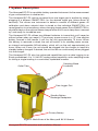
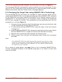
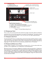
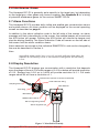
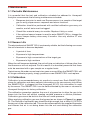
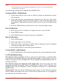
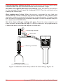
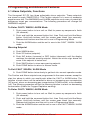
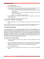
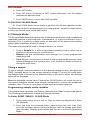
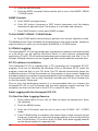
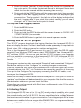
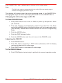
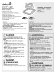
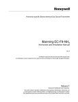
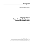
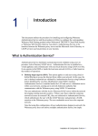
Honeywell EC-P2
EGaC-P2
s Dete
ctor
CHAR
GE BA
TTER
Y WHE
N NO
T IN US
E
Instruction Manual
Copyright 2009 by Honeywell International Inc.
Release J July 2008
While this information is presented in good faith and believed to be accurate,
Honeywell disclaims the implied warranties of merchantability and fitness for a
particular purpose and makes no express warranties except as may be stated in
its written agreement with and for its customers.
In no event is Honeywell liable to anyone for any indirect, special or consequential
damages. The information and specifications in this document are subject to change
without notice.
Manning is a registered trademark of Honeywell International Inc.
Other brand or product names are trademarks of their respective owners.
Honeywell Analytics Inc.
405 Barclay Boulevard
Lincolnshire, Illinois 60069
Tel: 1 847 955 8200
Toll Free: 1 800 538 0360
Fax: 1 847 955 8208
www.honeywellanalytics.com
[email protected]
www.manningsystems.com
Honeywell EC-P2 Instruction and Installation Manual
3
Introduction
This manual has been prepared to help in the use of the Honeywell EC-P2 Portable
Gas Detector.
This manual must be carefully followed by all individuals who have or will
have the responsibility for using or servicing this device.
Warranties made by Honeywell Analytics Inc. with respect to this equipment will be
voided if the equipment is not used and service in accordance with the instructions
in this manual. If in doubt about a procedure, please contact Honeywell Analytics
Inc. before proceeding.
4
Honeywell EC-P2 Instruction and Installation Manual
Table of Contents
Introduction������������������������������������������������������������������������������������4
1 System Description����������������������������������������������������������������������������7
System Specifications��������������������������������������������������������������������������8
2.1 Operating the Sensor���������������������������������������������������������������8
2.2 Changing the Target Gas using SMART-CELL Technology��9
2.3 Response Test������������������������������������������������������������������������10
2.4 Sample Inlet Port��������������������������������������������������������������������10
2.5 Response/Recovery Time������������������������������������������������������10
2.6 Interference Gases�����������������������������������������������������������������11
2.7 Alarm Functions���������������������������������������������������������������������11
2.8 Display Resolution�����������������������������������������������������������������11
3 Maintenance �������������������������������������������������������������������������������������12
3.1 Periodic Maintenance �����������������������������������������������������������12
3.2 Sensor Life �����������������������������������������������������������������������������12
3.3 Calibration �����������������������������������������������������������������������������12
To Enter ZERO / SPAN Mode�������������������������������������������������13
Zero Calibration����������������������������������������������������������������������13
Span Calibration���������������������������������������������������������������������13
To Exit ZERO / SPAN Mode����������������������������������������������������13
3.4 Troubleshooting���������������������������������������������������������������������13
4 Programming and Advanced Features�������������������������������������������15
4.1 Alarm Setpoints, Functions��������������������������������������������������15
To Enter CAUT / WARN / ALRM Mode�����������������������������������15
Warning Setpoint��������������������������������������������������������������������15
To Exit CAUT / WARN / ALRM Mode��������������������������������������15
To Enter CAUT / WARN / ALRM Mode�����������������������������������15
Warning Function��������������������������������������������������������������������16
To Exit CAUT / WARN / ALRM Mode��������������������������������������16
4.2 Display Variables��������������������������������������������������������������������16
To Enter AVG / BLANK Mode��������������������������������������������������16
AVG Variable���������������������������������������������������������������������������17
To Exit AVG / BLANK Mode����������������������������������������������������17
4.3 Sample Mode��������������������������������������������������������������������������17
Taking a sample����������������������������������������������������������������������17
Programming sample mode variables�������������������������������������17
To Enter SAMP / MEAS / CLEAR Mode���������������������������������17
SAMP Variable������������������������������������������������������������������������18
To Exit SAMP / MEAS / CLEAR Mode������������������������������������18
4.4 Data Logging��������������������������������������������������������������������������18
EC-P2 software installation:����������������������������������������������������18
Honeywell EC-P2 Instruction and Installation Manual
5
Data Logging with the Honeywell EC-P2:�������������������������������18
Working with the “EC-P2” program:�����������������������������������������19
4.5 Analog Output������������������������������������������������������������������������19
Changing the full scale range on EC-P2:��������������������������������20
To Enter RANGE Mode�����������������������������������������������������������20
Adjusting the RANGE�������������������������������������������������������������20
To Exit RANGE Mode�������������������������������������������������������������20
Appendix A������������������������������������������������������������������������������������������21
Available SMART-CELLs��������������������������������������������������������������21
Appendix B������������������������������������������������������������������������������������������22
SMART-CELL Cross-Sensitivity Table (Interference Gases) �22
Limited Warranty���������������������������������������������������������������������������������24
6
Honeywell EC-P2 Instruction and Installation Manual
1 System Description
The Honeywell EC-P2 is a portable, battery operated instrument for the measurement
of gas concentrations in ambient air.
The Honeywell EC-P2 can be converted from one target gas to another by simply
plugging in a different SMART-CELL for the desired target gas (takes about 30
seconds). This allows one instrument to detect a number of different gases. All
calibration and alarm setpoint data is stored on the individual SMART-CELL so
reconfiguration is not necessary when changing target gases. Extra SMART-CELLs
should be kept on the optional sensor keeper when not in use to keep them “warmed
up” and ready for immediate use.
The Honeywell EC-P2 utilizes two different batteries to insure that you’ll never be
without power when you need it. The primary power source is a “D” size alkaline
battery housed in the handle. It will run the unit approximately 75 hours. When
this battery is removed or dead, the unit will switch to its standby power source,
an internal rechargeable NiCad battery, which will run the unit approximately six
hours. When not in use, the unit should be plugged into the charger to keep this
standby battery charged. If desired, the unit can be run continuously when plugged
into the charger.
The Honeywell EC-P2 also has advanced capabilities such as data logging to an
Excel spreadsheet, 0 to 1.0 Volt DC analog output capability, and a sampling mode
for taking a single reading in a controlled, repeatable manner.
Sampling Wand
Assembly
Outlet Tube
Data Logger Port
Standby Battery
Recharge Receptacle
Primary Battery
Figure 1. Basic Parts of the Honeywell EC-P2 Sensor
Honeywell EC-P2 Instruction and Installation Manual
7
System Specifications
Alkaline D cell battery, 75 hours operation.
Note: An audible alarm single beep every 60 seconds
indicates that either the Alkaline D cell battery is low or
the internal rechargeable NiCad battery is low.
Primary Power:
Internal rechargeable NiCad battery, 6 hours
operation.
Standby Power:
Note: An audible alarm single beep every 60 seconds
indicates that either the Alkaline C cell battery is low or
the internal rechargeable NiCad battery is low.
Charger:
120 VAC plug-in charger for internal standby battery
Display:
Backlit LCD
Pump:
Miniature internal diaphragm type, flowrate 0.5
SCFH
Alarms:
Two concentration alarms, zero drift caution, Low flow
and Low battery alarms. Alarms displayed on LCD and
indicated by audible beeper.
Standard Accessories:
Storage case, 10” extension wand, battery charger,
filter material, datalogging software, RS-232 output
cable (DB9 connector)
Optional Accessories:
Analog output cable. Sensor Keeper for storage of
additional SMART-CELLs
Sensor Type:
Target gas selective electrochemical SMART-CELL
Accuracy:
Sensor dependant but generally ± 5% of reading
Repeatability:
± 1% full scale
Operating Ambient Temperature
Range:
0° to +120° F
Storage Temperature:
Recommend storing on the charger in an air
conditioned office
Weight:
3 lbs. (shipping weight), 1.8 lbs. (detector only)
Dimensions:
Approx 3.5” x 5” x 8.5”
RS-232 output of stored gas values.
Outputs:
Analog output 0 to 1.0 VDC (requires optional
analog output cable)
12,000 data points, storage interval between points
programmable at 1, 5, 10, or 15 minutes. Typical
capacity: 8 days at 1 minute storage interval
Memory:
2.1 Operating the Sensor
The Honeywell EC-P2 is shipped ready for use. To power up the instrument, push
the PWR button. The power up sequence displays first the self check, the sensor
full scale value, the downscale caution level, warning concentration setpoint, alarm
concentration setpoint, output ranges, software version, then the normal operating
screen.
The unit will then display the instantaneous gas concentration and is ready for
use.
8
Honeywell EC-P2 Instruction and Installation Manual
The normal operating screen displays the information as shown in Figure 2.
The Honeywell EC-P2 is designed to avoid accidental shut-off of the power. To turn
the unit off, the PWR button must be held down for approximately three seconds.
Release the button after the “Power Down” message appears.
2.2 Changing the Target Gas using SMART-CELL Technology
The Honeywell EC-P2 can easily be changed to sense another target gas by
installing the SMART-CELL for the desired target gas. Each SMART-CELL contains
all the calibration and alarm setpoint information on its internal memory chip, so
recalibration or reprogramming is not necessary when changing the Honeywell
EC-P2 from one gas to another. This procedure can be performed with the unit
powered on or off (see Figure 3).
1. Unscrew the two stainless steel thumbscrews and remove the black inlet
/ outlet manifold lid from the back of the unit.
2. To remove the existing SMART-CELL, grip the sides of the cell and pull
it straight out.
3. Install the desired SMART-CELL by gently inserting it into the socket. Notice
that the SMART-CELL is keyed so it cannot be inserted incorrectly.
4. Replace the manifold and hand tighten the thumbscrews.
5. Verify proper flow through the sampling wand using the flowmeter
provided.
Note:
Extra SMART-CELLS should be kept on the optional sensor keeper when
not in use to keep them “warmed up” and ready for immediate use. The
sensor keeper is powered by an Alkaline “D” size battery which should
be replaced every 6 months.
For a variety of target gases, see page 19 for a list of available SMART-CELLs.
Contact Honeywell Analytics if the desired target gas is not listed, as new cells
may be available.
Honeywell EC-P2 Instruction and Installation Manual
9
BATTERY IN USE
P = Primary (“D” cell)
S = Standby (Internal NiCad)
Flashing indicates low battery
0
P
A
OFF
CURRENT GAS CONCENTRATION
(Blinking indicates sensor over range)
TARGET GAS
SMART-CELL dependent
PPM
NH3
MENU SMPL
Battery Light
Power
ADVANCED FEATURES ONLY
Do not push for normal operation
ALARM INDICATION CODE
Blank = No alarm condition present
C = Caution—Cell has excessive zero downdrift
W = Warning—Gas concentration has exceeded warning level
A = Alarm—Gas concentration has exceeded alarm level
P = Pump trouble
Lg = Data logging in progress
Figure 2. Normal Operating Screen
2.3 Response Test
Prior to use, the unit should first be tested for proper response. With the detector
operating, the unit should be exposed to a sample of the target gas. The display should
show an increasing concentration. If not, do not use it for field measurements.
2.4 Sample Inlet Port
The Honeywell EC-P2 is provided with a quick disconnect flexible extension wand.
It will work with or without the wand. When using the extension wand, the internal
walls must be kept dry. Water on the walls of the tubing can potentially absorb the
target gas. To dry, allow the unit to pump dry, ambient air for 15 minutes.
2.5 Response/Recovery Time
Under normal conditions, the instrument will reach 90% of final value within two
minutes. This is dependent on concentration and temperature.
Recovery time for the sensor depends on duration and concentration of exposure.
Short exposures of concentrations at the lower end of the target gas range result in
rapid recovery. Long exposures to levels above the middle of the target gas range
or short exposures to levels exceeding the target gas range can extend recovery
times to hours. Repeated exposures above the target gas range will reduce cell life
and should be avoided.
10
Honeywell EC-P2 Instruction and Installation Manual
2.6 Interference Gases
The Honeywell EC-P2 is generally quite specific to the target gas, but depending
on the target gas, other gases may cause a reading. See Appendix B for a listing
of potential interference gases for the various SMART-CELLs.
2.7 Alarm Functions
The Honeywell EC-P2 provides both visible and audible gas concentration alarms
and system alarms. An alarm condition will be displayed on the normal operating
screen as described on page 8.
In addition to the alarm indication code in the left side of the screen, an alarm
message will flash intermittently on the screen, the audible beeper will sound and
the ACK button will appear. Pushing the ACK button will silence the beeper and
stop the display flashing. The Alarm Indication Code will remain on the left side of
the screen until the alarm condition clears.
Alarm setpoints are stored on the individual SMARTCELL and can be changed by
the user as described in Section 4.
Note:
An audible alarm single beep every 60 seconds indicates that either the
Alkaline D cell battery is low or the internal rechargeable NiCad battery
is low.
2.8 Display Resolution
The Honeywell EC-P2 displays gas concentration with a resolution that depends
upon the range of the unit. Full scale ranges of 0-4.00 or below will provide resolution
of 0.01. Ranges from 0-5.0 up to 0-49.9 will provide resolution of 0.1. Full scale
ranges above 50 will have a resolution of 1.
Thumbscrews (loosen to remove manifold lid)
Outlet tube barb fitting
Sampling Wand
TEST UNIT PRIOR TO USE
OUTLET
Filter Material
INLET
Inlet fitting
CAUTION
DO NOT BLOCK INLET
OR OUTLIET PORTS
Manifold lid
SMART-CELL Sensor
Sensor alignment groove
Sensor alignment pin
Figure 3. Manifold Assembly
Honeywell EC-P2 Instruction and Installation Manual
11
3 Maintenance
3.1 Periodic Maintenance
It is essential that the test and calibration schedule be adhered to. Honeywell
Analytics recommends the following maintenance schedule:
• Response test prior to each use. Expose sensor to a sample of the target
gas to verify proper sensor response and alarm functions.
• Calibration should be performed with certified calibration gas every six
months, and all tests must be logged.
• Check filter material every six months. Replace if dirty or moist.
• If the optional sensor keeper is used for extra SMART-CELLs, change the
sensor keeper battery once every 6 months. Use only alkaline “D” size
batteries.
3.2 Sensor Life
The electrochemical SMART CELL is extremely reliable, but the following can cause
the cell chemicals to become depleted:
• A period of time
• Exposure to high temperatures
• Exposure to high concentrations of the target gas
• Exposure to high moisture
When the cell becomes depleted, the unit will give no indication of failure other than
that the sensor will not respond. For this reason it is absolutely essential that these
units be exercised with a gas sample on a regular basis.
Typical sensor life under normal use is two years or more. When the SMART-CELL will
no longer calibrate properly, simply purchase a new SMART-CELL and replace.
3.3 Calibration
Calibration is recommended every six months in normal use. Each SMART-CELL
stores its calibration and alarm setpoint information on its own memory chip. When
the SMART-CELL is plugged into the Honeywell EC-P2, this information is used
by the sensor. The SMART-CELL can be field calibrated by the user or returned to
Honeywell Analytics for factory calibration.
The calibration procedure requires the use of a bypass tee to allow the gas to be
drawn into the flow cell without creating variable pressure or dilution problems.
Calibration gas cannot be fed into the flow cell under pressure.
When applying calibration gas use the bypass tee as shown in Figure 4 on page
11. The flowrate of calibration gas should be high enough that at least 0.5 SCFH is
flowing out of the calibration tee. This can be measured with the supplied flowmeter
and insures that air is not being drawn into the unit and diluting the calibration
gas.
12
Honeywell EC-P2 Instruction and Installation Manual
Note:
The unit may be zeroed without spanning it; however, never span the unit
without first zeroing it.
The following procedure will calibrate the SMART-CELL.
To Enter ZERO / SPAN Mode
1. Push power button to turn unit on. Wait for power up sequence to finish
(30 seconds).
2. Push and hold the unnamed button (second from left) first, then Push
and hold the Menu button. Hold both buttons until the screen goes blank
(2 seconds). Release both buttons and the unit is now in Programming
Mode.
3. Push the SENS button and the unit is now in the zero/span mode. Zero Calibration
4. Be sure the unit is in clean air or apply zero air for two minutes.
5. Push ZERO button.
6. Push SAVE button to save the new zero calibration.
Span Calibration
7. Push SPAN button.
8. Apply span gas for two minutes.
9. Push INC button (increase) or DEC button (decrease) until the display
matches the span gas concentration.
10.Push SAVE button to store new span calibration.
To Exit ZERO / SPAN Mode
11.Push DONE button twice slowly to get back into normal operation mode.
3.4 Troubleshooting
The detector does not start: Check to see that a fresh battery is installed. Both
the primary and standby batteries must be discharged for this problem to occur.
Plug the charger into the Honeywell EC-P2 to charge the standby battery. Wait 10
minutes and retry.
The detector does not respond to the target gas: Verify the proper flow rate
using the supplied flowmeter. Perform calibration. If sensor won’t calibrate, the
SMART-CELL may be depleted. Contact Honeywell Analytics for a replacement
SMART-CELL.
Pump alarm: This will occur if the pump motor stops or if an internal pressure
sensor detects blockage of the inlet. Check that the internal filter is not clogged or
wet and that the inlet tube is clear.
Honeywell EC-P2 Instruction and Installation Manual
13
External flowmeter indicates no flow: Verify that pump is running. Check that the
manifold screws are tight and the extension wand connection is tight.
Unit does not respond when keys are pressed: Press and hold all four buttons
for five seconds. This will reset the Honeywell EC-P2. Turn the unit back on by
pressing the PWR button.
High reading won’t clear: When the sensor is exposed to very high gas
concentrations, it takes a relatively long time for the sensor to clear. Leave the unit
running in a clean environment for a few hours to clear the sensor. If it doesn’t clear
after six hours, the sensor may have been damaged. Contact Honeywell Analytics
for a replacement SMART-CELL.
Unit is in alarm with gas reading of 0 ppm: Check the alarm setpoints and
alarm functions as described on page 12. Verify that alarm is not programmed as
a downscale alarm, and that the setpoint is above zero.
Vent through flowmeter
Bypass Tee
TEST UNIT PRIOR TO USE
OUTLET
INLET
1.0
.8
.6
CAUTION
Calibration gas flowmeter
DO NOT BLOCK INLET
OR OUTLIET PORTS
.4
.2
LPM AIR
Calibration gas bottle
(use only Certified Calibration Gas)
Figure 4. Calibration of the Honeywell EC-P2 Sensor using a Bypass Tee
14
Honeywell EC-P2 Instruction and Installation Manual
4 Programming and Advanced Features
4.1 Alarm Setpoints, Functions
The Honeywell EC-P2 has three adjustable alarm setpoints. These setpoints
are stored on each SMART-CELL. The Caution setpoint is to warn of excessive
negative zero drift. The WARNING and ALARM setpoints are to warn of potentially
dangerous target gas concentrations. The following procedure will change the
WARNING setpoint.
To Enter CAUT / WARN / ALRM Mode
1. Push power button to turn unit on. Wait for power up sequence to finish
(30 seconds).
2. Push and hold the unnamed button first, then Push and hold the Menu
button. Hold both buttons until the screen goes blank (two seconds).
Release both buttons and the unit is now in Programming Mode.
3. Push the ALRM button and the unit is now in the CAUT / WARN / ALRM
mode.
Warning Setpoint
4. Push WARN button.
5. Push S.P. button (setpoint).
6. Push INC button (increase) or DEC button (decrease) until the display
matches the desired warning setpoint. Notice the minus sign above the
arrow if the setpoint is below zero.
7. Push SAVE button to store new warning setpoint.
8. Push DONE button to return to Alarms mode.
To Exit CAUT / WARN / ALRM Mode
9. Push DONE button twice slowly to get back into normal operation mode.
The Caution and Alarm setpoints are programmed in the same manner, except for
step four above in which you would push either the CAUT or ALRM button. The
function of each alarm can be selected to alarm on increasing gas concentration
(UP arrow), alarm on decreasing gas concentration (DOWN arrow), or be disabled
(off). The following procedure will set the Warning function to alarm on decreasing
concentration (Useful for Oxygen Depletion warning).
To Enter CAUT / WARN / ALRM Mode
1. Push power button to turn unit on. Wait for power up sequence to finish
(30 seconds).
2. Push and hold the unnamed button first, then Push and hold the Menu
button. Hold both buttons until the screen goes blank (two seconds).
Release both buttons and the unit is now in Programming Mode.
3. Push the ALRMS button and the unit is now in the CAUT / WARN / ALRM
mode.
Honeywell EC-P2 Instruction and Installation Manual
15
Warning Function
4. Push WARN button.
5. Push FUNC (function) button.
6. Push SELECT button while viewing the arrow in the lower left hand corner
of the screen to toggle through the following three possibilities:
• UP arrow — Warn on increasing concentration (gas goes higher
than setpoint).
• DOWN arrow — Warn on decreasing concentration (gas goes
lower than setpoint).
• Blank — warning function turned OFF.
7. Push SAVE button when the DOWN arrow is displayed to store new
warning function.
8. Push DONE button to return to Alarms mode.
To Exit CAUT / WARN / ALRM Mode
9. Push DONE button two times slowly to get back into normal operation
mode.
The Caution and Alarm functions are programmed in the same manner, except for
step four above in which you would push either the CAUT or ALRM button.
4.2 Display Variables
The Honeywell EC-P2 has two adjustable display variables. These variables control
signal conditioning of the LCD display. Variables are stored on each SMART-CELL.
The AVG (Average) variable determines the number of one second samples to
average to calculate the displayed value. The lower the averaging value, the faster
the display will change and the more “wiggle” will be displayed. The BLANK (zero
blanking) variable controls the lowest reading that will be displayed. This is to
eliminate the misleading display of signals within the zero noise of the sensor. The
following procedure will change the AVG variable.
To Enter AVG / BLANK Mode
1. Push power button to turn unit on. Wait for power up sequence to finish
(30 seconds).
2. Push and hold the unnamed button first, then Push and hold the Menu
button. Hold both buttons until the screen goes blank (two seconds).
Release both buttons and the unit is now in Programming Mode.
3. Push the MORE button.
4. Push the DISP (display) button and the unit is now in the AVG / BLANK
mode.
16
Honeywell EC-P2 Instruction and Installation Manual
AVG Variable
5. Push AVG button.
6. Push INC button (increase) or DEC button (decrease) until the display
matches the desired value.
7. Push SAVE button to store new AVG variable.
To Exit AVG / BLANK Mode
8. Push DONE button twice slowly to get back into normal operation mode.
The Blanking variable is programmed in the same manner, except for step 5 above
in which you would push the BLANK button.
4.3 Sample Mode
The Sample Mode feature allows the user to take a measurement using a predefined
repeatable method to eliminate user “interpretation” of a gas concentration that is
changing. This is similar to a digital scale, for example, so the exact same reading
will be taken regardless of who is taking it.
The measuring sequence used in Sample Mode is as follows:
• Draw a Sample for a user programmed sampling time to allow unit to
stabilize to the existing gas concentration.
• Measure the gas concentration and average it for a user programmed
measuring time.
• Clear the gas concentration to below a user programmed recovery value
before allowing another cycle to start. (Unit should be moved to fresh air
during the clear time.)
Taking a sample
To take a sample, locate the detector at the desired sample location, and push the
SMPL (sample) button on the normal operation screen. The unit will count down
the Sample time, followed by the Measure time, at the end of which the average
value will be displayed.
Note the displayed sample value. Pushing the CLEAR button will return the unit to
the normal operation screen once the gas concentration is below the predefined
recovery value. The unit is now ready to take another sample if desired.
Programming sample mode variables
The sample mode variables are Sample, Measure and Clear as described above.
The following procedure will change the Sample variable.
To Enter SAMP / MEAS / CLEAR Mode
1. Push power button to turn unit on. Wait for power up sequence to finish
(30 seconds).
2. Push and hold the unnamed button (second from left) first, then Push
and hold the Menu button. Hold both buttons until the screen goes blank
(two seconds). Release both buttons and the unit is now in Programming
Mode.
Honeywell EC-P2 Instruction and Installation Manual
17
3. Push the MORE button.
4. Push the SMPL (sample) button and the unit is now in the SAMP / MEAS
/ CLEAR mode.
SAMP Variable
5. Push SAMP (sample) button.
6. Push INC button (increase) or DEC button (decrease) until the display
matches the desired value. The display is in minutes and seconds.
7. Push SAVE button to store new SAMP variable.
To Exit SAMP / MEAS / CLEAR Mode
8. Push DONE button twice slowly to get back into normal operation mode.
The Measure and Clear variables are programmed in the same manner, except for
step five above in which you would push the MEAS or CLEAR button.
4.4 Data Logging
The Honeywell EC-P2 can log periodic gas concentration readings to be downloaded
to a file which can be read by Microsoft Excel or other popular spreadsheet
applications. The EC-P2 will store instantaneous gas values every one, five, 10, or 15
minutes. Multiple sessions can be logged and then downloaded as separate files.
EC-P2 software installation:
The Honeywell EC-P2 is supplied with a CD containing the “Honeywell EC-P2”
program. It will run on Windows 98, Windows 2000 or Windows XP. To install the
program, place the disk in your CD drive. The CD should automatically begin the
installation process. Follow the prompts as they appear on your screen. Accepting
the default directory locations is recommended for most installations. If the CD does
not automatically start, click on “My Computer” and then your CD drive. Double-click
on the file named “Setup.exe.”
Prior to your first datalogging session it is recommended that you connect the
Honeywell EC-P2 to your computer with the data logging program running. The
computer can then set the time in the EC-P2 to match its own clock.
Data Logging with the Honeywell EC-P2:
To Start the Data Logging Session
1. Push power button to turn unit on. Wait for power up sequence to finish
(30 seconds).
2. Push the MENU button.
3. Push the LOG button and the unit is now in the CLEAR / INT / START
mode.
4. If the CLEAR button is available, that means there is data currently stored
in the unit. If desired, you can erase the data already in the unit by pushing
the CLEAR button. (If you don’t push CLEAR, each data logging session
can be downloaded as a separate file).
18
Honeywell EC-P2 Instruction and Installation Manual
5. Push INT button (interval) to cycle through the choices for how often to
log a data point. Stop when the desired interval is displayed. Notice how
much time can be covered with the remaining free memory.
6. Push and hold the START button until the screen goes blank (two seconds)
to begin a new data logging session. The unit will now display the gas
concentration. The Lg symbol in the left side of the display indicates that
the unit is logging data. If you watch this symbol carefully, you will see it
change to an “s” each time a data point is stored.
To Stop the Data Logging Session
7. Push the MENU button.
8. Push the LOG button.
9. Push and hold the STOP button until the screen changes to CLEAR / INT
/ START / MODE (two seconds).
10.Push the DONE button to get back into normal operation mode.
Working with the “EC-P2” program:
The “EC-P2” program downloads the logging files from the Honeywell EC-P2. It
does not display the data. The files it downloads can be opened by or imported into
Excel, Lotus 123 or other programs for graphing and analysis.
Turn on the Honeywell EC-P2 and connect it to your PC using the RS-232 cable
supplied. From Windows START menu, select “PROGRAMS,” then “Honeywell ECP2,” and then “EC-P2”. As soon as you start the “EC-P2” program, your computer
will try to establish a connection to the Honeywell EC-P2. If the Honeywell EC-P2
is currently logging data, the “EC-P2” program will automatically stop the logging
function.
The program contains two tabs, one marked “Download” and one marked “Configure”.
Review the settings on the “Configure” tab, making changes as necessary.
From the “Download” tab, review the Link Status block in the lower right hand corner.
It should indicate “Link OK”. Link Trouble can be caused by selection of the wrong
Com port in the Configure Tab, improperly connecting the RS-232 cable, or not
turning on the Honeywell EC-P2.
When you are ready to transfer data from the Honeywell EC-P2 to your PC, click on
“get data” and the files will be downloaded to your computer. Note the file names in
the destination window so you can locate the files.
These files can now be opened with Excel (use .csv filename), Lotus 123, or other
user supplied programs.
4.5 Analog Output
The Honeywell EC-P2 has a 0 to 1.0 volt DC analog output capability when used
with the optional analog output cable. With the analog output cable plugged into
the communication port of the EC-P2, the user can measure the voltage between
the two wires and correlate it to gas concentration. The voltage output will be linear
between zero and the full scale range of the SMART-CELL as programmed below.
Honeywell EC-P2 Instruction and Installation Manual
19
Each SMARTCELL has a wide range of choices of full scale values.
Note:
The full scale range as programmed below only affects the analog output
and the data logging full-scale output.
The display will always cover the entire operating range of the SMART-CELL.
Changing the range can affect the display resolution for some SMART-CELLs.
Changing the full scale range on EC-P2:
To Enter RANGE Mode
1. Push power button to turn unit on. Wait for power up sequence to finish
(30 seconds).
2. Push and hold the unnamed button (second from left) first, then Push
and hold the MENU button. Hold both buttons until the screen goes blank
(two seconds). Release both buttons and the unit is now in Programming
Mode.
3. Push the MORE button.
4. Push the DISP (display) button.
5. Push the MORE button and the unit is now in the RANGE mode.
Adjusting the RANGE
6. Push RANGE button.
7. Push INC button (increase) or DEC button (decrease) until the display
matches the desired full scale range.
8. Push SAVE button to store new full scale range.
To Exit RANGE Mode
9. Push DONE button twice slowly to get back into normal operation mode.
20
Honeywell EC-P2 Instruction and Installation Manual
Appendix A
Available SMART-CELLs
Gas
Min Range
Max Range
Resolution
Part Number
Alcohol
0-50 ppm
0-500 ppm
1 ppm
10167
Ammonia (NH3)
0-50 ppm
0-500 ppm
1 ppm
10168
Ammonia (NH3)
0-500 ppm
0-2000 ppm
1 ppm
10169
Bromine (Br2)
0-1 ppm
0-5 ppm
0.01 ppm
10170
Chlorine (Cl2)
0-5 ppm
0-100 ppm
0.1 ppm
10216
Chlorine (Cl2)
0-1 ppm
0-5 ppm
0.01 ppm
10172
Chlorine Dioxide (ClO2)
0-5 ppm
0-5 ppm
0.1 ppm
10173
Carbon Monoxide (CO)
0-50 ppm
0-1000 ppm
1 ppm
10171
Ethylene Oxide (ETO)
0-20 ppm
0-200 ppm
0.1 ppm
10944
0-1 ppm
0-5 ppm
0.01 ppm
10174
Fluorine (F2)
Hydride gases
0-500 ppb
0-2000 ppb
1 ppb
10945
Hydrogen (H2)
0-500 ppm
0-2000 ppm
1 ppm
10176
Hydrogen Peroxide (H2O2)
0-10 ppm
0-100 ppm
1 ppm
10178
Hydrogen Sulfide (H2S)
0-10 ppm
0-200 ppm
0.1 ppm
10179
Formaldehyde (CH2O)
0-20 ppm
0-200 ppm
0.1 ppm
10175
Hydrogen Chloride (HCl)
0-10 ppm
0-200 ppm
0.1 ppm
10177
Hydrogen Cyanide (HCN)
0-10 ppm
0-200 ppm
0.1 ppm
11044
Nitric Oxide (NO)
0-50 ppm
0-500 ppm
1 ppm
10180
Nitrogen Dioxide (NO2)
0-10 ppm
0-200 ppm
0.1 ppm
10181
Oxygen (O2)
0-5%
0-25%
0.1%
10182
Ozone (O3)
0-5 ppm
0-100 ppm
0.1 ppm
10183
Ozone (O3)
0-1 ppm
0-5 ppm
0.01 ppm
11023
0-200 ppm
0-2000 ppm
1 ppm
11187
0-10 ppm
0-500 ppm
0.1 ppm
10184
Phosphine (PH3)
Sulfur Dioxide (SO2)
Honeywell EC-P2 Instruction and Installation Manual
21
22
Cl2
None
None
None
None
-0.04
None
None
Carbon dioxide
Methane
Carbosulfonic acid
Ethylene
Ethyl alcohol
None
None
-0.04
None
None
-0.04
None
None
None
None
None
Silica hydride
None
None
None
-0.08
None
None
1.0
None
None
-0.01
0.2
-0.1
None
None
None
None
None
1.5
-----
1.0
1.0
ClO2
None
None
None
Hydroflouric acid
-0.08
None
-0.01
0.2
-0.1
None
Hydride
-0.08
1.0
Alcohol
Flourine
Hydrogen cyanide
None
None
Formaldehyde
None
-0.01
None
Sulfur dioxide
None
1.0
0.2
Nitrogen dioxide
Hydrochloric acid
None
-0.1
Hydrogen peroxide
None
None
Nitrogen oxide
Hydrogen sulfide
None
None
None
None
Hydrogen
None
None
1.5
1.0
-----
1.0
Oxygen
None
None
1.0
1.5
Chlorine dioxide
Ozone
Carbon monoxide
1.0
Chlorine
Ammonia
-----
BR2
Bromine
O3
None
None
-0.03
None
None
None
None
None
-0.05
None
None
0.7
None
None
-0.01
0.15
-0.07
None
None
None
None
None
-----
0.7
0.7
0.7
0.01
None
None
None
None
0.5
0.5
None
None
0.03
None
-0.1
0.03
0.03
None
None
0.3
None
None
0.02
0.05
-----
-0.1
-0.1
-0.1
-0.1
NH3
CO
None
0.1
None
None
None
None
None
None
0.1
0.1
None
None
0.1
0.1
None
None
None
0.1
None
0.1
-----
None
None
None
None
None
H2
None
0.1
None
None
None
None
None
None
None
0.1
None
None
0.1
0.1
None
None
None
None
None
-----
0.1
None
None
None
None
None
O2
None
None
None
None
None
None
None
None
None
None
None
None
None
None
None
None
None
None
-----
None
None
None
None
None
None
None
NO
0.001
None
None
None
None
1
1
None
None
0.05
None
None
0.05
0.05
None
None
None
-----
None
0.001
None
None
None
None
None
None
H2S
0.005
None
0.3
None
None
0.5
0.5
None
None
0.01
None
None
0.01
0.01
0.1
0.1
-----
0.4
None
0.001
0.002
None
None
None
None
None
0.001
None
-0.8
None
None
-2
-2
None
-0.07
None
-0.3
0.5
None
None
-1
-----
-2.5
0.001
None
0.001
0.001
None
0.65
0.5
0.5
0.5
NO2
0.05
None
None
None
None
2
2
None
0.15
0.02
None
-0.1
0.02
0.02
-----
-0.08
None
0.04
None
0.005
None
None
-0.1
-0.1
-0.1
-0.1
SO2
2
1
1
None
None
2
2
None
0.1
None
0.2
None
None
-----
0.4
0.1
2
0.8
None
0.05
0.5
None
None
None
None
None
HCHO
OH
2
1
1
None
None
2
2
None
0.1
None
0.2
None
-----
1.2
0.4
0.1
2
0.8
None
0.05
0.5
None
None
None
None
None
None
None
-0.04
None
None
None
None
None
-0.08
None
None
-----
None
None
-0.01
0.2
-0.1
None
None
None
None
None
1.5
1.0
1.0
1.0
Fl2
HCl
0.01
None
1
None
None
1.5
1.5
None
0.01
None
-----
None
None
None
0.5
0.2
3
1.5
None
0.01
0.005
None
None
None
None
None
0.02
None
1.3
None
None
2
2
None
0.1
-----
0.1
None
0.1
0.1
1
0.2
4
1.5
None
0.01
0.005
None
None
None
None
None
H2O2
Appendix B
SMART-CELL Cross-Sensitivity Table (Interference Gases)
Honeywell EC-P2 Instruction and Installation Manual
Notes: 1. None means there is no interference. 2. A number indicates that when exposed to the interference gas, the sensor
will react the specified amount for a given concentration. For example,
on the first line of the table above, if the NO2 sensor is exposed to 1 ppm
Bromine (Br2), the sensor will read 0.5 ppm. This interference is in addition
to the target gas present. For example, if an NH3 sensor is exposed to 1 ppm NH3 and 1 ppm Br2 at
the same time, the reading will be 0.9 ppm Honeywell EC-P2 Instruction and Installation Manual
23
Limited Warranty
1. Limited Warranty
Honeywell Analytics Inc.. (“HA”) warrants
to the original purchaser and/or ultimate
customer (“Purchaser”) of HA’s Products
(“Product”) that if any part thereof
proves to be defective in material os
workmanship within eighteen (18)
months of the date of shipment by HA
or twelve (12) months from the date of
first use by the Purchaser, whichever
comes first, such defective part will be
repaired or replaced, free of charge,
at HA’s discretion. For service repairs,
contact HA at
1 800 321 6320
to obtain a service authorization number,
then ship prepaid to
Honeywell Analytics Inc.
405 Barclay Blvd
Lincolnshire, IL 60069
Attn: Service Dept
The Product must be in a package
equal to or in the original container.
The Product will be returned freight
prepaid and repaired or replaced if it is
determined by HA that the part failed due
to defective materials or workmanship.
The repair or replacement of any such
defective part shall be HA’s sole and
exclusive responsibility and liability
under this limited warranty.
2. Exclusions
A. If gas sensors are par t of the
Product, the gas sensor is covered
by a twelve (12) month limited
warranty of the manufacturer.
B. If gas sensors are covered by this
limited warranty, the gas sensor
is subject to inspection by HA for
extended exposure to excessive
gas concentrations if a claim by
the Purchaser is made under this
limited warranty.
C. This limited warranty does not cover
consumable items such as batteries,
or items subject to wear or periodic
adjustment, including lamps, fuses,
valves, vanes, sensor elements,
cartridges, or filter elements.
24
3. Warranty Limitation and
Exclusion
Honeywell Analytics will have no further
obligation under this limited warranty.
All warranty obligations of Honeywell
Analytics are extinguishable if the
Product has been subject to abuse,
misuse, negligence, or accident or if
the Purchaser fails to perform any of the
duties set forth in this limited warranty
or if the Product has not been operated
in accordance with the instructions, or
if the Product serial number has been
removed or altered.
4. Disclaimer of Unstated
Warranties
THE WARRANTY PRINTED ABOVE IS
THE ONLY WARRANTY APPLICABLE
TO THIS PURCHASE. ALL OTHER
WARRANTIES, EXPRESS OR IMPLIED,
INCLUDING, BUT NOT LIMITED TO
THE IMPLIED WARRANTIES OF
MERCHANTABILITY OR FITNESS
FOR A PARTICULAR PURPOSE ARE
HEREBY DISCLAIMED.
5. Limitation of Liability
IT IS UNDERSTOOD AND AGREED
THAT HONEYWELL ANALYTICS’
LIABILITY, WHETHER IN CONTRACT,
IN TORT, UNDER ANY WARRANTY, IN
NEGLIGENCE OR OTHERWISE SHALL
NOT EXCEED THE AMOUNT OF THE
PURCHASE PRICE PAID BY THE
PURCHASER FOR THE PRODUCT
AND UNDER NO CIRCUMSTANCES
SHALL HONEYWELL ANALYTICS BE
LIABLE FOR SPECIAL, INDIRECT,
OR CONSEQUENTIAL DAMAGES.
T H E P R I C E S TAT E D F O R T H E
PRODUCT IS A CONSIDERATION
LIMITING HONEYWELL ANALYTICS’
LIABILITY. NO ACTION, REGARDLESS
OF FORM, ARISING OUT OF THE
T R A N S AC T I O N S U N D E R T H I S
WARRANTY MAY BE BROUGHT BY
THE PURCHASER MORE THAN ONE
YEAR AFTER THE CAUSE OF ACTION
HAS OCCURRED.
Honeywell EC-P2 Instruction and Installation Manual
Honeywell EC-P2 Instruction and Installation Manual
25
Find out more
www.honeywellanalytics.com
Contact Honeywell Analytics:
Americas
Honeywell Analytics
405 Barclay Boulevard
Lincolnshire, IL 60069
USA
Tel: +1 847 955 8200
Toll free: +1 800 538 0363
Fax: +1 847 955 8208
[email protected]
Please Note:
While every effort has been made to ensure accuracy in this publication, no
responsibility can be accepted for errors or omissions.
Data may change, as well as legislation, and you are strongly advised to obtain
copies of the most recently issued regulations, standards and guidelines.
This publication is not intended to form the basis of a contract.
11385 Rev J
July 2009
Technical Services
[email protected]
www.honeywell.com
© 2009 Honeywell Analytics