1
LibraryXpress™ Series
DLT Library System
Including
LXG, LXB, and LXC Modules
and XpressChannel
Service Manual
DIGITAL Part Number
EK–TL890–SV. A01
104140-101, Revision A
7/97
PROPRIETARY NOTICE
All information contained in or disclosed by this document is considered proprietary by Overland Data. By accepting this
material the recipient agrees that this material and the information contained therein are held in confidence and in trust and will
not be used, reproduced in whole or in part, nor its contents revealed to others, except to meet the purpose for which it was
delivered. It is understood that no right is conveyed to reproduce or have reproduced any item herein disclosed without express
permission from Overland Data.
Overland Data provides this manual "as is," without warranty of any kind, either expressed or implied, including, but not
limited to, the implied warranties of merchantability and fitness for a particular purpose. Overland Data may make
improvements or changes in the product(s) or programs described in this manual at any time. These changes will be
incorporated in new editions of this publication.
Overland Data assumes no responsibility for the accuracy, completeness, sufficiency, or usefulness of this manual, nor for any
problem that might arise from the use of the information in this manual.
In May 1993, Overland Data, Inc. acquired the engineering, manufacturing and marketing rights for selected Cipher products.
Cipher is now a brand name of Overland Data, Inc.
Worldwide Headquarters
8975 BALBOA AVENUE
SAN DIEGO, CA 92123-1599
TOLL FREE: (800) 729-8725
TEL: (619) 571-5555
FAX: (619) 571-0982
TEL: (619) 571-5555
FAX: (619) 571-3664
EMAIL: [email protected]
SALES
FTP:
ftp://ovrland.com/pub/odisales
http://www.overlanddata.com
WWW:
TECHNICAL SUPPORT
TEL:
BBS:
(619) 571-5555 FAX: (619) 571-3664
(619) 571-3651
28.8 kbaud, no parity, 8 bits, 1 stop bit
Protocols: ASCII, Xmodem (checksum),
Xmodem (CRC), Xmodem (1K), Ymodem (batch),
Ymodem (G), Zmodem, Zmodem (resume
after abort), Kermit/super Kermit
Overland Data (Europe) Ltd.
ii
UNIT 3, ASHVILLE WAY
WOKINGHAM, BERKSHIRE
RG41 2PL, ENGLAND
TEL: (+44) 1189-891891 FAX: (+44)
INTERNET: [email protected]
1189-891897
CONTENTS
CHAPTER 1 - INTRODUCTION .................................................................................. 1
MODULES .......................................................................................................................... 1
SmartScale Storage™ Architecture............................................................................... 2
The Global Control Module .......................................................................................... 2
The Base Module .......................................................................................................... 3
The Capacity Module.................................................................................................... 3
SCSI INTERFACE CONFIGURATIONS .................................................................................... 3
SCSI BUS PERFORMANCE CONSIDERATIONS........................................................................ 4
Data Transfer Rate .......................................................................................................4
Drives ........................................................................................................................... 4
Internal Cabling Configuration..................................................................................... 4
Bus Length Limitations ................................................................................................. 4
PHYSICAL CONFIGURATION ................................................................................................ 4
SYSTEM EXPANSION ........................................................................................................... 5
Conversion of Free-Standing Base Modules for System Use.......................................... 5
FEATURES .......................................................................................................................... 5
Control Panel ...............................................................................................................6
Power Supply................................................................................................................7
Tape Cartridge Magazines ............................................................................................ 7
Integral Fan Cooling ....................................................................................................9
Library Robotics ...........................................................................................................9
Bar Code Reader ..........................................................................................................9
ADVANCED DESIGN FEATURES ........................................................................................... 9
Embedded Diagnostics................................................................................................ 10
Error Checking ........................................................................................................... 10
Buffer.......................................................................................................................... 10
Compression ............................................................................................................... 10
Capacity ..................................................................................................................... 10
Media Life .................................................................................................................. 11
RELATED PUBLICATIONS .................................................................................................. 11
CHAPTER 2 - INSTALLATION.................................................................................. 13
INTRODUCTION ................................................................................................................ 13
PLANNING YOUR INSTALLATION ....................................................................................... 13
Positioning the Modules.............................................................................................. 14
MECHANICAL INSTALLATION ............................................................................................ 14
Identifying the Parts of the XpressChannel ................................................................. 14
Orientation of Parts During Assembly......................................................................... 16
Preparing to Assemble the XpressChannel .................................................................. 17
Assembling the XpressChannel.................................................................................... 17
Installing the Belt........................................................................................................ 19
Adding to an Existing XpressChannel ......................................................................... 23
Mounting the Module Rack Slides ............................................................................... 23
Installing the XpressChannel in the Rack .................................................................... 26
INTERFACES AND CABLING ............................................................................................... 28
XpressChannel Motor Cable ....................................................................................... 29
Control Cables............................................................................................................ 29
Power Cord ................................................................................................................ 29
SCSI Interfaces ........................................................................................................... 29
Interface Cable Specifications..................................................................................... 30
Terminators ................................................................................................................ 31
iii
Interface Cable and Terminator Installation ............................................................... 32
CONFIGURATION .............................................................................................................. 33
Setting Slave Configuration (Base Module Only) ........................................................ 33
A Configuration Example - Setting the SCSI ID .......................................................... 35
Setting Up a Mail Slot................................................................................................. 37
Reserved Slots............................................................................................................. 38
Descriptions of Configuration Options........................................................................ 39
CHAPTER 3 - OPERATION ....................................................................................... 43
GLOBAL CONTROL MODULE ............................................................................................. 43
Front Panel ................................................................................................................ 43
Front Panel and Media Locks..................................................................................... 47
STARTING THE SYSTEM..................................................................................................... 48
Display Messages ....................................................................................................... 48
SELECTING CONTROL PANEL DISPLAY MODES .................................................................. 51
The LibraryXpress Menu Structure ............................................................................. 51
Entering the Menu Mode ............................................................................................ 52
Exiting the Menu Mode............................................................................................... 54
Navigating Through the Menu Structure ..................................................................... 54
Displaying Firmware Revision.................................................................................... 59
Displaying Error Logs ................................................................................................ 59
Loading and Unloading Tapes .................................................................................... 60
INSERTING AND REMOVING CARTRIDGES .......................................................................... 63
Removing a Magazine.................................................................................................64
Emergency Magazine Removal ................................................................................... 65
Inserting Cartridges Into the Magazine....................................................................... 65
Inserting a Magazine .................................................................................................. 65
BASE MODULE ................................................................................................................. 67
CAPACITY MODULE ......................................................................................................... 68
TAPE REQUIREMENTS ....................................................................................................... 68
Cartridge handling and Storage.................................................................................. 68
Write Protection ......................................................................................................... 69
BARCODE LABELS ............................................................................................................ 69
CHAPTER 4 — MAINTENANCE............................................................................... 71
CLEANING CARTRIDGE ..................................................................................................... 71
Required Location for the Cleaning Cartridge ............................................................ 72
Installing a Cleaning Cartridge .................................................................................. 72
When to Run the Cleaning Cartridge .......................................................................... 73
Running the Cleaning Cartridge ................................................................................. 73
Removing the Cleaning Cartridge............................................................................... 74
UPDATING FIRMWARE ...................................................................................................... 75
CHAPTER 5 — TROUBLESHOOTING .................................................................... 79
DIAGNOSING PROBLEMS ................................................................................................... 79
ERROR RECOVERY ........................................................................................................... 79
Error Recovery Procedures ........................................................................................ 80
FAULT SYMPTOM CODES (FSC) ........................................................................................ 81
USING CE DIAGNOSTICS .................................................................................................. 82
Cartridge Cycle Diagnostic ........................................................................................ 83
Tach Feedback Diagnostic.......................................................................................... 84
Scanner Feedback Diagnostic..................................................................................... 84
USING THE DEMO SUBMENU ............................................................................................. 84
CHAPTER 6 - PARTS REMOVAL AND REPLACEMENT ..................................... 85
PARTS LOCATIONS ........................................................................................................... 86
iv
ACCESS PLATES................................................................................................................ 88
CARTRIDGE MAGAZINE REMOVAL .................................................................................... 90
Module Operates Normally ......................................................................................... 90
Module Operates in Part, But Will Not Release Magazine .......................................... 90
Module Will Not Operate ............................................................................................ 91
BAR CODE READER ASSEMBLY ......................................................................................... 91
DRIVE CADDY ASSEMBLY (BASE MODULE ONLY) ............................................................. 92
CONTROL PANEL ASSEMBLY ............................................................................................. 94
CONTROLLER PWB ASSEMBLY......................................................................................... 96
Connector Locations ................................................................................................... 96
DOOR OPENER/MAGAZINE LOCK ASSEMBLY ..................................................................... 98
FAN ASSEMBLY .............................................................................................................. 101
FRONT PANEL ASSEMBLY ............................................................................................... 104
LEADSCREW ASSEMBLY ................................................................................................. 105
MAGAZINE DOOR ASSEMBLY .......................................................................................... 107
MAGAZINE DOOR OPTO SENSOR ..................................................................................... 108
MAGAZINE OPTO SENSOR ............................................................................................... 110
MAGAZINE UNLOCK/OPEN SWITCH, MAGAZINE SECURITY LOCK ..................................... 111
MULTIPLEXER ASSEMBLY ............................................................................................... 113
POWER SWITCH .............................................................................................................. 114
POWER SUPPLY ASSEMBLY ............................................................................................. 114
SHUTTLE ASSEMBLY....................................................................................................... 119
SHUTTLE MOTOR ASSEMBLY .......................................................................................... 120
XPRESSCHANNEL PARTS REPLACEMENT.......................................................................... 121
APPENDIX A - SPECIFICATIONS........................................................................... 123
APPENDIX B - ACCESSORIES/SPARES/ FRUS..................................................... 131
APPENDIX C - ESD PRECAUTIONS....................................................................... 133
INDEX ......................................................................................................................... 135
Figures
FIGURE 1-1 GLOBAL CONTROL MODULE FRONT VIEW ......................................................... 5
FIGURE 1-2 BASE MODULE FRONT VIEW ............................................................................. 6
FIGURE 1-3 CAPACITY MODULE FRONT VIEW ..................................................................... 6
FIGURE 1-4 BASE MODULE 10-CARTRIDGE MAGAZINE ........................................................ 7
FIGURE 1-5 GLOBAL CONTROL MODULE REAR VIEW........................................................... 8
FIGURE 1-6 BASE MODULE REAR VIEW............................................................................... 8
FIGURE 1-7 CAPACITY MODULE REAR VIEW ....................................................................... 9
FIGURE 2-1. XPRESSCHANNEL EXTERNAL PARTS .............................................................. 15
FIGURE 2-2. XPRESSCHANNEL CAR................................................................................... 16
FIGURE 2-3 CAR REAR VIEW SHOWING BELT BLOCK ......................................................... 16
FIGURE 2-4 XPRESSCHANNEL ASSEMBLED ........................................................................ 18
FIGURE 2-5 THREADING THE BELT THROUGH THE DRIVE SECTION ..................................... 20
FIGURE 2-6 THREADING THE BELT THROUGH THE BASE SECTION ....................................... 20
FIGURE 2-7 CHECKING BELT LENGTH ............................................................................... 21
FIGURE 2-8. BELT BLOCK WITH BELT IN PLACE ................................................................ 21
FIGURE 2-9 ALIGNING THE CAPTIVE SCREWS WITH THE BLOCK ......................................... 22
FIGURE 2-10 RACK SLIDE PARTS ...................................................................................... 24
FIGURE 2-11 SEPARATING A RACK SLIDE .......................................................................... 25
FIGURE 2-12 INSTALLING THE XPRESSCHANNEL IN THE RACK............................................ 27
FIGURE 2-13 GLOBAL CONTROL SCSI CONNECTORS, TERMINATOR AND CABLES ............... 28
FIGURE 2-14 BASE MODULE SCSI CONNECTORS, TERMINATORS AND CABLES ................... 32
v
FIGURE 2-15 BASE MODULE SCSI CONNECTORS, TERMINATOR, JUMPERS AND CABLES ..... 32
FIGURE 2-16 BASE MODULE DEFAULT SCREEN ................................................................. 33
FIGURE 2-17 BASE MODULE MAIN MENU ......................................................................... 34
FIGURE 2-18 CONFIGURE SUBMENU .................................................................................. 34
FIGURE 2-19 CONFIGURE SUBMENU, SCROLLED ................................................................ 34
FIGURE 2-20 SPECIAL CONFIG SUBMENU .......................................................................... 34
FIGURE 2-21 SPECIAL CONFIG SUBMENU, SCROLLED......................................................... 35
FIGURE 2-22 ACKNOWLEDGMENT SCREEN ........................................................................ 35
FIGURE 2-23 DEFAULT SCREEN ........................................................................................ 35
FIGURE 2-24 MAIN MENU ................................................................................................ 35
FIGURE 2-25 CONFIGURE SUBMENU .................................................................................. 36
FIGURE 2-26 SET SCSI SUBMENU ..................................................................................... 36
FIGURE 2-27 SET SCSI SUBMENU SCROLLED .................................................................... 37
FIGURE 2-28 SET MAIL SLOT SUBMENU ............................................................................ 37
FIGURE 2-29 SET MAIL SLOT SUBMENU ENABLED ............................................................. 38
FIGURE 2-30 SET RESERVED SLOTS SUBMENU ................................................................... 38
FIGURE 3-1 GLOBAL CONTROL MODULE FRONT PANEL ..................................................... 43
FIGURE 3-2 GLOBAL CONTROL MODULE AND CAPACITY MODULE CONTROL PANEL........... 44
FIGURE 3-3 BASE MODULE CONTROL PANEL .................................................................... 45
FIGURE 3-4 POST SCREEN ............................................................................................... 48
FIGURE 3-5 INITIALIZATION SCREEN ................................................................................ 49
FIGURE 3-6 DEFAULT SCREEN .......................................................................................... 49
FIGURE 3-7 FAULT SCREEN .............................................................................................. 49
FIGURE 3-8 SLAVE MODULE DEFAULT SCREEN ................................................................. 50
FIGURE 3-9 LIBRARYXPRESS MENU STRUCTURE ............................................................... 52
FIGURE 3-10 MAIN MENU ................................................................................................ 53
FIGURE 3-11 PANEL LOCKED SCREEN ............................................................................... 53
FIGURE 3-12 CODE ENTRY SUBMENU ............................................................................... 53
FIGURE 3-13 SHOW STATUS MENU ................................................................................... 54
FIGURE 3-14 LIBRARY STATUS SUBMENU ......................................................................... 55
FIGURE 3-15 DRIVE STATUS MENU ................................................................................... 56
FIGURE 3-16 MAP INFO SUBMENU .................................................................................... 56
FIGURE 3-17 SECURITY MENU .......................................................................................... 57
FIGURE 3-18 CODE SELECT SUBMENU............................................................................... 58
FIGURE 3-19 CODE ACCEPT SUBMENU .............................................................................. 58
FIGURE 3-20 PANEL LOCKED SCREEN ............................................................................... 59
FIGURE 3-21 CODE ENTRY SUBMENU ............................................................................... 59
FIGURE 3-22 CODE VALIDATE SUBMENU .......................................................................... 59
FIGURE 3-23 ERROR HISTORY SCREEN .............................................................................. 60
FIGURE 3-24 DEFAULT SCREEN ........................................................................................ 60
FIGURE 3-25 MAIN MENU ................................................................................................ 60
FIGURE 3-26 LOAD/UNLOAD INITIAL SCREEN ................................................................... 61
FIGURE 3-27 LOAD/UNLOAD ‘FROM’ ENTRY SCREEN........................................................ 62
FIGURE 3-28 LOAD/UNLOAD ‘TO’ ENTRY SCREEN ............................................................ 62
FIGURE 3-29 CONFIRMATION SCREEN ............................................................................... 62
FIGURE 3-30 LOAD/UNLOAD ‘IN PROGRESS’ SCREEN ........................................................ 62
FIGURE 3-31 MAGAZINE IN PLACE .................................................................................... 63
FIGURE 3-32 MAIN MENU ................................................................................................ 64
FIGURE 3-33 MAIN MENU, SCROLLED .............................................................................. 64
FIGURE 3-34 SECURITY MENU .......................................................................................... 64
FIGURE 3-35 UNLOCK ALL MEDIA SCREEN ....................................................................... 64
FIGURE 3-36 10-SLOT TAPE MAGAZINE WITH CARTRIDGES INSTALLED ............................. 65
FIGURE 3-37 MAIN MENU ................................................................................................ 66
FIGURE 3-38 MAIN MENU, SCROLLED .............................................................................. 66
FIGURE 3-39 SECURITY MENU .......................................................................................... 66
FIGURE 3-40 UNLOCK ALL MEDIA SCREEN ....................................................................... 66
vi
FIGURE 3-41 LOCK ALL MEDIA SCREEN ............................................................................ 67
FIGURE 3-42 BASE MODULE FRONT PANEL ....................................................................... 67
FIGURE 3-43 DLTTAPE CARTRIDGE .................................................................................. 69
FIGURE 4-1 MAIN MENU .................................................................................................. 73
FIGURE 4-2 MAINTENANCE MENU .................................................................................... 73
FIGURE 4-3 CLEANING SUBMENU...................................................................................... 73
FIGURE 4-4 CLEANING CONFIRMATION SCREEN................................................................. 74
FIGURE 4-5 CLEANING IN PROGRESS SCREEN .................................................................... 74
FIGURE 4-6 MAIN MENU .................................................................................................. 75
FIGURE 4-7 MAINTENANCE SUBMENU ............................................................................... 75
FIGURE 4-8 FLASH UPDATE SCREEN .................................................................................. 76
FIGURE 4-9 FLASH UPDATE IN PROCESS ............................................................................ 76
FIGURE 4-10 FLASH UPDATE CHECK SCREEN .................................................................... 76
FIGURE 4-11 FLASH UPDATE COMPLETION SCREEN ........................................................... 76
FIGURE 4-12 DEFAULT SCREEN......................................................................................... 77
FIGURE 5-1 TROUBLESHOOTING FLOW CHART................................................................... 80
FIGURE 5-2 MAIN MENU .................................................................................................. 83
FIGURE 5-3 MAINTENANCE SUBMENU ............................................................................... 83
FIGURE 5-4 DIAGNOSTIC SUBMENU................................................................................... 83
FIGURE 6-1 PARTS LOCATIONS, BASE MODULE ................................................................. 87
FIGURE 6-2 PARTS LOCATIONS, GLOBAL CONTROL AND CAPACITY MODULES .................... 87
FIGURE 6-3 COVER PLATE ................................................................................................ 89
FIGURE 6-4 BAR CODE READER ........................................................................................ 92
FIGURE 6-5 DRIVE CADDY................................................................................................ 93
FIGURE 6-6 CONTROL PANEL ............................................................................................ 95
FIGURE 6-7 CONTROLLER PWB CONNECTOR LOCATIONS .................................................. 96
FIGURE 6-8 CONTROLLER PWB CONNECTOR LOCATIONS, EARLY BASE MODULE .............. 97
FIGURE 6-9 DOOR OPENER/MAGAZINE LOCK ASSEMBLY ................................................. 100
FIGURE 6-10 FAN ASSEMBLY, BASE MODULE ................................................................. 102
FIGURE 6-11 FAN ASSEMBLY, GLOBAL CONTROL AND CAPACITY MODULES .................... 103
FIGURE 6-12 FRONT PANEL ............................................................................................ 104
FIGURE 6-13 LEADSCREW ASSEMBLY ............................................................................. 106
FIGURE 6-14 MAGAZINE DOOR ....................................................................................... 107
FIGURE 6-15 DOOR OPTO SENSOR................................................................................... 108
FIGURE 6-16 MAGAZINE TRACK AND SENSOR ................................................................. 110
FIGURE 6-17 MAGAZINE UNLOCK/OPEN SWITCH AND MAGAZINE SECURITY LOCK ........... 112
FIGURE 6-18 MULTIPLEXER ASSEMBLY (GLOBAL CONTROL MODULE ONLY) ................... 113
FIGURE 6-19 POWER SUPPLY ASSEMBLY, CURRENT PRODUCTION .................................... 116
FIGURE 6-20 POWER SUPPLY ASSEMBLY, EARLY PRODUCTION ........................................ 118
FIGURE 6-21 SHUTTLE MOTOR ....................................................................................... 120
Tables
TABLE 1-1 BASE MODULE TAPE CAPACITIES ..................................................................... 10
TABLE 1-2 GLOBAL CONTROL AND CAPACITY MODULE TAPE CAPACITIES ......................... 10
TABLE 2-1 BELT LENGTH FOR VARIOUS SYSTEM SIZES ...................................................... 19
TABLE 2-1 LIBRARYXPRESS CONFIGURATION OPTIONS ..................................................... 40
TABLE 3-1 CONTROL PANEL BUTTON FUNCTIONS ............................................................. 47
TABLE 5-1 ERROR RECOVERY PROCEDURES ...................................................................... 81
TABLE 5-2 FAULT SYMPTOM CODES ................................................................................. 82
vii
Chapter 1 - Introduction
The DLT LibraryXpress™ System is an expandable, modular tape library system combining
DLT drive technology with advanced robotics. The LibraryXpress System is designed for
high duty-cycle on-line and near-on-line applications, such as hierarchical storage
management (HSM). It is a superior performer in high-volume backup and archival service as
well.
Modules
Available modules in the LibraryXpress series are the following.
•
•
•
Global Control Module (LXG)
Base Module (LXB)
Capacity Module (LXC)
Every DLT LibraryXpress System consists of one Global Control Module, and any
combination of up to eight of the remaining modules stacked in a rack. The Global Control
Module can move media freely between itself, Base Modules, and Capacity Modules via the
robotically-controlled XpressChannel™.
In a DLT LibraryXpress System, you can combine modules to provide the right combination
of capacity and performance to meet your present requirements. Overland Data’s SmartScale
Storage™ architecture lets you change or add to the mix of modules to optimize throughput,
capacity, or both as your needs change.
When connected as a system, the robotics in Base Modules and Capacity Modules act as
commanded by the Global Control Module. The host computer or computers need no
knowledge of the internal geometry of the system, or of the actions or capabilities of any of
the slave modules. The Global Control Module presents to the host or hosts a single SCSI
medium changer device with a single SCSI Medium Transport element, a number of SCSI
Storage elements equal to the total number of cartridge magazine slots, a number of SCSI
Import/Export elements as specified by the user during configuration of the Global Control
Module, and a number of SCSI Data Transfer elements equal to the total number of drives in
the system.
Chapter 1 - Introduction
1
SmartScale Storage™ Architecture
Flexibility
The DLT LibraryXpress Smartscale Storage™ architecture is uniquely suited to growing
storage needs. Overland Data’s Smartscale Storage architecture enables the robotics in each
of the LibraryXpress modules to exchange cartridges by means of the XpressChannel™ passthrough elevator, and integrates the robotics in the individual modules and the Global
Control’s XpressChannel into a single high-performance library robotics system. You can
start with a system configured to your present requirements, confident that as your storage
needs evolve, the LibraryXpress can easily be modified by adding modules and extending the
XpressChannel. Add drives for faster performance or magazine space for greater capacity, as
needed. Then just turn on the power, and immediately the system updates the system map so
the host is informed of the expanded capability.
Multi-Server Data Sharing
A host computer with a SCSI controller connected to a bus is a SCSI Initiator. The Global
Control Module is a SCSI Target. SCSI rules permit multiple Initiators on a single bus.
Therefore, with the proper host software, it is possible to connect multiple hosts to a single
Global control Module over a single SCSI bus. This allows multiple hosts to operate the
library robotics, loading and unloading cartridges as each host requires.
In a system with many drives, it is desirable to use multiple SCSI busses for the drives, so the
data transfer rate of the drives is not limited by bus bandwidth. In a large, high-performance
system, drives may be connected to separate hosts. Using special software, one of the hosts
can act as a master server, processing all robotics commands. In this way several hosts may
share a common data base.
The Global Control Module
Description
The LXG5016 Global Control Module integrates the robotics in the individual modules into a
single coordinated library robotics system. The Global Control Module performs and
maintains an inventory of all media present in the system, including bar code data, if the
modules are equipped with bar code readers. All necessary system control operations may be
performed from the control panel of the Global Control Module, as well as from the host via
software. The SCSI interface for the library robotics is designed for high-speed
communication with the host, and is available in standard SCSI-2, Fast SCSI-2 or Fast/Wide
SCSI configurations.
In addition to its system control functions, the Global Control Module has a 16-cartridge
magazine with a rugged random access robotic mechanism. The module robotics moves
cartridges between the XpressChannel and any of the 16 cartridge storage locations.
The user may designate a magazine in one of the slave modules as a mail slot for inserting or
removing one or more single cartridges, which implements the SCSI Import/Export
commands. Note: a magazine which has been reserved for Import/Export service may not be
used for data storage.
2
Chapter 1 - Introduction
The Base Module
Description
The Base Module has one or two DLT drives and a 10-cartridge magazine with a rugged
random access robotic mechanism.
Models
The DLT LibraryXpress Base Module is currently available in six models. The first digit of
the model number refers to the DLT drive model series. The second digit of the model number
denotes the number of drives. The third and fourth digits denote the number of slots in the
module’s magazine.
The LXB2110 and LXB2210, using 2000XT series drives, read from and write to the
DLTtape™ (formerly CompacTape®) IIIXT 1/2 inch cartridges, with a native capacity of 15
GB per cartridge. The LXB4110 and LXB4210, using 4000 series drives, can use both
DLTtape IIIXT and higher-density DLTtape IV cartridges. The latter have a native capacity
of 20 GB per cartridge. The LXB7110 and LXB7210, using 7000 series drives, also use the
DLTtape IV cartridges, but provide a native capacity of 35 GB per cartridge. All models can
also read and write DLTtape III cartridges. Both read and write densities are selectable from
the front panel, and under SCSI control from the host.
Note: It is strongly recommended that if you do not equip all Base Modules with the same
drive model, you set up tape grouping via host software. This will avoid tape interchange
problems among drives capable of writing different densities.
The Capacity Module
Description
The LXC5016 Capacity Module has a 16-cartridge magazine, and no tape drives, and a
rugged random access robotic mechanism. The module robotics, under control of the Global
Control Module, moves cartridges between the XpressChannel and any of the 16 cartridge
storage locations.
SCSI Interface Configurations
The DLT LibraryXpress system’s standard SCSI interfaces are SCSI-2 for systems equipped
with 2000XT drives and Fast SCSI-2 for systems equipped with 4000 drives. Both of these
use high-density 50-pin D-series connectors. Systems equipped with 7000 series drives, use a
Fast/Wide SCSI interface with high-density 68-pin D-series connectors. The section on SCSI
Interfaces in Chapter 2 - Installation describes the available interface options.
Chapter 1 - Introduction
3
SCSI Bus Performance Considerations
Data Transfer Rate
The data transfer rate of the DLT LibraryXpress is dependent on the type of drives and on the
SCSI bus configuration. The bandwidth of the SCSI bus is limited. As a result, the transfer
rate of exceptionally fast drives such as the DLT 7000 series can be limited by sharing a
SCSI bus with another drive.
Drives
With a standard SCSI interface, modules equipped with 2000XT series drives can provide a
sustained native transfer rate of 1.25 MB/second. With both drives operating, the 2000XT’s
rate is 2.5 MB/second. For the 4000 series, the maximum sustained native rate is 1.5
MB/second. With both drives operating, the 4000’s native rate is 3.0 MB/second. In modules
equipped with 7000 series drives, the native data transfer rate is 5.0 MB/second, 10 MB/sec
for two drives. The rates for compressed data are the native rates multiplied by the
compression factor, which depends on file content, but averages approximately 2:1.
Internal Cabling Configuration
The LibraryXpress System is wired in an independent-bus SCSI configuration. That is, the
robotics and each of the drives has its own SCSI bus. SCSI jumpers are supplied for those
applications requiring that some combination of drives and robotics be daisy-chained to a
single SCSI bus. These configurations are described in more detail in the section on SCSI
Interfaces in Chapter 2 - Installation.
Bus Length Limitations
The single-ended SCSI-2 bus is limited to 6 meters overall length, and the single-ended Fast
SCSI-2 bus is limited to 3 meters overall length. In contrast, differential SCSI-2 and Fast
SCSI-2 buses may be up to 25 meters. The internal wiring of the modules in a single-ended
LibraryXpress system may consume a significant fraction of the allowed length, leaving very
little extra for interconnection between modules and for attachment to the host. Overland Data
strongly urges use of the differential configuration for best performance.
Physical Configuration
All modules in a LibraryXpress System must be mounted in a rack. When a system is ordered,
all of the modules are supplied in rack mount configuration. None of the modules may be
operated alone, except for the LibraryXpress Base Module, which may be converted to
operate as a free-standing 10-slot library. For users who wish to remove a Base Module from
a system and use it alone, a conversion kit is available to convert a rack mount module to
desktop configuration. Another kit is available for conversion in the opposite direction. See
Appendix B - Accessories/Spares/FRUs for the part numbers.
4
Chapter 1 - Introduction
System Expansion
A DLT LibraryXpress System may be expanded in capacity or performance or both by
adding or removing modules. Associated with each module is a section of the
XpressChannel™ pass-through cartridge elevator. Smartscale Storage system firmware
integrates the robotics in the individual modules and the Global Control’s XpressChannel into
a single high-performance library robotics system.
Conversion of Free-Standing Base Modules for System Use
Your existing LibraryXpress Base Modules may be added to your system by resetting internal
jumpers, removing the pass-through cover plate, and in some cases converting from desktop to
rack mount. An update of firmware may also be required. These tasks should be performed by
qualified service personnel.
Features
Figures 1-1, through 1-7 identify some of the external features of the Global Control Module,
the Base Module, and the Capacity Module.
Figure 1-1
Chapter 1 - Introduction
Global Control Module Front View
5
Figure 1-2
Figure 1-3
Base Module Front View
Capacity Module Front View
Control Panel
The control panels for all modules are the same, except for the number of LED indicators.
The control panel features a 4-line by 20-character backlit LCD display, three or four LED
indicators, and four buttons. The buttons enable the operator to navigate through the menu
structure to select and display operating modes, device status, diagnostic and maintenance
functions, device history and error statistics, and system configuration. The functions of the
control panel are described in detail in Chapter 3 - Operation.
6
Chapter 1 - Introduction
Display
The backlit 4-line by 20-character control panel display provides a highly intelligible
presentation of drive and loader status, menu choices and error messages. The scrolling
feature greatly expands the amount of information available to the operator. In the Global
Control Module, status information is available for the entire system. The slave modules
display other information as needed for localizing malfunctions.
Magazine Security Lock
The Magazine Security Lock is a key-operated switch on the front panel of each module. It
can be used to prevent inadvertent removal of the cartridge magazine.
Power Supply
The AC Power switch is located on the front panel of the module. The autoranging power
supply will adjust automatically to either of two operating voltage ranges. The ranges are
100-120 VAC and 200-240 VAC. The power supply is capable of operating at 50 or 60 Hz
without any adjustment or modification. AC power is supplied to the power supply by a single
IEC-compatible socket which can be connected to any properly grounded outlet.
Tape Cartridge Magazines
The ten-cartridge and sixteen-cartridge magazines are removable from the front panel, but
may be protected from tampering by any of three means: 1) a key-operated Magazine Security
Lock which must be unlocked before the magazine can be removed, 2) an electronic
combination lock operated by using buttons on the Global Control Module control panel, and
3) issuance by the host of a SCSI ‘Prevent Medium Removal’ command. The rugged carbonfiber-reinforced polymer magazine fits into an extruded track, which assures precise
positioning with respect to the library robotics. A ten-cartridge tape magazine is shown in
Figure 1-4. Insertion and removal of the magazine is described in Chapter 3 - Operation.
Figure 1-4
Chapter 1 - Introduction
Base Module 10-Cartridge Magazine
7
Figure 1-5
Figure 1-6
8
Global Control Module Rear View
Base Module Rear View
Chapter 1 - Introduction
Figure 1-7
Capacity Module Rear View
Integral Fan Cooling
A single forced-air fan is mounted inside each module to provide optimum cooling for critical
parts, and to prevent the drive and robotics electronics, motors and power supply from
overheating.
Library Robotics
The DLT LibraryXpress System features library robotics that can load any of the cartridges
stored in any magazine in the system into any of the DLT tape drives, moving cartridges
among as many as nine modules within the DLT LibraryXpress System. The robotics design
utilizes Overland Data’s Mainframe-Class™ Library Robotics, which is known for
ruggedness and reliability.
Bar Code Reader
The optional bar code reader may be mounted on the cartridge shuttle in each module. It reads
bar code labels attached to each cartridge, and maintains the bar code data in memory as part
of the library System Map. An upgrade kits to add the bar code reader is available for the
Global Control Module, the Base Module and the Capacity Module. See Appendix B Accessories/ Spares/FRUs for the part number.
Advanced Design Features
The DLT LibraryXpress System incorporates many significant improvements in tape drive
and library design. One of the most important is the use of highly reliable DLT technology,
with media rated by the media manufacturer at better than 1,000,000 head passes.
Chapter 1 - Introduction
9
Embedded Diagnostics
The DLT LibraryXpress System and each of its modules provide three levels of embedded
diagnostics. The Power-On Self Test (POST) performs various verification tests on the
system’s configuration and host interface and device control functions, as well as memory
tests, at power-up. The second level of diagnostics is the User Diagnostics, which provide for
displaying and changing configuration options. The third level, CE Diagnostics, include
advanced diagnostics to be used by Customer Engineers for servicing the LibraryXpress
System. Both the User Diagnostics and the CE Diagnostics may be selected from the front
panel.
User Diagnostics are described in greater detail in Chapter 2 - Installation. CE Diagnostics
are described in Chapter 4 - Maintenance and Chapter 5 - Troubleshooting.
Error Checking
All drive models used in the DLT LibraryXpress System apply a 16-bit parity check to each
record, a 64-bit CRC to each 4 kB of data, and Reed-Solomon error correction code overall.
In addition, there is an internal parity check on the data buffer.
Buffer
Drives of the 2000XT, and 4000 series are equipped with a 2 MB data buffer, while 7000
series are equipped with a 4-MB data buffer.
Compression
All drive models used in the DLT LibraryXpress System use the standard Digital Lempel-Ziv
(DLZ) data compression algorithm.
Capacity
A single Base Module with its ten-cartridge magazine offers formatted capacities as shown in
Table 1-1. The data capacities of a Global Control and a Capacity Module are shown in
Table 1-2. The capacity of any module is determined by the series of drive used, as well as the
media type. When DLTtape III or IIIXT cartridges are used with 4000 or 7000 series drives,
capacities are limited accordingly.
Table 1-1
10
Base Module Tape Capacities
MODEL
CARTRIDGE
CAPACITY PER
A
CARTRIDGE
FULL MAGAZINE
B
COMPRESSED
LXB2X10
DLTtape IIIXT
DLTtape III
15 GB
10 GB
300 GB
200 GB
LXB4X10
DLTtape IV
20 GB
400 GB
LXB7X10
DLTtape IV
35 GB
700 GB
Chapter 1 - Introduction
Table 1-2
Global Control and Capacity Module Tape Capacities
DRIVE
SERIES
CARTRIDGE
FULL MAGAZINE
A
NATIVE
FULL MAGAZINE
B
COMPRESSED
2000XT
DLTtape IIIXT
DLTtape III
240 GB
160 GB
480 GB
320 GB
4000
DLTtape IV
320 GB
640 GB
7000
DLTtape IV
560 GB
1120 GB
A
native capacities, uncompressed.
B
Maximum capacities given assume average 2:1 compression. Actual compression will vary
with file content. The native capacity for a full Base Module magazine is ten times the native
capacity per cartridge; for Global Control and Capacity Modules, 16 times the native capacity
per cartridge.
Media Life
The media used in the DLT LibraryXpress is rated by the media manufacturer at over
1,000,000 head passes, and a shelf life of at least 30 years.
Related Publications
For additional information about the DLT LibraryXpress System product line, refer to the
following publications.
• DLT LibraryXpress System SCSI Specification, P/N 104134-101
• DLT LibraryXpress System Installation and User Manual, P/N 104139-101
Chapter 1 - Introduction
11
Chapter 2 - Installation
Introduction
There are three major steps to the installation of a DLT LibraryXpress System: mechanical
installation, cabling and configuration.
Mechanical installation consists of:
•
•
•
•
assembling the XpressChannel (the two-module system comes factory assembled),
installing the module mounting slides in the rack,
installing the XpressChannel in the rack, and
installing the modules in the rack.
Cabling consists of interconnecting the slave modules with the Global control Module,
connecting the Global Control Module to the XpressChannel motor, connecting the slave
module drive SCSI busses to host SCSI interfaces, connecting the Global Control Module to a
host SCSI interface, and terminating the busses properly.
Configuration consists of using the Configure Menu to customize the configuration options to
your particular application.
The remainder of this chapter describes each of these steps.
Planning Your Installation
The DLT LibraryXpress System is intended to be mounted in a standard 19-inch
EIA/RETMA equipment rack with a depth of 24 to 30 inches. Each of the modules is shipped
with two rack slides installed.
Every DLT LibraryXpress System includes:
•
•
•
one Global Control Module,
one expandable XpressChannel cartridge elevator, and
one or more slave modules (up to eight).
The Global Control Module has 16 slots and no drives. The slave modules can be Base
Modules (10 slots plus one or two drives), or Capacity Modules (16 slots, no drives), in any
useful combination. (All slots and no drives is not a useful combination.) Each module
occupies seven inches (4 units) of rack space.
The XpressChannel is composed of a motor drive assembly plus sections of track whose
combined length is equal to the combined heights of the Global Control Module plus the slave
modules. An extension section is needed for installation with each module.
Chapter 2 - Installation
13
Positioning the Modules
The Global Control Module must be mounted at the top of the stack, which places its control
panel at a convenient height. The control panels of the slave modules are of secondary
importance, as they serve mainly to help localize system failures. When installed, the motor
drive assembly of the XpressChannel is directly behind the Global Control Module.
Slave modules may be installed anywhere below the Global Control Module, in any order.
There may be a slight performance advantage in making the slave modules contiguous, but
gaps are permitted. The size of a gap is limited by the fact that each gap must be bridged by
some number of 7” XpressChannel track sections. For safety, available cover plates should be
installed on all XpressChannel sections which are not connected to LibraryXpress modules.
The Global Control Module senses the position of each module during initialization at powerup. Even if there are gaps between modules, the system will operate correctly. If you plan to
leave gaps between modules, be sure to order additional XpressChannel track segments and
cover plates equal to the length of the gap.
Mechanical Installation
Assembly of the XpressChannel requires experience working with moderately complex
mechanisms, and the ability to follow directions carefully. If you can assemble and adjust a
bicycle with a derailleur mechanism, you probably can assemble and install the
XpressChannel.
Identifying the Parts of the XpressChannel
Locate and identify the XpressChannel internal and external parts. The XpressChannel is
made up of the following external parts, shown in Figure 2-1:
• Motor drive section (1)
• Extension sections (2)
• Elevator base with idler pulley (3)
• Tie bars (4)
• Support brace (5)
• Left and right rack slide extensions (6)
• Angle brackets (7)
• L-Shaped Nut Plates (8)
14
Chapter 2 - Installation
Figure 2-1.
XpressChannel External Parts
Note: The slide extensions, (6) in Figure 2-1, are not enclosed with the XpressChannel parts.
They are supplied as part of the installation hardware for the slides that come with each of the
modules.
Follow the instructions for installing rack slides, later in this chapter. After the rack slides and
the slave modules are in place, and after the XpressChannel is assembled, you will install the
XpressChannel in the rack by attaching the support braces (5) to the slide extensions (6) using
the angle brackets (7) and L-shaped nut plates (8).
The internal parts you will need to recognize during assembly are shown in Figures 2-2 and 23.
• Car
• Belt Block
Chapter 2 - Installation
15
Figure 2-2.
Figure 2-3
XpressChannel Car
(Front View)
Car Rear View Showing Belt Block
The belt block comes fastened to the back of the car with two captive screws. Carefully note
the orientation of the block with respect to the car, as shown in Figure 2-3.
Orientation of Parts During Assembly
To determine the orientation of an extension section, examine the flanges on the edges of the
section, and note that they are dissimilar. Position the section so that its orientation matches
that of the elevator base.
16
Chapter 2 - Installation
Figure 2-4 shows a typical XpressChannel assembly. The motor drive section always goes on
top, and the base section with the idler pulley always goes on the bottom. Extension sections
are mounted between the motor drive section and the base section. All sections are joined
together with tie bars. For systems up to four modules, two support braces are needed, one
attached to the motor drive and one to the base section. For larger systems, a third support
brace should be mounted near the center of the XpressChannel.
Preparing to Assemble the XpressChannel
You will need a clean, flat work area such as a table or work bench. The surface should be
long enough to support the full height of the XpressChannel. The height is equal to the height
of the stack of modules in your system plus any gaps you intend to include in the stack. Use
the following procedure to assemble your XpressChannel.
Assembling the XpressChannel
In most cases, you have received a pre-assembled XpressChannel. If its length is correct for
your system, turn to the section titled ‘Mounting the Module Rack Slides’ and continue on to
the end of the chapter. If you need to add sections, please take a few minutes to read this
section and the next section on installing the belt before proceeding to the section titled
‘Adding to an Existing XpressChannel.’
Note: References to left and right refer to the position of the part when the XpressChannel is
assembled and mounted in the rack, as viewed from the front of the rack.
Refer to Figures 2-1 and 2-4.
1.
Place the base section, with the inside facing down, overhanging the right end of the
work area, with the bottom plate of the section toward the right.
2.
Place each of the extension sections, with the inside facing down, in a row aligned
edge-to-edge beginning with the base section. The bottoms of the sections should be
toward the right. Omit the motor drive at this time.
3.
Center one of the support braces across the rear of the base section over the holes on
the rear surface of that section. Be sure that the word ‘LEFT’ that is stamped on the
brace is upright.
4.
Insert two M4 x 20 Phillips sems screws through the holes in the support brace into
the holes in the base section, and tighten.
Chapter 2 - Installation
17
Figure 2-4
18
XpressChannel Assembled
5.
Place pairs of tie bars so that they straddle all of the joints where sections come
together. Be sure that the beveled edge is toward the inside corner of the sections.
6.
Install two M3 x 20 mm Phillips sems screws through each tie bar into the threaded
holes in the flanges of the extrusion sections. Tighten finger tight only. Insert two
M3 x 20 mm Phillips sems screws through each tie bar into the side of the extrusion
sections and finger tighten.
Chapter 2 - Installation
7.
Firmly press the neighboring sections together while tightening the two M3 x 20 mm
screws through each tie bar into the flanges of the sections. Alternately tighten the
screws into the flanges and those into the sides of the extrusions to ensure that each
tie bar is drawn into the corner of the extrusion. Important Note: These screws
should be tightened to no more than 4 inch-lb.
8.
Inspect the joint to see that the sections are well aligned, with minimal irregularities
and gaps.
9.
Repeat steps 6, 7 and 8 for each pair of sections. It may be necessary to use suitable
blocks to support the row of sections so that neither the motor housing nor the
bottom flange of the base section touches the work surface while you are connecting
the motor drive section.
10. Center one of the support bars across the rear of the motor drive section over the
holes on the rear surface of that section. Be sure that the word ‘LEFT’ that is
stamped on the brace is upright.
11. Insert two M4 x 20 Phillips sems screws through the holes in the support brace into
the holes in the motor drive section, and tighten.
12. Go on to the section entitled ‘Installing the Belt.’
Installing the Belt
Refer to Figures 2-5 through 2-9.
1.
Turn the assembled XpressChannel over so that the motor points upward.
2.
Referring to Figure 2-6, locate the tensioner ramp in the base section. Compress the
spring until the hole in the tensioner ramp is aligned with a hole in the base section.
Insert an 0.050” Allen wrench or a paper clip through the holes. This sets the idler
pulley for zero belt tension.
3.
Locate the length of toothed belt that was enclosed with the extension section.
Table 2-1
Chapter 2 - Installation
Belt Length for Various System Sizes
Number of
Modules
Length of Belt
Centimeters
Length of Belt
Inches
2
68.50 cm
27 inches
3
104.14 cm
41 inches
4
139.70 cm
55 inches
5
175.26 cm
69 inches
6
210.82 cm
83 inches
7
246.38 cm
97 inches
8
281.94 cm
111 inches
9
317.50 cm
125 inches
19
Figure 2-5
20
Threading the Belt Through the Drive Section
4.
Refer to Table 2-1 for the required belt length for your system. After doublechecking the length specified, cut the belt between teeth.
5.
With the toothed side of the belt toward you, position the right end of the belt about
halfway along the XpressChannel.
6.
Referring to Figure 2-5, thread the left end of the belt counter-clockwise around the
motor drive pulley.
7.
Referring to Figure 2-6, thread the belt from the motor drive counter-clockwise
around the idler pulley and back to the right end.
8.
Holding the ends of the belt as shown in Figure 2-7, the two ends should be touching
or very slightly overlapping.
Chapter 2 - Installation
Figure 2-6
Threading the Belt Through the Base Section
Figure 2-7
Chapter 2 - Installation
Checking Belt Length
21
Figure 2-8.
9.
Belt Block With Belt In Place
Loosen the four screws that hold the belt retaining plates to the block. Slide the ends
of the belt under the plate until they engage the teeth on the block. Both ends of the
belt should be visible through the gap between the plates as shown in Figure 2-8.
Set the belt so there is only a small space between the ends of the belt
(approximately 1/32”).
10. Tighten the four screws that hold the belt retaining plates.
C a p tive
Sc re w s
Pre ss
Dow n
Figure 2-9
Aligning the Captive Screws With the Block
11. Pull out the paper clip or Allen wrench previously installed in the base section. This
applies the proper tension to the belt.
12. Locate the two captive screws in the car. Screw them backward approximately one
thread into the bracket in the car so they are held in an upright position.
13. Position the belt block at least six inches from the motor drive pulley.
22
Chapter 2 - Installation
14. Locate the spring-loaded wheels of the car. Referring to Figure 2-9, engage the
spring-loaded wheels in the track, while positioning the car so the captive screws are
directly over the holes in the belt block. Note: Figure 2-9 omits the door on the car
for clarity. Do not remove the door.
15. To steady the belt block, grasp the belt several inches from the block and push
toward the back of the track until the block is pressed firmly against the back of the
track. While holding the belt with one hand, compress the springs and swing the car
downward until the remaining wheels are aligned with their groove in the track.
16. While continuing to press the belt block against the back of the track, release the car
so that the stationary wheels engage their groove in the track.
17. While continuing to press the belt block against the back of the track, begin to
tighten the captive screws. When both screws are partially threaded into the belt
block, release the belt and finish tightening the screws. Be sure that the block is
fully seated against the bracket on the car. Close and secure the door on the car.
18. Using nylon button rivets, install covers over any exposed XpressChannel sections
that are not covered by modules.
19. Proceed to the section titled ‘Mounting the Module Rack Slides.’
Adding to an Existing XpressChannel
Before reading this section, it may be helpful to familiarize yourself with the parts and
procedures by reading the two preceding sections. To add to an existing XpressChannel, you
must first partly disassemble it, then make the necessary changes as described in the preceding
sections. Use the following procedure for disassembly.
1. Locate the covers over the drive motor section and the base assembly. Note that the
covers are held in place by nylon button rivet fasteners. Using a suitable thin-bladed
tool, pry up the cover until the fasteners can be removed. Set the covers aside, and
save the fasteners for re-use.
2. Place the XpressChannel on a suitable work surface with the motor at the left and
pointed upward.
3. Referring to Figure 2-9, open the door of the car to gain access to the captive screws.
Do not remove the door. Loosen the captive screws until they are disengaged from
the belt block.
4. Grasp the closed side of the car and pull it toward you so as to compress the springs
underneath the car. When the wheels on the closed side are clear of the track, lift the
car from the track and set it aside.
5.
Referring to Figure 2-6, locate the tensioner ramp in the base section. Compress the
spring until the hole in the tensioner ramp is aligned with a hole in the base section.
Insert an 0.050” Allen wrench or a paper clip through the holes. This sets the idler
pulley for zero belt tension.
6. Referring to Figure 2-8, loosen the four screws on the belt block far enough to pull
the ends of the belt free of the block. Pull the belt free of the motor drive assembly
and the base section and set the belt aside.
7. Turn the XpressChannel over and support it so that neither the motor nor the flange
at the bottom of the base assembly is touching the work surface.
Chapter 2 - Installation
23
8. Referring to Figure 2-1 and 2-4, remove the eight screws holding a pair of tie bars in
place. Separate the XpressChannel at that joint.
9. You may now add sections as needed and install a new belt as described in the
sections entitled ‘Assembling the XpressChannel’ and ‘Installing the Belt.’
Mounting the Module Rack Slides
At this point, it is necessary to install the rack slides for all of the modules in order to
complete installation of the XpressChannel. Follow the directions in the shipping container to
unpack each of the modules and place them in the desired physical location. Save the packing
materials for re-use in case you need to send the module to Overland Data for repairs.
Note: The cooling grilles at the rear of the modules must not be obstructed when the modules
are installed in the rack. It is advisable to allow two inches of clearance behind the rear panel
of the module.
CAUTION!
Make certain that when the module is fully extended that a
force of 20% of the rack weight, but not more than 57 lb.
applied in any direction but upwards does not cause the rack
to overbalance.
VORSICHT:
Bitte beachten, daß wahrend das Module ausgezogen sind,
lediglich eine zusätzliche Last von 20% des
Gestallgewichtes, aber nicht mehr als 26 KG in alle
richtungen außer nach oben, die Stabilität des Gestalls nicht
gefährdet.
Note: All of the screws, washers and nut plates required for rack mounting are supplied with
each module. The slides must be fastened to the front rails of the rack using four stainless
steel 10-32 low-profile screws and the nut plates provided. Two 10-32 clip nuts are provided
to engage the captive screws on the front panel.
Follow the instructions below to install each LibraryXpress Module into the rack. You will
need a #2 Phillips screwdriver and a flathead screwdriver. Refer to the figures as directed.
Note: The left and right slides are alike, so there is no risk of confusing the parts on assembly.
24
Chapter 2 - Installation
Figure 2-10
1.
Rack Slide Parts
Refer to Figure 2-10 to identify and orient the parts of the slides. The slide is
attached to the Module enclosure by means of three screws through the inner slide.
These will be accessible after the slides have been separated.
Chapter 2 - Installation
25
Figure 2-11
2.
Separating a Rack Slide
Refer to Figure 2-11. Separate each set of slides as follows:
a)
Pull the outer slide toward the rear, along with the intermediate slide until the
inner slide lock engages the intermediate slide.
b)
Continue to pull the outer slide towards the rear until the outer slide lock
engages the intermediate slide. Press down on the inner slide lock to permit the
intermediate slide to continue to move toward the rear. Continue to move the
outer and intermediate slides toward the rear until they are separated from the
inner slide.
3. Locate the screw holes in the front and rear rails of the cabinet or equipment rack
where the module is to be installed.
4. Assemble a mounting bracket to each outer slide, using two 10-32 screws with
washers and a nut plate for each. Select slots in the mounting brackets so the length
of the assembly equals the distance between the front and rear rails of the rack.
Finger tighten only.
5. Fasten each outer slide behind the front rail of the rack using two 10-32 stainless
steel low-profile screws and one nut plate.
6. Fasten each of the mounting brackets to the front of the rear rail of the rack using
two 10-32 screws and one nut plate.
7. Tighten the screws installed in step 4.
8. Pull the intermediate slides toward the front (out of the rack) so that they lock in the
extended position.
26
Chapter 2 - Installation
9. Note: This step should be performed by two people. In front of the rack, lift the
module to its installed height. Engage the inner slides mounted on the module with
the intermediate slides protruding from the rack, and slide the module toward the
rack until the inner slide lock engages the intermediate slide. This leaves the entire
module protruding from the rack, locked in position, supported by slides.
10. Press inward (toward the module) on each of the inner slide locks to permit the
intermediate slides to move toward the rack.
11. Slide the module in and out several times, ensuring that the inner and outer slide
locks engage, and that the module does not bind against the slides. If other modules
are in place, ensure that the module does not bind against an adjacent module, and
that clearance between modules is evenly divided between top and bottom.
12. If binding occurs, loosen the four screws that secure the slides to the front rails and
the four screws that secure the slides to the rear rails, reposition the slides, then
retighten the screws.
13. If necessary, repeat steps 11 and 12 until the module does not bind against the slides
or against adjacent modules.
14. Install a clip nut on each front rail at the height of the captive screws on the front
panel of the module.
15. Slide the module into the rack until the captive screws just begin to engage, then
tighten the captive screws to fully seat the module. Note: Do not slam the module
against the rack. Doing so can dislodge the clip nuts.
16. Repeat this procedure for each of the modules to be mounted in the rack.
17. Loosen the captive screws of all modules except the top and bottom modules, and
pull them out so that the front panels are approximately one inch from the rails.
18. Go on to the section on installing the XpressChannel.
Installing the XpressChannel in the Rack
1.
If you have not previously done so, install the angle brackets on the rack slide
extensions of the top and bottom modules, using one 10-32 screw and an L-shaped
nut plate for each angle bracket. The L-shaped nut plates should hang from the top
of the slide extensions on the outside. Place the angle brackets so the front edge of
the vertical part is 15/16” behind the rear edge of the slide body, as shown in the
inset in Figure 2-12.
2.
Referring to Figure 2-12, position the XpressChannel against the back of the
installed modules so that the support braces rest on the previously installed angle
brackets. Install an M4 x 20 mm screw and washer through the rear hole in each
angle bracket into the support braces. Do not tighten.
Look closely at the right flange of the XpressChannel (left side as viewed from the
rear of the rack) as shown in the inset in Figure 2-12. At the top module, position
the XpressChannel horizontally so that the edge of the flange fits exactly into the
slot on the rear of the chassis of the top and bottom modules.
3.
Chapter 2 - Installation
27
Figure 2-12
Installing the XpressChannel in the Rack
4.
Ensure that the bottom edge of the XpressChannel base section is flush with the
bottom surface of the module chassis. If necessary, adjust the vertical position of the
angle brackets.
5.
Repeat steps 3 and 4 at the bottom module. Tighten all of the screws that hold the
XpressChannel to the angle brackets while ensuring that:
a)
The XpressChannel is centered horizontally, as indicated by the flange
engaging the slot on the top and bottom modules, and
b)
It is centered vertically, as indicated by the bottom of the bottom of the
XpressChannel being flush with the bottom of the lowest module, and
c)
The XpressChannel is pressed firmly against the backs of the top and bottom
modules.
6. One by one, push the remaining modules into place and tighten the captive screws. In
each case, ensure that the module does not bind against an adjacent module, that
clearance between modules is evenly divided between top and bottom, and that the
flange on the XpressChannel engages the slot on the back of the module.
7. If binding occurs, or if the module is not centered on the XpressChannel, loosen the
four screws that secure the slides of the binding module to the front rails and the four
screws that secure the slides to the rear rails, reposition the slides, then retighten the
screws.
8. If necessary, repeat steps 6 and 7 until the module does not bind against the slides or
against adjacent modules.
9. Repeat steps 6, 7, and 8 for all of the remaining modules.
28
Chapter 2 - Installation
Note: If your LibraryXpress system consists of more than four modules, attach a third
support bar to a module near the center of the stack, and mount a third pair of angle brackets
on the slides for that module.
Interfaces and Cabling
Refer to Figure 2-13. The connections required depend on the type of module. The Global
Control Module always has the SCSI connection to the host for the library robotics. Base
Modules have a separate SCSI connection to the host for each drive*, but the SCSI
connectors for the robotics should not be used. The portion of the library robotics that is
located in the slave modules is controlled by the Global Control Module through a cable
connected to the Global Control Interface connector on each module. Each module has a
separate AC power connection.
* In principle it is possible to daisy-chain the SCSI connections for multiple drives, to save SCSI
controllers. Overland Data strongly recommends against this practice because it may severely limit
the data throughput performance and reliability of the library.
Figure 2-13
Global Control SCSI Connectors, Terminator and Cables
(Fast/Wide SCSI Shown)
XpressChannel Motor Cable
The XpressChannel motor cable is 36 inches long and has a male DB-15 connector on each
end. Connect the cable from the connector on the motor housing to the elevator connector on
the Global Control Module.
Chapter 2 - Installation
29
Control Cables
Connect each slave module to the Global Control Module using one of the cables with a DB-9
male connector at the slave end and a DB-9 female at the Global Control Module end. A cable
is required for each slave module. Note: Any of the control cables may be connected to any of
the DB-9 connectors on the back panel of the Global Control Module. The Global Control
Module determines the location of each module during power-up tests.
Power Cord
The detachable AC power cord is a standard grounding AC cord which attaches to an IECcompatible connector on the rear panel. Connect a cord to the connector on each module, and
connect the other end to a reliably grounded AC outlet or rack power outlet.
To maintain safety compliance, use a power cord with a suitable rating that is approved for
the country in which the product is used. In the US cords must be UL listed, in Canada, CSA
certified, and in Europe use a Harmonized cord marked <HAR> or a nationally certified cord.
SCSI Interfaces
DLT LibraryXpress Modules may be ordered with a choice of single-ended or differential
SCSI-2 interfaces, or, if 7000 series drives are used, single-ended or differential Fast/Wide
SCSI. Both SCSI-2 interfaces use two parallel female high-density 50-pin D-series connectors
per bus. SCSI-2 cables and terminators are secured to the connectors by spring-loaded
latches. Fast/Wide SCSI is available only as differential, and uses two parallel female highdensity 68-pin D-Series connectors per bus. Fast/Wide SCSI cables and terminators are
secured to the connectors by jackscrews.
Note: The internal wiring length of any rack-mounted SCSI system can approach the
maximum length specification of a single-ended SCSI bus. The maximum length specification
for a differential SCSI bus is four times longer. Overland Data strongly recommends that you
use differential controllers and high-quality SCSI cables to ensure the highest performance of
your LibraryXpress. Bus errors caused by excessive length or poor quality cables can
significantly degrade performance and reliability.
30
Chapter 2 - Installation
In the Base Module, each drive is wired to an independent SCSI bus, with a pair of connectors
for each bus. Because it can be used in free-standing applications, the Base Module also has a
pair of SCSI connectors for that module’s library robotics. The library robotics connectors
should not be connected when installed in a system with a Global Control Module. The
Capacity Module has no SCSI connectors, because it has no drives, and no independent
robotics. The Global Control Module controls the library robotics for all of the modules in the
system. It has a single SCSI bus, with a pair of SCSI connectors, to enable a host to control
the library robotics.
Each of the drives in the system and the library robotics is a separate SCSI device and is
wired to a separate SCSI bus. Any of the separate buses may be combined using a SCSI
jumper cable, available from Overland Data. If any two or more devices are connected to the
same SCSI bus, each must be assigned a unique SCSI address. For information on assigning
SCSI addresses, see the section headed ‘Configuration’ later in this chapter.
Note: For best performance, no more than four 2000 series drives, two 4000 series drives, or
one 7000 series drive should be connected to a single SCSI bus, because of the bandwidth
limitations of the SCSI bus.
A terminator of the proper type (50-pin single-ended or differential, or 68-pin differential)
must be installed on each unused connector at the end of each bus, as explained below in the
section headed ‘Interface Cable and Terminator Installation. Figure 2-13 shows the SCSI
cable, connectors and bus terminator used on the module.
In order to connect a module to a host computer system, the host system must have at least
one SCSI controller and the appropriate driver software. As noted earlier, higher-speed drives
may require the use of separate SCSI controllers for each drive or each pair of drives. No
more than one 7000 series drive, and no more than two 4000 series drives, should be
connected to a single SCSI bus. Your Technical Support representative is available to answer
your questions about installation procedures for specific host systems.
Before cabling the system, see the recommended SCSI cable specifications in the following
section. Also, see the section on Interface Cable and Terminator Installation later in this
chapter.
Interface Cable Specifications
The DLT LibraryXpress is a high-performance system. To avoid degradation of performance,
use the highest-quality interface cables. The detailed requirements for SCSI cables are set
forth in ANSI X3.131-1994. It is recommended that all SCSI cables used with the DLT
LibraryXpress Module meet at least the following requirements:
•
Shielded or double-shielded, as required to meet EMI specifications;
•
Impedance match with cable terminators of 132 ohms, ideally;
•
Characteristic impedance between 90 and 132 ohms, required;
•
50-conductor flat cable or 25-pair twisted-pair should be used;
•
Each end of the twisted pair ground must be connected to chassis ground;
•
The maximum cable length for a single-ended SCSI bus is 19.68 feet (6 m)*;
Chapter 2 - Installation
31
•
The maximum cable length for a single-ended Fast SCSI bus is 9.8 feet (3 m)*;
•
The maximum cable length for a differential Fast SCSI bus is 82 ft. (25 m)*;
•
Cables of different impedances should not be used together.
* When calculating the overall length of the bus, be sure to include the internal cabling of the
module, which is as follows:
Base Module:
SCSI-2, Fast SCSI-2 (2000XT and 4000 Drives)
DLT1
20 inches (51 cm)
DLT2
27 inches (67 cm)
Fast/Wide (7000 Drives)
DLT1
14 inches (36 cm)
DLT2
23 inches (57 cm)
Global Control Module:
32 inches (81 cm)
Additional specifications to assure the highest SCSI performance can be found in ANSI
X3.131-1994 or later.
Note: This equipment has been tested for electromagnetic emissions and immunity using good
quality shielded cables. The use of unshielded cables, poor quality cables or other variances
from good practice may result in non-compliance with national and international rules.
Terminators
A terminator must be installed on the device if the device is to be used at either end of a SCSI
bus, such as the first or last device along a daisy-chain, or as a single SCSI peripheral. The
appropriate type and quantity of terminator is shipped with your module. They are packaged
in the accessory bag that arrives with the module.
Notes: 1) For single-ended busses, active terminators are strongly recommended. 2) It is
important to use only differential terminators on a differential SCSI bus.
32
Chapter 2 - Installation
Interface Cable and Terminator Installation
Figure 2-14
Base Module SCSI Connectors, Terminators and Cables
(Fast/Wide Interface, Independent Bus Connection Shown)
Figure 2-15
Base Module SCSI Connectors, Terminator, Jumpers and Cables
(SCSI-2 Interface, Daisy-chained Connection Shown)
To properly cable a module:
1.
Make sure that your host system has an appropriate SCSI interface card for each
SCSI bus and software drivers installed.
2.
Inspect the terminator and make sure whether it is a single-ended or differential
type, to match your system. SCSI terminators should be clearly marked “singleended” or “differential”.
Chapter 2 - Installation
33
3.
Determine whether the module is to be connected in daisy-chain fashion with other
devices.
•
If not used in a daisy-chain, install the terminator in the second SCSI
connector.
•
If used in a daisy-chain, and the drive is the last device of the chain, install the
terminator in the second SCSI connector. Otherwise, do not use the terminator.
Connect the next cable in the chain to the second SCSI connector.
4.
Make sure that the cable you use meets the specifications listed earlier in this
chapter.
5.
Measure the cable length to connect the module to the computer system.
6.
Be sure that the length of the entire bus falls below the maximum permissible length
given in the section on SCSI cable specifications
Configuration
Individual Base Modules in all newly assembled systems must be configured as described in
the next section. In addition, the LibraryXpress System is designed with several configuration
options, each offering multiple settings to support a variety of applications and platforms. The
setting of each option is stored in non-volatile memory in the module. For most applications,
you will not need to change the factory default settings.
To change settings, you need to use the Control Panel on the Global Control Module. For an
overview of how the Control Panel works, and a description of the functions of the buttons,
indicators and display, refer to the sections titled ‘Entering the Menu Mode,’ ‘Exiting the
Menu Mode,’ and ‘Navigating Through the Menu Structure’ in Chapter 3 - Operation.
The settings can be changed using the procedure described below under “A Configuration
Example - Setting the SCSI ID.” Before changing any configuration settings, consult your
host system documentation to determine which settings may need to be changed.
Setting Slave Configuration (Base Module Only)
Important Note: All Base Modules are shipped configured as standalone systems. Before
powering up the Global Control Module in a LibraryXpress system for the first time, you
must reconfigure each of the Base Modules in the system as a slave. To do so, perform the
following procedure on each Base Module.
1. Turn on the power switch on the Base Module. After a series of self-test screens, the
screen shown in Figure 2-16 appears.
34
Chapter 2 - Installation
DLT1 Idle
DLT2 Idle
Loader Idle
1 _ _ _ _ _ _ _ _ 10
Figure 2-16
Base Module Default Screen
2. Press the Enter button to display the Main Menu, shown in Figure 2-17.
Load/Unload
Show Status Menu
Maintenance Menu
Configure Menu
Figure 2-17
Base Module Main Menu
3. Press the button three times to select the Configure Menu, then press the Enter button.
The screen shown in Figure 2-18 appears.
Set
Set
Set
Set
Data Format
SCSI
Element Base
Identification
Figure 2-18
4. Press the
19.
Configure Submenu
button repeatedly to select Set Special Configuration, as shown in Figure 2-
Set Serial Number
Set Unload Mode
Set Negotiation
Set Special Config
Figure 2-19
Configure Submenu, Scrolled
5. Press the Enter button. The screen shown in Figure 2-20 appears.
Chapter 2 - Installation
35
Mode Page 1F Length
*Short 0x0E
Model Number:
*OVERLAND LX----Figure 2-20
Special Config Submenu
6. Press the button repeatedly to scroll down to select Alternate Config, as shown in
Figure 2-21.
Unit Attn. Report:
*All:
Alternate Config:
*Standalone
Figure 2-21
Special Config Submenu, Scrolled
7. Press the button to move the cursor to the fourth line. Press the Enter button to change
the fourth line to ‘Slave.’ The screen shown in Figure 2-22 appears.
Change Not Effective
Until Reboot
ENTER to Continue
Figure 2-22
Acknowledgment Screen
Press the Enter button. When the Special Configuration Submenu reappears, turn the power
switch off.
A Configuration Example - Setting the SCSI ID
1.
Turn the system on*, and wait until the Power-On Self Test terminates and the
default screen appears on the display. Figure 2-23 shows a typical default screen.
Yours may vary depending on the number of modules in your system, as shown in
the second line.
*see the section titled ‘Starting the DLT Library System’ in Chapter 3 - Operation.
36
Chapter 2 - Installation
READY
Modules 123456__
1 _ _ _ _ _ _ _ _ 10
11 _ _ _ _ 16
Figure 2-23
2.
Default Screen
At the Default Screen, press the Enter button. The display will show the Main
Menu, as in Figure 2-24.
Load/Unload
Show Status Menu
Maintenance Menu
Configure Menu
Figure 2-24
3.
Main Menu
Press the
button three times to move the
to Configure Menu, then press the
button. The display will show the Configure submenu, as shown in Figure 2at the end of the fourth line means that there are additional
25. Note that the
configuration options that can be reached by scrolling with the button.
Enter
Set
Set
Set
Set
Data Format
SCSI
Element Base
Identification
Figure 2-25
4.
Configure Submenu
To select a configuration option, press the or button on the control panel until
the on the display is next to the option you want to change. In this case, let us
choose Set SCSI. Press the Enter button to display the choices for that option. The
submenu in Figure 2-26 appears.
Library Parity:
*Enabled
Library Bus ID:
*6
Figure 2-26
Chapter 2 - Installation
Set SCSI Submenu
37
Note: Take a moment to look closely at the submenu in Figure 2-26. Note that the on the
display is next to line 1, and that line 2 is indented. This tells you that Figure 2-26 is a twotiered menu. The and buttons work on two levels in this kind of menu, which is typical
of many submenus of the Configure Menu. The first level is as follows: If you press the
button, the moves to line 3. If you press the button, the moves back to line 1.
If you press the Enter button while the is next to line 1 (or line 3), the and buttons
operate on the second level. You can tell because the moves next to line 2 (or line 4), and a
appears at the end of line 4, indicating that there is a list of settings that can be scrolled
using the and buttons.
The at the end of line 4 means that there are other items that can be displayed by scrolling,
using the button repeatedly.
5. Note that the Library SCSI ID is set to 6. Suppose you want to set the DLT1 bus ID
to 4. With the next to line 1, press the button repeatedly until the display
scrolls as shown in Figure 2-27.
DLT1 Bus ID:
*5
DLT2 Bus ID:
*5
Figure 2-27
Set SCSI Submenu Scrolled
6. With the next to line 1, press the Enter button The moves to line 2 and the
remains at the end of line 4, and a appears at the end of line 1. Now you can use
the and buttons to scroll line 2 to display the possible settings. Scroll
downward so that 4 is displayed, then press the Enter button to save the new
selection. An ∗ appears to the left of the 4, to indicate that it is the current selection.
7. Press the Escape button repeatedly until the submenu in Figure 2-25 reappears.
8. Repeat this procedure for each configuration option you want to change.
Setting Up a Mail Slot
Some of the available host software enables the system administrator to limit access to the
library as a whole while permitting insertion into or removal from the library of one or more
tape cartridges when needed. This feature is commonly called a mail slot. It is implemented
using SCSI Import/Export elements.
In the LibraryXpress system, you can designate the magazine of any slave module as the mail
slot magazine. When you do so, the entire magazine is withdrawn from the list of storage
elements. You can designate any number of mail slots from one slot up to the full size of the
magazine. To configure a mail slot, use the following procedure.
1.
38
As shown in Figures 2-23 through 2-25 in the preceding procedure, navigate from
the Default Screen through the Main Menu to the Configure Submenu.
Chapter 2 - Installation
2.
Scroll down on the Configure Submenu until you see ‘Set Mail Slot,’ and select that
option. The screen shown in Figure 2-28 appears.
Mail Slot Emul:
*Disabled
Figure 2-28
Set Mail Slot Submenu
3. With the next to line 1, press the Enter button The moves to line 2 and a
appears at the end of line 4. Now you can use the and buttons to scroll line 2 to
display the possible settings. These options enable you to specify which module
should have the mail slot enabled. Scroll downward to the desired module, then press
the Enter button to save the new selection. Note: The Global Control Module is not
on the list. Module 1 refers to the slave module just below it.
Scroll line 2 to display Module 1, then press the Enter button to select it. The screen changes
as shown in Figure 2-29.
Mail Slot Emul:
*Module 1 Enabled
Mail Slot Count:
*10
Figure 2-29
5. The
Set Mail Slot Submenu Enabled
returns to line 1. Press the
button. The
moves to line 3.
6. Press the Enter button The moves to line 4. Now you can use the and
buttons to scroll line 4 to specify how many slots will be designated as mail slots.
Scroll to the desired number, then press the Enter button to save the new selection.
7. You are asked to confirm your selection by pressing the Enter button. If you do so,
the system will reboot. If you press the Escape button, your choice is canceled and
you can return to the Default Screen by pressing the Escape button repeatedly.
Reserved Slots
Some host software imposes size limits on tape library magazines for licensing purposes, and
will not operate with a library that exceeds the licensed size. This configuration option enables
you to withdraw some of the slots in the Global Control Module from use as storage slots in
order to meet licensing requirements.
1. As shown in Figures 2-23 through 2-25, navigate from the Default Screen through
the Main Menu to the Configure Submenu.
2.
Scroll down on the Configure Submenu until you see ‘Set Reserved Slots,’ and
select that option. The screen shown in Figure 2-30 appears.
Chapter 2 - Installation
39
Reserved Slots:
*0
Figure 2-30
Set Reserved Slots Submenu
3. With the next to line 1, press the Enter button The moves to line 2, a
appears at the end of line 4, and a appears at the end of line 1. Now you can use
the and buttons to scroll line 2 to specify the number of slots to be reserved.
Scroll to the desired number, then press the Enter button to save the new selection.
The screen displays a message to remind you that your selection does not take effect
until you reboot the system. You can reboot by cycling power off, then on.
4. Press the Escape button repeatedly to return to the Default Screen.
Descriptions of Configuration Options
The items available on the Configuration Menu are as follows:
Set Data Format: This setting enables you to 1) set the data format to Auto Selection,
THZ01, THZ02, DLT2000, DLT2000XT, DLT4000; or DLT7000; and 2) enable or disable
data compression. Compression can not be enabled when either THZ01 or THZ02 format is
in use. This setting applies to the next or the currently loaded cartridge only. An unload
command returns to the default. This setting does not display the current format of the loaded
tape. Use the Show Status Menu for this purpose. The defaults are Auto Selection and
compression Disabled.
Set SCSI: This setting enables you to 1) enable or disable the library robotics SCSI bus
parity checking, and 2) set the SCSI addresses of the drives and the library robotics. The
defaults are: parity enabled; Library Bus ID = 6. The designators DLT 1 through DLTn refer
to the first through nth drives, counting from top to bottom. The actual designator used by the
system depends on the number of drives in the system and the placement of the module in the
system;
Set Element Base: This setting allows you to set the base addresses of each of the four SCSI
elements of the module. In order to identify sources and destinations in commands to the
robotics, the Library System is divided into elements, each of which is assigned a separate
designator or element address. The Transport Element is the robotics mechanism itself; the
Storage Elements are the slots in the magazines; the Transfer Elements are the drives, and the
Import/Export Element is the mail slot or slots. The Module reports these settings in response
to the SCSI Mode Sense command, in the Element Address Assignment Page. The defaults
are Transport element base = 0000; Storage element base = 0001, Transfer element base =
00F0, and Import/Export element base = 00E0.
Set Identification: This setting enables you to specify the response of the Module’s robotics
to the SCSI Inquiry command in the Vendor ID and the Product ID fields. The defaults are:
Vendor ID = OVERLAND; Product ID = LXB.
Set Date: Enables you to set the system’s calendar.
Set Time: Enables you to set the system’s clock.
40
Chapter 2 - Installation
Set Baud Rate: Enables you to set the data transmission rate of the Global Control Module’s
trace port. This function is intended for use by CEs only. The default is 38400 bits/sec.
Set Serial number: This setting enables you to alter the Global Control Module’s serial
number as stored in the unit. The Module’s robotics reports these settings in response to the
SCSI Inquiry command, in the Unit Serial Number Page.
Set Unload Mode: This setting determines whether a SCSI Move Medium command is
interpreted as implicit or explicit. If implicit, the Global Control unloads a drive before
attempting to move a cartridge from that drive. If explicit, the host must issue a SCSI Unload
command to the drive before each Move Medium command from a drive to a slot. The default
is Implicit.
Set Negotiation: This option offers two choices: Initiate Negotiation and Set Transfer Rate.
Initiate Negotiation, if set, allows the system to initiate SCSI Synchronous Negotiation with
the host (the default is No). The Global Control always responds to host-initiated negotiation.
Set Transfer Rate can be set to 10 Mbytes/sec, 5 Mbytes/sec or Asynchronous. The default is
10 Mbytes/sec.
Set Mail Slot: Some of the available host software enables the system administrator to limit
access to the library as a whole while permitting insertion into or removal from the library of
one or more tape cartridges when needed. This feature is commonly called a mail slot. It is
implemented using SCSI Import/Export elements.
Set Reserved Slots: Some host software imposes size limits on tape library magazines for
licensing purposes, and will not operate with a library that exceeds the licensed size. This
configuration option enables you to withdraw some of the slots in the Global Control Module
from use as storage slots in order to meet licensing requirements.
Set Special Configuration: This option serves multiple functions: 1) It enables you to choose
between two lengths of the Mode Sense/Select Device Capabilities Page (SCSI Page 1Fh),
which are 14 bytes and 18 bytes, to accommodate different SCSI device implementations of
this page. The default is Short. 2) It enables you to change the model number information
displayed on the initial screens. You can choose between ‘OVERLAND LX - - - - - -,’ a blank
line, ‘DIGITAL TL89X’, and a vendor unique designator. The default is ‘OVERLAND LX - - - -.’ 3)It enables you to specify the system’s response to the SCSI Initialize Element Status
command. The possible settings are No Inventory, Force Inventory, and Force Label Scan.
The default is No Inventory. 4) It enables you to specify the format of the Unit Attention
report. If set to All, the unit reports all unit attention conditions in sequence; if set to One, the
unit reports only the highest priority condition. 5) It enables the display of each SCSI elements
in the unit to begin with either zero or one. This affects only the front panel display, not the
actual SCSI element addresses.
Set Default: This option resets all of the preceding configuration options to their factory
defaults. Note: it does not affect the settings of the SCSI IDs of the DLT drives.
Chapter 2 - Installation
41
Table 2-1 summarizes the configuration settings for the DLT LibraryXpress System. The
default settings are shown in the fourth column. other possible settings are shown in the third
column.
Note: The options described in this table represent the version of the firmware in use when
this manual was written. If the displays on your control panel differ from those described here,
you may find an up-to-date listing of configuration options on the Overland Data web site
listed on page ii of this manual.
Table 2-1
LibraryXpress Configuration Options
Option
Data Format
Settings
Default
Density: THZ01, THZ02,
DLT2000, DLT2000XT,
DLT4000, DLT7000, Auto
Selection
Compression: Enabled,
Disabled (Enabled at 10.0
only)
Auto
Lib Bus Parity: Enable,
Disable
Lib Bus ID: (SCSI ID)
DLT1 Bus ID: (SCSI ID)
DLTn Bus ID: (SCSI ID)
Enabled
Element Base
Transport: NNNN (hex)
Storage: NNNN (hex)
Transfer: NNNN (hex)
Import/Export: NNNN (hex)
0000
0001
00F0
00E0
Identification
Vendor ID: OVERLAND
EXABYTE, DEC, Quantum,
Vendor Unique
Product ID: LXB, LXG, LXS
EXB-210, EXB-440, EXB480, TZ Media Changer,
TL900, Vendor Unique
OVERLAND
Date
DD, MMM, YYYY
Current date
Time
HH, MM
Current Time
Baud Rate
[Data rate of flash conn.]
38400
Serial Number
NXNNNNNNN
999999999
Unload Mode
Implicit, Explicit
Implicit
Negotiation
Negotiation Mode: Do Not
Initiate, Initiate
Transfer Rate: 10 MB/sec, 5
MB/sec, Asynchronous
Do Not Initiate
Mail Slot Emul: Disabled,
Enable Module 1, . . .Enable
Module n
Disabled
SCSI
Mail Slot
Disabled
6
LXB
10 MB/sec
Mail Slot Count: 1 through n
42
Chapter 2 - Installation
Option
Settings
Default
Reserved Slots
Reserved Slots: 0 through n
0
Special Config
Mode Page 1F Length:
Short (0x0E), Long (0x12)
Model Number: OVERLAND
LX, Blank Line, Vendor
Unique
Init. Elem. Status: No
Inventory, Force Inventory,
Force Label Scan
Unit Attn. Report: One, All
Element Base: One Based,
Zero Based
Short
OVERLAND LX
No Inventory
All
One Based
Default
Chapter 2 - Installation
43
Chapter 3 - Operation
This chapter describes manual operation of the system through the Global Control Module
control panel, which is the normal manner of manual operation. Later in the chapter, some
online and offline operations which may be performed through the control panels of the Base
Module and the Capacity Module are described.
Global Control Module
Front Panel
The front panel of the Global Control module includes a power switch for the module , and
the control panel, which has buttons, a display and indicators. Figure 3-1 shows the front
panel.
Figure 3-1
Global Control Module Front Panel
Power Switch
The power switch controls the supply of AC power to the module. It is set into a recess in the
front panel to prevent accidental operation. Press 1 to turn the module ON and 0 to turn the
module OFF.
Note: The Global Control Module must be turned on after or simultaneously with the slave
modules. If this is not done, the Global Control Module may not be notified of the presence of
one or more of the slave modules.
Chapter 3 - Operation
45
Control Panels
The Global Control Module control panel consists of three LED indicators, a four-line by 20character backlit LCD display, and four buttons. Figure 3-2 shows the control panel. The
Capacity Module control panel is identical in appearance to Figure 3-2. The Base Module
control panel has four LED indicators. It is shown in Figure 3-3.
Figure 3-2
Global Control Module and Capacity Module Control Panel
Global Control Indicators
There are three LED indicators on the control panel, labeled Ready (green), Alert (yellow),
and Fault (red).
The Ready LED (green) is illuminated when the system is ready to accept commands, either
from the Control Panel or from the host computer. The Ready indicator goes out when you
enter the Menu Mode.
The Alert LED (yellow) indicates that a fault or some other matter that requires attention has
occurred in one of the modules in the system. Line 2 of the display blinks the number of the
module where the fault has occurred. The control panels of the indicated module may give a
further indication of the cause of the alert. Often, when the Alert LED is lit, a Fault LED is
illuminated on one or more of the slave modules as well.
The Fault LED (red) indicates that a fault has occurred in the Global Control Module, or that
the magazine door is unable to close. When the LED is illuminated, a Fault Screen appears on
the LCD display. The Fault Screen is described later in this chapter. A list of fault symptom
codes (FSC) and error recovery procedures (ERP) appears in Chapter 5 - Troubleshooting.
46
Chapter 3 - Operation
Figure 3-3
Base Module Control Panel
Base Module Indicators
There are four LED indicators on the control panel, labeled Ready (green), Use Cleaner
(yellow), Drive Fault (red), and Loader Fault (red).
The Ready indicator (green) is illuminated when the Base Module is ready to accept
commands, either from the Control Panel or from the host computer via the Global Control
Module. The Ready indicator goes out when you enter the Menu Mode.
The Use Cleaner LED (yellow) indicates that either or both drives require cleaning. A cleaning
operation should be performed as described in Chapter 4 - Maintenance. When the Use
Cleaner LED comes on, you can find out which drive needs cleaning by selecting Cleaning
Needed on the Drive Status submenu.
When either the Drive Fault or the Loader Fault LED (red) is illuminated, a Fault Screen
appears on the LCD display. The Fault Screen is described later in this chapter. A list of fault
symptom codes (FSC) and error recovery procedures (ERP) appears in Chapter 5 Troubleshooting.
Capacity Module Indicators
There are three LED indicators on the control panel, labeled Ready (green), Alert (yellow),
and Fault (red).
The Ready indicator (green) is illuminated when the system is ready to accept commands,
either from the Control Panel or from the host computer via the Global Control Module. The
Ready indicator goes out when you enter the Menu Mode.
The Alert LED (yellow) performs no function in this module.
When the Fault LED (red) is illuminated, a Fault Screen appears on the LCD display. The
Fault Screen is described later in this chapter. A list of fault symptom codes (FSC) and error
recovery procedures (ERP) appears in Chapter 5 - Troubleshooting.
Chapter 3 - Operation
47
Buttons - All Modules
There are four buttons on the control panel, labeled Escape, Enter, ▲, and ▼. The buttons do
not directly control specific functions or options. Instead, you use the buttons to navigate from
the Default Screen through a multi-level menu structure, then select the desired option from
the appropriate menu using the Enter button. Table 3-1 describes the effect of each of the four
buttons under various conditions.
The three most important things you need to know about the buttons are
1) To enter the Menu Mode and display the Main Menu from the Default Screen, press the
button.
Enter
2) To return to the Main Menu from a submenu, press the Escape button repeatedly until the
Main Menu appears. Pressing the Escape button while the Main Menu is displayed exits the
Menu Mode and returns you to the Default Screen. The Default Screen is shown in Figure 36; the Main Menu is shown in Figure 3-10.
3) To display the Show Status Menu only without entering the Menu Mode, press the Escape
button at the Default Screen. The system remains online.
Important Note: When you enter the Menu Mode at the Global Control Module, the Ready
light on that module goes out. This means that the DLT LibraryXpress system is off-line, and
the system responds to all commands from the host with a SCSI ‘Not Ready’ until you exit
the Menu Mode and the Ready light goes on.
When you enter the Menu Mode at any of the slave modules, the Ready light on that module
goes out. This means that the individual module is off-line, and the system responds to all
commands from the host pertaining to that module with a SCSI ‘Not Ready’ until you exit the
Menu Mode and the Ready light goes on.
48
Chapter 3 - Operation
Table 3-1
Control Panel Button Functions
Escape
Enter
At POST
Screen
N/A
Note 2
N/A
N/A
Note 3
N/A
Note 3
At Default
Screen
Displays Status
Submenu
Enters Menu
Mode
N/A
N/A
At Status
Submenu
(while online)
Returns to
Default Screen
Same as in
Menu Mode
Same as in
Menu Mode
Same as in
Menu Mode
In Menu
Mode
Rejects
Currently
Displayed
Choice, or
Accepts
Currently
Displayed
Choice
1
Moves
Line Upward
Through List of
Options, or
1
Moves
Line Downward
Through List of
Options, or
Scrolls Part of
Display 1 Line
Toward Top of
List of Options
Scrolls Part of
Display 1 Line
Toward Bottom
of List of
Options
N/A
N/A
Aborts Control
Panel
Operation In
Progress, or
Note 1
Exits to Next
Higher Menu
Level, or
Note 1
Exits Menu
Mode to Default
Screen
At Fault
Screen
N/A
Clears Soft
Errors
Note 1: There is an auto-repeat feature for the and buttons. When the user presses either
button for more than one-half second, the control panel behaves as if the user were pressing
and releasing the button about four times per second. This effect stops when the user releases
the button.
Note 2: This button is sampled during power-up while all control panel LEDs are on. If it is
depressed during that time, the system updates its geometry; that is, it checks for the presence
and location of all modules and remaps all media. Use this method when removing or
installing a module permanently.
Note 3: These buttons are sampled during power-up. If both are depressed during that time,
the system clears low-power memory. Use this procedure only when low-power data is
corrupted. Clearing low-power memory erases all log information, such as configuration
history, error history, and statistics. In addition, the system time, date and password
information are erased and must be re-entered.
Chapter 3 - Operation
49
Front Panel and Media Locks
To avoid accidental interruption of system operation by entering the Menu Mode or removing
cartridges while the host is accessing the system, the front panel and the media for each
module may be electronically locked. When the front panel of the Global Control Module is
locked, you can only enter the Menu Mode after entering a 4-digit code. That is, when the
Default Screen is displayed, pressing the Enter button does not invoke the Menu Mode until
you enter the code. The front panel of a slave module cannot be unlocked without using the
Security submenu on the Global Control Module to unlock it.
Media located in any or all modules may be locked and unlocked using the Security submenu
on the Global Control Module. When the media are locked, you can only remove media after
unlocking the module from the Global Control Module using the Security submenu.
Procedures for locking and unlocking front panels and media are described later in this
chapter.
Starting the System
Note: When turning on power to the DLT LibraryXpress System, power must be applied to
the Global Control Module either simultaneously with or after the other modules. If the Global
Control Module is powered on first, its inventory of modules may be incorrect, and the
contents of some or all of the modules will be inaccessible to the system and to the host.
Display Messages
The display on the control panel is capable of displaying four lines of 20 characters each, to
allow the use of easy-to-understand messages. Many of these messages and their functions are
described in this chapter. Those displays that are described in other chapters are crossreferenced here as well.
Power-On Self Test Screen
When power is first applied to the module, a series of power-on self test (POST) diagnostics
are performed. During POST execution, the model number of the module, the firmware
revision, the status or result of the test in progress and the current date and time are displayed
on the control panel as shown in figure 3-4.
OVERLAND LXG
Firmware Level 0X.xx
Checking Hardware
26-Feb-19xx 15:35:59
Figure 3-4
50
POST Screen
Chapter 3 - Operation
Initialization Screens
After the POST is completed, the library robotics system is initialized. A series of screens
similar to Figure 3-5 is displayed during this process.
OVERLAND LXG
Firmware Level 0X.xx
Initializing Loader
26-Feb-19xx 15:35:59
Figure 3-5
Initialization Screen
Default Screen
After the POST diagnostics have concluded successfully and initialization is complete, the
system default screen appears, as shown in Figure 3-6.
READY
Modules 123456__
1
11
16
Figure 3-6
10
Default Screen
The numbers on the second line correspond to the slave modules that are connected to the
system. Up to eight slave modules may be connected. The third and fourth lines represent the
cartridge magazine in the Global Control Module. A rectangle will appear in each position
which contains a cartridge. An underline represents an empty slot.
Fault Screen
When a fault is detected within the Global Control Module or the XpressChannel, a screen
similar to Figure 3-7 appears.
When a fault is detected in one of the slave modules, the Alert LED on the Global Control
Module control panel is illuminated. The Fault Screen appears on the malfunctioning slave
module. At the same time, either the Drive Fault or the Loader Fault LED is illuminated on
that module.
Fault Code: XXXX
Error Description
ERP line 1
ERP line 2
Figure 3-7
Chapter 3 - Operation
Fault Screen
51
The first line in Figure 3-7 shows a numerical fault symptom code (FSC). The second line
shows a brief description of the error, in place of the words ‘Error Description.’ The third and
fourth lines will contain a one- or two-line message describing the initial error recovery
procedure (ERP) in place of the words shown in the figure.
A list of the fault symptom codes (FSC) and error recovery procedures (ERP) appears in
Chapter 5 - Troubleshooting.
Slave Module Default Screen
The slave modules display a different default screen, as shown in Figure 3-8.
DLT1 Seeking
DLT2 Idle
Loader Idle
17
Figure 3-8
26
Slave Module Default Screen
The example shown is a Base Module in the module 1 position. The first and second lines of
the Default Screen show the status of the two drives within the Base Module. On line 4, a
rectangle appears in each position which contains a cartridge. An underline would appear at
each empty slot. The numbers at the beginning and end of line 4 represent the numbers the
system has assigned to the first and last slots of that module.
The Default Screen of a Capacity Module omits drive status on lines 1 and 2, and shows the
status of the library robotics within the module. On lines 3 and 4, a rectangle will appear in
each position which contains a cartridge. An underline represents an empty slot.
The possible status conditions of the drives are:
• No Tape
• Idle
• Rewinding
• Seeking
• Reading
• Writing
• Erasing
• Cleaning
• Unloaded
• Loading
• Unloading
• Hard Error
• In Flux
• Fault
The third line (in a Base Module) or the second line (in a Capacity Module) tells the status of
the library robotics (Loader) within the slave module. The possible conditions of the library
robotics are:
• Idle
• Fetch/Stow
52
Chapter 3 - Operation
•
•
•
•
•
•
Taking Inventory
Checking Drives
Scanning Labels
Orphaned Cartridge
Trapped Cartridge
Elevator Home
The fourth line (in a Base Module) or the third and fourth lines (in a Capacity Module) is a
map of the magazine. The numbers from 17 to 26 in Figure 3-8 represent the map numbers of
the cartridge slots. In this case, we have a 10-slot magazine in the first position below the 16slot Global control Module. These numbers vary according to the position of the module
within the system and the size of the magazine. If no magazine is installed, line 4 says ‘No
Magazine.’ The boxes which are present on this line indicate that a cartridge is present in the
corresponding slot of the magazine. An underline means that there is no cartridge present in
that slot.
Selecting Control Panel Display Modes
As previously described, the POST Screens, the Initialization Screen and the Default Screen
appear without operator or host intervention. The Fault Screens appear whenever a fault
occurs. The screens which follow appear in response to operator actions.
The LibraryXpress Menu Structure
Figure 3-9 shows the structure of the LibraryXpress menus.
Chapter 3 - Operation
53
Figure 3-9
LibraryXpress Menu Structure
Entering the Menu Mode
Important Note: When the Global Control Module enters the Menu Mode, the Ready light
goes out. This means that the module is offline, and responds to all commands from the host
with a SCSI ‘Not Ready’ until you exit the Menu Mode and the Ready light goes on.
54
Chapter 3 - Operation
To prevent inadvertent interruption of host operations, you may lock out the Menu Mode
using the Security Menu. See the section titled ‘Security Menu’ later in this chapter. When all
control panels are locked, you must enter your unlock code in order to display the Main
Menu. Note that the Show Status Menu of each module remains accessible. It may be
displayed from the module’s Default Screen at any time by pressing the Escape button.
When the Default Screen appears on the screen, you can enter the Menu Mode by pressing the
Enter button. The Main Menu shown in Figure 3-10 appears.
Load/Unload
Show Status Menu
Maintenance Menu
Configure Menu
Figure 3-10
Main Menu
Note: If the Control Panel has been locked, the screen shown in Figure 3-11 appears instead
of Figure 3-10. You must know the unlock code for the system before you can proceed.
Front Panel Locked
ENTER to Unlock
ESCAPE to Exit
Figure 3-11
Panel Locked Screen
When you press the Enter button, the screen in Figure 3-12 appears.
Unlock Code
"
Figure 3-12
Code Entry Submenu
Using the button and the Buttons, set the first digit of the unlock code. When you have
set it, press the Enter button to move the cursor to the second digit and repeat the process.
When you have finished, press the Escape button, then the Enter button to confirm your entry.
If the code is correct, the Main Menu is displayed. If the code is incorrect, an error screen
appears.
Chapter 3 - Operation
55
Exiting the Menu Mode
To leave the menu mode and return to the Default Screen, press the Escape button repeatedly.
Each time you press the Escape button, the display moves to a higher menu level. When the
Main Menu is visible, pressing the Escape button once returns to the Default Screen. At this
point, the Ready LED lights.
Navigating Through the Menu Structure
To select a submenu, move the υ on the display to the desired line using the and buttons.
Then press the Enter button to confirm your choice and display the submenu. The at the
end of the fourth line of the Main Menu means that there are one or more additional items that
can be reached by scrolling, using the button. The items available on the Main Menu are:
•
•
•
•
•
•
Load/Unload
Show Status Menu
Maintenance Menu
Configuration Menu
Show History Menu
Security Menu
The following paragraphs describe the submenus that correspond to each of the Main Menu
selections.
Load/Unload Menu
The Load/Unload Menu is described later in this chapter, under the heading ‘Loading and
Unloading Tapes.’
Show Status Menu
When you select Show Status, the menu shown in Figure 3-13 appears.
Library
DLT1
DLT2
DLT3
Figure 3-13
Show Status Menu
The items available on the Show Status menu are:
•
•
•
•
•
•
56
Library
DLT1
DLT2
...
DLTn
Map Info
Chapter 3 - Operation
Move the
item.
up or down with the
and
buttons, then press the Enter button to select the
Library Status Submenu
When you select Library, the menu in Figure 3-14 appears.
Model Number:
OVERLAND LXG
Firmware Revision:
0X.xx
Figure 3-14
Library Status Submenu
This screen is scrollable. The list of Library Status categories available is as follows:
• Model Number
• Firmware Revision
• Date
• Time
• Loader Status
• Library Configuration
• Vendor Identification
• Product Identification
• Transport Address
• Storage Address
• Transfer Address
• Imp/Exp Address
• Serial Number
• Wide SCSI
• SCSI Bus ID
• SCSI Bus Parity
• Negotiation Mode
• Transfer Rate
• Unload Mode
• Reserved Slots
• Mail Slot Emulation
• Mode Page 1F Length
• Initialize Element Status
• Boot Version
• Flash Type
• Baud Rate
• Barcode Reader
Drive Status Menu
When you select either of the drives, the menu in Figure 3-15 appears.
Chapter 3 - Operation
57
Tape Motion:
Idle
Product Type:
DLT XXXX
Figure 3-15
Drive Status Menu
This screen is scrollable. The list of Drive Status categories available is as follows.
• Tape Motion
• Product Type
• Tape Format
• Compression
• SCSI Bus ID
• Drive Revision
• Controller Revision
• Cartridge Present
• Hardware Error
• Cleaning Needed
• Write Protected
• Operate Handle
Map Information Screen
When you select Map Info, the screen in Figure 3-16 appears. The location being reported
appears on Line 1. The content of the bar code on the label, up to 8 characters, appears on
Line 4.
DLT1
Occupied
Label Valid
XXXXXXXX
Figure 3-16
Map Info Submenu
The list of locations available for display on line 1 is as follows. If you do not designate any
mail slots, those lines are omitted from the list.
•
•
•
•
•
•
•
•
58
DLT1
DLT2
...
DLTn
Slot1
Slot2
...
Slotn
Chapter 3 - Operation
•
•
•
Mail Slot1
...
Mail Slotn
Depending on the report for each location, Line 2 may display either ‘Empty,’ or ‘Occupied,’
or, if a magazine is absent, ‘Not Installed.’
Depending on the report for each location, Line 3 may display either ‘Label Valid,’ or ‘Label
Not Present.’
For each location reported, Line 4 will display the actual bar code on the label, up to 8
characters.
Maintenance Menu
The Maintenance Menu and the options under it that are intended for operator use are
described in Chapter 4 - Maintenance. Additional options on the Maintenance Menu that are
intended for use by service personnel are described in the Service Manual.
Configure Menu
The Configure Menu, how to use it and the options available under it are described in
Chapter 2 - Installation.
Show History Menu
The Show History Menu enables the operator to review the history of the system. An example
of the use of the Show History Menu, appears later in this chapter under the heading
‘Displaying Error Logs.’ You can retrieve the configuration history, the original
configuration, as well as statistics on the number of operations the library robotics and the
drives have performed.
Security Menu
The Security Menu permits the operator to lock the control panel, preventing inadvertent or
unauthorized access to the Menu Mode, which takes the system offline. Note: You can
display the Show Status Menu without unlocking the panel (and without taking the system
offline) by pressing the Escape button at the Default Screen.
When you select the Security Menu, the screen shown in Figure 3-17 appears.
Unlock All Panels
Unlock All Media
Lock All Panels
Lock All Media
Figure 3-17
Security Menu
This screen is scrollable. The list of Security functions available is as follows.
Chapter 3 - Operation
59
•
•
•
•
•
•
•
•
Unlock All Panels
Unlock All Media
Lock All Panels
Lock All Media
Master Locking
Module 1 Locking
...
Module n Locking
Set Unlock Code
To change the unlock code, or to enable or disable the panel locking function, scroll
downward by pressing the button until the is next to ‘Set Unlock Code.’ Press the Enter
button. The screen shown in Figure 3-18 appears.
Unlock Code
*"0000"
0000 Disables Lock
Figure 3-18
Code Select Submenu
An underline cursor appears underneath the first digit. To set the first digit, press the
button or the button until the desired number is displayed. To move the cursor to the
second digit, press the Enter button. Repeat the process for each of the four digits. Be sure to
remember the 4-digit number, as you will need it in order to enter the Menu Mode. An unlock
code of 0000 disables panel locking.
When you have finished entering four digits, press the Escape button. The screen shown in
Figure 3-19 appears. Your code is shown in place of XXXX.
Unlock Code
*"XXXX"
ENTER to Accept
ESCAPE to Exit
Figure 3-19
Code Accept Submenu
Press the Enter button if you want to adopt the unlock code that is displayed. Press the Escape
button if you do not want to accept it. Press the Escape button again to return to the Main
Menu, and again to return to the Default Screen.
The next time you attempt to enter Menu Mode, the screen shown in Figure 3-20 appears.
You can still display the Status Menu without using the security code by pressing the Escape
button at the Default Screen
60
Chapter 3 - Operation
Front Panel Locked
ENTER to Unlock
ESCAPE to Exit
Figure 3-20
Panel Locked Screen
When you press the Enter button, the screen in Figure 3-21 appears.
Unlock Code
"
"
Figure 3-21
Code Entry Submenu
Using the button and the button, set the first digit of the unlock code. Press the Enter
button to move the cursor to the second digit and repeat the process. When you have finished,
press the Escape button. The screen in Figure 3-22 appears.
Unlock Code
*"XXXX"
ENTER to Validate
ESCAPE to Exit
Figure 3-22
Code Validate Submenu
Press the Enter button to validate your choice. If the code is correct, the Main Menu is
displayed. If the code is incorrect, an error screen appears. If you have forgotten your unlock
code, contact your technical support representative for assistance.
Displaying Firmware Revision
You may display the library robotics firmware revision at any time by pressing the Escape
button at the Default Screen to display the Show Status Menu. It appears as one of the items
on the Library Status submenu of the Show Status Menu. It is also displayed on line 2 of the
POST Screen and the Initialization Screens.
Displaying Error Logs
To display the error history of the module, you need to use the Show History menu. Access it
as follows.
Chapter 3 - Operation
61
1.
At the Default Screen, press the Enter button to enter the Menu Mode. The Main
Menu is displayed.
2.
At the Main Menu, press the
to ‘Show History Menu.’
3.
Press the Enter button to select the submenu.
4.
At the Show History Submenu, press the
is next to ‘Error History.’
5.
Press the Enter button to select the function. A circular list of 4-line error reports is
displayed in the format shown in Figure 3-23.
button four times until the
in the display is next
button once so that the
in the display
Fault Code: XXXX
Error Description
DD/MMM/YYYY HH:MM:SS
Entry NNNN Of NNNN
Figure 3-23
6.
Using the
and
Error History Screen
buttons, scroll the list to display the error history of the module.
Loading and Unloading Tapes
The Load/Unload menus enable you to specify a source and a destination for a cartridge
movement. As a result, you use exactly the same procedure to load and unload. To load or
unload a tape from the front panel of the module, use the Load/Unload menus as follows.
READY
Modules 123456__
1 _ _ _ _ _ _ _ _ 10
11 _ _ _ _ 16
Figure 3-24
Default Screen
A default screen is shown in Figure 3-24. From the Default Screen, enter the Menu Mode by
pressing the Enter button. The Main Menu shown in Figure 3-25 appears.
Load/Unload
Show Status Menu
Maintenance Menu
Configure Menu
Figure 3-25
62
Main Menu
Chapter 3 - Operation
The is next to the line that reads ‘Load/Unload.’ Press the Enter button to display the first
Load/Unload submenu, which is shown in Figure 3-26.
From:
DLT2
To:
✱Slot3
Figure 3-26
Load/Unload Initial Screen
In Figure 3-26, the is next to line 2 of the display. Line 2 shows the top item in a scrollable
has appeared on the right of the bottom line. This indicates that
list of sources. Note that a
the button may now be used to scroll through the list, and that the top item on the list is
displayed. As soon as you press the θ button, three things happen.
•
the list scrolls down one item (only line 2 scrolls)
•
a appears on the right of line 1 of the display. This indicates that there is one or more
items above the item displayed on line 2.
•
The ✱ at the left of line 2 disappears. This is because the ✱ indicates the current selection
or the default selection, and you have scrolled the default selection offscreen, and haven’t
yet selected an item from the list.
Note: The contents of the lists on line 2 and line 4 will vary as follows.
Initial Screen - ‘From’ Line
The list on line 2 in Figure 3-26 (the ‘From’ line) will include every drive and every magazine
slot (including mail slots) that has a cartridge in it (you can’t get a cartridge from a slot or
drive that is empty).
Initial Screen - ‘To’ Line
The list on line 4 of Figure 3-26 (the ‘To’ line) will include all of the valid destination choices,
that is, drives and slots that are empty (you can’t put a cartridge into a slot or drive which
already has one in it.)
Scroll List - ‘To’ Line
There is another limitation on the ‘To’ list. If you have selected a drive on the ‘From’ screen,
the ‘To’ list can include only slots. If you have selected a slot on the ‘From’ screen, the ‘To’
list can contain only drives.
Let us assume that you want to load the cartridge that is in Slot 4 into any available drive.
Use the button to scroll line two to Slot 4. The display appears as shown in Figure 3-27.
Chapter 3 - Operation
63
From:
Slot4
To:
✱DLT1
Figure 3-27
Load/Unload ‘From’ Entry Screen
When you have scrolled to your desired source, press the Enter button to select it. Notice that
in Figure 3-28, two changes occur in the display.
•
The ✱ reappears at the beginning of line 2, indicating that you have made a selection.
•
The
now moves to line 4, indicating that you may now select a destination.
From:
✱Slot4
To:
✱DLT1
Figure 3-28
Load/Unload ‘To’ Entry Screen
You can now simply press the Enter button to select DLT1 as the destination. Note that there
at the end of line 4, nor at the end of line 1. There are no additional choices
is no
because 1) you have selected a slot as the source, so the destination must be a drive, and 2)
DLT2 already has a cartridge in it, so it cannot be a valid destination. Press the Enter button
to select DLT1. In response, the confirmation screen in Figure 3-29 appears.
From: Slot4 To:DLT1
ENTER To Execute
ESCAPE To Cancel
Figure 3-29
Confirmation Screen
As the confirmation screen indicates, to execute the load or unload, press the Enter button. If
the confirmation screen does not show your intended source and destination, press the Escape
button to return to the ‘From’ entry screen.
When you press the Enter button, the screen shown in Figure 3-30 appears. If the source is a
drive, the word ‘Unload’ appears in place of the word ‘Load’ on line 4.
64
Chapter 3 - Operation
From: Slot4 To:DLT1
Load In Progress
Figure 3-30
Load/Unload ‘In Progress’ Screen
When the load or unload operation is finished, the Default Screen reappears.
Inserting and Removing Cartridges
When inserting cartridges, be sure that the slot you intend to use is not already reserved in the
system map for a cartridge in a drive. The best way to avoid conflicts is to unload all drives,
either through your host computer software or by using the Load/Unload command on the
Main Menu, described in the previous section.
The tape magazine must be removed from the module in order to insert or remove cartridges.
To insert or remove the magazine, the following conditions must be met.
•
The Magazine Security Lock must be unlocked, using the key supplied with the module.
Refer to Figure 3-31. When the Magazine Security Lock is locked, the Unlock/Open
button has no effect. If the module is installed in a reasonably secure environment, you
may elect to leave the Magazine Security Lock in the unlocked position.
•
Media locking on the Security Menu must be disabled. Refer to Figure 3-17.
•
The host computer must allow medium removal. The host computer can enable or disable
the Unlock/Open button using the SCSI Prevent Allow Medium Removal command.
When you press the Unlock/Open button, the message ‘Magazine Locked” will be
displayed.
•
The Global Control Module must be ready, and not actually executing a command.
Important Note: When you enter the Menu Mode, the Ready light goes out. The magazine
cannot be inserted or removed unless the Ready light is on. To remove the magazine when a
failure prevents the Ready light from illuminating, see the paragraph headed ‘Emergency
Magazine Removal’ later in this chapter.
Chapter 3 - Operation
65
Figure 3-31
Magazine In Place
Removing a Magazine
1.
2.
Press the Unlock/Open Button on the front panel of the module. If the message
‘Magazine Locked’ appears on the control panel of that module, continue with step
2. If no such message appears, skip to step 8.
On the control panel of the Global Control Module, at the Default Screen, press the
button to display the Main Menu shown in Figure 3-32. Note: if the display
says that the front panel is locked, you need to know the unlock code for your
system. See the section titled ‘Entering the Menu Mode’ earlier in this chapter for
unlocking instructions.
Enter
Load/Unload
Show Status Menu
Maintenance Menu
Configure Menu
Figure 3-32
3.
Main Menu
Press the button five times to scroll the display and move the
Menu’. The display will appear as follows.
next to ‘Security
Maintenance Menu
Configuration Menu
Show History Menu
Security Menu
Figure 3-33
66
Main Menu, Scrolled
Chapter 3 - Operation
4.
Press the Enter button to select the Security Menu, shown in Figure 3-34.
Unlock All Panels
Unlock All Media
Lock All Panels
Lock All Media
Figure 3-34
5.
Press the
Security Menu
button once to move the
next to ‘Unlock All Media’, then press the
Enter button. The display will appear as follows.
Unlock All Media
In Progress
Figure 3-35
Unlock All Media Screen
6.
When the words ‘In Progress’ disappear, press the Escape button repeatedly until
the Default Screen appears.
7.
Press the Unlock/Open Button on the front panel of the Module. If the module does
not unlock, be sure that the key lock on the Module’s front panel is unlocked.
8.
When the ‘Door Open’ message flashes, grasp the handle, and pull the magazine
from the module.
Emergency Magazine Removal
If a fault occurs that prevents removal of the magazine, turn the power off for five seconds.
Power up while continuously pressing the π button. Continue to hold the button until all of the
indicators on the control panel light, then go out. Release the button. The magazine may now
be removed.
If you are unsuccessful in removing the magazine using this procedure, refer to the section
titled ‘Cartridge Magazine Removal’ in Chapter 6 - Parts Removal and Replacement for
alternate procedures.
Inserting Cartridges Into the Magazine
A full magazine is shown in Figure 3-36. Insert cartridges so that the label end with the write
protect switch is outward, with the write protect switch toward the bottom of the magazine.
The lowest numbered cartridge slot in the magazine is closest to the handle
Chapter 3 - Operation
67
Figure 3-36
10-Slot Tape Magazine With Cartridges Installed
Inserting a Magazine
1.
Press the Unlock/Open Button on the front panel of the module If the message
‘Magazine Locked’ appears on the control panel of that module, continue with step
2. If no such message appears, skip to step 8.
2.
On the control panel of the Global Control Module, at the Default Screen, press the
Enter button to display the Main Menu. Note: if the display says that the front panel
is locked, you need to know the unlock code for your system. See the section titled
‘Entering the Menu Mode’ earlier in this chapter for unlocking instructions.
Load/Unload
Show Status Menu
Maintenance Menu
Configuration Menu
Figure 3-37
Main Menu
3. Press the button five times to scroll the display and move the
Menu’. The display will appear as follows.
next to ‘Security
Maintenance Menu
Configure Menu
Show History Menu
Security Menu
Figure 3-38
4.
68
Main Menu, Scrolled
Press the Enter button to select the Security Menu, shown in Figure 3-38.
Chapter 3 - Operation
Unlock All Panels
Unlock All Media
Lock All Panels
Lock All Media
Figure 3-39
5.
Press the
Security Menu
button once to move the
next to ‘Unlock All Media’, then press the
Enter button. The display will appear as follows.
Unlock All Media
In Progress
Figure 3-40
Unlock All Media Screen
6.
When the words ‘In Progress’ disappear, press the Escape button repeatedly until
the Default Screen appears.
7.
Press the Unlock/Open Button on the front panel of the Module. If the module does
not unlock, be sure that the key lock on the Module’s front panel is unlocked.
8.
Insert the magazine into the module, with the cartridges protruding toward the left.
9.
If you want to relock the media, repeat steps 2 through 4.
10. Press the button three times to move the next to ‘Lock All Media’, then press
the Enter button. The display will appear as follows.
Lock All Media
In Progress
Figure 3-41
Lock All Media Screen
12. All media are now locked. When the words ‘In Progress’ disappear, press the
Escape button repeatedly until the Default Screen appears.
Base Module
The front panel of the Base Module is nearly identical to the Global Control Module. It
includes a power switch for the module, the magazine door, the Magazine Security Lock, the
Unlock/Open button with its Locked indicator. The control panel, shown in Figure 3-3, has
one more LED indicator than the Global Control Module. Figure 3-42 shows the Base Module
front panel.
Chapter 3 - Operation
69
The Magazine Security Lock, the Unlock/Open Button and the Locked Indicator LED
These features are described earlier in this chapter under the heading ‘Inserting and Removing
Cartridges.’
Figure 3-42
Base Module Front Panel
Capacity Module
The front panel of the Capacity Module is identical to the Global Control Module. It includes
a power switch for the module, the magazine door, the Magazine Security Lock, the
Unlock/Open button with its Locked indicator, and the control panel shown in Figure 3-2. The
Capacity Module has a 16-slot magazine, and no tape drives.
Tape Requirements
The LibraryXpress uses ECMA-approved and ANSI proposed-standards DLTtape cartridges.
The DLTtape cartridge is a four inch square plastic cartridge. According to the media
manufacturer, the cartridge and the medium are designed to withstand 1,000,000 passes, and
to have a shelf life of 30 years when properly stored.
Cartridge Handling and Storage
A DLTtape cartridge should be stored vertically until you select it for use. Do not expose a
cartridge to moisture or direct sunlight. Maintain a clean, dust-free working and storage
environment.
70
Chapter 3 - Operation
If a DLTtape cartridge is dropped:
•
Inspect the cartridge carefully before you insert it into a LibraryXpress magazine or
any drive.
•
Shake the cartridge while listening for the sound of a broken part. Any rattling
sound makes a cartridge unfit for use.
•
Inspect the case for distortion or cracks.
•
Inspect the leader by opening the cartridge door as shown in Figure 3-43. The leader
should be positioned as shown in view (1), and should protrude at about a five
degree angle from the case. If the leader is out of position, do not use the cartridge;
damage to the drive could result.
1 - Leader 2 - Write Protect OFF 3- Write Protect ON
Figure 3-43
DLTtape Cartridge
Write Protection
The write protection switch of a DLTtape cartridge is also shown in Figure 3-43. To enable
data recording, slide the write protect switch to the right so that no orange color is visible
through the window in the write protect switch (2). To write protect the DLTtape cartridge,
slide the write protect switch to the left until the orange indicator shows through the window
on the write protect switch (3).
Barcode Labels
Barcode labels should be 2.1 x 5.6 cm on card stock or similar heavy paper. The label slips
into the slot adjacent to the write-protect switch on each tape cartridge. The code used may be
Code 39, Codabar, 3-of-9, standard 2-of-5, or interleaved 2-of-5, with a length of 8 digits.
Minimum element width is 7.5 mm. Several vendors supply software to print barcode labels
on laser and ink jet printers.
Chapter 3 - Operation
71
Chapter 4 — Maintenance
The only maintenance task that should be periodically performed by the user is to run the
cleaning cartridge. The system will notify you when a drive needs cleaning. Occasionally, new
firmware is issued by Overland Data. Firmware upgrades must be performed by qualified
service personnel.
The Maintenance Menu offers the following options:
•
•
•
•
•
•
•
•
•
Clean Drive
Diagnostic Menu
Demo Menu
Flash Update
Flash All Slaves
Novram Update
Clock Update
Flash DLT
Reboot Module
Of these, only Clean Drive and the Demo Menu are intended for the user. Diagnostics and
flash updates of firmware should be performed only by service personnel. This chapter tells
you how to clean the drives and how to update the firmware in the flash PROMs. The Demo
Menu is described in Chapter 5 - Troubleshooting.
Cleaning Cartridge
The cleaning cartridge is similar in appearance to the cartridge shown in Figure 3-43. The
command to run the cartridge is issued from the control panel of the Global Control Module.
The procedures that follow tell you how to install a cleaning cartridge, how to clean a drive,
and how to remove the cleaning cartridge.
The default location for a cleaning cartridge is slot 1. That is, unless you specify a different
slot when you start a cleaning operation, the system will look for the cleaning cartridge in slot
1. A cleaning cartridge can be run from any slot in any module.
Note: The cleaning cartridge is abrasive, and should not be used unless the Use Cleaner LED
comes on one of the slave modules. To determine which drive requires cleaning, unload all of
the drives in that module and select ‘Cleaning Needed’ on the Drive Status submenu. See the
section headed ‘When to Run the Cleaning Cartridge’ later in this chapter.
Required Location for the Cleaning Cartridge
Generally, there are no restrictions on the location of the cleaning cartridge. However, if 1)
you have designated a mail slot, or 2) you are using the reserved slots option, any
undesignated slots in the mail slot magazine or the reserved magazine become inaccessible to
the system. In these cases, the system designates one of these inaccessible slots as a cleaning
cartridge slot. On line 4 of the screen shown in Figure 4-3, ‘Cleaning Slot 1’ appears instead
of ‘Slot1.’ The question is where is Cleaning Slot 1 located. The answer is as follows.
Chapter 4 - Maintenance
73
•
If there are reserved slots, the cleaning slot is always in the Global Control Module.
If there are mail slots but no reserved slots, the cleaning slot is in the Base Module
where the mail slots are located.
•
Mail slots are located at the front of the Base Module magazine. The cleaning slot is
always behind the mail slots. For example, if you have designated 5 mail slots but
no reserved slots, Cleaning Slot 1 is at the sixth slot, the first slot behind the last
mail slot, in the magazine containing the mail slots.
•
Reserved slots are located at the rear of the magazine of the Global Control Module.
The cleaning slot is always within the reserved slots. For example, if you have
reserved six slots, Cleaning Slot 1 is at slot 11 of the Global Control Module
magazine, the reserved slot closest to the front of the magazine.
Installing a Cleaning Cartridge
This section assumes that you intend to use the default cleaning cartridge slot, slot 1, which is
in the Global Control Module.
1.
Examine the Default Screens on the control panels of the Base Modules to
determine whether any cartridges are loaded into the drives. If so, then unload each
as described in Chapter 3 - Operation. in the section titled ‘Loading and Unloading
Tapes.’
2.
Remove the magazine from the Global Control Module using the procedure
described in Chapter 3 - Operation, in the section titled ‘Inserting and Removing
Cartridges.’
3.
Remove any cartridge present in Slot 1 (the slot nearest the handle).
4.
Insert the cleaning cartridge into Slot 1. You can use any slot, but using Slot 1 saves
some keystrokes each time you clean a drive.
5.
Press the Unlock/Open button on the front panel of the Global Control Module.
6.
Insert the magazine into the module. If you want to lock the magazine, perform step
7. Otherwise, this completes the operation.
7.
On the control panel of the Global Control Module, select ‘Security Menu’ on the
Main Menu, then ‘Lock All Media’ on the Security Menu. Note: Modules may be
unlocked and locked individually using the individual module locking items on the
Security Menu.
When to Run the Cleaning Cartridge
When a Use Cleaner LED (yellow) lights on the front panel of a slave module, one of the
drives in that module requires cleaning. If there is only one drive in the module, note the DLT
number displayed on the control panel of the module and perform the cleaning operation on
that drive as described in the next section. If there are two or more drives, note the DLT
numbers displayed on the control panel of the module. To determine which drive needs to be
cleaned, press the Escape button on the Global Control Module control panel to display the
Status Menu. Select first one drive, then the other and scroll down to ‘Cleaning Needed’ on
the Drive Status Menu for each drive. The drive that needs to be cleaned will show ‘Yes’
below ‘Cleaning Needed.’
74
Chapter 4 - Maintenance
Running the Cleaning Cartridge
This procedure assumes that the cleaning cartridge has been installed into Slot 1 of the
system.
1.
On the control panel of the Global Control Module, at the Default Screen, press the
Enter button. The display will show the following.
Load/Unload
Show Status Menu
Maintenance Menu
Configuration Menu
Figure 4-1
2.
Main Menu
Press the θ button twice to move the next to ‘Maintenance Menu’, then press the
Enter button to select the Maintenance Menu. The display will show something
similar to the following.
Clean Drive
Diagnostic Menu
Demo Menu
Flash Update
Figure 4-2
3.
Maintenance Menu
Press the Enter button once to select Clean Drive., The following screen appears.
Cleaning:
✱DLT1
Using
✱Slot1
Figure 4-3
Cleaning Submenu
4.
Lines 2 and 4 are scrollable. The choices available on Line 2 are DLT1 through
DLTn. Let us assume you want to clean DLT1. Press the Enter button once to
accept DLT1. The moves to line 4 of the display. Press the Enter button again to
use the cartridge in Slot 1. Note: If you are unable to use slot 1 for the cleaning
cartridge, you can scroll line 4 to select another slot.
5.
The Clean Confirmation Screen appears, as shown below.
Chapter 4 - Maintenance
75
Clean:
DLT1
Use:
Slot1
ENTER To Execute
ESCAPE To Cancel
Figure 4-4
6.
Cleaning Confirmation Screen
As the confirmation screen indicates, to execute the cleaning operation, press the
Enter button. If the confirmation screen does not show your intended drive and
cleaning cartridge, press the Escape button to return to the Cleaning submenu.
When you press the Enter button, the In Progress screen appears.
Clean:
Use:
DLT1
Slot10
Cleaning In Progress
Figure 4-5
Cleaning In Progress Screen
When the cleaning operation is completed, the Default Screen reappears.
Removing the Cleaning Cartridge
This section assumes that the cleaning cartridge is in slot 1, which is in the Global Control
Module.
1.
Examine the Default Screens on the control panels of the Base Modules to
determine whether any cartridges are loaded into the drives. If so, then unload each
as described in Chapter 3 - Operation in the section titled ‘Loading and Unloading
Tapes.’
2.
Remove the magazine from the Global Control Module using the procedure
described in Chapter 3 - Operation, in the section titled ‘Inserting and Removing
Cartridges.’
3.
Remove the cleaning cartridge from Slot 1 (the slot nearest the handle).
4.
Insert any desired cartridge into Slot 1.
5.
Press the Unlock/Open button on the front panel of the Global Control Module.
6.
Insert the magazine into the module. If you want to lock the magazine, perform step
7. Otherwise, this completes the operation.
7.
On the control panel of the Global Control Module, select ‘Security Menu’ on the
Main Menu, then ‘Lock All Media’ on the Security Menu. Note: Modules may be
unlocked and locked individually using the individual module locking items on the
Security Menu.
All media are now locked.
76
Chapter 4 - Maintenance
Updating Firmware
Flash PROM firmware is updated through the Global Control Module’s serial port, which is
labeled as the Flash connector in Figure 1-5. To perform this operation, you will need an IBM
PC or equivalent, preferably with a serial port capable of 38k bit/sec. Most PCs made after
1994 are equipped with high-speed serial ports. To run the port at a slower speed, use the
Baud Rate option on the Configure menu. To make the connection, use a 9-pin, male-tofemale, 1-to-1 cable. These are commonly sold as EGA extension cables.
Firmware updates are distributed on MS-DOS disks, along with DOS software for
communicating with the Global Control Module. The firmware file is called LIBRARY.BIN.
The downloading software is called DLTFLASH.EXE.
To prepare the DOS computer for download, proceed as follows:
1.
Connect the 9-pin cable between an unused serial port on the PC and the Global
Control port on the rear panel of the Global Control Module.
2.
If you are operating in windows, exit from windows, or open a DOS window.
3.
Insert the upgrade disk into drive A, and type <A:>. (Or substitute B:.)
4.
Type <dltflash /p2>, but do not press <Enter>. Note: This command assumes you
are using serial port COM2. If you are using COM1, substitute /p1 for /p2.
To prepare the Global Control Module for the download, proceed as follows.
1.
At the Default Screen, press the Enter button. The display will show the following.
Load/Unload
Show Status Menu
Maintenance Menu
Configure Menu
Figure 4-6
2.
Main Menu
Press the button twice to move the
next to Maintenance, then press the Enter
button to select the Maintenance Menu. The display will show something similar to
the following.
Clean Drive
Diagnostic Menu
Demo Menu
Flash Update
Figure 4-7
3.
Maintenance Submenu
Press the button three times to move the
next to Flash Update, then press the
button to select the Flash Update. The following screen will appear. The lower
two lines are flashing.
Enter
Chapter 4 - Maintenance
77
Flash Firmware
Update Status:
Attempting to Sync
With the Host
Figure 4-8
4.
Flash Update Screen
Press <Enter> on the DOS computer. The lower two lines should change to read
Flash Firmware
Update Status:
Programming Sector
XX of 64
Figure 4-9
Flash Update in Process
The fourth line increments until the download is complete, then the following screen appears.
Flash Firmware
Update Status:
Checking CRC
Figure 4-10
Flash Update Check Screen
After completion of the CRC check, the following screen appears.
Flash Firmware
Update Successful
Please Wait While
Library Reboots
Figure 4-11
Flash Update Completion Screen
The Global Control Module now reboots. Do not turn the power off until the Default Screen
appears. You may now disconnect the cable and put the distribution disk away for
safekeeping.
READY
Modules 123456__
1 _ _ _ _ _ _ _ _ 10
11 _ _ _ _ 16
Figure 4-12
Default Screen
Note: You can also perform flash firmware updates from the host through the SCSI bus,
using the Write Firmware command. You will need special software to run on the host for this
purpose. Updating firmware through the SCSI bus uses the same menus as described in the
preceding section.
78
Chapter 4 - Maintenance
Chapter 5 — Troubleshooting
Diagnosing Problems
There are two main types of problems that can cause the LibraryXpress System to
malfunction or fail to perform correctly: platform problemsgeneral drive errors. Some errors
cause Fault Symptom Codes (FSC) to be displayed on the control panel of the Global Control
Module, along with a description of the fault. Other errors cause the Alert lamp to light, while
an FSC is displayed on the control panel of one of the other modules in the system. Error
Recovery Procedures (ERP) are available for some FSCs. They are described in this chapter.
Platform Problems:
These errors arise out of incorrect installation and configuration. The most common
characteristic of this type of error is that the system appears to operate normally, except that
no data can be interchanged. You may or may not get an error code on the Global Control
Module control panel. To identify an error caused by this type of problem, check your
installation and configuration setup, referring back to Chapter 2 - Installation.
General Drive Errors:
These errors usually result from a) a miscommunication between the Global Control Module
and one or more slave modules, or between a module’s processor and a drive processor or b) a
mechanical malfunction within the LibraryXpress System. In most cases, both of these types
of errors report an error message and an FSC on the Global Control Module control panel,
and often on the control panel of a slave module. The chief exceptions are power supply
problems and display malfunctions which can interfere with the display of error messages.
The FSC is used to report errors to your technical support representative, and in some cases
can be used to determine a recovery procedure.
A simple error recovery procedure is displayed on the bottom line of the control panel display.
Some errors can be cleared by pressing the Enter button on the control panel, others by
cycling the power to the module. Often the module will resume normal operation. Other errors
are repeated when the operation is attempted again. Such recurrent errors may require more
extensive recovery procedures such as replacement of a part.
Error Recovery
Figure 5-1 is a flow chart that outlines the recommended steps for error recovery. This chart
should be followed in all cases.
Error Recovery Procedures (ERP) are described in detail in Table 5-1. Fault Symptom Codes are
listed in Table 5-2. ERP are listed for each FSC.
Chapter 5 - Troubleshooting
79
Figure 5-1
Troubleshooting Flow Chart
Error Recovery Procedures
Table 5-1 gives error recovery instructions for errors reported on the front panel of the Global
Control Module.
Table 5-1
Error Recovery Procedures
ERP NUMBER
80
PROCEDURE DETAIL
C
Cycle power to the drive using the AC switch on the front panel
of the module. Wait 30 seconds to power on again.
D
Turn off power to the module and inspect connectors and cables.
F
Invalid operation. Select parameters correctly and try again.
G
Call Technical Support.
Chapter 5 - Troubleshooting
Fault Symptom Codes (FSC)
Fault Symptom Codes appear in the Fault Screen described in Chapter 3 - Operation. Each
FSC is accompanied by a descriptive message and instructions for clearing the fault. When a
fault persists, the operator should look up the FSC in Table 5-2 to determine the error
recovery procedure to be followed. If you call your Technical Support representative about a
fault condition, be sure to furnish the FSC to aid in identifying the problem.
Table 5-2
FSC
Fault Symptom Codes
Displayed Message
ERP
3001
Picker Tries Excd
Power Down to Clear
C, D,
G
3002
Picker Tach Errors
Power Down to Clear
D, G
3003
Elevator Tach Errors
Power Down to Clear
D, G
3004
Elevator Jammed
Power Down to Clear
C, D,
G
3005
Picker Jammed
Power Down to Clear
C, D,
G
5002
All DLTs/Slots Empty
Press Enter to Clear
F
5003
All DLTs/Slots Full
Press Enter to Clear
F
5012
All Drives Full
Press Enter to Clear
F
5014
DLT Already Loaded
Press Enter to Clear
F
5015
Expired Clean'g Cart
Press Enter to Clear
F
5016
Not a Clean'g Cart
Press Enter to Clear
F
5020
All DLTs/Slots Empty
Press Enter to Clear
F
If an error message is displayed that is not included in Table 5-2, please write down the fault
code number and follow the recovery procedure described on line 4 of the display. If the same
error occurs again, call your technical support representative.
Chapter 5 - Troubleshooting
81
Using CE Diagnostics
The system diagnostics are intended for use by a CE or other technically trained person. To
use system diagnostics, proceed as follows.
1. At the Default Screen, press the Enter button. The display will show the following.
Load/Unload
Show Status Menu
Maintenance Menu
Configure Menu
Figure 5-2
2.
Main Menu
Press the button twice to move the
next to Maintenance, then press the Enter
button to select the Maintenance Menu. The display will show something similar to
the following.
Clean Drive
Diagnostic Menu
Demo Menu
Flash Update
Figure 5-3
3.
Press the
Maintenance Submenu
button once to move the
next to Diagnostic Menu, then press the
Enter button to select the Diagnostic Menu. The following menu will appear.
Tach Feedback
Cartridge Cycle
Scanner Feedback
Friction Test
Figure 5-4
Diagnostic Submenu
This screen is scrollable. The list of Diagnostics available is as follows.
• Cartridge Cycle
• Friction Test
• Tach Feedback
• Scanner Feedback
Of these selections, only three are intended for use in the field. Friction Test is used only
during factory setup.
82
Chapter 5 - Troubleshooting
Cartridge Cycle Diagnostic
When you select Cartridge Cycle, the library robotics begin to move cartridges randomly from
slot to slot in the magazines of the various modules, while reporting on the front panel the
number of passes.
This diagnostic will run continuously as long as the system has power. To stop the test, press
the Escape button. A flashing message appears on the display telling you that the test is
paused. Pressing the Escape button a second time terminates the diagnostic and returns to the
Maintenance Menu.
Tach Feedback Diagnostic
When you select Tach Feedback, the library robotics displays the output of the tachometer on
the shuttle motor, while releasing control of the motor so it is free to move. You can manually
move the shuttle and observe the display to determine whether the tachometer is working
Scanner Feedback Diagnostic
When you select Scanner Feedback, the library robotics displays the output of the optical
scanner (if it is installed), while releasing control of the shuttle motor so it is free to move.
You can manually move the shuttle and observe the display to see the output of the scanner as
it reads each label.
Using the Demo Submenu
The only User Diagnostic is found on the Demo submenu on the Maintenance Menu. The
submenu lists five demos, numbered 1 through 5. At present, only Demo 1 is implemented.
Demo 1 enables the user to fully exercise the library robotics.
When you select Demo 1, the library robotics begin to move cartridges randomly from slot to
slot in the system, while reporting on the front panel the number of passes. If all slots in all
magazine are full, Demo 1 display a message requesting the operator to remove one cartridge.
Demo 1 will run continuously as long as the system has power. To stop the test, press the
Escape button. A flashing message appears on the display telling you that the test is paused.
Pressing the Escape button a second time terminates Demo 1 and returns to the Maintenance
Menu.
Chapter 5 - Troubleshooting
83
Chapter 6 - Parts Removal and Replacement
This chapter describes how to remove and replace parts of the DLT Library Express Global
Control, Capacity, and Base Modules, as well as parts which must be removed to gain access
to them. Figure 6-1 shows the locations of many of these parts. In addition to FRUs,
instructions for accessing internal components by removing skin panels and access plates for
the desktop and rack mount configurations follow in the next section.
The parts of the LibraryXpress Modules that are listed below can be replaced in the field. Part
numbers are listed in Appendix B. The operations described in this chapter are intended to be
performed by qualified Customer Engineers. If you do not have such experience and training,
you should not attempt to replace any of these components except when directed to do so by
your technical support representative.
REPLACEABLE PARTS
•
Bar-code Reader Assembly
•
Drive Caddy Assembly
•
Control Panel Assembly
•
Controller PWB Assembly
•
Door Assembly
•
Door Opener/Magazine Lock Assembly
•
Fan Assembly
•
Front Panel Assembly
•
Leadscrew Assembly
•
Magazine Door Assembly
•
Magazine Door Opto Sensor
•
Magazine Opto Sensor
•
Magazine Security Lock
•
Power Supply Assembly
•
Power Switch
•
Shuttle Assembly
•
Shuttle Cable Assembly
•
Shuttle Motor Assembly
Chapter 6 - Parts Removal and Replacement
85
Tools that may be necessary to service the LibraryXpress system are listed below.
TOOLS
Straight Blade Screwdriver
Pliers
#1, #2 Phillips screwdrivers
#1, #2 Phillips stubby screwdriver
7 mm Socket Wrench
5/16” and 7/16” open end wrenches
7 mm, 10 mm, 11 mm and 15 mm open end
wrenches
7/32 nut driver
M3 and M4 Nut Drivers
Flush Diagonal Cutting or End Cutting Pliers
Loctite 222
Important Note: All screws that do not use lock washers, captive washers or lock nuts must
have Loctite 222 applied when reassembled in the field. Neglecting this step may result in
premature failure of the mechanism.
Note: Some parts within the module have been assembled using Loctite. Extra torque may be
required to remove those screws. Be careful not to strip the screw. In most FRU kits spare
screws are included.
Parts Locations
Figure 6-1 shows the locations of most of the field-replaceable parts of the Base Module.
Figure 6-2 shows those of the Global Control Module and the Capacity Module.
86
Chapter 6 - Parts Removal and Replacement
Figure 6-1
Figure 6-2
Parts Locations, Base Module
Parts Locations, Global Control and Capacity Modules
Chapter 6 - Parts Removal and Replacement
87
Access Plates
Each of the DLT LibraryXpress modules has a single cover plate which, when removed,
provides access to all internal components.
Removal
Refer to Figure 6-3.
88
1.
Loosen the captive screws at the left and right of the front panel to permit the
module to be pulled from the rack.
2.
Disconnect all power and interface cables at the rear of the module.
3.
Pull the module out of the rack on its slides, until both slides lock in the extended
position.
4.
Note: This step should be performed by two people, one on each side of the module.
Refer to the lower picture in Figure 2-11. Press inward on the inner slide lock on
each side while pulling the module completely out of the rack. Place the module on a
suitable work surface.
5.
Unscrew the captive screw near the center of the cover plate.
6.
Slide the cover plate one-half inch toward the rear.
7.
Lift the cover plate clear of the module.
Chapter 6 - Parts Removal and Replacement
Figure 6-3
Cover Plate
Replacement
Refer to Figure 6-3.
1.
Place the cover plate on top of the module so that it overhangs one-half inch at the
rear.
2.
Slide the cover plate toward the front of the module until it touches the front panel.
3.
Tighten the captive screw near the center of the cover plate.
4.
At the rack, pull the intermediate slides for the removed module outward until they
lock in the extended position.
5.
Note: This step should be performed by two people, one on each side of the module.
Lift the module from the work surface and move it to the front of the rack. Lift the
module to its installed height. Engage the inner slides mounted on the module with
the intermediate slides protruding from the rack. Slide the module toward the rack
until the inner slide lock on each side engages the internal slide. This leaves the
module protruding from the rack, locked in position, supported by slides.
Chapter 6 - Parts Removal and Replacement
89
6.
Press inward (toward the module) on each of the inner slide locks to permit the
intermediate slides to move into the rack. Push the module into the rack. Do not
slam the module against the rails. Doing so can dislodge the clip nuts.
7.
Seat the front panel of the module against the rails and tighten the captive screws.
8.
Reconnect all power and interface cables at the rear of the module.
Cartridge Magazine Removal
You should remove the magazine before attempting any service operation, especially one that
may require placing the chassis on its side. When the module is out of service, it may also be
necessary or desirable to remove the cartridge magazine to enable the user to gain access to
critical data by other means. There are three methods for removing the magazine, depending
on the condition of the module. Each of these methods is described below.
Module Operates Normally
To insert or remove the magazine, the Magazine Security Lock must be unlocked, using the
key supplied with the module. When the Magazine Security Lock is locked, the Unlock/Open
button has no effect. If the Magazine Security Lock is in the unlocked position (the arrow on
the lock barrel points to the “unlocked” icon on the front panel), press the Unlock/Open button
to release the magazine, then pull it straight out by its handle.
Reasons Why It Might Not Work
1.
The host computer has disabled the Unlock/Open button using the SCSI Prevent
Allow Medium Removal command. When you press the Unlock/Open button, the
message ‘Host Locked” will be displayed. If it is not possible to enable the button
using the host computer, cycle module power to override the host command. If this
is unsuccessful, remove the magazine using the methods described in either of the
next two sections.
2.
The Ready light on the Control Panel is out. The magazine cannot be inserted or
removed using the normal procedure unless the Ready light is on. To remove the
magazine when a failure prevents the Ready light from illuminating, use the method
described in the next section.
3.
The magazine is released, but cannot be removed because a cartridge is jammed. If
you suspect that a jam has occurred, use the method described in the section entitled
“Module Will Not Operate”.
Module Operates in Part, But Will Not Release Magazine
If the module powers up, but a fault occurs that prevents removal of the magazine, use the
following procedure. This procedure overrides the Magazine Security Lock and the host
computer SCSI Prevent Medium Removal command.
Turn the power off for five seconds. Power up while continuously pressing the π button.
Continue to hold the button until all of the indicators on the Control Panel light, then go out.
Release the button. You can now remove the magazine.
90
Chapter 6 - Parts Removal and Replacement
Module Will Not Operate
If the module cannot be powered on, or if it is inconvenient to do so, or if you believe that a
cartridge has jammed, you can remove the magazine by operating the lock mechanism
manually as follows.
1.
Remove the cover plate as described in this chapter.
2.
Examine the area around the magazine, and remove, or reseat in the magazine, any
jammed cartridges.
3.
Locate the bracket behind the Control Panel that supports the door opener/magazine
lock mechanism. It has a single 1” hole and three 3/8” holes on the top. Refer to
Figure 6-1 and Figure 6-9.
4.
Insert a straight-bladed screwdriver through the center 3/8” hole to engage a slotted
shaft about 1 1/2” below the bracket.
5.
Turn the shaft clockwise until the magazine is released. Up to 20 turns may be
required.
6.
Remove the magazine.
Bar Code Reader Assembly
The Bar Code reader is an optional accessory that is mounted on the front of the shuttle
Assembly.
Removal
Refer to Figure 6-4.
1.
Remove the cover plate as described in this chapter
2.
Move the shuttle toward the back of the chassis so the front of the Shuttle Assembly
is accessible.
3.
Disconnect the cable from the Shuttle PWB Assembly.
4.
While supporting the Bar Code Reader, remove the two M4 x 8 mm mounting
screws.
Chapter 6 - Parts Removal and Replacement
91
Figure 6-4
Bar Code Reader
Replacement
Refer to Figure 6-4.
1.
Position the Bar Code Reader against the front of the Shuttle Assembly. The cable
should be at the top left of the Bar Code Reader.
2.
Install two M4 x 8 mm mounting screws.
3.
Plug the cable into the connector on the shuttle to the left of the reader.
4.
Install the cover plate as described in this chapter.
Drive Caddy Assembly (Base Module Only)
The Drive Caddy Assembly is an enclosure that holds one or two DLT drives and their
associated cabling. It includes the SCSI interface connectors and cables for the Base Module,
the power cables for the drives, and communications cables from the drives to the Controller
PWB. The Drive Caddy Assembly must be removed to gain access to the DLT drives, the
SCSI cabling, and to the fan.
Removal
Important Note: To avoid breaking the door levers when lifting the drive caddy out of the
chassis, take the following precautions: a) when you begin pulling upward on the caddy
handle, steady the caddy so it cannot rock forward as it clears the platform, and b) take care
not to allow the door levers to touch the strut across the top of the chassis.
92
Chapter 6 - Parts Removal and Replacement
Refer to Figure 6-5.
1.
Remove the cover plate as described in this chapter.
2.
Disconnect the SCSI cable connectors (1) from the Controller SCSI extension cable.
3.
Disconnect the drive power “Y” cable (2) from the Power Supply connector.
4.
Disconnect the Drive 1 and Drive 2 (if present) RS-422 cables (3) at the drives.
Remove the cables from under the cable clamps and lift them clear of the caddy.
5.
Remove two M4 x 8 mm flat head Phillips screws (4) along the upper edge of the
Caddy Assembly.
6.
Remove two M4 extension screws (5) at the top of the Caddy Assembly.
7.
See the important note above. Lift the Caddy Assembly out of the chassis.
8.
The DLT drives (6) may be removed from the caddy if desired, by removing four 632 screws holding each drive at the top and bottom of the caddy.
Figure 6-5
Chapter 6 - Parts Removal and Replacement
Drive Caddy
93
Replacement
Important Note: To avoid breaking the door levers when installing the drive caddy into the
chassis, take the following precautions: a) when you lower the caddy by its handle, steady the
caddy so it cannot rock forward as it approaches the platform, and b) take care not to allow
the door levers to touch the strut across the top of the chassis.
Refer to Figure 6-5.
1.
See the important note above. Place the Caddy Assembly in position inside the
chassis.
2.
Install two M4 extension screws (5) at the top of the Caddy Assembly.
3.
Install two M4 x 8 mm flathead Phillips screws (4) along the upper edge of the
Caddy Assembly.
4.
Connect the Drive 1 and Drive 2 (if present) RS-422 cables (3) at the Controller
PWB. Refer to Figure 6-8 for connector locations.
5.
Connect the drive power cable (2) to the Power Supply connector.
6.
Connect the SCSI cable connectors (1) to the Controller SCSI extension cable.
7.
Replace the cover plate as described in this chapter.
Control Panel Assembly
Removal
Refer to Figure 6-6.
94
1.
Remove the cover plate as described in this chapter.
2.
Remove the Power Supply Assembly as described in this chapter.
3.
Remove the Door Opener/Magazine Lock Assembly as described in this chapter.
4.
At the control panel end, unplug the cable that connects the Control Panel to the
Controller Assembly PWB.
5.
Remove the four M3 x 10 mm pan head Phillips sems screws that hold the Control
Panel to the Front Panel.
6.
Slide the Control Panel to the rear until it is free from the four standoffs, and
remove it.
Chapter 6 - Parts Removal and Replacement
Figure 6-6
Control Panel
Replacement
Refer to Figure 6-6.
1.
Position the control Panel behind the four standoffs at the rear of the Front Panel.
2.
Install four M3 x 10 mm pan head Phillips sems screws, one in each standoff, that
hold the Control Panel to the Front Panel. Do not overtighten.
3.
At the Control Panel end, plug in the cable that connects the Control Panel to the
Controller Assembly PWB.
4.
Install the Door Opener/Magazine Lock Assembly as described in this chapter.
5.
Install the Power Supply Assembly as described in this chapter.
6.
Install the cover plate as described in this chapter.
Chapter 6 - Parts Removal and Replacement
95
Controller PWB Assembly
Note: The lithium battery mounted on the Controller Assembly is not a field-replaceable part.
CAUTION - LITHIUM BATTERY
Danger of Explosion if incorrectly replaced.
Replace only with the same or equivalent type recommended
by the manufacturer. Dispose of used batteries according to
the manufacturer’s instructions.
Connector Locations
The layout of the connectors on the Controller PWB Assembly is shown in Figure 6-7. Figure
6-8 shows a Controller PWB Assembly used in some early production Base Modules. Note
that there is a vertical row of connectors near the front of the PWB, a row near the top edge at
the rear of the board, a large SCSI connector along the back of the PWB, and a group of four
connectors at the bottom of the PWB near the rear.
There are three sizes of connectors on the Controller Assembly PWB. Each of the smallest
connectors has a release lever that must be pressed while pulling the connector body away
from the PWB. The medium-sized connectors have a pair of ejector latches that lift the
connector free of the PWB. The largest connectors, two six-pin power connectors, are not
latched and may be pulled straight out.
Figure 6-7
96
Controller PWB Connector Locations
Chapter 6 - Parts Removal and Replacement
Figure 6-8
Controller PWB Connector Locations, Early Base Module
Removal
Refer to Figures 6-7 and 6-8.
1.
Remove the cover plate as described in this chapter.
2.
Remove the Power Supply Assembly as described in this chapter.
3.
Disconnect the control panel cable and the 4-pin lock switch assembly cable near
the front of the PWB.
4.
In the LXB and LXC, disconnect the Global Control RS-232 connector (labeled
‘Slave Comm RS-232’), and, in the Base Module, the drive RS-422 connectors
(labeled ‘Drive1 RS-422’ and ‘Drive2 RS-422) On a Global Control Module,
remove the trace connector cable.
5.
Slide the PWB out about one-third of the way.
6.
Disconnect the 5-pin magazine opto sensor cable above the connector labeled
‘Picker Module.’
7.
Disconnect the 5-pin door sensor cable in the front row.
8.
Slide the Control PWB out to the first set of guides, leaving about two inches of
width protruding from the chassis.
9.
Disconnect the 14-pin shuttle cable (labeled ‘Picker Module’) at the bottom edge of
the PWB.
10. Disconnect the 6-pin leadscrew motor cable above the power connectors. In the
Global Control Module, remove the 6-pin elevator motor cable.
Chapter 6 - Parts Removal and Replacement
97
11. Disconnect the 6-pin door motor connector in the front row of connectors. In early
production Base Modules, the connector is close to a heat sink. Use a screw driver
blade, if necessary, to depress the latch in order to remove the connector.
12. Lift the Controller PWB clear of the chassis.
Replacement
Refer to Figures 6-7 and 6-8.
1.
Insert the Controller PWB into the first set of guides, leaving about two inches of
width protruding from the chassis.
2.
Connect the 14-pin shuttle cable (labeled ‘Picker Module’) at the bottom edge of the
PWB.
3.
Connect the 6-pin shuttle motor cable above the power connectors.
4.
In the Global Control Module, connect the 6-pin elevator motor cable.
5.
Connect the 6-pin door motor connector in the front row of connectors.
6.
Slide the PWB in farther.
7.
Connect the 5-pin magazine opto sensor cable above the shuttle motor cable.
8.
Connect the 5-pin door opto sensor cable in the front row.
9.
Slide the PWB in as far as it will go. Make sure it is seated in the two guides on the
bottom of the chassis.
10. Connect the control panel cable and the 4-pin lock switch assembly cable near the
front of the PWB.
11. In the LXB and LXC, connect the Global Control RS-232 connector (labeled ‘Slave
Comm RS-232’), and, in the LXB, the connectors (labeled ‘Drive1 RS-422’ and
‘Drive2 RS-422). In the Global Control Module, connect the trace connector cable.
12. Replace the Power Supply Assembly as described in this chapter.
13. Replace the cover plate as described in this chapter.
Door Opener/Magazine Lock Assembly
It is necessary to remove the Door Opener/Magazine Lock Assembly in order to replace the
Control Panel.
The Door Opener/Magazine Lock Assembly consists of two subassemblies that must be
replaced as a matched pair. The two pieces are mounted on opposite sides of the bulkhead that
separates the electronics compartment from the cartridge magazine. The bracket on the right
of the bulkhead supports the motor for the Door Opener/Magazine Lock. The mechanism can
be operated without power by inserting a straight-bladed screwdriver through a hole in the
bracket identified in Figure 6-9 to engage a slotted shaft about 1 1/2” below the bracket.
Removal
Refer to Figure 6-9.
98
Chapter 6 - Parts Removal and Replacement
1.
Remove the cover plate as described in this chapter.
2.
Set the mechanism so the door is open.
⇒ If the module can be operated, remove the magazine in the normal manner and
shut off power before the door closes.
⇒ If the module cannot be powered on, or if the door mechanism is inoperative,
operate the mechanism manually by inserting a straight-bladed screwdriver
through a hole in the bracket identified in Figure 6-9 to engage a slotted shaft
about 1 1/2” below the bracket. Turn the shaft clockwise until the door is fully
open. Up to 20 turns may be required.
3.
Move the shuttle toward the back of the chassis so the area to the left of the door is
accessible.
4.
Remove the three M4 x 8 mm Phillips flat head screws along the straight edges of
the door opener bracket. Note: Do not loosen or remove the screw near the center of
the bracket.
5.
While holding the door open, pull the door opener bracket toward the left side of the
chassis. Lift the door opener free of the chassis and set it aside.
6.
The motor bracket is mounted inside the electronics compartment opposite the door
opener mechanism. To reach the two lower mounting screws, a very short ratchet
offset Phillips screwdriver is required. If such a screwdriver is available, skip the
next step.
7.
Remove the six M3 x 12 mm flat head Phillips screws that hold the magazine track
in place, and swing the front of the track toward the left of the chassis. Take care
not to stretch the sensor cable at the rear of the track.
8.
Remove the four M3 x 8 mm pan head Phillips sems screws that hold the motor
bracket to the bulkhead.
9.
Lift the motor bracket until the bottom of the motor is just below the top of the
bulkhead, taking care not to stretch the motor cable.
10. Disconnect the motor cable at the motor end.
11. Lift the motor bracket clear of the chassis.
Chapter 6 - Parts Removal and Replacement
99
Figure 6-9
Door Opener/Magazine Lock Assembly
Replacement
Refer to Figure 6-9.
Note: The two sections of the Door Opener/Magazine Lock Assembly shown in figure 6-9
(the door opener bracket and associated parts, and the motor bracket and associated parts) are
supplied as a factory-adjusted matched pair. Do not mix old and new parts.
100
1.
Locate the end of the motor cable. While holding the motor bracket inside the
electronics compartment, connect the motor cable to the motor.
2.
Lower the motor bracket until the upper screw holes in the bulkhead are aligned
with the upper pem nuts in the motor bracket.
3.
While holding the motor bracket in position, install, but do not tighten, two M3 x 8
mm pan head Phillips sems screws in the upper screw holes.
Chapter 6 - Parts Removal and Replacement
4.
Move the motor bracket if necessary so that the lower screw holes in the bulkhead
are aligned with the lower pem nuts. Install, but do not tighten, two M3 x 8 mm pan
head Phillips sems screws in the lower screw holes.
5.
Tighten the four M3 x 8 mm pan head Phillips sems screws to secure the motor
bracket in place.
6.
If it was previously removed, swing the front of the magazine track into position in
the center of the chassis and replace the six M3 x 12 mm flat head Phillips screws
that hold the track in place. Note: Apply Loctite 222 to the threads of each screw
before inserting.
7.
Verify that the door lever is approximately parallel with the top edge of the door
opener bracket, and is pointing toward the curved edge of the bracket, as shown in
Figure 6-9.
8.
While holding the door open, position the door opener bracket so the holes in the
bracket are aligned with the holes in the three standoffs. Note: the shaft of the door
opener mechanism has a flat at the top. Align the bracket so the flat is parallel to the
straight top of the ‘D’ hole in the motor bracket.
9.
While holding the door open, install three M4 x 8 mm Phillips flat head screws
along the straight edges of the door opener bracket. Note: Apply Loctite 222 to the
threads of each screw before inserting. Release the door.
10. Replace the cover plate as described in this chapter.
Fan Assembly
There is a separate removal and replacement procedure for the Base Module, followed by a
removal and replacement procedure for the Global Control and Capacity Modules. Figure 610 shows the Fan Assembly in the Base Module. Figure 6-11 shows the fan assembly in the
Global Control Module and the Capacity Module
Removal, Base Module
Refer to Figure 6-10.
1.
Remove the cover plate as described in this chapter.
2.
Remove the Drive Caddy as described in this chapter.
3.
Remove the Power Supply Assembly as described in this chapter. It is not necessary
to disconnect the AC Power Switch or the ground connection.
4.
Reach down behind the power supply and disconnect the four-pin fan power cable at
the back wall of the PWB compartment. The fan cable is routed under the drive
caddy platform.
5.
Cut off the four plastic screws attaching the fan to the chassis. The screws at the
bottom must be cut from the outside. Cutters used for the outside should be as
nearly flush-cutting as possible. If suitable diagonal or end cutters are not available,
an X-Acto knife may be used.
6.
Push out the plastic retainers.
Chapter 6 - Parts Removal and Replacement
101
7.
Pull the fan cable toward the fan while guiding the connector under the drive caddy
platform. Remove the fan from the chassis. Discard the screws and retainers.
Figure 6-10
Fan Assembly, Base Module
Replacement, Base Module
Refer to Figure 6-10.
102
1.
Orient the fan inside the rear of the chassis so that the label is visible through the
vent holes in the chassis and so that the fan power cable is at the bottom.
2.
Insert the fan power cable connector underneath the drive caddy platform, and push
on the cable until the connector emerges inside the electronics compartment.
3.
While holding the fan in place, push four new plastic retainers into the chassis holes
from the outside. Be sure that the fan power cable is not pinched between the fan
and the chassis. Insert and tighten four plastic screws.
4.
Connect the fan power connector to the mating connector from the power supply.
5.
Replace the Power Supply Assembly as described in this chapter.
6.
Replace the Drive Caddy as described in this chapter.
7.
Replace the cover plate as described in this chapter.
Chapter 6 - Parts Removal and Replacement
Removal, Global Control and Capacity Modules
Refer to Figure 6-11.
1.
Remove the cover plate as described in this chapter.
2.
Remove the four M4 x 35 mm Phillips pan head screws and sems washers that
secure the fan to the bulkhead.
3.
Disconnect the fan power cable from the power supply connector.
4.
Remove the fan from the chassis.
Figure 6-11
Fan Assembly, Global Control and Capacity Modules
Replacement, Global Control and Capacity Modules
Refer to Figure 6-11.
1.
Orient the fan and finger guard against the right side of the bulkhead so that the fan
power cable is at the lower left.
2.
Install four M4 x 35 mm Phillips pan head screws with sems washers through the
loops on the finger guard and the holes at the four corners of the fan. Do not tighten
to more than 2-3 in-lb. Excessive pressure will break off the corners.
3.
Connect the fan power cable connector to the power supply connector.
4.
Replace the cover plate as described in this chapter.
Chapter 6 - Parts Removal and Replacement
103
Front Panel Assembly
It is not necessary to remove the Front Panel to gain access to any interior parts. The Front
Panel is a field replaceable unit.
Removal
Refer to Figure 6-12.
1.
Remove the cover plate as described in this chapter.
2.
Move the shuttle toward the back of the chassis so the area to the left of the door is
accessible.
3.
Remove the Power Supply Assembly as described in this chapter. It is not necessary
to disconnect the power switch or remove the grounding ring lug.
4.
Remove the Magazine Door Assembly as described in this chapter.
5.
Remove the six remaining M4 lock nuts that hold the front panel to the chassis.
Guide the switch lock cable through the door opening as the front panel is removed.
Take note of the routing of the switch lock wiring harness so it can be routed the
same way on replacement.
Figure 6-12
104
Front Panel
Chapter 6 - Parts Removal and Replacement
Replacement
Refer to Figure 6-12.
1.
Install the front panel mounting studs through the holes in the chassis. Route the
switch lock cable as noted during disassembly.
2.
Install six of the M4 lock nuts that hold the front panel to the chassis, omitting the
two beside the top of the Magazine Door opening.
3.
Replace the Magazine Door Assembly as described in this chapter.
4.
Replace the Power Supply Assembly as described in this chapter.
5.
Replace the cover plate as described in this chapter.
Leadscrew Assembly
Removal
Refer to Figure 6-13.
1.
Remove the cover plate as described in this chapter.
2.
Move the Shuttle Assembly about halfway toward the rear.
3.
The leadscrew has two flats at the front end. While holding the front of the
leadscrew with a 7/16” open end wrench over the flats, turn the leadscrew retaining
nut clockwise with an 11 mm open end wrench until it has moved about 1/4 inch
from the back surface of the front bearing, assuming that the bearing remains
seated.
4.
Observe the rear bearing where it protrudes from the chassis. Grasp the leadscrew
and slide it forward until it disengages from the rear bearing. If the rear bearing
slides forward with the leadscrew, hold the bearing in place by pressing a
screwdriver blade against it outside the chassis.
5.
Remove the M3 x10 mm Phillips pan head screw that holds the anti-rotation bracket
in place. Remove the bracket.
6.
Disconnect the Shuttle Cable at the Shuttle Assembly.
7.
Lift the leadscrew with the Shuttle Assembly in place clear of the chassis. Remove
the washers on each end of the leadscrew and the shim on the front end and store
them in a safe place.
Chapter 6 - Parts Removal and Replacement
105
Figure 6-13
Leadscrew Assembly
Replacement
Refer to Figure 6-13.
1.
Place the leadscrew with the Shuttle Assembly inside the chassis. The pulley end
goes toward the rear. Place the washers that were removed during disassembly on
each end of the leadscrew, and the shim on the front end. The washer should be
behind the shim.
2.
Insert the front of the leadscrew into the front bearing.
3.
Place the leadscrew pulley inside the belt and position the back end of the leadscrew
adjacent to the rear bearing. Move the leadscrew to the rear until the end of the
leadscrew is inside the rear bearing as far as it will go.
4.
While holding the front of the leadscrew with a 7/16” open end wrench over the
flats, turn the leadscrew retaining nut counter-clockwise with an 11 mm open end
wrench until it is near, but not touching, the back surface of the front bearing.
5.
Verify that there is end play in the leadscrew. Turn the leadscrew retaining nut
counter-clockwise one-quarter turn. Check for end play again. If there is end play,
tighten the nut another one-quarter turn. Continue to tighten the nut one-quarter turn
at a time until the end play just disappears, but no further. Do not overtighten.
6.
Install the anti-rotation bracket and its spacer onto the Shuttle Assembly using an
M3 x 8 mm Phillips pan head screw.
7.
Apply pressure near the bottom of the shuttle to move the shuttle forward and
backward. Make sure the leadscrew operates smoothly.
8.
Connect the Shuttle Cable at the Shuttle Assembly.
9.
Apply power to the module and make sure that the Shuttle Assembly is operating
correctly.
10. Replace the cover plate as described in this chapter.
106
Chapter 6 - Parts Removal and Replacement
Magazine Door Assembly
Removal
Refer to Figure 6-14.
1.
Remove the cover plate as described in this chapter
2.
Move the shuttle toward the back of the chassis so the area to the left of the door is
accessible.
3.
Remove the two M4 lock nuts from the pivot block studs.
4.
Slide the pivot blocks and door assembly from the mounting studs. Open the door
and rotate it as needed to clear the magazine track and the door opener mechanism.
Note: The spring ends are restrained under the chassis lip. The spring torsion will
release as you remove the assembly.
Figure 6-14
Magazine Door
Replacement
Refer to Figure 6-14.
1.
Orient the door pivot blocks so that the beveled edge is up and toward the front of
the unit.
2.
Position the door springs so that they are equidistant from the centerline and edges
of the door. The tang at the left of each spring should be caught in a molded notch in
the door.
Chapter 6 - Parts Removal and Replacement
107
3.
Guide the pivot blocks over the mounting studs, right side first. Twist the springs
and guide the free end under the chassis lip. Push the left pivot block to the extreme
left to clear the lip around the door opening. Note: Do not wedge the pivot blocks
into position. Excessive sideways force on the pivot block studs may cause
irreparable damage to the front panel.
4.
Install two M4 lock nuts.
5.
Replace the cover plate as described in this chapter.
Magazine Door Opto Sensor
Removal
Refer to Figure 6-15.
1.
Remove the cover plate as described in this chapter.
2.
Remove the Power Supply Assembly as described in this chapter.
3.
Move the shuttle toward the back of the chassis so the area near the door is
accessible.
4.
Remove the six M3 x 12 mm flat head Phillips screws that hold the magazine track
in place, and swing the front of the track toward the left of the chassis. Take care
not to stretch the sensor cable at the rear of the track.
5.
While holding the door open, remove the two M3 x 8 mm screws and sems washers
that hold the sensor to the chassis.
6.
Disconnect the opto sensor cable from the Controller PWB.
7.
Guide the sensor cable through the opening in the bulkhead and remove the sensor.
Figure 6-15
108
Door Opto Sensor
Chapter 6 - Parts Removal and Replacement
Replacement
Refer to Figure 6-15.
1.
With the sensor behind the door, guide the sensor cable connector through the
opening in the bulkhead. Referring to Figure 6-7 and 6-8, connect it to J17 - ‘Door
Sensor’ on the Controller PWB.
2.
While holding the door open, position the sensor over its mounting tabs. Install the
two M2 self-tapping screws. Do not over tighten the screws.
3.
Position the magazine track over the mounting studs. Route the cable at the sensor
end between the caddy bulkhead and the mounting stud.
4.
Install six M3 x 12 mm flat head Phillips screws that hold the magazine track in
place. Note: Apply Loctite 222 to the threads of each screw before inserting.
5.
Replace the Power Supply Assembly as described in this chapter.
6.
Replace the cover plate as described in this chapter.
Chapter 6 - Parts Removal and Replacement
109
Magazine Opto Sensor
Removal
Refer to Figure 6-16.
1.
Remove the cover plate as described in this chapter.
2.
Remove the Power Supply Assembly as described in this chapter.
3.
Move the shuttle toward the back of the chassis so the area to the left of the door is
accessible.
4.
Disconnect the Magazine Opto Sensor J19 from the Controller PWB.
5.
Remove the six M3 x 12 mm flat head Phillips screws that hold the magazine track
in place. Guide the Magazine Opto Sensor cable through the opening at the rear of
the bulkhead.
6.
Remove the two M3 x 8 mm screws and sems washers that hold the opto sensor to
the magazine track.
Figure 6-16
110
Magazine Track and Sensor
Chapter 6 - Parts Removal and Replacement
Replacement
Refer to Figure 6-16.
1.
Position the sensor over its mounting holes at the rear of the magazine track.
2.
Install two M3 x 8 mm screws and sems washers that hold the opto sensor. Do not
over tighten the screws.
3.
Guide the Magazine Opto Sensor cable connector through the opening in the
bulkhead. Referring to Figure 6-7 and 6-8, connect it to J19, ‘Magazine Sensor’ on
the Controller PWB.
4.
Position the magazine track over the mounting studs. Route the cable at the sensor
end between the caddy bulkhead and the mounting stud.
5.
Install six M3 x 12 mm flat head Phillips screws that hold the magazine track in
place. Note: Apply Loctite 222 to the threads of each screw before inserting.
6.
Replace the Power Supply Assembly as described in this chapter.
7.
Replace the cover plate as described in this chapter.
Magazine Unlock/Open Switch, Magazine Security Lock
Removal
Refer to Figure 6-17.
1.
Remove the cover plate as described in this chapter.
2.
Remove the door opener mechanism as described under the heading ‘Door
Opener/Magazine Lock Assembly’ in this chapter. It is not necessary to remove the
motor bracket.
3.
Disconnect the cable from the 4-pin connector marked ‘lock switch assy’ near the
front of the top edge of the Controller PWB. Refer to Figure 6-7 and 6-8 to locate
the connector.
4.
Locate the 2-pin connector set fastened behind the front panel between the Magazine
Security Lock and the Unlock/Open Switch. It is attached to the front panel with
double-sided foam adhesive tape. Lift the connectors clear of the foam.
5.
Disconnect the two-pin connector set.
6.
If you are replacing the Magazine Security Lock, unscrew the nut on the back of the
lock using an 11 mm open-end wrench, and pull the lock and its cable out the front
of the Front Panel.
7.
If you are replacing the Unlock/Open Switch, push forward on the back of the
switch. until it pops out of its mounting hole. Note that the wiring on the LED on
the switch prevents completely removing the switch.
8.
Pull the LED out of its mount from the back of the switch.
9.
Pull the LED, the 2-pin connector, and the 4-pin connector through the switch
mounting hole.
Chapter 6 - Parts Removal and Replacement
111
Figure 6-17
Magazine Unlock/Open Switch and Magazine Security Lock
Replacement
Refer to Figure 6-17.
1.
If you are not replacing the Unlock/Open Switch, skip the next four steps.
2.
If necessary, separate the LED from its mount on the Unlock/Open Switch.
3.
Push the LED, the 2-pin connector, and the 4-pin connector through the switch
mounting hole.
4.
From behind the panel, push the LED through the hole above the switch mounting
hole. Press the LED into its mount on the back of the switch until the dome of the
LED protrudes from the front of the switch bezel.
5.
Press the Unlock/Open Switch into its mounting hole.
6.
If you are not replacing the Magazine Security Lock, skip the next three steps.
7.
Insert the Magazine Security Lock into its mounting hole in the front panel.
8.
Install the nut over the wiring onto the threaded barrel of the Magazine Security
Lock
9.
Using a 15 mm open end wrench, tighten the nut. Do not over tighten.
10. Connect the Magazine Security Lock to the harness at the 2-pin connector.
11. Press the 2-pin connector set against the double-sided foam adhesive tape on the
back of the front panel.
12. Route the cable along the top edge of the Control Panel and connect to the 4-pin
connector labeled ‘Lock Switch Assy.’
13. Replace the door opener mechanism as described under the heading ‘Door
Opener/Magazine Lock Assy’ in this chapter.
14. Replace the cover plate as described in this chapter.
112
Chapter 6 - Parts Removal and Replacement
Multiplexer Assembly
Figure 6-18
Multiplexer Assembly (Global Control Module Only)
Removal
Refer to Figure 6-18.
1.
Remove the cover plate as described in this chapter.
2.
Disconnect the two ribbon cables at the multiplexer PWB.
3.
Remove sixteen 4-40 jackscrew sockets and split lock washers that hold the eight
connectors to the back of the chassis.
4.
Remove the Multiplexer PWB from the chassis.
Chapter 6 - Parts Removal and Replacement
113
Replacement
Refer to Figure 6-18
1.
Place the Multiplexer PWB inside the chassis with so that the eight connectors
protrude through the holes on the back of the chassis.
2.
Install sixteen 4-40 jackscrew sockets with split lock washers, one at each end of
each connector.
3.
Connect the two ribbon cables to the connectors on the Multiplexer PWB.
4.
Replace the cover plate as described in this chapter.
Power Switch
Removal
Refer to Figure 6-19.
1.
Remove the cover plate as described in this chapter.
2.
Remove the Power Supply Assembly as described in this chapter. It not necessary to
disconnect the ring lug from the ground stud in the bottom of the chassis.
3.
Disconnect the four spade lugs at the front panel AC power switch.
4.
Squeeze the plastic retainers on the sides of the power switch and push the switch
out the front of the Front Panel.
Replacement
Refer to Figure 6-19.
1.
Orient the switch so that the "0" is on the left.
2.
Push the switch through the front panel until the plastic retainers snap into place.
3.
Connect the four spade lug connectors. Refer to the inset in Figure 6-19 for
orientation of the colors.
4.
Replace the Power Supply Assembly as described in this chapter.
5.
Replace the cover plate as described in this chapter.
Power Supply Assembly
It is necessary to remove the Power Supply Assembly to gain access to the power switch, the
Control Panel Assembly, and the Controller PWB. In addition, you may find it easier to
remove the Power Supply Assembly in order to remove or replace the Door Opener/Magazine
Lock Assembly and the Fan. There are two versions of the power supply mounting. The
removal and replacement procedures are identical except for a few of the steps.
Removal - Current Production
Refer to Figure 6-19.
114
Chapter 6 - Parts Removal and Replacement
1.
Remove the cover plate as described in this chapter.
2.
Move the shuttle to the front of the module.
3.
Disconnect the power supply AC connector at the rear of the supply.
4.
Remove two M3 x 6 mm screws and sems washers on the magazine side of the
bulkhead near the top of the power supply mounting plate.
5.
Tilt the power supply away from the bulkhead, and lift it clear of the chassis, and
rest it on the center strut.
6.
Disconnect the large white 4-pin drive power connector at the Drive Caddy (Base
Module only).
7.
Disconnect the small white 4-pin fan power connector at the floor of the chassis.
8.
Disconnect the two white 6-pin electronics power connectors at the bottom of the
Controller Assembly PWB.
9.
Disconnect the four spade lugs at the front panel AC power switch.
10. Disconnect the ring lug on the power switch cable from the ground post in the
bottom of the chassis. Save the M4 external star keps nut and the #8 external tooth
star washer for re-use.
11. Remove the Power Supply Assembly from the chassis.
12. If a new power supply is to be installed, loosen two M3 lock nuts holding the Power
Supply Assembly to the mounting plate. Separate the mounting plate from the
power supply. Save the lock nuts for re-use.
Chapter 6 - Parts Removal and Replacement
115
Figure 6-19
Power Supply Assembly, Current Production
Replacement - Current Production
Refer to Figure 6-19.
116
1.
If a new Power Supply Assembly is being installed, install the mounting plate
previously removed from the old power supply, using two M3 lock nuts.
2.
Rest the Power Supply Assembly on the center strut with the cables toward the front
of the chassis.
3.
Connect the ring lug on the power switch cable to the ground post in the bottom of
the chassis. Install the M4 external star keps nut above and the #8 external tooth
star washer below the ring lug.
4.
Connect the four spade lugs at the front panel AC power switch. Refer to the inset
in Figure 6-15 for orientation of the colors.
5.
Connect the two white 6-pin electronics power connectors at the bottom of the
Controller Assembly PWB. Orient the connectors so the four black wires are
adjacent, and the polarization keys are downward.
6.
Connect the small white 4-pin fan power connector at the floor of the chassis.
7.
Connect the large white 4-pin drive power connector at the Drive Caddy (Base
Module only).
Chapter 6 - Parts Removal and Replacement
8.
Position the Power Supply Assembly above its normal mounting position while
dressing the power output cables underneath it and toward the rear of the chassis.
9.
Support the AC power connector so it remains accessible but does not interfere with
installation of the Power Supply.
10. Lower the Power Supply Assembly while tilting the bottom toward the bulkhead
until the tabs along the bottom of the mounting plate slip into the slots in the
bulkhead.
11. Press the top of the power supply mounting plate against the bulkhead. Install two
M3 x 6 mm screws and sems washers.
12. Connect the power supply AC connector at the rear of the supply.
13. Replace the cover plate as described in this chapter.
Removal - Early Production
Refer to Figure 6-20.
1.
Remove the cover plate as described in this chapter.
2.
Move the shuttle to the front of the module.
3.
Disconnect the power supply AC connector at the rear of the supply.
4.
Locate the nut plate tab at the front of the Power Supply Assembly.
5.
Loosen two M3 x 6 mm pan head Phillips screws and sems washers holding the
Power Supply Assembly to the electronics compartment bulkhead.
6.
Remove both screws and washers while holding the nut plate tab.
7.
While supporting the Power Supply Assembly, tilt the nut plate toward the left side
of the chassis and lift it clear of the chassis.
8.
Slide the Power Supply Assembly about 1/4” toward the front of the chassis until it
is free of the pins supporting it in the rear.
9.
Lift the Power Supply Assembly clear of the chassis, and rest it on the center strut.
10. Disconnect the large white 4-pin drive power connector at the Drive Caddy.
11. Disconnect the small white 4-pin fan power connector at the floor of the chassis
near the caddy.
12. Disconnect the two white 6-pin electronics power connectors at the bottom of the
Controller Assembly PWB.
13. Disconnect the four spade lugs at the front panel AC power switch.
14. Disconnect the ring lug on the power switch cable from the ground post in the
bottom of the chassis. Save the M4 external star keps nut and the #8 external tooth
star washer.
15. Remove the Power Supply Assembly.
Chapter 6 - Parts Removal and Replacement
117
Figure 6-20
Power Supply Assembly, Early Production
Replacement - Early Production
Refer to Figure 6-20.
118
1.
Rest the Power Supply Assembly on the center strut with the cables toward the front
of the chassis.
2.
Connect the ring lug on the power switch cable to the ground post in the bottom of
the chassis. Install the M4 external star keps nut above and the #8 external tooth
star washer below the ring lug.
3.
Connect the four spade lugs at the front panel AC power switch. Refer to the inset
in Figure 6-20 for orientation of the colors.
4.
Connect the two white 6-pin electronics power connectors at the bottom of the
Controller Assembly PWB. Orient the connectors so the four black wires are
adjacent, and the polarization keys are downward.
5.
Connect the small white 4-pin fan power connector at the floor of the chassis near
the caddy.
6.
Connect the large white 4-pin drive power connector at the Drive Caddy.
7.
Move the Power Supply Assembly toward its proper location while dressing the
power output cables underneath it and toward the rear of the chassis.
Chapter 6 - Parts Removal and Replacement
⇒ Be sure that the none of the wires rests on the rear support bracket for the
Power Supply.
⇒ Support the AC power connector so it remains accessible but does not interfere
with installation of the Power Supply.
8.
Position the Power Supply Assembly about 1/4” in front of the rear bracket and
align the pins in the bracket with the holes in the rear panel of the Power Supply
Assembly.
9.
Move the Power Supply Assembly to the rear so that the pins in the bracket engage
the holes in the Power Supply Assembly.
10. While supporting the Power Supply Assembly, slip the bottom tab of the nut plate
into the slot near the bottom of the bulkhead.
11. While holding the nut plate tab, install two M3 x 6 mm pan head Phillips screws
and sems washers holding the Power Supply Assembly to the electronics
compartment bulkhead.
12. Connect the power supply AC connector at the rear of the supply.
13. Replace the cover plate as described in this chapter.
Shuttle Assembly
Removal
Refer to Figure 6-13.
1.
Remove the cover plate as described in this chapter.
2.
If installed, remove the Bar Code Reader as described in this chapter.
3.
Remove the Leadscrew as described in this chapter
4.
Remove two screws and sems washers that hold the leadscrew nut to the bottom of
the shuttle assembly.
5.
Remove the Shuttle Assembly.
Replacement
Refer to Figure 6-13.
1.
Position the Shuttle Assembly over the leadscrew nut. With the pulley end of the
leadscrew pointed away from you, the shuttle should be oriented so the belt is at the
bottom left.
2.
Install the two screws and sems washers to secure the shuttle to the leadscrew nut.
3.
Replace the Leadscrew as described in this chapter
4.
If removed, replace the Bar Code Reader as described in this chapter.
5.
Replace the cover plate as described in this chapter.
Chapter 6 - Parts Removal and Replacement
119
Shuttle Motor Assembly
Removal
Refer to Figure 6-21.
1.
Remove the cover plate as described in this chapter.
2.
If the belt is to be replaced, remove the Leadscrew Assembly as described in this
chapter. Otherwise, skip this step.
3.
Disconnect the motor cable at the shuttle motor.
4.
While supporting the shuttle motor, remove two M3 x 8 mm pan head Phillips sems
screws that hold the motor mounting bracket to the chassis.
5.
Disengage the motor from the belt, and lift the motor clear of the chassis.
Figure 6-21
Shuttle Motor
Replacement
Refer to Figure 6-21.
120
1.
Position the motor inside the chassis near where it is to be installed. Orient the
motor so that the connector is down. Place the motor pulley inside the belt.
2.
While supporting the motor, loosely install two M3 x 8 mm pan head Phillips sems
screws through slotted holes in the rear of the chassis into pem nuts on the motor
mounting bracket.
3.
If it has been removed, replace the Leadscrew Assembly as described in this
chapter.
4.
While applying moderate pressure to the motor so as to tighten the belt, tighten the
two screws.
Chapter 6 - Parts Removal and Replacement
5.
Check belt tension by placing a straight edge on the belt so that it rests on both
pulleys. Push downward on the belt between the pulleys. The gap between the belt
and the straight edge between the pulleys should be approximately 1/8”.
6.
Replace the cover plate as described in this chapter.
XpressChannel Parts Replacement
All of the procedures necessary to replace parts in the XpressChannel are described in
Chapter 2 - Installation.
Chapter 6 - Parts Removal and Replacement
121
Appendix A - Specifications
Operational Performance Specifications
Host Interface.............. SCSI-2 (s/e or diff) or Fast/Wide SCSI (s/e or diff)
Number of Cartridges, Full Magazine
Base Module ................................................................................... 10
Capacity Module ............................................................................. 16
Global Control Module..................................................................... 16
Media type
2000XT Drives .............................................................. DLTtape IIIXT
4000 Drives....................................................................... DLTtape IV
7000 Drives....................................................................... DLTtape IV
Tape Speed.................................110 in/sec read/write, 150 in/sec search
Tape Tension ............................................... 3.0 +/- 1 oz. when stationary
................................................................4.7 +/- 1 oz. at operating speed
Load Time.................................10 sec (max.), including picking from slot
Unload Time............................... 10 sec (max.), including returning to slot
Rewind Time ........................................................................ 45 sec (avg.)
Sustained native data transfer rate, maximum
LXB2110, 2210.................................................................1.25 MB/sec
LXB4110, 4210...................................................................1.5 MB/sec
LXB7110, 7210......................................................................5 MB/sec
Peak SCSI transfer rate, synchronous mode
LXB2110, 2210...................................................................5.0 MB/sec
LXB4110, 4210.................................................................10.0 MB/sec
LXB7110, 7210.................................................................20.0 MB/sec
Native Data Capacity (Per Cartridge):
LXB2110, 2210.......................................................................... 15 GB
LXB4110, 4210.......................................................................... 20 GB
LXB7110, 7210.......................................................................... 35 GB
Reliability Specifications (Drives)
Mean cycles between operator intervention ..................................150,000
15
Data Error Rate .................................................................. 1 in 10 bytes
MTBF...................................................280,000 hrs (unlimited duty cycle)
MTTR.............................................................................................15 min
Head Life ............................................................. 30,000 tape motion hrs
Design Life .........................................5 years @ 3,300 power-on hrs/year
Reliability Specifications (Library Robotics)
Life Expectancy, Load/Unload Operations ....................................500,000
Design Life ............................................................................Seven years
Power Specifications
Voltage................................................................................ 115-240 VAC
Amperage, Each Module
LXB ........................................................................................ 1.8-1.2 A
LXG, LXC............................................................................... 1.0-0.5 A
Line Frequency ...................................................................... 50-60 Hertz
Appendix A - Specifications
123
Mechanical Specifications
Height ........................................................................ 6.97 in. (17.70 cm.)
Width ....................................................................... 17.00 in. (43.18 cm.)
Depth
overall .................................................................. 23.75 in. (60.35 cm.)
behind panel......................................................... 22.75 in. (57.79 cm.)
Weight
Base Module
dual drive .................................................................. 62 lbs. (28 kg.)
single drive................................................................ 48 lbs. (22 kg.)
LXG, LXC...................................................................... 41 lbs. (20 kg.)
XpressChannel (2-module height).................................... 5 lbs (2.3 kg.)
Shipping Weight
Base Module
dual drive .................................................................. 70 lbs. (32 kg.)
single drive................................................................ 56 lbs. (25 kg.)
Global Control Module (packed with XpressChannel) .... 75 lbs. (34 kg.)
Capacity Module ........................................................... 55 lbs. (25 kg.)
Environmental Specifications
Operating
Dry Bulb Temp. ...........................................50°F to 104°F (10°C to 40°C)
Temperature Gradient ............................................. 1.8°F/min. (1°C/min.)
Temperature Shock............................................. 59°F (15°C) over 2 min.
Wet Bulb Temperature ........................................................78.8°F (26°C)
Relative Humidity non-condensing ................................................. 15% to 85%
Humidity Gradient ..................................................................... 10%/hour
Altitude..........................................-100ft. to +10,000 ft (-305m to 3050m)
Non-Operating (Packed or Unpacked)
Dry Bulb Temp. ........................................ -40°F to 140°F (-40°C to 60°C)
Temp. Gradient .................................36°F (20°C)/hour (across the range)
Temperature Shock...........................................27°F (15°C) (over 2 min.)
Wet Bulb Temp. .....................................................................86°F (30°C)
Relative Humiditynon-condensing .................................................. 10% to 95%
Humidity Gradient ..................................................................... 10%/hour
Altitude...............................................-100 to +10,000 ft. (-305 to 3050m)
Storage/Transit
Dry Bulb Temp. ........................................ -40°F to 140°F (-40°C to 60°C)
Temp. Gradient .................................45°F (25°C)/hour (across the range)
Temperature Shock...........................................27°F (15°C) (over 2 min.)
Wet Bulb Temp. .....................................................................86°F (30°C)
Relative Humiditynon-condensing .................................................... 5% to 95%
Humidity Gradient ..................................................................... 10%/hour
Altitude............................................-100 to +10,000 ft. (-305 to 15,250m)
Acoustic Emissions
Drive Condition ................................................................ Emission Level
Two drives operating ..............................................................<50 dBA
(Intermittant robot motion excepted)
124
Appendix A - Specifications
Safety
The LXB, LXG, and LXC models carry the following Regulatory Agency product safety
certifications:
Certification................................................................................ Standard
UL Listed..................................................................................... UL 1950
TUV/Product Service................................................................EN 60 950
GS Mark
CE Mark.........................................EMC Directive, Low Voltage Directive
Canadian UL Listed ...................................................... CSA 22.2 No. 950
Electromagnetic Emission
Notice
This equipment has been tested using double shielded cables for EMI compliance. The use of unshielded cables or modifications
requires system testing for EMI testing for compliance to the standard.
Industry Canada
Industrie Canada
This Class A digital apparatus meets all requirements of the Canadian Interference-causing Equipment regulations.
Cet appareil numérique de la classe A respecte toutes les exigencies du Règlement sur le matériel brouilleur du Canada.
FCC Notice
This equipment has been tested and found to comply with the limits for a Class A digital device, pursuant to Part 15 of the FCC
rules. These limits are designed to provide reasonable protection against harmful interference when the equipment is operated in a
commercial environment. This equipment generates, uses and can radiate radio frequency energy and, if not installed and used in
accordance with the instruction manual, may cause harmful interference to radio communications. Operation of this equipment in a
residential area is likely to cause harmful interference in which case the user will be required to correct the interference at their own
expense.
Appendix A - Specifications
125
126
Appendix A - Specifications
C
ity
c
p
a
Ca pa cit y
C
Appendix A - Specifications
127
128
Appendix A - Specifications
Japanese Voluntary Control Council for Interference (VCCI)
(Translation)
This equipment is in the 1st Class category (information equipment to be used in commercial and/or industrial areas) and conforms
to the standards set by the Voluntary Council For Inteference by Information Technology Equipment aimed at preventing radio
interference in commercial and/or industrial areas.
Consequently, when used in a residential area or in an adjacent area thereto, radio interference may be caused to radios and TV
receivers, etc.
Read the instructions for correct handling.
Appendix A - Specifications
129
Appendix B - Accessories/Spares/ FRUs
P/N
Description
106030-001
Bar Code Reader Assembly
108167-001
Bearings, Leadscrew, pkg/6
108168-001
Belt, Timing, 150 Tooth, pkg/5
108169-001
Bracket, Anti-rotation, pkg/5
108145-001
Caddy Assembly
972057-001
Cartridge, Cleaning
108135-001
Control Panel Assembly, LXB
108134-002
Controller PWB Assembly, Diff
108134-001
Controller PWB Assembly, S/E
106029-001
Desktop Conversion Kit, LXB
108166-00X
Door Assy - Specify Color
106036-001
2000XT SE Drive, DLT
106036-002
2000XT Diff Drive, DLT
106037-001
4000 SE Drive, DLT
106037-002
4000 Diff Drive, DLT
106040-002
7000 Diff Drive
108154-001
DLT Drive Door Lever, pkg/10
108136-001
Fan Assembly
106035-001
Magazine Assembly, 10-slot
106035-002
Magazine Assembly, 16-slot
108141-001
Magazine Unlock/Open Switch
108140-001
Magazine Security Lock
104139-101
Manual, Installation and User
104140-101
Manual, Service
108170-001
Motor Assembly, Tach
Multiplexer PWB
108142-001
Opto Sensor
108138-001
Power Supply Assembly
108165-001
Power Switch
106028-001
Rack Mount Conversion Kit, LXB
108144-001
Shuttle Assembly
972057-001
Tape Cartridge, Cleaning
972350-001
Tape Cartridge, DLTtape IIIXT
972272-001
Tape Cartridge, DLTtape IV
Appendix B - Accessories/Spares/FRUs
131


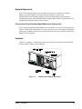


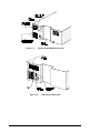
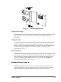
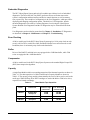


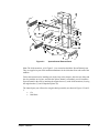
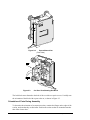

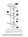
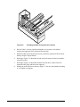
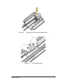
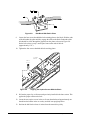


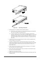
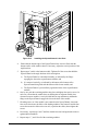
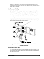

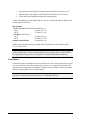


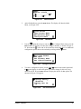
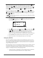
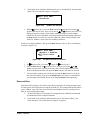


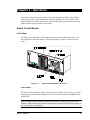
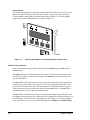
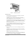

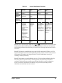
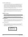

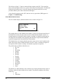
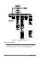

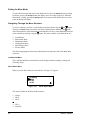

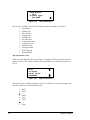

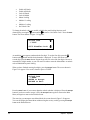
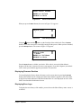


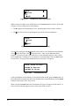
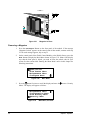

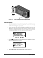

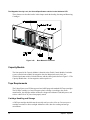


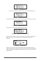
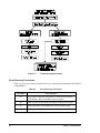
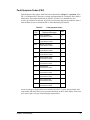
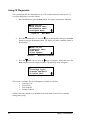


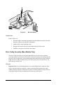
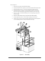


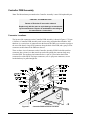
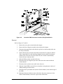


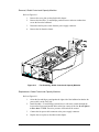

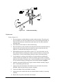
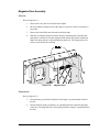
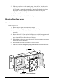


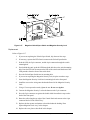


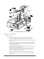
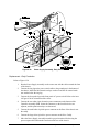


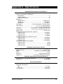

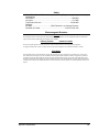


![X-Fire installation instructions - A [IT]](http://vs1.manualzilla.com/store/data/006135060_1-2af8b96d0bc67f8efa4fc02ccbd730a8-150x150.png)