1
LibraryXpress™ Series DLT Library Base Module Models: LXB4X10 and LXB7X10 Installation and User Manual P/N 104126-101 Revision C 1/99 PROPRIETARY NOTICE All information contained in or disclosed by this document is considered proprietary by Overland Data. By accepting this material the recipient agrees that this material and the information contained therein are held in confidence and in trust and will not be used, reproduced in whole or in part, nor its contents revealed to others, except to meet the purpose for which it was delivered. It is understood that no right is conveyed to reproduce or have reproduced any item herein disclosed without express permission from Overland Data. Overland Data provides this manual "as is," without warranty of any kind, either expressed or implied, including, but not limited to, the implied warranties of merchantability and fitness for a particular purpose. Overland Data may make improvements or changes in the product(s) or programs described in this manual at any time. These changes will be incorporated in new editions of this publication. Overland Data assumes no responsibility for the accuracy, completeness, sufficiency, or usefulness of this manual, nor for any problem that might arise from the use of the information in this manual. In May 1993, Overland Data, Inc. acquired the engineering, manufacturing and marketing rights for selected Cipher products. Cipher is now a brand name of Overland Data, Inc. Worldwide Headquarters Overland Data, Inc. 8975 BALBOA AVENUE SAN DIEGO, CA 92123-1599 TOLL FREE: (800) 729-8725 TEL: (619) 571-5555 FAX: (619) 571-3664 SALES TEL: (619) 571-5555 FAX: (619) 571-3664 E-MAIL: [email protected] WWW : http://www.overlanddata.com TECHNICAL SUPPORT TEL: (619) 571-5555 TOLL FREE: (800) 729-8725 FAX: (619) 571-3664 E-MAIL: [email protected] WWW : http://www.overlanddata.com Overland Data, EMEA UNIT 3, ASHVILLE WAY WOKINGHAM, BERKSHIRE RG41 2PL, ENGLAND TEL: +44 (0)118-9898000 FAX: +44 E-MAIL: [email protected] WWW : http://www.overlanddata.com ii (0)118-9891897 CONTENTS CHAPTER 1 - INTRODUCTION.......................................................................... 1 Models................................................................................................................. 1 SCSI Interface Configuration.............................................................................. 2 Data Transfer Rates ...................................................................................... 3 Internal Cabling................................................................................................... 3 Physical Configuration........................................................................................ 4 System Expansion ............................................................................................... 4 Features ............................................................................................................... 5 Control Panel ................................................................................................ 5 Display.......................................................................................................... 6 Power Supply................................................................................................ 6 Tape Cartridge Magazine ............................................................................. 6 Integral Fan Cooling ..................................................................................... 8 Library Robotics ........................................................................................... 8 Bar Code Reader........................................................................................... 8 Advanced Design Features.................................................................................. 8 Embedded Diagnostics ................................................................................. 8 Error Checking.............................................................................................. 9 Buffer............................................................................................................ 9 Compression ................................................................................................. 9 Media Life .................................................................................................. 10 Related Publications.......................................................................................... 10 CHAPTER 2 - INSTALLATION......................................................................... 11 Mechanical Installation ..................................................................................... 11 Desktop Installation .................................................................................... 11 Rack Mount Installation ............................................................................. 12 iii Interfaces and Cabling ...................................................................................... 16 Power Cable ............................................................................................... 17 SCSI Interfaces........................................................................................... 17 Interface Cable Specifications.................................................................... 18 Terminators ................................................................................................ 19 Interface Cable and Terminator Installation............................................... 20 Configuration .................................................................................................... 21 A Configuration Example - Setting the SCSI ID ....................................... 22 Reserved Slots ............................................................................................ 24 Descriptions of Configuration Options ...................................................... 25 Specifying Customer-Unique Device Identification .................................. 27 CHAPTER 3 - OPERATION............................................................................... 37 Front Panel........................................................................................................ 37 Power Switch ....................................................................................... 38 Magazine Security Lock ...................................................................... 38 Unlock/Open Button ............................................................................ 38 Locked Indicator LED ......................................................................... 38 Control Panel.............................................................................................. 38 Indicators ............................................................................................. 39 Buttons ................................................................................................. 40 Display Messages ................................................................................ 42 Power-On Self Test Screen.................................................................. 42 Initialization Screens ........................................................................... 42 Default Screen ..................................................................................... 42 Control Panel Display Modes ........................................................................... 44 The LibraryXpress Menu Structure ........................................................... 44 Entering the Menu Mode............................................................................ 45 Exiting the Menu Mode.............................................................................. 47 Navigating Through the Menu Structure .......................................................... 47 Load/Unload Menu .................................................................................... 47 Show Status Menu...................................................................................... 48 Maintenance Menu..................................................................................... 51 Configure Menu ......................................................................................... 51 Show History Menu.................................................................................... 52 Security Menu ............................................................................................ 52 Displaying Firmware Revision................................................................... 53 Displaying Error Logs ................................................................................ 54 iv Handling the Magazine ..................................................................................... 54 Removing the Magazine ............................................................................. 56 Emergency Magazine Removal .................................................................. 56 Inserting a Magazine Into the Base Module ............................................... 56 Inserting Cartridges Into the Magazine ...................................................... 57 Tape Requirements............................................................................................ 58 Cartridge Handling and Storage........................................................................ 58 Storing Cartridges....................................................................................... 59 If a DLTtape cartridge is dropped .............................................................. 59 Labeling Cartridges .................................................................................... 60 Write Protection.......................................................................................... 60 Loading and Unloading Tapes.................................................................... 61 CHAPTER 4 - MAINTENANCE ......................................................................... 67 Using the Cleaning Cartridge............................................................................ 67 Using the Autoclean Feature ...................................................................... 68 Installing a Cleaning Cartridge................................................................... 68 Running the Cleaning Cartridge ................................................................. 69 Removing the Cleaning Cartridge .............................................................. 71 CHAPTER 5 - TROUBLESHOOTING .............................................................. 73 Diagnosing Problems ........................................................................................ 73 Platform Problems ...................................................................................... 73 General Drive Errors .................................................................................. 73 Error Recovery .................................................................................................. 74 Fault Symptom Codes (FSC) ............................................................................ 75 Using the Demo Submenu................................................................................. 93 APPENDIX A - SPECIFICATIONS ................................................................... 95 APPENDIX B - ACCESSORIES/SPARES/ FRUS........................................... 101 INDEX................................................................................................................... 103 v Figures Figure 1-1 Front View............................................................................................... 5 Figure 1-2 Cartridge Magazine ................................................................................. 7 Figure 1-3 Rear View ................................................................................................ 7 Figure 2-1 Rack Slide Parts..................................................................................... 13 Figure 2-2 Separating a Rack Slide ......................................................................... 14 Figure 2-3 Rear Panel Connectors, Terminator and Cables.................................... 16 Figure 2-4 Default Screen ....................................................................................... 22 Figure 2-5 Main Menu ............................................................................................ 22 Figure 2-6 Configure Menu..................................................................................... 22 Figure 2-7 Set SCSI Submenu................................................................................. 23 Figure 2-8 Set SCSI Submenu Scrolled .................................................................. 24 Figure 2-9 Set Reserved Slots Menu....................................................................... 25 Figure 2-10 Set Unique ID Screen .......................................................................... 28 Figure 2-11 Setting Unique Vendor ID ................................................................... 28 Figure 3-1 Front Panel............................................................................................. 37 Figure 3-2 Control Panel ......................................................................................... 39 Figure 3-3 POST Screen.......................................................................................... 42 Figure 3-4 Initialization Screen.............................................................................. 42 Figure 3-5 Default Screen ....................................................................................... 43 Figure 3-6 Fault Screen ........................................................................................... 44 Figure 3-7 LibraryXpress Menu Structure .............................................................. 45 Figure 3-8 Main Menu ............................................................................................ 46 Figure 3-9 Front Panel Locked Screen.................................................................... 46 Figure 3-10 Show Status Menu ............................................................................... 48 Figure 3-11 Library Status Submenu ...................................................................... 48 Figure 3-12 Drive Status Submenu ......................................................................... 50 Figure 3-13 Map Info Submenu .............................................................................. 50 Figure 3-14 Code Select Submenu .......................................................................... 52 Figure 3-15 Code Accept Submenu ........................................................................ 53 Figure 3-16 Error History Screen............................................................................ 54 Figure 3-17 Magazine in Place................................................................................ 55 Figure 3-18 Tape Magazine with Cartridges Installed............................................ 57 Figure 3-19 Inspecting Leader of DLTtape Cartridge............................................. 59 Figure 3-20 DLTtape Cartridge Write Protection Switch....................................... 60 vi Figure 3-21 Default Screen...................................................................................... 61 Figure 3-22 Main Menu........................................................................................... 61 Figure 3-23 Load/Unload Initial Screen .................................................................. 62 Figure 3-24 Load/Unload ‘From’ Entry Screen ...................................................... 63 Figure 3-25 Load/Unload ‘To’ Entry Screen........................................................... 64 Figure 3-26 Confirmation Screen ............................................................................ 64 Figure 3-27 Load/Unload ‘In Progress’ Screen....................................................... 64 Figure 3-28 Updated Default Screen ....................................................................... 65 Figure 4-1 Reserved Slot Numbering ...................................................................... 69 Figure 4-2 Main Menu............................................................................................. 69 Figure 4-3 Maintenance Submenu........................................................................... 70 Figure 4-4 Cleaning Submenu ................................................................................. 70 Figure 4-5 Cleaning Confirmation Screen............................................................... 70 Figure 4-6 Cleaning In Progress Screen .................................................................. 71 Figure 5-1 Troubleshooting Flow Chart .................................................................. 74 Tables Table 1-1 Data Transfer Rates................................................................................... 3 Table 1-2 Tape Capacities ....................................................................................... 10 Table 1-3 Media Life ............................................................................................... 10 Table 2-1 LibraryXpress Configuration Options..................................................... 33 Table 3-1 Control Panel Button Functions .............................................................. 41 Table 3-2 Tape Specifications by DLT Type .......................................................... 58 Table 5-1 Fault Symptom Codes ............................................................................. 75 vii viii Chapter 1 - Introduction Chapter 1 - Introduction The DLT LibraryXpress™ Base Module is the foundation of an expandable, modular tape library system. The LibraryXpress system is designed for high duty-cycle on-line and near-on-line applications such as hierarchical storage management (HSM). It is a superior performer in high-volume backup and archival service as well. Models The complete model number for any of the LibraryXpress modules follows the pattern shown below: For the sake of brevity, the different tape drives in LXB modules are referenced in the manual according to this example: LXB7110 1 Chapter 1 - Introduction The Base Module contains one or two DLT drives plus a 10-cartridge magazine with a rugged random access loader mechanism. The DLT LibraryXpress Base Module is available in four models: • • • • LXB4110 LXB4210 LXB7110 LXB7210. All models use the high-density DLTtape IV cartridges. DLTtape IV media is rated at over 1,000,000 head passes. All models can also read and write DLTtape III and DLTtape III XT cartridges. Write densities are selectable from the front panel, and under SCSI control from the host. SCSI Interface Configuration The DLT LibraryXpress Base Module may be ordered with a choice of single-ended or differential SCSI-2 interfaces. The LXB4X10, SCSI-2 interface, uses two female, high-density 50-pin D-series connectors per bus. The LXB7X10, Fast/Wide SCSI Interface uses high-density 68-pin connectors. The section on Interfaces in Chapter 2 - Installation describes the available interface options. 2 Chapter 1 - Introduction Data Transfer Rates Table 1-1 Data Transfer Rates Drive Technology Number of Drives Maximum Sustained Native Rate MB/second DLT 4000 DLT 4000 DLT 7000 DLT 7000 1 (LXB4110) 2 (LXB4210) 1 (LXB7110) 2 (LXB7210) 1.5 3.0 5.0 10 Maximum Sustained Native Rate GB/hour 5.4 10.8 18 36 Note: The rates for compressed data are the native rates multiplied by the compression factor, which depends on file content, but averages approximately 2:1. Note: GB/hour rates are maximum and may vary due to the specific characteristics of the data. The SCSI interface for the library robotics is designed for high-speed operation, in anticipation of improvements in drive technology. As faster drives become available, they will be made available for upgrade of the Base Module. Internal Cabling All models are shipped with separate external SCSI connections for the library robotics and each of the drives. These configurations are described in more detail in the section on Interfaces in Chapter 2 - Installation. 3 Chapter 1 - Introduction Physical Configuration All models of the Base Module may be ordered in either rack mount or desktop configuration. For users who start with a desktop configuration and later wish to expand, a conversion kit is available to convert a desktop module to rack mount configuration. Another kit is available for conversion in the opposite direction. See Appendix B - Accessories/ Spares/FRUs for the part numbers. System Expansion A LibraryXpress Base Module may be expanded in capacity or performance or both by adding a Global Control Module and one or more additional LibraryXpress modules in a rack mount configuration. Overland Data’s Smartscale Storage™ architecture enables the robotics in each of the LibraryXpress modules to exchange cartridges by means of the XpressChannel™ pass-through cartridge elevator, and integrates the robotics in the individual modules and the Global Control’s XpressChannel into a single high-performance library robotics system. Contact your Overland Data representative for more information about expanded LibraryXpress systems. 4 Chapter 1 - Introduction Features Figures 1-1, 1-2, and 1-3 identify some of the external features of the LXB4X10 and LXB7X10 Base Modules. Figure 1-1 Front View Control Panel The control panel features a 4-line by 20-character backlit LCD display, four LED indicators and four buttons. The buttons enable the operator to navigate through the menu structure to select and display operating modes, device status, diagnostic and maintenance functions, device history and error statistics, and system configuration. The functions of the control panel are described in detail in Chapter 3 - Operation. 5 Chapter 1 - Introduction Display The backlit 4-line by 20-character control panel display provides a highly intelligible display of drive and loader status, menu choices and error messages. The scrolling feature greatly expands the amount of information available to the operator. Power Supply The AC Power switch is located on the front panel of the module. The autoranging power supply will adjust automatically to either of two operating voltage ranges. The ranges are 104-120 VAC and 200-254 VAC. The power supply is capable of operating at 50 or 60 Hz without requiring any modification. AC power is supplied to the power supply by a single cable which can be plugged into any properly grounded outlet. Tape Cartridge Magazine The ten-cartridge magazine is removable from the front panel, but is protected from tampering by a key-operated Magazine Security Lock which must be unlocked before the magazine can be removed. The rugged polymer magazine fits into an extruded track, which assures precise positioning with respect to the library robotics. A tape magazine is shown in Figure 1-2. Insertion and removal of the magazine is described in Chapter 3 - Operation. 6 Chapter 1 - Introduction Figure 1-2 Cartridge Magazine SCSI In terfac e F an P ow er C on nector G lobal C ontrol Interfa ce (trace port o n sta nd alo ne co nfigura tion) Figure 1-3 Rear View 7 Chapter 1 - Introduction Integral Fan Cooling The rear panel contains a single forced-air cooling fan. The fan prevents the drive and robotics electronics, the motors, and the power supply from overheating. Library Robotics The Base Module library robotics can load any of the cartridges from its removable 10-cartridge magazine into either of two DLTtape drives. Models LXB4110 and LXB7110 have only one drive per module. Bar Code Reader The optional bar code reader is mounted on the cartridge shuttle. It reads bar code labels attached to each cartridge and maintains the bar code data in memory as part of the library inventory records. An upgrade kit to add the bar code reader is available. See Appendix B - Accessories/ Spares/FRUs for the part number. Advanced Design Features The DLT LibraryXpress incorporates many significant improvements in tape drive and library design. The robotics design utilizes Overland Data’s Mainframe-Class™ Library Robotics, known for ruggedness and reliability. Importantly, the Library is designed to use highly reliable DLTtape IV media. DLTtape IV is rated at over 1,000,000 head passes. DLTtape IV cartridges are used by all DLT4000 and DLT7000 drives in both multimodule systems and in standalone libraries. Embedded Diagnostics The DLT LibraryXpress Base Module provides three levels of embedded diagnostics: 1. The Power-On Self Test (POST) - Performs various verification tests on the processor’s host interface and device control functions, as well as memory tests, at power-up. 8 Chapter 1 - Introduction 2. User Diagnostics - Let you change configuration options, and exercise the robotics under the Demo menu to assist in diagnosing faults. 3. CE Diagnostics - Provides more advanced diagnostics to Customer Engineers (CE) for servicing the Base Module. Both the User Diagnostics and the CE Diagnostics can be selected from the front panel. Diagnostics are described in greater detail in Chapter 2 - Installation (configuration diagnostics) and Chapter 5 - Troubleshooting (remaining user diagnostics). Error Checking To ensure data integrity, the drives in the LXB4X10 and LXB7X10 Base Modules apply: • • • • Reed-Solomon error-correction codes of 16 KB with every 64 KB of user data A 64-bit cyclic redundancy code (CRC) A 16-bit error-detection code (EDC) for each 4 KB of recorded data An end-to-end 16-bit CRC for each user record. Buffer Each drive in an LXB4X10 is equipped with a 2-MB data buffer. Each drive in an LXB7X10 is equipped with an 8-MB data buffer. Compression The drives in the DLT LibraryXpress Base Module use the standard Digital Lempel-Ziv (DLZ) data compression algorithm. 9 Chapter 1 - Introduction Capacity A single Base Module with its ten-cartridge magazine offers formatted capacities as shown below. When the LXB4X10 uses DLTtape III or IIIXT cartridges, its capacity is limited accordingly. Table 1-2 Tape Capacities Capacity A per Cartridge Full Magazine CompressedB Drive Model DLTtape III 10 GB 200 GB LXB4X10 DLTtape III XT 15 GB 300 GB LXB4X10 DLTtape IV 20 GB 400 GB LXB4X10 DLTtape IV 35 GB 700 GB LXB7X10 Cartridge A Native capacities, uncompressed. B Maximum capacities given assume average 2:1 compression. Actual compression will vary with file content. The native capacity for a full magazine is ten times the native capacity per cartridge. Media Life Table 1-3 Media Life DLTtape Type Head Passes Tape Life III IIIXT IV 500,000 1,000,000 1,000,000 20 Years 30 Years 30 Years Related Publications For additional information about the LXB4X10 and LXB7X10, and about the DLT LibraryXpress System product line, refer to the following publications: • DLT Base Module Service Manual, P/N 104127-101 • DLT Base Module SCSI Specification, P/N 104134-101 • DLT LibraryXpress System Installation and User Manual, P/N 104139-101 • DLT LibraryXpress System Service Manual, P/N 104140-101. 10 Chapter 2 - Installation Chapter 2 - Installation There are three major steps to complete installation of the DLT LibraryXpress Base Module: • • • Mechanical installation Cabling Configuration. Mechanical installation consists of installing the module in a rack (for rack mounted units). No mechanical installation is required for desktop models. Cabling consists of connecting the module to the host interface and terminating the busses properly. Configuration consists of using the Configure Menu to customize the configuration options to your particular application if required. The default settings are often appropriate, and customization is not needed. Mechanical Installation Follow the directions in the shipping container to unpack the module and place it in the desired physical location. Save the packing materials for reuse in case you need to send the module to Overland Data for repairs. If the Base Module is to be added to an existing LibraryXpress system, please refer to the LibraryXpress System Installation and User Manual for information on mechanical installation. Desktop Installation There is no user assembly required. Place the drive on a stable horizontal surface with at least 2” clearance behind it to allow free flow of cooling air from the fan. 11 Chapter 2 - Installation Note: If the Base Module is to be added to an existing LibraryXpress subsystem, or if you are expanding an existing desktop Base Module by adding a Global Control Module and additional LibraryXpress modules, all modules must be mounted in a rack. A kit is available to convert your existing desktop model for rack mounting. See Appendix B for ordering information. Rack Mount Installation The Base Module can be mounted in a standard 19-inch EIA/RETMA rack with a depth of 24 to 30 inches. The rack mount version is shipped with two rack slides installed. If the Base Module is to be added to an existing LibraryXpress subsystem, please refer to the LibraryXpress System Manual for information on mechanical installation. Note: The cooling fan at the rear of the drive must not be obstructed when the drive is installed in the rack. It is advisable to allow two inches of clearance behind the rear panel of the module. CAUTION! MAKE CERTAIN THAT WHEN THE MODULE IS FULLY EXTENDED THAT A FORCE OF 20% OF THE RACK WEIGHT, BUT NOT MORE THAN 57 LB. APPLIED IN ANY DIRECTION BUT UPWARDS DOES NOT CAUSE THE RACK TO OVERBALANCE. VORSICHT: BITTE BEACHTEN, DAß WAHREND DAS MODUL AUSGEZOGEN SIND, LEDIGLICH EINE ZUSÄTZLICHE LAST VON MEHRALS 20% DES GESTALLGEWICHTES, ABER NICHT MEHR ALS 26 KG IN ALLE RICHTUNGEN AUßER NACH OBEN, DIE STABILITÄT DES GESTALLS GEFÄHRDET. 12 Chapter 2 - Installation Note: All of the screws, washers and nut-plates required for rack mounting are supplied with the Base Module. The slides must be fastened to the front rails of the rack using four 10-32 low-profile screws and the nut-plates provided. Two 10-32 clip nuts are provided to engage the captive screws on the front panel. Follow the instructions below to install the LibraryXpress Base Module into a rack. You will need a #2 Phillips screwdriver and a flathead screwdriver. Refer to the figures as directed. Note: The left and right slides are alike, so there is no risk of confusing the parts on re-assembly. Figure 2-1 Rack Slide Parts 13 Chapter 2 - Installation 1. Refer to Figure 2-1 to identify and orient the parts of the slides. The slide is attached to the Base Module enclosure by means of three screws through the inner slide. 2. Refer to Figure 2-2. Separate each set of slides as follows: a) Pull the outer slide toward the rear, along with the intermediate slide until the inner slide lock engages the intermediate slide. b) Continue to pull the outer slide towards the rear until the outer slide lock engages the intermediate slide. Press down on the inner slide lock to permit the intermediate slide to continue to move toward the rear. Continue to move the outer and intermediate slides toward the rear until they are separated from the inner slide. Figure 2-2 Separating a Rack Slide 14 Chapter 2 - Installation 3. Locate the screw holes in the front and rear rails of the cabinet or equipment rack where the drive is to be installed. 4. Loosely assemble a mounting bracket to each outer slide, using two 10-32 screws with washers and a nut-plate for each. Select slots in the mounting brackets so the length of the assembly equals the distance between the front and rear rails of the rack. 5. Fasten each outer slide behind the front rail of the rack using two 10-32 low-profile screws with washers and one nut plate. 6. Fasten each of the mounting brackets to the front of the rear rail of the rack using two 10-32 screws and one nut plate. 7. Tighten the screws installed in step 4. 8. If they are not already locked, pull the intermediate slides toward the front (out of the rack) so that they lock in the extended position. 9. Note: This step should be performed by two people. In front of the rack, lift the module to its installed height. Engage the inner slides mounted on the module with the intermediate slides protruding from the rack, and slide the module toward the rack until the inner slide lock engages the intermediate slide. This leaves the entire module protruding from the rack, locked in position, supported by slides. 10. Press inward (toward the module) on each of the inner slide locks to permit the intermediate slides to move toward the rack. 11. Slide the module in and out several times, ensuring that the inner and outer slide locks engage, and that the module does not bind against the slides. 12. If binding occurs, loosen the four screws that secure the slides to the front rails and the four screws that secure the slides to the rear rails. 13. If necessary, repeat steps 11 and 12 until the module does not bind against the slides. 15 Chapter 2 - Installation 14. If the rails on your rack are not threaded, install a clip nut on each front rail at the height of the captive screws on the front panel of the Base Module. If the rails on your rack are threaded, skip this step. 15. Slide the Base Module into the rack, and tighten the captive screws. Interfaces and Cabling Refer to Figure 2-3. If the Base Module is to be installed alone, that is, not as part of a multi-module subsystem, the connections required are the SCSI connection to the host, and the AC power connection. The Global Control interface connector is used only when the module is used in combination with other modules as part of a DLT LibraryXpress subsystem. If the Module is to be added to an existing DLT LibraryXpress subsystem, please refer to the DLT LibraryXpress System Installation and User Manual for information on cabling. Figure 2-3 Rear Panel Connectors, Terminator and Cables Shown with SCSI Jumpers for Daisy-Chained Configuration 16 Chapter 2 - Installation Power Cable The AC power cable is a standard grounding AC cable which attaches to a connector on the rear panel. Connect the cable to the connector on the module, and connect the other end to a reliably grounded AC outlet or rack power outlet. To maintain product safety compliance, use a power cord with a suitable electrical rating that is approved for the country where the product is used. In the US, use a UL listed cord; in Canada, a CSA certified cord; and in Europe, use a Harmonized cord marked <HAR> or a nationally certified cord. Note: After connecting the LibraryXpress Base Module to your AC source, It is a good practice to power up and test the module before connecting to the host computer. SCSI Interfaces The DLT LibraryXpress Base Module may be ordered with a choice of single-ended or differential SCSI-2 interfaces. The LXB4X10, Fast SCSI-2 interface, uses two female, high-density 50-pin D-series connectors per bus. SCSI-2 cables and terminators are secured to the connectors by spring loaded latches. The LXB7X10, Fast/Wide SCSI Interface uses high-density 68-pin connectors. Fast/Wide SCSI cables and terminators are secured to the connectors by jackscrews. Both of these SCSI interfaces are provided with independent bus wiring. That is, each drive has a separate bus, with a pair of SCSI connectors, and the library robotics has a separate bus, with a pair of SCSI connectors. In this configuration, there are six SCSI connectors on the rear panel. In the singledrive models, the connectors labeled DLT 2 are inactive. SCSI jumper cables can be used for daisy-chained applications. Each of the drives and the library robotics are separate SCSI devices. Each requires a unique SCSI address if they are daisy-chained on the same bus. 17 Chapter 2 - Installation A terminator of the proper type (single-ended or differential) must be installed on each unused connector of each bus, as explained below in the section headed ‘Interface Cable and Terminator Installation. Figure 2-3 shows the SCSI cable, connectors and bus terminator used on the module. In order to connect the module to a host computer system, the host system must have at least one SCSI controller and the appropriate driver software. Your Technical Support representative is available to answer your questions about installation procedures for specific host systems. Before cabling the system, see the recommended SCSI cable specifications in the following section. Also, see the section on Interface Cable and Terminator Installation later in this chapter. Interface Cable Specifications The DLT LibraryXpress is a high-performance system. To avoid degradation of performance, use the highest-quality interface cables. The detailed requirements for SCSI cables are set forth in ANSI X3.131-1994. It is recommended that all SCSI cables used with the DLT LibraryXpress Module meet at least the following requirements: • Shielded or double-shielded, as required to meet EMI specifications • Impedance match with cable terminators of 132 ohms, ideally • Characteristic impedance between 90 and 132 ohms, required • 25-pair twisted-pair should be used • Each end of the twisted pair ground must be connected to chassis ground • The maximum cable length for a single-ended Fast SCSI bus is 9.8 feet (3 m)* • The maximum cable length for a differential Fast SCSI bus is 82 ft. (25 m)* • Cables of different impedances should not be used together. 18 Chapter 2 - Installation * When calculating the overall length of the bus, be sure to consider both the run length to the host and the internal cabling of the module. Nominal lengths are listed below: Base Module: LXB4X10 DLT1 DLT2 LXB7X10 DLT1 DLT2 SCSI Jumper Library (Both units) 19 inches (48 cm) 27 inches (69 cm) 17 inches (43 cm) 26 inches (66 cm) 12 inches (30 cm) 36 inches (91 cm) Additional specifications to assure the highest SCSI performance can be found in ANSI X3.131-1994 or later. Note: This equipment has been tested for electromagnetic emissions and immunity using good quality shielded cables. The use of unshielded cables, poor quality cables or other variances from good practice may result in noncompliance with national and international rules. Terminators A terminator must be installed on the drive if the drive is to be used at either end of a SCSI bus, such as the first or last device along a daisy-chain, or as a single SCSI peripheral. The appropriate type and quantity of terminator is shipped with your module. It is packaged in the accessory bag that arrives with the module. Notes: 1) It is important to use only differential terminators on a differential SCSI bus; 2) Active terminators are strongly recommended for single-ended applications. 19 Chapter 2 - Installation Note: This equipment has been tested for electromagnetic emissions and immunity using good quality shielded terminators. The use of unshielded terminators, poor quality terminators, or other variances from good practice may result in non-compliance with national and international rules. Interface Cable and Terminator Installation In the interest of clarity, let us assume that the incoming SCSI bus will be connected to the left of a pair of parallel connectors, and that the terminator or the outgoing SCSI bus will be connected to the right of a pair of connectors. To properly cable the drive: 1. Make sure that your host system has appropriate SCSI interface card or cards and software drivers installed. Note whether the interface is single-ended or differential. 2. Inspect the Library and the terminator to determine whether they are single-ended or differential type to match your system. SCSI terminators should be clearly marked single-ended or differential. 3. Determine whether the module’s elements (DLT 1, DLT 2, Library) are to be used with separate SCSI buses or daisy-chained on a single SCSI bus. (Refer to figure 2-3.) If daisy-chained, make the necessary connections among the connectors on the module. That is, right connector of Library to the left connector of DLT1, and if there are two drives, the right connector of DLT 1 to the left connector of DLT 2. This leaves you with the left Library connector as an incoming SCSI connector, and the right DLT 2 (or DLT 1) connector as an outgoing SCSI connector. 4. Determine whether the module is to be connected in daisy-chain fashion with other devices. • If not used in a daisy-chain, install the terminator in the outgoing SCSI connector. In a single-drive module, this will be the right DLT 1 connector, as the connectors marked “DLT 2” are not active. Connect the host cable at the incoming SCSI connector, the left Library connector. 20 Chapter 2 - Installation • If used in a daisy-chain, and the module is the last device of the chain, install the terminator in the outgoing SCSI connector. If the module is not last, do not use the terminator. Connect the cable for the next device in the chain to the outgoing SCSI connector. Connect the host cable or the cable from the preceding device to the incoming SCSI connector, the left Library connector. 5. Make sure that each cable you use meets the specifications listed earlier in this chapter. 6. Measure the cable length to connect the module to the computer system. 7. Be sure that the length of the entire bus falls below the maximum permissible length given in the section on SCSI cable specifications. Configuration The LibraryXpress Base Module is designed with several configuration options, each offering multiple settings to support a variety of applications and platforms. The setting of each option is stored in non-volatile memory in the module. For most applications, you will not need to change the factory default settings. If you need to change the configuration, go on to the next section. If you are uncertain whether you need to change a setting, contact your Technical Support representative. To change settings, you need to use the Control Panel. For an overview of how the Control Panel works, and a description of the functions of the buttons, indicators and display, refer to the sections titled Entering the Menu Mode, Exiting the Menu Mode, and Navigating Through the Menu Structure in Chapter 3 - Operation. The settings can be changed using the procedure described below under How to Customize Configuration. Before changing any configuration settings, consult your host system documentation to determine which settings may need to be changed. 21 Chapter 2 - Installation A Configuration Example - Setting the SCSI ID 1. Turn the system on. Wait until the Power-On Self Test terminates and the default screen appears on the display. Figure 2-4 shows a typical default screen. Yours may vary depending on the number of drives in your system. '/7ìãý1Pý7BQF '/7ëãý1Pý7BQF /PBEFSý,EMF ìX_ _ _ _ _ _ _ _ _ _W Wìí Figure 2-4 2. Default Screen At the Default Screen, press the Enter button. The display will show the Main Menu, as in Figure 2-5. X/PBEî8OMPBE ý6IPXý6UBUVTý0FOV ý0BJOUFOBODFý0FOV ý&POGJHVSFý0FOVýýýý ý&POGJHVSFý0FOV ýýýý† † Figure 2-5 3. Main Menu Press the T button three times to move the X to Configure Menu, then press the Enter button. The display will show the Configure Menu, as shown in Figure 2-6. Note that the † at the end of the fourth line means that there are additional configuration options that can be reached by scrolling with the T button. X6FUý'BUBý)PSNBU ý6FUý6&6, ý6FUý/JCSBSZý0PEF ý6FUý(MFNFOUý%BTF ý6FUý(MFNFOU ý%BTFýý ýý† Figure 2-6 Configure Menu 22 Chapter 2 - Installation 4. To select a configuration option, press the S or T button on the control panel until the X on the display is next to the option you want to change. In this case, let us choose Set SCSI. Press the Enter button to display the choices for that option. The submenu in Figure 2-7 appears. X/JCSBSZý3BSJUZã ýýó(OBCMFE ý/JCSBSZý%VTý,'ã ýýóçýýýýýýýýýýýýýýý † Figure 2-7 Set SCSI Submenu Note: Take a moment to look closely at the submenu in Figure 2-7. Note that the X on the display is next to line 1, and that line 2 is indented. This tells you that Figure 2-7 is a two-tiered menu. The S and T buttons work on two levels in this kind of menu, which is typical of many submenus of the Configure Menu. The first level is as follows: If you press the T button, the X moves to line 3. If you press the S button, the X moves back to line 1. If you press the Enter button while the X is next to line 1 (or line 3), the S and T buttons operate on the second level. You can tell because the X moves next to line 2 (or line 4), and a † appears at the end of line 4, indicating that there is a list of settings that can be scrolled using the S and T buttons. The † at the end of line 4 means that there are other items that can be displayed by scrolling, using the T button repeatedly. 23 Chapter 2 - Installation 5. Note that the Library SCSI ID is set to 6. Suppose you want to set the DLT1 bus ID to 4. With the X next to line 1, press theT button repeatedly until the display scrolls as shown in Figure 2-8: '/7ìý%VTý,'ãýýýýý… X'/7ìý%VTý,'ãýýýýý ýýóè ýýýýýýýýýýýýýýýýýý† ýýýýýýýýýýýýýýýýýý Figure 2-8 Set SCSI Submenu Scrolled 6. With the X next to line 1, press the Enter button The X moves to line 2 and the † remains at the end of line 4, and a … appears at the end of line 1. Now you can use the S and T buttons to scroll line 2 to display the possible settings. Scroll downward so that 4 is displayed, then press the Enter button to save the new selection. An ó indicates that it is the current selection. 7. Press the Escape button repeatedly until the submenu in Figure 2-6 reappears. 8. Repeat this procedure for each configuration option you want to change. Note: Some configuration changes only take place after you reboot. To reboot the system, go to the Maintenance Menu. Press the T button until Reboot Module is selected, then press the Enter button. Reserved Slots Some host software imposes size limits on tape library magazines for licensing purposes, and will not operate with a library that exceeds the licensed size. This configuration option enables you to withdraw some of the slots in the LibraryXpress System from use as storage slots in order to meet licensing requirements or to reserve a slot for use with the AutoClean feature. 1. As shown in Figures 2-4 through 2-6, navigate from the Default Screen through the Main Menu to the Configure Menu. 24 Chapter 2 - Installation 2. Scroll down on the Configure Menu until you see ‘Set Reserved Slots,’ and select that option. The screen shown in Figure 2-9 appears. X5FTFSWFEý6MPUTã ýýóí Figure 2-9 Set Reserved Slots Menu 3. With the X next to line 1, press the Enter button The X moves to line 2, a † appears at the end of line 4, and a … appears at the end of line 1. Now you can use the S and T buttons to scroll line 2 to specify the number of slots to be reserved. Scroll to the desired number, then press the Enter button to save the new selection. 4. Press the Escape button repeatedly to return to the Default Screen. Descriptions of Configuration Options The items available on the Configuration Menu are as follows: Set Data Format: This setting lets you: 1. Set the data format to: • • • • • • • Auto Selection THZ01 THZ02 DLT2000 DLT2000XT DLT4000 DLT7000. 25 Chapter 2 - Installation 2. Enable or disable data compression—Compression cannot be enabled when either THZ01 or THZ02 format is in use. This setting applies to the next or the currently loaded cartridge only. An unload command returns to the default. This setting does not display the format of the loaded tape. Use the Show Status Menu for this purpose. The defaults are Auto Selection for both density and compression. Set SCSI: This setting lets you: 1. Enable or disable the robotics SCSI bus parity checking 2. Set the SCSI addresses of the drives and the robotics. The defaults are: • • • • Library Parity Library Bus ID DLT 1 Bus ID DLT 2 Bus ID = = = = ON 6 4 5 Set Library Mode: This setting lets you switch the robotics operating mode between Random or Sequential. • Random is the normal operating mode which affords complete host control of the robotics. Random is the default. • Sequential mode is locally controlled. Sequential operations begin by loading a cartridge into DLT1 with the operator panel. The LibraryXpress monitors the status of DLT1, and when the cartridge is unloaded by the host, it returns the cartridge to the magazine, then loads the next cartridge in magazine numerical order. This operation continues to cycle until all of the cartridges have been loaded, or until an empty slot is encountered. When you select Sequential, an additional Sequential Mode option appears that lets you select Normal or Recirculate options. Normal option operates as described above. In Recirculate mode, instead of stopping after the cartridge in the last slot has been unloaded by the host, the operation continues by loading the cartridge in Slot 1. Recirculation will continue until an empty slot is encountered. The default for Sequential Mode is Normal. 26 Chapter 2 - Installation Set Element Base: This setting lets you set the base addresses of each of the SCSI elements of the module. In order to identify sources and destinations in SCSI commands to the robotics, the LibraryXpress is divided into elements, each of which is assigned a separate designator or element address: • • • The Transport Element is the robotics mechanism itself The Storage Elements are the ten slots in the magazine The Transfer Elements are the drive(s). The LibraryXpress reports these settings in response to the SCSI Mode Sense command, in the Element Address Assignment Page. The defaults are: • • • Transport Element = 0000 Storage Element Base = 0001 Transfer Element Base = 00F0 (DLT 1). Set Identification: This setting enables you to specify the response of the library robotics to the SCSI Inquiry command in the Vendor ID and the Product ID fields. The defaults are: • • Vender ID = OVERLAND Product ID = LXB. Specifying Customer-Unique Device Identification The Identification option in the Configuration Menu lets users identify their LibraryXpress as a device in their network computer system. Specific settings lets you specify a unique vendor ID and product ID. These unique IDs can be of particular value where certain types of host software recognize only a limited set of device names. The custom ID capability lets LibraryXpress respond as host-recognizable devices and communicate properly. To specify a unique vendor ID/product ID: 1. From the Main Menu, select Configuration Menu. The screen lists the configuration options. 27 Chapter 2 - Installation 2. Use the X button to scroll down to the Set Identification option, and press the Enter key. This screen appears: X9FOEPS ,' ó29(5/$1' 3SPEVDU ,' ó/;% Figure 2-10 Set Unique ID Screen 3. Position the button next to Vendor or Product ID, and press the Enter key. 4. The T button drops to second menu tier and the screen displays the first of a list of ID options. 5. Scroll through the list to display <Vendor or Product Unique>, and press the Enter key. (If you select, for example, Vendor Unique, the following screen appears): X8OJRVF 9FOEPS ,' K K … † Figure 2-11 Setting Unique Vendor ID The screen shows a blank space between quotation marks with a blinking cursor beneath the first character position. 6. Use the T and S buttons to display a character in the first position. The S button scrolls through: a) b) c) d) an upper case alphabet digits 0-9 a lowercase alphabet a series of special characters. 7. The T button scrolls backward through the series. 28 Chapter 2 - Installation 8. Press the Enter key to accept the first character and advance the cursor to the next position. 9. Continue entering as many as eight characters. 10. Press Escape when you are finished. 11. Press Enter to accept your ID. Set Date: Lets you set the module’s calendar. Set Time: Lets you set the module’s clock. Set Baud Rate: Lets you set the data transmission rate of the module’s trace port. This function is intended for use by Customer Engineers only. The default is 38400 bits/sec. Set Serial number: This setting lets you alter the library’s serial number as stored in the unit. The library’s robotics reports these settings in response to the SCSI Inquiry command, in the Unit Serial Number Page. Set Unload Mode: This setting determines whether a SCSI Move Medium command is interpreted as implicit or explicit. If implicit, the module, in response to a Move Media command, unloads a drive before attempting to move a cartridge from that drive. If explicit, the host must issue a SCSI Unload command to a drive before each Move Medium command that removes a cartridge from that drive. The default is Implicit. Set Autoclean Mode: This setting allows you to enable an automatic cleaning cycle which operates as part of the cartridge unload sequence whenever the Use Cleaner LED comes on. To use this option, you must reserve a slot for a cleaning cartridge using the Reserved Slots option. The default is Disabled. 29 Chapter 2 - Installation Set Negotiation: This option offers two choices: 1. Initiate Synchronous Negotiation 2. Set Transfer Rate. Initiate Negotiation, if set, allows the LibraryXpress to initiate SCSI Synchronous Negotiation with the host (the default is No). The LibraryXpress always responds to host-initiated negotiation. Set Transfer Rate can be set to 10 Mbytes/sec, 5 Mbytes/sec or Asynchronous. The default is 10 Mbytes/sec. Set Reserved Slots: Some host software imposes size limits on tape magazines for licensing purposes, and will not operate with a library that exceeds the licensed size. This setting enables you to withdraw from use a specified number of the slots in the magazine. At least one reserved slot is required in order to use the Autoclean option. Set Special Configuration: This option lets you access a submenu of special configuration settings described below: 1) Mode PG 1F Length Enables you to choose between two lengths of the Mode Sense/Select Device Capabilities Page (SCSI Page 1Fh), which are 14 bytes and 18 bytes, to accommodate different SCSI device implementations of this page. The default is Short. 2) Model Number Enables you to change the model number information displayed on the initial screens. You can choose between OVERLAND ‘LX - - - - - -,’ a blank line, DIGITAL TL89X, ‘IMATION DLT- - - - -,’ and a vendor unique designator. The default is ‘OVERLAND LX - - - 3) TUR Reporting Enables you to set the module to report Good status in response to a SCSI Test Unit Ready command when the module is in the Sequential Mode. Ordinarily, the module returns Not Ready status when in the Sequential Mode. This is needed because some software is unable to issue a Mode Select command to terminate Sequential Mode when the TUR command returns Not Ready. Possible settings are Custom, which returns Good when in Sequential Mode, and Standard, which returns Not Ready in Sequential Mode. The default is Standard. 30 Chapter 2 - Installation 4) Init. Elem. Status Enables you to specify the module’s response to the SCSI Initialize Element Status command. The possible settings are No Inventory, Force Inventory, and Force Label Scan. The default is No Inventory. 5) Unit Attn. Report Enables you to specify the format of the Unit Attention report. If set to All, the unit reports all unit attention conditions in sequence; if set to One, the unit reports only the highest priority condition. 6) Alternate Config. Enables you to configure the library as a standalone unit or a slave unit when used with a Global Controller. 7) Element Based Enables the display of each SCSI element in the unit to begin with either zero or one. This affects only the front panel display, not the actual SCSI element addresses. 8) Label Size Enables you to limit the length of the bar code label reported in the response to the SCSI Read Element Status command. It does not affect the front panel Bar Code Info display of bar code label contents. This option is to accommodate software that requires that bar code labels be less than eight characters in length. The possible settings are 1 through 8. The default is 8. 9) Label Alignment Allows you to set the alignment of the bar code label information reported in the response to the SCSI Read Element Status command. The settings are Left and Right. When used in conjunction with the label size option above, it can strip unwanted trailing characters (Left alignment) or unwanted leading characters (Right alignment). The default is Left alignment. 10) Abort Move Status Enables you to specify the module’s response if it receives a SCSI Reset or Abort command while a Move Medium command is in progress. Depending on this setting, during execution of the Move Medium command, the module will return either Busy or Not Ready in response to the SCSI Reset or Abort commands. The default is a Busy response. 11) AutoClose Enables you to enable or disable the automatic closing of the magazine door. The default is Enabled. 31 Chapter 2 - Installation 12) Door Open Response Enables you to determine the response to a SCSI command when the magazine door is open. The responses are Ready (default) and Not Ready. 13) SCSI Mode Lets you specify the appropriate SCSI command set for your LibraryXpress model. The choices are SCSI-2 (default) or SCSI-3. 14) Post Recovered Error Setting this parameter enables the reporting of TapeAlert informational exception conditions with a Recovered Error sense key, when the Method of Reporting Information Exceptions (MRIE) field is set to a value of 0x3 in Mode Page 1Ch, or if the TapeAlert Mode option is set to Rec. Error (cnd). The default is Disabled. 15) TapeAlert Mode This option specifies the conditions that TapeAlert data will be logged and reported. Select: • Logging Disabled to inhibit the logging feature. • No Exceptions if the device should not report information exceptions. • Unit Attention if the device should report information exceptions with a Unit Attention sense key and an ASC/ASCQ of 5D/00. • Rec. Error(cnd) if the device should report information exceptions with a Recovered Error sense key and an ASC/ASCQ of 5D/00, if Recovered Error Reporting is enabled. • Rec. Error(unc) if the device should unconditionally report information exceptions with a Recovered Error sense key and an ACS/ASCQ of 5D/00. • No Sense if the device should report information exceptions with a No Sense sense key and an ASC/ASCQ of 5D/00. • On Request if the device should report information exceptions with a No Sense sense key and an ASC/ASCQ of 5D/00, only in response to an unsolicited Request Sense command. The default is Logging Disabled. Set Default: This option resets all of the preceding configuration options to their factory defaults. Submenu options are ODI Defaults and DEC Defaults. 32 Chapter 2 - Installation Table 2-1 shows the configuration items for the DLT LibraryXpress System. The item names are shown in the first column, while variations or components of the items appear in the second column. The specific settings available for any item are shown in the third column, with the default selection appearing in bold text. Note: The settings and options listed in this table may vary among different models and different firmware levels of the DLT LibraryXpress System. Table 2-1 LibraryXpress Configuration Options Item Name Item Component Configuration Setting Set Data Format Density DLTn Auto Selection, THZ01, THZ02, DLT2000, DLT2000XT, DLT4000, DLT7000 Auto Selection, On, Off Compression Set SCSI Library Parity Library Bus ID Enabled, Disabled 0, 1, 2, 3, 4, 5, 6, 7 (8, 9, 10, 11, 12, 13, 14, 15 wide only) 0, 1, 2, 3, 4, 5, 6, 7 (8, 9, 10, 11, 12, 13, 14, 15 wide only) 0, 1, 2, 3, 4, 5, 6, 7 (8, 9, 10, 11, 12, 13, 14, 15 wide only) DLT1 Bus ID DLT2 Bus ID Set Library Mode Not available on LXG Library Mode Random, Sequential DLT1, Sequential DLT2, Sequential Split Sequential Mode Normal, Recirculate (doesn’t show if Random) Set Element Base Transport Storage Transfer Import / Export 0x0000 0x0001 0x00F0 0x00E0 (Not available on standalone) Set Identification Vendor ID OVERLAND, EXABYTE, DEC, 33 Chapter 2 - Installation Item Name Item Component Configuration Setting Quantum, <Vendor Unique> Product I: LXB, LXG, LXS, EXB-210, EXB-440, EXB-480, TZ Media Changer, TL800 (C) DEC, <Vendor Unique> Set Date Day Month Year Set Time Hour Minute Set Baud Rate Baud Rate 2400, 9600, 19200, 38400, 57600, 115200, Auto Set Serial Number Serial Number “9999999999” Set Unload Mode Unload Mode Implicit, Explicit Set AutoClean Mode AutoClean Mode Disable, Enable Set Negotiation Mode Negotiation Mode Transfer Rate Do Not Initiate, Initiate Sync 10Mb/sec, Sync 5Mb/sec, Asynch. Only Set Mail Slot Mail Slot Emul Disabled, Module X Enabled Set Reserved Slots Reserved Slots 0,1 - X (X = one less than total slots available) Set Special Config. Mode Page 1F Length Short (0x0E), Long (0x12) Model Number Overland LX____ , Blank Line, Digital TL89X, Imation DLT_____<Vendor Unique> Standard, Custom TUR Reporting 34 Chapter 2 - Installation Item Name Set Default Item Component Configuration Setting Init. Elem. Status Unit Attn. Report Alternate Config. Element Based Label Size Label Align Abort Move Status AutoClose Door Open Response SCSI Mode Post Recv’d Error TapeAlert Mode No Inventory, Force Inventory, Force Label Scan All, One Standalone, Slave One Based, Zero Based 1-8 Left Align, Right Align Busy, Not Ready Enable, Disable Ready, Not Ready SCSI-2, SCSI-3 Disabled, Enabled Logging Disabled, No Exceptions, Unit Attention, Rec. Error (cnd), Rec. Error (unc), No sense, On Request Set Default ODI Defaults, DEC Defaults 35 Chapter 2 - Installation 36 Chapter 3 - Operation Chapter 3 - Operation Front Panel The front panel includes the power switch, the magazine door, the Magazine Security Lock, the Unlock/Open button with its Locked indicator, and the control panel which has buttons, a display and indicators. Figure 3-1 shows the front panel. Figure 3-1 Front Panel 37 Chapter 3 - Operation Power Switch The power switch controls the supply of AC power to the module. It is set into a recess in the front panel to prevent accidental operation. Press 4#to turn the module ON and 3 to turn the module OFF. Magazine Security Lock The Magazine Security lock is an electronic switch that prevents unwanted removal of the magazine. The switch is actuated by a key and can be placed in a locked or unlocked position. When set to the locked position the switch disables the Unlock/Open button. Unlock/Open Button When the Magazine Security Lock is switched to the unlocked position, use this button to disengage the magazine locking mechanism and allow removal of the magazine. The button has no effect when the Magazine Security Lock is locked. Locked Indicator LED This LED indicates whether the magazine is locked inside the module or is freely removable. The LED illuminates after you insert a magazine into the module and it locks into position. The LED continues to glow steadily while the magazine is locked inside the module. When you press the Unlock/Open button, the LED blinks momentarily. When the LED remains continuously off, and the control panel displays the Door Open message, you can remove the magazine. Control Panel The control panel consists of four LED indicators, a four-line by 20character backlit LCD display, and four buttons. Figure 3-2 shows the control panel. 38 Chapter 3 - Operation Figure 3-2 Control Panel Indicators There are four LED indicators on the control panel, labeled Ready (green), Use Cleaner (yellow), Drive Fault (red), and Loader Fault (red). The Ready indicator (green) is illuminated when the Base Module is ready to accept commands, either from the Control Panel or from the host computer. The Ready indicator goes out when you enter the Menu Mode. The Use Cleaner LED (yellow) indicates that either or both drives require cleaning. A cleaning operation should be performed as described in Chapter 4 - Maintenance. When the Use Cleaner LED comes on, you can find out which drive needs cleaning by looking at the Cleaning Needed status on the Drive Status submenu. When either the Drive Fault or the Loader Fault LED (red) is illuminated, a Fault Screen appears on the LCD display. The Fault Screen is described later in this chapter. A list of fault symptom codes (FSC) appears in Chapter 5 Troubleshooting. 39 Chapter 3 - Operation Buttons There are four buttons on the control panel, labeled Escape, Enter, ▲, and ▼. The buttons do not directly control specific functions or options. Instead, you use the buttons to navigate from the Default Screen through a multilevel menu structure, then select the desired option from the appropriate menu using the Enter button. Table 3-1 describes the effect of each of the four buttons under various conditions. The three most important things you need to know about the buttons are: 1) To enter the Menu Mode and display the Main Menu from the Default Screen, press the Enter button. 2) To return to the Main Menu from a submenu, press the Escape button repeatedly until the Main Menu appears. Pressing the Escape button while the Main Menu is displayed exits the Menu Mode and returns you to the Default Screen. The Default Screen is shown in Figure 3-5; the Main Menu is shown in Figure 3-8. 3) To display the Show Status Menu only without entering the Menu Mode, press the Escape button at the Default Screen. The system remains online. Important Note: When you enter the Menu Mode, the Ready light goes out. This means that the module is off-line, and the system responds to all commands from the host with a SCSI ‘Not Ready’ until you exit the Menu Mode and the Ready light goes on. 40 Chapter 3 - Operation Table 3-1 Control Panel Button Functions Escape S Enter T At POST Screen N/A N/A N/A N/A At Default Screen Displays Show Status Menu Enters Menu Mode N/A N/A At Status Menu (while online) Returns to Default Screen Same as in Menu Mode Same as in Menu Mode Same as in Menu Mode In Menu Mode Rejects Currently Displayed Choice, or Accepts Currently Displayed Choice Moves X 1 Line Upward through List of Options, or Moves X 1 Line Downward through List of Options, or Scrolls Part of Display 1 Line toward Top of List of Options Scrolls Part of Display 1 Line toward Bottom of List of Options N/A N/A Aborts Control Panel Operation In Progress, or Exits to Next Higher Menu Level, or Exits Menu Mode to Default Screen At Fault Screen N/A Clears Soft Errors Note: There is an auto-repeat feature for the S and T buttons. When the user presses either button for more than one-half second, the control panel behaves as if the user were pressing and releasing the button about four times per second. This effect stops when the user releases the button. 41 Chapter 3 - Operation Display Messages The display on the control panel is capable of displaying four lines of 20 characters each, to allow the use of easy-to-understand messages. Many of these messages and their functions are described in this chapter. Those displays that are described in other chapters are cross-referenced here as well. Power-On Self Test Screen When power is first applied to the module, a series of power-on self test (POST) diagnostics are performed. During POST execution, the model number of the module, the current date and time, the firmware revision, and the status or result of the test in progress are displayed on the control panel as shown in figure 3-3. 29(5/$1'ý/;%éëìí )JSNXBSFý/FWFMýíêïYY ýý&IFDLJOHý+BSEXBSF Figure 3-3 POST Screen Initialization Screens After the POST is completed, the library robotics system is initialized. A series of screens similar to Figure 3-4 is displayed during this process. 29(5/$1'ý/;%éëìí )JSNXBSFý/FWFMýíêïYY ,OJUJBMJ[JOHý/PBEFS ëçð)FCðìäYYýìèãêèãèä Figure 3-4 Initialization Screen Default Screen After the POST diagnostics have concluded successfully and initialization is complete, the default screen appears, as shown in Figure 3-5. 42 Chapter 3 - Operation '/7ìãý1Pý7BQF '/7ëãý1Pý7BQF /PBEFSý,EMF ìX _ _ý ý_ý ý_ _ý ý_ý ý_ý ý_ý ý__W Wìí Figure 3-5 Default Screen The first and second lines of the Default Screen show the status of the two drives within the Base Module. Possible status conditions of the drives are: • • • • • • • • • • • • • No Tape Idle Rewinding Seeking Reading Writing Erasing Cleaning Unloaded Loading Unloading Calibrating In Flux. The third line of the display tells the status of the library robotics. Possible conditions of the library robotics are: • • • • • • • • • • Loader Idle Fetch Stow Waiting For Loader Taking Inventory Elevator Home Checking Drive(s) Orphaned Cartridge Trapped Cartridge Scanning Labels. 43 Chapter 3 - Operation The fourth line displays a map of the magazine showing the contents of its 10 slots. The underline mark indicates there is no cartridge present in a given slot. When a cartridge is present, a block ( à ) is placed in the corresponding slot position. If no magazine is installed, line 4 says No Magazine. Fault Screen When a fault is detected, a screen similar to Figure 3-6 appears. At the same time, either the Drive Fault or the Loader Fault LED is illuminated. )BVMUý&PEFãý;;;; (SSPSý'FTDSJQUJPO (53ýMJOFýì (53 ýMJOFýì (53ýMJOFýë Figure 3-6 Fault Screen The first line in Figure 3-6 shows a numerical Fault Symptom Code (FSC). The second line shows a brief description of the error, in place of Error Description. The third and fourth lines display a one- or two-line message describing the ERP in place of the words shown in the figure. A list of Fault Symptom Codes appears in Chapter 5 - Troubleshooting. Control Panel Display Modes As previously described, the POST Screens, the Initialization Screen and the Default Screen appear without operator or host intervention. The Fault Screens appear whenever a fault occurs. The screens which follow appear in response to operator actions. 44 Chapter 3 - Operation The LibraryXpress Menu Structure Figure 3-7 shows the structure of the LibraryXpress menus. The available menu options can vary according to the specific DLT LibraryXpress System model or firmware revision level. Figure 3-7 LibraryXpress Menu Structure 45 Chapter 3 - Operation Entering the Menu Mode Important Note: When you press the Enter button to enter the Menu Mode, the Ready light goes out. This means that the module is off-line, and the module responds to all commands from the host by reporting Not Ready until you exit the Menu Mode and the Ready light goes on. To prevent inadvertent interruption of host operations, you may lock out the Menu Mode using the Security Menu. See the section titled ‘Security Menu’ later in this chapter. When the control panel is locked, you must enter your unlock code in order to display the Main Menu. Note that the Show Status Menu is remains accessible. It may be displayed from the Default Screen at any time by pressing the Escape button. When the Default Screen appears on the screen, you can enter the Menu Mode by pressing the Enter button. The Main Menu shown in Figure 3-8 appears. X/PBEî8OMPBE ý6IPXý6UBUVTý0FOV ý0BJOUFOBODFý0FOV ý&POGJHVSFý0FOVýýýý ý&POGJHVSFý0FOV ýýýý† † Figure 3-8 Main Menu If the Control Panel has been locked, the screen shown below appears instead of the Main Menu: )SPOUý3BOFMý/PDLFE (17(5ýUPý8OMPDL (6&$3(ýUPý(YJU Figure 3-9 Front Panel Locked Screen Note: You must know the module security code before you can proceed. 46 Chapter 3 - Operation Exiting the Menu Mode To leave the menu mode and return to the Default Screen, press the Escape button repeatedly. Each time you press the Escape button, the display moves to a higher menu level. When the Main Menu is visible, pressing the Escape button once returns to the Default Screen. Note: When you see a … on line 1 or a † on line 4 of the display, this means that some or all of the display may be scrolled up or down or both to reveal more choices. Navigating Through the Menu Structure To select a submenu, move the X on the display to the desired line using the S and T buttons. Then press the Enter button to confirm your choice and display the submenu. The † at the end of the fourth line of the Main Menu means that there are one or more additional items that can be reached by scrolling, using the T button. The items available on the Main Menu are: • • • • • • Load/Unload Show Status Menu Maintenance Menu Configure Menu Show History Menu Security Menu. The following paragraphs describe the submenus that correspond to each of the Main Menu selections. Load/Unload Menu The Load/Unload Submenu is described later in this chapter, under the heading Loading and Unloading Tapes. 47 Chapter 3 - Operation Show Status Menu Note: You can select the Show Status submenu directly from the Default Screen without entering the Menu Mode by pressing the Escape button. In this way, you can check status at any time without interrupting host operations. When you select Show Status, either from the Main Menu or from the Default Screen, the submenu shown in Figure 3-10 appears. X/JCSBSZ ý'/7ýì ý'/7ýë ý0BQý,OGP Figure 3-10 Show Status Menu The items available on the Show Status menu are: • • • • Library DLT1 DLT2 (if installed) Map Info. Move the X up or down with the S and T buttons, then press the Enter button to select the item. Library Status Submenu When you select Library, the submenu in Figure 3-11 appears: 0PEFMý1VNCFSã ý ýý29(5/$1'ý/;%éëìí )JSNXBSFý5FWJTJPOã )JSNXBSFý5FWJTJPO ã ýýíêïYYýýýýýýýýýýýý † Figure 3-11 Library Status Submenu 48 Chapter 3 - Operation You can scroll through the following list of Library Status categories: • • • • • • • • • • • • • • • • • • • • • • • • • • • • • • • • • • • • Model Number Firmware Revision Date Time Loader Status Library Mode Library Configuration Vendor Identification Product Identification Transport Address Storage Address Transfer Address Serial Number Wide SCSI SCSI Bus ID SCSI Bus Parity Negotiation Mode Transfer Rate Unload Mode Auto Clean Mode Reserved Slots Mode Page 1F Length TUR Reporting Initialize Element Status Unit Attention Report Boot Version Flash Type Baud Rate Barcode Reader Label Size Label Alignment Abort Move Status Auto Close SCSI Mode Post Rcvd Error Tape Alert Mode. 49 Chapter 3 - Operation Drive Status Submenu When you select either of the drives, the submenu in Figure 3-12 appears. 7BQFý0PUJPOã ýýý,EMF ý3SPEVDUý7ZQFã ýýý'/7ý;;;;ýýýýýýýý† ýýý'/7ý;;;;ýýýýýýýý † Figure 3-12 Drive Status Submenu The characters designated XXXX show the drive model number. This screen is scrollable. The list of Drive Status categories available is as follows: • • • • • • • • • • • • • Tape Motion Product Type Tape Format Compression SCSI Bus ID Drive Revision Controller Revision Cartridge Present Hardware Error Cleaning Needed Write Protected Operate Handle Serial Number. Map Information Screen The Map Info option of the Show Status Menu lets you review the status of each drive and each cartridge slot in the module. When you select Map Info, a screen similar to the one in Figure 3-13 appears: '/7ì 2DDVQJFE /BCFMý9BMJE íííåëåýýýýýýýýýýýýý† íííåëåýýýýýýýýýýýýý † Figure 3-13 Map Info Submenu 50 Chapter 3 - Operation Line 1 shows the current location. The S and T buttons let you scroll the following list of locations: • • • • • • • • • • • • DLT1 DLT2 Slot1 Slot2 Slot3 Slot4 Slot5 Slot6 Slot7 Slot8 Slot9 Slot10. Line 2 reports whether the location is Empty or Occupied by a cartridge. For each occupied location, line 3 reports the status of the bar code label. Line 3 displays either Label Valid, or Label Not Present. For each location with a valid bar code label, line 4 displays up to eight of the encoded characters. If there is no label or bar code reader, line 4 displays Label Not Present. Maintenance Menu The Maintenance Menu and the options under it that are intended for operator use are described in Chapter 4 - Maintenance. Additional options on the Maintenance Menu that are intended for use by service personnel are described in the Service Manual. Configure Menu The Configure Menu how to use it and the options available under it are described in Chapter 2 - Installation. 51 Chapter 3 - Operation Show History Menu The Show History Menu enables the operator to review the history of the module. An example of the use of the Show History Menu appears later in this chapter under the heading ‘Displaying Error Logs.’ You can retrieve the configuration history, the original configuration, as well as statistics on the number of operations the library robotics and the drives have performed. Security Menu The Base Module Security Menu lets you lock the control panel. Locking prevents unwanted access to the Menu Mode, and takes the module off-line. Note: The library can also be locked by the host computer software. Once so locked, the Security Menu can not override the host. You can display the Show Status Menu without unlocking the panel or taking the system off-line by pressing the Escape button at the Default Screen. This option lets you specify a four-digit code that must be entered in order to access the library menus, including configuration. When you select the Set Unlock Code option, the following screen appears: 8OMPDLý&PEFãýýýýýýý… 8OMPDLý&PEFãýýýýýýý… ýóûííííû ííííý'JTBCMFTý/PDLý† ííííý'JTBCMFTý/PDLý † Figure 3-14 Code Select Submenu The screen shows the default unlocked 0000 code. A cursor blinks beneath the first zero. 52 Chapter 3 - Operation To enter a security code: 1. Use the S and T buttons to change the number to the value you want. 2. Press the Enter button to accept the value and move the cursor to the next digit. 3. Repeat steps 1 and 2 for the remaining digits. 4. When you’ve completed your code, press the Escape button. The screen shown in Figure 3-15 appears. Your code is shown in place of XXXX: 8OMPDLý&PEFãýýýýýýýý… 8OMPDLý&PEFãýýýýýýýý… ýýýû;;;;û (17(5ýUPý$DDFQU (6&$3(ýUPý&BODFMýýýý† (6&$3(ýUPý&BODFMýýýý † Figure 3-15 Code Accept Submenu 5. Press the Enter button to accept the code. (Once you’ve exited the Menu Mode, the next time you attempt to enter it, you will be asked to enter the security code.) Note: Afterward, entering the default 0000 code unlocks the control panel. If you forget your unlock code, contact your technical support representative for assistance. Displaying Firmware Revision You may display the library robotics firmware revision at any time. It appears as one of the items on the Library Status submenu of the Show Status Menu. It is also displayed on line 2 of the POST Screen and the Initialization Screens. 53 Chapter 3 - Operation Displaying Error Logs To display the error history of the module, use the Show History menu. Access it as follows. 1. At the Default Screen, press the Enter button to enter the Menu Mode. The Main Menu is displayed. 2. At the Main Menu, press the T button four times until the X in the display is next to Show History Menu. 3. Press the Enter button to select the submenu. 4. At the Show History Submenu, press the T button once so that the X in the display is next to Error History. 5. Press the Enter button to select the function. A circular list of 4line error reports is displayed in the format shown in Figure 3-16: )BVMUý&PEFãý;;;;ýýý… )BVMUý&PEFãý;;;;ýýý… (SSPSý'FTDSJQUJPO ''î000î<<<<ý++ã00ã66 (OUSZý1111ý2Gý1111ý† (OUSZý1111ý2Gý1111ý † Figure 3-16 6. Error History Screen Using the T and S buttons, scroll the list to display the error history of the module. Handling the Magazine The 10-cartridge tape magazine must be removed from the module in order to insert or remove cartridges. Note: To insert or remove the magazine, the Magazine Security Lock must be unlocked, using the key supplied with the module. (Refer to Figure 3-17.) When the Magazine Security Lock is locked, the Unlock/Open button has no effect. If the module is installed in a reasonably secure environment, you may elect to leave the Magazine Security Lock in the unlocked position. 54 Chapter 3 - Operation The host computer can enable or disable the Unlock/Open button using the SCSI Prevent Allow Medium Removal command. When you press the Unlock/Open button, the message Magazine Locked appears. Important Note: When you enter the Menu Mode, the Ready light goes out. The magazine cannot be inserted or removed unless the Ready light is on. To remove the magazine when a failure prevents the Ready light from illuminating, see the paragraph headed ‘Emergency Magazine Removal’ later in this chapter. Figure 3-17 Magazine in Place 55 Chapter 3 - Operation Removing the Magazine Whenever a magazine is in place inside the module it is locked in place to prevent tampering or accidental removal. To remove the magazine, the Default Screen must be displayed. Press the Unlock/Open button. The lock will release the magazine, permitting it to be pulled out. When the magazine has been removed from the module, the door closes and locks. Emergency Magazine Removal If a fault occurs that prevents removal of the magazine, turn the power off for five seconds. Power up while continuously pressing the S button. Continue to hold the button until all of the indicators on the control panel light, then go out. Release the button. The magazine may now be removed. Inserting a Magazine Into the Base Module Note that the magazine door on the front of the module is closed and locked whenever there is no magazine installed. To open it, press the Unlock/Open button on the front panel. When the door has opened, slide the magazine through the door opening, with the cartridges protruding from the left. When the magazine is fully inserted, the lock mechanism automatically locks the magazine in place. 56 Chapter 3 - Operation Inserting Cartridges Into the Magazine Figure 3-18 shows a full magazine. Insert cartridges so that end with the write protect switch is outward, with the write protect switch toward the bottom of the magazine. If you choose to label your cartridges, place the labels on the same end as the write protect switch. Labels will likewise appear outward from the magazine when cartridges are correctly loaded. After you’ve loaded the magazine, insert it into the library module in the orientation shown in Figure 3-18. Note that with the magazine handle toward you, the cartridges protrude to the left. The lowest numbered cartridge slot in the magazine is closest to the handle Figure 3-18 Tape Magazine with Cartridges Installed 57 Chapter 3 - Operation Tape Requirements The LibraryXpress uses ECMA-approved and ANSI proposed-standard DLTtape cartridges. The DLTtape cartridge is a four inch square plastic cartridge. DLTtape has been available in three types, each of varying length and capacity: Table 3-2 Tape Specifications by DLT Type DLTtape Type Native Capacity Head Passes Tape Life Tape Length (ft) III 10 GB 500,000 20 Years 1100 IIIXT 15 GB 1,000,000 30 Years 1600 IV 20 GB (DLT4000) 35 GB (DLT7000) 1,000,000 30 Years 1800 The high density DLTtape IV cartridge is recommended for both the LXB7X10 and LXB4X10. To maintain interchangeability, both drives can read from and write to DLTtape III and DLTtape IIIXT. Under average conditions of data compression, native capacity can be doubled. Actual compression will vary with file content. Cartridge Handling and Storage It is extremely important that you frequently examine your tape cartridges and be able to identify any that are potentially damaged or defective. Not only can such cartridges fail as storage media, but damaged cartridges can also damage drives. Inspect all incoming shipments of cartridges. Reject the shipment if the container shows moisture or damage. Similarly reject any package contents that indicate moisture or impact damage. 58 Chapter 3 - Operation Storing Cartridges Store tapes vertically and in protective plastic containers. Store them where they will not be exposed to dust, high humidity, or direct sunlight. Exposure to magnetic fields can erase data. Store your cartridges away from motors, audio speakers, x-ray equipment, etc. If a DLTtape cartridge is dropped Inspect the cartridge carefully before you insert it into a LibraryXpress magazine or any drive. Check the case for cracks, split seams, or distortion. Shake the cartridge and listen. A rattle sound indicates a broken part inside. Don’t use the cartridge. Inspect the leader by opening the cartridge door as shown in Figure 3-19. The leader should be wound tightly to the spool. The leader loop should appear as shown below, protruding at a slight angle from the case. Figure 3-19 Inspecting Leader of DLTtape Cartridge If the leader loop is torn, missing, or out of position, or if the tape leader is creased and loosely wrapped around the spool, do not use the cartridge. 59 Chapter 3 - Operation Inspect the toothed tape spool hub on the underside of the cartridge. The hub should seat precisely in the access opening. The hub is held in place by spring tension, and should deflect and bounce back freely. If the hub is rigidly jammed to the side or stuck down inside the body, the cartridge is broken. Do not use the cartridge! Labeling Cartridges • Place labels only in the recessed slot next to the write protection switch. • Never place labels on the top, bottom sides or rear of the cartridge—they can cause loader faults and interfere with normal operations. Such labels can come off inside the equipment causing damage. • Always inspect cartridges for incorrect or unintentionally attached labels. • Never erase information on a cartridge label—always replace the label. • Never write on a cartridge label with graphite pencils, water soluble felt pens, or any writing instrument that can leave behind tiny particles of debris. Write Protection Figure 3-20 shows the write protection switch of a DLTtape cartridge: Figure 3-20 DLTtape Cartridge Write Protection Switch 60 Chapter 3 - Operation To enable data recording, slide the write protect switch to the right so that no orange color is visible through the window in the write protect switch. To write protect the DLTtape cartridge, slide the write protect switch to the left until the orange indicator shows through the window on the write protect switch. Loading and Unloading Tapes The Load/Unload menus enable you to specify a source and a destination for a cartridge movement. As a result, you use exactly the same procedure to load and unload. To load or unload a tape from the front panel of the module, use the Load/Unload menus as follows: '/7ìãý1Pý7BQF '/7ëãý,EMF /PBEFSý,EMF ìXà à _ à à à à à à àWìí Figure 3-21 Default Screen A default screen is shown in Figure 3-21. Note that DLT1 is empty, while DLT2 is idle. When a drive is idle, it has a cartridge loaded, and is awaiting instructions. From the Default Screen, enter the Menu Mode by pressing the Enter button. The Main Menu shown in Figure 3-22 appears. Note: If the control panel has been locked by means of the Security Menu, the screen reports the locked status instead of displaying the Main Menu. If you do not know the unlock code, contact your system administrator. X/PBEî8OMPBE ý6IPXý6UBUVTý0FOV ý0BJOUFOBODFý0FOV ý&POGJHVSFý0FOVýýýý ý&POGJHVSFý0FOV ýýýý† † Figure 3-22 Main Menu 61 Chapter 3 - Operation The X is next to the line that reads Load/Unload. Press the Enter button to display the first Load/Unload submenu, which is shown in Figure 3-23. )SPNã '/7ë Xý✱'/7ë ý7Pã ýý✱6MPUêýýýýýýýýýýý ýý 6MPUêýýýýýýýýýýý† † Figure 3-23 Load/Unload Initial Screen In Figure 3-23, the X is next to line 2 of the display. Line 2 shows the top item in a scrollable list of sources. Note that a † has appeared on the right of the bottom line. This indicates that the T button may now be used to scroll through the list, and that the top item on the list is displayed. As soon as you press the T button, three things happen: • The list scrolls down one item (only line 2 scrolls) • An … appears on the right of line 1 of the display. This indicates that there is one or more items above the item displayed on line 2. • The ✱ at the left of line 2 disappears. This is because the ✱ indicates the current selection, which you have scrolled offscreen, and you haven’t yet selected a different item from the list. 62 Chapter 3 - Operation Note: The contents of the lists on line 2 and line 4 will vary as follows. Initial Screen - ‘From’ Line The list on line 2 in Figure 3-23 (the From line) will include every drive and every magazine slot that has a cartridge in it (you can’t get a cartridge from a slot or drive that is empty). Initial Screen - ‘To’ Line The list on line 4 of Figure 3-23 (the To line) will include all of the valid destination choices, that is, drives and slots that are empty (you can’t put a cartridge into a slot or drive which already has one in it.) Scroll List - ‘To’ Line There is another limitation on the ‘To’ list. If you have selected a drive on the ‘From’ screen, the ‘To’ list can include only slots. If you have selected a slot on the ‘From’ screen, the ‘To’ list can contain only drives. Let us assume that you want to load the cartridge that is in Slot 4 into any available drive. Use the T button to scroll line two to Slot 4. The display appears as shown in Figure 3-24. )SPNãýýýýýýýýýýý… )SPNãýýýýýýýýýýý… Xý6MPUé ý7Pã ý✱6MPUêýýýýýýýýý 6MPUêýýýýýýýýý† † Figure 3-24 Load/Unload ‘From’ Entry Screen When you have scrolled to your desired source, press the Enter button to select it. Notice that in Figure 3-25, two changes occur in the display. • The ✱ reappears at the beginning of line 2, indicating that you have made a selection. 63 Chapter 3 - Operation The X now moves to line 4, indicating that you may now select a destination. )SPNã ýý✱6MPUé ýý 6MPUé ý7Pã '/7ì Xý✱'/7ì Figure 3-25 Load/Unload ‘To’ Entry Screen You can now simply press the Enter button to select DLT1 as the destination. Note that there is no … at the end of line 1. There are no additional choices because you have selected a slot as the source, so the destination must be a drive. Press the Enter button to select DLT1. In response, the confirmation screen in Figure 3-26 appears. )SPNã6MPUéý7Pã'/7ì (17(5ý7Pý(YFDVUF (6&$3(ý7Pý&BODFM Figure 3-26 Confirmation Screen As the confirmation screen indicates, to execute the load or unload, press the Enter button. If the confirmation screen does not show your intended source and destination, press the Escape button to return to the From entry screen. When you press the Enter button, the screen shown in Figure 3-27 appears. If the source is a drive, the word Unload appears in place of the word Load on line 4. )SPNã6MPUéý7Pã'/7ì /PBEý,Oý3SPHSFTT Figure 3-27 Load/Unload ‘In Progress’ Screen 64 Chapter 3 - Operation When the load or unload operation is finished, the Default Screen reappears. As illustrated in Figure 3-28, the screen has been updated to show that there is now a cartridge in DLT1 and that Slot 4 is empty. '/7ìãý,EMF '/7ëãý,EMF /PBEFSý,EMF ìXà à _ý ý_ à à à à à à Wìí Figure 3-28 Updated Default Screen 65 Chapter 3 - Operation 66 Chapter 4 - Maintenance Chapter 4 - Maintenance The only regular maintenance task that should be periodically performed is to run/replace the cleaning cartridge. There are User Diagnostics on the Demo submenu that you can use to check the operation of the Base Module. Occasionally, new firmware is issued by Overland Data. Firmware upgrades must be performed by qualified service personnel. The Maintenance Menu offers the following options: • Clean Drive • Diagnostic Menu • Demo Menu • Flash Update • Novram Update • Clock Update • Flash DLT • Reboot Module. Of these, only Clean Drive, Demo Menu, and Reboot Module are intended for the user. This chapter tells you how to clean the drives. The Demo Menu is described in Chapter 5 - Troubleshooting. Using the Cleaning Cartridge The cleaning cartridge is similar in appearance to the cartridge shown in Figure 3-18. The command to run the cartridge is issued from the control panel. The procedures that follow tell you how to install a cleaning cartridge, how to clean a drive, and how to remove the cleaning cartridge. 67 Chapter 4 - Maintenance Using the Autoclean Feature In the Configuration Options, the Set Autoclean Mode setting allows you to enable an automatic cleaning cycle which operates as part of the cartridge unload sequence whenever the Use Cleaner LED comes on. To use this option, you must reserve a slot for a cleaning cartridge using the Reserve Slots option. The default is Disabled. Note: The cleaning cartridge is abrasive, and should not be used unless the Use Cleaner LED comes on. To determine which drive requires cleaning, unload both drives and select ‘Cleaning Needed’ on the Drive Status submenu. Installing a Cleaning Cartridge 1. Examine the Default Screen on the Control Panel to determine whether any cartridges are loaded into the drives. If so, then unload each as described in Chapter 3 - Operation. 2. Using the key provided (if necessary), unlock the Magazine Security Lock on the front panel. 3. Press the Unlock/Open Button on the front panel. 4. Remove the magazine from the Base Module. 5. Remove any cartridge present in Slot 1 (the slot nearest the handle). 6. Insert the cleaning cartridge into Slot 1. You can use any slot, but using Slot 1 saves some keystrokes. 7. Press the Unlock/Open button on the front panel. 8. Insert the magazine into the Base Module. You can also dedicate a slot for a cleaning cartridge by using the Reserved Slots Configuration option. When you set reserved slots to “1,” slot 10 is dedicated as a cleaning slot. You can dedicate additional reserved slots. 68 Chapter 4 - Maintenance Note: As illustrated below, ordinary cartridge slots are numbered from the front of the magazine to the rear. If there is one reserved slot it is the last slot in the magazine (position 10). If there is more than one reserved slot, reserved slot #1 will follow the last data cartridge slot as shown in Figure 4-1. This also applies to the numbering of the cleaning slots when the reserved slots contain cleaning cartridges: Figure 4-1 Reserved Slot Numbering Running the Cleaning Cartridge This procedure assumes that the cleaning cartridge has been installed into Slot 1 of the magazine. 1. At the Default Screen, press the Enter button. The display will show the following: X/PBEî8OMPBE ý6IPXý6UBUVTý0FOV ý0BJOUFOBODFý0FOV ý&POGJHVSFý0FOVýýýý ý&POGJHVSFý0FOV ýýýý† † Figure 4-2 Main Menu 69 Chapter 4 - Maintenance 2. Press the T button twice to move the X next to Maintenance, then press the Enter button to select the Maintenance Menu. The display will show something similar to the following. X&MFBOý'SJWF ý'JBHOPTUJDý0FOV ý'FNPý0FOV ý'FNP ý0FOV ý)MBTIý8QEBUFýýýý Figure 4-3 3. † Maintenance Submenu Press the Enter button once to select Clean Drive. &MFBOJOHã Xý✱'/7ì 8TJOH ýý✱6MPUìýýýýýýýýýýýý 6MPUìýýýýýýýýýýýý† † Figure 4-4 Cleaning Submenu 4. Lines 2 and 4 are scrollable. The choices available on Line 2 are DLT1, DLT2 and All Drives. Let us assume you want to clean DLT1. Press the Enter button once to accept DLT1. The X moves to line 4 of the display. Press the Enter button again to use the cartridge in Slot 1. Note: If you are unable to use slot 1 for the cleaning cartridge, you can scroll line 4 to select another slot. 5. The Clean Confirmation Screen appears, as shown below: &MFBOãýýýýýýýýýý'/7ì 8TFãýýýýýýýýýýý6MPUì (17(5ý7Pý(YFDVUF (6&$3(ý7Pý&BODFM Figure 4-5 6. Cleaning Confirmation Screen As the confirmation screen indicates, to execute the cleaning operation, press the Enter button. If the confirmation screen does not show your intended drive and cleaning cartridge, press the Escape button to return to the Cleaning submenu. 70 Chapter 4 - Maintenance When you press the Enter button, the In Progress screen appears. &MFBOãýýýýýýýýýý'/7ì 8TFãýýýýýýýýýýý6MPUì &MFBOJOHý,Oý3SPHSFTT Figure 4-6 Cleaning In Progress Screen When the cleaning operation is completed, the Default Screen reappears. Removing the Cleaning Cartridge Note: If the Base Module is installed in a sufficiently secure area, you may elect not to use the Magazine Security Lock. In that event, leave the lock in the unlocked position 1. Examine the Default Screen on the Control Panel to determine whether any cartridges are loaded into the drives. If so, then unload each using the Load/Unload Menu, as described in Chapter 3 Operation. 2. Using the key provided (if necessary), Unlock the Magazine Security Lock on the front panel. 3. Press the Unlock/Open Button on the front panel. 4. Remove the magazine from the Base Module. 5. Remove the cleaning cartridge from the magazine. 6. Insert any desired data cartridge into the slot vacated by the cleaning cartridge. 7. Press the Unlock/Open Button on the front panel. 8. Insert the magazine into the Base Module. 9. Using the key provided, lock the Magazine Security Lock on the front panel (optional). 71 Chapter 4 - Maintenance 72 Chapter 5 - Troubleshooting Chapter 5 - Troubleshooting Diagnosing Problems There are two main types of problems that can cause the Base Module to malfunction or fail to perform correctly: platform problems and general drive errors. Some errors cause Fault Symptom Codes (FSC) to appear on the control panel display, along with a description of the fault. The FSC codes are described later in this chapter. Platform Problems These errors arise out of incorrect installation and configuration. The most common characteristic of this type of error is that the Base Module appears to operate normally, except that no data can be interchanged. You may not get an error code on the control panel. To identify an error as this type of problem, check your installation and configuration setup, referring back to Chapter 2 - Installation. General Drive Errors These errors usually result from a miscommunication between the controller and drive processors or involve a mechanical malfunction. In most cases, these types of errors report an error message and an FSC to the control panel. The only exceptions are power supply problems and display malfunctions. The FSC can be used to determine a recovery procedure. Some error messages can be cleared by pressing the Enter button on the control panel, others by cycling the power to the module. Often the module will resume normal operation. Other errors are repeated when the operation is attempted again. Such recurrent errors may require more extensive recovery procedures such as replacement of a part. To aid you in localizing persistent errors, there are user diagnostics available on the Demo Submenu. These are described at the end of this chapter. 73 Chapter 5 - Troubleshooting Error Recovery The flow chart in Figure 5-1 outlines the recommended steps for error recovery. This chart should be followed in all cases. Error Recovery Procedures (ERP) are available for some Fault Symptom Codes (FSC). Fault Symptom Codes are listed in Table 5-1. Figure 5-1 Troubleshooting Flow Chart 74 Chapter 5 - Troubleshooting Fault Symptom Codes (FSC) Fault Symptom Codes appear in the Fault Screen described in Chapter 3 Operation. Each FSC is accompanied by a descriptive message and instructions for clearing the fault. When a fault persists, you should look up the FSC in Table 5-1 for a description of the error code. If you call your Technical Support representative about a fault condition, be sure to furnish the FSC to aid in identifying the problem. Table 5-1 Fault Symptom Codes System Error Codes (0xxx) FSC Message Description 0101 Unused Interrupt An undefined interrupt occurred 0102 Enqueue'g a Null Ptr A NULL pointer was passed to one of the enqueing functions. Generally a firmware bug. 0103 Invalid Cmd Rec'd An illegal trace command was received by the trace process. 0201 Trc. Comm Open Error The trace port could not be opened. 0301 Novram Init. Error A failure occurred when trying to initialize the Novram. 0302 Novram Chksum Error A checksum error was detected while reading the Novram. 0303 Novram Program Error A problem was detected while trying to update the Novram. 0304 Novram Downld. Error An error was detected while trying to download configuration data. 0305 Novram Data Error An error was detected while trying to validate the Novram. 0306 Novram Update Error A problem was detected while trying to update the Novram. 0401 Invalid Display Char Indicates a problem in the LCD display routines. 0402 Invalid Display Line Indicates a problem in the LCD display routines. 75 Chapter 5 - Troubleshooting FSC Message Description 0501 Barcode Comm. Error The barcode comm port could not be opened. 0601 Clock Init. Error The real-time clock could not be initialized. 0602 LP-RAM Init. Error An error occurred in the low-power ram initialization. 0603 Clock Download Error An error occurred while downloading real-time clock information. 0701 Slv. Comm Open Error Failed to open a Slave comm port. 76 Chapter 5 - Troubleshooting SCSI Error Codes (1xxx) FSC Message 1001 1002 SCSI Firmware Error SCSI FIFO Empty 1003 SCSI FIFO Error 1004 SCSI Gross Error 1005 Illegal SCSI Cnt Cmd 1006 1007 1008 SCSI Message Error SCSI Invalid Element SCSI No Pending Int 1009 SCSI Invalid Int 1020 No Active Command 1021 SCSI Invalid Request 1022 1023 1024 SCSI Invalid Semaphore SCSI Invalid State SCSI Invalid Ctl Msg 1025 Overlapped Ctl Cmds 1026 Overlapped Ctl Msgs 1030 Invalid SCSI ID Description While getting SCSI command bytes, the SCSI chip reported an empty FIFO before it was expected. While getting SCSI command bytes, the SCSI chip reported that the FIFO was not empty when it should be empty. Gross error status was returned by the SCSI chip. This usually means that the SCSI chip is in an illegal state. The SCSI chip rejected a command from the firmware. Not reported. Firmware error. An interrupt was returned from the SCSI chip when one was not expected. An invald interrupt was returned from the SCSI chip. Status was returned from the control process when no command was active. An invalid request was received from the control process (firmware error). Firmware Error. Firmware Error. A message sent from the control process was not valid. The control process sent a command while one was in process. The control process sent a message while one was in process. The SCSI ID in NOVRAM is set to >= 8 and the PWB is not configured for Wide SCSI. Would only occur during SCSI initialization. 77 Chapter 5 - Troubleshooting Control Error Codes (2xxx) FSC Message Description 2001 Ctl. Invalid Command 2002 Undefined Config 2003 Invalid Drive State 2004 2005 2006 2007 Loader Not Ready SCSI Id Not Set DLT Comm. Open Error Door Fault An invalid command was received by the control process. An unsupported configuration was detected. One of the DLT drives was in an invalid state This is caused by either attempting to fetch a cartridge from an empty drive, or stowing to a drive that already has a cartridge loaded. Currently not displayed. An attempt to set the DLT SCSI id failed. An attempt to open a COM port failed. 2008 Illegal Move 2009 Door Open 200A Menu Mode 200C Cart Unaccessible 200D Drive In Error 200E No Magazine 2010 Ctl. Firmware Error An error occurred while attempting to move the door. While attempting to perform a MOVE operation, the source or destination locations were in the wrong state (FULL or EMPTY). This also occurs if the MOVE is attempted with an invalid cartridge map. A command was received while the door was open. A command was received while the unit was in Menu mode. An attempt was made to fetch a cartridge from a drive that is not in the unloaded state. This only applies when the system is configured for explicit unloads. An attempt was made to access a drive which is in an error state. The element is not available because the magazine is not installed. An invalid configuration was detected. The configuration jumpers on the main board may not be set properly. 78 Chapter 5 - Troubleshooting FSC Message Description 2011 Ctl. Firmware Error 2012 Ctl. Firmware Error A status block was received by the Control Process operating in a StandAlone or Slave configuration. Since commands are never sent in these modes, status cannot be received. A command was received which was invalid for the current configuration. 2013 2014 2015 2016 2030 Ctl. Firmware Error Ctl. Firmware Error Ctl. Firmware Error Ctl. Firmware Error DLT Timeout Error 2031 DLT Timeout Error 2032 DLT Timeout Error 2033 DLT Timeout Error 2034 DLT Timeout Error 204x Invalid Ctl Msg During powerup, communication with one of the DLT drives was unsuccessful. While trying to update the front panel, communication with one of the DLT drives was unsuccessful. Communication with DLT drive 1 was unsuccessful (sequential mode). Communication with DLT drive 2 was unsuccessful (sequential mode). While attempting to update the cartridge map, communication with one of the DLT drives was unsuccessful. An illegal message type code was received. This can be the result of receiving a NULL type code, a status code without a command being active, or a command code while a command is currently active. 79 Chapter 5 - Troubleshooting Control Error Codes (2xxx) continued… FSC Message Description 205x No Free Queues 206x Calib. Error Port x 206F Pass-thru Init Error 2070 Command Timeout 2071 Command Timeout 2072 Command Timeout 2073 Drive Config Error 2075 Fetch Error The system could not allocate a free queue. When trying to locate the unit attached to port x, the pass-thru elevator reached the top of rail. The pass-thru elevator did not travel a minimum distance to reach the top of its travel. Enter to reboot. The 10-minute timer was exceeded when trying to fetch from a drive. Internal error only. Not reported to the operator or host. Power Down, Wait 30 seconds, Power Up. Occurs if the power is cycled too quickly and the DLT drive comes up in an error state and doesn’t communicate with the library controller. Set if the Alternate Unload has not been selected. This currently applies only to DLT7000s with a controller microcode revision greater than 50. During a remote fetch operation, the remote unit returned an error. 80 Chapter 5 - Troubleshooting Motor Process Error Codes (3xxx) FSC Message Description 3001 See FSC 3010 through 3014. 3002 Picker Retries Exceeded Picker Tach Errors 3003 Elevator Tach Errors 3004 Elevator Init Error 3006 Passthru Tach Errors 3007 DLT Timeout Error 3008 3009 Invalid Drive State Door Tach Errors 300A Door Fault 300B 300C 300D 300E Elev Open Tach Picker Open Tach Door Open Tach Drive Stow Error 3010 Picker Retries Exceeded 3011 Picker Retries Exceeded 3012 Picker Retries Exceeded TACH errors were detected during a picker movement. TACH errors were detected during an elevator movement. An elevator jam was detected during initialization. TACH errors were detected during passthru elevator movement. Communication with one of the DLT drives was unsuccessful. A command was issued but status was not returned. Currently unused. TACH errors were detected during a door movement. During initialization, the door was found to be in an improper state. Open Tach detected on elevator motor. Open Tach detected on picker motor. Open Tach detected on door motor. A problem was encountered while trying to stow a cartridge to a drive. Couldn’t close the door. While attempting to fetch a cartridge, the picker was not able position properly within 16 attempts. While attempting to fetch a cartridge, the picker was not able position properly within 16 attempts. While attempting to fetch a cartridge, the picker was not able position properly within 16 attempts. 81 Chapter 5 - Troubleshooting FSC Message Description 3013 Picker Retries Exceeded 3014 3020 Picker Retries Exceeded Undefined Config 3040 Motor Firmware Error 3042 3100 3101 Motor Firmware Error Picker Jammed Picker Jammed 3102 Picker Jammed 3103 Picker Jammed 3104 Picker Jammed 3105 Picker Jammed 3106 Picker Jammed 3107 Picker Jammed While attempting to fetch a cartridge, the picker was not able position properly within 16 attempts. While stowing to a drive, the initial push failed. An unsupported configuration was detected. An undefined picker position was specified. An undefined door position was specified. The picker stalled during an inventory. During a stow operation, the picker was not able to insert the cartridge into the bin. While stowing to a bin, the picker moved too far. This generally occurs if the arm slips in between two cartridges during the final push. While stowing to a bin, the picker moved too far. This generally occurs if the arm slips in between two cartridges during the final push. During a bin stow, the picker did not reach a position far enough to insure that the cartridge was fully inserted. The picker was not able to home properly after stowing a cartridge to a bin. The picker was not able to position to the cartridge notch while performing a bin fetch operation. During a bin fetch, the picker stalled while attempting to pull a cartridge into the shuttle. 82 Chapter 5 - Troubleshooting Motor Process Error Codes (3xxx) continued… FSC Message Description 3108 Picker Jammed 3109 Picker Jammed 310A Picker Jammed 310B Picker Jammed 3200 Elevator Jammed 3201 Elevator Jammed 3202 Elevator Jammed 3203 Elevator Jammed 3204 Elevator Jammed 3205 Elevator Jammed 3300 Passthru Jammed The picker stalled while fetching from a bin. The picker was not able to position to the cartridge notch while performing a drive fetch operation. During a drive fetch, the picker stalled while attempting to pull a cartridge into the shuttle. During a stow operation, the picker was not able to insert the cartridge into the drive. The elevator was not able to position properly while attempting to recover an orphaned cartridge. The elevator was not able to position properly during an inventory. The elevator was not able to position properly during a fetch operation. The elevator was not able to position properly during a stow operation. The elevator was not able to position properly during a home operation. The elevator stalled while attempting to open the DLT door. The pass-thru elevator was not able to position properly. 83 Chapter 5 - Troubleshooting Power-On Error Codes (4xxx) FSC Message 4001 4002 4003 4010 4011 4012 4013 4014 Rom CRC Error Ram Test Failed Xilinx Progr. Error Comm. Uart Error Trace Uart Error Barcode Uart Error DLT 1 Uart Error DLT 2 Uart Error Description 84 Chapter 5 - Troubleshooting Menu Error Codes (5xxx) FSC Message Description 5001 No DLTs Attached 5002 All DLTs/Slots Empty 5003 All DLTs/Slots Full 5010 No DLTs Attached 5011 All Slots Empty 5012 All DLTs Full 5013 DLT Timeout Error 5014 DLT Already Loaded 5015 Expired Cleaning Cart 5016 Not a Cleaning Cart User has chosen the Load/Unload menu selection, but no DLT drives are currently attached to the Library. User has chosen the Load/Unload menu selection, but all drive and slot locations are currently devoid of tape cartridges. User has chosen the Load/Unload menu selection, but all drive and slot locations are currently occupied with tape cartridges. User has chosen the Clean Drive menu selection, but no DLT drives are currently attached to the Library. User has chosen the Clean Drive menu selection, but all slot locations are currently devoid of tape cartridges. User has chosen the Clean Drive menu selection, but all DLT drive locations are currently occupied with tape cartridges. A DLT, previously determined at boot-up to be attached, has not responded to a communication attempt. User has chosen the Clean Drive menu selection, but a DLT previously determined to be unloaded and now selected to be cleaned, has indicated the presence of a tape cartridge. User has chosen the Clean Drive menu selection, but has specified a slot which contains an expired cleaning cartridge. User has chosen the Clean Drive menu selection, but has specified a slot which does not contain a cleaning cartridge. 5017 No Slots Installed 85 Chapter 5 - Troubleshooting FSC Message Description 5020 All DLTs/Slots Empty User has chosen the Label Info menu selection, but all drive and slot locations are currently devoid of tape cartridges. 5021 5030 Bad Cartridge Map Bad Novram Setting 5031 Bad Calendar Setting 5032 Bad Setting 5033 Set Density Failed 5034 Set Compression Failed 5035 DLT Timeout Error 5036 DLT Timeout Error 5037 DLT Set Bus ID Error 5038 SCSI Lock Overrides 5039 Invalid Unlock Code 503A 5090 Auto Cleaning Slave Command Failure A setting restored from Novram, which successfully passed the Novram checksum verification performed at power-up, nevertheless was determined to be invalid. A time or date setting obtained from the Real Time Clock, indicated as “running,” but determined to be invalid. A default setting was determined to be invalid. User has chosen the DLT Density menu selection, but the chosen DLT has failed to successfully execute the density change request. User has chosen the DLT Compression menu selection, but the chosen DLT has failed to successfully execute the compression mode change request. Drive communication error during a menu operation. Drive communication error during a menu operation. Error returned from drive when trying to set a SCSI ID with the configure menu. Display message only if an attempt is made to remove a magazine while a Prevent Medium removal is in effect. Display message only when an invalid unlock code is entered. Display message only -not an error. Error occurred sending a menu mode command to a slave module. 86 Chapter 5 - Troubleshooting Inter-module Error Codes (6xxx) FSC Message Description 6001 Comm Port Open Error 6002 Comm Port Send Error 6003 Comm Port Recv Error An attempt to open the RS-232 serial communication port used by the intermodule processes failed. An inter-module process (Master or Slave) was sending a packet to a remote module, but the UART detected an error condition during the transfer. An inter-module process (Master or Slave) was receiving a packet from a remote module, but the UART detected an error condition during the transfer. 6004 6005 6006 6007 6010 EnQ Without IDs DeQ Without Ids EnQ Null Pointer No Free Comm Blks Pkt Send Error 6011 Pkt Receive Error 6012 Status Unexpected 6013 Invalid Com Blk Type 6014 Invalid Com Blk Type The Master inter-module process has repeatedly attempted to send a packet to a Slave inter-module process, but all retries have been exhausted before the packet could be successfully sent. The Master inter-module process has repeatedly attempted to receive a packet from a Slave inter-module process, but all retries have been exhausted before the packet could be successfully received. The Master inter-module process received a Status packet, but no Command is currently active. The Master inter-module process received a packet from a Slave inter-module process, but the packet’s CommBlock type was invalid. The Master inter-module process received 87 Chapter 5 - Troubleshooting FSC Message 6015 Ack Timeout - Out 6016 Ack Timeout - In 6017 Ack Invalid - Out 6018 Ack Invalid - In 6019 Comm Port Ack Error 6020 Command Overlap 6021 Slave RTS Still Set 6022 Slave Addr Invalid Description a packet from the Command/Message queue, but the packet’s CommBlock type was invalid. The Master inter-module process attempted to initiate a packet transmission to a Slave inter-module process, but a timeout occurred waiting for the Slave’s acknowledge. The Master inter-module process attempted to initiate a packet transmission from a Slave inter-module process, but a timeout occurred waiting for the Slave’s acknowledge. The Master inter-module process attempted to initiate a packet transmission to a Slave inter-module process, but the Slave’s acknowledge was invalid. The Master inter-module process attempted to initiate a packet transmission from a Slave inter-module process, but the Slave’s acknowledge was invalid. The Master inter-module process, after sending a control byte to a Slave, was waiting for an acknowledge, but the UART detected an error condition. The Master inter-module process received a Command from the Master control process, but a previously issued command is still being executed. The Master inter-module process has received a valid acknowledge from a Slave, but the Slave’s RTS line has remained asserted. The Master inter-module process received a CommBlock from the Master control process, but the specified Slave address exceeds the maximum valid range. 88 Chapter 5 - Troubleshooting FSC 6023 Message Slave Req Unknown 6024 Slave Has No Pkts 6025 6026 6027 6028 6029 6030 6031 6032 6033 6034 6035 6036 6037 6040 Pkt ID Invalid No Slaves to Flash Master Has No Flash Slave Unavailable Slave Has No Flash Slave Dev. Incompat. Slave Boot Incompat. Slave Main Flash Err Slave Boot Flash Err Slave Re-boot Failed Slave Update Err Invalid Image Size Command Timeout Pkt Send Error 6041 Pkt Receive Error 6042 Status Unexpected 6043 Invalid Com Blk Type Description The Master inter-module process detected an active SRVREQ line, but, after sequencing through all slave addresses, determined that no Slave had its RTS line asserted. The Master inter-module process is requesting the Slave to send a packet, but the Slave has no packets to send. A Slave inter-module process has repeatedly attempted to send a packet to the Master inter-module process, but all retries have been exhausted before the packet could be successfully sent. A Slave inter-module process has repeatedly attempted to receive a packet from the Master inter-module process, but all retries have been exhausted before the packet could be successfully received. A Slave inter-module process received a Status packet, but no Command is currently active. A Slave inter-module process received a 89 Chapter 5 - Troubleshooting FSC Message 6044 Invalid Com Blk Type 6045 Command Overlap 6046 No Pkts to Send 6047 Invalid Direction 6048 Master Pkt ID Bad Description packet from the Master inter-module process, but the packet’s CommBlock type was invalid. A Slave inter-module process received a packet from the Status/Message queue, but the packet’s CommBlock type was invalid. A Slave inter-module process received a Command from the Master inter-module process, but a previously issued command is still being executed. A Slave inter-module process has been requested to send a packet to the Master inter-module process, but the Slave intermodule process has no packets to send. A Slave inter-module process has received a direction control byte from the Master inter-module process, but the direction control byte is invalid. 90 Chapter 5 - Troubleshooting Boot Error Codes (Bxxx) FSC Message B001 B002 B004 B005 B006 B007 B010 B011 B012 B013 B014 Boot ROM CRC Error Boot RAM Test Failed Boot Comm Open Error Boot Novram Error Boot Unused Int. Flash Init. Error Boot UART 0 Error Boot UART 1 Error Boot UART 2 Error Boot UART 3 Error Boot UART 4 Error Description 91 Chapter 5 - Troubleshooting Flash Error Codes (Fxxx) FSC Message F001 F002 F003 F004 F005 F006 F010 F011 F012 F013 No Flash Installed Invalid Comm Port Could Not Open Comm Host Sync Failed Invalid H/W Config Incompatible Image Flash Erase Error Flash Download Error Flash Program Error Flash CRC Error Description * If you do not know the unlock code, contact your System Administrator. If an error message is displayed that is not included in Table 5-1, please write down the fault code number and follow the recovery procedure described on line 4 of the display. If the same error occurs again, call your technical support representative. 92 Chapter 5 - Troubleshooting Using the Demo Submenu The Demo submenu on the Maintenance Menu lists five demos, numbered 1 through 5. At present, only Demo 1 is implemented. Demo 1 enables the user to fully exercise the library robotics. When you select Demo 1, the library robotics begin to move cartridges randomly from slot to slot in the Base Module, while reporting on the front panel the number of passes. If all slots in the magazine are full, Demo 1 will load a cartridge into DLT1 and leave it there. If you press the S button while Demo 1 is running, the Base Module will load a cartridge into DLT1, unless DLT1 is full. If you press the S button again, the cartridge is unloaded from DLT1 and returned to the magazine. The T button causes DLT2 to be loaded and unloaded in the same way. Demo 1 will run continuously as long as the Base Module has power. To stop the test, press the Escape button. A flashing message appears on the display telling you that the test is paused. Pressing the Escape button a second time terminates Demo 1 and returns to the Maintenance Menu. 93 Chapter 5 - Troubleshooting 94 Appendix A - Specifications Appendix A - Specifications Operational Performance Specifications Host Interface........Fast SCSI-2 (DLT4000), Wide/Fast SCSI-2 (DLT7000) Number of Cartridges, Full Magazine ...................................................... 10 Media type LXB4110, 4210......................................................................DLTtape IV LXB7110, 7210......................................................................DLTtape IV Number of Drives ................................................................................1 or 2 Tape Speed...................................110 in/sec read/write, 150 in/sec search Tape Tension .................................................. 3.0 +/- 1 oz. when stationary ................................................................... 4.7 +/- 1 oz. at operating speed Load Time ...................................10 sec (max.), including picking from slot Unload Time................................. 10 sec (max.), including returning to slot Rewind Time ........................................................................... 45 sec (avg.) Sustained native data transfer rate, maximum LXB4110, 4210...................................................................... 1.5 MB/sec LXB7110, 7210...................................................................... 5.0 MB/sec *GB/hour rates are nominal and may vary due to site-specific factors. Peak SCSI transfer rate, synchronous mode LXB4110, 4210.................................................................... 10.0 MB/sec LXB7110, 7210.................................................................... 20.0 MB/sec Module Native Data Capacity (Full Magazine): LXB4110, 4210............................................................................200 GB LXB7110, 7210............................................................................350 GB Reliability Specifications (Drives) Mean cycles between operator intervention.................................... 150,000 17 Data Error Rate .................................................................1 x 10 bits read MTBF...................................................... 280,000 hrs (unlimited duty cycle) MTTR ................................................................................................ 30 min Head Life DLT4000 ................................................. 10,000 tape motion hrs Head Life DLT7000 ................................................. 30,000 tape motion hrs Design Life ...........................................5 years @ 3,300 power-on hrs/year Reliability Specifications (Library Robotics) Life Expectancy, Load/Unload Operations ................................... 1,500,000 Design Life ............................................................................... Seven years 95 Appendix A - Specifications Power Specifications Voltage....................................................................................115-240 VAC Amperage ......................................................................................1.8-1.2 A Line Frequency ..........................................................................50-60 Hertz Mechanical Specifications Height............................................................................ 6.97 in. (17.78 cm.) Width........................................................................... 17.00 in. (43.12 cm.) Depth overall ..................................................................... 23.75 in. (60.35 cm.) behind panel ........................................................... 22.75 in. (57.79 cm.) Weight dual drive ................................................................... 62 lbs. (28.18 kg.) single drive................................................................... 48 lbs. (21.8 kg.) Shipping Weight dual drive ................................................................... 70 lbs. (31.81 kg.) single drive................................................................. 56 lbs. (25.45 kg.) Environmental Specifications Operating Dry Bulb Temp. ..............................................50°F to 104°F (10°C to 40°C) Temperature Gradient ................................................1.8°F/min. (1°C/min.) Temperature Shock ............................................... 59°F (15°C) over 2 min. Wet Bulb Temperature .......................................................... 78.8°F (26°C) Relative Humidity non-condensing..................................................... 15% to 85% Humidity Gradient ......................................................................... 10%/hour Altitude ............................................ -100ft. to +10,000 ft (-305m to 3050m) Non-Operating (Packed or Unpacked) Dry Bulb Temp. ........................................... -40°F to 140°F (-40°C to 60°C) Temp. Gradient...................................36°F (20°C)/hour (across the range) Temperature Shock ............................................. 27°F (15°C) (over 2 min.) Wet Bulb Temp. ........................................................................ 86°F (30°C) Relative Humiditynon-condensing...................................................... 10% to 95% Humidity Gradient ......................................................................... 10%/hour Altitude .............................................. -100 to +10,000 ft. (-30.5 to +3050m) Storage/Transit Dry Bulb Temp. ........................................... -40°F to 140°F (-40°C to 60°C) Temp. Gradient...................................45°F (25°C)/hour (across the range) Temperature Shock ............................................. 27°F (15°C) (over 2 min.) Wet Bulb Temp. ........................................................................ 86°F (30°C) Relative Humiditynon-condensing........................................................ 5% to 95% Humidity Gradient ......................................................................... 10%/hour Altitude .............................................. -100 to +10,000 ft. (-30.5 to +3050m) 96 Appendix A - Specifications Acoustic Emissions Drive Condition.....................................................................Emission Level Both drives operating ................................................................ <50 dBA (Intermittent robot motion excepted) Safety The LXB4110, 4210 and LXB7110, 7210 carry the following Regulatory Agency product safety certifications: Certification ................................................................................... Standard UL Listed ........................................................................................ UL 1950 TUV/Product Service................................................................... EN 60 950 GS Mark CE Mark ................................................................................ EMC Directive .................................................................................. Low Voltage Directive Canadian UL Listed......................................................... CSA 22.2 No. 950 Electromagnetic Emission Notice This equipment has been tested using double shielded cables and terminators for EMI compliance. The use of unshielded cables, terminators, or modifications requires system testing for EMI testing for compliance to the standard. Industry Canada Industrie Canada This Class A digital apparatus meets all requirements of the Canadian Interference-causing Equipment regulations. Cet appareil numérique de la classe A respecte toutes les exigencies du Règlement sur le matériel brouilleur du Canada. FCC Notice This equipment has been tested and found to comply with the limits for a Class A digital device, pursuant to Part 15 of the FCC rules. These limits are designed to provide reasonable protection against harmful interference when the equipment is operated in a commercial environment. This equipment generates, uses and can radiate radio frequency energy and, if not installed and used in accordance with the instruction manual, may cause harmful interference to radio communications. Operation of this equipment in a residential area is likely to cause harmful interference in which case the user will be required to correct the interference at their own expense. 97 Appendix A - Specifications ##:##$ X J X V W####4 < < ; 98 Appendix A - Specifications Japanese Voluntary Control Council for Interference (VCCI) Translation: This is a Class A product based on the standard of the Voluntary Control Council for Interference by Information Technology Equipment (VCCI). If this equipment is used in a domestic environment, radio disturbance may arise. When such trouble occurs, the user may be required to take corrective actions. 99 Appendix A - Specifications 100 Appendix A - Specifications Appendix B - Accessories/Spares/ FRUs Spares and FRUs sorted by part number Note: Part descriptions marked with an asterisk (*) indicate items that must be installed by trained service personnel. Description P/N Add-on/Replacement Drive-LXB 2000XT-SE* 106036-001 Add-on/Replacement Drive-LXB 4000-Diff* 106037-002 Add-on/Replacement Drive-LXB 4000-SE* 106037-001 Add-on/Replacement Drive-LXB 7000-Diff* 106040-002 Add-on/Replacement Drive-LXB 7000-SE* 106040-001 Add-on/Replacement Drive-LXB 2000XT-Diff* 106036-002 Bar Code Reader Assembly* 106030-001 Conversion Kit, 4000 to 7000 - Diff* 106043-002 Conversion Kit, 4000 to 7000 - SE* 106043-001 Conversion Kit, Desktop to Rackmount 106028-001 Conversion kit, Rackmount to Desktop 106029-001 Magazine, 10 Cartridge 106035-001 Manual, LXB Installation/User 104126-101 Terminator, Diff SCSI - DLT4000 972492-002 Terminator, Diff SCSI (Wide) - DLT7000 106019-002 Terminator, S/E SCSI (Active) - DLT4000 972492-003 Terminator, S/E SCSI (Wide) - DLT7000 106019-001 101 Appendix B - Accessories/Spares/FRUs Spares and FRUs sorted by part number Note: Part descriptions marked with an asterisk (*) indicate items that must be installed by trained service personnel. P/N Description 104126-101 Manual, LXB Installation/User 106019-001 Terminator, S/E SCSI (Wide) - DLT7000 106019-002 Terminator, Diff SCSI (Wide) - DLT7000 106028-001 Conversion kit, Desktop to Rackmount 106029-001 Conversion kit, Rackmount to Desktop 106030-001 Bar Code Reader Assembly* 106035-001 Magazine, 10 Cartridge 106036-001 Add-on/Replacement Drive-LXB 2000XT-SE* 106036-002 Add-on/Replacement Drive-LXB 2000XT-Diff* 106037-001 Add-on/Replacement Drive-LXB 4000-SE* 106037-002 Add-on/Replacement Drive-LXB 4000-Diff* 106040-001 Add-on/Replacement Drive-LXB 7000-SE* 106040-002 Add-on/Replacement Drive-LXB 7000-Diff* 106043-001 Conversion Kit, 4000 to 7000 - SE* 106043-002 Conversion Kit, 4000 to 7000 - Diff* 108154-001 Levers, Door Replacement (10-pack) 972492-002 Terminator, Diff SCSI - DLT4000 972492-003 Terminator, S/E SCSI (Active) - DLT4000 102


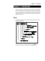
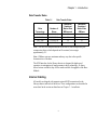
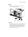
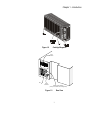
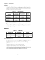
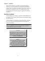
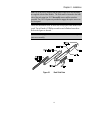


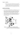


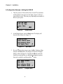

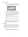
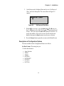


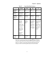

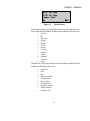

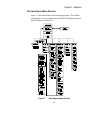


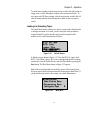
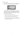

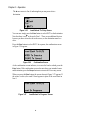
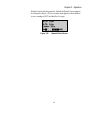


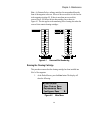
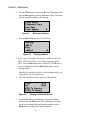


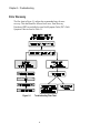
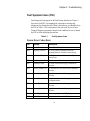
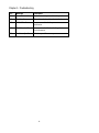
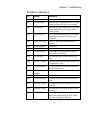
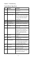
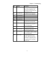
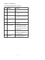
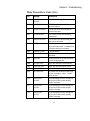
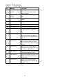

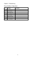

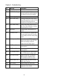
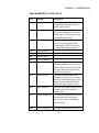
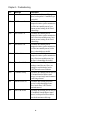
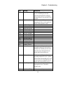
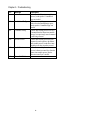

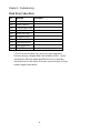


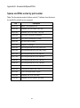
![[ 富士ドライケム IMMUNO AG カートリッジ StrepA ] ≫PDF](http://vs1.manualzilla.com/store/data/006615284_2-99f2f98b9ada0eb24857a64ca08ee58e-150x150.png)