1
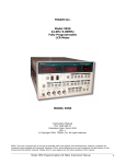
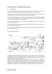
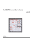
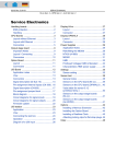
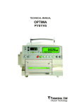
Emergency Warmer
ESH 04
Service Manual
Table of Contents
1.
2.
3.
4.
5.
6.
7.
8.
9.
Technical Information
Safety Information / Warranty
Alarms / Safety Shut Off
Circuit Schematics and Layouts
Block Diagram
Parts Lists
Test Sheet and Test Log Procedure
Safety Checks
Spare Parts
July 2004
ESH 04 – Service Documentation
3
4
5,6
7-12
13
14-18
19-24
25
26
Page 2
1. Technical Information
Technical Information
ESH 04:
Type designation
Rated voltage
Line frequency
Power consumption
Operating temperature
Emergency shut off
Moisture protection
Protection against electrical shock
Degree of protection against
electrical shock
Dimensions
Weight
Class
Operating mode
July 2004
ESH 04
12 VDC; 100V-240VAC (power supply)
50 / 60 Hz (power supply)
max. 20W
37 °C
double
IPX 4 (splash protection)
built-in rechargeable battery pack
B
W x D x H 190 x 120 x 320 mm
1.3 kg
IIa as defined in Rule 9
continuous
ESH 04 – Service Documentation
Page 3
2. Safety Information / Warranty
•
•
•
•
•
•
•
•
•
•
•
•
•
The Emergency Warmer may only be used or connected in vehicles if the on-board
equipment meets applicable standards and regulations.
The Emergency Warmer must always be hanging when it is in use. It may not be used for
pressure infusion while it is lying on its side or while it is in an inverted upright position.
Otherwise there is a risk that air bubbles may form.
The doctor who is performing treatment must check the patient’s condition at regular
intervals. Failure to do so could pose a serious risk to the patient’s health.
If the device is attached to an infusion pole or stand, the pole or stand must have sufficient
stability and load bearing capacity to support the device.
Force must not be applied to the device or its accessories.
The only way to ensure that the device is disconnected from the line voltage is to unplug the
power adapter.
The system may only be used in conjunction with electrical systems which comply with
applicable standards and regulations.
The device must not be used in potentially explosive atmospheres.
Only persons or service centers that have been authorized by Biegler may carry out repairs or
modifications to the Emergency Warmer.
Fluid, steam or thermochemical methods must not be used to sterilize the device.
The effects of external fields such as electromagnetic radiation and high temperature must be
minimized.
Periodic safety checks must be conducted as defined in the “Periodic Checks” section of the
Operating Manual.
If the device falls, is damaged or does not function as described in the Operating Manual, it
must be shut off immediately and sent for service.
WARRANTY:
Biegler Medizinelektronik provides a device warranty for a period of one year following the date
of sale. The warranty covers defects in materials or workmanship and includes both parts and
labor. The guarantee is valid only if an invoice or receipt is supplied and if the warranty claim is
made within the warranty period. The warranty is void if the device is damaged or is not used or
maintained properly as described in the Operating Manual or if unauthorized work has been
carried out.
July 2004
ESH 04 – Service Documentation
Page 4
3. Alarms / Safety Shut Off
The Emergency Warmer has separate “Self Test” and “Over Temperature Alarm” functions.
SELF TEST:
The software performs periodic self tests. If a fault is detected during one of these tests, the unit
shuts off automatically.
OVER TEMPERATURE ALARM:
As the first level of over temperature protection, the software generates an alarm when the
temperature rises above 41°C, and all functions are shut off. The red Alarm LED is illuminated
and an alarm buzzer sounds to alert the user.
The second-level safety shut off is triggered by the hardware when the temperature exceeds
45°C.
SAFETY SHUT OFF:
The temperature on the ESH 04 is factory set to 37°C. A digital sensor is used to monitor the
temperature. This sensor together with the second-level safety shut off mechanism is mounted on
a small PCB which is attached to the heating mat.
A microcontroller on the ESH 04 provides temperature control, scans the keys, acts as the service
interface and runs the output stage self test. Two power MOSFETs connected in series control
the heating. The controller tests the function of the output transistors every 1,000 milliseconds. If
a fault is detected during this test, the ESH 04 shuts off and generates a visual and acoustic alarm.
July 2004
ESH 04 – Service Documentation
Page 5
If the controller develops a fault, a hardware-based safety shut off overrides the first-level safety
shut off. The second-level over temperature shut off is activated at a fixed temperature of 45°C.
Battery
Temperature
Sensor 1
Voltage monitor
Heater
Sensor 2
T1
The shut off test is
performed every 1000ms
during operation
µP
T2
Temperatur monitor
>50°C
July 2004
ESH 04 – Service Documentation
Page 6
4 . C i r c u i t S c h e m a t i c s a n d L a yo u t s
July 2004
ESH 04 – Service Documentation
Page 7
July 2004
ESH 04 – Service Documentation
Page 8
RED
GREEN
YELLOW
ACT
ON
OFF
July 2004
ESH 04 – Service Documentation
Page 9
July 2004
ESH 04 – Service Documentation
Page 10
July 2004
ESH 04 – Service Documentation
Page 11
Sensor PCB :
July 2004
Component Layout
ESH 04 – Service Documentation
Page 12
5. Block Diagram
July 2004
ESH 04 – Service Documentation
Page 13
6. Parts Lists
NAME
R1
R2
R3
R4
R5
R6
R7
R8
R9
R10
R11
R12
R13
R14
R15
R16
R17
R18
R19
R20
R21
R22
R23
R24
R25
R26
R27
R28
R29
R30
R31
R32
R33
R34
R44-47
July 2004
DESCRIPTION
Res. 100k , SMD 0603
Res. 100k , SMD 0603
Res. 1k , SMD 0603
Res. 1k , SMD 0603
Res. 10k , SMD 0603
Res. 390E , SMD 0603
Res. 390E , SMD 0603
Res. 390E , SMD 0603
Res. 2k2 , SMD 0603
Res. 10k , SMD 0603
Res. 100k , SMD 0603
Res. 270E , SMD 0603
Res. 10k , SMD 0603
Res. 10k , SMD 0603
Res. 0.56E , thru-hole, 0.33W
Res. 0.56E (not populated)
Res. 330k , SMD 0603
Res. 33k , SMD 0603
Res. 470k , SMD 0603
Res. 3k9 , SMD 0603
Res. 10k , SMD 0603
Res. 4k7 , SMD 0603
Res. 100k , SMD 0603
Res. 1M , SMD 0603
Res. 15k , SMD 0603
Res. 100k , SMD 0603
Res. 100k , SMD 0603
Res. 33k , SMD 0603
Res. 1E , thru-hole, 0.33W
Res. 10k , SMD 0603
Res. 2k2k , SMD 0603
Res. 100k , SMD 0603
Res. 100k , SMD 0603 (not
populated)
Res. 0.56 , RL73-3A (not
populated)
Res. 47E, SMD 0207/12 (not
populated)
PART NUMBER
ESH 04 – Service Documentation
ITEM
Page 14
NAME
C1
C2
C3
C4
C5
C6
C7
C8
C9
C10
C11
C12
C13
C14
C15
C16
C17
C18
C19
C20
C21
JP5
JP6
Q1
A1
SU1
ST1
ST2
ST3
ST4
ST5
ST6
July 2004
DESCRIPTION
PART NUMBER
Cap. 10pF , SMD 0603
Cap. 10pF , SMD 0603
Cap. 100nF , SMD 0603
Cap. 10µF , SMD 1210
Cap. 22µF / 16V , SMD 1812
Cap. 100nF , SMD 0603
Cap. 100nF , SMD 0603
Cap. 100nF , SMD 0603
Cap. 100nF , SMD 0603
Cap. 4.7µF / 50V , SMD 1210
Cap. 100nF , SMD 0603
Cap. 22µF / 16V , SMD 1812
Cap. 100nF , SMD 0603
Cap. 100nF , SMD 0603
Cap. 1µF , SMD 0603
Cap. 100nF , SMD 0603
Cap. 100nF , SMD 0603
Cap. 100nF , SMD 0603
Cap. 1µF , SMD 1210
Cap. 1µF , SMD 0603
Cap. 1µF , SMD 0603
PINHD-1X2
PINHD-1X2
Quartz, 16MHz, RM5, Crystal
HC49U70
LION rechargeable battery, 10.8V,
2.3Ah
Buzzer, thru-hole TMB 05
Connector, 1x2 PANCON
Connector. 1x3 PANCON
Connector. 1x3 PANCON
Connector. PF-50x6
Connector. 1x2 PANCON
Connector. Pinhead 2x5 N
ESH 04 – Service Documentation
ITEM
Page 15
NAME
D1
D2
D3
D4
D5
D6
D7
D8
D9
D10
D11
D12
D13
D14
IC1
IC2
IC3
IC4
VA1
VA2
VA3
VA4
VA5
VA6
VA7
VA8
VA9
SI1, SI2
TA1-TA3
JP1-JP4
JP5
HA1-HA3
July 2004
DESCRIPTION
Duodiode BAV 70 , SMD-SOT23
Diode 1N4148 , SMD SOD80
Duodiode BAV 70 , SMD-SOT23
Diode 1N4148 , SMD SOD80
Diode MBRA 140 T3
Diode 1N4148 , SMD SOD80
LED Diode red, 3mm
LED Diode yellow, 3mm
LED Diode green, 3mm
Zener diode, 4V7, SMD
Duodiode BAV 70 , SMD-SOT23
Schottky diode, 3A / 0.45V ,
RB 051L-40, SMD-SMB
Schottky-Diode, 3A / 0.45V ,
RB 051L-40, SMD-SMB
Diode 1N4148 , SMD SOD80
ST 72324
MAX 1615
TC 4SU69F (C-MOS inverter)
LT1513 (D Pack) charging IC
Varistor 18V DC, thru-hole RM5
Varistor 5V, SMD 0603
Varistor 14V, SMD 0603
Varistor 5V, SMD 0603
Varistor 5V, SMD 0603
Varistor 5V, SMD 0603
Varistor 5V, SMD 0603
Varistor 5V, SMD 0603
Varistor 14V, SMD 0603
Fuse 2.5AT, SMD
Pushbutton RAFI 3, AC402
plunger l=7mm, D=8mm
90° base
Jumper
PINHD-1x2
Led holder ELB-LR31R
PART NUMBER
ESH 04 – Service Documentation
ITEM
Page 16
NAME
T1
T2
T3
T4
T5
T6
T7
T8
T9
T10
T11
T12
TH1
L1
L2
L3
L4
L5
L6
L7
L8
L9
L10
L11
L12
L13
Rx
Lx
Cx
Dx
Dy
Dz
July 2004
DESCRIPTION
IPS 021L , BSP75 , SMD SOT223
IPS 021L , BSP75 , SMD SOT223
FET-N-2N7002 , SMD SOT23
FET-N-2N7002 , SMD SOT23
BSS 84 , SMD SOT23
FET-N-2N7002 , SMD SOT23
FET-N-2N7002 , SMD SOT23
FET-N-2N7002 , SMD SOT23
2SJ182 (P-channel FET)
IPS 021L, BSP75, SOT223, (not
populated)
FET-N-2N7002 , SMD SOT23
FET-N-2N7002 , SMD SOT23
Bridge PTC 995, (not populated)
15µH , choke RM3D7
15µH , choke RM3D7
10µH , choke RM5 , WE-PD4
10µH , choke RM5 , WE-PD4
15µH , choke RM3D7
15µH , choke RM3D7
1.5µH , choke, 1206
1.5µH , choke, 1206
1.5µH , choke, 1206
1.5µH , choke, 1206
choke CTX (not populated)
inductor 0.4µH, SM-NE45 (not
populated)
inductor 0.4µH, SM-NE45 (not
populated)
res. 1k , 0.33W, thru-hole
1µH ferrite core,D12, d5, L9 mm
Cap. 1µF , SMD 0603
Diode 1N4148 , SMD SOD80
Diode 1N4148 , SMD SOD80
Diode 1N4148 , SMD SOD80
PART NUMBER
ESH 04 – Service Documentation
ITEM
Page 17
Sensor PCB
NAME
ST1
R1
R5
V1
V2
V3
C3
C4
IC1
IC2
July 2004
DESCRIPTION
4-pole connector, STE4x1-27
Res. 4k7 , SMD-0603
Res. 27k , SMD-0603
Varistor 5V , SMD-0603
Varistor 5V , SMD-0603
Varistor 5V , SMD-0603
Cap. 100nF / 25V , SMD-0603
Cap. 100nF / 25V , SMD-0603
Thermostat AD22105 , SO 08
Temperature sensor DS18B20
SO 08
PCB NOTF_1_2
PART NUMBER
ESH 04 – Service Documentation
ITEM
Page 18
7. Test Sheet and Test Log Procedure
Test Sheet Procedure
ESH 04
Emergency Warmer
July 2004
ESH 04 – Service Documentation
Page 19
ESH 04 Test
Persons performing this procedure must have a very good understanding of
the various test steps.
The procedure should be used as a reference in conjunction with the ESH
04 test sheet. If applicable, BIEGLER will provide updates as supplemental
sheets, which must be immediately inserted into the procedure.
Test sequence :
Start the communications program at the computer.
Connect the communications cable to the ESH04.
Connect the ESH04 to the power adapter.
Use a stop watch to check the whether the time counts down from 255 at
one minute intervals. (Observe for at least two minutes.)
Monitor display: S (Standby), N (power), 0 (no heating).
Check the charge function on the ESH04 – the Charge LED must be
illuminated.
Check charge shut off: press the “L” key on the computer
(simulates one minute charging time).
The Charge LED on the ESH04 must turn off after one minute.
Turn on theESH04.
Check whether the “On” LED is illuminated and the ESH04 is heating.
Monitor display: B (operating), N (power), 1 (heating).
Unplug the power adapter and plug it in again (check the Charge LED).
Shut off the ESH04, disconnect the power adapter and connect it again.
(Timer set).
Charging starts; it should be finished after 4:15 hrs.
(Charge LED must not be illuminated).
July 2004
ESH 04 – Service Documentation
Page 20
Temperature test:
Place 2 infusion flasks (500 ml) into the ESH04. Attach a temperature
probe half way up the left flask along side of the right flask. The
temperature meter should have an accuracy of 0.1°C.
Take the measurement at room temperature (flasks and device) with the
communications cable attached and without the power adapter.
Pump the pressure bag up to 300mmHg.
Turn on the ESH04. The unit should still be heating after about 90 minutes
(the rechargeable battery is then OK).
Connect the device to the power adapter and after another 30 minutes
check the regulated temperature (37 +/- 1.5°C). Watch the temperature
control (0 and 1 on the monitor).
Check to ensure that the pressure cuffs for leaks.
When the temperature test has run for more than 120 minutes, a minimum
pressure of 200mmHg should still be present.
Continuous test :
• Startup at room temperature with two 500ml flasks.
• After about 2 hours, measure the temperature at the flask.
• After 24h, measure the temperature again at the flask.
The initial and final values must remain within the tolerances. Be sure that
ambient conditions are always the same when you take the measurements.
The final value may deviate by ± 0.5°C from the initial value.
DETAIL VIEWS:
July 2004
ESH 04 – Service Documentation
Page 21
Complete
pressure cuff
+ heating foil:
ESH04 populated PCB with
battery and lower housing:
Complete housing with cable connection
(serial communications connector)
July 2004
ESH 04 – Service Documentation
Page 22
Emergency Warmer ESH04 Test Log
____________________________________________________
INITIAL TEST / MAINTENANCE TEST
Device No.: ...............................
Date: ......../......../..............
A detailed knowledge of the applicable procedure is required to perform
these tests.
TEST
NOMINAL / FUNCTION
RESULT
OK
1.Data communications
PC communications
2.Check charge cycle
shut off ( “L” )
3.Operating temp.
simulated charging time 1 min. Charge LED turns off
37°C +/- 1.5°C (after about 2 hrs.)
not OK
Battery operation - power
adapter
4.Pressure sleeve
leakage
initial : min. 300 mmHg
final : min. 200 mmHg
5. Battery charging
about 4.5 hr.
Charge LED turns off
6.Elect. safety
see printout
7.Mech. condition
8.Contamination
9.Markings
10. Visual inspection
device / power adapter
Signature of test
engineer:
July 2004
ESH 04 – Service Documentation
Page 23
8. Safety Checks
Periodic checks must be carried out on the ESH 04 Emergency Warmer at least
every 12 months. Persons performing the checks must have sufficient training,
knowledge and practical experience to conduct safety checks.
• The safety information on the unit and its accessories must be clearly legible.
• The mechanical condition of all components must be suitable for continued safe
use (housing, zipper, cord, window, stitching, cable, tubing, manometer and
hand pump).
• There must be no contamination on the Emergency Warmer which could impair
safety.
• Electrical testing of the power adapter (equivalent device leakage current, power
consumption)
July 2004
ESH 04 – Service Documentation
Page 24
Page 1
EMERG WARMER ESH04 Test Procedure
---------------------------------------------------------------------------
Electrical Safety
Item
Description
--------------------------------------------------------------------------GERB023 Calibrate test lead
Measure resistance to the protective conductor
Units: Ohms
Units: Ohms
spec. value: 0.00
spec. value: 0.00
limit: 0.00
limit: 0.00
abs.tol.: 0.00
abs.tol. :0.00
rel.tol.: 0.00
rel.tol.: 0.00
limit: 0.00
limit: 0.00
abs. tol.: 0.00
abs. tol.: 0.00
rel. tol. 0.00
rel. tol. 0.00
GERB001 Line voltage test
Measure the line voltage (RMS)
Units: VOLTS spec. value: 230
Units: VOLT
spec. value: 230
GERB024 Power consumption test
Measure the RMS power consumption of the device under test.
The test has a time limit. A message is issued if the time is exceeded.
Maximum power 3.5 kVA.
Be sure that the blood heater is in the heating phase when you take this measurement.
.
Units: Watts
Units: Watts
spec. value: 0.00
spec. value: 0.00
limit: 0.00
limit: 0.00
abs. tol.: 0.00
abs. tol.: 0.00
rel. tol. 0.00
rel. tol. 0.00
GERB019 Derived leakage current as show in Fig.9 and defined in VDE 0751
The line voltage is the test voltage which is applied to the device under test.
Measure the current which flows from the housing to ground.
The derived leakage current must not be more that 1.5 times the initial value and it also must
not exceed the limit value of 750 µA.
Line power switch: ON.
Units: µA
Units: µA
July 2004
spec. value: 0.00
spec. value: 0.00
limit: < 750
limit: < 750
abs. tol.: 0.00
abs. tol.: 0.00
ESH 04 – Service Documentation
rel. tol.: 0.00
rel. tol.: 0.00
Page 25
PARTS LIST
9. Spare Parts
DESCRIPTION
Charger complete
Vehicle charger cable
ESH04 cable
Pressure cuffs + heating foil complete
Populated ESH04 PCB
Rechargeable battery pack (lithium ion)
Rubber bellows with discharge screw
Manometer with side connection ( 0 – 300 mmHg )
Pressure bag
Case
July 2004
ESH 04 – Service Documentation
PART NO.
FL 1000001
FL 1000002
FL 1000003
LE 1000001
IP 9004026
IE 2001006
DA 1006004
DC 1040003
DS 4230221
JR 1005001
Page 26