1
OPERATOR'S MANUAL
FACSIMILE RECEIVER
Model
FAX-30
www.furuno.com
(Elemental Chlorine Free)
The paper used in this manual
is elemental chlorine free.
FURUNO Authorized Distributor/Dealer
9-52, Ashihara-cho,
Nishinomiya, 662-8580, JAPAN
All rights reserved.
Printed in Japan
A: SEP. 2002
H: JUL. 25, 2013
Pub. No. OME-62600-H
(AKMU) FAX-30
00080937514
IMPORTANT NOTICES
General
• This manual has been authored with simplified grammar, to meet the needs of
international users.
• The operator of this equipment must read and follow the descriptions in this manual.
Wrong operation or maintenance can cancel the warranty or cause injury.
• Do not copy any part of this manual without written permission from FURUNO.
• If this manual is lost or worn, contact your dealer about replacement.
• The contents of this manual and equipment specifications can change without notice.
• The example screens (or illustrations) shown in this manual can be different from the
screens you see on your display. The screens you see depend on your system
configuration and equipment settings.
• Save this manual for future reference.
• Any modification of the equipment (including software) by persons not authorized by
FURUNO will cancel the warranty.
• All brand and product names are trademarks, registered trademarks or service marks of
their respective holders.
• Windows Vista, Internet Explorer and Windows are either registered trademarks or
trademarks of Microsoft Corporation in the United States and/or other countries.
How to discard this product
Discard this product according to local regulations for the disposal of industrial waste. For
disposal in the USA, see the homepage of the Electronics Industries Alliance
(http://www.eiae.org/) for the correct method of disposal.
How to discard a used battery
Some FURUNO products have a battery(ies). To see if your product has a battery, see the
chapter on Maintenance. Follow the instructions below if a battery is used. Tape the + and terminals of battery before disposal to prevent fire, heat generation caused by short circuit.
In the European Union
The crossed-out trash can symbol indicates that all types of
batteries must not be discarded in standard trash, or at a trash
site. Take the used batteries to a battery collection site
according to your national legislation and the Batteries Directive
Cd
2006/66/EU.
In the USA
The Mobius loop symbol (three chasing arrows) indicates that
Ni-Cd and lead-acid rechargeable batteries must be recycled.
Take the used batteries to a battery collection site according to
local laws.
Ni-Cd
Pb
In the other countries
There are no international standards for the battery recycle symbol. The number of symbols
can increase when the other countries make their own recycling symbols in the future.
i
SAFETY INSTRUCTIONS
Safety Instructions for the Operator
WARNING
ELECTRICAL SHOCK HAZARD
CAUTION
Use the proper fuse.
Do not open the equipment.
Only qualified personnel
should work inside the
equipment.
Immediately turn off the power at the
switchboard if water leaks into the
equipment or something is dropped in
the equipment.
Continued use of the equipment can cause
fire or electrical shock. Contact a FURUNO
agent for service.
Do not disassemble or modify the
equipment.
Fire, electrical shock or serious injury can
result.
Do not place liquid-filled containers on
the top of the equipment.
Fire or electrical shock can result if a liquid
spills into the equipment.
Immediately turn off the power at the
switchboard if the equipment is emitting
smoke or fire.
Continued use of the equipment can cause
fire or electrical shock. Contact a FURUNO
agent for service.
Make sure no rain or water splash leaks
into the equipment.
Fire or electrical shock can result if water
leaks in the equipment.
ii
Use of a wrong fuse may cause
serious damage to the equipment
and void the warranty.
WARNING LABEL
A warning label is attached to the
facsimile receiver. Do not remove the
label. If the label is missing or illegible,
contact a FURUNO agent or dealer
about replacement.
WARNING
To avoid electrical shock, do not
remove cover. No user-serviceable
parts inside.
Name: Warning Label (1)
Type: 86-003-1011-1
Code No.: 100-236-231
Safety Instructions for the Installer
CAUTION
WARNING
ELECTRICAL SHOCK HAZARD
Do not open the equipment
unless totally familiar with
electrical circuits and
service manual.
Only qualified personnel
should work inside the
equipment.
Observe the following compass safe
distances to prevent interference to a
magnetic compass:
Standard
compass
Facsimile
Receiver
0.9 m
Steering
compass
0.6 m
Turn off the power at the switchboard
before beginning the installation.
Fire or electrical shock can result if the
power is left on.
Do not install the equipment where it
may get wet from rain or water splash.
Water in the equipment can result in fire,
electrical shock or damage the equipment.
Be sure that the power supply is
compatible with the voltage rating of
the equipment.
Connection of an incorrect power supply
can cause fire or damage the equipment.
iii
TABLE OF CONTENTS
FOREWORD .................................................................................................................vii
SYSTEM CONFIGURATION ...........................................................................................x
EQUIPMENT LISTS ......................................................................................................xii
1. OVERVIEW, SETUP ................................................................................................ 1-1
1.1 Setup: NavNet and NavNet vx2 .............................................................................................. 1-1
1.1.1 Controls ......................................................................................................................... 1-1
1.1.2 Preparations for using the FAX-30................................................................................ 1-2
1.1.3 Accessing the FAX mode .............................................................................................. 1-3
1.1.4 Choosing the receive mode .......................................................................................... 1-4
1.1.5 Receive notification ....................................................................................................... 1-5
1.2 Setup: PC ................................................................................................................................ 1-6
1.2.1 Accessing the FAX-30 top display ................................................................................ 1-6
1.2.2 Choosing the receive mode .......................................................................................... 1-8
1.2.3 Logging out.................................................................................................................... 1-8
1.3 Setup: NavNet 3D.................................................................................................................... 1-9
1.3.1 Controls ......................................................................................................................... 1-9
1.3.2 How to use FAX-30 with NavNet 3D ........................................................................... 1-10
1.3.3 Receive mode ............................................................................................................. 1-12
1.3.4 Logout.......................................................................................................................... 1-12
2. FAX OPERATION: NavNet and NavNet vx2 .......................................................... 2-1
2.1 Automatic Receiving................................................................................................................ 2-1
2.1.1 Choosing channel.......................................................................................................... 2-1
2.1.2 Previewing image being received ................................................................................. 2-4
2.1.3 Stopping automatic receiving ........................................................................................ 2-4
2.2 Manually Starting, Stopping Receiving.................................................................................... 2-5
2.2.1 Manually starting receiving............................................................................................ 2-5
2.2.2 Manually stopping receiving.......................................................................................... 2-6
2.3 Timer Receiving....................................................................................................................... 2-7
2.3.1 Setting timer receiving schedule ................................................................................... 2-7
2.3.2 Turning on/off specific timer programs.........................................................................2-11
2.3.3 Clearing all timer programs ..........................................................................................2-11
2.4 Displaying Facsimile Images................................................................................................. 2-12
2.5 Processing Facsimile Images................................................................................................ 2-13
2.5.1 Phase mismatch.......................................................................................................... 2-13
2.5.2 Phasing signal out of synchronization ........................................................................ 2-13
2.5.3 Noise rejection............................................................................................................. 2-14
2.5.4 Image color.................................................................................................................. 2-15
2.5.5 Image format ............................................................................................................... 2-15
2.5.6 Zooming images.......................................................................................................... 2-16
2.5.7 Rotating images .......................................................................................................... 2-16
2.6 Erasing Facsimile Images ..................................................................................................... 2-16
2.7 Preventing Erasure of Facsimile Images .............................................................................. 2-17
2.8 Adding Facsimile Channels................................................................................................... 2-18
iv
3. FAX OPERATION: NavNet 3D, PC ..........................................................................3-1
3.1 Automatic Receiving................................................................................................................ 3-1
3.1.1 Starting receiving........................................................................................................... 3-1
3.1.2 Stopping receiving......................................................................................................... 3-1
3.2 Timer Receiving....................................................................................................................... 3-2
3.2.1 Setting, changing timer receiving schedule .................................................................. 3-2
3.2.3 Turning on/off specific timer programs.......................................................................... 3-4
3.2.4 Clearing all timer programs ........................................................................................... 3-4
3.3 Displaying Facsimile Images................................................................................................... 3-5
3.4 Processing Facsimile Images.................................................................................................. 3-6
3.4.1 Phase mismatch............................................................................................................ 3-6
3.4.2 Phasing signal out of synchronization........................................................................... 3-7
3.4.3 Noise rejection............................................................................................................... 3-7
3.4.4 Image color.................................................................................................................... 3-8
3.4.5 Image format ................................................................................................................. 3-8
3.4.6 Rotating images ............................................................................................................ 3-9
3.4.7 Zooming images............................................................................................................ 3-9
3.4.8 Saving images............................................................................................................... 3-9
3.5 Erasing Facsimile Images ....................................................................................................... 3-9
3.6 Preventing Erasure of Facsimile Images .............................................................................. 3-10
3.7 Adding Facsimile Channels ....................................................................................................3-11
4. NAVTEX OPERATION: NavNet and NavNet vx2 ...................................................4-1
4.1 About Navtex Messages.......................................................................................................... 4-1
4.1.1 Message categories ...................................................................................................... 4-1
4.1.2 Receiving navtex messages ......................................................................................... 4-1
4.2 Setting Up Navtex Stations, Messages, Alarms ..................................................................... 4-2
4.3 Previewing Incoming Navtex Messages ................................................................................. 4-5
4.4 Displaying Navtex Messages .................................................................................................. 4-6
4.4.1 Displaying navtex messages......................................................................................... 4-6
4.4.2 Remarks on navtex messages...................................................................................... 4-7
4.5 Displaying the Navtex Station List ........................................................................................... 4-8
4.6 Adding Navtex Stations ........................................................................................................... 4-9
5. NAVTEX OPERATION: NavNet 3D, PC...................................................................5-1
5.1 About Navtex Messages.......................................................................................................... 5-1
5.1.1 Message categories ...................................................................................................... 5-1
5.1.2 Receiving navtex messages ......................................................................................... 5-1
5.2 Setting Up Navtex Stations, Messages................................................................................... 5-2
5.3 Displaying Navtex Messages .................................................................................................. 5-3
5.4 Displaying the Navtex Station List ........................................................................................... 5-4
5.5 Adding Navtex Stations ........................................................................................................... 5-5
5.6 Editing Navtex Stations............................................................................................................ 5-6
5.7 Deleting Navtex Stations ......................................................................................................... 5-7
6. MAINTENANCE, TROUBLESHOOTING .................................................................6-1
6.1 Maintenance ............................................................................................................................ 6-1
6.2 Replacement of Fuse .............................................................................................................. 6-2
6.3 Troubleshooting ....................................................................................................................... 6-2
v
6.4 Diagnostics .............................................................................................................................. 6-3
6.4.1 NavNet........................................................................................................................... 6-3
6.4.2 NavNet 3D, PC.............................................................................................................. 6-4
6.5 Clearing Data........................................................................................................................... 6-5
6.5.1 NavNet........................................................................................................................... 6-5
6.5.2 NavNet 3D, PC.............................................................................................................. 6-6
6.6 All Clear (for technicians) ........................................................................................................ 6-7
6.7 Simulation Mode...................................................................................................................... 6-8
6.7.1 NavNet........................................................................................................................... 6-8
6.7.2 Navnet 3D, PC .............................................................................................................. 6-9
7. INSTALLATION........................................................................................................ 7-1
7.1 Facsimile Receiver .................................................................................................................. 7-1
7.2 Antenna Unit............................................................................................................................ 7-2
7.2.1 General antenna connection......................................................................................... 7-2
7.2.2 Wire antenna or whip antenna ...................................................................................... 7-2
7.2.3 Installation of preamp unit FAX-5 (option) .................................................................... 7-3
7.3 Wiring....................................................................................................................................... 7-4
7.4 Supplying Power to the Preamp Unit ...................................................................................... 7-6
7.5 Browser, PC Settings............................................................................................................... 7-7
7.5.1 Browser settings............................................................................................................ 7-7
7.5.2 PC settings .................................................................................................................... 7-8
APPENDIX ............................................................................................................... AP-1
Facsimile Stations........................................................................................................................ AP-1
Navtex Stations............................................................................................................................ AP-4
Menu Tree ................................................................................................................................... AP-9
SPECIFICATIONS .....................................................................................................SP-1
PACKING LIST............................................................................................................ A-1
OUTLINE DRAWINGS ................................................................................................D-1
INTERCONNECTION DIAGRAM ................................................................................ S-1
INDEX.........................................................................................................................IN-1
vi
FOREWORD
A Word to the Owner of the FAX-30
FURUNO Electric Company thanks you for purchasing the FURUNO FAX-30 Facsimile
Receiver. We are confident you will discover why the FURUNO name has become
synonymous with quality and reliability.
Since 1948, FURUNO Electric Company has enjoyed an enviable reputation for quality and
reliability throughout the world. This dedication to excellence is furthered by our extensive
global network of agents and dealers.
Your equipment is designed and constructed to meet the rigorous demands of the marine
environment. However, no machine can perform its intended function unless properly
installed and maintained. Please carefully read and follow the operation, installation and
maintenance procedures set forth in this manual.
We would appreciate feedback from you, the end-user, about whether we are achieving our
purposes.
Thank you for considering and purchasing FURUNO.
Features
Connected to a NavNet series display unit (MODEL 1833C/1943C, MFDBB, MFD8/MFD12)
or a PC, the FAX-30 receives facsimile images and navtex messages, transmitted from
facsimile and navtex stations.
• Programmed with all existing facsimile stations and frequencies. User may program 320
channels.
• Fully automatic facsimile operation with built-in schedule timer. Storage for 30 timer
programs.
• Fully automatic selection of speed, IOC, phase alignment and frequency. Manual
selection also available.
• Connection to printer via a PC to print facsimile images and navtex messages.
• Facsimile images in monochrome, gray scale (8 tones) or color (three patterns).
• Built in navtex receiver. (The receiver does not conform to GMDSS regulations.)
vii
Operational Characteristics
General
• The equipment receives one facsimile image or naxtex message at a time. Thus, a
navtex message cannot be received when a facsimile image is being received and vice
versa, regardless of navtex message category.
• Three receiving modes are available, facsimile, navtex, and facsimile(timer) & navtex.
When using the facsimile(timer) and navtex, the order of priority is
Facsimile(timer) (highest priority) → Navtex (lowest priority)
• The FAX-30 does not have an internal clock, so time is input from a NavNet display or the
PC. (For a PC-only configuration, time data is read when the browser accesses the
FAX-30. Therefore, turn on the FAX-30 before accessing it from the PC to allow for input
of time data, which is necessary for facsimile timer recording.) To receive time data, do
the following:
NavNet: Output the date and time data sentence ZDA through the NavNet network.
PC: Set the PC’s clock to the correct time.
• If both a NavNet series unit and a PC are used, it is recommended to operate the FAX-30
from the PC because of the two different communication protocols. (Use the NavNet
series unit to feed navigation data to the PC.)
• Navigation data must be fed through the network to use the automatic navtex mode.
Therefore, this mode is not available in the PC-only configuration.
NavNet
• The FAX-30 cannot be accessed from the NavNet for 15 seconds after the FAX-30 has
been turned on.
• NavNet requirements:
Navionics: Ver. 15, Boot Ver. 2 (1950006002)
C-MAP by Jeppesen: Ver. 11, Boot Ver. 2 (1950006002)
NavNet 3D
The FAX-30 cannot be accessed when it is starting up, because image data is being loaded.
You can access the FAX-30 when the LED flashes 0.4 seconds every 2 seconds, which
starts approximately two minutes after the power is turned on.
PC
• The FAX-30 cannot be accessed from the PC while the FAX-30 is loading data at start up.
Wait until the POWER LED flashing interval changes from 0.4 to two seconds before
accessing the FAX-30.
• Most operating procedures in this manual are written for use with the Internet Explorer®.
Menu items, control button names, etc. may be different on the Netscape Navigator.
viii
• PC requirements:
OS:
Windows® 98, Windows® 2000, Windows® XP, Windows Vista®,
Windows® 7(32bit/64bit)
Memory:
Min.128 MB
CPU:
Min. 600 MHz
Resolution: 1024x768 pixels
• Browser requirements:
Internet Explorer®: Ver.5.01/5.5/6.0/7.0/8.0
Netscape Navigator: Ver.4.78/6.2/7.0
• OS and browser compatibility
Internet Explorer®
Netscape Navigator
Ver. 5.01
SP2
Ver. 5.5
SP2
Ver 6.0
SP1
Ver
7.0
SP0
Ver
8.0
SP0
Ver.
4.78
Ver.
6.2
Ver.
7.0
Windows® 98
OK
OK
#
#
#
*1, *2
*2
NO, *3
Windows® 2000
OK
OK
OK
#
#
*1
#
OK
Windows® XP
#
#
OK
#
#
#
#
OK
Windows Vista®
#
#
#
OK
#
#
#
#
Windows® 7
#
#
#
#
OK
#
#
#
*1 A facsimile image may not be updated after it has been processed (noise limiter,
zoom, etc.). To update the image, click the right button on the mouse while holding
down the [SHIFT] key and then choose Reload.
*2 Connection is occasionally interrupted. In case of 4.78 + Win 98, the message “A
network error occurred: unable to connect to server (TCP Error: Not enough
memory). The server may be down or unreachable. Try connecting again later.” is
displayed. To restore the connection, press [Ctrl]+[Alt]+[Delete] to force quit Netscape.
Then, reopen Netscape and try to connect again.
*3 Connection is frequently interrupted and cannot be restored.
#
Not verified.
• Use of older OS with recent browser will result in extremely slow operation.
• If the browser goes into timeout while an image is being received, access to the FAX-30
may be interrupted. In this case, click the right button on the mouse and click Refresh.
• Most PC operations are done with the left button on the mouse. The exception is saving a
facsimile image that is done with the right button.
• The FAX-30 cannot be simultaneously accessed by multiple PCs. For this reason, be
sure to use the logout feature to logout a PC from the FAX-30 when its use is not
required.
• If the FAX-30 appears to be abnormal, the browser version may not be compatible or
browser settings may be wrong. See the browser requirements on the previous page, the
browser and OS compatibility table above and the browser settings in paragraph 7.5.1.
• The HTTP and HTML versions of the FAX-30 are as shown below.
HTTP: Ver. 1.0
HTML: Ver. 4.01
ix
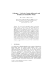
SYSTEM CONFIGURATION
Installation with NavNet, NavNet vx2, NavNet 3D
PREAMP
FAX-5
Wire
Antenna
FACSCIMILE RECEIVER
FAX-30
HUB*
NavNet,
NavNet vx2
or
NavNet 3D
Ship's Mains
12-24 VDC
: Standard
: Option
: User Supply
x
* = HUB is not required to connect
NavNet/NavNet vx/NavNet 3D
directly to FAX-30.
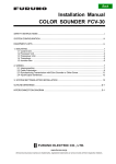
PC installation
PREAMP
FAX-5
Wire
Antenna
FACSIMILE
RECEIVER
FAX-30
HUB*
PC
Printer
PC
: Standard
: Option
: Local Supply
Ship’s Mains
12-24 VDC
FAX-30 cannot be
accessed by more
than one PC at a time.
* = HUB is not required to connect single PC.
xi
EQUIPMENT LISTS
Standard supply
Name
Facsimile
Receiver
Spare Parts
Installation
Materials
xii
Type
FAX-30-E-AN
FAX-30-E-AP
FAX-30-E-N
SP08-01901
CP08-01700
Code No.
—
—
—
005-952-780
000-057-103
CP08-01710
000-057-104
CP08-01720
000-057-105
Qty
Select
one
1 set
Choose
one
Remarks
With Net cable
With PC cable
No connection cable
Fuse, 2 pcs.
• Power Cable
MJ-A3SPF0024-035C
• Net Cable
MJ-A6SPF0014-050C
• Tapping screw (5x20)
• Power Cable
MJ-A3SPF0024-035C
• PC Cable
MJ-A6SPF0017-050C
• Tapping screw (5x20)
• Power Cable
MJ-A3SPF0024-035C
• Tapping screw (5x20)
Optional supply
Name
Preamp Unit
Preamp Unit
Hose Clamp
Whip Antenna
Extension
Cable Kit
Cable Assy.
FAX-5
FAX-5
OP08-11
04S4176
OP-04-2 *10*
OP-04-2 *20*
OP-04-2 *30*
OP-04-2 *40*
OP-04-2 *50*
MJA6SRMD/TM11AP8-005
Code No.
000-075-016
000-075-049
005-946-960
000-153-122
000-041-174
000-041-175
000-041-176
000-041-177
000-041-178
000-144-463
Cable Assy.
MJ-A6SPF0017-050C
000-159-705-11
Coaxial Plug
Adaptor
Adaptor
Cable Assy. MJ
FM-MP-7
MP-M3A
MP-M5A
MJ-A6SPF0014-010C
MJ-A6SPF0014-050C
MJ-A6SPF0014-100C
MJ-A6SPF0014-200C
MJ-A6SPF0014-300C
FAX-30-APT
000-161-293-10
000-161-295-10
000-161-296-10
000-154-027-10
000-154-049-10
000-154-050-10
000-154-051-10
000-154-052-10
005-964-310
Automatic
Printing
Software
Type
Remarks
w/15 m cable
w/1 m cable
For fixing FAX-5 to a mast
2.6 m, for FAX-5
M-connector at both ends
Net conversion cable, for
HUB, NavNet
Net conversion cable, for
HUB, PC
For cable 7C2V, RG8/U, etc.
For cable 3C2V, 3D2V, etc.
For cable 5C2V, 5D2V, etc.
1m
Net cable
5m
10 m
20 m
30 m
xiii
This page intentionally left blank.
xiv
1.
OVERVIEW, SETUP
1.1
Setup: NavNet and NavNet vx2
1.1.1
Controls
Trackball
Chooses menu items and options.
Displays the mode
selection window.
Displays alarm message board.
Clears data.
Opens FAX-30 menu; returns to standby.
Soft keys
ABC
1
DEF
2
GHI
3
JKL
4
MNO
5
PQR
6
STU
7
VWX
8
YZ&
9
EBL
VRM
_'#
0
GAIN
ENTER knob
Push: Registers setting.
Rotate: Selects menu items and options.
May also be used to enter alphanumeric data.
Enter alphanumeric data.
Long press: Turns power off.
Momentary press: Turns the power on;
opens the display for adjustment of brilliance.
Controls
Note 1: For NavNet operating procedures, see the operator’s manual of the
NavNet display unit.
Note 2: The example screens shown in this manual may not match the screens
you see. The screen you see depends on your equipment settings and
system configuration.
1-1
1. OVERVIEW, SETUP
1.1.2
Preparations for using the FAX-30
The NavNet series display unit must output the date and time data sentence
ZDA through the network in order to use the facsimile timer recording feature.
Further, automatic navtex requires the geographical position data sentence GGA
(GPS position fix data) or GLL (geographic position, latitude/longitude). Output
appropriate data sentences from the NavNet display unit to the FAX-30 as
follows:
1. Turn on the NavNet display unit. From the radar, plotter or echo sounder
display, press the [MENU] key.
2. Press the SYSTEM CONFIGURATION soft key.
3. Press the SYSTEM SETUP soft key.
4. Press the PORT SETUP soft key.
5. Press the OUTPUT THROUGH NETWORK soft key.
-ON
----ON
---ON
ON
-ON
--ON
-----
AAM
APB
BOD
BWR*
DPT
GGA
GLL
GTD
MTW
RMA
RMB
RMC
VHW
VTG
WPL
XTE
ZDA
HDT
HDG
MWV
TTM
SELECT
SNTNC
ON/OFF
RETURN
*: BWR: Rhumb line
BWC: Great circle
Select sentence window
6.
7.
8.
9.
1-2
Rotate the [ENTER] knob to choose GGA, GLL or ZDA.
Press the ON/OFF soft key to display ON.
Repeat steps 6 and 7 to set the other two sentences to ON.
Press the [MENU] key to close the menu.
1. OVERVIEW, SETUP
1.1.3
Accessing the FAX mode
1. Turn on the FAX-30 at the ship’s mains switchboard. The FAX-30 proceeds in
the following sequence:
a) The FAX-30 starts initial set up, which takes about 15 seconds.
b) The FAX-30 transfers (loads) data from the ROM to the RAM. At this time the
LED flashes every 0.4 seconds.
c) After all data has been loaded, which takes about two minutes, the LED
flashes every two seconds, indicating the FAX-30 is ready for operation.
LED
(green)
FAX-30, top view
2. Press the [DISP] key to show the display selection window.
Fax mode icon
RADAR
PLOTTER SOUNDER
HOTPAGE 1 HOTPAGE 2 HOTPAGE 3
NAV DATA OVERLAY
HOTPAGE 4
HOTPAGE 5
EXT VIDEO WXFAX
HOTPAGE 6
· TURN KNOB TO SELECT MODE
AND PUSH KNOB TO ENTER.
· PUSH ANY SOFTKEY TO
SELECT IMAGE SOURCE.
Display selection window
3. Rotate the [ENTER] knob to choose the WXFAX icon.
4. Push the [ENTER] knob to show the fax standby display.
Note 1: The FAX-30 cannot be accessed during the 15-second start up period
that occurs after the power has been turned on.
Note 2: If the FAX-30 is not connected to the NavNet display unit when the
display unit is powered, the message “AUX SOURCE IS
DISCONNECTED. PUSH ENT KNOB TO EXIT.” appears. Check
connections between the FAX-30 and the NavNet display unit.
Note 3: “LOAD IMAGES” is displayed while the FAX-30 is loading data.
1-3
1. OVERVIEW, SETUP
The standby display is where you begin all facsimile and navtex operations. If a
facsimile image has been received, the latest facsimile image is displayed.
FAX-30
Facsimile image area
WX FAX
NAVTEX
Soft keys
MODE
SETUP
Standby display
1.1.4
Choosing the receive mode
The FAX-30 has three modes: facsimile only, navtex only, and facsimile (timer) &
navtex. Choose desired mode as follows:
1. At the facsimile standby display, press the MODE SETUP soft key.
(Facsimile image area)
MODE
SETUP
RX
MODE
RX
NOTICE
RETURN
Receive mode setup screen
2. Press the RX MODE soft key.
RX MODE
▲
WX FAX
NAVTEX
FAX (TIMER) & NAV
▼
RX mode options
3. Rotate the [ENTER] knob to choose receive mode desired and press the
ENTER soft key.
1-4
1. OVERVIEW, SETUP
1.1.5
Receive notification
You may wish to be notified after a facsimile image or navtex message arrives.
Notification is done by showing the “fax/navtex received” icon ( ) at the
left-hand side of the screen in display modes other than the fax mode.
A
U
X
1. At the facsimile standby display, press the MODE SETUP soft key.
2. Press the RX NOTICE soft key.
RX NOTICE
▲
ON
OFF
▼
RX notice options
3. Rotate the [ENTER] knob to choose ON or OFF as appropriate.
4. Press the ENTER soft key.
1-5
1. OVERVIEW, SETUP
1.2
Setup: PC
1.2.1
Accessing the FAX-30 top display
1. Turn on the FAX-30 at the breaker on switchboard. The FAX-30 proceeds in
the following sequence:
a) The FAX-30 starts initial set up, which takes about 15 seconds.
b) The FAX-30 transfers (loads) data from the ROM to the RAM. At this time the
LED flashes every 0.4 seconds.
c) After all data has been loaded, which takes about two minutes, the LED
flashes every two seconds, indicating the FAX-30 is ready for operation.
2. Start up the browser software.
3. After the LED on the FAX-30 starts flashing every two seconds, type in the
FAX-30’s URL http://172.31.8.1 and then press the [Enter] key. The facsimile
receiver top display appears. (For one-touch access to the FAX-30 make a
bookmark.)
FACSIMILE RECEIVER
FAX-30
WX FAX
NAVTEX
LOGOUT
Facsimile receiver top display
4. Click WX FAX for facsimile or NAVTEX for navtex to show the corresponding
standby display, which is where you begin all facsimile (or navtex) operations.
1-6
1. OVERVIEW, SETUP
Facsimile image data
(Changes with picture
received.)
100N
3625.kHz
IOCXX10 XXXrpm
SS=XXX SN=XX
STBY
MENU
Click to return to
top display
<< Top
CHANNEL SETUP
Received facsimile
image thumbnails
appear here.
TIMER SETUP
Top menu
EDIT STATION LIST
SYSTEM SETUP
RX MODE
Fax standby display
Navtex mesasge data
(Changes with message
received.)
Navtex message
list appears here.
518kHz
AUTO LAT/LON OK
SS=10
STBY
MENU
Click to return to
top display
Top menu
Navtex message
display area
<< Top
RX SETUP
EDIT STATION LIST
SYSTEM SETUP
RX MODE
Navtex standby display
Standby displays
After you are in a standby display time data is transferred from the PC to the
FAX-30.
Note 1: After turning on the FAX-30 be sure to access it from the PC. Then,
even if the PC is turned off, time data is stored in the FAX-30, for use
with timer recording.
Note 2: The example screens shown in this manual may not match the screens
you see. The screen you see depends on your equipment settings and
system configuration.
1-7
1. OVERVIEW, SETUP
1.2.2
Choosing the receive mode
The FAX-30 has three modes: facsimile only, navtex only, and facsimile (timer) &
navtex. Choose desired mode as follows.
1. At the facsimile or navtex standby display, click RX MODE.
RX MODE
< back
WX FAX
NAVTEX
FAX(TIMER) & NAVTEX
OK
RX mode options
2. Click desired receive mode and then click OK.
3. Click “<back” or Back button to return to the top menu.
1.2.3
Logging out
The FAX-30 cannot be accessed simultaneously by multiple PCs or
NavNet/NavNet 3D units. For this reason, log out a PC or NavNet/NavNet 3D
from the FAX-30 when its use is not required.
1. At the facsimile or navtex menu display, click “<Top” to return to the facsimile
receiver top display. (See the illustration at the top of the previous page.)
2. Click LOGOUT to logout the PC or NavNet/NavNet 3D from FAX-30.
1-8
1. OVERVIEW, SETUP
1.3
Setup: NavNet 3D
1.3.1
Controls
4
3
5
2
1
MFD12 (MFD8 is similar), DCU12
4
1
5
2
3
MCU-001
No.
1
Control
BRILL
(MFD8/12,
DCU12)
(MCU-001)
Description
Momentary push: Turn ON the power; adjust brilliance
(MFD8/12, DCU12).
Long push: Turn OFF the power.
2
DISP
Select a display.
3
CANCEL
Cancel an operation; revert to last-used setting.
CursorPad
Pad: Move Cursor
4
5
: Like Left-button click on PC
MENU
Open and close the menu.
1-9
1. OVERVIEW, SETUP
1.3.2
How to use FAX-30 with NavNet 3D
Connect the FAX-30 to the NavNet 3D. If the IP address of the FAX-30 has been
changed, restore the IP address to [172.31.8.1]. For how to open the installation
wizard, see the installation manual for the NavNet 3D.
1. Turn on the FAX-30 at the switchboard. (The FAX-30 does not have a power
switch.) Check if the power is on or the unit is disconnected, by monitoring
the LED.
a) The initialization of the FAX-30 takes approximately 15 seconds.
b) Data is transferred from the ROM to the RAM. At this time the LED flashes
every 0.4 seconds.
c) It takes about two minutes to send data. The LED blinks every two seconds
when the FAX-30 is available for operation.
2. Push the [DISP] key.
3. Push the RotoKeyTM until the display selection window, shown below,
appears.
Full screen icon
Weather icon
1-10
1. OVERVIEW, SETUP
4. The selector at the left side of the screen is choosing the "full screen" icon.
Push the RotoKeyTM to choose the full screen icon.
5. Rotate the RotoKeyTM to choose the Weather icon at the bottom of the
display and then push the RotoKeyTM.
6. Use the [DISP] key and the RotoKeyTM to select the Weather display.
<< Top
1-11
1. OVERVIEW, SETUP
1.3.3
Receive mode
The FAX-30 has three receiving modes: WX FAX, NAVTEX, and FAX&NAVTEX.
1. Click RX MODE on the FAX-30 display.
RX MODE
< back
WX FAX
NAVTEX
FAX(TIMER) & NAVTEX
OK
2. Click desired receive mode and then click OK.
3. Click "back" to finish.
1.3.4
Logout
The FAX-30 cannot be accessed from more than one NavNet 3D unit at a time.
Therefore, logout from a unit you are not using to enable access from other
units.
1. Click Top on the FAX-30.
2. Click LOGOUT.
1-12
2.
FAX OPERATION: NavNet,
NavNet vx2
2.1
Automatic Receiving
Once you choose the facsimile station from which to receive, the system goes
into standby to await the start signal from the facsimile station.
2.1.1
Choosing channel
1. At the standby display, press the WX FAX soft key. Thumbnails of received
images are shown.
THUMBNAILS OF RECEIVED IMAGES
JMH JUN/04 02:46
JMH JUN/05 01:29
THUMBNAILS
JMH JUN/05 01:32
SELECT
IMAGE
RCV
WX FAX
JMH JUN/05 03:46 JMH JUN/05 04:29
JMH JUN/05 05:21
RETURN
Thumbnails of received images
2. Press the RCV WX FAX soft key.
100N JMH 7305.0KHZ IOC288 180rpmSS=57 SN=31
RECEIVE
WX FAX
CH
SETUP
TIMER
SETUP
START
RX
STOP
RX
RETURN
RECEIVE WX FAX display
2-1
2. FAX OPERATION: NAVNET
3. Press the CH SETUP soft key.
Image data
Changes when facsimile
picture is received.
See paragraph 2.1.2.
100N JMH 3622.5kHz IOCXXX XXrpm SS=00 SN=00 RCV
CHANNEL
SETUP
ZONE
STA
CH
FREQ
RETURN
Fax channel setup window
4. Press the ZONE soft key to display the ZONE options.
ZONE
▲
0 PRIVATE
1 NORTHWEST PACIFIC
2 NORTHEAST PACIFIC
3 SOUTH PACIFIC/INDIAN
4 SOUTH ATLANTIC
5 NORTHWEST ATLANTIC
6 NORTHEAST ATLANTIC
7 NORTH ATLANTIC
▼
Zone options
5. Rotate the [ENTER] knob to choose zone desired and push the ENTER soft
key. (Zone 0 and 9 are for user-set zones.)
6. Press the STATION soft key to show the STATION options. If the ZONE
chosen at step 5 is “1 NORTHWEST PACIFIC,” for example, the STATION
options are as below.
STATION
▲
0 JMH /TOKYO 1
1 JMJ /TOKYO 2
2 JJC /KYODO 9MG
3 JFA /CHUO GYOGYOU
4 3SD /BEIJING
5 BAF /BEIJING
6 BDF /SHANGHAI
7 BMF /TAIPEI
▼
Station options (Example: stations of northwest pacific)
7. Rotate the [ENTER] knob to choose desired station and press the ENTER
soft key.
2-2
2. FAX OPERATION: NAVNET
8. Press the CHANNEL soft key to show the CHANNEL options. If you have
chosen “0 JMH/TOKYO 1” at step 7, for example, the CHANNEL options are
as below.
CHANNEL
CHANNEL
AUTO
0 03622.5 kHz
1 07795.0 kHz
2 13988.5 kHz
3 00079.9 kHz
4 00079.9 kHz
5 00079.9 kHz
6 00079.9 kHz
Scroll screen
with ENTER
knob.
7 00079.9 kHz
8 00079.9 kHz
9 00079.9 kHz
Channel options (Example: JMH/Tokyo)
9. Rotate the [ENTER] knob to choose channel desired and press the ENTER
soft key.
10. If necessary you may fine-tune the frequency. Press the FREQ soft key.
FREQUENCY
03622.5 kHz
Frequency entry window
11. Use the alphanumeric keys or the [ENTER] knob to enter appropriate
frequency and press the ENTER soft key. (You may choose the location
where to enter data by operating the trackball.)
12. Press the RETURN soft key several times to return to the standby display.
Then, the FAX-30 will receive the next scheduled broadcast from the station
selected. When the FAX-30 receives the start signal from the facsimile station it
automatically adjusts itself to match speed, IOC (Index of Cooperation) and
phase of the station’s transmitter. Facsimile images are received line by line,
taking 30-40 minutes to receive depending on the size of the image and rotation
speed of the drum at the facsimile transmitter. After a facsimile image is received
it is compressed and stored in image memory and then posted on the
“Thumbnails of received images” screen (see paragraph 2.4). This process takes
from three to five minutes. You can see the image being received by pressing
the WX FAX soft key on the fax standby display and then hitting the RCV WX
FAX soft key.
2-3
2. FAX OPERATION: NAVNET
2.1.2
Previewing image being received
To preview an image while it is being received, do the following:
1. At the fax standby display, press the WX FAX soft key.
2. Press the RCV WX FAX soft key.
Zone/Station/Channel
Frequency
IOC (288 or 576)
Speed (60, 90, 120, 180, 240)
Signal Strength (Range: 0-99, Typical: 30-70)
Signal-to-Noise Ratio (Range: 0-99, Typical: 20-60)
Receiving facsimile image
RECEIVE
WX FAX
CH
SETUP
Image being
received
TIMER
SETUP
START
RX
STOP
RX
RETURN
Facsimile receiving display
2.1.3
Stopping automatic receiving
You can stop automatic receiving at any time by doing the following:
1.
2.
3.
4.
2-4
At the standby display, press the WX FAX soft key.
Press the RCV WX FAX soft key.
Press the STOP RX soft key. The indication “RCV” is replaced with “STBY.”
Press the RETURN soft key.
2. FAX OPERATION: NAVNET
2.2
Manually Starting, Stopping Receiving
2.2.1
Manually starting receiving
This section shows you to manually receive a facsimile broadcast. For example,
you may want to receive a facsimile broadcast already in progress or receive
from a facsimile station that does not use start and stop signals. Further, you
may wish to stop reception to receive an image from a different station.
To manually receive a facsimile, you will first need to set a channel, referring to
paragraph 2.1. Then, do the following:
1. At the standby display, press the WX FAX soft key.
2. Press the RCV WX FAX soft key.
3. Press the START RX soft key.
The options shown are IOC (Index of Cooperation)/speed.
START RX
▲
288/60
288/90
288/120
288/180
288/240
576/90
576/90
576/120
▼
Rotate
[ENTER]
knob to
scroll.
START RX
▲
576/180
576/240
Start RX options
4. Rotate the [ENTER] knob to choose the correct combination of IOC and
speed of the facsimile transmitting station. IOC is the line density standard
assigned by WMO: IOC 576, high density, IOC 288, low density. Speed is the
rotation speed of the drum (on which the original image is fitted) at the
facsimile transmitter: 60, 90 ,120, 180 or 240 rpm.
5. Press the ENTER soft key.
6. Press the RETURN soft key.
Then, the FAX-30 will receive the current broadcast from the station selected.
Facsimile images are received line by line, taking 30-40 minutes to receive
depending on the size of the image and drum rotation speed at the facsimile
station. After a facsimile image is received it is compressed and stored in the
image memory and then posted on the “Thumbnails of received images” screen
(see paragraph 2.4). This process takes 3-5 minutes. You can see the image
being received by pressing the WX FAX soft key on the fax standby display and
then hitting the RCV WX FAX soft key.
2-5
2. FAX OPERATION: NAVNET
Be sure to choose the correct speed and IOC, otherwise the image will be
received as shown in the illustration below. You may change the IOC and speed
while the image is being received.
Wrong Speed or IOC and Image
Wrong speed: "60" chosen instead of "120"
Two images are displayed.
Wrong speed: "120" chosen instead of "60"
Overlapped image appears.
Wrong IOC
The image will be extended ( or foreshortened) when "288" (or 576
is selected for transmission with the IOC of "576 (or 288)."
Wrong speed or IOC and image
2.2.2
Manually stopping receiving
1.
2.
3.
4.
2-6
At the standby display, press the WX FAX soft key.
Press the RCV WX FAX soft key.
Press the STOP RX soft key.
Press the RETURN soft key.
2. FAX OPERATION: NAVNET
2.3
Timer Receiving
Most facsimile stations transmit facsimiles in accordance with a schedule issued
by relative meteorological observatory. (You can find facsimile schedules in the
publication “Meteorological Facsimile Broadcasts,” available through
meteorological observatory bodies.) If you wish to receive a certain facsimile
broadcast on a daily basis, therefore, the timer receiving mode will virtually allow
you “hands-off” automatic operation. 30 timer programs may be set.
2.3.1
Setting timer receiving schedule
Note that the data sentence ZDA must be output through the network for the
timer to function.
1. At the standby display, press the WX FAX soft key.
2. Press the RCV WX FAX soft key.
3. Press the TIMER SETUP soft key.
Timer schedule,
in time order
from closest
to furthest.
Only the latest
10 programs
are displayed.
No. 05 10:30-14:05 100N JMH 3662.5 kHz
No. 06 14:30-16:40 100N JMH 3662.5 kHz
No. 07 16:40-19:00 100N JMH 3662.5 kHz
No. 01 19:05-19:15 100N JMH 3662.5 kHz
TIMER
SETUP
START
TIMER
PROG
LIST
RETURN
Timer setup screen
4. Press the PROG LIST soft key.
Zone/Station/Channel
Facsimile station
Start, end time
▲
No.01 12:30-14:00 100N JMH
No.02 NOT PROGRAMMED
No.03 NOT PROGRAMMED
No.04 NOT PROGRAMMED
No.05 NOT PROGRAMMED
No.06 NOT PROGRAMMED
No.07 NOT PROGRAMMED
No.08 NOT PROGRAMMED
No.09 NOT PROGRAMMED
No.10 NOT PROGRAMMED
NEXT PAGE
Timer ON
ON
PROGRAM
LIST
EDIT
ON/OFF
CLEAR
ALL
RETURN
Timer schedule list
2-7
2. FAX OPERATION: NAVNET
5. Rotate the [ENTER] knob to choose program number desired and then press
the EDIT soft key.
ZONE
STATION
CHANNEL
IOC
SPEED
START TIME
END TIME
FREQUENCY
1 NORTHWEST PACIFIC
0 JMH/TOKYO No.1
0 3622.5 kHz
AUTO
AUTO
00:00
00:00
00000.0 kHz
EDIT
PROGRAM
EDIT
SAVE
CLEAR
CANCEL
Timer schedule menu
6. ZONE is selected; press the EDIT soft key.
ZONE
▲
~ 0 PRIVATE
{ 1 NORTHWEST PACIFIC
{ 2 NORTHEAST PACIFIC
{ 3 SOUTH PACIFIC/INDIAN
{ 4 SOUTH ATLANTIC
{ 5 NORTHWEST ATLANTIC
{ 6 NORTHEAST ATLANTIC
{ 7 NORTH ATLANTIC
▼
Zone options
7. Rotate the [ENTER] knob to choose zone desired and press the ENTER soft
key.
8. Rotate the [ENTER] knob to choose STATION and press the EDIT soft key. If
you have chosen “1 NORTHWEST PACIFIC” at step 7, for example, the
STATION options are as below.
STATION
▲
~ 0 JMH /TOKYO 1
{ 1 JMJ /TOKYO 2
{ 2 JJC /KYODO 9MG
{ 3 JFA /CHUO GYOGYOU
{ 4 3SD /BEIJING
{ 5 BAF /BEIJING
{ 6 BDF /SHANGHAI
{ 7 BMF /TAIPEI
▼
Station options (Example: N Pacific W Part)
9. Rotate the [ENTER] knob to choose desired station and press the ENTER
soft key.
2-8
2. FAX OPERATION: NAVNET
10. Rotate the [ENTER] knob to choose CHANNEL and press the EDIT soft key.
If you have chosen “0 JMH/TOKYO 1” at step 9, for example, the CHANNEL
display looks as below.
Channel options (Example: station JMH)
11. Rotate the [ENTER] knob to choose channel desired and press the ENTER
soft key. Choose AUTO for automatic selection of channel. (Most stations
transmit the same message over several frequencies, so if you are unsure of
the channel choose AUTO.)
12. Rotate the [ENTER] knob to choose IOC and press the EDIT soft key.
IOC
▲
▼
AUTO
288
576
IOC options
13. Rotate the [ENTER] knob to choose the IOC of the facsimile station and
press the ENTER soft key. If you are unsure of the IOC, choose AUTO for
automatic selection of IOC.
14. Rotate the [ENTER] knob to choose SPEED and press the EDIT soft key.
SPEED
▲
AUTO
60
90
120
180
240
▼
Drum speed options
15. Rotate the [ENTER] knob to choose drum rotating speed at the facsimile
station and press the ENTER soft key. If you are unsure of the speed, choose
AUTO for automatic selection of speed.
16. Rotate the [ENTER] knob to choose START TIME and press the EDIT soft
key.
START TIME
00:00
Start time entry window
2-9
2. FAX OPERATION: NAVNET
17. Enter a start time in 24-hour notation, about two minutes earlier than actual
start time to allow for detection of the start signal and press the ENTER soft
key.
18. Rotate the [ENTER] knob to choose END TIME and press the EDIT soft key.
END TIME
00:00
End time entry window
19. Enter end time in 24-hour notation about two minutes later than actual end
time to allow for detection of the stop signal, and press the ENTER soft key.
Note: Two programs that overlap each other will cause the program having
the later start time to be disregarded. For example, if the start and end
times of program no. 1 are 01:00 and 02:00 and those of program no.
2 are 01:30 to 3:00, program no. 2 will be disregarded.
20. If necessary you may fine-tune the receive frequency. Rotate the [ENTER]
knob to choose FREQUENCY and press the EDIT soft key. The frequency
selected at step 10 appears.
FREQUENCY
03522.5 kHz
Frequency entry window
21. Enter frequency with the numeric keys and press the ENTER soft key.
22. Press the SAVE soft key.
SAVE
▲
YES
NO
▼
Save window
23. Rotate the [ENTER] knob to choose YES and push the [ENTER] knob.
24. Repeat steps 4-23 to set other timer schedules.
25. Press the RETURN soft key.
26. Press the START TIMER soft key.
START TIMER
START
STOP
Start timer options
26. Rotate the [ENTER] knob to choose START and press the ENTER soft key.
27. Press the RETURN soft key.
2-10
2. FAX OPERATION: NAVNET
Then, the FAX-30 will receive facsimile broadcasts according to the timer
schedule. Facsimile images are received line by line, taking 30-40 minutes to
receive depending on the size of the image and drum rotation speed at the
facsimile station. After a facsimile image is received it is compressed and stored
in the image memory and then posted on the facsimile standby display screen.
This process takes 3-5 minutes. You can see the image being received by
pressing the WX FAX soft key on the fax standby display and then hitting the
RCV WX FAX soft key.
Note: To disable all timer programs do the following:
1.
2.
3.
4.
5.
6.
2.3.2
At the standby display, press the WX FAX soft key.
Press the RCV WX FAX soft key.
Press the TIMER SETUP soft key.
Rotate the [ENTER] knob to choose STOP.
Press the ENTER soft key.
Press the RETURN soft key.
Turning on/off specific timer programs
You may turn specific timer programs on or off as appropriate as follows:
1.
2.
3.
4.
5.
6.
7.
2.3.3
At the standby display, press the WX FAX soft key.
Press the RCV WX FAX soft key.
Press the TIMER SETUP soft key.
Press the PROG LIST soft key.
Rotate the [ENTER] knob to choose a timer receiving schedule.
Press the ON/OFF soft key to display ON or OFF next to timer program data.
Press the RETURN soft key several times to return to the standby display.
Clearing all timer programs
You may clear all timer programs as follows:
1.
2.
3.
4.
5.
At the standby display, press the WX FAX soft key.
Press the RCV WX FAX soft key.
Press the TIMER SETUP soft key.
Press the PROG LIST soft key.
Press the CLEAR ALL soft key.
CLEAR ALL
▲
YES
NO
▼
Clear all options
6. Rotate the [ENTER] knob to choose YES and push the ENTER knob.
All timer programs disappear.
7. Press the RETURN soft key several times to return to the standby display.
2-11
2. FAX OPERATION: NAVNET
2.4
Displaying Facsimile Images
1. At the standby display, press the WX FAX soft key. Thumbnails of images
received are shown on the display. The equipment stores as many as 12
images, on two pages. If more than six images are stored, PREV PAGE and
NEXT PAGE soft keys appear in order to navigate between pages. When the
image storage capacity is exceeded, the oldest image is automatically
deleted to make room for the latest.
THUMBNAILS
THUMBNAILS OF RECEIVED IMAGES
Receive data
Station, date and
time image received
JMH JUN/04 02:46
JMH JUN/05 01:29
JMH JUN/05 01:32
SELECT
IMAGE
Note: If date or time
is incorrect, confirm
that data sentence
ZDA is output.
RCV
WX FAX
JMH JUN/05 03:46 JMH JUN/05 04:29
JMH JUN/05 05:21
NEXT
PAGE
RETURN
Thumbnails of received images
2. Use the [ENTER] knob to select the facsimile image to process and then
press the SELECT IMAGE soft key or push the [ENTER] knob. You can
scroll the image with the trackball.
Zone/Station/Channel
Station
Frequency
Index of Cooperation
Drum speed at fax station
Date received
Time received
Scale
Used for
phase tuning.
See para 2.5.1
102N JMH 7305.0kHz IOC576 120rpm JUN/05 01:26
30
10
0
40
20
WXFAX
IMAGE
EDIT
IMAGE
ZOOM
IN
ROTATE
LOCK/
ERASE
RETURN
Facsimile image
2-12
2. FAX OPERATION: NAVNET
2.5
Processing Facsimile Images
2.5.1
Phase mismatch
When the FAX-30 starts receiving a broadcast already in progress, or noise
prevents detection of the phasing signal, the image may be divided into two
parts by a thick black (or white) stripe called a dead sector. This phenomenon is
due to phase mismatching. When this occurs, correct phase mismatching, after
the facsimile has been received.
0
10
20
30
40
Dead sector (can be white)
Dead sector
center at "15"
Example of phase mismatching
1. With a facsimile image displayed (see paragraph 2.4), press the EDIT
IMAGE soft key.
102N JMH 7305.0kHz IOC576 120rpm JUN/05 01:26
40
0
30
10
20
EDIT
IMAGE
PHASE
SYNC
NOISE
REJECT
EDIT
COLOR
RETURN
Facsimile image with dead sector
2. Press the PHASE soft key.
PHASE
▲
00
▼
Phase entry window
3. Read the scale to find the center of the dead sector and enter it in the phase
entry window. For example, in the illustration above the dead sector is
centered at "15" on the scale, so you would enter “15”. The setting range is
00 to 40.
4. Press the ENTER soft key.
5. Press the RETURN soft key several times to return to the standby display.
2-13
2. FAX OPERATION: NAVNET
2.5.2
Phasing signal out of synchronization
The SYNC soft key functions to fine-tune the phasing signal. If the dead sector is
plotted at an angle even when the phase is properly selected, adjust the
synchronization to display the dead sector straightly.
Example of phasing signal out of synchronization
1. With a facsimile image displayed (see paragraph 2.4), press the EDIT
IMAGE soft key.
2. Press the SYNC soft key.
SYNC
▲
+00
▼
Sync entry window
3. Enter a sync value that displays the dead sector straightly. If the dead
sectors appears as in the left-hand figure in example of phasing signals in the
illustration above, enter a larger value and for the right-hand figure, enter a
smaller value. The setting range is –50 to +50.
4. Press the ENTER soft key.
5. Press the RETURN soft key several times to return to the standby display.
2.5.3
Noise rejection
If noise speckles appear on the image, turn on the noise rejector as below to
remove the noise.
1. With a facsimile image displayed (see paragraph 2.4), press the EDIT
IMAGE soft key.
2. Press the NOISE REJECT soft key.
NOISE REJECT
▲
OFF
LOW
MEDIUM
HIGH
▼
Noise rejector options
3. Rotate the [ENTER] knob to choose the noise rejection level desired. HIGH
provides the greatest degree of noise rejection.
4. Press the ENTER soft key.
5. Press the RETURN soft key several times to return to the standby display.
2-14
2. FAX OPERATION: NAVNET
2.5.4
Image color
The facsimile image is transmitted in monochrome (black and white) or gray
scale (16 gradations). After an image has been received, you can choose the
color arrangement among monochrome, gray scale and color (three patterns).
1. With a facsimile image displayed (see paragraph 2.4), press the EDIT
IMAGE soft key.
2. Press the EDIT COLOR soft key.
3. Press the COLOR soft key.
COLOR
▲
MONOCHROME
GRAY SCALE
BLUE-RED
WHITE-BLUE
PINK-BLACK
▼
Color options
4. Rotate the [ENTER] knob to choose MONOCHROME, GRAY SCALE,
BLUE-RED, WHITE-BLUE or PINK-BLACK as appropriate.
MONOCHROME:
GRAY SCALE:
BLUE-RED:
WHITE-BLUE:
PINK-BLACK:
Monochrome black and white
16 gray tones
Shades of blue to red
Shades of white to blue
Shades of pink to black
5. Press the ENTER soft key.
6. Press the RETURN soft keys several times to return to the standby display.
2.5.5
Image format
The facsimile image is usually transmitted with black text on a white background.
Some stations, however, print white characters on a black background. If, for
some reason, the image received cannot be read in its transmitted image format
you may change it as follows:
1. With a facsimile image displayed (see paragraph 2.4), press the EDIT
IMAGE soft key.
2. Press the EDIT COLOR soft key.
3. Press the REVERSE IMAGE soft key.
REVERSE IMAGE
▲
▼
NORMAL
REVERSE
Reverse image options
4. Rotate the [ENTER] knob to choose NORMAL or REVERSE as appropriate.
5. Press the ENTER soft key.
6. Press the RETURN soft key several times to return to the standby display.
2-15
2. FAX OPERATION: NAVNET
2.5.6
Zooming images
You may double the size of a facsimile image as follows:
1. Display the facsimile image you wish to process, referring to paragraph 2.4.
2. Press the ZOOM IN soft key.
To restore the normal size image, press the ZOOM OUT key.
2.5.7
Rotating images
You may rotate facsimile images as follows:
1. Display the facsimile image you wish to process, referring to paragraph 2.4.
2. Press the ROTATE soft key.
3. Press the CW (Clockwise) soft key to rotate the image 90° clockwise; CCW
(Counterclockwise) soft key to rotate it 90° counterclockwise.
2.6
Erasing Facsimile Images
You may erase facsimile images as below.
1. Press the WX FAX key at the standby display.
2. Rotate the [ENTER] knob to select an image.
3. Push the [ENTER] knob or press the SELECT IMAGE soft key.
102N JMH 7305.0kHz JUN/05 01:26
0
10
20
30
40
WXFAX
IMAGE
EDIT
IMAGE
ZOOM
IN
ROTATE
LOCK/
ERASE
RETURN
Facsimile image
4. Press the LOCK/ERASE soft key followed by the ERASE IMAGE soft key.
ERASE IMAGE
▲
YES
NO
▼
Erase image options
5. Rotate the [ENTER] knob to choose YES and press the ENTER soft key.
6. Press the RETURN soft key several times to return to the standby display.
2-16
2. FAX OPERATION: NAVNET
2.7
Preventing Erasure of Facsimile Images
When facsimile image storage capacity is exceeded, the oldest facsimile image
is erased to make room for the latest. If you have an image that you want to
keep, you can prevent its erasure by using the “lock image” feature. You can lock
all images, however you may not be able to receive a new image if there is not
sufficient memory remaining to store the new image.
1. Press the WX FAX key at the standby display.
2. Rotate the [ENTER] knob to select an image and then push the [ENTER]
knob or press the SELECT IMAGE soft key.
3. Press the LOCK/ERASE soft key followed by the LOCK IMAGE soft key.
4. Rotate the [ENTER] knob to choose ON and press the ENTER soft key.
5. Press the RETURN soft key several times to return to the standby display.
The locked image’s data appears in red at the THUMBNAILS OF RECEIVED
IMAGES screen. To release the lock image feature for a particular image,
choose OFF at the step 4 in the above procedure.
2-17
2. FAX OPERATION: NAVNET
2.8
Adding Facsimile Channels
The FAX-30 provides a free memory for the user to store 320 channels.
1. Press the [MENU] key to show the FAX-30 menu.
FAX-30
EDIT WX FAX STATION
EDIT NAVTEX STATION
FAX-30 SYSTEM SETUP
FAX-30 top
2. Press the EDIT WX FAX STATION soft key.
ZONE
STATION
CHANNEL
REVERSE IMAGE
FREQUENCY
CALL SIGN
STATION NAME
EDIT
STATION
0 PRIVATE
0 PRV/
0 00079.9 kHz
EDIT
NORMAL
00079.9 kHz
PRV
SAVE
-------------
RETURN
Edit facsimile station menu
3. ZONE is selected; press the EDIT soft key.
ZONE
~
0 PRIVATE
1 NORTHWEST PACIFIC
2 NORTHEAST PACIFIC
3 SOUTH PACIFIC/INDIAN
4 SOUTH ATLANTIC
5 NORTHWEST ATLANTIC
6 NORTHEAST ATLANTIC
7 NORTH ATLANTIC
Zone options
4. Rotate the [ENTER] knob to choose a zone and push the EDIT soft key.
(Zone 0 and 9 are for user zones.)
2-18
2. FAX OPERATION: NAVNET
5. Rotate the [ENTER] knob to choose STATION and press the EDIT soft key. If
the ZONE chosen at step 4 is “1 NORTHWEST PACIFIC,” for example, the
STATION options are as below.
STATION
▲
0 JMH /TOKYO 1
1 JMJ /TOKYO 2
2 JJC /KYODO 9MG
3 JFA /CHUO GYOGYOU
4 3SD /BEIJING
5 BAF /BEIJING
6 BDF /SHANGHAI
7 BMF /TAIPEI
▼
Station options (Example: stations of northwest pacific)
6. Rotate the [ENTER] knob to choose a station and press the ENTER soft key.
7. Rotate the [ENTER] knob to choose CHANNEL and press the EDIT soft key.
If the station chosen at step 8 is “0 JMH/TOKYO No.1,” for example, the
CHANNEL options are as below.
Channel options (Example: JMH/Tokyo)
8. Rotate the [ENTER] knob to choose a channel and press the ENTER soft
key.
9. Rotate the [ENTER] knob to choose REVERSE IMAGE and press the EDIT
soft key.
REVERSE IMAGE
▲
▼
NORMAL
REVERSE
Reverse image options
10. The normal facsimile image format has black text on a white background.
Some stations, however, print white characters on a black background. This
information is programmed into the memory thus you need not designate
image format. However, if you are entering frequency data of a newly
established station whose image format is reverse of the normal image,
rotate the [ENTER] knob to choose REVERSE. Press the ENTER soft key
after making your selection.
2-19
2. FAX OPERATION: NAVNET
11. If you want to enter a frequency, call sign or station name other than that
shown at CHANNEL and STATION, respectively, rotate the [ENTER] knob to
choose FREQUENCY, CALL SIGN or STATION NAME as appropriate and
press the EDIT soft key. One of the following displays appears depending on
your selection.
FREQUENCY
CALL SIGN
00003.4 kHz
Frequency
JMH
Call Sign
STATION NAME
TOKYO
Station Name
Frequency, call sign and station name entry windows
12. Use the alphanumeric keys or the [ENTER] knob to enter appropriate data
and press the ENTER soft key. You can shift the cursor by rotating the
trackball.
13. Press the SAVE soft key.
14. Rotate the trackball to choose YES and then push the [ENTER] knob.
15. Press the [MENU] key to close the menu.
2-20
3.
FAX OPERATION: NavNet 3D, PC
3.1
Automatic Receiving
3.1.1
Starting receiving
1. At the facsimile standby display, click CHANNEL SETUP on the top menu.
CHANNEL SETUP
< back
ZONE
1: NORTHWEST PACIFIC
STATION
0: JMH/TOKYO 1
CHANNEL
AUTO
FREQUENCY
03622.5
kHz
OK
RCV STOP
2.
3.
4.
5.
6.
Channel setup menu
Click the arrow button on ZONE and choose desired zone.
Click the arrow button on STATION and choose desired station. See page
AP-2 for station number.
Click the arrow button on CHANNEL and choose desired channel. Choose
AUTO if you are unsure of channel. (Most stations transmit the same
message over several frequencies, so if you are unsure of the channel
choose AUTO.)
If necessary you may fine-tune the frequency. Click anywhere inside the
FREQUENCY box and enter frequency. For a PC, enter numeric value from
the keyboard.
Click OK and then click “<back” or Back button to return to the top menu.
Then, the FAX-30 will receive the next scheduled broadcast from the station
selected. When the FAX-30 receives the start signal from the facsimile station it
automatically adjusts itself to match speed, IOC (Index of Cooperation) and
phase of the station’s transmitter. Facsimile images are received, taking 30-40
minutes to receive depending on the size of the image. After a facsimile image is
received it is compressed and stored in the image memory and then posted on
the facsimile standby display screen. This process takes 3-5 minutes.
3.1.2
Stopping receiving
You may stop receiving at any time by doing the following:
1. At the facsimile standby display, click CHANNEL SETUP on the top menu.
2. Click RCV STOP.
3-1
3. FAX OPERATION: PC
3.2
Timer Receiving
Most facsimile stations transmit facsimile signals in accordance with a schedule
issued by relative meteorological observatory. (You can find facsimile schedules
in the publication “Meteorological Facsimile Broadcasts,” available through
meteorological observatory bodies.) If you wish to receive a certain facsimile
broadcast on a daily basis, therefore, the timer receiving mode will virtually allow
you “hands-off” automatic operation. 30 timer programs may be set.
3.2.1
Setting, changing timer receiving schedule
1. At the facsimile standby display, click TIMER SETUP followed by PROGRAM
LIST to show the timer schedule.
Timer program list
2. Click the location in the center column of the timer program list corresponding
to the timer program no. you want to set. For example, click the center
column of No.2. The following timer program menu appears.
TIMER PROGRAM No.2
< back
ZONE
1: NORTHWEST PACIFIC
STATION
0: JMH/TOKYO 1
CHANNEL
AUTO
IOC
AUTO
SPEED
AUTO
START TIME
00
00
END TIME
00
00
FREQUENCY
00000.0
kHz
ON
OFF
START TIME
OK
ERASE
Timer program menu
3-2
3. FAX OPERATION: PC
3. Click the arrow button on ZONE and choose desired zone.
4. Click the arrow button on STATION and choose desired station.
5. Click the arrow button on CHANNEL and choose desired channel. (Most
stations transmit the same message over several frequencies, so if you are
unsure of the channel choose AUTO.)
6. Click the arrow button on IOC and choose desired IOC. IOC stands Index of
Cooperation and is the line density standard assigned by WMO: IOC 576,
high density, IOC 288, low density. If you are unsure of the IOC, choose
AUTO for automatic selection of IOC.
7. Click the arrow button on SPEED and choose desired speed. This is the
drum rotating speed at the facsimile station. If you are unsure of the speed,
choose AUTO for automatic selection of speed.
8. Key in the start time in 24-hour notation. Key in a start time about two
minutes earlier than actual start time to allow for detection of the start signal
and press the ENTER soft key.
9. Key in the end time in 24-hour notation and press the ENTER soft key. Key in
an end time about two minutes later than actual end time to allow for
detection of the stop signal.
Note: Two programs, which overlap each other, will cause the program
having the later start time to be disregarded. For example, if the start
and end times of program no. 1 are 01:00 and 02:00 and those of
program no. 2 are 01:30 to 3:00, program no. 2 will be disregarded.
10. If necessary you may fine-tune the frequency at FREQUENCY. For a PC,
enter numerical value from the keyboard.
11. Click ON below FREQUENCY.
12. Click OK.
13. Click “<back” or Back button.
14. Repeat steps 2-13 to set other timer schedule.
15. Click START.
16. Click OK.
17. Click “<back” or Back button to return to the top menu.
Then, the FAX-30 will receive facsimile broadcasts according to the timer
schedule. Facsimile images are received line by line, taking 30-40 minutes to
receive depending on the size of the image and drum rotation speed at the
facsimile station. After a facsimile image is received it is compressed and stored
in the image memory and then posted on the facsimile standby display screen.
This process takes 3-5 minutes.
3-3
3. FAX OPERATION: PC
3.2.2
Turning on/off specific timer programs
1.
2.
3.
4.
5.
6.
3.2.3
At the facsimile standby display, click TIMER SETUP.
Click PROGRAM LIST.
Click the center column of the program no. you want to turn on or off.
Click ON or OFF as appropriate.
Click OK.
Click “<back” or Back button to return to the top menu.
Clearing all timer programs
You may clear all timer programs as follows:
1. At the facsimile standby display, click TIMER SETUP.
2. Click PROGRAM LIST.
3. Click CLEAR ALL at the top of the screen. You are asked “Are you sure to
clear all?”
4. Click Ok to reset; Cancel to escape.
5. Click “<back” or Back button to return to the top menu.
3-4
3. FAX OPERATION: PC
3.3
Displaying Facsimile Images
1. Show the facsimile standby display. Thumbnails of images received are
shown on the display. The equipment stores as many as 12 images, on two
pages. When the image storage capacity is exceeded, the oldest image is
automatically deleted to make room for the latest.
100N
3625.kHz
IOCXX10 XXXrpm
SS=XXX SN=XX
STBY
NEXT PAGE
JMH JUN/04 02:46
<< Top
1/2
JMH JUN/05 01:29 JMH JUN/05 01:32
MENU
CHANNEL SETUP
Click NEXT PAGE to
go to next page.
Receive data
Station, date and
time image received
TIMER SETUP
EDIT STATION LIST
SYSTEM SETUP
RX MODE
JMH JUN/05 03:46 JMH JUN/05 04:29
JMH JUN/05 05:21
Facsimile standby display
2. Click desired image.
Click to return to thumbnails display.
100N
3625.kHz
IOCXX10 XXXrpm
SS=XXX SN=XX
STBY
<< Top
MENU
<<THUMBNAILS
ZOOM IN
ROTATE CW
ROTATE CCW
LOCK
ERASE
PHASE
SYNC
NOISE REJECT
COLOR
REVERSE IMAGE
102N JMH 7305.0kHz IOC576 120rpm JUN/05 01:26
10
0ޓޓޓޓޓޓ ޓޓޓޓ
ޓޓޓޓޓ
20
30
ޓ
40
CHANNEL SETUP
TIMER SETUP
EDIT STATION LIST
SYSTEM SETUP
Image processing functions
Click to execute. See para. 3.4.
Scale
Used for phase tuning.
See para. 3.4.1.
RX MODE
Image data
102N:
JMH:
7305.0 kHz:
IOC576:
120 rpm:
JUN/05:
01:26:
Zone
Station
Channel
Index of Cooperation
Drum speed at fax station
Date received
Time received
Facsimile image
Note: If the FAX-30 is not accessed from the PC after it has been turned on,
time data is not sent to the FAX-30. The timer recording feature may
receive a facsimile image using incorrect time data, however the image
may not be correctly stored.
3-5
3. FAX OPERATION: PC
3.4
Processing Facsimile Images
3.4.1
Phase mismatch
When the FAX-30 starts receiving a broadcast already in progress, or noise
prevents detection of the phasing signal, the image may be divided into two
parts by a thick black (or white) stripe called a dead sector. This phenomenon is
due to phase mismatching. When this occurs, correct phase mismatching, after
the facsimile has been received.
0
10
20
30
40
Dead sector (can be white)
Dead sector
center at "15"
Example of phase mismatching
1. With a facsimile image displayed, click PHASE.
PHASE
< back
0
OK
Phase entry window
2. Read the scale to find the center of the dead sector and enter it in the phase
entry window. For example, if dead sector is centered at "15" on the scale, as
in the illustration at the top of the page, enter “15”. The setting range is 00 to
40.
3. Click OK and then click “<back” or Back button to return to the top menu.
3-6
3. FAX OPERATION: PC
3.4.2
Phasing signal out of synchronization
The SYNC soft key functions to fine-tune the phasing signal. If the dead sector is
plotted at an angle even when the phase is properly selected, adjust the
synchronization to display the dead sector straightly.
Example of phasing signal out of synchronization
1. With a facsimile image displayed, click SYNC.
SYNC
< back
0
OK
Sync options
2. Enter a sync value that displays the dead sector straightly and then click OK.
If the dead sectors appears as in the left-hand figure above, enter a larger
value and for the right-hand figure, enter a smaller value. The setting range
is –50 to +50.
3. Click OK and then “<back” or Back button to return to the top menu.
3.4.3
Noise rejection
If noise speckles appear on the image, turn on the noise rejector as below to
remove the noise.
1. With a facsimile image displayed, click NOISE REJECT.
NOISE REJECT
< back
OFF
LOW
MEDIUM
HIGH
OK
Noise rejector options
2. Click the noise rejection level desired and then click OK. HIGH provides the
greatest degree of noise rejection.
3. Click OK and then “<back” or Back button to return to the top menu.
3-7
3. FAX OPERATION: PC
3.4.4
Image color
The facsimile image is transmitted in monochrome (black and white) or gray
scale (16 gradations). After an image has been received, you can choose the
color arrangement among monochrome, gray scale and color (three patterns).
1. With a facsimile image displayed, click COLOR.
COLOR
< back
MONOCHROME
GRAY SCALE
BLUE-RED
WHITE-BLUE
PINK-BLACK
OK
Color options
2. Click MONOCHROME, GRAY SCALE, BLUE-RED, WHITE-BLUE or
PINK-BLACK as appropriate.
MONOCHROME: Monochrome black and white
GRAY SCALE:
16 gray tones (eight gray tones when power is turned off
and on again)
BLUE-RED:
Shades of blue to red
WHITE-BLUE:
Shades of white to blue
PINK-BLACK:
Shades of pink to black
3. Click OK and then click “<back” or Back button to return to the top menu.
3.4.5
Image format
The facsimile image is usually transmitted with black text on a white background.
Some stations, however, print white characters on a black background. If, for
some reason, the image received cannot be read in its transmitted image format
you may change it as follows:
1. With a facsimile image displayed, click REVERSE IMAGE.
REVERSE IMAGE
< back
NORMAL
REVERSE
OK
Reverse image options
2. Click NORMAL or REVERSE as appropriate.
3. Click OK and then click “<back” or Back button to return to the top menu.
3-8
3. FAX OPERATION: PC
3.4.6
Rotating images
With a facsimile image displayed, click ROTATE CW or ROTATE CCW as
appropriate. The image is rotated 90° in the direction selected.
3.4.7
Zooming images
You may double the size of a facsimile image as follows:
1. Display the facsimile image you wish to process.
2. Click ZOOM IN.
To restore the normal size image, click ZOOM OUT.
3.4.8
Saving images
You may save images to your PC for future reference.
1. At the thumbnails display, click the facsimile image you wish to save.
2. Click ZOOM IN to enlarge the image. (The image is too small if not
enlarged.)
3. Place the cursor on the facsimile image and click the right button on the
mouse.
4. Click the “Save Picture As…” The “Save” window appears.
5. Choose directory, enter file name and click the Save button.
3.5
Erasing Facsimile Images
You may erase facsimile images as below.
1. Display the facsimile image you wish to erase.
2. Click ERASE.
3. You are asked if you are sure to erase the image. Click OK to erase the
image; Cancel to escape.
3-9
3. FAX OPERATION: PC
3.6
Preventing Erasure of Facsimile Images
When facsimile image storage capacity is exceeded, the oldest facsimile image
is erased to make room for the latest. If you have an image that you want to
keep, you can prevent its erasure by using the “lock” feature. You can lock all
images, however you may not be able to receive a new image if there is not
sufficient memory remaining to store the new image.
1. Display the facsimile image you want to lock.
2. Click LOCK.
LOCK
< back
ON
OFF
OK
Lock options
3. Choose ON.
4. Click OK and then click “<back” or Back button to return to the top menu.
The locked image’s data appears in red, at the facsimile standby display. To
release the lock feature for a particular image, choose OFF at the step 3 in the
above procedure.
3-10
3. FAX OPERATION: PC
3.7
Adding Facsimile Channels
The FAX-30 provides a free memory for the user to store 320 channels.
1. At the standby display, click EDIT STATION LIST.
EDIT STATION LIST
< back
ZONE
0: PRIVATE
STATION
0: PRV/
CHANNEL
0: 79.9 kHz
REVERSE
IMAGE
NORMAL
FREQUENCY
79.9
CALL SIGN
PRV
kHz
STATION
NAME
OK
Edit station list menu
2. Click the arrow button on ZONE and choose desired zone.
3. Click the arrow button on STATION and choose desired station.
4. Click the arrow button on CHANNEL and choose desired image format.
5. The normal facsimile image format has black text on a white background.
Some stations, however, print white characters on a black background. This
information is programmed into the memory thus you need not designate
image format. However, if you are entering frequency data of a newly
established station whose image format is reverse of the normal image,
choose REVERSE.
Note: For a PC, enter a value at steps 6, 7 and 8 from the keyboard.
6. If necessary, you may fine-tune the frequency shown in FREQUENCY.
7. Enter station’s CALL SIGN.
8. Enter STATION’S NAME.
9. Click OK.
10. Click “<back” or Back button to return to the top menu.
3-11
3. FAX OPERATION: PC
(This page intentionally left blank.)
3-12
4.
NAVTEX OPERATION: NavNet
and NavNet vx2
4.1
About Navtex Messages
4.1.1
Message categories
Navtex stations throughout the world provide mariners with weather and
navigational navtex messages. These messages carry a four character header
code which identifies transmitting station, category of message, and message
number, numbered from 00 to 99. Message number 00 is reserved for important
emergency messages. The categories of messages available in the navtex
system are as below.
A: Coastal navigational warning
B: Meteorlogical warning
C: Ice report
D: Search and Rescue Alert
E: Meteorological forecast
F: Pilot message
G: Decca message
H: Loran message
I: Omega message
J: Differential Omega message
K: Other electronic navigator system message
L: Navarea warnings
V to Y: No category allocated
Z: QRU (no message on hand)
The user may select which message categories to receive and the stations from
which to receive them.
Note: It is recommended to minimally receive categories A, B, D and L because
they are important for navigation.
4.1.2
Receiving navtex messages
To receive navtex messages, set the receive mode for “navtex only” or
“fax(timer) & navtex”, referring to paragraph 1.1.3 for the procedure.
4-1
4. NAVTEX OPERATION: NAVNET
4.2
Setting Up Navtex Stations, Messages, Alarms
You may freely select the navtex stations from which to receive and the
messages categories to receive. Further, you may enable or disable received
message alarms.
1. At the standby display, press the NAVTEX soft key. If you have received
some navtex messages, their data are shown as below.
▲
1. IA55
2. IA53
3. IA52
4. IA48
JUN/06
JUN/06
JUN/06
JUN/06
03:57
03:58
03:59
04:01
NAVTEX
518kHz
518kHz
518kHz
518kHz
SELECT
MSG
RCV
NAVTEX
Appears when the mode is
NAVTEX or FAX(TIMER)&NAVTEX
RX
SETUP
RETURN
Navtex message data display
2. Press the RX SETUP soft key.
FREQUENCY
STA. SELECTION MODE
STATION SELECTION
MESSAGE SELECTION
MAX ERROR RATE
ALARM (SAR MSG)
ALARM (WARNING MSG)
518 kHz
MANUAL
.
RX
SETUP
EDIT
33%
OFF
OFF
RETURN
RX setup menu
3. FREQUENCY is selected; press the EDIT soft key.
FREQUENCY
▲
~
{
▼
490 kHz
518 kHz
Navtex frequency options
4. Rotate the [ENTER] knob to choose 490 kHz or 518 kHz depending on the
station and press the ENTER soft key.
4-2
4. NAVTEX OPERATION: NAVNET
5. Rotate the [ENTER] knob to choose STA. SELECTION MODE and press the
EDIT soft key.
STA. SELECTION MODE
▲
▼
MANUAL
AUTO
Navtex station mode options
6. Rotate the [ENTER] knob to choose navtex station selection method and
press the [ENTER] soft key. AUTO requires position data, output through the
network using the data sentence GGA or GLL. (See page 1-2.)
7. If you selected MANUAL at step 6, rotate the [ENTER] knob to choose
STATION SELECTION and press the EDIT soft key, to choose station(s)
from which to receive. For AUTO, go to step 9.
STATION SELECTION
▲
A
B
C
D
E
F
G
H
▼
Navtex station options
8. Select or deselect stations as desired: Rotate [ENTER] knob to choose
station and push it to select or deselect. Check mark indicates station is
selected; no check mark means deselected.
9. Press the ENTER soft key to return the RX SETUP menu.
10. Rotate the [ENTER] knob to choose MESSAGE SELECTION and press the
EDIT soft key.
MESSAGE SELECTION
▲
A NAVIGATIONAL WARNING
B METEOR. WARNING
C ICE REPORT
D SAR INFORMATION
E METEOR. FORECAST
F PILOT MESSAGE
G DECCA MESSAGE
H LORAN MESSAGE
▼
Navtex message options
11. Select or deselect message categories as desired: Rotate [ENTER] knob to
choose message category and push it to select or deselect. Check mark
indicates message is selected; no check mark means deselected.
12. Press the ENTER soft key.
13. Rotate the [ENTER] knob to choose MAX ERROR RATE and press the EDIT
soft key.
4-3
4. NAVTEX OPERATION: NAVNET
MAX ERROR RATE
33%
Max error rate entry window
14. Rotate the [ENTER] knob to enter maximum allowable error rate to use. The
setting range is 0-33%. Any message with an error rate higher than that
entered here will be rejected.
15. Press the ENTER soft key.
16. Rotate the [ENTER] knob to choose ALARM (SAR MSG) and press the EDIT
soft key.
ALARM (SAR MSG)
▲
ON
OFF
▼
Alarm (SAR MSG) options
17. Rotate the [ENTER] knob to choose ON to get the audio alarm when an SAR
(Search and Rescue) message is received, or OFF for no audio alarm when
an SAR message is received.
Note: Message category D must be selected to get the audio alarm.
18. Press the ENTER soft key.
19. Rotate the [ENTER] knob to choose ALARM (WARNING MSG) and press the
EDIT soft key.
ALARM (WARNING MSG)
▲
ON
OFF
▼
Alarm (warning msg) options
20. Rotate the [ENTER] knob to choose ON to get the audio alarm when an A, B,
or L category message is received, or choose OFF for no audio alarm.
Note: Message category A, B or L must be selected to get the audio alarm.
21. Press the [RETURN] soft key.
Note: When the above alarms are enabled, the audio alarm sounds and the
speaker icon ( ) appears when an SAR message or category A, B, D or L
message is received. Press the [CLEAR] key to silence the audio alarm.
You can see which type of message you have received by pressing the
[ALARM] key to display the alarm message board.
4-4
4. NAVTEX OPERATION: NAVNET
4.3
Previewing Incoming Navtex Messages
If you want to view a navtex message while it is being received, do the following:
1. At the standby display, press the NAVTEX soft key. If no messages have
been received the display shows “NO RECEIVED MESSAGES AVAILABLE.”
NAVTEX
SELECT
MSG
RCV
NAVTEX
RX
SETUP
RETURN
Navtex message selection screen
2. Press the RCV NAVTEX soft key.
518kHz MANUAL* SS=52 RCV
RECEIVE
NAVTEX
ZCZC IA55
160520 UTC JUNE 05
JAPAN NAVTEX N.W. NR 0775/2002
Message
being
received
RETURN
*=
"AUTO LAT/LON" and OK or NG (No Good)
shown in automatic reception.
Navtex message preview display
3. Press the RETURN soft key several times to return to standby display.
4-5
4. NAVTEX OPERATION: NAVNET
4.4
Displaying Navtex Messages
4.4.1
Displaying navtex messages
1. At the standby display, press the NAVTEX soft key.
Station ID, Category, No.
Date received
Time received
Frequency
▲
1. IA55
2. IA53
3. IA52
4. IA48
JUN/06
JUN/06
JUN/06
JUN/06
03:57
03:58
03:59
04:01
518kHz SAR*
518kHz NEW#
518kHz NEW
518kHz NEW
NAVTEX
SELECT
MSG
RCV
NAVTEX
RX
SETUP
RETURN
* = "SAR" denotes SAR message.
# = NEW means unread message, and it disappears when
the power is turned off.
Navtex message selection screen
2. Rotate the [ENTER] knob to choose the message to display.
3. Press the SELECT MSG soft key or push the [ENTER] knob.
Station ID (I), Category (A), Message No. (55)
Date received
Time received
Frequency
Error Rate
1A55 JUN/05 03:57 518kHz ERROR RATE=0.0%
Message
SELECT
MSG
ZCZC IA55
160520 UTC JUNE 05
JAPAN NAVTEX N.W. NR 0775/2002
ASHIKURI MISAKI, SOUTHWARD.
FLARE DROPPING. 150930Z TO 151100Z JUNE,
ALTERNATE 160930Z TO 161100Z JUNE.
WITHIN 10 MILES OF 31-00N 133-00E.
GEODETIC DATUM UNKNOWN.
RETURN
NNNN
Sample navtex message
4. Press the RETURN soft key several times to return to the standby display.
4-6
4. NAVTEX OPERATION: NAVNET
4.4.2
Remarks on navtex messages
• All navtex messages begin with “ZCZC” (navtex message ID) and end with
“NNNN”. Immediately following ZCZC, the transmitting station ID, message
category and message number are shown. In the example illustration at the
bottom of the previous page this data is “IA55.”
I = Transmitting station’s ID
A = Message category
55 = Message number
• An asterisk (*) is displayed in place of actual character when the character
could not be read.
• Message number 00 contains important emergency information.
• The FAX-30 holds 130 navtex messages. When the navtex message storage
capacity is exceeded, the oldest navtex message is automatically deleted to
make room for the latest.
4-7
4. NAVTEX OPERATION: NAVNET
4.5
Displaying the Navtex Station List
You may display the navtex stations stored in the FAX-30, as follows:
1. Press the [MENU] key to open the FAX-30 menu.
2. Press the EDIT NAVTEX STATION soft key.
3. Press the 490 kHz STATION LIST soft key or the 518 kHz STATION LIST soft
key as appropriate. The illustration below shows the nav areas for 490 kHz.
NAVAREA
▲
NAV AREA 01 UNITED KINGDOM
NAV AREA 02 FRANCE
NAV AREA 03 SPAIN
NAV AREA 04 U.S.A.
NAV AREA 05 BRAZIL
NAV AREA 06 ARGENTIA
NAV AREA 07 SOUTH AFRICA
NAV AREA 08 INDIA
NAV AREA 09 PAKISTAN
NAV AREA 10 AUSTRALIA
NEXT PAGE
EDIT
RETURN
Nav areas for 490 kHz navtex stations
4. Choose nav area desired and push the [ENTER] knob. For example, choose
nav area 0I of 490 kHz to show the 490 kHz station list.
(To choose nav area 11 to 16, choose NEXT PAGE and push the [ENTER]
knob.)
▲
I, U 55°02’N 001°26’W CULLERCOATS
C 54°51’N 005°07’W PORTPATRICK
I, T 30°35’N 001°18’W NITON
STATION
LIST
EDIT
RETURN
490 kHz stations of nav area I
5. If you want to view or edit the contents of a navtex station, rotate the
[ENTER] knob to choose a station and press EDIT soft key. Follow the
instructions in the previous paragraph to edit a station.
6. Press the [MENU] key to return to the standby screen.
4-8
4. NAVTEX OPERATION: NAVNET
4.6
Adding Navtex Stations
You may add newly established navtex stations to the navtex station list as
follows:
1. Press the [MENU] key to open the FAX-30 menu.
2. Press the EDIT NAVTEX STATION soft key.
EDIT
STATION
ADD NAVTEX STATION
518 kHz STATION LIST
490 kHz STATION LIST
RETURN
Edit station menu
3. Press the ADD NAVTEX STATION soft key.
EDIT
STATION
NAV AREA
01
STATION NAME
__________
518 kHz STATION ID1 _
518 kHz STATION ID2 _
490 kHz STATION ID1 _
490 kHz STATION ID2 _
LATITUDE
00°00' N
EDIT
SAVE
000°00' E
LONGITUDE
RETURN
Edit navtex station menu
4. NAV AREA is selected; press the EDIT soft key.
NAV AREA
▲
01
▼
Nav area selection window
5. Choose appropriate area, referring to the navtex station map in the Appendix,
and press the ENTER soft key.
4-9
4. NAVTEX OPERATION: NAVNET
6. Rotate the [ENTER] knob to choose STATION NAME and press the EDIT
soft key.
STATION NAME
__________
Station name entry window
7. Enter station name with the alphanumeric keys and trackball and then press
the ENTER soft key.
8. Rotate the [ENTER] knob to choose 518 STATION ID1 or 490 STATION ID1
as appropriate and press the EDIT soft key.
518 kHz STATION ID1
_
Station ID1 entry window
9. Enter station ID (A-Z) and press the ENTER soft key.
10. If there are multiple stations, enter station ID in 518 kHz STATION ID2 or 490
kHz STATION ID2 as appropriate.
11. Rotate the [ENTER] knob to choose LATITUDE and press the EDIT soft key.
LATITUDE
00°00' N
Latitude entry window
12. Enter the latitude of the station and press the ENTER soft key. Use the
[N↔S] soft key to switch from North latitude to South latitude and vice versa.
13. Rotate the [ENTER] knob to choose LONGITUDE and press the EDIT soft
key. Enter longitude of the station similar to how you entered latitude. Use
the [W↔E] soft key to switch from West longitude to East longitude and vice
versa.
14. Press the SAVE soft key.
15. Rotate the [ENTER] knob to choose YES and then push the [ENTER] knob.
16. Press the [MENU] key to close the menu.
4-10
5.
NAVTEX OPERATION:
NavNet 3D, PC
5.1
About Navtex Messages
5.1.1
Message categories
Navtex stations throughout the world provide mariners with weather and
navigational navtex messages. These messages carry a four character header
code which identifies transmitting station, category of message, and message
number, numbered from 00 to 99. Message number 00 is reserved for important
emergency messages. The categories of messages available in the navtex
system are as below.
A: Coastal navigational warning
B: Meteorlogical warning
C: Ice report
D: Search and Rescue Alert
E: Meteorological forecast
F: Pilot message
G: Decca message
H: Loran message
I: Omega message
J: Differential Omega message
K: Other electronic navigator system message
L: Navarea warnings
V to Y: No category allocated
Z: QRU (no message on hand)
The user may select which message categories to receive and the stations from
which to receive them.
Note 1: It is recommended to minimally receive categories A, B, D and L
because they are important for navigation.
Note 2: To learn more about navtex messages, see paragraph 4.4.2.
5.1.2
Receiving navtex messages
To receive navtex messages, set the receive mode for “navtex only” or “fax &
navtex”, referring to paragraph 1.2.2 for the procedure.
5-1
5. NAVTEX OPERATION: PC
5.2
Setting Up Navtex Stations, Messages
You may freely select the navtex stations from which to receive and the
messages categories to receive as follows:
1. At the navtex top menu, click RX SETUP.
RX SETUP
< back
FREQUENCY
518 kHz
STATION
SELECTION
MODE
MANUAL
STATION ID SELECTION
A
B
C
D
E
F
G
H
I
J
K
L
M N
O
P
Q R
S
T
U
V
W X
Y
Z
490 kHz STATION LIST
518 kHz STATION LIST
MESSAGE ID SELECTION
A
B
C
D
E
F
G
H
I
J
K
L
M N
O
P
Q R
S
T
U
V
W X
Y
Z
MESSAGE LIST
MAX. ERROR
RATE (0- 33 %
33%)
OK
RX setup menu
2. Click the arrow button on FREQUENCY and choose desired frequency.
3. Click the arrow button on STATION SELECTION MODE and choose desired
mode, AUTO or MANUAL.
AUTO requires connection to the NavNet network and is not available in the
PC-only configuration. The FAX-30 requires position data (data sentence
GGA or GLL) and time data (data sentence ZDA), fed through the NavNet
network.
5-2
5. NAVTEX OPERATION: PC
4. Click desired stations in STATION ID SELECTION. Check mark indicates
item is selected. (If you need help with station selection, click 490 kHz
STATION LIST or 518 kHz STATION LIST for details.)
5. Click desired messages in MESSAGE ID SELECTION. Check mark indicates
item is selected. (If you need help with message selection, click MESSAGE
LIST for details.)
6. At MAX. ERROR RATE, enter the maximum allowable error rate to use. The
setting range is 0-33 (%). Any message with an error rate higher than entered
here will be rejected. For a PC, enter numerical value from keyboard.
7. Click OK and then click “<back” or Back button to return to the top menu.
5.3
Displaying Navtex Messages
At the navtex standby display, click the desired message number at the top of
the display.
Received messages (click to display)
518kHz
AUTO LAT/LON OK
SS=10
STBY
MENU
NEXT PAGE 1/2
1. 1A55 06/22 00:26 518kHz
2. 1A55 06/20 01:22 518kHz
3. 1A55 06/18 15:31 518kHz
4. 1A55 06/17 07:11 518kHz
5. 1A55 06/15 03:44 518kHz
PREV
NEXT
1A55 05/30 03:57 518kHz ERROR RATE=0.0%
<< Top
RX SETUP
EDIT STATION LIST
SYSTEM SETUP
RX MODE
ZCZC IA55
160520 UTC JUNE 05
JAPAN NAVTEX N.W. NR 0775/2002
ASHIKURI MISAKI, SOUTHWARD.
FLARE DROPPING. 150930Z TO 151100Z JUNE,
ALTERNATE 160930Z TO 161100Z JUNE.
WITHIN 10 MILES OF 31-00N 133-00E.
GEODETIC DATUM UNKNOWN.
Use scroll bar to scroll list.
Navtex message data
IA55:
Station ID (I), Category (A),
Message No. (55)
05/30: Date received
03:57: Time received
518kHz: Frequency
Error rate
Text of message
NNNN
Navtex standby display
5-3
5. NAVTEX OPERATION: PC
5.4
Displaying the Navtex Station List
You may display the navtex stations stored in the FAX-30 as follows:
1. At the navtex top menu, click EDIT STATION LIST.
2. Click 490 kHz STATION LIST or 518 kHz STATION LIST as appropriate. The
illustration below shows the 490 kHz list.
490kHz STATION LIST
NAVAREA
1: UNITED KINGDOM
STATION LIST
I, U 55° 02’N 001° 26’W CULLERCOATS
S
54° 51’N 005° 07’W PORTPATRICK
I, T 50° 35’N 001° 18’W NITON
Navtex station list
3. Pull down the arrow button on NAVAREA to choose nav area desired.
5-4
5. NAVTEX OPERATION: PC
5.5
Adding Navtex Stations
You may add newly established navtex stations to the navtex station list as
follows:
1. At the navtex standby display, click EDIT STATION LIST.
EDIT STATION LIST
< back
NAVAREA
I
STATION
NAME
518kHz
STATION ID1
518kHz
STATION ID2
490kHz
STATION ID1
490kHz
STATION ID2
LATITUDE
00
LONGITUDE
000
ADD
00
00
N
E
CANCEL
490 kHz STATION LIST
518 kHz STATION LIST
2.
3.
4.
5.
6.
7.
8.
Edit station list
Click the arrow button on NAVAREA and choose desired navarea.
From a PC, enter the station name in STATION NAME.
From a PC, enter station ID (A-Z) in STATION ID1 (and STATION ID2 if it has
two IDs).
Enter latitude and longitude position of station.
Click ADD to register data entered.
To register another station, click NEW and repeat steps 2-6.
Click “<back” or Back button to return to the navtex top menu.
5-5
5. NAVTEX OPERATION: PC
5.6
Editing Navtex Stations
You may edit navtex stations as follows:
1. At the navtex standby display, click EDIT STATION LIST.
2. Click 490 kHz STATION LIST or 518 kHz STATION LIST, whichever you want
to process. For example, click 490 kHz STATION LIST.
3. Click the arrow button on NAVAREA and choose desired navarea. For
example, choose UNITED KINGDOM.
4. In the station list, click the station to process. For example, click
CULLERCOATS.
EDIT STATION LIST
< back
NAVAREA
I
STATION
NAME
CULLERCOATS
518kHz
STATION ID1
G
518kHz
STATION ID2
490kHz
STATION ID1
I
490kHz
STATION ID2
U
LATITUDE
55
LONGITUDE
001
SAVE CANCEL
If you want to register a new
station from this screen, click
NEW. The screen shown on
page 5-5 appears. Follow the
procedure on page 5-5.
02
N
26
ERASE
NEW
490 kHz STATION LIST
518 kHz STATION LIST
Edit station list
5. Edit the data.
6. Click SAVE to save data.
7. Click “<back” or Back button to return to the navtex top menu.
5-6
W
5. NAVTEX OPERATION: PC
5.7
Deleting Navtex Stations
You may delete navtex stations from the navtex station list as below.
1. At the navtex standby display, click EDIT STATION LIST.
2. Click 490 kHz STATION LIST or 518 kHz STATION LIST, whichever you want
to process.
3. Click the arrow button on NAVAREA and choose desired navarea.
4. In the station list, click the station to process.
5. Click ERASE.
6. Click OK to erase the station, or the Cancel button to escape.
7. Click “<back” or Back button to return to the navtex top menu.
5-7
5. NAVTEX OPERATION: PC
(This page intentionally left blank.)
5-8
6.
MAINTENANCE,
TROUBLESHOOTING
WARNING
ELECTRICAL SHOCK HAZARD
Do not open the equipment.
Only qualified personnel
should work inside the
equipment.
6.1
Maintenance
This unit is designed and manufactured to provide many years of trouble-free
performance. However, no machine can perform to the utmost of its ability
unless properly maintained. A maintenance program should be established and it
should include the items listed in the table below.
Maintenance points
Check Point
Action
Whip antenna
Check for damage. Replace if damaged.
Antenna wire
Check for damage. Replace if damaged.
Junction between
whip antenna and
preamp (option)
Check for corrosion and tight connection. Clean and
waterproof with sealing compound if necessary.
Coaxial cable
Check for damage and tight connection. Replace if damaged.
Power cable
Check for tight connection at battery and FAX-30.
Ground terminal
Check for tight connection and corrosion. Replace if corroded.
Unit cleanliness
Dust and dirt should be removed with a soft cloth. Do not use
solvents such as benzine and toulene to clean the unit – they
can remove paint and markings or deform the equipment.
6-1
6. MAINTENANCE, TROUBLESHOOTING
6.2
Replacement of Fuse
The 2A fuse in the power cable protects the equipment from equipment fault and
reverse polarity of the ship’s mains. If the fuse blows find the cause before
replacing it. If it blows again after replacement, contact your dealer for advice.
CAUTION
Use the proper fuse.
Use of a wrong fuse may cause
serious damage to the equipment
and void the warranty.
6.3
Troubleshooting
This section provides simple troubleshooting that the user may follow to restore
normal operation.
Troubleshooting
Trouble
NavNet display unit
freezes
Command from
NavNet display unit
not accepted
Cannot read
characters
Noise but no signal
Problem
• Jumbled memory
• Network not connected
Remedy
• Turn the NavNet display unit
off and on again.
• Reselect the FAX mode.
• Corrupted memory
• Clear memory.
• Fasten antenna connector.
• Loosened antenna
connector
• Coaxial cable in antenna • Replace antenna cable.
cable is shorted or
damaged.
Multiple or overlapped • Wrong speed setting
• Set correct speed. Speed
image
may be adjusted when
manually receiving an
image.
Image is split.
• Image is out of phase.
• Set phase manually.
Image is shrunk (or
• Wrong IOC
• Change IOC. IOC may be
enlarged) vertically.
adjusted when manually
receiving an image.
Image is filled with
• Noise
• Use the noise rejector to
noise.
remove noise.
• Improper setting of
• Review schedule.
Timer schedule does
schedule
not start as
scheduled.
Cannot access
• Incorrect IP address or
• Check setting referring to
FAX-30 from PC.
subnet mask set on PC.
page 7-8.
6-2
6. MAINTENANCE, TROUBLESHOOTING
6.4
Diagnostics
6.4.1
NavNet
The diagnostics test displays program no. and tests the ROMs, RAM, receive
ability, signal strength, signal-to-noise ratio and position data. The test results
are displayed as OK or NG (No Good) for ROM, RAM, receive ability and
position data. For any NG or abnormal value, contact your dealer for advice.
1. Press the [MENU] key to show the FAX-30 menu.
FAX-30
EDIT WX FAX STATION
EDIT NAVTEX STATION
FAX-30 SYSTEM SETUP
FAX-30 menu
2. Press the FAX-30 SYSTEM SETUP soft key.
SYSTEM
SETUP
TEST
SIMULATION SETUP
CLEAR MEMORY
System setup menu
6-3
6. MAINTENANCE, TROUBLESHOOTING
3. Press the TEST soft key to start the test. The test results appear as shown
below.
TEST
PROGRAM NO.
Asterisk marks item
currently being tested
* ROM1
ROM2
SDRAM
RECEIVE UNLOCK
SS*1
SN*2
LAT/LON*3
:
:
:
:
:
:
:
0850188-XX
0850189-XX
OK
OK
OK
OK
60
60
OK
XX = Version no.
*1 SS = Signal Strength
Display Range: 0-99
Typical Reading: 30-70
*2 SN = Signal-to-Noise Ratio
Display Range: 0-99
Typical Reading: 20-60
*3 Requires data sentence
GGA or GLL, output
through the network.
RETURN
4. Press the RETURN key to escape from the test.
6.4.2
NavNet 3D, PC
The diagnostics test displays program no. And tests the ROMs and RAM,
receive ability and position data. The test results are displayed as OK or NG (No
Good). For any NG or abnormal value, contact your dealer for advice.
1. At the facsimile or navtex standby display, click FAX-30 SYSTEM SETUP.
2. Click TEST. The test results appear as shown below.
PROGRAM
NO.
ROM1
ROM2
SDRAM
RECEIVE
UNLOCK
LAT/LON*
0850188-XX
0850189-XX
OK
OK
OK
XX = Program Version No.
OK
OK
* = Requires data sentence GGA or GLL.
Diagnostic test results
3. Click STOP TEST to stop the test and restore normal operation and enable
receiving.
4. Click “<back” or Back button several times to return to the top menu.
6-4
6. MAINTENANCE, TROUBLESHOOTING
6.5
Clearing Data
6.5.1
NavNet
You may clear all facsimile images, navtex messages and the entire memory
contents to start afresh.
1. Press the [MENU] key to open the FAX-30 menu.
2. Press the FAX-30 SYSTEM SETUP soft key.
3. Press the CLEAR MEMORY soft key.
CLEAR ALL IMAGES
CLEAR ALL MESSAGES
CLEAR ALL MEMORY
NO
NO
NO
CLEAR
MEMORY
EDIT
RETURN
Clear memory menu
4. Rotate the [ENTER] knob to choose the item you wish to clear and press the
EDIT soft key. (Clearing all memories erases all fax images, navtex
messages and all setting data (for example, user-set stations)).
For example, choose CLEAR ALL IMAGES and press the EDIT soft key to
clear all facsimile images.
CLEAR ALL IMAGES
▲
{ YES
~ NO
▼
Clear all images options
5. Rotate the [ENTER] knob to choose YES and push the [ENTER] knob.
6. Press the RETURN soft key to close the menu and return to the standby
display.
6-5
6. MAINTENANCE, TROUBLESHOOTING
6.5.2
NavNet 3D, PC
You may clear all facsimile images, navtex messages and the entire memory
contents to start afresh.
1. At the facsimile or navtex standby display, click SYSTEM SETUP.
2. Click CLEAR MEMORY.
CLEAR MEMORY
< back
CLEAR ALL IMAGES
Yes
No
CLEAR ALL MESSAGES
Yes
No
CLEAR ALL MEMORY
Yes
No
OK
Clear memory options
3. Click Yes for the memory(s) to clear.
Note: Clearing all memories erases all fax images, navtex messages and all
setting data (for example, user-set stations).
4. Click OK.
5. You are asked if you are sure to clear the memory(s) selected. Click OK to
clear; Cancel to escape.
6. Click “<back” or Back button several times to return to the top menu.
6-6
6. MAINTENANCE, TROUBLESHOOTING
6.6
All Clear (for technicians)
If the FAX-30 cannot be operated from a NavNet/NavNet 3D display unit or a PC,
the reason can be stray data. Do the procedure shown below to clear the stray
data and restore normal operation.
1. Turn off the FAX-30.
2. Open the cover of the FAX-30.
U18
DIP Switch
ON
1 2 3 4
OFF
LED
3. Turn ON the #1 segment of the DIP switch and then turn on the FAX-30. The
LED below U18 blinks slowly when default settings have been restored. It
takes about one minute to restore the settings.
4. Turn off the FAX-30. Turn off all segments of the DIP switch. (All segments
must be turned off, otherwise all clear will be executed at start up.)
5. Turn on the FAX-30 and connect it to the PC that has IP address 172.31.x.x.
6. Open Internet Explorer at the PC and enter the URL http://172.31.8.1.
Confirm that the “TOP” display appears.
7. Turn off the FAX-30 and close its cover.
6-7
6. MAINTENANCE, TROUBLESHOOTING
6.7
Simulation Mode
The simulation mode provides simulated operation of the equipment, using an
internally generated fax image and navtex message. The fax image may be
processed as desired. This mode is mainly used for exhibition purposes.
Note: All current fax images and navtex messages will be erased when
activating the simulation mode.
6.7.1
NavNet
1. At the facsimile standby display, press the [MENU] key.
2. Press the FAX-30 SYSTEM SETUP soft key.
3. Press the SIMULATION SETUP soft key.
WX FAX
NAVTEX
LIVE
LIVE
SIM
SETUP
EDIT
RETURN
Simulation setup menu
4. Choose WX FAX or NAVTEX as appropriate and press the EDIT soft key.
The illustration below shows the dialog box for WX FAX; the dialog box for
NAVTEX is similar.
WX FAX
▲
{ SIMULATION
~ LIVE
▼
5. Rotate the [ENTER] knob to choose SIMULATION and press the ENTER soft
key.
The fax image and navtex message will then be posted to the respective
standby display.
6-8
6. MAINTENANCE, TROUBLESHOOTING
6.7.2
Navnet 3D, PC
1. At the facsimile or navtex standby display, click SYSTEM SETUP.
2. Click SIMULATION SETUP.
SIMULATION SETUP
< back
WX FAX
NAVTEX
SIMULATION
LIVE
SIMULATION
LIVE
OK
Simulation setup menu
3. Choose SIMULATION for WX FAX and/or NAVTEX as appropriate.
4. Click OK.
5. Click “<back” or Back button to return to the top.
The fax image and navtex message will then be posted to respective standby
display.
6-9
6. MAINTENANCE, TROUBLESHOOTING
(This page intentionally left blank.)
6-10
7.
INSTALLATION
7.1
Facsimile Receiver
The facsimile receiver may be mounted on the deck or a bulkhead. When
selecting a mounting location, keep in mind the following points:
• Locate the unit out of direct sunlight because of heat that can build up inside
the cabinet.
• Select a location where the connectors can be easily accessed.
• Leave sufficient space around the unit for servicing and maintenance. See the
outline drawing for recommended servicing space.
• For mounting on a bulkhead, be sure the mounting location is strong enough
to support the weight of the unit.
• Locate the unit away from areas subject to water splash and rain.
• A magnetic compass will be disturbed if the FAX-30 is placed too close to it.
Separate the FAX-30 from a magnetic compass by the distances below to
prevent interference to a magnetic compass.
Steering compass, 0.9 m, Standard compass, 0.6 m.
• Fix the receiver to the mounting location with four 5 X 20 tapping screws
(supplied).
210
285
300
150
Mounting dimensions of facsimile receiver FAX-30
7-1
7. INSTALLATION
7.2
Antenna Unit
The performance of the facsimile receiver is directly related to the antenna
installation. In general, the antenna should be installed as high as possible on
the vessel, free from the influence of nearby antennas, rigging and masts. Be
sure to locate the antenna well away from TX antennas and noise generating
equipment. Pay particular attention to the antennas of MF and HF radio
equipment - they can damage the facsimile receiver through induction. (For
better protection against induction, use the preamp unit.)
7.2.1
General antenna connection
Connect the antenna to the facsimile receiver as shown below. If the preamp unit
is installed, set jumper block J23 on the RCV Board (in the FAX-30) to the
"ACTIVE" position. See paragraph 7.4.
Wire Antenna
6 m Whip
Antenna
2.6 m Whip Antenna
Select
one.
Preamp
(FAX-5)
Junction
Box
Coaxial Cable
Facsimile
Receiver
Preamp Used
Facsimile
Receiver
Preamp Not Used
Antenna wiring and preamp status
7.2.2
Wire antenna or whip antenna
• Either a long wire or whip antenna may be used. A wire antenna should be 15
meters or longer including the vertical section. A whip antenna should be 6
meters long.
• The antenna can be shared with other receivers; use an antenna switch or
junction box.
• Connect the antenna to the facsimile receiver with a coaxial cable of which the
diameter is larger than coaxial cable type 5D-2V. (5D-2V is a JIS (Japan
Industry Standard) Cable. Use equivalent cable, referring to the table in
paragraph 7.3.
• If sensitivity of the wire antenna is low, use the preamp unit.
7-2
7. INSTALLATION
7.2.3
Installation of preamp unit FAX-5 (option)
Small boats may not afford the space to install a long wire antenna. In this case
it is recommended to install the preamp unit with 2.6 meter whip antenna. The
preamp unit can be installed two ways:
• The base of the preamp unit is designed to accept a threaded extension of
one-inch diameter. The pitch of the thread should be 14 threads per inch. The
mast itself should be no longer than 1.5 meters to prevent flexing in heavy
winds.
• Attach the preamp unit to a post with stainless steel hose clamps (option).
1. Fix the preamp unit to the mounting location.
2. Screw the whip antenna onto the preamp unit.
3. If the mast is metallic, run a ground wire (local supply) between the mast and
the ground terminal on the preamp unit.
4. Waterproof the junction and other exposed metallic parts with silicone
sealant.
50
Thread
(14 threads/inch)
Inch Pipe
INCH PIPE
Spring
Washer
Hose
Clamp
(option)
2.6 m Whip
Antenna
Post
Ground
Spot
HOSE CLAMP (option) ON POST
Screw
Antenna Wire
Wire Antenna
Fixture
Preamp Unit
WIRE ANTENNA
How to mount the preamp unit FAX-5
Note 1: An antenna wire several meters in length can be connected instead of
the whip antenna. In this case, install the wire antenna fixture (supplied
with preamp unit) between the antenna wire and the preamp unit as
illustrated above.
Note 2: The preamp unit is powered by the facsimile receiver. To power the
preamp unit, set J23 on the RCV Board (in the FAX-30) to the
"ACTIVE" position. See paragraph 7.4.
7-3
7. INSTALLATION
7.3
Wiring
Four cables are connected to the facsimile receiver: antenna cable, Net Cable (or PC cable),
power cable, ground wire. Connect them as shown in the figure below. For detailed
information, see the interconnection diagram on page S-1.
Whip Antenna*
Antenna Feeder*
Connect core only.
External Conductor
2.6 m Whip Antenna
(option)
Antenna
Swtich*
Vinyl Tape
FAX-5
Preamp
(option)
Coaxial
Cable*
* = Local Supply
ANT
12-24 VDC
Optional cable 10, 20, 30,
40 or 50 m is available.
NETWORK
Ground Wire*
(IV-2sp)
Ground
NavNet series display unit, Hub or PC
Net Cable: MJ-A6SPF0014-050C, 5 m**
PC Cable: MJ-A6SPF0017-050C, 5 m
Power Cable
MJ-A3SPF0024-035C
White (+)
Shield
Black (-)
Switchboard
breaker
Wiring
7-4
** Optional cable 1 m, 10 m,
20 m or 30 m is available.
7. INSTALLATION
Power cable
Connect the power cable (supplied) to the power source; white wire to positive
[+] terminal and black wire to negative [-] terminal.
Ground wire
Ground the equipment to prevent noise and interference and enable reception of
weak signals. Run the ground wire (local supply) between the ground terminal
on the facsimile receiver and the ship's grounding bus.
Preamp unit
Connect its coaxial cable directly to the antenna connector on the FAX-30. Note
that an extension cable kit (option) is available, in lengths of 10, 20, 30, 40 and
50 m.
Wire or whip antenna
A junction box or antenna switch (local supply) is required since the connection
at the FAX-30 is made with a coaxial cable. Connect a feeder wire between the
antenna and the junction box or antenna switch. Attach coaxial connector
(option) to a 50 ohm coaxial cable as below and connect the cable between the
junction box and the FAX-30. If the connector does not fit the cable, use
appropriate adaptor (option).
Cable type 7C-2V, RG-8/U, RG-213/U, etc.
Sheath
Plug assembly Contact sleeve
30 mm
5 mm
Solder here.
2 mm
Braided
shield
Conductor
Insulator
Cut conductor here.
Coupling Solder both
ring
sides of hole.
Cable type 5D-2V, 5C-2V, RG-5/U, 3C-2V, RG-58/U, etc.
30 mm
Screw tightly. Contact sleeve
3.5 mm
Sheath
7 mm
Solder here.
3.5
mm
Braided
shield
Conductor
Reducer
Insulator
Solder both
sides of hole.
Coupling
ring
Cut conductor here.
Attachment of antenna connector
Note: The cables 3C-2V, 5C-2V, 5D-2V and 7C-2V are JIS (Japan Industry
Standard) cables. If these are not available use equivalent cables,
referring to the table on the next page for specifications.
7-5
7. INSTALLATION
JIS cable specifications
Inner Conductor
Type
Stranding
(No./mm)
Dia.
Insulation
Thick
(mm)
(mm)
Dia.
(mm)
Thick
(mm)
Dia.
(mm)
Braid
Dia
(mm)
Pitch
Cond.
resistance
(Max.)
(20°C)
(Ω/km)
Outer Conductor
Dia./
Jacket
Nominal
attenuation
Capacitance
Approx.
mass
10 MHz
(dB/km)
(pF/m)
(kg/km)
3C-2V
1/0.5
0.5
1.3
3.1
0.14/5/24
26
3.8
0.8
5.4±0.5
91.4
42
67±3
42
5C-2V
1/0.8
0.8
2.05
4.9
0.14/7/24
42
5.7
0.9
7.4±0.5
35.9
27
67±3
74
7C-2V
7/0.4
1.2
3.05
7.3
0.18//8/24
45
8.2
1.1
10.4±0.5
20.7
22
67±3
140
1/1.4
1.4
1.7
4.8
0.14/7/24
42
5.5
0.9
7.3±0.5
11.7
27
100±4
80
5D-2V
7.4
Supplying Power to the Preamp Unit
The preamp unit is powered with 12 VDC power fed from the facsimile receiver.
To power the preamp unit, do the following:
1. Disconnect the power cable from the FAX-30.
2. Unfasten eight screws marked with the arrows below to remove the cover.
FAX-30, top view
J23
MAIN Board 08P3218
RCV Board 08P3219
3. Set the jumper block J23 in the “ACT(IVE)” position. See the figure below for
the “ACT” position.
J23
ACT WIRE
FAX-30, top view, cover removed
4. Close the cover and connect the power cable.
7-6
7. INSTALLATION
7.5
Browser, PC Settings
7.5.1
Browser settings
Set your browser as shown in the procedures below. The procedure may be
different depending on browser version.
Internet Explorer (Version 5.5)
1.
2.
3.
4.
5.
Start up the Internet Explorer.
Click Tools on the menu bar.
Click Internet Options.
General is selected; click “Settings” at “Temporary Internet files.”
Click the radio button “Every visit to the page” at “Check for newer versions
of stored pages.”
6. Click OK.
7. Click Security tab.
8. Click Custom Level button.
9. At the item Scripting, click Enable for both “Active scripting” and “Scripting of
Java Applets.”
10. Click OK.
11. Click Connections tab.
12. Click “Never dial a connection”.
13. Click LAN Settings button.
14. Uncheck “Use a proxy server” at “Proxy server.”
15. Click OK.
16. Click OK again.
Netscape Navigator (Version 4.78)
1.
2.
3.
4.
5.
Start up the Netscape Navigator.
Click the Edit menu.
Click Preferences.
Open the Advanced menu.
Check “Automatically load images and other data types,” “Enable Java,”
“Enable Java script” and “Enable style sheets.”
6. Click “Cache” at Advanced.
7. Choose “Every time” in “Page in cache is compared to page on
network.”
8. Click “Proxies” at Advanced.
9. Choose “Direct connection to internet.”
10. Click OK.
7-7
7. INSTALLATION
7.5.2
PC settings
The PC communicates with the FAX-30 via Internet protocol TCP/IP. Therefore,
set IP address on the PC as below.
1.
2.
3.
4.
5.
6.
7.
8.
9.
Start up the PC and open the Control Panel folder.
Open the Network and Dial-up Connections folder.
Double-click Local Area Connection.
Click Properties.
Check Internet Protocol (TCP/IP).
Click Properties.
Choose “Use the following IP address.”
Set the IP address for 172.31.100.100.
Set the Subnet mask for 255.255.0.0.
FACSIMILE RECEIVER
FAX-30
IP Address: 172.31.8.1
Subnet Mask: 255.255.0.0
HUB*
* = HUB is not required to connect single PC.
PC
IP Address:
172.31.100.100
PC
IP Address:
172.31.100.101
IP address
10. Click OK.
11. Click OK.
12. Click Close button.
13. Turn the PC off and on again.
14. Start up the browser.
15. Enter the FAX-30’s URL: http://172.31.8.1 and press the [Enter] key.
The facsimile receiver top display should appear. If it does not appear, recheck
above settings.
FACSIMILE RECEIVER
FAX-30
WX FAX
NAVTEX
LOGOUT
Facsimile receiver top display
7-8
APPENDIX
Facsimile Stations
ZONE 2
ZONE 4
ZONE 5
ZONE 6
ZONE 8
ZONE 7
ZONE 3
ZONE 2
ZONE 1
Facsimile station map
Location of facsimile stations
AP-1
1
AP-2
CALL
SIGN
NPN
NPO
HSW
NPM
KVM
NOJ
CKN
NMC
ELK
AUX
4
5
6
7
8
9
3
STATION
0
1
2
3
SOUTH PACIFIC OCEAN,
INDIAN OCEAN, PERSIAN GULF
MARIANA IS.
PHILIPPINES
THAILAND
USA
USA
USA
CANADA
USA
USA
TRANSMITTED FROM
NORTH PACIFIC OCEAN
EASTERN PART
Guam
Sanglay Point
Bangkok
Pearl Harbor
Honolulu
Kodiak, Alaska
Esquimalt
California
Nebraska
2
CALL
TRANSMITTED FROM
SIGN
AUSTRALIA
VMW Australia west
AUSTRALIA
VMC Australia east
NEW ZEALAND
ZKLF Auckland
Guam
Via AUSTRALIA
NPN
Guam
Via JAPAN
ATA New Delhi
INDIA
EPD Teheran
IRAN
5YE Nairobi
KENYA
ZSJ CAPE NAVAL
SOUTH AFRICA
HXP Denis METEO
MAURITIUS
RUZU Molodezhnaya
RUSSIA
ZONE
STATION
0
1
2
3
4
5
6
7
8
9
ZONE
JAPAN
JAPAN
JAPAN
Via MALAYSIA
JAPAN
CHINA
CHINA
CHINA
TAIWAN
KOREA
TRANSMITTED FROM
NORTH PACIFIC OCEAN
WESTERN PART
STA- CALL
TION SIGN
0
JMH Tokyo
1
JMJ Tokyo
JJC Tokyo
2
9MG * Tokyo
3
JFA Tokyo
4
3SD Beijing
5
BAF Beijing
6
BDF Shanghai
7
BMF Taipei
8
HLL Seoul
9
AUX
ZONE
CALL
SIGN
CLX
FFP
GYA
LOR
PWZ
PRO *
LRO
VLM
CAN
LSB
CBV
CALL
SIGN
NMG
NMF
NIK
CFH
VFF
OXT
AUX
AUX
AUX
AUX
STATION
0
1
2
3
4
5
6
7
8
9
CALL
SIGN
GYA
AOK
MAD
NHY
6VU
AUX
AUX
AUX
AUX
AUX
ZONE
STATION
0
1
2
3
4
5
6
7
8
9
ZONE
5
6
7
8
9
4
STATION
0
1
2
3
ZONE
USA
USA
USA
CANADA
CANADA
GREENLAND
UK
SPAIN
SPAIN
MOROCCO
SENEGAL
TRANSMITTED FROM
NORTH ATLANTIC OCEAN
EASTERN PART
Northwood
Rota
Madrid
Kenitora
Dakar
6
New Orleans
Boston
Boston
Halifax
RESOLUTE
Skamlebaek
TRANSMITTED FROM
NORTH ATLANTIC OCEAN
WESTERN PART
ARGENTINA
BRASIL
BRASIL
ARGENTINA
ANTARCTICA
South Shetland Is.
ANTARCTIC
CHILE
Puerto Brelgrano
Rio de Janeiro
Orinda
Buenos Aires
Casey
CMIRL FREI
CNURLMARAMBIO
Valparaiso
5
CUBA
MARTINIQUE
TRANSMITTED FROM
SOUTH ATLANTIC OCEAN
Casablanca
Fort de France
4
7
NORTH ATLANTIC OCEAN
NORTHERN PART
CALL
SIGN
IMB
SVJ
YZZ
LZJ2
YMA
RBV
RBX
SUU
JED
RIS
ITALY
GREECE
YUGOSLAVIA
BULGARIA
TURKEY
UZBEKISTAN
UZBEKISTAN
EGYPT
SAUDI ARABIA
GRUZIJA
TRANSMITTED FROM
MEDITERRANEAN SEA
Rome
Athens
Beograde
Sofia
Ankara
Tashikent 1
Tashikent 2
Cairo
Jeddah
Tbilisi
8
ZONE [0] and [9] are allocated for private channels.
(10 channels each for 10 stations)
*: Callsign not displayed.
FACSIMILE STATION LIST
STATION
0
1
2
3
4
5
6
7
8
9
ZONE
STA- CALL
TRANSMITTED FROM
TION SIGN
GERMANY
0
DCF Offenbach
DDK
Offenbach
GERMANY
1
DDH *
Copenhagen
DENMARK
2
OXT
CZECHOSLOVAKIA
3
OLT Praha-Modrany
SWEDEN
4
SMA Norrkoping
RUSSIA
5
RBW Murmansk
FINLAND
6
OFA Helsinki
FINLAND
7
OFW Vaasa
8
NOV
9
AUX
ZONE
APPENDIX
Facsimile station list (by zone)
T TAIWAN
THAILAND
TURKEY
U UK
USA
PPO
PWZ
LZJ2
VFF
CKN
CFH
CBV
3SD
BAF
BDF
CLX
OLT
OXT
SUU
OFA
OFW
SVJ
OXT
ATA
EPD
IMB
JMH
JMJ
JJC
9VF
JFA
5YE
HLL
4
4
3
4
6
3
9
4
5
6
0
3
2
7
6
7
1
5
4
5
0
0
1
2
3
6
8
5
2
5
4
1
1
1
4
7
7
8
7
7
8
5
3
3
8
1
1
1
1
3
1
Tokyo
Tokyo
Tokyo
Tokyo
Nairobi
Seoul
Cairo
Helsinki
Vaasa
Athens
Skamlebeak
New Delhi
Teheran
Rome
E EGYPT
F FINLAND
G GREECE
GREENLAND
I
K KENYA
KOREA
J JAPAN
INDIA
IRAN
ITALY
Copenhagen
Iqaluit
Esquimalt
Halifax
Valparaiso
Beijing
Beijing
Shanghai
Casablanca
Praha-Modrany
W GERMANY
Chuo Gyogyo
Y YUGOSLAVIA
RUSSIA
No.1
No.2
JMSA & Kyodo
UZBEKISTAN
SWEDEN
Belgrade
Offenbach
Hamburg
Northwood
Boston
Boston
Honolulu
Kodiak Alaska
Nebraska
New Orleans
Pearl Harbor
San Francisco
Tashikent 1
Tashikent 2
Molodezhnaya
Murmansk
Taipei
Bangkok
Ankara
Norrkoping
Pretoria
SOUTH AFRICA
SOUTH SHETLAND IS. Meteorologic
Rota
SPAIN
Madrid
Dakar
Jeddah
Sanglay Point
P PHILIPPINES
S SENEGAL
SAUDI ARABIA
Auckland
Fort de France
Sain Denis
Kenitora
Guam
City
N NEW ZEALAND
MARTINIQUE
MAURITIUS
MOROCCO
4
4
8
Olinda
Rio de Janeiro
Sofia
Casey
Meteorologic.
Buenos Aires
Puerto Belgrano
Darwin
Melbourne
M MARIANA IS.
Nation
VLM
LSB
LRO
LOR
AXI
AXM
Remarks
6
8
5
3
0
1
Zone Station Call
No. No.
sign
4
4
4
4
3
3
City
D DENMARK
CUBA
CZECHOSLOVAKIA
CHILE
CHINA
C CANADA
BULGARIA
B BRAZIL
AUSTRALIA
ARGENTINE
A ANTARCTIC
Nation
YZZ
0
2
7
8
GYA For S.A.
NIK
NMF
KVM
NOJ
ELK
NMG
NPM US Navy
NMC
RBV
RBX
RUZU
RBW
BMF
HSW
YMA
DDK
DDH
DCF
0
2
1
4
5
8
0
3
7
5
6
9
5
7
2
4
SMA
1
7
6
5
5
2
2
2
5
2
2
8
8
3
7
1
2
8
4
ZRO
CAN
AOK US Navy
MAD
7
7
1
2
3
4
6
6
7
6VU
JED
US Navy
4
8
NPO
1
2
US Navy
Via Australia
Via Japan
Remarks
6
8
ZKLF
NPN
NPN
NPN
FFP
HXP
NHY
2
0
3
3
1
8
3
3
2
3
3
4
3
6
Zone Station Call
No. No.
sign
APPENDIX
Facsimile station list (alphabetical order)
AP-3
APPENDIX
Navtex Stations
Navtex stations map
Location of navtex stations
AP-4
APPENDIX
Navtex stations list
NAV
area
I
Country
Belgium
Station
Oostende
Latitude
Longitude
51° 11’ N
002° 48’ E
Freq.
Area Station
(kHz)
(nm)
ID
518
55
V
0330, 0730, 1130, 1530, 1930, 2330
T
0310, 0710, 1110, 1510, 1910, 2310
B
0010, 0410, 0810, 1210, 1610, 2010
490
Estonia
Tallinn
Broadcast schedule (UTC)
59° 28’ N
024° 21’ E
518
250
U
0320, 0720, 1120, 1520, 1920, 2320
Foroyar (Denmark) Torshavn
62° 01’ N
006° 48’ W
518
250
D
0030, 0430, 0830, 1230, 1630, 2030
Germany
53° 40’ N
009° 48’ E
518
400
S
0300, 0700, 1100, 1500, 1900, 2300
L
0150, 0550, 0950, 1350, 1750, 2150
X
0350, 0750, 1150, 1550, 1950, 2350
K
0140, 0540, 0940, 1340, 1740, 2140
R
0250, 0650, 1050, 1450, 1850, 2250
Hamburg
490
Iceland
Grindavik
63° 47’ N
022° 31’ W
518
550
490
Reykjavik
64° 05’ N
021° 51’ W
518
550
R
0320, 0720, 1120, 1520, 1920, 2320
Saudanes
66° 11’ N
018° 57’ W
490
550
E
0040, 0440, 0840, 1240, 1640, 2040
Valencia
51° 56’ N
010° 21’ W
518
400
W
0340, 0740, 1140, 1540, 1940, 2340
Malin Head
55° 22’ N
007° 21’ W
518
400
Q
0240, 0640, 1040, 1440, 1840, 2240
Netherlands
Den Helder
52° 06’ N
004° 15’ E
518
110
P
0230, 0630, 1030, 1430, 1830, 2230
Norway
Bodo
67° 16’ N
014° 23’ E
518
450
B
0010, 0410, 0810, 1210, 1610, 2010
Rogaland
58° 48’ N
005° 34’ E
518
450
L
0150, 0550, 0950, 1350, 1750, 2150
Vardoe Radio
70° 22’ N
031° 06’ E
518
450
C
0020, 0420, 0820, 1220, 1620, 2020
Svalbard
78° 04’ N
013° 38’ E
518
450
A
0000, 0400, 0800, 1200, 1600, 2000
Orlandet
63° 40’ N
009° 33’ E
518
450
N
0210, 0610, 1010, 1410, 1810, 2210
Tjome (Jeloya)
59° 26’ N
010° 34’ E
518
450
M
2000, 0600, 1000, 1400, 1800, 2200
Arkhangelsk
64° 51’ N
040° 17’ E
518
300
L
0150, 0550, 0950, 1350, 1750, 2150
Murmansk
68° 46’ N
032° 58’ E
518
300
K
0140, 0540, 0940, 1340, 1740, 2140
Bjuroklubb
64° 28’ N
021° 35’ E
518
300
H
0110, 0510, 0910, 1310, 1710, 2110
Gislovshammar
55° 29’ N
014° 19’ E
518
300
J
0130, 0530, 0930, 1330, 1730, 2130
Grimeton
57° 06’ N
012° 23’ E
518
300
I
0120, 0520, 0920, 1320, 1720, 2120
Cullercoats
55° 02’ N
001° 26’ W
518
270
G
0100, 0500, 0900, 1300, 1700, 2100
U
0320, 0720, 1120, 1520, 1920, 2320
490
Ireland
Russia
Sweden
United Kingdom
490
Portpatrick
54° 51’ N
005° 07’ W
518
270
490
Niton
50° 35’ N
001° 18’ W
518
490
270
O
0220, 0620, 1020, 1420, 1820, 2220
C
0020, 0420, 0820, 1220, 1620, 2020
E
0040, 0440, 0840, 1240, 1640, 2040
K
0140, 0540, 0940, 1340, 1740, 2140
I
0120, 0520, 0920, 1320, 1720, 2120
T
0310, 0710, 1110, 1510, 1910, 2310
(Continued on next page)
AP-5
APPENDIX
NAV
Country
area
II
Cape Verde
Station
Sao Vicente
Latitude
Longitude
16° 51’ N
025° 00’ W
Freq.
Area Station
(kHz)
(nm)
ID
518
250
U
0320, 0720, 1120, 1520, 1920, 2320
P
0310, 0710, 1110, 1510, 1910, 2310
A
0000, 0400, 0800, 1200, 1600, 2000
E
0040, 0440, 0840, 1240, 1640, 2040
490
France
Corsen
48° 28’ N
005° 03’ W
518
300
490
Morocco
Casablanca
33° 36’ N
007° 38’ W
518
400
M
0200, 0600, 1000, 1400, 1800, 2200
Portugal
Horta
38° 32’ N
028° 38’ W
518
640
F
0050, 0450, 0850, 1250, 1650, 2050
J
0130, 0530, 0930, 1330, 1730, 2130
R
0250, 0650, 1050, 1450, 1850, 2250
G
0100, 0500, 0900, 1300, 1700, 2100
C
0020, 0420, 0820, 1220, 1620, 2020
M
0200, 0600, 1000, 1400, 1800, 2200
D
0030, 0430, 0830, 1230, 1630, 2030
W
0340, 0740, 1140, 1540, 1940, 2340
I
0120, 0520, 0920, 1320, 1720, 2120
A
0000, 0400, 0800, 1200, 1600, 2000
G
0100, 0500, 0900, 1300, 1700, 2100
T
0310, 0710, 1110, 1510, 1910, 2310
B
0010, 0410, 0810, 1210, 1610, 2010
V
0330, 0730, 1130, 1530, 1930, 2330
490
Monsanto
38° 44’ N
009° 11’ W
518
530
490
Senegal
Dakar
14° 46’ N
017° 21’ E
518
200
490
Spain
Coruna
43° 21’ N
008° 27’ W
518
400
490
Las Palmas
28° 10’ N
015° 25’ W
518
400
490
Tarifa
36° 01’ N
005° 34’ W
518
400
490
III
Broadcast schedule (UTC)
Algeria
Algiers
36° 44’ N
003° 10’ E
518
250
490
Bulgaria
Varna
43° 04’ N
027° 46’ E
518
350
J
0130, 0530, 0930, 1330, 1730, 2130
Croatia
Split
43° 30’ N
016° 29’ E
518
85
Q
0240, 0640, 1040, 1440, 1840, 2240
Cyprus
Cyprus
35° 03’ N
033° 17’ E
518
200
M
0200, 0600, 1000, 1400, 1800, 2200
Egypt
Alexandria
31° 12’ N
029° 52’ E
518
350
N
0210, 0610, 1010, 1410, 1810, 2210
France
La Garde
43° 06’ N
005° 59’ E
518
250
W
0340, 0740, 1140, 1540, 1940, 2340
S
0300, 0700, 1100, 1500, 1900, 2300
280
H
0110, 0510, 0910, 1310, 1710, 2110
490
Greece
Iraklion
35° 20’ N
025° 07’ E
518
Kerkyra
39° 37’ N
019° 55’ E
518
280
K
0140, 0540, 0940, 1340, 1740, 2140
Limnos
39° 52’ N
025° 04’ E
518
280
L
0150, 0550, 0950, 1350, 1750, 2150
Iran
Now Shahr
36° 42’ N
052° 33’ E
490
250
J
0130, 0530, 0930, 1330, 1730, 2130
Israel
Haifa
32° 49’ N
035° 00’ E
518
200
P
0020, 0420, 0820, 1220, 1620, 2020
(Continued on next page)
AP-6
APPENDIX
NAV
Country
area
III
Italy
Station
La Maddalena
Latitude
Longitude
41° 13’ N
009° 23’ E
Freq.
Area
Station
(kHz)
(nm)
ID
518
400
R
0250, 0650, 1050, 1450, 1850, 2250
I
0120, 0520, 0920, 1320, 1720, 2120
V
0330, 0730, 1130, 1530, 1930, 2330
W
0340, 0740, 1140, 1540, 1940, 2340
U
0320, 0720, 1120, 1520, 1920, 2320
E
0040, 0440, 0840, 1240, 1640, 2040
490
Sellia Marina
38° 52’ N
016° 43’ E
518
400
490
Mondolfo
43° 44’ N
013° 08’ E
518
400
490
Tunis
36° 53’ N
010° 11’ E
518
400
T
0310, 0710, 1110, 1510, 1910, 2310
Malta
Malta
35° 49’ N
014° 32’ E
518
400
O
0220, 0620, 1020, 1420, 1820, 2220
Romania
Constanta
44° 06’ N
028° 37’ E
490
400
L
0550, 0950, 1350, 1750, 2150, 0150
Russia
Astrakhan
45° 47’ N
047° 33’ E
518
250
W
0340, 0740, 1140, 1540, 1940, 2340
Novorossiysk
44° 36’ N
037° 58’ E
518
300
A
0300, 0700, 1100, 1500, 1900, 2300
Valencia
38° 43’ N
000° 09’ E
518
300
X
0350, 0750, 1150, 1550, 1950, 2350
M
0200, 0600, 1000, 1400, 1800, 2200
D
0030, 0430, 0830, 1230, 1630, 2030
B
0010, 0410, 0810, 1210, 1610, 2010
E
0040, 0440, 0840, 1240, 1640, 2040
A
0000, 0400, 0800, 1200, 1600, 2000
F
0050, 0450, 0850, 1250, 1650, 2050
D
0030, 0430, 0830, 1230, 1630, 2030
I
0120, 0520, 0920, 1320, 1720, 2120
C
0020, 0420, 0820, 1220, 1620, 2020
G
0100, 0500, 0900, 1300, 1700, 2100
U
0320, 0720, 1120, 1520, 1920, 2320
C
0230, 0630, 1030, 1430, 1830, 2230
X
0350, 0750, 1150, 1550, 1950, 2350
Spain
490
Turkey
Istanbul
41° 04’ N
028° 57’ E
518
300
490
Samsun
41° 17’ N
036° 20’ E
518
300
490
Antalya
36° 53’ N
030° 42’ E
518
300
490
Izmir
38° 21’ N
026° 35’ E
518
300
490
Ukraine
Kerch
45° 22’ N
036° 29’ E
518
120
490
Odessa
46° 29’ N
030° 44’ E
518
280
490
IV
Broadcast schedule (UTC)
Bermuda (UK)
Bermuda
32° 23’ N
064° 41’ W
518
280
B
0010, 0410, 0810, 1210, 1610, 2010
Canada
Sept Iles
50° 11’ N
066° 07’ W
518
300
C
0020, 0420, 0820, 1220, 1620, 2020
D
0035, 0435, 0835, 1235, 1635, 2035
490
Wiarton
44° 20’ N
081° 10’ W
518
300
H
0110, 0510, 0910, 1310, 1710, 2110
St. Johns
47° 30’ N
052° 40’ W
518
300
O
0220, 0620, 1020, 1420, 1820, 2220
Thunder Bay
48° 25’ N
089° 20’ W
518
300
P
0230, 0630, 1030, 1430, 1830, 2230
Sydney, NS
46° 10’ N
060° 00’ W
518
300
Q
0240, 0640, 1040, 1440, 1840, 2240
J
0255, 0655, 1055, 1455, 1855, 2255
U
0320, 0720, 1120, 1520, 1920, 2320
V
0335, 0735, 1135, 1535, 1935, 2335
W
0340, 0740, 1140, 1540, 1940, 2340
490
Yarmouth
43° 45’ N
066° 10’ W
518
300
490
Montreal
45° 41’ N
073° 16’ W
518
400
(Continued on next page)
AP-7
APPENDIX
NAV
Country
area
IV
Canada
Station
Freq.
Area
Station
(kHz)
(nm)
ID
057° 01’ W
518
300
X
0350, 0750, 1150, 1550, 1950, 2350
068° 33’ W
518
300
T
0310, 0710, 1110, 1510, 1910, 2310
S
0300, 0700, 1100, 1500, 1900, 2300
Latitude
Longitude
Labrador
53° 42’ N
Iqaluit, NU
63° 43’ N
490
Greenland*
United States
Netherlands
Broadcast schedule (UTC)
Kook Island
64° 04’ N
052° 01’ W
518
400
W
0340, 0740, 1140, 1540, 1940, 2340
Simiutaq
60° 37’ N
046° 21’ W
518
400
M
0200, 0600, 1000, 1400, 1800, 2200
Uppernavik
72° 47’ N
056° 07’ W
518
400
I
0120, 0520, 0920, 1320, 1720, 2120
Miami
25° 37’ N
080° 23’ W
518
240
A
0000, 0400, 0800, 1200, 1600, 2000
Boston
41° 43’ N
070° 30’ W
518
200
F
0050, 0450, 0850, 1250, 1650, 2050
New Orleans
29° 53’ N
089° 57’ W
518
200
G
0100, 0500, 0900, 1300, 1700, 2100
Portsmouth
36° 43’ N
076° 00’ W
518
280
N
0210, 0610, 1010, 1410, 1810, 2210
San Juan
18° 28’ N
067° 04’ W
518
200
R
0250, 0650, 1050, 1450, 1850, 2250
Charleston
32° 08’ N
081° 42’ W
518
200
E
0040, 0440, 0840, 1240, 1640, 2040
Curacao
12° 10’ N
068° 52’ W
518
400
H
0110, 0510, 0910, 1310, 1710, 2110
280
M
0200, 0600, 1000, 1400, 1800, 2200
A
0000, 0400, 0800, 1200, 1600, 2000
N
0210, 0610, 1010, 1410, 1810, 2210
B
0010, 0410, 0810, 1210, 1610, 2010
O
0220, 0620, 1020, 1420, 1820, 2220
C
0020, 0420, 0820, 1220, 1620, 2020
P
0230, 0630, 1030, 1430, 1830, 2230
D
0230, 0630, 1030, 1430, 1830, 2230
Q
0240, 0640, 1040, 1440, 1840, 2240
E
0040, 0440, 0840, 1240, 1640, 2040
R
0250, 0650, 1050, 1450, 1850, 2250
F
0050, 0450, 0850, 1250, 1650, 2050
F
0050, 0450, 0850, 1250, 1650, 2050
A
0000, 0400, 0800, 1200, 1600, 2000
Antilles
V
VI
NIL
Argentina
Ushaia
54° 48’ S
068° 18’ W
518
490
Rio Gallegos
51° 37’ S
069° 03’ W
518
280
490
Rivadavia
45° 51’ S
067° 25’ W
518
280
490
Bahia Blanca
38° 43’ S
062° 06’ W
518
280
490
Mar del Plata
38° 03’ S
057° 32’ W
518
280
490
Buenos Aires
34° 36’ S
058° 22’ W
518
560
490
Uruguay
La Paloma
34° 40’ S
054° 09’ W
518
280
490
VII
VIII
Namibia
Walvis Bay
23° 03’ S
014° 37’ E
518
378
B
0010, 0410, 0810, 1210, 1610, 2010
South Africa
Cape Town
33° 40’ S
018° 43’ E
518
300
C
0020, 0420, 0820, 1220, 1620, 2020
P Elizabeth
34° 02’ S
025° 33’ E
518
300
I
0120, 0520, 0920, 1320, 1720, 2120
Durban
29° 48’ S
030° 49’ E
518
300
O
0220, 0620, 1020, 1420, 1820, 2220
Mumbai
19° 05’ N
072° 50’ E
518
250
G
0100, 0500, 0900, 1300, 1700, 2100
Madras
13° 05’ N
080° 17’ E
518
400
P
0230, 0630, 1030, 1430, 1830, 2230
Mauritius
20° 10’ S
057° 28’ E
518
400
C
0020, 0420, 0820, 1220, 1620, 2020
India
Mauritius
(Continued on next page)
AP-8
APPENDIX
NAV
Country
area
IX
Station
Latitude
Longitude
Freq.
Area
Station
(kHz)
(nm)
ID
Bahrain
Hamala
26° 09’ N
050° 28’ E
518
300
B
0010, 0410, 0810, 1210, 1610, 2010
Egypt
Ismailia
30° 28’ N
032° 22’ E
518
200
X
0350, 0750, 1150, 1550, 1950, 2350
Kosseir
26° 06’ N
034° 17’ E
518
400
V
0330, 0730, 1130, 1530, 1930, 2330
Bandar Abbas
27° 07’ N
056° 03’ E
518
300
F
0050, 0450, 0850, 1250, 1650, 2050
I
0120, 0520, 0920, 1320, 1720, 2120
A
0000, 0400, 0800, 1200, 1600, 2000
D
0030, 0430, 0830, 1230, 1630, 2030
Iran
490
Bushehr
28° 59’ N
050° 49’ E
518
300
490
Oman
Muscat
23° 36’ N
058° 30’ E
518
270
M
0200, 0600, 1000, 1400, 1800, 2200
Pakistan
Karachi
24° 51’ N
067° 03’ E
518
400
P
0230, 0630, 1030, 1430, 1830, 2230
Saudi Arabia
Jeddah
21° 23’ N
039° 10’ E
518
390
H
0705, 1305, 1905
Damman
26° 26’ N
050° 06’ E
518
390
G
0100, 0500, 0900, 1300, 1700, 2100
X
XI
Broadcast schedule (UTC)
NIL
China
Sanya
18° 14’ N
109° 30’ E
518
250
M
0200, 0600, 1000, 1400, 1800, 2200
Guangzhou
23° 09’ N
113° 29’ E
518
250
N
0210, 0610, 1010, 1410, 1810, 2210
Fuzhou
26° 01’ N
119° 18’ E
518
250
O
0220, 0620, 1020, 1420, 1820, 2220
Shanghai
31° 08’ N
121° 33’ E
518
250
Q
0240, 0640, 1040, 1440, 1840, 2240
Dalian
38° 52’ N
121° 31’ E
518
250
R
0250, 0650, 1050, 1450, 1850, 2250
Hong Kong
Hong Kong
22° 13’ N
114° 15’ E
518
400
L
0150, 0550, 0950, 1350, 1750, 2150
Indonesia
Jayapura
02° 31’ S
140° 43’ E
518
300
A
0000, 0400, 0800, 1200, 1600, 2000
Ambon
03° 42’ S
128° 12’ E
518
300
B
0010, 0410, 0810, 1210, 1610, 2010
Makassar
05° 06’ S
119° 26’ E
518
300
D
0030, 0430, 0830, 1230, 1830, 2030
Jakarta
06° 06’ S
106° 54’ E
518
300
E
0040, 0440, 0840, 1240, 1640, 2040
Otaru
43° 19’ N
140° 27’ E
518
400
J
0130, 0530, 0930, 1330, 1730, 2130
Kushiro
42° 57’ N
144° 36’ E
518
400
K
0140, 0540, 0940, 1340, 1740, 2140
Yokohama
35° 14’ N
139° 55’ E
518
400
I
0120, 0520, 0920, 1320, 1720, 2120
Moji
34° 01’ N
130° 56’ E
518
400
H
0110, 0510, 0910, 1310, 1710, 2110
Naha
26° 05’ N
127° 40’ E
518
400
G
0100, 0500, 0900, 1300, 1700, 2100
Chukpyong
37° 03’ N
129° 26’ E
518
200
V
0330, 0730, 1130, 1530, 1930, 2330
J
0130, 0530, 0930, 1330, 1730, 2130
W
0340, 0740, 1340, 1540, 1940, 2340
K
0140, 0540, 0940, 1340, 1740, 2140
Japan
Korea,
Republic of
490
Pyongsan
35° 36’ N
126° 29’ E
518
200
490
Malaysia
Penang
05° 26’ N
100° 24’ E
518
350
U
0320, 0720, 1120, 1520, 1920, 2320
Miri
04° 28’ N
114° 01’ E
518
350
T
0310, 0710, 1110, 1510, 1910, 2310
Sandakan
05° 54’ N
118° 00’ E
518
350
S
0300, 0700, 1100, 1500, 1900, 2300
(Continued on next page)
AP-9
APPENDIX
NAV
area
XI
Country
North Korea
Station
Hamhung
Latitude
Longitude
39° 50’ N
127° 41’ E
Freq.
Area
Station
(kHz)
(nm)
ID
518
200
E
0040, 0440, 0840, 1240, 1840, 2240
B
0010, 0410, 0810, 1210, 1610, 2210
D
0030, 0430, 0830, 1230, 1830, 2230
A
0000, 0400, 0800, 1200, 1600, 2200
490
Pyongyang
38° 55’ N
125° 43’ E
518
200
490
Davao
07° 04’ N
125° 36’ E
518
400
K
0140, 0540, 0940, 1340, 1740, 2140
Manila
14° 35’ N
121° 03’ E
518
400
J
0130, 0530, 0930, 1330, 1730, 2130
P Princesa
09° 44’ N
118° 43’ E
518
400
I
0120, 0520, 0920, 1320, 1720, 2120
Singapore
Singapore
01° 21’ N
103° 59’ E
518
400
C
0020, 0420, 0820, 1220, 1620, 2020
Taiwan
Kaohsiung
22° 29’ N
120° 25’ E
518
216
P
0230, 0630, 1030, 1430, 1830, 2230
Chilung
25° 09’ N
121° 44’ E
518
400
P
0230, 0630, 1030, 1430, 1830, 2230
Thailand
Bangkok
13° 43’ N
100° 34’ E
518
200
F
0050, 0450, 0850, 1250
United States
Guam
13° 29’ N
144° 50’ E
518
100
V
0330, 0730, 1130, 1530, 1930, 2330
Vietnam
Ho Chi Minh
10° 23’ N
107° 08’ E
518
400
X
0350, 0750, 1150, 1550, 1950, 2350
Haiphong
20° 44’ N
106° 44’ E
490
W
0340, 0740, 1140, 1540, 1940, 2340
Danang
16° 05’ N
108° 13’ E
518
400
K
0140, 0540, 0940, 1340, 1740, 2140
Prince Rupert
54° 20’ N
130° 20’ W
518
300
D
0030, 0430, 0830, 1230, 1630, 2030
Tofino
48° 55’ N
125° 35’ W
518
300
H
0110, 0510, 0910, 1310, 1710, 2110
Ayora
00° 45’ S
090° 19’ W
518
400
L
0150, 0550, 0950, 1350, 1750, 2150
A
0000, 0400, 0800, 1200, 1600, 2000
Philippines
XII
Canada
Ecuador
490
United States
San Francisco
37° 55’ N
122° 44’ W
518
350
C
0020, 0420, 0820, 1220, 1620, 2020
Kodiak (EAST)
57° 46’ N
152° 34’ W
518
200
J
0130, 0530, 0930, 1330, 1730, 2130
X
0350, 0750, 1150, 1550, 1950, 2250
Kodiak (WEST)
XIII
Broadcast schedule (UTC)
Russia
XIV
Honolulu
21° 22’ N
158° 09’ W
518
350
O
0220, 0620, 1020, 1420, 1820, 2220
Cambria
35° 31’ N
121° 03’ W
518
350
Q
0240, 0640, 1040, 1440, 1840, 2240
Astoria
46° 10’ N
123° 49’ W
518
216
W
0340, 0740, 1140, 1540, 1940, 2240
Beringovskiy
63° 03’ N
179° 20’ E
518
400
E
0040, 0440, 0840, 1240, 1640, 2040
Kholmsk
47° 02’ N
142° 03’ E
518
300
B
0010, 0410, 0810, 1210, 1610, 2010
Magadan
59° 41’ N
150° 09’ E
518
120
D
0030, 0430, 0830, 1230, 1630, 2030
Okhotsk
59° 22’ N
143° 12’ E
518
300
G
0100, 0500, 0900, 1300, 1700, 2100
Petropavlovsk
53° 00’ N
158° 40’ E
518
300
C
0020, 0420, 0820, 1220, 1620, 2020
Provideniya
64° 40’ N
173° 10’ W
518
400
F
0050, 0450, 0850, 1250, 1650, 2050
Tiksi
71° 38’ N
128° 50’ E
518
300
Q
0240, 0640, 1040, 1440, 1840, 2240
Vladivostok
43° 23’ N
131° 54’ E
518
230
A
0000, 0400, 0800, 1200, 1600, 2000
NIL
(Continued on next page)
AP-10
APPENDIX
NAV
area
XV
Country
Chile
Station
Antofagasta
Valparaiso
Talcahuano
Puerto Montt
Punta Arenas
Isla d Pascua
XVI
XVII
Latitude
Longitude
23° 40’ S 070° 25’ W
32° 48’ S 071° 29’ W
36° 42’ S 073° 06’ W
41° 30’ S 072° 58’ W
53° 09’ S 070° 58’ W
27° 09’ S 109° 25’ W
Freq.
Area
Station
(kHz)
(nm)
ID
518
300
A
0400, 1200, 2000
H
0000, 0800, 1600
B
0410, 1210, 2010
I
0010, 0810, 1610
C
0420, 1220, 2020
J
0020, 0820, 1620
D
0430, 1230, 2030
K
0030, 0830, 1630
E
0440, 1240, 2040
L
0040, 0840, 1640
F
0450, 1250, 2050
G
0050, 0850, 1650
518
518
518
518
518
300
300
300
300
300
Broadcast schedule (UTC)
Ecuador
Guayaquil
02° 17’ S 079° 52’ W
518
400
M
0200, 0600, 1000, 1400, 1800, 2200
Peru
Paita
05° 05’ S 081° 07’ W
518
200
S
0300, 0700, 1100, 1500, 1900, 2300
Callao
12° 03’ S 077° 09’ W
518
200
U
0320, 0720, 1120, 1520, 1920, 2320
Mollendo
17° 01’ S 072° 01’ W
518
200
W
0340, 0740, 1140, 1540, 1940, 2340
NIL
*: These stations are newly added. Register them to the NAVTEX station list (see section 4.6).
AP-11
APPENDIX
Menu Tree
NavNet menu tree
WX FAX
soft key
SELECT IMAGE
RCV WX
FAX
NAVTEX
soft key
PHASE (00 - 40, 0)
SYNC (-50 - +50, 0)
NOISE REJECT (OFF, LOW, MEDIUM, HIGH)
EDIT COLOR
COLOR
MONOCHROME
GRAY SCALE
BLUE-RED
WHITE-BLUE
PINK-BLACK
REVERSE IMAGE (NORMAL, REVERSE)
ZOOM IN (ZOOM OUT)
ROTATE (CW and CCW soft keys)
LOCK/ERASE IMAGE (LOCK IMAGE and ERASE IMAGE soft keys)
CH SETUP
ZONE (0-9, 1)
STA (0-9, 0)
CH (0-9, AUTO; 0)
FREQ
TIMER SETUP
START TIMER
PROG LIST
START RX (288/60, 288/90, 288/120, 288/180, 288/240,
576/60, 576/90, 576/120, 576/180, 576/240)
STOP RX
EDIT IMAGE
SELECT MSG
RCV NAVTEX
RX SETUP
MODE
SETUP
soft key
AP-12
FREQUENCY (490 kHz, 518 kHz)
STA. SELECTION MODE (MANUAL, AUTO)
STATION SELECTION (A-Z, all stations ON)
MESSAGE SELECTION (A-Z, A-E, L, V)
MAX ERROR RATE (0-33) (%)
ALARM (SAR MSG) (ON, OFF)
ALARM (WARNING MSG) (ON, OFF)
RX MODE soft key (WX FAX, NAVTEX, FAX (TIMER) & NAV)
RX NOTICE soft key (ON, OFF)
APPENDIX
MENU
Key
EDIT WX
FAX
STATION
EDIT
NAVTEX
STATION
ZONE (0-9, 0)
STATION (0-9, 0)
CHANNEL (0-9, AUTO; 0)
REVERSE IMAGE (NORMAL, REVERSE)
FREQUENCY (80.0 kHz)
CALL SIGN (PRV)
STATION NAME
ADD NAVTEX STATION
NAV AREA (1-16, 1)
STATION NAME
518 kHz STATION ID1
518 kHz STATION ID2
490 kHz STATION ID1
490 kHz STATION ID2
STATION ID2
LATITUDE
LONGITUDE
518 kHz STATION LIST
490 kHz STATION LIST
FAX-30
SYSTEM
SETUP
TEST
SIMULATION SETUP
CLEAR MEMORY (ICLEAR ALL IMAGES, CLEAR ALL
MESSAGES, CLEAR ALL MEMORY)
AP-13
APPENDIX
PC, NavNet 3D menu tree
CHANNEL SETUP
ZONE
STATION
CHANNEL
FREQUENCY
TIMER SETUP (START, STOP ; PROGRAM LIST)
EDIT STATION
LIST
ZONE
STATION
CHANNEL
REVERSE IMAGE (NORMAL, REVERSE)
FREQUENCY
CALL SIGN
STATION NAME
SYSTEM
SETUP
TEST
SIMULATION SETUP
CLEAR MEMORY
WX FAX (SIMULATION, LIVE)
NAVTEX (SIMULATION, LIVE)
CLEAR ALL IMAGES (YES, NO)
CLEAR ALL MESSAGES (YES, NO)
CLEAR ALL MEMORY (YES, NO)
RX MODE (WX FAX, NAVTEX, FAX(TIMER) & NAVTEX)
AP-14
APPENDIX
RX SETUP
EDIT STATION LIST
FREQUENCY (490 kHz, 518 kHz)
STATION SELECTION MODE (MANUAL, AUTO)
STATION ID SELECTION (A-Z, all stations ON)
MESSAGE ID SELECTION (A-Z, A-E, L, V)
MAX. ERROR RATE (0-33%, 33)
NAV AREA (I-XVI, I)
STATION NAME
518kHz STATION ID1
518kHz STATION ID2
490kHz STATION ID1
490kHz STATION ID2
LATITUDE
LONGITUDE
490 kHz STATION LIST
518 kHz STATION LIST
SYSTEM SETUP (Same items as on the facsimile menu.)
RX MODE (Same items as on the facsimile menu.)
AP-15
APPENDIX
This page is intentionally left blank.
AP-16
FURUNO
FAX-30
SPECIFICATIONS OF FACSIMILE RECEIVER
FAX-30
1
GENERAL
1.1
Frequency
FAX LF
MF/HF
80-160 kHz
2-25 MHz
NAVTEX
490 kHz, 518 kHz
1.2
Number of channels
1000
1.3
Receiving system
Double super heterodyne
1.4
Class of emission
FAX: F3C/J3C, NAVTEX: F1B
1.5
Network interface
Ethernet 10 BASE-T TCP/IP
2
POWER SUPPLY
12-24 VDC: 1.0-0.5 A
3
ENVIRONMENTAL CONDITION
3.1
Ambient temperature
-15°C to +55°C
3.2
Relative humidity
95% or less at +40°C
3.3
Degree of protection
IPX2
3.4
Vibration
IEC 60945
4
COATING COLOR
N3.0
SP - 1
E6260S01B
0#/'
176.+0'
0#/'
176.+0'
%<(
%<*
䋨⇛࿑䈱ኸᴺ䈲䇮ෳ⠨୯䈪䈜䇯㩷㩷㪛㪠㪤㪜㪥㪪㪠㪦㪥㪪㩷㪠㪥㩷㪛㪩㪘㪮㪠㪥㪞㩷㪝㪦㪩㩷㪩㪜㪝㪜㪩㪜㪥㪚㪜㩷㪦㪥㪣㪰㪅䋩
36;
䋨⇛࿑䈱ኸᴺ䈲䇮ෳ⠨୯䈪䈜䇯㩷㩷㪛㪠㪤㪜㪥㪪㪠㪦㪥㪪㩷㪠㪥㩷㪛㪩㪘㪮㪠㪥㪞㩷㪝㪦㪩㩷㪩㪜㪝㪜㪩㪜㪥㪚㪜㩷㪦㪥㪣㪰㪅䋩
1/
/,#52(%
/,#52(%
%2
%2
52
52
(#:
&'5%4+26+10%1&'ͳ
㪫㪮㪦㩷㪫㪰㪧㪜㪪㩷㪘㪥㪛㩷㪚㪦㪛㪜㪪㩷㪤㪘㪰㩷㪙㪜㩷㪣㪠㪪㪫㪜㪛㩷㪝㪦㪩㩷㪘㪥㩷㪠㪫㪜㪤㪅㩷㩷㪫㪟㪜㩷㪣㪦㪮㪜㪩㩷㪧㪩㪦㪛㪬㪚㪫㩷㪤㪘㪰㩷㪙㪜㩷㪪㪟㪠㪧㪧㪜㪛㩷㪠㪥㩷㪧㪣㪘㪚㪜㩷㪦㪝㩷㪫㪟㪜㩷㪬㪧㪧㪜㪩㩷
㪧㪩㪦㪛㪬㪚㪫㪅㩷㪨㪬㪘㪣㪠㪫㪰㩷㪠㪪㩷㪫㪟㪜㩷㪪㪘㪤㪜㪅
&1%7/'06
+056#..#6+10/#6'4+#.5
+056#..#6+10/#6'4+#.5
52#4'2#465
70+6
ဳᑼ㪆䍘䍎䍢䍼⇟ภ䈏䋲Ბ䈱႐ว䇮ਅᲑ䉋䉍Ბ䈮ઍ䉒䉎ㆊᷰᦼຠ䈪䈅䉍䇮䈬䈤䉌䈎䈏䈦䈩䈇䉁䈜䇯䇭䈭䈍䇮ຠ⾰䈲ᄌ䉒䉍䉁䈞䉖䇯
12'4#6145/#07#.
ขᛒ⺑ᦠ
࿑ᦠ
%#$.'#55;
㩃㨺㩖㩨㩣⚵ຠ/,
%#$.'#55;
㩃㨺㩖㩨㩣⚵ຠ/,
Ꮏ᧚ᢱ
+056#..#6+10/#6'4+#.5
Ꮏ᧚ᢱ
Ꮏ᧚ᢱ
52#4'2#465
੍ຠ
੍ຠ
(#%5+/+.'4'%'+8'4
㩖㨱㩂㩆㩚㩢ฃ↹ⵝ⟎
࡙࠾࠶࠻
㪫㪮㪦㩷㪫㪰㪧㪜㪪㩷㪘㪥㪛㩷㪚㪦㪛㪜㪪㩷㪤㪘㪰㩷㪙㪜㩷㪣㪠㪪㪫㪜㪛㩷㪝㪦㪩㩷㪘㪥㩷㪠㪫㪜㪤㪅㩷㩷㪫㪟㪜㩷㪣㪦㪮㪜㪩㩷㪧㪩㪦㪛㪬㪚㪫㩷㪤㪘㪰㩷㪙㪜㩷㪪㪟㪠㪧㪧㪜㪛㩷㪠㪥㩷㪧㪣㪘㪚㪜㩷㪦㪝㩷㪫㪟㪜㩷㪬㪧㪧㪜㪩㩷
㪧㪩㪦㪛㪬㪚㪫㪅㩷㪨㪬㪘㪣㪠㪫㪰㩷㪠㪪㩷㪫㪟㪜㩷㪪㪘㪤㪜㪅
36;
A-2
#8: ဳᑼ㪆䍘䍎䍢䍼⇟ภ䈏䋲Ბ䈱႐ว䇮ਅᲑ䉋䉍Ბ䈮ઍ䉒䉎ㆊᷰᦼຠ䈪䈅䉍䇮䈬䈤䉌䈎䈏䈦䈩䈇䉁䈜䇯䇭䈭䈍䇮ຠ⾰䈲ᄌ䉒䉍䉁䈞䉖䇯
1/
/,#52(%
/,#52(%
%2
52
(#:
&'5%4+26+10%1&'ͳ
(#:,'#2
㧼㧭㧯㧷㧵㧺㧳ޓ㧸㧵㧿㨀
䍘㪄䍢䍼⇟ภᧃየ䈱㪲㪁㪁㪴䈲䇮ㆬᛯຠ䈱ઍ䍘䍎䍢䍼䉕䈚䉁䈜䇯
㪚㪦㪛㪜㩷㪥㪬㪤㪙㪜㪩㩷㪜㪥㪛㪠㪥㪞㩷㪮㪠㪫㪟㩷㩹㪁㪁㩹㩷㪠㪥㪛㪠㪚㪘㪫㪜㪪㩷㪫㪟㪜㩷㪚㪦㪛㪜㩷㪥㪬㪤㪙㪜㪩㩷㪦㪝㩷㪩㪜㪧㪩㪜㪪㪜㪥㪫㪘㪫㪠㪭㪜㩷㪤㪘㪫㪜㪩㪠㪘㪣㪅
&1%7/'06
+056#..#6+10/#6'4+#.5
+056#..#6+10/#6'4+#.5
52#4'2#465
70+6
A-1
#8: 䍘㪄䍢䍼⇟ภᧃየ䈱㪲㪁㪁㪴䈲䇮ㆬᛯຠ䈱ઍ䍘䍎䍢䍼䉕䈚䉁䈜䇯
㪚㪦㪛㪜㩷㪥㪬㪤㪙㪜㪩㩷㪜㪥㪛㪠㪥㪞㩷㪮㪠㪫㪟㩷㩹㪁㪁㩹㩷㪠㪥㪛㪠㪚㪘㪫㪜㪪㩷㪫㪟㪜㩷㪚㪦㪛㪜㩷㪥㪬㪤㪙㪜㪩㩷㪦㪝㩷㪩㪜㪧㪩㪜㪪㪜㪥㪫㪘㪫㪠㪭㪜㩷㪤㪘㪫㪜㪩㪠㪘㪣㪅
12'4#6145/#07#.
ขᛒ⺑ᦠ
࿑ᦠ
%#$.'#55;
㩃㨺㩖㩨㩣⚵ຠ/,
%#$.'#55;
㩃㨺㩖㩨㩣⚵ຠ/,
Ꮏ᧚ᢱ
+056#..#6+10/#6'4+#.5
Ꮏ᧚ᢱ
Ꮏ᧚ᢱ
52#4'2#465
੍ຠ
੍ຠ
(#%5+/+.'4'%'+8'4
㩖㨱㩂㩆㩚㩢ฃ↹ⵝ⟎
࡙࠾࠶࠻
(#:,'#0
㧼㧭㧯㧷㧵㧺㧳ޓ㧸㧵㧿㨀
0#/'
176.+0'
&1%7/'06
+056#..#6+10/#6'4+#.5
+056#..#6+10/#6'4+#.5
52#4'2#465
70+6
1/
/,#52(%
%2
52
(#:
36;
䋨⇛࿑䈱ኸᴺ䈲䇮ෳ⠨୯䈪䈜䇯㩷㩷㪛㪠㪤㪜㪥㪪㪠㪦㪥㪪㩷㪠㪥㩷㪛㪩㪘㪮㪠㪥㪞㩷㪝㪦㪩㩷㪩㪜㪝㪜㪩㪜㪥㪚㪜㩷㪦㪥㪣㪰㪅䋩
%<'
㪫㪮㪦㩷㪫㪰㪧㪜㪪㩷㪘㪥㪛㩷㪚㪦㪛㪜㪪㩷㪤㪘㪰㩷㪙㪜㩷㪣㪠㪪㪫㪜㪛㩷㪝㪦㪩㩷㪘㪥㩷㪠㪫㪜㪤㪅㩷㩷㪫㪟㪜㩷㪣㪦㪮㪜㪩㩷㪧㪩㪦㪛㪬㪚㪫㩷㪤㪘㪰㩷㪙㪜㩷㪪㪟㪠㪧㪧㪜㪛㩷㪠㪥㩷㪧㪣㪘㪚㪜㩷㪦㪝㩷㪫㪟㪜㩷㪬㪧㪧㪜㪩㩷
㪧㪩㪦㪛㪬㪚㪫㪅㩷㪨㪬㪘㪣㪠㪫㪰㩷㪠㪪㩷㪫㪟㪜㩷㪪㪘㪤㪜㪅
ဳᑼ㪆䍘䍎䍢䍼⇟ภ䈏䋲Ბ䈱႐ว䇮ਅᲑ䉋䉍Ბ䈮ઍ䉒䉎ㆊᷰᦼຠ䈪䈅䉍䇮䈬䈤䉌䈎䈏䈦䈩䈇䉁䈜䇯䇭䈭䈍䇮ຠ⾰䈲ᄌ䉒䉍䉁䈞䉖䇯
A-3
#8: &'5%4+26+10%1&'ͳ
䍘㪄䍢䍼⇟ภᧃየ䈱㪲㪁㪁㪴䈲䇮ㆬᛯຠ䈱ઍ䍘䍎䍢䍼䉕䈚䉁䈜䇯
㪚㪦㪛㪜㩷㪥㪬㪤㪙㪜㪩㩷㪜㪥㪛㪠㪥㪞㩷㪮㪠㪫㪟㩷㩹㪁㪁㩹㩷㪠㪥㪛㪠㪚㪘㪫㪜㪪㩷㪫㪟㪜㩷㪚㪦㪛㪜㩷㪥㪬㪤㪙㪜㪩㩷㪦㪝㩷㪩㪜㪧㪩㪜㪪㪜㪥㪫㪘㪫㪠㪭㪜㩷㪤㪘㪫㪜㪩㪠㪘㪣㪅
12'4#6145/#07#.
ขᛒ⺑ᦠ
࿑ᦠ
%#$.'#55;
㩃㨺㩖㩨㩣⚵ຠ/,
Ꮏ᧚ᢱ
+056#..#6+10/#6'4+#.5
Ꮏ᧚ᢱ
Ꮏ᧚ᢱ
52#4'2#465
੍ຠ
੍ຠ
(#%5+/+.'4'%'+8'4
㩖㨱㩂㩆㩚㩢ฃ↹ⵝ⟎
࡙࠾࠶࠻
(#:,'0
㧼㧭㧯㧷㧵㧺㧳ޓ㧸㧵㧿㨀
5'.(6#22+0)5%4'9
㩎㩡㩇㩊㨹㩕㩩㩧㩒㩆㩨ޓ㩆㨷
ฬޓޓ⒓
0#/'
⇛ޓޓ࿑
176.+0'
%1&'
01
:575
ဳฬ㧛ⷙᩰ
&'5%4+26+105
ᢙ㊂
36;
%2
6;2'
↪ㅜ㧛⠨
4'/#4-5
#8: 㧲㨁㧾㨁㧺㧻ޓ㧱㧸㧱㧯㨀㧾㧵㧯ޓ㧯㧻ޓ㧚㧘㧸㨀㧰
㧔⇛࿑ߩኸᴺߪޔෳ⠨୯ߢߔ&ޓޕ+/'05+105+0&4#9+0)(144'('4'0%'10.;㧕
%/#
ဳᑼ㩄㨺㩎㩨⇟ภ߇㧞Ბߩ႐วޔਅᲑࠃࠅᲑߦઍࠊࠆㆊᷰᦼຠߢࠅޔ߅ߥޓޕߔ߹ߡߞ߇߆ࠄߜߤޔຠ⾰ߪᄌࠊࠅ߹ߖ
ࠎޕ
6916;2'5#0&%1&'5/#;$'.+56'&(14#0+6'/6*'.19'4241&7%6/#;$'5*+22'&+02.#%'1(6*'722'4
241&7%637#.+6;+56*'5#/'
⇟ภ
01
+056#..#6+10/#6'4+#.5
Ꮏ᧚ᢱ
(#:
%1&'01
A-4
(#:
(75'
▤ࠅ㩕㨷㨺㩇㩨
()$8#
2$(
2'4
8'5
A-5
4'/#4-5%1&'01
ဳᑼ㩄㨺㩎㩨⇟ภ߇㧞Ბߩ႐วޔਅᲑࠃࠅᲑߦઍࠊࠆㆊᷰᦼຠߢࠅޔ߅ߥޓޕߔ߹ߡߞ߇߆ࠄߜߤޔຠ
⾰ߪᄌࠊࠅ߹ߖࠎޕ
6916;2'5#0&%1&'5/#;$'.+56'&(14#0+6'/6*'.19'4241&7%6/#;$'5*+22'&+02.#%'1(
6*'722'4241&7%637#.+6;+56*'5#/'
5'652'4
8'55'.
$1:012
#8: %2#
52#4'
㧔⇛࿑ߩኸᴺߪޔෳ⠨୯ߢߔ&ޓޕ+/'05+105+0&4#9+0)(ޓ144'('4'0%'10.;㧕
&9)01
2'4
5'6
914-+0)
37#06+6;
75'
52
6;2'
&9)01
14
6;2'01
(74701'.'%64+%%1.6&
176.+0'
52#4'2#465.+56(14
0#/'1(
2#46
/(450#/'
+6'/
01
5*+201
%1&'01
D-2
25/Mar/2011
Y.NISHIYAMA
D-3
26/Jun/09 R.Esumi
C
B
A
NOTE
*1. SHIPYARD SUPPLY.
*2. OPTION.
*3. FITTED AT FACTORY.
注記
*1)造船所手配。
*2)オプション。
*3)工場にて取付済み。
HUB/PC *1
NAVNET3D
*2
MJ-A6SPF0017-050C,5m,φ6
1/10/20/30m(*2)
1
2
3
4
5
6
ETHERNET
J31
E_TD_P
E_TD_N
E_RD_P
E_RD_N
NC
SHIELD
(+)
(-)
0V
POWER
J32
FAX-30
DWG.No.
C6260-C01- G
REF.No.
GND *1
IV-8sq.
ANT
ファクシミリ受画装置
FACSIMILE RECEIVER
8/Nov/2012 T.YAMASAKI
CHECKED
8/Nov/2012 H.MAKI
APPROVED
9/Nov/2012 Y.NISHIYAMA
SCALE
MASS
DRAWN
*3
MJ-A6SPF
*3
FUSE
MJ-A3SPF
MJ-A3SPF0024-035C,3.5m,φ10 2A
1
シロ WHT
(08S0358)
2
クロ BLK
3
2
NAVNET機
MJ-A6SPF0014-050C,5m,φ6
NAVNET EQUIP. MJ-A6SPF0014-010C/100C/200C/300C,
12-24 VDC
1
*1
M-P-7
*3
M-P-3
*1
RG-10/UY
NAME
名 称
2.6m *2
ホイップアンテナ
WHIP ANTENNA
1m
1m
*1
IV-2sq.
プリアンプ
PREAMP *2
FAX-5
4
INTERCONNECTION DIAGRAM
FACSIMILE RECEIVER
相互結線図
FAX-30
ファクシミリ受画装置
*1
*1
M-P-7 FMA-1
TITLE
3D-2V,15m,φ6
3D-2V,10/20/30/40/50m M-P-3 FMA-1
延長ケーブルキット
EXTENSION CABLE KIT
OP04-2
*2
08-001-3146-3
3
S-1
INDEX
A
Automatic fax receiving
starting (NavNet) .....................................2-1
starting (NavNet 3D, PC).........................3-1
stopping (NavNet) ...................................2-4
stopping (NavNet 3D, PC).......................3-1
C
CCW soft key.............................................2-16
CH SETUP soft key .....................................2-2
CHANNEL soft key ......................................2-3
CLEAR ALL soft key ..................................2-11
Clearing data
NavNet.....................................................6-5
(NavNet 3D, PC.......................................6-6
COLOR soft key ........................................2-15
Controls (NavNet)........................................1-1
CW soft key ...............................................2-16
D
Diagnostics
NavNet.....................................................6-3
(NavNet 3D, PC.......................................6-4
DISP key......................................................1-3
E
EDIT COLOR soft key ...............................2-15
ERASE IMAGE soft key ............................2-16
Erasing fax images
NavNet...................................................2-16
NavNet 3D, PC ........................................3-9
preventing erasure of (NavNet).............2-17
preventing erasure of (PC)....................3-10
F
Fax channel addition
NavNet...................................................2-18
(NavNet 3D, PC.....................................3-11
Fax images
displaying (NavNet) ...............................2-12
displaying (PC) ........................................3-5
erasing (NavNet) ...................................2-16
erasing ((NavNet 3D,PC) ........................3-9
erasure, preventing of (NavNet)............2-17
erasure, preventin of (NavNet 3D, PC) .3-10
processing (NavNet)..............................2-13
processing (PC) ...................................... 3-5
saving (NavNet 3D, PC) ......................... 3-9
FAX mode (NavNet).................................... 1-3
Fax station list .......................................... AP-2
Fax station map........................................ AP-1
I
Image color
NavNet .................................................. 2-15
NavNet 3D, PC ....................................... 3-8
Image format
NavNet .................................................. 2-15
NavNet 3D, PC ....................................... 3-8
L
LOCK IMAGE soft key .............................. 2-17
LOCK/ERASE soft key.............................. 2-16
Logout ......................................................... 1-8
M
Maintenance................................................ 6-1
Manual fax receiving (NavNet)
starting .................................................... 2-5
stopping................................................... 2-6
Menu tree ................................................. AP-9
N
Navtex messages
categories................................................ 4-1
displaying (NavNet)................................. 4-6
displaying (NavNet 3D, PC).................... 5-3
previewing (NavNet) ............................... 4-5
Navtex setup
NavNet .................................................... 4-2
(NavNet 3D, PC) ..................................... 5-2
Navtex stations
list of..................................................... AP-5
map of .................................................. AP-4
Navtex stations
addition (NavNet) .................................... 4-9
addition (NavNet 3D, PC) ....................... 5-5
editing (NavNet 3D, PC........................... 4-9
editing (NavNet 3D, PC) ......................... 5-6
erasing (NavNet 3D, PC PC) .................. 5-7
list (NavNet) ............................................ 4-8
list NavNet 3D, PC (PC) ......................... 5-4
NOISE REJECT soft key .......................... 2-14
IN-1
INDEX
Noise rejection
NavNet...................................................2-14
NavNet 3D, PC........................................3-7
P
Phase
NavNet...................................................2-13
NavNet 3D, PC........................................3-6
PHASE soft key .........................................2-13
PROG LIST soft key .................................. 2-11
R
RCV NAVTEX soft key ................................4-5
Receive mode
NavNet.....................................................1-4
NavNet 3D, PC........................................1-8
Receive notification (NavNet)......................1-5
REV IMAGE soft key .................................2-15
ROTATE soft key .......................................2-16
Rotating fax images
NavNet...................................................2-16
NavNet 3D, PC........................................3-9
RX MODE soft key ......................................1-4
RX NOTICE soft key ...................................1-5
S
Saving fax images (PC)...............................3-9
SELECT IMAGE soft key ..........................2-12
Simulation mode
NavNet.....................................................6-8
NavNet 3D, PC........................................6-9
Standby display
NavNet 3D, PC........................................1-6
STATION soft key ........................................2-2
STOP RX soft key .......................................2-4
Sync
NavNet...................................................2-14
NavNet 3D, PC........................................3-7
SYNC soft key ...........................................2-14
System configuration..................................... ix
IN-2
T
Timer operation
clearing all programs (NavNet)............. 2-11
clearing all programs (NavNet 3D, PC) .. 3-4
setting (NavNet) ...................................... 2-7
setting (PC) ............................................. 3-2
turning on/off all program (NavNet) ...... 2-11
turning on/off all programs
(NavNet 3D, PC) ................................. 3-4
turning on/off specific
programs (NavNet) ........................... 2-11
turning on/off specific programs
(NavNet 3D, PC) ................................. 3-4
TIMER SETUP soft key ............................ 2-11
TIMER soft key............................................ 2-7
Z
ZONE soft key............................................. 2-2
Zoom
NavNet .................................................. 2-16
NavNet 3D, PC ....................................... 3-9
ZOOM IN soft key ..................................... 2-16
ZOOM OUT soft key ................................. 2-16
FURUNO Worldwide Warranty for Pleasure Boats (Except North America)
This warranty is valid for products manufactured by Furuno
Electric Co. (hereafter FURUNO) and installed on a pleasure
boat. Any web based purchases that are imported into other
countries by anyone other than a FURUNO certified dealer may
not comply with local standards. FURUNO strongly recommends
against importing these products from international websites as
the imported product may not work correctly and may interfere
with other electronic devices. The imported product may also be
in breach of the local laws and mandated technical requirements.
Products imported into other countries as described previously
shall not be eligible for local warranty service.
For products purchased outside of your country please contact
the national distributor of Furuno products in the country where
purchased.
This warranty is in addition to the customer´s statutory legal
rights.
Warranty repairs carried out by companies/persons other than a
FURUNO national distributor or a certified dealer is not covered
by this warranty.
6. Warranty Limitations
When a claim is made, FURUNO has a right to choose whether
to repair the product or replace it.
The FURUNO warranty is only valid if the product was correctly
installed and used. Therefore, it is necessary for the customer to
comply with the instructions in the handbook. Problems which
result from not complying with the instruction manual are not
covered by the warranty.
FURUNO is not liable for any damage caused to the vessel by
using a FURUNO product.
The following are excluded from this warranty:
1. Terms and Conditions of Warranty
FURUNO guarantees that each new FURUNO product is the
result of quality materials and workmanship. The warranty is
valid for a period of 2 years (24 months) from the date of the
invoice, or the date of commissioning of the product by the
installing certified dealer.
a.
Second-hand product
b.
Underwater unit such as transducer and hull unit
c.
Routine maintenance, alignment and calibration
services.
d.
Replacement of consumable parts such as fuses,
lamps, recording papers, drive belts, cables, protective
covers and batteries.
e.
Magnetron and MIC with more than 1000 transmitting
hours or older than 12 months, whichever comes first.
f.
Costs associated with the replacement of a transducer
(e.g. Crane, docking or diver etc.).
g.
Sea trial, test and evaluation or other demonstrations.
h.
Products repaired or altered by anyone other than the
FURUNO national distributor or an authorized dealer.
i.
Products on which the serial number is altered,
defaced or removed.
j.
Problems resulting from an accident, negligence,
misuse, improper installation, vandalism or water
penetration.
k.
Damage resulting from a force majeure or other natural
catastrophe or calamity.
l.
Damage from shipping or transit.
m.
Software updates, except when deemed necessary
and warrantable by FURUNO.
n.
Overtime, extra labour outside of normal hours such as
weekend/holiday, and travel costs above the 160 KM
allowance
o.
Operator familiarization and orientation.
2. FURUNO Standard Warranty
The FURUNO standard warranty covers spare parts and labour
costs associated with a warranty claim, provided that the product
is returned to a FURUNO national distributor by prepaid carrier.
The FURUNO standard warranty includes:
Repair at a FURUNO national distributor
All spare parts for the repair
Cost for economical shipment to customer
3. FURUNO Onboard Warranty
If the product was installed/commissioned and registered by a
certified FURUNO dealer, the customer has the right to the
onboard warranty.
The FURUNO onboard warranty includes
•
•
•
•
Free shipping of the necessary parts
Labour: Normal working hours only
Travel time: Up to a maximum of two (2) hours
Travel distance: Up to a maximum of one hundred
and sixty (160) KM by car for the complete journey
4. Warranty Registration
For the Standard Warranty - presentation of product with serial
number (8 digits serial number, 1234-5678) is sufficient.
Otherwise, the invoice with serial number, name and stamp of
the dealer and date of purchase is shown.
For the Onboard Warranty your FURUNO certified dealer will
take care of all registrations.
5. Warranty Claims
For the Standard Warranty - simply send the defective product
together with the invoice to a FURUNO national distributor.
For the Onboard Warranty – contact a FURUNO national
distributor or a certified dealer. Give the product´s serial number
and describe the problem as accurately as possible.
FURUNO Electric Company, March 1, 2011
FURUNO Warranty for North America
FURUNO U.S.A., Limited Warranty provides a twenty-four (24) months LABOR and twenty-four (24) months PARTS
warranty on products from the date of installation or purchase by the original owner. Products or components that are
represented as being waterproof are guaranteed to be waterproof only for, and within the limits, of the warranty
period stated above. The warranty start date may not exceed eighteen (18) months from the original date of purchase
by dealer from Furuno USA and applies to new equipment installed and operated in accordance with Furuno USA’s
published instructions.
Magnetrons and Microwave devices will be warranted for a period of 12 months from date of original equipment
installation.
Furuno U.S.A., Inc. warrants each new product to be of sound material and workmanship and through its authorized
dealer will exchange any parts proven to be defective in material or workmanship under normal use at no charge for a
period of 24 months from the date of installation or purchase.
Furuno U.S.A., Inc., through an authorized Furuno dealer will provide labor at no cost to replace defective parts,
exclusive of routine maintenance or normal adjustments, for a period of 24 months from installation date provided the
work is done by Furuno U.S.A., Inc. or an AUTHORIZED Furuno dealer during normal shop hours and within a radius
of 50 miles of the shop location.
A suitable proof of purchase showing date of purchase, or installation certification must be available to Furuno U.S.A.,
Inc., or its authorized dealer at the time of request for warranty service.
This warranty is valid for installation of products manufactured by Furuno Electric Co. (hereafter FURUNO). Any
purchases from brick and mortar or web-based resellers that are imported into other countries by anyone other than a
FURUNO certified dealer, agent or subsidiary may not comply with local standards. FURUNO strongly recommends
against importing these products from international websites or other resellers, as the imported product may not work
correctly and may interfere with other electronic devices. The imported product may also be in breach of the local
laws and mandated technical requirements. Products imported into other countries, as described previously, shall not
be eligible for local warranty service.
For products purchased outside of your country please contact the national distributor of Furuno products in the
country where purchased.
WARRANTY REGISTRATION AND INFORMATION
To register your product for warranty, as well as see the complete warranty guidelines and limitations, please visit
www.furunousa.com and click on “Support”. In order to expedite repairs, warranty service on Furuno equipment is
provided through its authorized dealer network. If this is not possible or practical, please contact Furuno U.S.A., Inc.
to arrange warranty service.
FURUNO U.S.A., INC.
Attention: Service Coordinator
4400 N.W. Pacific Rim Boulevard
Camas, WA 98607-9408
Telephone: (360) 834-9300
FAX: (360) 834-9400
Furuno U.S.A., Inc. is proud to supply you with the highest quality in Marine Electronics. We know you had several
choices when making your selection of equipment, and from everyone at Furuno we thank you. Furuno takes great
pride in customer service.