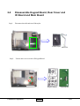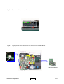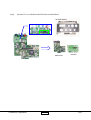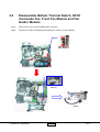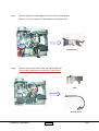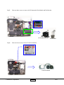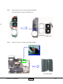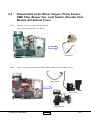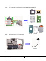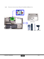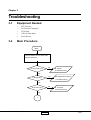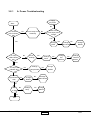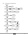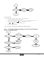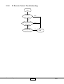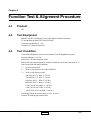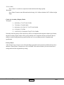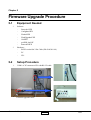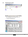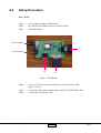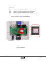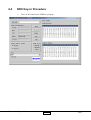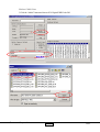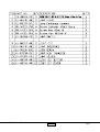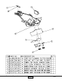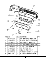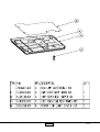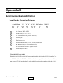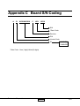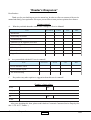
1
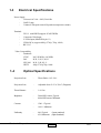
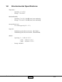
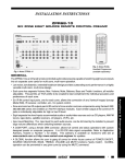
SERVICE MANUAL
Model Name : H31
Prepared by SI :
________________________________________
Prepared by TSE :
________________________________________
Check by :
________________________________________
Approved by :
________________________________________
Date
Revise Version
2005/01/03
V1.0
Description
Initial Issue
Copyright January, 2005 . All Rights Reserved
Document #81G-G04-01A . P/N : 36.81G03.001
Preface
This manual is applied to H31 480P” DMD SVGA Home Theater Projector with digital imaging functionality based on Digital Micro-mirror Device (DMD) technology. It’s the mode of single Panel, 200 watt lamp
and 854(H) x 480(V) resolution. The manual gives you a brief description of basic technical information to
help in service and maintaining the product.
Your customers will appreciate the quick response time when you immediately identify problems that occur
with our products. We expect your customers will appreciate the service that you offer them.
This manual is for technicians and people who have an electronic background. Send the product back to
the distributor for repairing and do not attempt to do anything that is complex or is not mentioned in the
troubleshooting.
NOTICE :
The information found in this manual is subject to change without prior notice. Any subsequent changes
made to the data herein will be incorporated in further edition.
Copyright 2005, January
All Rights Reserved
Manual Version 1.0
Document #81G-G04-01A
I
H31
Table of Contents
Chapter 1
Chapter 2
Chapter 3
Chapter 4
Chapter 5
Introduction
1-1
Product Highlights
Machanical Specifications
Electrical Specifications
Optical Specifications
Environmental Specifications
1-1
1-1
1-2
1-2
1-3
Disassembly Procedure
2-1
Disassemble Lamp Module and Top Cover
Disassemble Keypad Board,Rear Cover, Main BD
and I/O BD
Disassemble Ballast, Thermal Switch, 60*20 intermedia Fan,
Front Fan Module and Fan Guider Module.
Disassemble Color Wheel, Engine, Photo Sensor, DMD chip,
Blower Fan, Limit Switch, Elevator Foot Module and Bottom
Cover
2-1
Troubleshooting
3-1
Equipment Needed
Main Procedure
3-1
3-1
Function Test and Alignment Procedure
4-1
Product
Test Equipment
Test Condition
Service Mode Method
Test Display Modes & Pattern
Inspection Procedure
4-1
4-1
4-1
4-2
4-2
4-5
Firmware Upgrade Procedure
5-1
Equipment Needed
Setup Procedure
Upgrading Procedure
5-1
5-1
5-2
II
2-3
2-6
2-10
H31
Chapter 6
DDC Key-in Procedure
6-1
Equipment Needed
Setup Procedure
DDC Key-in Procedure
6-1
6-2
6-3
Appendix A
Exploded Diagram
7-1
Appendix B
Serial Number System Definition
7-19
Serial Number Format for Projector
7-19
Borad S/N Coding
7-20
Appendix C
Reader’s Response
7-21
I II
H31
Chapter 1
Introduction
1-1
Product Highlights
-
One panel 480P" DMD SVGA projection system with 580 ANSI lumens (Typical) and 490
ANSIlumens.(minimum)
-
200 Watt Lamp
-
Light weight Approx. 4.6 lbs.
-
True 800 * 480 resolution, 16.7M True colors
-
With up, down, left, and right screen reverse
-
Build-in full screen NTSC / PAL / SECAM video capability with S-video / Composite /
Component and HDTV terminals
-
SXGA / XGA / SVGA compatibility with one D-sub input terminal
-
Auto image re-sizing to 854 * 480 full screen
-
Manual focus projection
-
Auto detection of computer signal input
-
Auto Image synchronization (Auto-tracking / frequency / position adjustment)
-
Eco mode supports
1-2
Mechanical Specifications
Dimensions (LxWxH)
-
External 10.7*8.3*3.4 inches (272*210*86mm)
Weight
-
Approximate 4.6 lbs. (2.1 Kg)
Cooling System
-
Four fans with low system acoustic noise level
-
Temperature control circuits with adaptive voltage control
fan speed
Tilt Angle
-
11 degree with elevator mechanism
Keystone correction
-
+/- 16 degrees (32 degrees)
Lamp Door Protection
-
Lamp power supply shut off automatically when door open
Coretronic Corporation
1-1
H31
1-3
Electrical Specifications
Power Supply
Universal AC 100—240V, 50/60 Hz
200W Lamp
Variance FAN speed control (Depend on temperature variant)
Terminals
DVI - I with HDCP(support SCART RGB)
Composite Video Input
S-Video Input (Mini DIN 4-pin *1)
YPbPr RCA (support 480i/p, 576i/p, 720p, 1080i)
RS 232 C
Video Compatibility
Standards :
NTSC
PAL
SECAM
HDTV
1-4
M(3.58 MHz), 4.43 MHz
B, D, G, K, I, M, N
B, D, G, K, K1, L
480p, 576i/p720p, 1080i
Optical Specifications
Projection Lens
-
Throw Ratio=1.65~2.0:1
Projection Lens
-
Adjustable from 31.8” to 330.6” (Diagonal)
Throw Distance
-
1.4~12m
Brightness
-
580 ANSI Lumens, Typical,
490 ANSI Lumens, Minimum
Contrast
-
1500 : 1 Typical
1100 : 1 Minimum
Uniformity
-
90% Typical
(Japan standard)
65% Minimum (Japan Standard)
Coretronic Corporation
1-2
H31
1-5
Environmental Specifications
Temperature :
Operating : 5° to 35°C
Storage : -20° to 60°C
MaximumHumidity
Operating : 5° to 35°C, 80%RH (max), non-condensing
Storage : -20° to 60°C, 80%RH (max), non-condensing
Acoustic Noise Level :
36 ±2 dbA (typical @ 23 + 2° C)
Lamp Life :
2000 hours typical, 50% survival rate (Brite Mode)
3000 hours typical, 50% survival rate (Normal Mode)
Altitude :
-
-
Operating : 0 ~ 2,500 ft 5~35° C
2,500 ~ 5,000 ft 5~30° C
5,000 ~ 10,000 ft 5~25° C
Storage : 40,000 ft
Coretronic Corporation
1-3
H31
Chapter 2
Disassembly Procedure
2-1
Step1:
Disassemble Lamp Module and Top Cover
Turn unit to bottom side and unscrew one screw to remove Lamp Cover
Lamp Cover
Step2:
Unscrew three screws to remove Lamp Module.
Lamp Module
Coretronic Corporation
2-1
H31
Step3:
Unscrew four screws and unplug one connector to remove Top Cover .
Top Cover
Coretronic Corporation
2-2
H31
2-2
Step1:
Disassemble Keypad Board, Rear Cover and
IO Board and Main Board
Disconnect the cable and tear off the mylar.
Insulator Mylar
Step2:
Cable FFC
Unsrew three screws to take off Keypad Board.
Keypad Buttom
Coretronic Corporation
2-3
Keypad Board
H31
Step3:
Unscrew two hex screws and two screws.
Step4:
Unplug eleven wires and unscrew five screws to remove Main Board.
Main Board Module
Coretronic Corporation
2-4
H31
Step5:
Separate IO Cover Module and IO Board from Main Board.
IO Cover Module
Main Board
Coretronic Corporation
2-5
IO Board
H31
2-3
Step1:
Step2:
Disassemble Ballast, Thermal Switch, 60*20
intermedia Fan, Front Fan Module and Fan
Guider Module
Unscrew five screws to put Ballast aside to the unit.
Separate one cable from Bushing and unplug two cables to remove Ballast.
Bushing
Ballast
Coretronic Corporation
2-6
H31
Step3:
Unscrew eight screws and unplug one wire to remove LVPS Module.
Unscrew 1 screw to remove the Thermal Sensor(in the blue circle).
LVPS Module
Step4:
Unscrew one screw to remove Plate and Thermal Switch*.
*Notice: Be careful not to scratch the Color Wheel.
Plate
Thermal Switch
Coretronic Corporation
2-7
H31
Step5:
Unscrew three screws to remove 60*20 Intermedia Fan Module and Fan Bracket..
60*20 Intermedia Fan
Step6:
Fan Bracket
Unscrew four screws to remove Front Fan Module.
Front Fan Module
Coretronic Corporation
2-8
H31
Step7:
Unscrew three screws to remove Front Fan Module.
Tear off the Mylar to remove the IR Receiver.
MM
Mylar
Fan Bracket System Fan
Top Cover
Step8:
Unscrew one screw to remove Fan Guider Module.
Fan Guider Module
Coretronic Corporation
2-9
H31
2-4
Step1:
Disassemble Color Wheel, Engine, Photo Sensor,
DMD Chip, Blower Fan, Limit Switch, Elevator Foot
Module and Buttom Cover
Unscrew one screw to remove Color Wheel*.
Notice: Do not scratch the Color Wheel.
Color Wheel
Step2:
Unscrew seven screws to remove Engine Module, Blower Fan and Photo Sensor.
Photo Sensor
Blower Fan
Engine Module
Coretronic Corporation
2-10
H31
Step3:
Tear off Mylar and unsrew four screws to remove DMD Board and DMD Chip.
DMD Socket
DMD Thermal Pad
DMD Chip
DMD Board
Heat Sink
Heat Mylar
Step4:
Heat Sink
Unscrew two screws to remove Limit Switch.
Limit Switch
Coretronic Corporation
2-11
H31
Step5:
Unscrew two screws to remove Elevator Foot Module and Bottom Cover.
Bottom Cover
Foot
Coretronic Corporation
2-12
Gear Bar
Spring
Base Holder
H31
Chapter 3
Troubleshooting
3-1
Equipment Needed
•
•
•
•
•
3-2
H31 Projector
PC (Personal Computer)
VGA Cable
Video/S-Video Input
Screw Drivers
Main Procedure
Start
Connect Power cord, S-Video and
then turn power on
No
Is Lamp light on ?
A. Power
Troubleshooting
Yes
No
Is Image OK ?
B. Image Performance
Troubleshooting
Yes
No
Is function OK ?
C. Function
Troubleshooting
Yes
1
Coretronic Corporation
3-1
H31
1
Yes
Is Remote
Control OK?
No
D.Remote control
Troubleshooting
Yes
No Fault Found
End
Coretronic Corporation
3-2
H31
3-2.1
A. Power Troubleshooting
Supply
AC power
Start
No
Is Power
LED indicator
OK ?
No
Check Lamp Cover
assembly
Check Power
cord & input power
voltage
No
Yes
Yes
Change No
LVPS
Is Temp
LED indicator
OK ?
Is Fan
No
No
Change
LVPS
working ?
No
Change No
Main Board
Change
Fan
Module
No
Change
Ballast
Change
Thermal
Sensor
Yes
No
Is Lamp LED
indicator OK ?
Change
Lamp Module
No
No
Change
Change
Ballast
Yes
Light doesn’t
work
No
Change
Ballast
Main Board
Yes
Fail
No
to light
Change
Lamp
No
Change
Ballast
Yes
End
Coretronic Corporation
3-3
H31
3-2.2
B. Performance Troubleshooting
Start
have
signal
Yes
Have image ?
No
change
cable
No
Change
M/B
Change
DMD
Board
No
No
Yes
Display Abnormal ?
Yes
No
Change
M/B
Change
DMD
Chip
Change
DMD Board
No
No
Have bar at the
right & left side of
image ?
Change
DMD Board
Yes
Uniformity OK ?
No
Change
Engine Module
Yes
Is color OK ?
No
Yes
Color Adjust
Procedure
* Note 1
No
Change
M/B
No
Change
DMD Board
Dot defect isn’t
compliant with the
spec.?
Yes
Change
DMD Chip
No
Change
Engine
Module
No
Have line bar ?
Yes
Adjust
frequency
No
Change
M/B
1
Coretronic Corporation
3-4
H31
1
No
Have noise ?
Adjust
tracking
Yes
No
Change
M/B
No
End
Color Adjust Procedure :
Notice : PC shall run 64 Intensity for Primary Colors Pattern of DMW Program.
Power on.waiting for the "No Signal" show on the screen.
1.
Press "Up" ,"Enter" button at the same time twice, then press "Left" ,"Enter" button at the same time twice.
2.
Connect PC signal, then press “
” button to enter “Display Source” function.
3.
Press “ ” or “ ” to choose “Color Wheel Index” function.
4.
Press “+” or “-” button to adjust.
. Note 1 : It may need to be used when you replace Main Board or Optical Engine alone.
3-2.3
C. Function Troubleshooting(see 3-2.4 to check the Remote
Control Troubleshooting)
Start
Does OSD show
up ?
No
Yes
Can function be
adjusted ?
Remote control
and Keypad Board
don’t work
Change
FPC
Change
Keypad
Board
Change
Main Board
Change
Main board
No
Change Main
Board
Yes
Can OSD data
be saved ?
Change
No
Keypad Board
No
Yes
No
No
No
Change
Main board
Yes
End
Coretronic Corporation
3-5
H31
3-2.4
D. Remote Control Troubleshooting
Start
Replace
the battery
Yes
No
Yes
Change Remote
Controller
No
Yes
Change M/B
Coretronic Corporation
End
3-6
H31
Chapter 4
Function Test & Alignment Procedure
4-1
Product
-
4-2
Test Equipment
-
4-3
H31
IBM PC with XGA resolution (Color Video Signal & Pattern Generator)
VCR with Multi-system(NTSC/PAL/SECAM)
Chroma meter Minolta CL-100
Chroma 2327 (Pattern Generator)
Test Condition
-
-
Circumstance Brightness : Dark room less than 2.5 lux (for Brightness measure)
Inspection Distance : 2.5~3m
Screen Size : 60 inches diagonal (wide)
Before function test and alignment, each H31 should be run-in and warmed-up for at
least 2 hours with following conditions.
1.) In room temperature
2.) With cycled display colors (R,G,B,White)
3.) With cycled display modes
640*480 (H=37.5 KHz, V=75 Hz)
720*400 (H=31.5 KHz, V=70 Hz)
800*600 (H=53.7 KHz, V=85 Hz)
800*600 (H=37.9 KHz, V=60 Hz)
1024*768 (H=48.4 KHz, V=60 Hz)
1024*768 (H=68.7 KHz, V=85 Hz)
1024*1024 (H=63.98 KHz, V=60 Hz)
Test Display Mode & Pattern (Refer to 4-4.1 & 4-4.2)
Function Test and Alignment Procedure
Coretronic Corporation
4-1
H31
4-4
Test Display Modes & Pattern
4-4.1
Compatible Modes
Analog :
Compatibility
Re s olution
V-Sync(Hz)
H-Sync(KHz)
VGA
640*480
75
37.5
VGA
640*480
85
43.3
VGA
720*400
70
31.5
VGA
720*400
85
37.9
SVGA
800*600
56
35.2
SVGA
800*600
60
37.9
SVGA
800*600
72
48.1
SVGA
800*600
75
46.9
SVGA
800*600
85
53.7
XGA
1024*768
43.4
35.5
XGA
1024*768
60
48.4
XGA
1024*768
70
56.5
XGA
1024*768
75
60.0
XGA
1024*768
85
6 8 .7
SXGA
1280*1024
60
63.98
Coretronic Corporation
4-2
H31
4-4.2
Function Test Display Pattern
Ite m
Te s t Conte nt
Patte rn
Spe cification
R e mark
1
Frequency & Phase
Fine Line Moire
Eliminate visual wavy noise.
Figure 1
2
Contrast/Brightness
Gray Scale
Gray levels should be distinguishable.
Figure 2
3
R, G, B and White
Color Performance
R, G, B and
White Color
Each R, G, B color should be normal.
Figure 3~6
4
Screen Uniformity &
Flicker
Full White
Should be compliant with the spec.
Figure 6
5
Dead/Blemish Pixel
R, G, B, White,
Dark, Blue 60,
Gray 30
The numbers of dead/blemish pixels should
be compliant with the spec.
Figure 3~9
6
Boundary
Boundary Frame
Horz. and Vert. position of video shuld be
adjustable to be within the screen frame.
Figure 10
7
HDTV
Color Bar
N o discolor
Figure 11
8
DVI
Genera- 1
image should be normal
Figure 12
Fine Line Morie Pattern (Figure 1)
64-Gray Scale pattern (Figure 2)
R. Color Pattern (Figure 3)
Coretronic Corporation
G. Color Pattern (Figure 4)
4-3
H31
B. Color Pattern (Figure 5)
Full White Pattern (Figure 6)
Dark Pattern (Figure 7)
Gary 30 Pattern (Figure 8)
Blue 60 Pattern (Figure 9)
Boundary Frame (Figure 10)
Color Bar (Figure 11)
Coretronic Corporation
General-1 (Figure 12)
4-4
H31
4-5
Inspection Procedure
RESET :
Please press “Menu” button on the projector panel to enter Service Mode, then press “ “ or “ “ to
choose “Management” function. Press “ “ button to choose “Machine Reset” function, then press “ “
to check if it works. This action will allow you to erase all end-user’s settings and restore the original
factory setting.
Frequency and Phase :
Test Signal : 800*600 @ 85Hz
Test Pattern : Line Moire Pattern
Check and see if image sharpness and focus is well performed.
If not, readjust by following steps.
1.) Enter “Image” menu and select “Frequency” Function to adjust the total pixel number of pixel
clock in one line period.
2.) Then select “Phase” Function and use right or left arrow key to adjust the value to minimize
video flicker.
R, G, B and White Colors Contrast :
Test Signal : 800*600 @ 85Hz
Test Pattern : 64 or 16 R, G, B and White colors Intensities Pattern
Please check and see if each colors is normal and distinguishable.
If not, please return the unit to repair area.
Screen Uniformity and Flicker :
Test Signal : 800*600 @ 85Hz
Test Pattern : Full White Pattern
Please check and see if it’s in normal condition.
If not, please return the unit to repair area.
Dead Pixel/Blemish Pixel :
Test Signal : 800*600 @ 85Hz
Test Pattern : Gray 30, Blue 60, White, Dark, Red, Green and Blue Pattern
Please check and see if there are dead pixels on DMD chip.
The total numbers and distance of dead pixels should be complaint with specification.
Specification:
1. It can’t have any dead pixel/
2.DMD chip can’t blemish pixel.POS allows one blemish pixel.
Coretronic Corporation
4-5
H31
Brightness:
Enter “Service Mode” and select spoke on.
Select White to test bright screen.
Select Dark to test dark screen.
Specification:
Brightness 490 Lumen
Balance 65%
Contrast
1100
-Remote control:
Press Power botton of remote control to test Indicator light
Press Menu botton of remote control to test functions
-HDTV:
Using the following table with chroma 2327
Time
Pattern
480P
Color Bar
780P
Color Bar
1080P
Color Bar
-DVI
Using the following table with chroma 2316
Time
Pattern
8 5 4 * 4 8 0 -6 0 H z
6 4 -Gray Scale Pattern
8 5 4 *4 8 0 -6 0 Hz
Gen eral-1
-S-video/video
Press “Source” button to switch to S-video and video mode and check the image quality.
Coretronic Corporation
4-6
H31
-Ycb cr (480i)
Press “Source” to switch to component-I mode and check the iamge quality.
-Brit-mode:
Press “Menu” botton to enter Brit-mode and selecting “On” will have dark and “Off” will have bright
iamge.
Check for Secondary Display Modes
Test signal :
1.) 640*480 @ 72.81/75.00/85.01Hz
2.) 720*400 @ 70.08/85.04Hz
3.) 800*600 @ 56.25/60.32/72.19/75.00/85.06Hz
4.) 832*624 @ 74.55Hz
5.) 1024*768 @ 43.48/60.00/70.00/75.03/85.00Hz
Normally when the primary mode 800*600 @ 85Hz is well adjusted and complaint with the specification,
then the secondary display modes will be great possibility to be complaint with the specification. But we
still have to check with general test pattern to make sure every secondary modes is complaint with
specification.
Factory Reset :
After final QC step, we have to erase all saved change again and restore the factory defaults. Please select
and enter “Factory Reset” Function to see if it is workable. This action will allow you erase all end-user’s
settings and restore the original factory setting.
Coretronic Corporation
4-7
H31
Chapter 5
Firmware Upgrade Procedure
5-1
Equipment Needed
*
*
5-2
Software :
Bootcode.HEX
Configdata.HEX
Flasher.HEX
FlashUpgrader.EXE
Gui.HEX
pwSDK_8m.INF
Romcode.HEX
Hardware :
RS232 to mini din 3 Pin Cable (PN:42.86301.001)
PC
H31
Setup Procedure
1.
COM 1 of PC connects to H31 with RS-232 cable.
Firmware upgrade Fixture
Coretronic Corporation
5-1
H31
5-3
Upgrading Procedure
1.
Execute “FlashUpgrader.exe”.*
* : Note1:Flash Upgrader operates on Windows 98 , ME
Note 2: Flash UpgraderNT operates onWindows 2000, NT, XP.
2.
The window of FlashUpgrader shows up.
Click “Choose” to get the file directory.
pwSDK_8m.inf
Coretronic Corporation
5-2
H31
3.
Select <pwSDK_8m.inf> file and open it.
H31
pwSDK_8m
1
2
pwSDK_8m
4.
5.
Select the serial port which is connected with the fixture.
Don’t use other baud rate less than 115200, or the program may not work.
Hold Power button and then click Flash icon. Power button must be held till
the Downloading gui.hex appears (as the following two pictures indicate )
pwSDK_8m.inf
Coretronic Corporation
5-3
H31
pwSDK_8m.inf
6.
Wait for finish.
7.
After all files are downloaded, the unit will start up automatically to finish firmware
upgrade .
pwSDK_8m.inf
8.Factory reset
Coretronic Corporation
5-4
H31
H31 Enter the service mode produce :
1.
2.
Power on.waiting for the "No Signal" show on the screen.
Press "Up" ,"Enter" button at the same time twice.then press "Left" ,"Enter" button at the same time
twice.
H31 Logo Change Procedure!!
1.
2.
3.
4.
5.
Enter service mode.
Move the cursor to “Display Source” selection.
Press and hold on “Up” and ”Left” control button at the same time, then press “Down” button.
There will be a “Logo Select” function enable.
Enter the “Logo Select” for the Logo change.
Coretronic Corporation
5-5
H31
Chapter 6
DDC Key-In Procedure
6-1
Equipment Needed
-
EDID Fixture
Both old and new version EDID Fixtures can use and please choose match one (IC:Generic)
PC set
DFP-DVI Cable(42.81702.001)
Power Cord
Power Adapter
H31 Projector
EDID Driver
RS232 cable
Power Adapter
RS232 Cable
EDID Fixture (Old Version)
Coretronic Corporation
DFP-DVI Cable
EDID Fixture (New Version)
6-1
H31
6-2
Setup Procedure
Old Version
Step1.
Step2.
Step3.
Connect Power Adapter with the fixture.
JP1 and JP5 on the fixture are close, and JP2 is open.
Turn on the fixture.
Power Adapter
P1
Power Switch
P2
P3
(Figure 1 : Flash Board)
Step4.
Step5.
Step6.
Connect P1 of the fixture with COM1 port of PC by RS232 cable.
(Figure 1 and 2)
Connect P3 of the fixture with the DVI port of H31 by DFP-DVI cable.
Connect H31 with Power Cord.
Coretronic Corporation
6-2
H31
New Version
Step1.
Step2.
Step3.
Step4.
Connect Power Adapter with the fixture.
Connect P1 of the fixture with COM1 of PC by RS232 cable.
Connect P3 of the fixture with DVI port of DVI-DVI cable.
Plug Power Adapter to the fixture and connect the H31 Power Cord.
*Notice : Confirm JP3 is “Close” status (EDID Mode).
P3
P2
P4
JP3
Power Adapter
P1
(Figure 2 : Finish Setup)
Coretronic Corporation
6-3
H31
6-3
DDC Key-in Procedure
1.
Turn on H31 and execute EDID.exe program .
Coretronic Corporation
6-4
H31
2.Select COM 1 Port.
3.Click the “Model” button and choose H31 Digital EDID Code.INI
2.
1.
3.
4.
Coretronic Corporation
6-5
H31
4. Click “Program” after inputing the Serial Number.
1.
2.
5.Click “OK” after this message below emerges
Coretronic Corporation
6-6
H31
6.Input is done after the “OK” message shows(in the red circle).
Coretronic Corporation
6-7
H31
7. Please mark both “Digital” and “Trans” in the “Read Item” in red circle.
(Note 1 : If EDID informations can’t match with “Barcode” , please cancel “Trans” item and
click “Read” button again.)
8.Then click the “Read” button.
(Note 2 : Exit the program and restart your system when needs to burn EDID again.)
9.Inspect if the week and the last digits of the Serial number are correct or not.
2.
3.
1.
Coretronic Corporation
6-8
H31
Appendix A
Exploded Diagram
Coretronic Corporation
7-1
H31
Coretronic Corporation
7-2
H31
Coretronic Corporation
7-3
H31
Coretronic Corporation
7-4
H31
Coretronic Corporation
7-5
H31
Coretronic Corporation
7-6
H31
Coretronic Corporation
7-7
H31
Coretronic Corporation
7-8
H31
Coretronic Corporation
7-9
H31
Coretronic Corporation
7-10
H31
Coretronic Corporation
7-11
H31
Coretronic Corporation
7-12
H31
Coretronic Corporation
7-13
H31
Coretronic Corporation
7-14
H31
Coretronic Corporation
7-15
H31
Coretronic Corporation
7-16
H31
Coretronic Corporation
7-17
H31
Coretronic Corporation
7-18
H31
Appendix B
Serial Number System Definition
Serial Number Format for Projector
A BBB Y WW C D BEMO EEEE
1
2
3
4
5
6
7
1
:
A = Optoma, B~Z = OEM
2
:
Product code (ex: 81G = H31)
3
:
Y = Last number of the year (ex: 2004 - 4)
4
:
Week of year
5
:
Panel vendor code
6
:
Electrical classification (1=110V, 2=220V, 0=universal)
7
:
B = BIOS version, E = PCB board version,
8
M = Mechanical version, O = Optical version
8
:
Serial code (from 0001~)
EX : A81G429T0AAAA1001
This label “A81G429T0AAAA1001” represents the whole serial number for H31, including Ver.
1st of BIOS and Ver. 1 of PCB Board. Both mechanical and optical version are 1st. In addition,
panel vendor is T1. It’s produced on 29-week of 2003 for universal area and its serial code is 1001.
Coretronic Corporation
7-19
H31
Appendix C Board S/N Coding
A
B
XXXXXXXXXX
C
XXX
XXXX
S/N
*Date Code
Revision
P/N
Vendor Code
ID
B. DMD BD
C. MAIN BD
*Date Code : Year(1 digit)+Week(2 digits)
Coretronic Corporation
7-20
H31
*Reader’s Response*
Dear Readers:
Thank you for your backing our service manual up. In order to refine our content of the service
manual and satisfy your requirement. We expect you can offer us some precious opinions for reference.
Assessment:
A.
What do you think about the content after reading H31 Service Manual?
Unit
Ex cellent
G ood
Fair
Bad
1. Introduction
2. Disassembly Procedure
3. Troubleshooting
4. Function Test & Alignment Procedure
5. Firmware Upgrade Procedure
6. DDC key- in Procedure
7. Touch Panel Driver Installation and Calibration
8. Appendix
B.
Are you satisfied with the H31 service manual?
It em
Ex cellent
G ood
Fair
Bad
1. Service Manual Content
2. Service Manual Layout
3. The form and listing
C.
Do you have any other opinion or suggestion about this service manual?
Reader’s basic data:
Name:
Title:
Company:
Add:
Tel:
Fax:
E- mail:
After your finishing this form, please send it back to Coretronic Customer Service Dept. by fax:
886-3-578-8357, Thanks :)
Coretronic Corporation
7-21
H31