1
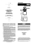
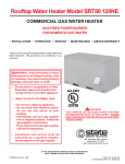
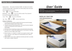
D
Service Manual
Table of Contents
Key Pad ....................................................................................................01
Master Programming .............................................................................02
Product Features .....................................................................................08
Dimensional Drawing .............................................................................11
Control Drive Assembly .........................................................................12
Powerhead Assembly .............................................................................14
3/4"Electric Meter Assembly ................................................................15
Valve Wiring Diagram ............................................................................16
Www.fobrite.com
Key Pad
Move the cursor to the parameters for change.
①Increase the value of the selected parameters.
②Confirm the selected parameters.
Set the current time and day.
Select the valve regeneration type.
There are 4 options-Timer, Meter immediate, Meter delay and Week day initiated regenerations.
Depending on the above MODE selected, to set the appropriate information such as the
regeneration time, water capacity, etc.
Set the duration of Backwash, Brine Draw, Rapid Rinse, and Brine Fill.
Manually initiate an immediate regeneration or a queued regeneration.
01
Master Programming
Time & Day
For example to set the valve at: 2︰30 AM WED
Flashing
12 : 00 PM
MON TUE WED THU FRI SAT SUN
Default setting
Flashing
02 : 00 AM
SUN
MON TUE WED THU FRI SAT SUN
Increase the number to“02:00”AM
and PM will automatically change
according to the hours changing
Flashing
02 : 00 AM
SUN
MON TUE WED THU FRI SAT SUN
Move the cursor
Flashing
02 : 30 AM
SUN
MON TUE WED THU FRI SAT SUN
Increase the number to“30”
02 : 30 AM
Move the cursor
SUN
MON TUE WED THU FRI SAT SUN
Flashing
02 : 30 AM
SUN
MON TUE WED THU FRI SAT SUN
Once confirm the set,the
cursor will automatically jump
to the next
Flashing
Save & Exit. Please don't forget to press again this button.
Otherwise the program will not exit to the main menu.
If you do not press the button within 5 minutes, the changes made will not be saved to memory.
The display will return to service position.
02
Master Programming
MODE
For example to set the valve in: Meter Imm.
3
Unit: M
Flashing
Ti me
Met er Imm.
Week
Met er Del ay
Default setting
Flashing
Ti me
Met er Imm.
Week
Met er Del ay
Move the cursor
Flashing
3
M
GAL
L
Default setting
Flashing
3
M
GAL
L
Once confirm the set,the cursor
will automatically jump to the next
Save & Exit. Please don't forget to press again this button.
Otherwise the program will not exit to the main menu.
If you do not press the button within 5 minutes,the changes
made will not be saved.Then the display will return to service position
Revi ew
Day
Over ride
Once MOD E Change!
Display returns to service position after
7 seconds.or press any button
Note:
Valve " MODE " always set piror to " SET REGEN ." Once change the " MODE " setting ,
Please review and change the contents inside "SET REGEN" accordingly
03
Master Programming
SET REGEN.(TIME MODE)
For example to set the regeneration at: 02︰30 AM Day Override: 05
Flashing
02 : 00 AM
Day Overrid e
03
Default setting
Flashing
02 : 00 AM
Day Overrid e
03
Move the cursor
Flashing
02 : 30 AM
Day Overrid e
03
02 : 30 AM
Day Overrid e
03
Increase the number to “30”
Move the cursor
Flashing
02 : 00 AM
Day Overrid e
05
Increase the number to “5”
Flashing
Save & Exit. Please don't forget to press again this button.
Otherwise the program will not exit to the main menu.
If you do not press the button within 5 minutes, the changes made will not be saved to memory.
The display will return to service position.
04
Master Programming
SET REGEN.(WEEK MODE)
For example to set valve regeneration at: 02︰00 AM FRI & SUN
Flashing
02 : 00 AM
MON TUE WED THU FRI SAT SUN
02 : 00 AM
MON TUE WED THU FRI SAT SUN
Default setting
Move the cursor
Flashing
02 : 00 AM
MON TUE WED THU FRI SAT SUN
Cancel the default setting “WED”
Cursor will automatically jump to
the next
Flashing
02 : 00 AM
MON TUE WED THU FRI SAT SUN
Move the cursor
Flashing
02 : 00 AM
MON TUE WED THU FRI SAT SUN
Confirm the set,the cursor will
automatically jump to the next
Flashing
02 : 00 AM
MON TUE WED THU FRI SAT SUN
Move the cursor
Flashing
Flashing
02 : 00 AM
MON TUE WED THU FRI SAT SUN
Confirm the set,the cursor will
automatically jump to the next
Save & Exit. Please don't forget press again this button.
Otherwise the program will not exit to the main menu.
If you do not press the button within 5 minutes, the changes made will not be saved to memory.
The display will return to service position.
05
Master Programming
SET REGEN.( METER IMM & METER DELAYED MODE )
For example, to set the valve under 1600 L Capacity, Regeneration time 02:30 AM and Regeneration
override day 6.
NOTE:
Flashing
Default setting for standard
02:00 AMthe Regeneration
Day:OFF Override
When meter Valve activated
Day function, the valve will
METER valve,the Regeneration Day
Capacity
000016 00 L
Override
function
is reached
OFF.
then be force to regenerate at the time whenever the set
time or
capacity
first.
Flashing
02:00 AM
Day:OFF
Capacity
00001600 L
Move the cursor
to set the regeneration time
02:30 AM
Day:OFF
Capacity
00001600 L
Increase the number to “30"
Flashing
Flashing
02:30 AM
Day:OFF
Capacity
00001600 L
Move the cursor to check whether activate
the Regeneration Day Override function.
If NOT, just skip and move the cursor to the
next position.
Flashing
02:30 AM
Day:06
Capacity
00001600 L
To activate the Regeneration Day Override
function by just press the
button.
Then increase the number to“06"
To CANCEL it ,increase the number to“99”,then the next is“OFF”
02:30 AM
Day:06
Capacity
00001600 L
Move the cursor
to set the Capacity
Flashing
02:30 AM
Day:06
Capacity
00001000 L
Increase the number to “0"
Flashing
SAVE & EXIT. Please don't forget to press this button, otherwise the program will not
return to the main menu.
If do not pressure any button within 5 minutes, the changes made will not be saved and
the display will automatically return to the service position.
06
Master Programming
SET CYCLE.
Flashing
Ba ckWa s 01 5
Br ine Dr 06 0
Ra pi dR s 01 0
Re Fi ll
01 2
Default setting
every cycle time can be set to“000”
as requested
Move the cursor
Increase the number
Save & Exit. Please don't forget to press again this button.
Otherwise the program can not exit to the main menu.
If you do not press the button within 5 minutes, the changes made will not be saved to memory.
The display will return to service position.
07
Product Features
1. Full & clearly display in the Ser vice position
12 :00 PM
Serv ice
Timed Regeneration mode
The Display will show the current time, Day of the week,
and remaining time to the next set regeneration.
Service
Meter Immediate Regeneration mode
The Display will show the current time, Day of the week,
and the remaining treated water to the next regeneration.
SUN
02day02h00min
12:00 PM
SUN
0001600 GAL
12:00 PM
SUN
0001600 GAL
12:00 PM
Service
SUN
02h00min
Meter Delay Regeneration mode
The Display will show the current time, Day of the week
and the remaining treated water. When the remaining
treated water counts down to zero, the display changes
to show the remaining time to the next set regeneration.
Service
12:00 PM
SUN
2day02h00min
WED
Servic e
Weekly Regeneration mode
The Display will show the current time, Day of the week,
and the remaining time to the next set regeneration, and
the day of the next regeneration.
2. Automatic Key pad lock
If the key pad is not used for 3 minutes, the keyboard will be locked. To release, press any key to
illuminate the screen then press buttons as shown.
Press
and then
3. Memory during power failure
● All program settings are stored in permanent memory. Current valve position, cycle step elapsed,
time of day are stored during the power failure. Reset of current time is necessity when power up
.
● If the valve stopped at a regeneration stage when power failure, the valve will return to the prior
position when power up. It takes 4 to 5 minutes to reset to the position.
Resetting
08
Product Features
4. Restore factory settings
Press and hold the button “Manual Regen.”, then power up the valve,the display shows :
Factory settings
have been Restored
Release the button “Manual Regen.”,then the valve will restore to the factory default settings.
5. Fault alarm
The system will automatic detect errors, if system errors are found, the display shows:
System Err
Please reset
In this state, Please cut off the power supply, and then re-apply the power, if the errors are
removed the valve will either stop in service position or reset, If errors persists, contact your
local supplier for more assistance.
6. No hard water bypass
D series valves is designed with the option of no hard water bypass piston, which is ensured of
free hard water out of the outlet in the process of regeneration.
7. Manual regeneration
● Queueing a Regeneration
When the valve is in ser vice position,Press the button“Manual Regen.”,The“Que.Reg.” Icon
will appear to indicate that a regeneration is queued.To cancel a queued regeneration,press the
button“Manual Regen.”Again.
Queueing a Regeneration means the system will initiate a regeneration at the time set at the
same day. If itˊs missed, the system will initiate a regeneration at the same time of the next day.
12:00 PM
02h00min
SUN
Que.Reg
12:00 PM
02h00min
Service
In the mode of TIME or WEEK, The display shows for the
Queued Regeneration.
Service
In the mode of METER DELAY ,The display shows for the
Queued Regeneration.
SUN
Que.Reg
12:00 PM
SUN
0001600 GAL
Service
Alternating display
12:00 PM
02h00min
SUN
Que.Reg
In the mode of METER IMMEDIATE ,The display shows for
the Queued Regeneration.
The system will initiate a regeneration either the treated
water remaining counts down to zero or the remaining
time counts down to zero, whichever is first.
Service
09
Product Features
● Regenerating Immediatel y
When the valve is in service position,press and hold the button“Manual Regen.”at least 5 seconds,
the valve immediately advances to the regeneration.
12 :00 PM
SUN
GO TO Back Wash
12 :00 PM
015
“GO TO BackWash” Flashing
SUN
min Back Wash
When the time counts down to zero or press“Manual Regen.”
12 :00 PM
SUN
GO TO Bri neDra w
12 :00 PM
“GO TO BrineDraw” Flashing
SUN
060 min Bri neDra w
When the time counts down to zero or press“Manual Regen.”
12 :00 PM
SUN
GO TO RapidRinse
12 :00 PM
010
“GO TO Rapid Rinse” Flashing
SUN
min RapidRinse
When the time counts down to zero or press “Manual Regen.”
12 :00 PM
SUN
“GO TO ReFill” Flashing
GO TO Refill
12 :00 PM
012
SUN
min
Refill
When the time counts down to zero or press “Manual Regen.”
12 :00 PM
SUN
“GO TO Service” Flashing
GO TO Serv ice
10
Dimensional Drawing
11
Control Drive Assembly
12
Control Drive Assembly
Item No.
Quantity
Part No.
1 ……………………… 1 ……………………… 66162 .............................
2 ……………………… 2 ……………………… 02011 .............................
3 ……………………… 1 ……………………… 66165 .............................
4 ……………………… 4 ……………………… 02012 .............................
5 ……………………… 3 ……………………… 02002 .............................
6 ……………………… 1 ……………………… 56115 .............................
7 ……………………… 1 ............................ 50045-1 ...........................
8 ……………………… 5 ……………………… 56033 .............................
9 ……………………… 4 ……………………… 56004 .............................
10 ……………………… 1 ……………………… 50039 .............................
11 ……………………… 1 ……………………… 56072 .............................
12 ……………………… 1 ……………………… C1025 ............................
13 ……………………… 1 ..........................................................................
14 ……………………… 1 ……………………… 50009-1 ...........................
15 ……………………… 1 ……………………… 50011 ............................
16 ……………………… 4 ……………………… 01013 ............................
17 ……………………… 1 .........................................................................
18 ……………………… 2 ……………………… 56017 ………………………
19 ……………………… 2 ……………………… 56051 ………………………
20 ……………………… 2 ……………………… 02105 ………………………
21 ……………………… 1 ……………………… 01007 ………………………
22 ……………………… 1 ……………………… 01102 ………………………
23 ……………………… 1 ……………………… 56015 ………………………
24 ……………………… 1 .........................................................................
25 ……………………… 1 ……………………… 01004 ………………………
26 ……………………… 1 ……………………… 56056 ………………………
27 ……………………… 1 ……………………… 56060 ………………………
28 ……………………… 1 ……………………… 56062 ………………………
29 ……………………… 1 ……………………… 56023 ………………………
30 ……………………… 1 ……………………… 56061 ………………………
31 ……………………… 1 ……………………… 50001 ………………………
32 ……………………… 1 ……………………… C1012 ............................
33 ……………………… 1 ………………………..............................................
34 ……………………… 1 ………………………..............................................
35 ……………………… 1 ……………………… 50060 ………………………
36 ……………………… 1 ……………………… 50005 ………………………
37 ……………………… 1 ……………………… 01105 ………………………
38 ……………………… 1 ……………………… 56010 ………………………
39 ……………………… 1 ……………………… 01003 ………………………
40 ……………………… 1 ……………………… 66119 ………………………
41 ……………………… 1 ……………………… 56058 ………………………
42 ……………………… 1 ……………………… A1039 ………………………
43 ……………………… 1 ……………………… 04001 ………………………
44 ……………………… 1 ……………………… 04053 ………………………
45 ……………………… 1 ……………………… C1024 ………………………
46 ……………………… 1 ……………………… C1026 ………………………
47 ……………………… 1 ……………………… 50040-1 ..........................
48 ……………………… 1 ……………………… 50008 ………………………
49 ……………………… 1 ……………………… 56101 ………………………
50 ……………………… 1 ……………………… 56102 ………………………
51 ……………………… 1 ……………………… C1023 ............................
52 ……………………… 1 ……………………… 50025 ............................
53 ……………………… 1 ……………………… 66500 ............................
When D.L.F.C Button
■
※ More Model Options
less than or equal to 7.0gpm, use the parts
13
Description
End Plug Assembly
Screw
Piston Rod Assembly
Screw
Screw
Piston Retainer
Piston Softener
Seal
Spacer
Vice Spacer
Straight Drain Barb
Drainage Adapter
D.L.F.C Button
Valve Body
Drain Hose Bolt
O-Ring
Yoke
Adapter coupling
Adapter Clip
Screw
O-Ring
O-Ring
B.L.F.C Button Retainer
B.L.F.C Button
O-Ring
Brine Valve Connector
Screen, Brine Line
B.L.F.C Tube Insert
B.L.F.C Ferrule
B.L.F.C Fitting Nut
Brine Cover
Injector Plug
Injector nozzle
Injector throat
Middle Ring
Filter
O-Ring
Spacer
O-Ring
Brine Valve Cap Assembly
Spring
Brine Piston Assembly
Washer
Retaining Ring
Piston Rod Assembly
Piston-P Assembly
Piston
Spacer Mat
B.L.F.C Plug
B.L.F.C Plug
Drain Hose Barb
D.L.F.C Button Retainer
Mix Water Valve Assembly
Powerhead Assembly
Item No.
1
2
3
4
5
6
7
8
9
10
11
12
13
14
15
16
17
18
※19
20
21
Quantity
Part No.
……………………… 1 ………………………
……………………… 1 ………………………
……………………… 1 ………………………
……………………… 1 ………………………
……………………… 1 ………………………
……………………… 2 ………………………
……………………… 2 ………………………
……………………… 12 ………………………
……………………… 6 ………………………
……………………… 1 . ............................
……………………… 1 ………………………
……………………… 1 ………………………
……………………… 1 ………………………
………………………
………………………
………………………
………………………
………………………
………………………
………………………
………………………
1
1
1
1
1
1
1
1
22 ……………………… 1
Description
50023 ………………………
50016 ………………………
50015 ………………………
C0001 ………………………
06051 ………………………
06003 ………………………
02081 ………………………
02106 ………………………
02110 ………………………
07037 .............................
50014 ………………………
50092 ………………………
50018 ………………………
50028 ………………………
……………………… 50024 ………………………
……………………… 50013 ………………………
……………………… 04002 ………………………
……………………… 00105 ………………………
……………………… 13265 ………………………
.....................................................................
……………………… 07021 ………………………
……………………… 50017 ………………………
50027 ………………………
……………………… 07019 ………………………
※ More Model Options
14
Cover
Brine Valve Gear
Drive Gear
Wiring Harness
Insulation
Switch
Screw
Screw
Screw
Circuit Board
Front Cover
Label
Drive Cam(No Hardwater)
Drive Cam(Hardwater)
Positioning Bracket
Bracket
Seal
Pin
Motor
Transformer
DC Monotrematous Socket
Brine Cam(No Hardwater)
Brine Cam(Hardwater)
Strain Relief
3/4’’ Electric Meter Assembly
3/4"Turbo Electric Meter Assembly Parts List
Item No.
Quantity
Part No.
Description
1
2
3
4
5
6
………………………
………………………
………………………
………………………
………………………
………………………
1
1
4
1
2
2
………………………
………………………
………………………
………………………
………………………
………………………
56013 ………………………
50022-1 ……………………
01013 ………………………
1220E ………………………
50044 ………………………
02105 ………………………
Flow Straightener
Meter Cable Assembly
O-ring,Meter Body
Meter Body Assembly
Adapter Clip
Screw
3/4"Impeller Electric Meter Assembly Parts List
ItemNo. Quantity
Part No.
Description
1
2
3
4
5
6
7
8
9
10
11
………………………
………………………
………………………
………………………
………………………
………………………
………………………
………………………
………………………
………………………
………………………
1
1
4
1
1
1
4
4
1
4
1
………………………
………………………
………………………
………………………
………………………
………………………
………………………
………………………
………………………
………………………
………………………
02106 ………………………
12333 ………………………
02082 ………………………
12332 ………………………
01014 ………………………
12204A ……………………
02105 ………………………
56051 ………………………
12201 ………………………
01013 ………………………
56013 ………………………
15
Screw
Meter cable Assembly
Screw
Electric Meter Box
O-ring
Impeller Assembly
Screw
Adapter Clip
Meter Body
O-ring,Meter Body
Flow Straightener
Valve Wiring Diagram
16
NOTES